HON HAI PRECISION IND J20H081 802.11ac/abgn/BT wireless module User Manual J20H081 00 20131015a
HON HAI Precision Ind. Co., Ltd. 802.11ac/abgn/BT wireless module J20H081 00 20131015a
User Manual.pdf
!
2!
Project Name WiFi+BT module
Approval Sheet Rev. 1.2
Foxconn Part No. J20H081.00
Prepared by Reviewed by Approved by
Clon Liu Eddie Huang
Ambit Microsystems (Shanghai) LTD.
No 1925, Nanle Road Songjiang Export
Processing Zone Shanghai, China
Tel :86-21-61206688 Ext:22165
FAX:86-21-57749230
User Manual of J20H081

!
3!
CONTENTS
1 REVISION HISTORY
!/////////////////////////////////////////////////////////////////////!4
2 MANUFACTURING INFORMATION
!////////////////////////////////////////////////////////!5
3 PRODUCT OVERVIEW
!///////////////////////////////////////////////////////////////////!6
3.1 APPLICATION SCOPE!////////////////////////////////////////////////////////////////////!6
4 MODULE HARDWARE OVERVIEW
!////////////////////////////////////////////////////////!7
4.1 BLOCK DIAGRAM!///////////////////////////////////////////////////////////////////////!7
4.2 FEATURES!////////////////////////////////////////////////////////////////////////////!7
4.3 INTERFACE AND CONNECTOR!/////////////////////////////////////////////////////////////!7
5 ELECTRICAL SPECIFICATION
!////////////////////////////////////////////////////////////!9
5.1 ABSOLUTE MAXIMUM RATING!/////////////////////////////////////////////////////////////!9
5.2 RECOMMENDED OPERATING RATING!///////////////////////////////////////////////////////!9
5.3 DC CHARACTERISTICS!//////////////////////////////////////////////////////////////////!9
5.4 ESD INFORMATION!/////////////////////////////////////////////////////////////////////!9
5.5 ENVIRONMENT STORAGE CONDITION!///////////////////////////////////////////////////////!9
6 RF SPECIFICATION
!////////////////////////////////////////////////////////////////////!21
6.1 IEEE802.11B!////////////////////////////////////////////////////////////////////////!21
6.2 IEEE802.11G!////////////////////////////////////////////////////////////////////////!22
6.3 802.11NHT20!///////////////////////////////////////////////////////////////////////!23
6.4 802.11A!/////////////////////////////////////////////////////////////////////////////!25
6.5 802.11AN HT20!//////////////////////////////////////////////////////////////////////!26
6.6 802.11AN HT40!//////////////////////////////////////////////////////////////////////!27
6.7 802.11AC HT80!//////////////////////////////////////////////////////////////////////!28
6.8 BLUETOOTH 3.0!///////////////////////////////////////////////////////////////////////!29
6.9 ANTENNA ELECTRICAL SPECIFICATION/////////////////////////////////////////////////////!2:
7 MECHANICAL SPECIFICATIONS
/////////////////////////////////////////////////////////!31
7.1 SHIELDING COVER DIMENSION!///////////////////////////////////////////////////////////!31
7.2 PCB ASSEMBLY DIMENSION!/////////////////////////////////////////////////////////////!32

!
4!
1 Revision History
!
Date Document revision Change Description
2013/08/31 1.0
Initial release
2013/10/14 1.1
Add BT specification and modify Wifi specification
2013/10/15 1.2
Modify BT standard from V3.0+HS standard to V3.0 standard
Add specification of Aux antenna
!

!
5!
2 Manufacturing Information
Manufacture Country:
Made in China
Manufacturer:
Ambit Microsystems (Shanghai) LTD.
Manufacture Address:
No 1925, Nanle Road Songjiang Export Processing Zone Shanghai, China

!
6!
3 Product Overview
The J20H081.00 802.11a/b/g/n/ac and BT3.0 module provides wireless modem
functionality utilizing direct sequence spread spectrum and OFDM/CCK technology. This
module is based on MTK MT7650U solution .It fully complies with IEEE 802.11n,IEEE
802.11 a/b/g and ,IEEE 802.11 ac standards,!Bluetooth v2.1+EDR,
v3.0 standard, offering feature-rich wireless connectivity at high standards, and delivering
reliable, cost-effective throughput from an extended distance. Optimized RF architecture
and baseband algorithms provide superb performance and low power consumption.
Intelligent MAC design deploys a high efficient DMA engine and hardware data processing
accelerators which offloads the host processor.
3.1 Application scope
The wireless LAN is compliant to IEEE 802.11n,IEEE 802.11 a/b/g and IEEE 802.11 ac
standards . The data rate of 802.11b is up to 11Mbps and fallback rates of 5.5, 2, 1Mbps.
The data rate of 802.11a/g is up to 54Mbps and fallback rates of 48,36,24,18,12,9, 6Mbps.
The data rate of 802.11n HT20 is up to 65Mbps and fallback rates of 58.5, 52, 39, 26, 19.5,
13, 6.5Mbps;
The data rate of 802.11n HT40 is up to 130Mbps and fallback rates of 117, 104, 78, 52, 39,
26, 13Mbps;
The data rate of 802.11ac VHT80 is up to 433.3Mbps and fallback rates of
390,325,292.5,260,195,130,97.5,65,32.5Mbps;
!
The BT Module is compliant to Bluetooth 3.0 and EDR standard:
Carrier Frequency: 2402MHz ~ 2480 MHz
Carrier Spacing: 1.0MHz
Duplexing: TDD
Modulation: FHSS
GFSK, pi/4-DQPSK, 8DPSK
Symbol Rate: 1Mbps (GFSK), 2Mbps (pi/4-DQPSK), 3Mbps (8DPSK)

!
7!
4 Module Hardware Overview
4.1 Block Diagram
The general HW architecture is shown below Figure:
.
Module Block Diagram
4.2 Features
i IEEE802.11a/b/g/n/ac (1X1) based on MTK MT7650U solution.
i Support BT3.0
i USB 2.0 Interface, High and Full Speeds supported.
i Module is powered by the host with a 5.0V +/- 5% supply.
i External PCB printed antennas.
i 4 layers through hole PCB design with FR4 material
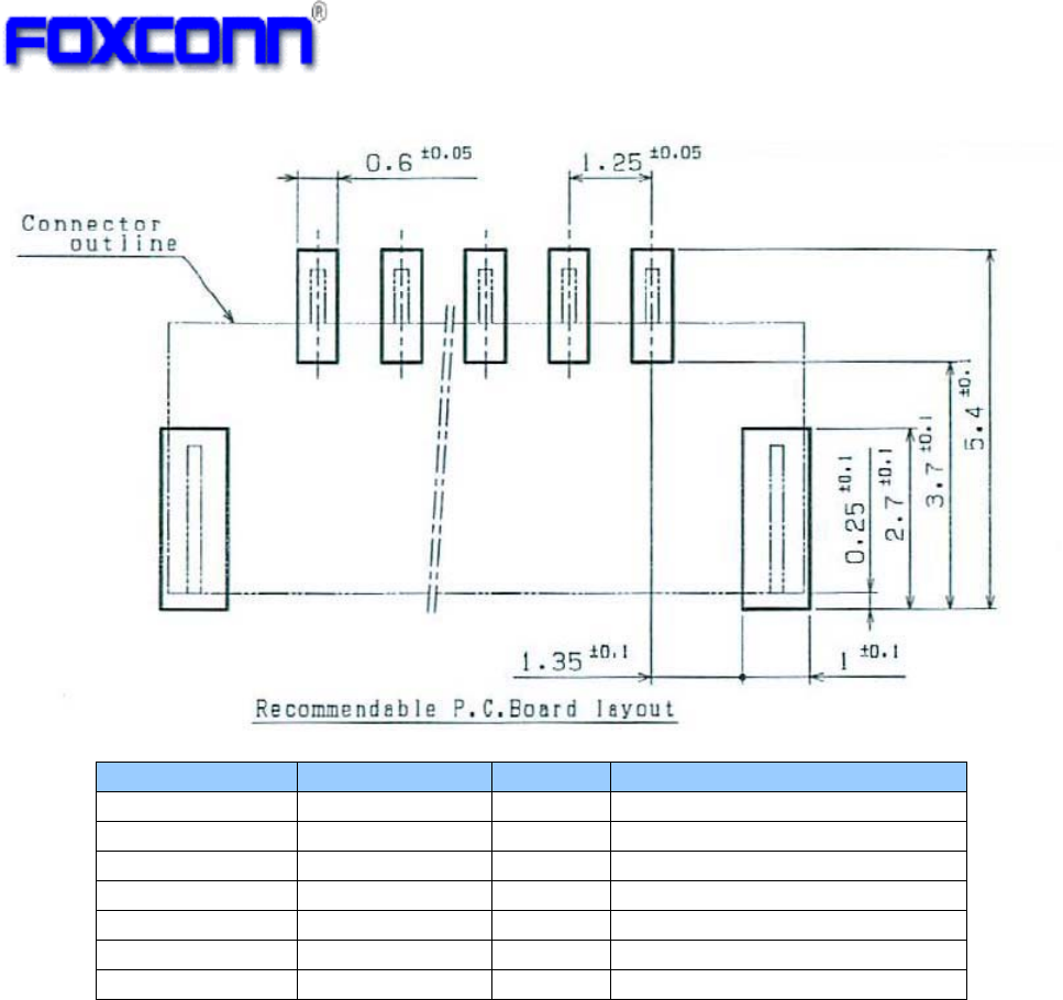
4.3 Interface and Connector
iPin definition:
iVendor: JST
iVendor P/N: SM05B-GHS-TB
!
8!
Pin Number Symbol Name Status Pin definition
1GND Ground
2DP I/O USB positive data
3DM I/O USB negative data
4UV+ P USB +5V power input
5GND Ground
S1 GND Ground
S2 GND Ground
!
9!
5 Electrical Specification
5.1 Absolute maximum rating
!
Element Symbol Min Typ Max Unit
DC supply voltage UV+ 5.0
6.5 (V)
5.2 Recommended operating rating
!
Element Symbol Min Typ Max Unit
DC supply voltage UV+ 4.5 5.0
5.5 (V)
5.3 DC Characteristics
Symbol Parameter Min Typ. Max Unit
UV+
Supply voltage 4.5 5.0 5.5 (V)
2.4GHz Tx Current(1M/15dBm) 200 (mA)
2.4GHz Tx Current(11M/15dBm) - (mA)
2.4GHz Tx Current(6M/15dBm) - (mA)
2.4GHz Tx Current(54M/15dBm) 220 (mA)
2.4GHz Tx
Current(MCS0/15Bm/HT20)
220 (mA)
2.4GHz Tx
Current(MCS7/15dBm/HT20)
220 (mA)
Rx Current 80 (mA)
5GHz Tx Current(6M/12dBm) - (mA)
5GHz Tx Current(54M/12dBm) - (mA)
5GHz Tx
Current(MCS0/12Bm/HT20)
- (mA)
5GHz Tx
Current(MCS7/12dBm/HT20)
- (mA)
5GHz Tx
Current(MCS0/12Bm/HT40)
- (mA)
5GHz Tx
Current(MCS7/12dBm/HT40)
300 (mA)
5GHz Tx
Current(MCS0/11Bm/VHT80)
- (mA)
5GHz Tx
Current(MCS9/11dBm/VHT80)
- (mA)
!
5.4 ESD Information
Mode Level Unit
HBM 1000 V
!
5.5 Environment Storage Condition
!

!
:!
!
!!!!!!!!!!!!!!!!!!!!!!!!!!!!!!!!!!!!
!!!!!!!!!!!!!!!!!!!!!!!!!!!!
!!!!!!!!!!!!!!!!!!!!!!!!!!!!!!!!!!!!!!!!!
!
Environment condition
Temperature Operating Temperature: -10 deg.C ~70 deg.C
Storage Temperature: -40 deg.C ~85 deg.C
Humidity Operating Humidity: 20% ~90%
Storage Humidity: 20% ~90%
!
21!
6 RF Specification
6.1 IEEE802.11b
!!!!!!!!!!!!!!!!!!!!!!!!!!!!!!!!!!!!!!!!!!!!!!!!!!!
Items Contents
Specification IEEE802.11b
Mode DSSS / CCK
Channel CH1 to CH11
Data rate 1, 2, 5.5, 11Mbps
TX Characteristics Min. Typ. Max. Unit
1. Power Levels (Calibrated)
1) Target Power@1Mbps 13.5 15 16.5 dBm
2) Target Power@2Mbps 13.5 15 16.5 dBm
3) Target Power@5.5Mbps 13.5 15 16.5 dBm
4) Target Power@11Mbps 13.5 15 16.5 dBm
2. Spectrum Mask @15dBm
1) fc-33MHz І f І fc-22MHz - - -50 dBr
2) fc-22MHz І f І fc-11MHz - - -30 dBr
3) fc+11MHz І f І fc+22MHz - - -30 dBr
4) fc+22MHz І f І fc+33MHz - - -50 dBr
3. Frequency Error -10 - +10 ppm
4 Modulation Accuracy(EVM)@15dBm
1) 1Mbps - -10 dB
2) 2Mbps - -10 dB
3) 5.5Mbps - -10 dB
4) 11Mbps - -10 dB
RX Characteristics Min. Typ. Max. Unit
5 Minimum Input Level Sensitivity
1) 1Mbps (FERЉ8%) - -92 -91 dBm
2) 2Mbps (FERЉ8%) --91 -89 dBm
3) 5.5Mbps (FERЉ8%) --90 -87 dBm
4) 11Mbps (FERЉ8%) --89 -85 dBm
6 Maximum Input Level (FERЉ8%) -10 -5 - dBm
!
!
!
!
!
!
!
!
!
!
!
!
!
!
!
!
!
!

!
22!
6.2 IEEE802.11g
Items Contents
Specification IEEE802.11g
Mode OFDM
Channel CH1 to CH11
Data rate 6, 9, 12, 18, 24, 36, 48, 54Mbps
TX Characteristics Min. Typ. Max. Unit
1. Power Levels (Calibrated)
1) Target Power@6Mbps 13.5 15 16.5 dBm
2) Target Power@9Mbps 13.5 15 16.5 dBm
3) Target Power@12Mbps 13.5 15 16.5 dBm
4) Target Power@18Mbps 13.5 15 16.5 dBm
5) Target Power@24Mbps 13.5 15 16.5 dBm
6) Target Power@36Mbps 13.5 15 16.5 dBm
7) Target Power@48Mbps 13.5 15 16.5 dBm
8) Target Power@54Mbps 13.5 15 16.5 dBm
2. Spectrum Mask @15dBm
1) at fc +/- 11MHz - - -20 dBr
2) at fc +/- 20MHz - - -28 dBr
3) at fc > +/-30MHz - - -40 dBr
3 Modulation Accuracy(EVM)@15dBm
1) 6Mbps - - -5 dB
2) 9Mbps - - -8 dB
3) 12Mbps - - -10 dB
4) 18Mbps - - -13 dB
5) 24Mbps - - -16 dB
6) 36Mbps - - -19 dB
7) 48Mbps - - -22 dB
8) 54Mbps - -28 -25 dB
4 Frequency Error -10 - +10 ppm
RX Characteristics Min. Typ. Max. Unit
5 Minimum Input Level Sensitivity
1) 6Mbps (PER <10%) - -92 -83 dBm
2) 9Mbps (PER < 10%) - -91 -81 dBm
3) 12Mbps (PER < 10%) - -90 -79 dBm
4) 18Mbps (PER < 10%) - -87 -77 dBm
5) 24Mbps (PER < 10%) - -85 -75 dBm
6) 36Mbps (PER < 10%) - -80 -73 dBm
7) 48Mbps (PER < 10%) - -77 -71 dBm
8) 54Mbps (PER < 10%) - -75 -69 dBm
6 Maximum Input Level (PER < 10%) -20 -11 - dBm
!

!
23!
6.3 802.11n HT20
Items Contents
Specification IEEE802.11n HT20
Mode OFDM
Channel CH2 to CH10
Data rate (MCS index) MCS0/1/2/3/4/5/6/7
TX Characteristics Min. Typ. Max. Unit
1. Power Levels (Calibrated)
1) Target Power@MCS0 13.5 15 16.5 dBm
2) Target Power@ MCS1 13.5 15 16.5 dBm
3) Target Power@ MCS2 13.5 15 16.5 dBm
4) Target Power@ MCS3 13.5 15 16.5 dBm
5) Target Power@ MCS4 13.5 15 16.5 dBm
6) Target Power@ MCS5 13.5 15 16.5 dBm
7) Target Power@ MCS6 13.5 15 16.5 dBm
8) Target Power@ MCS7 13.5 15 16.5 dBm
2. Spectrum Mask @15dBm
1) at fc +/- 11MHz - - -20 dBr
2) at fc +/- 20MHz - - -28 dBr
3) at fc > +/-30MHz - - -45 dBr
3. Modulation Accuracy(EVM)@15dBm
1) MCS0 - - -5 dB
2) MCS1 - - -10 dB
3) MCS2 - - -13 dB
4) MCS3 - - -16 dB
5) MCS4 - - -19 dB
6) MCS5 - - -22 dB
7) MCS6 - - -25 dB
8) MCS7 - - -28 dB
4. Frequency Error -10 - +10 ppm
RX Characteristics Min. Typ. Max. Unit
5. Minimum Input Level Sensitivity
1) MCS0 (PER < 10%) - -91 -81 dBm
2) MCS1 (PER < 10%) - -89 -79 dBm
3) MCS2 (PER < 10%) - -87 -77 dBm
4) MCS3 (PER < 10%) - -84 -75 dBm
5) MCS4 (PER < 10%) - -80 -73 dBm
6) MCS5 (PER < 10%) - -75 -71 dBm
7) MCS6 (PER < 10%) - -74 -69 dBm
8) MCS7 (PER < 10%) - -72 -67 dBm
6. Maximum Input Level (PER < 10%) -20 -10 - dBm

!
24!
Items Contents
Specification IEEE802.11n HT20
Mode OFDM
Channel CH1, CH11
Data rate (MCS index) MCS0/1/2/3/4/5/6/7
TX Characteristics Min. Typ. Max. Unit
1. Power Levels (Calibrated)
1) Target Power@MCS0 12.5 14 15.5 dBm
2) Target Power@ MCS1 12.5 14 15.5 dBm
3) Target Power@ MCS2 12.5 14 15.5 dBm
4) Target Power@ MCS3 12.5 14 15.5 dBm
5) Target Power@ MCS4 12.5 14 15.5 dBm
6) Target Power@ MCS5 12.5 14 15.5 dBm
7) Target Power@ MCS6 12.5 14 15.5 dBm
8) Target Power@ MCS7 12.5 14 15.5 dBm
2. Spectrum Mask @15dBm
1) at fc +/- 11MHz - - -20 dBr
2) at fc +/- 20MHz - - -28 dBr
3) at fc > +/-30MHz - - -45 dBr
3. Modulation Accuracy(EVM)@15dBm
1) MCS0 - - -5 dB
2) MCS1 - - -10 dB
3) MCS2 - - -13 dB
4) MCS3 - - -16 dB
5) MCS4 - - -19 dB
6) MCS5 - - -22 dB
7) MCS6 - - -25 dB
8) MCS7 - - -28 dB
4. Frequency Error -10 - +10 ppm
RX Characteristics Min. Typ. Max. Unit
5. Minimum Input Level Sensitivity
1) MCS0 (PER < 10%) - -91 -81 dBm
2) MCS1 (PER < 10%) - -89 -79 dBm
3) MCS2 (PER < 10%) - -87 -77 dBm
4) MCS3 (PER < 10%) - -84 -75 dBm
5) MCS4 (PER < 10%) - -80 -73 dBm
6) MCS5 (PER < 10%) - -75 -71 dBm
7) MCS6 (PER < 10%) - -74 -69 dBm
8) MCS7 (PER < 10%) - -72 -67 dBm
6. Maximum Input Level (PER < 10%) -20 -10 - dBm

!
25!
6.4 802.11a
Items Contents
Specification IEEE802.11a
Mode OFDM
Channel CH36 to CH165
Data rate 6, 9, 12, 18, 24, 36, 48, 54Mbps
TX Characteristics Min. Typ. Max. Unit
1. Power Levels (Calibrated)
1) Target Power@6Mbps 10.5 12 13.5 dBm
2) Target Power@9Mbps 10.5 12 13.5 dBm
3) Target Power@12Mbps 10.5 12 13.5 dBm
4) Target Power@18Mbps 10.5 12 13.5 dBm
5) Target Power@24Mbps 10.5 12 13.5 dBm
6) Target Power@36Mbps 10.5 12 13.5 dBm
7) Target Power@48Mbps 10.5 12 13.5 dBm
8) Target Power@54Mbps 10.5 12 13.5 dBm
2. Spectrum Mask @12dBm
1) at fc +/- 11MHz - - -20 dBr
2) at fc +/- 20MHz - - -28 dBr
3) at fc > +/-30MHz - - -40 dBr
3 Modulation Accuracy(EVM)@15dBm
1) 6Mbps - - -5 dB
2) 9Mbps - - -8 dB
3) 12Mbps - - -10 dB
4) 18Mbps - - -13 dB
5) 24Mbps - - -16 dB
6) 36Mbps - - -19 dB
7) 48Mbps - - -22 dB
8) 54Mbps - -28 -25 dB
4 Frequency Error -10 - +10 ppm
RX Characteristics Min. Typ. Max. Unit
5 Minimum Input Level Sensitivity
1) 6Mbps (PER <10%) - -92 -83 dBm
2) 9Mbps (PER < 10%) - -91 -81 dBm
3) 12Mbps (PER < 10%) - -90 -79 dBm
4) 18Mbps (PER < 10%) - -87 -77 dBm
5) 24Mbps (PER < 10%) - -85 -75 dBm
6) 36Mbps (PER < 10%) - -80 -73 dBm
7) 48Mbps (PER < 10%) - -77 -71 dBm
8) 54Mbps (PER < 10%) - -75 -69 dBm
6 Maximum Input Level (PER < 10%) -20 -11 - dBm
!
!
!
!
!
!
!
!
!
!
!
!

!
26!
6.5 802.11an HT20
!
!
!
!
!
!
!
!
!
Items Contents
Specification IEEE802.11an HT20
Mode OFDM
Channel CH36 to CH165
Data rate (MCS index) MCS0/1/2/3/4/5/6/7
TX Characteristics Min. Typ. Max. Unit
1. Power Levels (Calibrated)
1) Target Power@MCS0 10.5 12 13.5 dBm
2) Target Power@ MCS1 10.5 12 13.5 dBm
3) Target Power@ MCS2 10.5 12 13.5 dBm
4) Target Power@ MCS3 10.5 12 13.5 dBm
5) Target Power@ MCS4 10.5 12 13.5 dBm
6) Target Power@ MCS5 10.5 12 13.5 dBm
7) Target Power@ MCS6 10.5 12 13.5 dBm
8) Target Power@ MCS7 10.5 12 13.5 dBm
2. Spectrum Mask @15dBm
1) at fc +/- 11MHz - - -20 dBr
2) at fc +/- 20MHz - - -28 dBr
3) at fc > +/-30MHz - - -45 dBr
3. Modulation Accuracy(EVM)@15dBm
1) MCS0 - - -5 dB
2) MCS1 - - -10 dB
3) MCS2 - - -13 dB
4) MCS3 - - -16 dB
5) MCS4 - - -19 dB
6) MCS5 - - -22 dB
7) MCS6 - - -25 dB
8) MCS7 - - -28 dB
4. Frequency Error -10 - +10 ppm
RX Characteristics Min. Typ. Max. Unit
5. Minimum Input Level Sensitivity
1) MCS0 (PER < 10%) - -91 -81 dBm
2) MCS1 (PER < 10%) - -89 -79 dBm
3) MCS2 (PER < 10%) - -87 -77 dBm
4) MCS3 (PER < 10%) - -84 -75 dBm
5) MCS4 (PER < 10%) - -80 -73 dBm
6) MCS5 (PER < 10%) - -75 -71 dBm
7) MCS6 (PER < 10%) - -74 -69 dBm
8) MCS7 (PER < 10%) - -72 -67 dBm
6. Maximum Input Level (PER < 10%) -20 -10 - dBm

!
27!
6.6 802.11an HT40
!
Items Contents
Specification IEEE802.11an HT20
Mode OFDM
Channel CH38 to CH159
Data rate (MCS index) MCS0/1/2/3/4/5/6/7
TX Characteristics Min. Typ. Max. Unit
1. Power Levels (Calibrated)
1) Target Power@MCS0 10.5 12 13.5 dBm
2) Target Power@ MCS1 10.5 12 13.5 dBm
3) Target Power@ MCS2 10.5 12 13.5 dBm
4) Target Power@ MCS3 10.5 12 13.5 dBm
5) Target Power@ MCS4 10.5 12 13.5 dBm
6) Target Power@ MCS5 10.5 12 13.5 dBm
7) Target Power@ MCS6 10.5 12 13.5 dBm
8) Target Power@ MCS7 10.5 12 13.5 dBm
2. Spectrum Mask @15dBm
1) at fc +/- 11MHz - - -20 dBr
2) at fc +/- 20MHz - - -28 dBr
3) at fc > +/-30MHz - - -45 dBr
3. Modulation Accuracy(EVM)@15dBm
1) MCS0 - - -5 dB
2) MCS1 - - -10 dB
3) MCS2 - - -13 dB
4) MCS3 - - -16 dB
5) MCS4 - - -19 dB
6) MCS5 - - -22 dB
7) MCS6 - - -25 dB
8) MCS7 - - -28 dB
4. Frequency Error -10 - +10 ppm
RX Characteristics Min. Typ. Max. Unit
5. Minimum Input Level Sensitivity
1) MCS0 (PER < 10%) - -88 -78 dBm
2) MCS1 (PER < 10%) - -86 -76 dBm
3) MCS2 (PER < 10%) - -84 -74 dBm
4) MCS3 (PER < 10%) - -81 -72 dBm
5) MCS4 (PER < 10%) - -77 -70 dBm
6) MCS5 (PER < 10%) - -72 -68 dBm
7) MCS6 (PER < 10%) - -71 -66 dBm
8) MCS7 (PER < 10%) - -69 -64 dBm
6. Maximum Input Level (PER < 10%) -20 -10 - dBm

!
28!
6.7 802.11ac HT80
!
!
!
!
!
!
!
!
Items Contents
Specification IEEE802.11ac HT80
Mode OFDM
Channel CH42 to CH155
Data rate (MCS index) MCS0/1/2/3/4/5/6/7/8/9
TX Characteristics Min. Typ. Max. Unit
1. Power Levels (Calibrated)
1) Target Power@MCS0 9.5 11 12.5 dBm
2) Target Power@ MCS1 9.5 11 12.5 dBm
3) Target Power@ MCS2 9.5 11 12.5 dBm
4) Target Power@ MCS3 9.5 11 12.5 dBm
5) Target Power@ MCS4 9.5 11 12.5 dBm
6) Target Power@ MCS5 9.5 11 12.5 dBm
7) Target Power@ MCS6 9.5 11 12.5 dBm
8) Target Power@ MCS7 9.5 11 12.5 dBm
2. Spectrum Mask @15dBm
1) at fc +/- 11MHz - - -20 dBr
2) at fc +/- 20MHz - - -28 dBr
3) at fc > +/-30MHz - - -45 dBr
3. Modulation Accuracy(EVM)@15dBm
1) MCS0 - - -5 dB
2) MCS1 - - -10 dB
3) MCS2 - - -13 dB
4) MCS3 - - -16 dB
5) MCS4 - - -19 dB
6) MCS5 - - -22 dB
7) MCS6 - - -25 dB
8) MCS7 - - -28 dB
4. Frequency Error -10 - +10 ppm
RX Characteristics Min. Typ. Max. Unit
5. Minimum Input Level Sensitivity
1) MCS0 (PER < 10%) - -80 -75 dBm
2) MCS1 (PER < 10%) - -78 -73 dBm
3) MCS2 (PER < 10%) - -76 -71 dBm
4) MCS3 (PER < 10%) - -74 -69 dBm
5) MCS4 (PER < 10%) - -72 -67 dBm
6) MCS5 (PER < 10%) - -70 -65 dBm
7) MCS6 (PER < 10%) - -68 -63 dBm
8) MCS7 (PER < 10%) - -66 -61 dBm
9) MCS7 (PER < 10%) - -63 -58 dBm
10) MCS7 (PER < 10%) - -59 -54 dBm
6. Maximum Input Level (PER < 10%) -20 -10 - dBm

!
29!
6.8 Bluetooth 3.0
!
!
!
Items Contents
- TX Characteristics - Min. Typ. Max. Unit
1. Power Levels !
BT Output Power (Basic Data Rate) -3 0 2 dBm
2. Initial Carrier Frequenc
y
Tolerance
Average Offset -75 0 75 kHz
3. Carrier Drift
Drift Rate
DH1 -20 0 20 kHz/50us
DH3 -20 0 20 kHz/50us
DH5 -20 0 20 kHz/50us
Average Drift
DH1 -25 0 25 kHz
DH3 -40 0 40
kHz
DH5 -40 0 40
kHz
4. Modulation Characteristic
F1avg 140 150 175 kHz
F2max 115 140 kHz
F1/F2 Ratio 0.8 0.96
5. EDR Carrier Frequency Stability and Modulation Accuracy
2Mbps:
±
/4 DQPSK
Initial Frequency Error: j-75 0 75 kHz
Frequency Error: 1-10 0 10
kHz
Block Frequency Error: j!,!1-75 0 75 kHz
RMS DEVM - 0.05 0.2
Peak DEVM - 0.12 0.35
99% DEVM (% Symbols <=0.3) 99% 100%
3Mbps:
8DPSK
Initial Frequency Error: j-75 0 75 kHz
Frequency Error: 1-10 0 10 kHz
Block Frequency Error: j!,!1-75 0 75
kHz
RMS DEVM - 0.05 0.13
Peak DEVM - 0.13 0.25
99% DEVM (% Symbols <=0.13) 99% 100%
- RX Characteristics - Min. Typ. Max. Unit
1. Minimum Input Level Sensitivit
y
!!! !
GFSK (1Mbps) - -88 -79 dBm
±/4 DQPSK (2Mbps) - -88 -79 dBm
8DPSK (3Mbps) - -84 -76 dBm

!
2:!
6.9 Antenna Electrical Specification
!
Parameter Value Units
Operating frequency range 2.4 ~ 2.4835
5.15~5.85
GHz
Antenna gain (max) -0.4
1.12
dBi (Main Antenna)
Antenna gain (max) 0.28
0.9
dBi (Aux Antenna)
!
31!
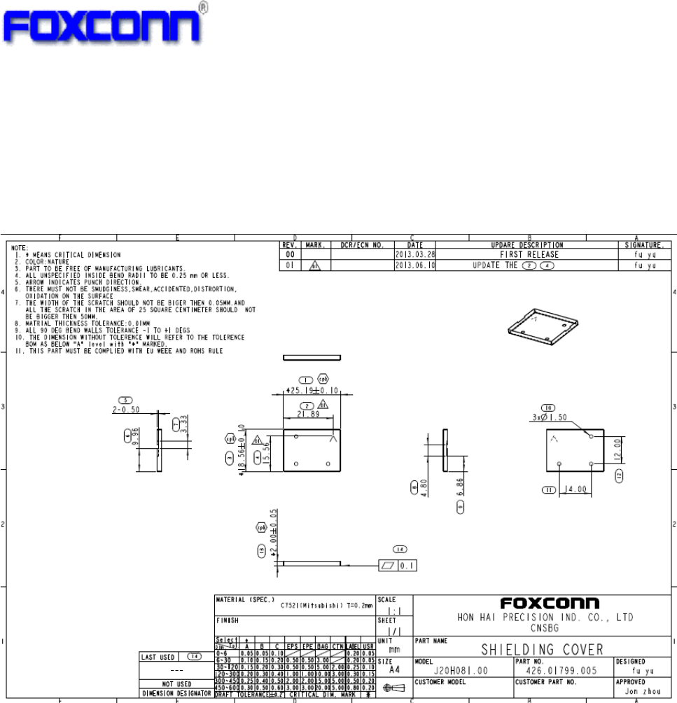
7 Mechanical Specifications
7.1 Shielding Cover Dimension
Dimension (LxWxH): 25.19mm x 18.56mm x 2.0mm
Thickness: 0.2mm
!
!
!
!
!
!
!
!
!
32!
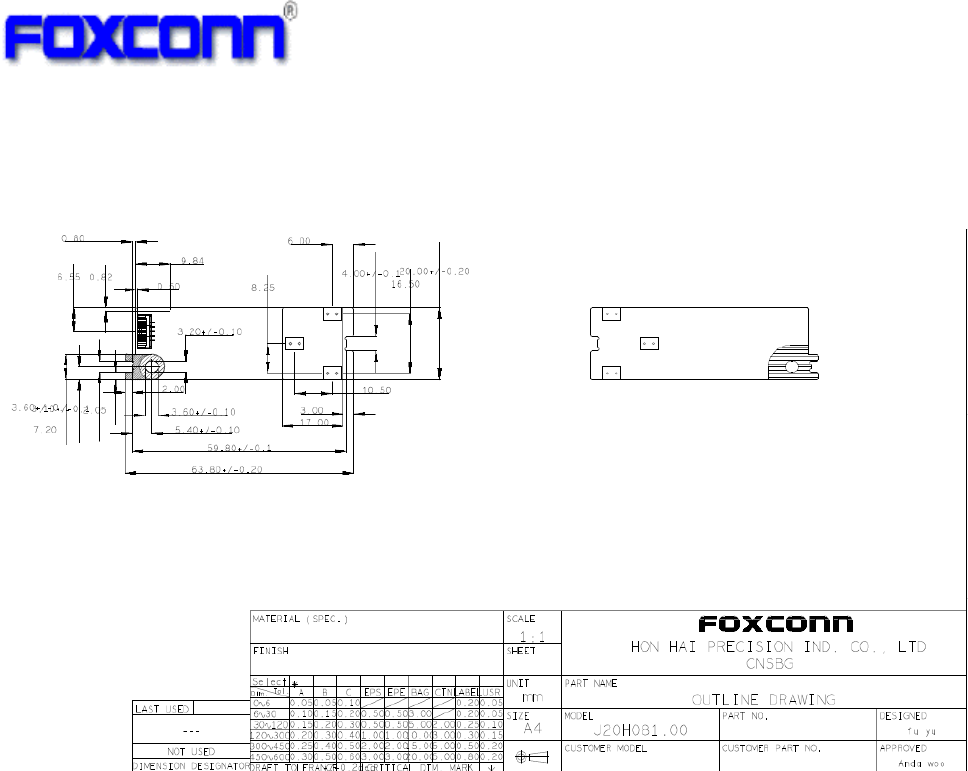
7.2 PCB Assembly Dimension
Dimension (W x Lx H ): 63.8mmx20mmx1.0mm
PCB: 4 layer HF-FR4 design
Industry Canada statement:
This device complies with RSS-210 of the Industry Canada Rules. Operation is subject to
the following two conditions: (1) This device may not cause harmful interference, and (2)
this device must accept any interference received, including interference that may cause
undesired operation.
Ce dispositif est conforme à la norme CNR-210 d'Industrie Canada applicable aux
appareils radio exempts de licence. Son fonctionnement est sujet aux deux conditions
suivantes: (1) le dispositif ne doit pas produire de brouillage préjudiciable, et (2) ce
dispositif doit accepter tout brouillage reçu, y compris un brouillage susceptible de
provoquer un fonctionnement indésirable.
Radiation Exposure Statement:
This equipment complies with IC radiation exposure limits set forth for an uncontrolled
environment. This equipment should be installed and operated with minimum distance
20cm between the radiator & your body.
Déclaration d'exposition aux radiations:
Cet équipement est conforme aux limites d'exposition aux rayonnements IC établies pour
un environnement non contrôlé. Cet équipement doit être installé et utilisé avec un
minimum de 20 cm de distance entre la source de rayonnement et votre corps.
This device is intended only for OEM integrators under the following conditions:
(For module device use)
1) The antenna must be installed such that 20 cm is maintained between the antenna and
users, and
2) The transmitter module may not be co-located with any other transmitter or antenna.
As long as 2 conditions above are met, further transmitter test will not be required.

!
33!
However, the OEM integrator is still responsible for testing their end-product for any
additional compliance requirements required with this module installed.
Cet appareil est conçu uniquement pour les intégrateurs OEM dans les conditions
suivantes: (Pour utilisation de dispositif module)
1) L'antenne doit être installée de telle sorte qu'une distance de 20 cm est respectée entre
l'antenne et les utilisateurs, et
2) Le module émetteur peut ne pas être coïmplanté avec un autre émetteur ou antenne.
Tant que les 2 conditions ci-dessus sont remplies, des essais supplémentaires sur
l'émetteur ne seront pas nécessaires. Toutefois, l'intégrateur OEM est toujours
responsable des essais sur son produit final pour toutes exigences de conformité
supplémentaires requis pour ce module installé.
IMPORTANT NOTE:
In the event that these conditions can not be met (for example certain laptop configurations
or co-location with another transmitter), then the Canada authorization is no longer
considered valid and the IC ID can not be used on the final product. In these
circumstances, the OEM integrator will be responsible for re-evaluating the end product
(including the transmitter) and obtaining a separate Canada authorization.
NOTE IMPORTANTE:
Dans le cas où ces conditions ne peuvent être satisfaites (par exemple pour certaines
configurations d'ordinateur portable ou de certaines co-localisation avec un autre
émetteur), l'autorisation du Canada n'est plus considéré comme valide et l'ID IC ne peut
pas être utilisé sur le produit final. Dans ces circonstances, l'intégrateur OEM sera chargé
de réévaluer le produit final (y compris l'émetteur) et l'obtention d'une autorisation distincte
au Canada.
End Product Labeling
This transmitter module is authorized only for use in device where the antenna may be
installed such that 20 cm may be maintained between the antenna and users. The final
end product must be labeled in a visible area with the following: “Contains IC:
2878D-J20H081”.
Plaque signalétique du produit final
Ce module émetteur est autorisé uniquement pour une utilisation dans un dispositif où
l'antenne peut être installée de telle sorte qu'une distance de 20cm peut être maintenue
entre l'antenne et les utilisateurs. Le produit final doit être étiqueté dans un endroit visible
avec l'inscription suivante: "Contient des IC: 2878D- J20H081".
Manual Information To the End User
The OEM integrator has to be aware not to provide information to the end user regarding
how to install or remove this RF module in the user’s manual of the end product which
integrates this module.
The end user manual shall include all required regulatory information/warning as show in
this manual.
Manuel d'information à l'utilisateur final
L'intégrateur OEM doit être conscient de ne pas fournir des informations à l'utilisateur final
quant à la façon d'installer ou de supprimer ce module RF dans le manuel de l'utilisateur
du produit final qui intègre ce module.
Le manuel de l'utilisateur final doit inclure toutes les informations réglementaires requises
et avertissements comme indiqué dans ce manuel.
Caution :
(i) the device for operation in the band 5150-5250 MHz is only for indoor use to reduce the
potential for harmful interference to co-channel mobile satellite systems;
(ii) the maximum antenna gain permitted for devices in the bands 5250-5350 MHz and

!
34!
5470-5725 MHz shall comply with the e.i.r.p. limit; and
(iii) the maximum antenna gain permitted for devices in the band 5725-5825 MHz shall
comply with the e.i.r.p. limits specified for point-to-point and non point-to-point operation as
appropriate.
(iv) Users should also be advised that high-power radars are allocated as primary users
(i.e. priority users) of the bands 5250-5350 MHz and 5650-5850 MHz and that these radars
could cause interference and/or damage to LE-LAN devices.
Avertissement:
Le guide d’utilisation des dispositifs pour réseaux locaux doit inclure des instructions
précises sur les restrictions susmentionnées, notamment :
(i) les dispositifs fonctionnant dans la bande 5 150-5 250 MHz sont réservés uniquement
pour une utilisation à l’intérieur afin de réduire les risques de brouillage préjudiciable aux
systèmes de satellites mobiles utilisant les mêmes canaux;
(ii) le gain maximal d’antenne permis pour les dispositifs utilisant les bandes 5 250-5 350
MHz et 5 470-5 725 MHz doit se conformer à la limite de p.i.r.e.;
(iii) le gain maximal d’antenne permis (pour les dispositifs utilisant la bande 5 725-5 825
MHz) doit se conformer à la limite de p.i.r.e. spécifiée pour l’exploitation point à point et
non point à point, selon le cas.
(iv) De plus, les utilisateurs devraient aussi être avisés que les utilisateurs de radars de
haute puissance sont désignés utilisateurs principaux (c.-à-d., qu’ils ont la priorité) pour les
bandes 5 250-5 350 MHz et 5 650-5 850 MHz et que ces radars pourraient causer du
brouillage et/ou des dommages aux dispositifs LAN-EL.
Federal Communication Commission Interference Statement
This device complies with Part 15 of the FCC Rules. Operation is subject to the
following two conditions: (1) This device may not cause harmful interference, and
(2) this device must accept any interference received, including interference that
may cause undesired operation.
This equipment has been tested and found to comply with the limits for a Class B
digital device, pursuant to Part 15 of the FCC Rules. These limits are designed to
provide reasonable protection against harmful interference in a residential
installation. This equipment generates, uses and can radiate radio frequency energy
and, if not installed and used in accordance with the instructions, may cause
harmful interference to radio communications. However, there is no guarantee that
interference will not occur in a particular installation. If this equipment does cause
harmful interference to radio or television reception, which can be determined by
turning the equipment off and on, the user is encouraged to try to correct the
interference by one of the following measures:
- Reorient or relocate the receiving antenna.
- Increase the separation between the equipment and receiver.
- Connect the equipment into an outlet on a circuit different from that
to which the receiver is connected.
- Consult the dealer or an experienced radio/TV technician for help.
FCC Caution: Any changes or modifications not expressly approved by the party

!
35!
responsible for compliance could void the user's authority to operate this equipment.
This transmitter must not be co-located or operating in conjunction with any other
antenna or transmitter.
!
Operations in the 5.15-5.25GHz band are restricted to indoor usage only.
Radiation Exposure Statement:
This equipment complies with FCC radiation exposure limits set forth for an
uncontrolled environment. This equipment should be installed and operated with
minimum distance 20cm between the radiator & your body.
This device is intended only for OEM integrators under the following conditions:
1) The antenna must be installed such that 20 cm is maintained between the antenna
and users, and 2) The transmitter module may not be co-located with any other transmitter
or antenna.
As long as 2 conditions above are met, further transmitter test will not be required.
However, the OEM integrator is still responsible for testing their end-product for any
additional compliance requirements required with this module installed
IMPORTANT NOTE: In the event that these conditions can not be met (for example
certain laptop configurations or co-location with another transmitter), then the FCC
authorization is no longer considered valid and the FCC ID can not be used on the
final product. In these circumstances, the OEM integrator will be responsible for
reevaluating
the end product (including the transmitter) and obtaining a separate FCC
authorization.
End Product Labeling
This transmitter module is authorized only for use in device where the antenna may be
installed such that 20 cm may be maintained between the antenna and users. The
final end product must be labeled in a visible area with the following: “Contains FCC
ID: MCLJ20H081”. The grantee's FCC ID can be used only when all FCC compliance
requirements are met.
Manual Information To the End User
The OEM integrator has to be aware not to provide information to the end user
regarding how to install or remove this RF module in the user’s manual of the end
product which integrates this module.
The end user manual shall include all required regulatory information/warning as show
in this manual.
For Taiwan ᤞΚ!(ሽॾጥࠫ୴᙮ᕴޗࠌش)
ᆖীڤᎁᢞٽհ܅פ୴᙮ሽᖲΔॺᆖױΔֆΕᇆࢨࠌشृ݁լᖐ۞᧢ޓ᙮!
ΕףՕפࢨ᧢ޓૠհࢤ֗פ౨Ζ!
܅פ୴᙮ሽᖲհࠌشլᐙଆڜ٤֗եឫٽऄຏॾΙᆖ࿇ڶեឫွழΔᚨم!
ܛೖشΔࠀޏ۟ྤեឫழֱᤉᥛࠌشΖছႈٽऄຏॾΔਐࠉሽॾऄࡳ܂ᄐհྤᒵ!
ሽຏॾΖ܅פ୴᙮ሽᖲႊݴ࠹ٽऄຏॾࢨՠᄐΕઝᖂ֗᠔᛭شሽंᘿ୴ࢤሽᖲໂհ!
եឫΖ!
Note: 1. ءᑓิ࣍࠷ᎁᢞ৵ലࠉࡳ࣍ᑓิء᧯ᑑقᐉ᧭ٽᑑ᧘!2. ߓอᐗᚨ࣍ؓ!
Ղᑑقψءขփܶ୴᙮ᑓิ: XXXyyyLPDzzzz-x (NCC ID) ωڗᑌ!
!
!

!
36!
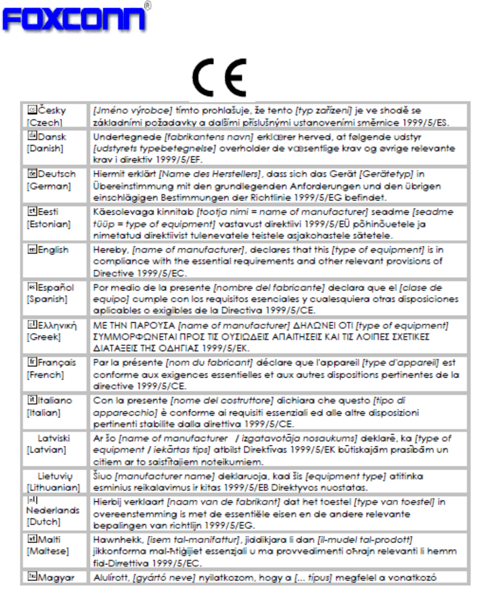
Europe – EU Declaration of Conformity
This device complies with the essential requirements of the R&TTE Directive 1999/5/EC. The following test methods
have been
applied in order to prove presumption of conformity with the essential requirements of the R&TTE Directive 1999/5/EC:
EN 60950Ͳ1: 2006+A11:2009+A1:2010+A12:2011
Safety of Information Technology Equipment
EN 62311: 2008
Assessment of electronic and electrical equipment related to human exposure restrictions for electromagnetic fields (0
HzͲ300 GHz)
(IEC 62311:2007 (Modified))
EN 300 328 V1.8.1 (2012);
Electromagnetic compatibility and Radio spectrum Matters (ERM); Wideband Transmission systems; Data transmission
equipment operating in the 2,4 GHz ISM band and using spread spectrum modulation techniques; Harmonized EN
covering
essential requirements under article 3.2 of the R&TTE Directive
EN 301 893 V1.7.1: (2012)
Broadband Radio Access Networks (BRAN); 5 GHz high performance RLAN; Harmonized EN covering essential
requirements of article 3.2 of the R&TTE Directive
EN 301 489-1 V1.9.2 (2011)
Electromagnetic compatibility and Radio Spectrum Matters (ERM); ElectroMagnetic Compatibility (EMC) standard for
radio equipment and services; Part 1: Common technical requirements
EN 301 489-17 V2.2.1 (2012)
Electromagnetic compatibility and Radio spectrum Matters (ERM); ElectroMagnetic Compatibility (EMC) standard for
radio equipment and services; Part 17: Specific conditions for 2,4 GHz wideband transmission systems and 5 GHz high
performance RLAN equipment National Authorities were informed according to Article 6.4 of Frequency Notification.
Special Requirements are considered. The product is labeled with CE Marking.
!
37!