HON HAI PRECISION IND J20H085 802.11abgn/BT3.0 Wireless Module User Manual User s manual 1110
HON HAI Precision Ind. Co., Ltd. 802.11abgn/BT3.0 Wireless Module User s manual 1110
User Manual.pdf
1
Project Name MT7650 IEEE802.11a/b/g/n 1×1 +
Bluetooth3.0, WiFi+BT module
Approval Sheet Rev. 1.0
Foxconn Part No. J20H085.00
J20H085.01
Sony Part No. 1-458-765-31 (J20H085.00)
1-458-765-21 (J20H085.01)
Prepared by Reviewed by Approved by
Clon Liu Eddie Huang
Ambit
Microsystems
(Shanghai
)
LTD.
No 1925, Nanle Road Songjiang Export
Processing Zone Shanghai, China
Tel :86-21-61206688 Ext:22165
FAX:86-21-57749230
J20H085
User Manual

2
CONTENTS
1
REVISION HISTORY
................................
................................................................
................................................................
................................................................
....................................
........
....
4
44
4
2
MANUFACTURING INFORMATION
................................
................................................................
.......................................................
..............................................
.......................
5
55
5
3
PRODUCT OVERVIEW
................................
................................................................
................................................................
................................................................
..................................
....
..
6
66
6
3.1
A
PPLICATION SCOPE
.................................................................... 6
3.2
R
EGULATION OF EACH COUNTRIES
......................................................... 7
4
MODULE HARDWARE OVERVIEW
................................
................................................................
.......................................................
..............................................
.......................
8
88
8
4.1
B
LOCK
D
IAGRAM
....................................................................... 8
4.2
F
EATURES
............................................................................ 8
4.3
I
NTERFACE AND
C
ONNECTOR
............................................................. 8
5
GENERAL SPECIFICATION
................................
................................................................
.............................................................
..........................................................
.............................
10
1010
10
6
ELECTRICAL SPECIFICATION
................................
................................................................
..........................................................
....................................................
..........................
11
1111
11
6.1
A
BSOLUTE MAXIMUM RATING
............................................................ 11
6.2
R
ECOMMENDED OPERATING RATING
...................................................... 11
6.3
DC
C
HARACTERISTICS
................................................................. 11
6.4
ESD
I
NFORMATION
.................................................................... 11
6.5
E
NVIRONMENT
S
TORAGE
C
ONDITION
...................................................... 11
7
RF SPECIFICATION
................................
................................................................
................................................................
................................................................
....................................
........
....
12
1212
12
7.1
IEEE802.11
B
........................................................................ 12
7.2
IEEE802.11
G
........................................................................ 13
7.3
IEEE
802.11
N
HT20 .................................................................. 14
7.4
IEEE
802.11
A
........................................................................ 15
7.5
IEEE
802.11
AN
HT20 ................................................................. 16
7.6
IEEE
802.11
AN
HT40 ................................................................. 17
7.7
B
LUETOOTH
3.0 ....................................................................... 18
7.8
A
NTENNA
E
LECTRICAL
S
PECIFICATION
(J20H085.01)......................................... 19
7.9
P
OWER UP SEQUENCE
...................................................................
8
MECHANICAL SPECIFICATIONS
................................
................................................................
..........................................................
....................................................
..........................
8.1
S
HIELDING
C
OVER
D
IMENSION
.............................................................
8.2
PCB
A
SSEMBLY
D
IMENSION
...............................................................
8.3
M
OUNT
P
OSITION OF
M
ATERIALS
...........................................................
9
SCHEMATICS
................................
................................................................
................................................................
................................................................
...........................................
......................
...........
10
LAYOUT PATTERN
................................
................................................................
................................................................
................................................................
......................................
............
......
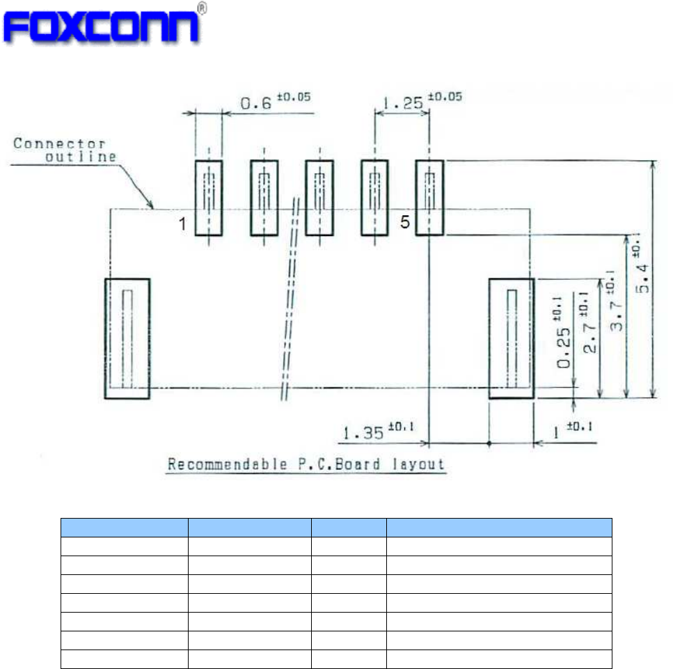
10.1
M
AIN
PCB
LAYOUT
(T
OP VIEW
) ............................................................
10.2
A
NTENNA
PCB
LAYOUT
...................................................................
10.3
PCB
S
PECIFICATION
.....................................................................
11
BOM (BILL OF MATERIALS)
................................
................................................................
..............................................................
............................................................
..............................
12
OTP CONTENT
................................
................................................................
................................................................
................................................................
..........................................
....................
..........
13
LABEL INFORMATION
................................
................................................................
................................................................
................................................................
...................................
......
...
13.1
MAC
ID
L
ABEL
(
FOR
PVT,
MP) ............................................................
14
PACKAGE AND STACK INFORMATION
................................
................................................................
....................................................
........................................
....................
14.1
C
ARTON
ASSY .........................................................................
14.2
P
ALLET
ASSY ..........................................................................

3
14.3
T
RAY
ID
L
ABEL
.........................................................................
14.4
C
ARTON
L
ABEL
.........................................................................
14.5
P
ALLET
L
ABEL
..........................................................................
15
RELIABILITY TEST PLAN
................................
................................................................
................................................................
................................................................
.................................
..
.
16
HANDLING NOTICE
................................
................................................................
................................................................
................................................................
....................................
........
....
20
2020
20
18
NOTIFICATION
................................
................................................................
................................................................
................................................................
........................................
................
........
21
2121
21

4
1 Revision History
Date Revision Change Description
2014/10/18
1.0 Initial release

5
2 Manufacturing Information
Manufacture Country:
Made in China
Manufacturer:
Ambit Microsystems (Shanghai) LTD.
Manufacture Address:
No 1925, Nanle Road Songjiang Export Processing Zone Shanghai, China

6
3 Product Overview
The J20H085 802.11a/b/g/n and BT3.0 module provides wireless modem functionality
utilizing direct sequence spread spectrum and OFDM/CCK technology. This module is
based on MTK MT7650U solution .It fully complies with IEEE 802.11n,IEEE 802.11 a/b/g
and ,Bluetooth v2.1+EDR, v3.0 standard, offering feature-rich wireless connectivity at high
standards, and delivering reliable, cost-effective throughput from an extended distance.
Optimized RF architecture and baseband algorithms provide superb performance and low
power consumption. Intelligent MAC design deploys a high efficient DMA engine and
hardware data processing accelerators which offloads the host processor.
3.1 Application scope
The wireless LAN is compliant to IEEE 802.11n,IEEE 802.11 a/b/g standards. The data
rate of 802.11b is up to 11Mbps and fallback rates of 5.5, 2, 1Mbps. The data rate of
802.11a/g is up to 54Mbps and fallback rates of 48,36,24,18,12,9, 6Mbps. The data rate of
802.11n HT20 is up to 65Mbps and fallback rates of 58.5, 52, 39, 26, 19.5, 13, 6.5Mbps;
The data rate of 802.11n HT40 is up to 130Mbps and fallback rates of 117, 104, 78, 52, 39,
26, 13Mbps;
The BT Module is compliant to Bluetooth 3.0 and EDR standard:
Carrier Frequency: 2402MHz ~ 2480 MHz
Carrier Spacing: 1.0MHz
Duplexing: TDD
Modulation: FHSS
GFSK, pi/4-DQPSK, 8DPSK
Symbol Rate: 1Mbps (GFSK), 2Mbps (pi/4-DQPSK), 3Mbps (8DPSK)

7
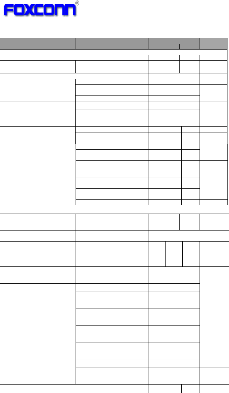
3.2 Regulation of each countries
Country Approval Certification Certification No. Description
United States Module FCC Part 15C/E
Canada Module RSS-210 issue8
Europe Plug-in
EN 300 328 v1.8.1
EN 301 893 v1.7.1
EN 301 489
EN 60950
EN 62311
Russia Module FAC
Japan Module TECEC
Taiwan Module NCC
Malaysia Module SIRIM
South Africa Module ICASA
UAE Module TRA

8
4 Module Hardware Overview
4.1 Block Diagram
The general HW architecture is shown below Figure:
.
4.2 Features
♦ IEEE802.11a/b/g/n (1X1) based on MTK MT7650U solution.
♦ Support BT3.0
♦ USB 2.0 Interface, High and Full Speeds supported.
♦ Module is powered by the host with a 5.0V +/- 10% supply.
♦ External PCB printed antennas.
♦ 4 layers through hole PCB design with FR4 with TG-150 material
4.3 Interface and Connector
♦ Pin definition:
♦ Vendor: JST
♦ Vendor P/N: SM05B-GHS-TB
9
Pin Number Symbol Name Status Pin definition
1 GND Ground
2 DP I/O USB positive data
3 DM I/O USB negative data
4 UV+ P USB +5V power input
5 GND Ground
S1 GND Ground
S2 GND Ground

10
5 General Specification
Item Specification
Frequency Range 2400MHz~2483.5MHz
5150MHz~5250MHz
5250MHz~5350MHz
5470MHz~5725MHz
5725MHz~5850MHz
PCB Case Temperature
~94.4℃@Ta=60℃
IC Case Measurement Temperature ~96.8℃@Ta=60℃
Maximum Ripple on Supplied Voltage: Oscillograph 550mVpp max
Antenna Port Impedance 50 ohm typ.
Return Loss Antenna 1 <-10dB
Antenna 2 <-10dB
BT connecter CON1 <-10dB
Temperature Operating Temperature -10℃~60℃
Storage Temperature -40℃~85℃
Humidity Operating Humidity 20%~90% (Non-condensing)
Storage Humidity 20%~90% (Non-condensing)
11
6 Electrical Specification
6.1 Absolute maximum rating
Element Symbol Min Typ Max Unit
DC supply voltage UV+ 5.0 6.5 (V)
6.2 Recommended operating rating
Element Symbol Min Typ Max Unit
DC supply voltage UV+ 4.5 5.0 5.5 (V)
6.3 DC Characteristics
Symbol
Parameter Min Typ. Max Unit
UV+
Supply voltage 4.5 5.0 5.5 (V)
2.4GHz Tx Current(1M/15dBm) 200 (mA)
2.4GHz Tx Current(54M/15dBm) 220 (mA)
2.4GHz Tx
Current(MCS0/15Bm/HT20)
220 (mA)
2.4GHz Tx
Current(MCS7/15dBm/HT20)
220 (mA)
Rx Current 80 (mA)
5GHz Tx
Current(MCS7/12dBm/HT40)
300 (mA)
6.4 ESD Information
Mode Level Unit
HBM +/-1000 V
6.5 Environment Storage Condition
Environment condition
Temperature Operating Temperature: -10 deg.C ~60 deg.C
Storage Temperature: -40 deg.C ~85 deg.C
Humidity Operating Humidity: 20% ~90%
Storage Humidity: 20% ~90%
12
7 RF Specification
7.1 IEEE802.11b
Items
Contents
Specification IEEE802.11b
Mode DSSS / CCK
Channel CH1 to CH13
Temperature -10℃~60℃
Data rate 1, 2, 5.5, 11Mbps
TX Characteristics Min. Typ. Max. Unit
1. Power Levels (Calibrated)
1) Target Power@1Mbps 13.5 15 16.5
dBm
2) Target Power@2Mbps
13.5 15 16.5
dBm
3) Target Power@5.5Mbps
13.5 15 16.5
dBm
4) Target Power@11Mbps
13.5 15 16.5
dBm
2. Spectrum Mask @15dBm
1) fc-33MHz < f < fc-22MHz - - -50 dBr
2) fc-22MHz < f < fc-11MHz - - -30 dBr
3) fc+11MHz < f < fc+22MHz - - -30 dBr
4) fc+22MHz < f < fc+33MHz - - -50 dBr
3. Frequency Error@25℃ -10 - +10 ppm
4 Modulation Accuracy(EVM)@15dBm
1) 1Mbps - -10 dB
2) 2Mbps - -10 dB
3) 5.5Mbps - -10 dB
4) 11Mbps - -10 dB
RX Characteristics Min. Typ. Max. Unit
5 Minimum Input Level Sensitivity
1) 1Mbps (FER≦8%) - -92 -91 dBm
2) 2Mbps (FER≦8%) -
-91 -89 dBm
3) 5.5Mbps (FER≦8%) -
-90 -87 dBm
4) 11Mbps (FER≦8%) -
-89 -85 dBm
6 Maximum Input Level (FER≦8%) -10 -5 - dBm
*Frequency Error tolerance @ 25℃= ±10ppm

13
7.2 IEEE802.11g
Items
Contents
Specification IEEE802.11g
Mode OFDM
Channel CH1 to CH13
Temperature -10℃~60℃
Data rate 6, 9, 12, 18, 24, 36, 48, 54Mbps
TX Characteristics Min. Typ. Max. Unit
1. Power Levels (Calibrated)
1) Target Power@6Mbps
13.5 15 16.5 dBm
2) Target Power@9Mbps
13.5 15 16.5 dBm
3) Target Power@12Mbps
13.5 15 16.5 dBm
4) Target Power@18Mbps
13.5 15 16.5 dBm
5) Target Power@24Mbps
13.5 15 16.5 dBm
6) Target Power@36Mbps
13.5 15 16.5 dBm
7) Target Power@48Mbps
13.5 15 16.5 dBm
8) Target Power@54Mbps
13.5 15 16.5 dBm
2. Spectrum Mask @15dBm
1) at fc +/- 11MHz - - -20 dBr
2) at fc +/- 20MHz - - -28 dBr
3) at fc > +/-30MHz - - -40 dBr
3 Modulation Accuracy(EVM)@15dBm
1) 6Mbps - - -5 dB
2) 9Mbps - - -8 dB
3) 12Mbps - - -10 dB
4) 18Mbps - - -13 dB
5) 24Mbps - - -16 dB
6) 36Mbps - - -19 dB
7) 48Mbps - - -22 dB
8) 54Mbps - -28 -25 dB
4 Frequency Error@25℃ -10 - +10 ppm
RX Characteristics Min. Typ. Max. Unit
5 Minimum Input Level Sensitivity
1) 6Mbps (PER <10%) - -92 -83 dBm
2) 9Mbps (PER < 10%) - -91 -81 dBm
3) 12Mbps (PER < 10%) - -90 -79 dBm
4) 18Mbps (PER < 10%) - -87 -77 dBm
5) 24Mbps (PER < 10%) - -85 -75 dBm
6) 36Mbps (PER < 10%) - -80 -73 dBm
7) 48Mbps (PER < 10%) - -77 -71 dBm
8) 54Mbps (PER < 10%) - -75 -69 dBm
6 Maximum Input Level (PER < 10%) -20 -11 - dBm
*Frequency Error tolerance @ 25℃= ±10ppm

14
7.3 IEEE 802.11n HT20
*Frequency Error tolerance @ 25℃= ±10ppm
Items
Contents
Specification IEEE802.11n HT20
Mode OFDM
Channel CH1~CH13
Temperature -10℃~60℃
Data rate (MCS index) MCS0/1/2/3/4/5/6/7
TX Characteristics Min. Typ. Max. Unit
1. Power Levels (Calibrated)
1) Target Power@MCS0
13.5 15 16.5 dBm
2) Target Power@ MCS1
13.5 15 16.5 dBm
3) Target Power@ MCS2
13.5 15 16.5 dBm
4) Target Power@ MCS3
13.5 15 16.5 dBm
5) Target Power@ MCS4
13.5 15 16.5 dBm
6) Target Power@ MCS5
13.5 15 16.5 dBm
7) Target Power@ MCS6
13.5 15 16.5 dBm
8) Target Power@ MCS7
13.5 15 16.5 dBm
2. Spectrum Mask @15dBm
1) at fc +/- 11MHz - - -20 dBr
2) at fc +/- 20MHz - - -28 dBr
3) at fc > +/-30MHz - - -45 dBr
3. Modulation Accuracy(EVM)@15dBm
1) MCS0 - - -5 dB
2) MCS1 - - -10 dB
3) MCS2 - - -13 dB
4) MCS3 - - -16 dB
5) MCS4 - - -19 dB
6) MCS5 - - -22 dB
7) MCS6 - - -25 dB
8) MCS7 - - -28 dB
4. Frequency Error@25℃ -10 - +10 ppm
RX Characteristics Min. Typ. Max. Unit
5. Minimum Input Level Sensitivity
1) MCS0 (PER < 10%) - -91 -81 dBm
2) MCS1 (PER < 10%) - -89 -79 dBm
3) MCS2 (PER < 10%) - -87 -77 dBm
4) MCS3 (PER < 10%) - -84 -75 dBm
5) MCS4 (PER < 10%) - -80 -73 dBm
6) MCS5 (PER < 10%) - -75 -71 dBm
7) MCS6 (PER < 10%) - -74 -69 dBm
8) MCS7 (PER < 10%) - -72 -67 dBm
6. Maximum Input Level (PER < 10%) -20 -10 - dBm

15
7.4 IEEE 802.11a
Items
Contents
Specification IEEE802.11a
Mode OFDM
Channel CH36 to CH165
Temperature -10℃~60℃
Data rate 6, 9, 12, 18, 24, 36, 48, 54Mbps
TX Characteristics Min. Typ. Max. Unit
1. Power Levels (Calibrated)
1) Target Power@6Mbps
10.5 12 13.5 dBm
2) Target Power@9Mbps
10.5 12 13.5 dBm
3) Target Power@12Mbps
10.5 12 13.5 dBm
4) Target Power@18Mbps
10.5 12 13.5 dBm
5) Target Power@24Mbps
10.5 12 13.5 dBm
6) Target Power@36Mbps
10.5 12 13.5 dBm
7) Target Power@48Mbps
10.5 12 13.5 dBm
8) Target Power@54Mbps
10.5 12 13.5 dBm
2. Spectrum Mask @12dBm
1) at fc +/- 11MHz - - -20 dBr
2) at fc +/- 20MHz - - -28 dBr
3) at fc > +/-30MHz - - -40 dBr
3 Modulation Accuracy(EVM)@12dBm
1) 6Mbps - - -5 dB
2) 9Mbps - - -8 dB
3) 12Mbps - - -10 dB
4) 18Mbps - - -13 dB
5) 24Mbps - - -16 dB
6) 36Mbps - - -19 dB
7) 48Mbps - - -22 dB
8) 54Mbps - -28 -25 dB
4 Frequency Error@25℃ -10 - +10 ppm
RX Characteristics Min. Typ. Max. Unit
5 Minimum Input Level Sensitivity
1) 6Mbps (PER <10%) - -92 -83 dBm
2) 9Mbps (PER < 10%) - -91 -81 dBm
3) 12Mbps (PER < 10%) - -90 -79 dBm
4) 18Mbps (PER < 10%) - -87 -77 dBm
5) 24Mbps (PER < 10%) - -85 -75 dBm
6) 36Mbps (PER < 10%) - -80 -73 dBm
7) 48Mbps (PER < 10%) - -77 -71 dBm
8) 54Mbps (PER < 10%) - -75 -69 dBm
6 Maximum Input Level (PER < 10%) -20 -11 - dBm
*Frequency Error tolerance @ 25℃= ±10ppm

16
7.5 IEEE 802.11an HT20
*Frequency Error tolerance @ 25℃= ±10ppm
Items
Contents
Specification IEEE802.11an HT20
Mode OFDM
Channel CH36 to CH165
Temperature -10℃~60℃
Data rate (MCS index) MCS0/1/2/3/4/5/6/7
TX Characteristics Min. Typ. Max. Unit
1. Power Levels (Calibrated)
1) Target Power@MCS0
10.5 12 13.5 dBm
2) Target Power@ MCS1
10.5 12 13.5 dBm
3) Target Power@ MCS2
10.5 12 13.5 dBm
4) Target Power@ MCS3
10.5 12 13.5 dBm
5) Target Power@ MCS4
10.5 12 13.5 dBm
6) Target Power@ MCS5
10.5 12 13.5 dBm
7) Target Power@ MCS6
10.5 12 13.5 dBm
8) Target Power@ MCS7
10.5 12 13.5 dBm
2. Spectrum Mask @12dBm
1) at fc +/- 11MHz - - -20 dBr
2) at fc +/- 20MHz - - -28 dBr
3) at fc > +/-30MHz - - -45 dBr
3. Modulation Accuracy(EVM)@12dBm
1) MCS0 - - -5 dB
2) MCS1 - - -10 dB
3) MCS2 - - -13 dB
4) MCS3 - - -16 dB
5) MCS4 - - -19 dB
6) MCS5 - - -22 dB
7) MCS6 - - -25 dB
8) MCS7 - - -28 dB
4. Frequency Error@25℃ -10 - +10 ppm
RX Characteristics Min. Typ. Max. Unit
5. Minimum Input Level Sensitivity
1) MCS0 (PER < 10%) - -91 -81 dBm
2) MCS1 (PER < 10%) - -89 -79 dBm
3) MCS2 (PER < 10%) - -87 -77 dBm
4) MCS3 (PER < 10%) - -84 -75 dBm
5) MCS4 (PER < 10%) - -80 -73 dBm
6) MCS5 (PER < 10%) - -75 -71 dBm
7) MCS6 (PER < 10%) - -74 -69 dBm
8) MCS7 (PER < 10%) - -72 -67 dBm
6. Maximum Input Level (PER < 10%) -20 -10 - dBm

17
7.6 IEEE 802.11an HT40
*Frequency Error tolerance @ 25℃= ±10ppm
Items
Contents
Specification IEEE802.11an HT40
Mode OFDM
Channel CH38 to CH159
Temperature -10℃~60℃
Data rate (MCS index) MCS0/1/2/3/4/5/6/7
TX Characteristics Min. Typ. Max. Unit
1. Power Levels (Calibrated)
1) Target Power@MCS0
10.5 12 13.5 dBm
2) Target Power@ MCS1
10.5 12 13.5 dBm
3) Target Power@ MCS2
10.5 12 13.5 dBm
4) Target Power@ MCS3
10.5 12 13.5 dBm
5) Target Power@ MCS4
10.5 12 13.5 dBm
6) Target Power@ MCS5
10.5 12 13.5 dBm
7) Target Power@ MCS6
10.5 12 13.5 dBm
8) Target Power@ MCS7
10.5 12 13.5 dBm
2. Spectrum Mask @12dBm
1) at fc +/- 21MHz - - -20 dBr
2) at fc +/- 40MHz - - -28 dBr
3) at fc > +/-60MHz - - -45 dBr
3. Modulation Accuracy(EVM)@12dBm
1) MCS0 - - -5 dB
2) MCS1 - - -10 dB
3) MCS2 - - -13 dB
4) MCS3 - - -16 dB
5) MCS4 - - -19 dB
6) MCS5 - - -22 dB
7) MCS6 - - -25 dB
8) MCS7 - - -28 dB
4. Frequency Error@25℃ -10 - +10 ppm
RX Characteristics Min. Typ. Max. Unit
5. Minimum Input Level Sensitivity
1) MCS0 (PER < 10%) - -88 -78 dBm
2) MCS1 (PER < 10%) - -86 -76 dBm
3) MCS2 (PER < 10%) - -84 -74 dBm
4) MCS3 (PER < 10%) - -81 -72 dBm
5) MCS4 (PER < 10%) - -77 -70 dBm
6) MCS5 (PER < 10%) - -72 -68 dBm
7) MCS6 (PER < 10%) - -71 -66 dBm
8) MCS7 (PER < 10%) - -69 -64 dBm
6. Maximum Input Level (PER < 10%) -20 -10 - dBm
18
7.7 Bluetooth 3.0
Parameter Condition Specification Units
Min Typ Max
Basic Data Rate
–
Transmit Performance
RF Transmit Power 2.5
5 7.5 dBm
Tx Output Spectrum -20 dB Bandwidth
1
MHz
Frequency range 79
Initial Carrier Frequency Tolerance ±75 KHz
Carrier Frequency Drift
DH1/3/5 Drift rate ±20 kHz/50 µs
DH1 ±25 KHz DH3 ±40
DH5 ±40
Modulation Characteristics
F1avg 140<∆f1avg<175 kHz
F2max ≥ 115
F2avg/F1avg 80 %
Adjacent Channel Transmit
Power
+/-500KHz -27 dBc
|M-N|=2 -20 dBm
|M-N|≥3 -40
Transmission Spurious
Emission-1
f<2.387GHz -26 dBm 2.387 GHz< f<2.400 GHz -16
2.4835 GHz<f<2.4965 GHz -16
f>2.4965 GHz -26
Transmission Spurious
Emission-2
700~805MHz -130
dBm/
Hz
869~894MHz -135
925~960MHz -135
1,805~1,880MHz -135
1,930~1,990MHz -135
2,110~2,170MHz -135
1,574.4~1,576.4MHz -150
Enhanced Data Rate – Transmit Performance
RF Transmit Power π/4 DQPSK 2.5
5 7.5 dBm
8DPSK 2.5
5 7.5
Relative Transmit Power Pdpsk (P
GFSK
-4 dB)<P
DPSK
<(P
GFSK
+1 dB)
Carrier Frequency Stability
ωi -75 75
kHz
ω0 -10 10
ωi +ω0 -75 75
Modulation Accuracy – RMS
DEVM
π/4 DQPSK ≤ 20
%
8DPSK ≤ 13
Modulation Accuracy – Peak
DEVM π/4 DQPSK ≤ 35
8DPSK ≤ 25
Modulation Accuracy – 99%
DEVM
π/4 DQPSK ≤ 30
8DPSK ≤ 20
In-band Spurious Emissions
f>f
0
+3 MHz ≤ -40
dBm
f<f
0
-3 MHz ≤ -40
f=f
0
-3 MHz ≤ -40
f=f
0
-2 MHz ≤ -20
f=f
0
-1 MHz ≤ -26 dBr
f=f
0
+1 MHz ≤ -26
f=f
0
+2 MHz ≤ -20 dBm
f=f
0
+3 MHz ≤ -40
EDR Differential Phase Coding 99 %
19
Transmission Spurious
Emission-1
f<2.387GHz -26 dBm 2.387 GHz< f<2.400 GHz -16
2.4835 GHz<f<2.4965 GHz -16
f>2.4965 GHz -26
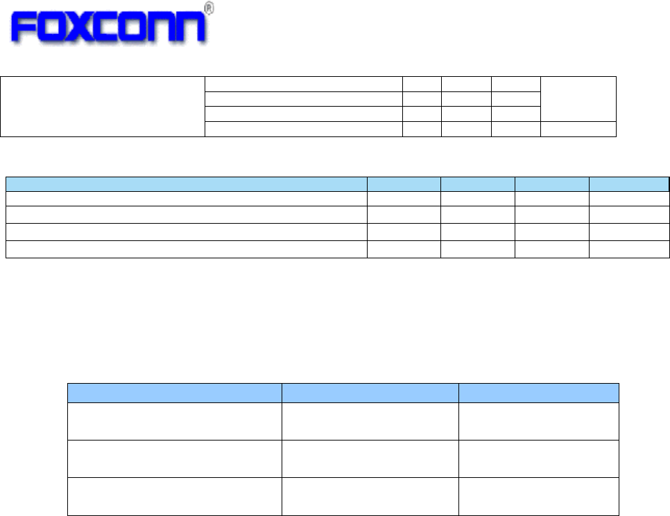
7.8 Antenna Electrical Specification(J20H085.01)
-
R
X Characteristics
-
Min.
Typ.
Max.
Unit
1
. Minimum Input Level Sensitivity
GFSK (1Mbps)
-
-
88
-
79
dB
m
π/4 DQPSK
(2Mbps)
-
-
88
-
79
dB
m
8DPSK (3Mbps)
-
-
8
4
-
7
6
dB
m
Parameter Value Units
Operating frequency range 2.4 ~ 2.4835
5.15~5.85
GHz
Antenna gain (max) -0.4 @2.4GHz
1.12 @5GHz
dBi (ANT1)
Antenna gain (max) 0.28 @2.4GHz
0.9 @5GHz
dBi (ANT2)

20
8 Handling Notice
1) ESD
There are semiconductors on the module, please handle the module under ESD protected
and well-controlled environment (<1000V).
2) Storage and Usage Condition
1. Moisture barrier bag must be stored under 40℃, humidity under 90% RH, when the
moisture barrier bag is sealed by Foxconn.
2. The calculated shelf life for the dry packed product shall be a 12 months from the bag
seal date.
3. If Moisture barrier bag is open, the component must be stored in an environment of
<25±5℃ /10%RH
9 4. Please keep the module at 30℃/70% RH.

21
17 Notification
When any change item happens in the product approval sheet, Foxconn will always inform
in advance and get approval by Sony.
Federal Communication Commission Interference Statement
This device complies with Part 15 of the FCC Rules. Operation is subject to the
following two conditions: (1) This device may not cause harmful interference, and
(2) this device must accept any interference received, including interference that
may cause undesired operation.
This equipment has been tested and found to comply with the limits for a Class B
digital device, pursuant to Part 15 of the FCC Rules. These limits are designed to
provide reasonable protection against harmful interference in a residential
installation. This equipment generates, uses and can radiate radio frequency energy
and, if not installed and used in accordance with the instructions, may cause
harmful interference to radio communications. However, there is no guarantee that
interference will not occur in a particular installation. If this equipment does cause
harmful interference to radio or television reception, which can be determined by
turning the equipment off and on, the user is encouraged to try to correct the
interference by one of the following measures:
- Reorient or relocate the receiving antenna.
- Increase the separation between the equipment and receiver.
- Connect the equipment into an outlet on a circuit different from that
to which the receiver is connected.
- Consult the dealer or an experienced radio/TV technician for help.
FCC Caution: Any changes or modifications not expressly approved by the party
responsible for compliance could void the user's authority to operate this equipment.
This transmitter must not be co-located or operating in conjunction with any other
antenna or transmitter.
Radiation Exposure Statement:
This equipment complies with FCC radiation exposure limits set forth for an
uncontrolled environment. This equipment should be installed and operated with
minimum distance 20cm between the radiator & your body.

22
This device is intended only for OEM integrators under the following conditions:
1) The antenna must be installed such that 20 cm is maintained between the
antenna and users, and
2) The transmitter module may not be co-located with any other transmitter or
antenna.
As long as 2 conditions above are met, further transmitter test will not be required.
However, the OEM integrator is still responsible for testing their end-product for any
additional compliance requirements required with this module installed
IMPORTANT NOTE: In the event that these conditions can not be met (for example
certain laptop configurations or co-location with another transmitter), then the FCC
authorization is no longer considered valid and the FCC ID can not be used on the
final product. In these circumstances, the OEM integrator will be responsible for
re-evaluating the end product (including the transmitter) and obtaining a separate
FCC authorization.
End Product
Labeling
This transmitter module is authorized only for use in device where the antenna may
be installed such that 20 cm may be maintained between the antenna and users.
The final end product must be labeled in a visible area with the following: “Contains
FCC ID: MCLJ20H085”. The grantee's FCC ID can be used only when all FCC
compliance requirements are met.
Manual Information To the End User
The OEM integrator has to be aware not to provide information to the end user
regarding how to install or remove this RF module in the user’s manual of the end
product which integrates this module.
The end user manual shall include all required regulatory information/warning as
show in this manual.
Industry Canada statement:
This device complies with RSS-210 of the Industry Canada Rules. Operation is subject to
the following two conditions: (1) This device may not cause harmful interference, and (2)
this device must accept any interference received, including interference that may cause
undesired operation.
Ce dispositif est conforme à la norme CNR-210 d'Industrie Canada applicable aux
appareils radio exempts de licence. Son fonctionnement est sujet aux deux conditions
suivantes: (1) le dispositif ne doit pas produire de brouillage préjudiciable, et (2) ce
dispositif doit accepter tout brouillage reçu, y compris un brouillage susceptible de
provoquer un fonctionnement indésirable.
Radiation Exposure Statement:
This equipment complies with IC radiation exposure limits set forth for an uncontrolled
environment. This equipment should be installed and operated with minimum distance
20cm between the radiator & your body.

23
Déclaration d'exposition aux radiations:
Cet équipement est conforme aux limites d'exposition aux rayonnements IC établies pour
un environnement non contrôlé. Cet équipement doit être installé et utilisé avec un
minimum de 20 cm de distance entre la source de rayonnement et votre corps.
This device is intended only for OEM integrators under the following conditions:
1) The antenna must be installed such that 20 cm is maintained between the antenna and
users, and
2) The transmitter module may not be co-located with any other transmitter or antenna.
As long as 2 conditions above are met, further transmitter test will not be required.
However, the OEM integrator is still responsible for testing their end-product for any
additional compliance requirements required with this module installed.
Cet appareil est conçu uniquement pour les intégrateurs OEM dans les conditions suivantes:
(Pour utilisation de dispositif module)
1) L'antenne doit être installée de telle sorte qu'une distance de 20 cm est respectée entre
l'antenne et les utilisateurs, et
2) Le module émetteur peut ne pas être coïmplanté avec un autre émetteur ou antenne.
Tant que les 2 conditions ci-dessus sont remplies, des essais supplémentaires sur
l'émetteur ne seront pas nécessaires. Toutefois, l'intégrateur OEM est toujours
responsable des essais sur son produit final pour toutes exigences de conformité
supplémentaires requis pour ce module installé.
IMPORTANT NOTE:
In the event that these conditions can not be met (for example certain laptop configurations
or co-location with another transmitter), then the Canada authorization is no longer
considered valid and the IC ID can not be used on the final product. In these
circumstances, the OEM integrator will be responsible for re-evaluating the end product
(including the transmitter) and obtaining a separate Canada authorization.
NOTE IMPORTANTE:
Dans le cas où ces conditions ne peuvent être satisfaites (par exemple pour certaines
configurations d'ordinateur portable ou de certaines co-localisation avec un autre
émetteur), l'autorisation du Canada n'est plus considéré comme valide et l'ID IC ne peut
pas être utilisé sur le produit final. Dans ces circonstances, l'intégrateur OEM sera chargé
de réévaluer le produit final (y compris l'émetteur) et l'obtention d'une autorisation distincte
au Canada.
End Product Labeling
This transmitter module is authorized only for use in device where the antenna may be
installed such that 20 cm may be maintained between the antenna and users. The final
end product must be labeled in a visible area with the following: “Contains IC:
2878D-J20H085”.
Plaque signalétique du produit final
Ce module émetteur est autorisé uniquement pour une utilisation dans un dispositif où

24
l'antenne peut être installée de telle sorte qu'une distance de 20cm peut être maintenue
entre l'antenne et les utilisateurs. Le produit final doit être étiqueté dans un endroit visible
avec l'inscription suivante: "Contient des IC: 2878D-J20H085".
Manual Information To the End User
The OEM integrator has to be aware not to provide information to the end user regarding
how to install or remove this RF module in the user’s manual of the end product which
integrates this module.
The end user manual shall include all required regulatory information/warning as show in
this manual.
Manuel d'information à l'utilisateur final
L'intégrateur OEM doit être conscient de ne pas fournir des informations à l'utilisateur final
quant à la façon d'installer ou de supprimer ce module RF dans le manuel de l'utilisateur
du produit final qui intègre ce module.
Le manuel de l'utilisateur final doit inclure toutes les informations réglementaires requises
et avertissements comme indiqué dans ce manuel.
Caution :
(i) the device for operation in the band 5150-5250 MHz is only for indoor use to reduce the
potential for harmful interference to co-channel mobile satellite systems;
(ii) the maximum antenna gain permitted for devices in the bands 5250-5350 MHz and
5470-5725 MHz shall comply with the e.i.r.p. limit; and
(iii) the maximum antenna gain permitted for devices in the band 5725-5825 MHz shall
comply with the e.i.r.p. limits specified for point-to-point and non point-to-point operation as
appropriate.
(iv) Users should also be advised that high-power radars are allocated as primary users
(i.e. priority users) of the bands 5250-5350 MHz and 5650-5850 MHz and that these radars
could cause interference and/or damage to LE-LAN devices.
Avertissement:
Le guide d’utilisation des dispositifs pour réseaux locaux doit inclure des instructions
précises sur les restrictions susmentionnées, notamment :
(i) les dispositifs fonctionnant dans la bande 5 150-5 250 MHz sont réservés uniquement
pour une utilisation à l’intérieur afin de réduire les risques de brouillage préjudiciable aux
systèmes de satellites mobiles utilisant les mêmes canaux;
(ii) le gain maximal d’antenne permis pour les dispositifs utilisant les bandes 5 250-5 350
MHz et 5 470-5 725 MHz doit se conformer à la limite de p.i.r.e.;
(iii) le gain maximal d’antenne permis (pour les dispositifs utilisant la bande 5 725-5 825
MHz) doit se conformer à la limite de p.i.r.e. spécifiée pour l’exploitation point à point et
non point à point, selon le cas.
(iv) De plus, les utilisateurs devraient aussi être avisés que les utilisateurs de radars de
haute puissance sont désignés utilisateurs principaux (c.-à-d., qu’ils ont la priorité) pour les
bandes 5 250-5 350 MHz et 5 650-5 850 MHz et que ces radars pourraient causer du
brouillage et/ou des dommages aux dispositifs LAN-EL.

25
Europe – EU Declaration of Conformity
This device complies with the essential requirements of the R&TTE Directive 1999/5/EC. The
following test methods have been applied in order to prove presumption of conformity
with the essential requirements of the R&TTE Directive 1999/5/EC:
- EN 60950-1/A12: 2011
Safety of Information Technology Equipment
- EN 62311: 2008 / Article 3(1)(a) and Article 2 2006/95/EC)
Assessment of electronic and electrical equipment related to human exposure
restrictions for electromagnetic fields (0 Hz-300 GHz) (IEC 62311:2007 (Modified))
- EN 300 328 V1.8.1: 2012
Electromagnetic compatibility and Radio spectrum Matters (ERM); Wideband
Transmission systems; Data transmission equipment operating in the 2,4 GHz ISM band
and using spread spectrum modulation techniques; Harmonized EN covering essential
requirements under article 3.2 of the R&TTE Directive
- EN 301 893 V1.7.1: 2012
Broadband Radio Access Networks (BRAN); 5 GHz high performance RLAN;
Harmonized EN covering essential requirements of article 3.2 of the R&TTE Directive
- EN 301 489-1 V1.9.2: 2011
Electromagnetic compatibility and Radio Spectrum Matters (ERM); ElectroMagnetic
Compatibility (EMC) standard for radio equipment and services; Part 1: Common
technical requirements
- EN 301 489-17 V2.2.1: 2012
Electromagnetic compatibility and Radio spectrum Matters (ERM); ElectroMagnetic
Compatibility (EMC) standard for radio equipment and services; Part 17: Specific
conditions for 2,4 GHz wideband transmission systems and 5 GHz high performance
RLAN equipment
Česky
[Czech]
[Jméno výrobce] tímto prohlašuje, že tento [typ zařízení] je ve shodě se základními požadavky a
dalšími příslušnými ustanoveními směrnice 1999/5/ES.
Dansk
[Danish]
Undertegnede [fabrikantens navn] erklærer herved, at følgende udstyr [udstyrets typebetegnelse]
overholder de væsentlige krav og øvrige relevante krav i direktiv 1999/5/EF.
Deutsch
[German]
Hiermit erklärt [Name des Herstellers], dass sich das Gerät [Gerätetyp] in Übereinstimmung mit den
grundlegenden Anforderungen und den übrigen einschlägigen Bestimmungen der Richtlinie
1999/5/EG befindet.
Eesti
[Estonian]
Käesolevaga kinnitab [tootja nimi = name of manufacturer] seadme [seadme tüüp = type of
equipment] vastavust direktiivi 1999/5/EÜ põhinõuetele ja nimetatud direktiivist tulenevatele teistele
asjakohastele sätetele.
English
Hereby, [name of manufacturer], declares that this [type of equipment] is in compliance with the
essential requirements and other relevant provisions of Directive 1999/5/EC.
Español
[Spanish]
Por medio de la presente [nombre del fabricante] declara que el [clase de equipo] cumple con
los requisitos esenciales y cualesquiera otras disposiciones aplicables o exigibles de la Directiva
1999/5/CE.
Ελληνική
[Greek]
ΜΕ ΤΗΝ ΠΑΡΟΥΣΑ [name of manufacturer] ∆ΗΛΩΝΕΙ ΟΤΙ [type of equipment] ΣΥΜΜΟΡΦΩΝΕΤΑΙ
ΠΡΟΣ ΤΙΣ ΟΥΣΙΩ∆ΕΙΣ ΑΠΑΙΤΗΣΕΙΣ ΚΑΙ ΤΙΣ ΛΟΙΠΕΣ ΣΧΕΤΙΚΕΣ ∆ΙΑΤΑΞΕΙΣ ΤΗΣ Ο∆ΗΓΙΑΣ 1999/5/ΕΚ.
Français
Par la présente [nom du fabricant] déclare que l'appareil [type d'appareil] est conforme aux

26
[French]
exigences essentielles et aux autres dispositions pertinentes de la directive 1999/5/CE.
Italiano
[Italian]
Con la presente [nome del costruttore] dichiara che questo [tipo di apparecchio] è conforme ai
requisiti essenziali ed alle altre disposizioni pertinenti stabilite dalla direttiva 1999/5/CE.
Latviski
[Latvian]
Ar šo [name of manufacturer / izgatavotāja nosaukums] deklarē, ka [type of equipment / iekārtas
tips] atbilst Direktīvas 1999/5/EK būtiskajām prasībām un citiem ar to saistītajiem noteikumiem.
Lietuvių
[Lithuanian]
Šiuo [manufacturer name] deklaruoja, kad šis [equipment type] atitinka esminius re
ikalavimus ir kitas
1999/5/EB Direktyvos nuostatas.
Nederlands
[Dutch]
Hierbij verklaart [naam van de fabrikant] dat het toestel [type van toestel] in overeenstemming is
met de essentiële eisen en de andere relevante bepalingen van richtlijn 1999/5/EG.
Malti
[Maltese]
Hawnhekk, [isem tal-manifattur], jiddikjara li dan [il-mudel tal-prodott] jikkonforma mal-ħtiġijiet
essenzjali u ma provvedimenti oħrajn relevanti li hemm fid-Dirrettiva 1999/5/EC.
Magyar
[Hungarian]
Alulírott, [gyártó neve] nyilatkozom, hogy a [... típus] megfelel a vonatkozó alapvetõ
követelményeknek és az 1999/5/EC irányelv egyéb elõírásainak.
Polski
[Polish]
Niniejszym [nazwa producenta] oświadcza, że [nazwa wyrobu] jest zgodny z zasadniczymi
wymogami oraz pozostałymi stosownymi postanowieniami Dyrektywy 1999/5/EC.
Português
[Portuguese]
[Nome do fabricante] declara que este [tipo de equipamento] está conforme com os requisitos
essenciais e outras disposições da Directiva 1999/5/CE.
Slovensko
[Slovenian]
[Ime proizvajalca] izjavlja, da je ta [tip opreme] v skladu z bistvenimi zahtevami in ostalimi
relevantnimi določili direktive 1999/5/ES.
Slovensky
[Slovak]
[Meno výrobcu] týmto vyhlasuje, že [typ zariadenia] spĺňa základné požiadavky a všetky príslušné
ustanovenia Smernice 1999/5/ES.
Suomi
[Finnish]
[Valmistaja = manufacturer] vakuuttaa täten että [type of equipment = laitteen tyyppimerkintä]
tyyppinen laite on direktiivin 1999/5/EY oleellisten vaatimusten ja sitä koskevien direktiivin muiden
ehtojen mukainen.
Svenska
[Swedish]
Härmed intygar [företag] att denna [utrustningstyp] står I överensstämmelse med de väsentliga
egenskapskrav och övriga relevanta bestämmelser som framgår av direktiv 1999/5/EG.
低功率電波輻射性電機管理辦法
低功率電波輻射性電機管理辦法低功率電波輻射性電機管理辦法
低功率電波輻射性電機管理辦法
第十二條 經型式認證合格之低功率射頻電機,非經許可,公司、商號或使用者
均不得擅自變更頻率、加大功率或變更原設計之特性及功能。
第十四條 低功率射頻電機之使用不得影響飛航安全及干擾合法通信;經發現有
干擾現象時,應立即停用,並改善至無干擾時方得繼續使用。
前項合法通信,指依電信法規定作業之無線電通信。
低功率射頻電機須忍受合法通信或工業、科學及醫療用電波輻射性電機
設備之干擾。

27
在5.25-5.35秭赫頻帶內操作之無線資訊傳輸設備,限於室內使用。
1. 本模組於取得認證後將依規定於模組本體標示審驗合格標籤。
2. 系統廠商應於平台上標示「本產品內含射頻模組: XXXyyyLPDzzzz-x」字
樣。