HON HAI PRECISION IND M26H002 WIFI/BT Combo wireless module User Manual M26H002
HON HAI Precision Ind. Co., Ltd. WIFI/BT Combo wireless module M26H002
M26H002_user manual

COMPANY CONFIDENTIAL
1
IEEE 802.11b/g/n WLAN and Bluetooth Combo Card
Project Name Marvell 88W8787 WLAN/BT Combo Card
Customer --
Foxconn Part No. M26H002
Customer Part No. --
HON HAI PRECISION IND. CO., LTD.
No.2, 2nd Dong Huan Road, 10th
YouSong lndustrial District, Longhua
Town, Baoan, ShenZhen
Tel: +86-755-28128988#26067
Fax:
+86
-
755
-
28129800#64886
User Manual

COMPANY CONFIDENTIAL
2
C
ONTENTS
0. REVISION HISTORY
1. INTRODUCTION
1.1
S
COPE
1.2
F
EATURE
2. PRODUCT SPECIFICATION
2.1
H
ARDWARE
S
PECIFICATION
2.2
M
ECHANICAL
S
PECIFICATION
2.2.1 Module Dimension
2.2.2 Host Interface Connector
2.2.3 RF Connector
3. ELECTRICAL SPECIFICATION
3.1
O
PERATING
C
ONDITION
3.2
W
I
F
I
RF
S
PECIFICATION
3.2.1 802.11b Mode
3.2.2 802.11g Mode
3.2.3 802.11n HT20 Mode
3.2.4 802.11n HT40 Mode
3.3
BT
RF
S
PECIFICATION
3.4
P
OWER
O
N
S
EQUENCE
3.5
SDIO
H
OST
I
NTERFACE
S
PECIFICATION
4. COMPLIANCE AND CERTIFICATION
4.1
FCC
C
OMPLIANCE

COMPANY CONFIDENTIAL
3
0. Revision History
Date Document
revision
Product
revision Change Description
2012/07/30
00 1. Initial release
2012/10/19
01 1. Update the WiFi TX/RX performance
2. Add Label and package information

COMPANY CONFIDENTIAL
4
1. Introduction
Project Name: Marvell 88W8787 WLAN/BT Combo Card
Project Number: M26H002
This documentation describes the engineering requirements specification of 88W8787
(WLAN+BT) combo Card. It is a confidential document of Foxconn.
1.1 Scope
This combo design is based on the Marvell 8787 single-chip solution. It’s operating in
2.4GHz, compatible with the IEEE 802.11b/g/n standard and Bluetooth BT2.1+EDR
standard. The 802.11n data rate provides for MCS0 to MCS7 (HT20,HT40). The 802.11g
data rate provides for 54, 48, 36, 24, 18, 12, 9, 6Mbps, and 802.11b data rate provides for
11, 5.5, 2, 1Mbps. In addition, it’s also compatible with BT2.1+EDR. This combo card has
implemented some efficient mechanisms in its software and hardware to maximize the
performance of WLAN and BT.
1.2 Feature
Marvell 88W8787 combo card with B2B connector
Compatible with IEEE 802.11b/g/n standard
Compatible with BT2.1+EDR standard,also compatible with BTv3.0+HS
Two U.FL RF connectors (one for WiFi, the other one for BT)
Support 11n HT20/HT40 mode
WLAN/BT data transactions are handled over SDIO interface
Support Wireless multimedia enhancements quality of service support (QoS)
Support WEP,TKIP, and AES hardware encryption
GP compliance

COMPANY CONFIDENTIAL
5
2. Product Specification
2.1 Hardware Specification
WLAN Features
Marvell’s 88W8787 is the IC of choice for the WLAN module with the following basic
features enabled:
Single band: 2.4GHz
802.11e (Quality of Service)
802.11i (Enhanced Security)
High Throughput 20MHz channel
High Throughput 40MHz channel
Mixed Format
Greenfield Format
Short Guard Interval
STA and AP concurrency
Bluetooth Features
Marvell’s 88W8787 as the IC of choice for the Bluetooth module with the following features
enabled:
Bluetooth 2.1 + EDR
Bluetooth 3.0 with Unicast Connectionless Data (UCD)
All Bluetooth-Host transactions will be done via the SDIO interface.
In other words, there will be no supported to use the UART, I2C, I2S, or PCM
interfaces.
The following profiles are anticipated for Bluetooth.
Human Interface Device (HID)
Headset Profile (HSP)
Hands-Free Profile (HFP)
Audio/Video Remote Control Profile (AVRCP)
Advanced Audio Distribution Profile (A2DP)
COMPANY CONFIDENTIAL
6
2.2 Mechanical Specification
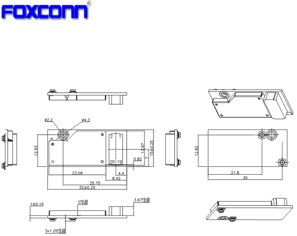
2.2.1 Module Dimension
PCB: FR4, 4layers, double side design
Typical PCB size (W×L): 15mm ×32mm.
Unit: mm
2.2.2 Host Interface Connector
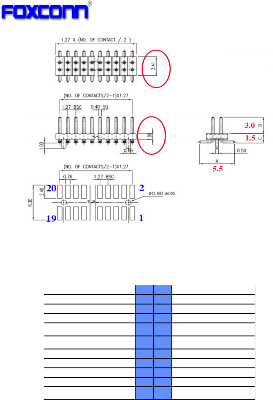
This module use 20 pins BTB connector for the Host-Module interface.
1.2mm Dual Row Pin header, SMT, 2x10Pin
COMPANY CONFIDENTIAL
7
Here is the pin-out signals of module’s connector. The pin number is refer to
“Item2.2.1 module dimension”.
Table 1: Host-Module Connector Pin-out Signals
Pin-Out No.
No.
Pin-Out
3V3 1 2 SD_CLK
3V3 3 4 GND
GND 5 6 SD_D0
RESET# 7 8 SD_D1
SLEEP_CLK (32.768kHz) 9 10 GND
GND 11 12 SD_D2
SD_CMD 13 14 SD_D3
PDn 15 16 GND
GND 17 18 HOST_WAKEUP_DEV
VIO 19 20 VIO
*Note, Pin18[HOST_WAKEUP_DEV] of connector is connected with the pinM11[GPIO4] of 88W8787
TFBGA IC. It can be configured to IO input or IO output for wake-up application.
COMPANY CONFIDENTIAL
8
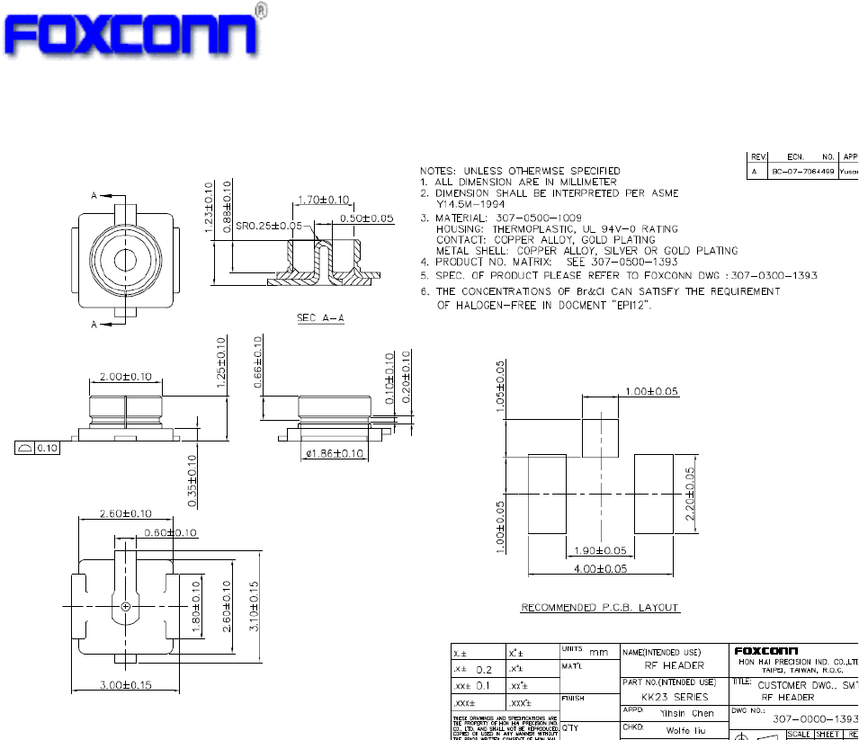
2.2.3 RF Connector
This module use U.F.L type RF connector for external WiFi/BT antenna connecting.
COMPANY CONFIDENTIAL
9
3. Electrical Specification
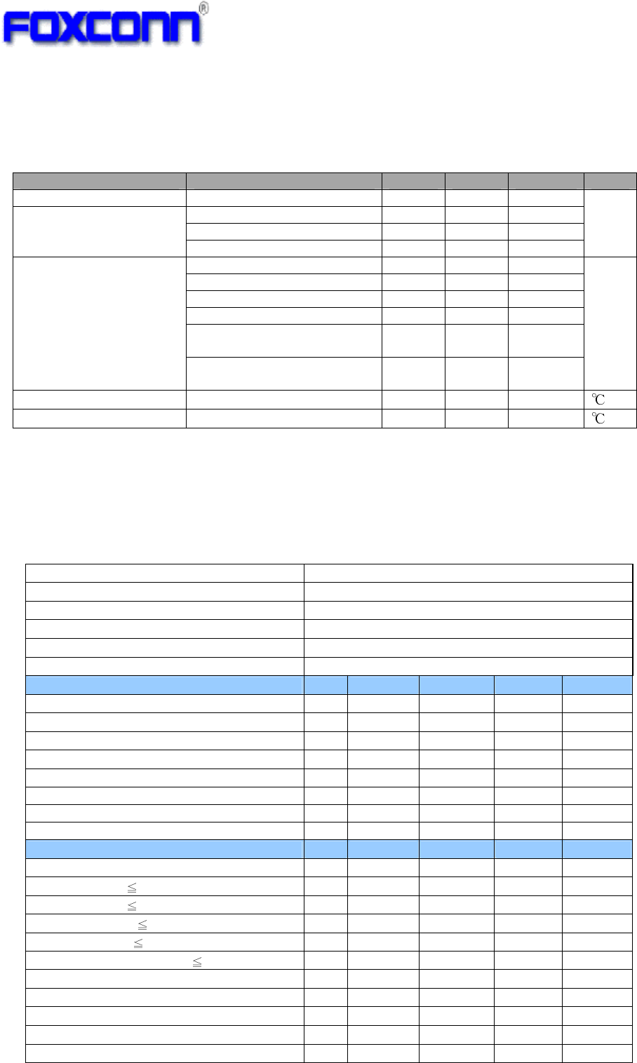
3.1 Operating Condition
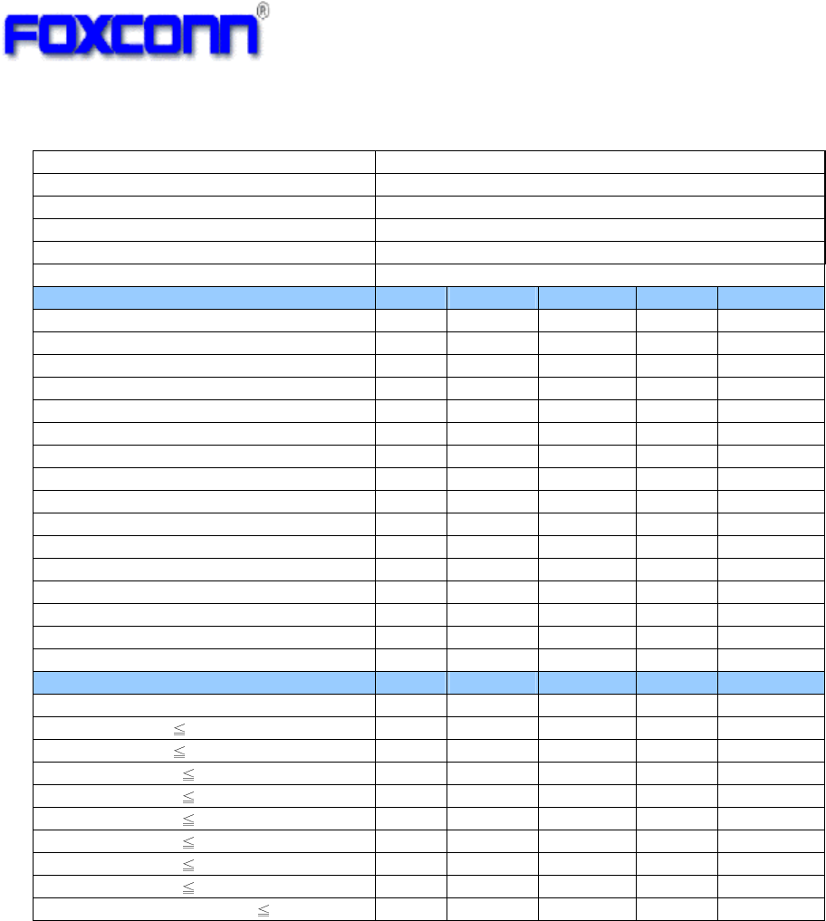
Parameter Condition Min. Typ. Max. Unit
DC Input 3.3V 3.135 3.3 3.465
3.3 2.97 3.3 3.63
2.6 2.5 2.6 2.7
VIO Input(Note1)
1.8 1.62 1.8 1.98
V
WiFi TX only and BT sleep 214
WiFi RX only and BT sleep 168
BT TX only 29
BT RX only 24
WiFi/BT co-existence
(wifi will run at 20MHz BW)
187
Module Current
(DC input nominal)
Standby
with connection AP
30
mA
Operating Temperature -- 0 +65
Storage Temperature -- -10 +85
Note1:Digital I/O power supply ,VIO pin should be connected to the same supply which drivers the SDIO
interface of the host processor
3.2 WiFi RF Specification
3.2.1 802.11b Mode
Items Contents
Standard IEEE802.11b
Modulation Type DSSS / CCK
Frequency range 2400MHz~2483.5MHz
Channel CH1 to CH13
Data rate 1, 2, 5.5, 11Mbps
TX Characteristics Min.
Typ. Max. Unit
1. Transmitter Output Power
1) 11b Target Power(average) 15.5
17 18.5 dBm
2. Spectrum Mask @ target power
1) fc +/-11MHz to +/-22MHz - - -30 dBr
2) fc > +/-22MHz - - -50 dBr
3. Frequency Error -25 -1 +25 ppm
4 Constellation Error( peak EVM)@ target power
1) 1~11Mbps - -35dB
RX Characteristics Min.
Typ. Max. Unit
5 Minimum Input Level Sensitivity
1) 1Mbps (FER 8%) - -97 -83 dBm
2) 2Mbps (FER 8%) - -94 -80 dBm
3) 5.5Mbps (FER 8%) - -91 -79 dBm
4) 11Mbps (FER 8%) - -88 -76 dBm
6 Maximum Input Level (FER 8%) -10 - - dBm
COMPANY CONFIDENTIAL
10
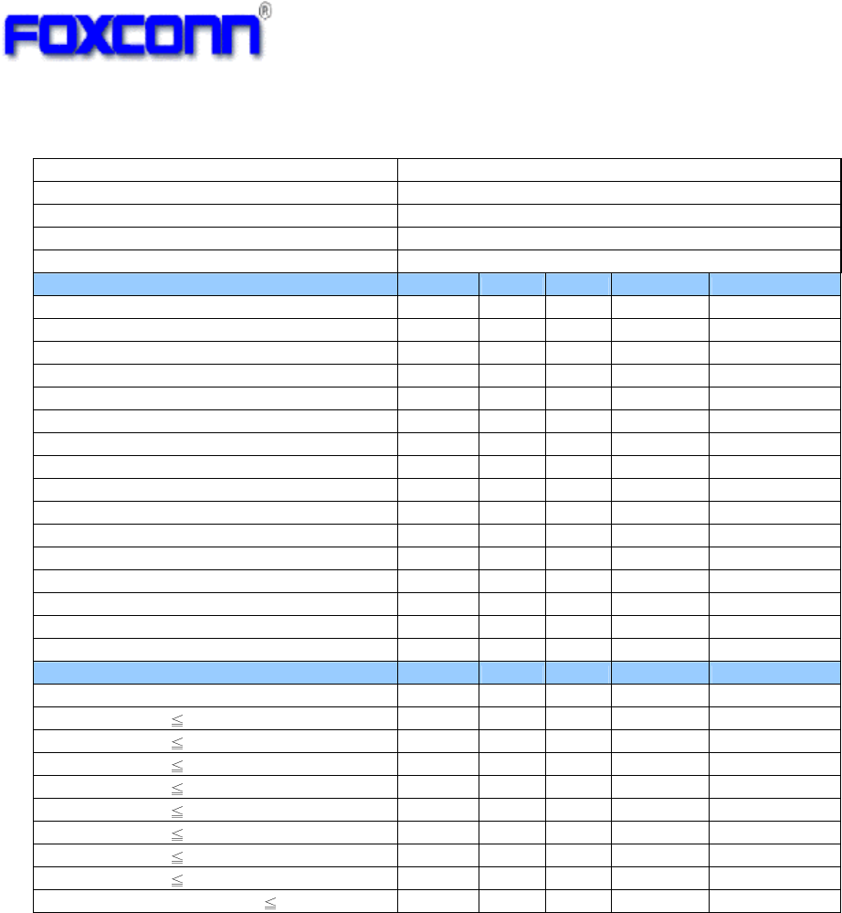
3.2.2 802.11g Mode
Items Contents
Standard IEEE802.11g
Modulation Type OFDM
Frequency range 2400MHz~2483.5MHz
Channel CH1 to CH13
Data rate 6, 9, 12, 18, 24, 36, 48, 54Mbps
TX Characteristics Min. Typ. Max. Unit
1. Transmitter Output Power
1) 11g Target Power(average) 13.5 15 16.5 dBm
2. Spectrum Mask @ target power
1) at fc +/- 11MHz - - -20 dBr
2) at fc +/- 20MHz - - -28 dBr
3) at fc > +/-30MHz - - -40 dBr
3 Constellation Error(EVM)@ target power
1) 6Mbps - -31 -5 dB
2) 9Mbps - -31 -8 dB
3) 12Mbps - -30 -10 dB
4) 18Mbps - -31 -13 dB
5) 24Mbps - -29 -16 dB
6) 36Mbps - -30 -19 dB
7) 48Mbps - -31 -22 dB
8) 54Mbps - -30 -25 dB
4 Frequency Error -25 -1.1 +25 ppm
RX Characteristics Min. Typ. Max. Unit
5 Minimum Input Level Sensitivity
1) 6Mbps (PER 10%) - -90 -85 dBm
2) 9Mbps (PER 10%) - -89 -84 dBm
3) 12Mbps (PER 10%) - -88 -82 dBm
4) 18Mbps (PER 10%) - -86 -80 dBm
5) 24Mbps (PER 10%) - -83 -77 dBm
6) 36Mbps (PER 10%) - -80 -73 dBm
7) 48Mbps (PER 10%) - -75 -69 dBm
8) 54Mbps (PER 10%) - -74 -68 dBm
6 Maximum Input Level (PER 10%) -20 - dBm
COMPANY CONFIDENTIAL
11
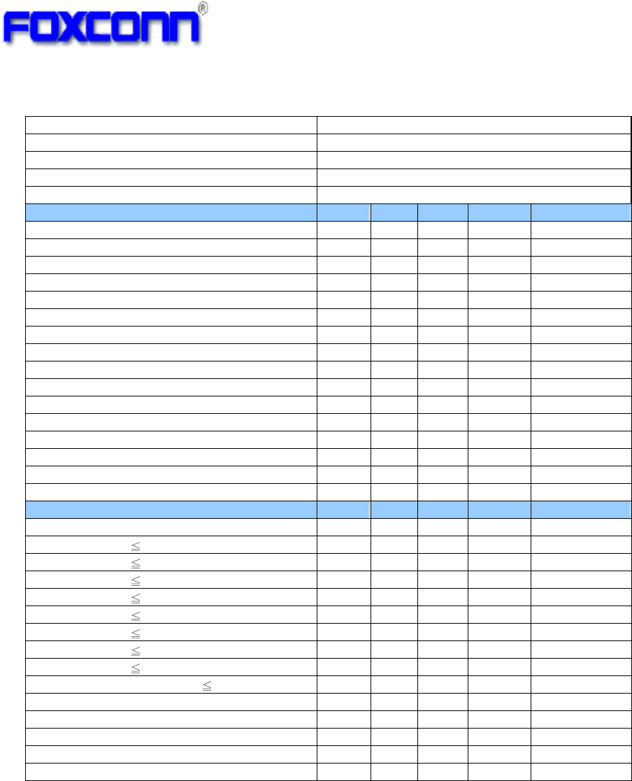
3.2.3 802.11n HT20 Mode
Items
Contents
Standard IEEE802.11n HT20 @ 2.4GHz
Modulation type MIMO-OFDM
Channel CH1 to CH13
Data rate (MCS index) MCS0/1/2/3/4/5/6/7
TX Characteristics Min. Typ. Max.
Unit
1. Transmitter Output Power
1) 11n HT20 Target Power(average)
12.5 14 15.5 dBm
2. Spectrum Mask @ target power
1) at fc +/- 11MHz - - -20 dBr
2) at fc +/- 20MHz - - -28 dBr
3) at fc > +/-30MHz - - -45 dBr
3. Constellation Error(EVM)@ target power
1) MCS0 - -31 -5 dB
2) MCS1 - -31 -10 dB
3) MCS2 - -31 -13 dB
4) MCS3 - -31 -16 dB
5) MCS4 - -31 -19 dB
6) MCS5 - -30 -22 dB
7) MCS6 - -31 -25 dB
8) MCS7 - -30 -28 dB
4. Frequency Error -25 -1.2 +25 ppm
RX Characteristics Min. Typ. Max.
Unit
5. Minimum Input Level Sensitivity
1) MCS0 (PER 10%) - -89 -82 dBm
2) MCS1 (PER 10%) - -87 -79 dBm
3) MCS2 (PER 10%) - -85 -77 dBm
4) MCS3 (PER 10%) - -82 -74 dBm
5) MCS4 (PER 10%) - -78 -70 dBm
6) MCS5 (PER 10%) - -74 -66 dBm
7) MCS6 (PER 10%) - -72 -65 dBm
8) MCS7 (PER 10%) - -71 -64 dBm
6. Maximum Input Level (PER 10%) -20 - dBm
COMPANY CONFIDENTIAL
12
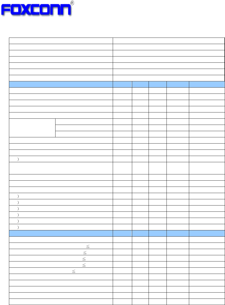
3.2.4 802.11n HT40 Mode
Items
Contents
Standard IEEE802.11n HT40 @ 2.4GHz
Modulation type MIMO-OFDM
Channel CH3 to CH11
Data rate (MCS index) MCS0/1/2/3/4/5/6/7
TX Characteristics Min. Typ.
Max.
Unit
1. Transmitter Output Power
1) 11n HT40 Target power(average)
12.5 14 15.5 dBm
2. Spectrum Mask @ target power
1) at fc +/- 22MHz - - -20 dBr
2) at fc +/- 40MHz - - -28 dBr
3) at fc > +/-60MHz - - -45 dBr
3. Constellation Error(EVM)@target power
1) MCS0 - -33 -5 dB
2) MCS1 - -32 -10 dB
3) MCS2 - -32 -13 dB
4) MCS3 - -32 -16 dB
5) MCS4 - -32 -19 dB
6) MCS5 - -32 -22 dB
7) MCS6 - -33 -25 dB
8) MCS7 - -33 -28 dB
4. Frequency Error -25 -1.3
+25 ppm
RX Characteristics Min. Typ.
Max.
Unit
5. Minimum Input Level Sensitivity
1) MCS0 (PER 10%) - -87 -79 dBm
2) MCS1 (PER 10%) - -84 -76 dBm
3) MCS2 (PER 10%) - -82 -74 dBm
4) MCS3 (PER 10%) - -79 -71 dBm
5) MCS4 (PER 10%) - -75 -67 dBm
6) MCS5 (PER 10%) - -71 -63 dBm
7) MCS6 (PER 10%) - -70 -62 dBm
8) MCS7 (PER 10%) - -68 -61 dBm
6. Maximum Input Level (PER 10%) -20 - dBm
COMPANY CONFIDENTIAL
13
3.3 BT RF Specification
Items
Contents
Standard BTv2.1+EDR
Modulation technology HFSS
Modulation type GFSK, π/4-DQPSK, 8DPSK
Frequency range 2402MHz ~ 2480MHz
Numbers of Channel
79 channels with 1MHz Bandwidth
Data rate 1Mbps/2Mbps/3Mbps
TX Characteristics Min. Typ.
Max.
Unit
1. BDR
Transmitter Output Power
1) Target power (class2)(average)
-6 2.0 +4 dBm
2. BDR Initial Carrier Freq. Tolerance
-75 -1.3
+75 KHz
3. BDR Carrier Drift
1)
Drift Rate/50us
-20 4.7 +20 KHz
DH1 -25 -1 +25 dB
DH3 -40 +2 +40 KHz
2) Average
Drift
DH5 -40 0 +40 KHz
4. BDR Modulation Characteristic
1) F1avg(kHz) 140 162.1
175 KHz
2) F2avg(kHz) 115 146.5
- KHz
3 F1/F2 Ratio 0.8 0.9 - -
5 EDR Carrier Frequency Stability and
Modulation Accuracy
1) Initial Frequency Error -75 -1.3
+75 KHz
2) Frequency Error -10 0.6 +10 KHz
3) Block Frequency Error -75 -1.2
+75 KHz
4 RMS DEVM @2Mbps 0.2 0.045
-
5 Peak DEVM @2Mbps 0.35 0.1 -
6
99% DEVM
@
% Symbols <= 0.3 (2Mbps) 99% 100%
-
7 RMS DEVM @3Mbps 0.13 0.037
-
8 Peak DEVM @3Mbps 0.25 0.08
-
9
99% DEVM
@
% Symbols <= 0.2(3Mbps) 99% 100%
-
RX Characteristics Min. Typ.
Max.
Unit
6. Minimum Input Level Sensitivity
1) BDR Single slot sensitivity (BER 0.1%) - -87 -70 dBm
2) BDR Multi slot sensitivity (BER 0.1%) - -87 -70 dBm
3) EDR sensitivity@2Mbps (BER 0.01%) - -86 -70 dBm
4) EDR sensitivity@3Mbps (BER 0.01%) - -77 -70 dBm
7. Maximum Input Level (BER 0.1%) -20 - dBm
COMPANY CONFIDENTIAL
14
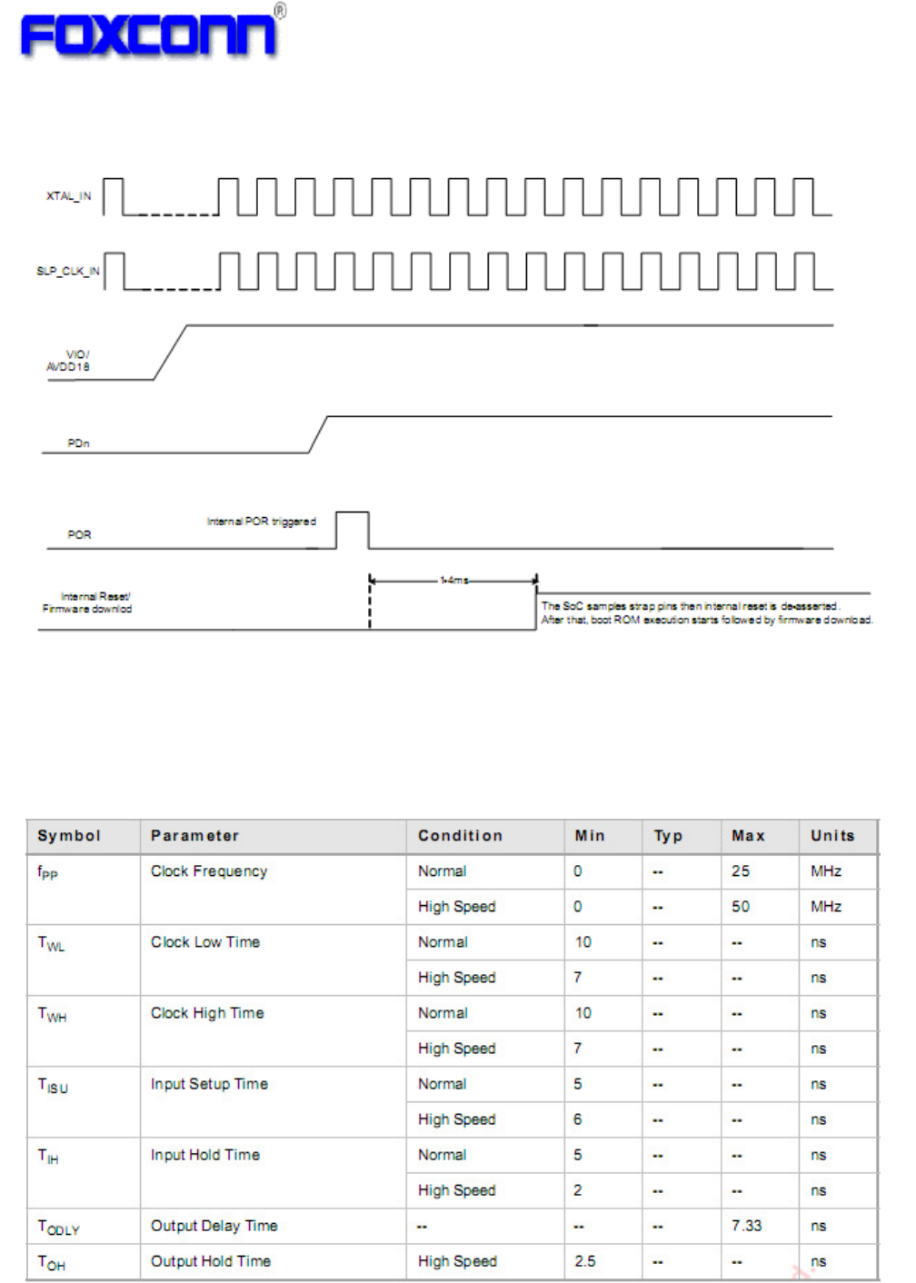
3.4 Power On Sequence
PDn must remain asserted for a minimum of 1ms after VIO,SLP_CLK and XTAL_IN
are stable.
For auto reference clock detection ,the sleep clock(32.768KHz) must be used and
must be stable before PDn is de-asserted.
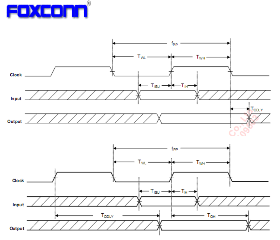
3.5 SDIO Host Interface Specification
Figure2 SDIO Timing Date
COMPANY CONFIDENTIAL
15
Figure3 SDIO Timing Diagram-Normal Mode
Figure4 SDIO Timing Diagram-High Speed Mode

COMPANY CONFIDENTIAL
16
4. Compliance and Certification
4.1 FCC Compliance
One of the main reasons for considering a PWB module is that the module is being
considered for multiple products, the ODM supplier perform FCC Part 15C (15.247) for
2.4GHz. The customer would be responsible for FCC Part 15B product compliance testing.
FCC Notice
Federal Communication Commission Interference Statement
This equipment has been tested and found to comply with the limits for a Class B digital
device, pursuant to Part 15 of the FCC Rules. These limits are designed to provide
reasonable protection against harmful interference in a residential installation. This
equipment generates, uses and can radiate radio frequency energy and, if not installed
and used in accordance with the instructions, may cause harmful interference to radio
communications. However, there is no guarantee that interference will not occur in a
particular installation. If this equipment does cause harmful interference to radio or
television reception, which can be determined by turning the equipment off and on, the
user is encouraged to try to correct the interference by one of the following measures:
- Reorient or relocate the receiving antenna.
- Increase the separation between the equipment and receiver.
- Connect the equipment into an outlet on a circuit different from that to which the
receiver is connected.
- Consult the dealer or an experienced radio/TV technician for help.
This device complies with Part 15 of the FCC Rules. Operation is subject to the following
two conditions: (1) This device may not cause harmful interference, and (2) this device
must accept any interference received, including interference that may cause undesired
operation.
FCC Caution: Any changes or modifications not expressly approved by the party
responsible for compliance could void the user's authority to operate this equipment.
IMPORTANT NOTE:
FCC Radiation Exposure Statement:
This equipment complies with FCC radiation exposure limits set forth for an uncontrolled
environment.
This transmitter must not be co-located or operating in conjunction with any other antenna
or transmitter.
FOXCONN declared that M26H002 is limited in CH1~11 from 2412 to 2462MHz by
specified firmware controlled in USA.
This device is intended only for OEM integrators under the following conditions:
The antenna must be installed such that 20 cm is maintained between the antenna and
users, and
The transmitter module may not be co-located with any other transmitter or antenna.
As long as 2 conditions above are met, further transmitter test will not be required.
However, the OEM integrator is still responsible for testing their end-product for any
additional compliance requirements required with this module installed (for example,
digital device emissions, PC peripheral requirements, etc.).

COMPANY CONFIDENTIAL
17
IMPORTANT NOTE: In the event that these conditions can not be met (for example
certain laptop configurations or co-location with another transmitter), then the FCC
authorization is no longer considered valid and the FCC ID can not be used on the final
product. In these circumstances, the OEM integrator will be responsible for re-evaluating
the end product (including the transmitter) and obtaining a separate FCC authorization.
End Product Labeling
This transmitter module is authorized only for use in device where the antenna may be
installed such that 20 cm may be maintained between the antenna and users. The final
end product must be labeled in a visible area with the following: “Contains TX FCC ID:
MCLM26H002”.
Manual Information That Must be Included
The OEM integrator has to be aware not to provide information to the end user
regarding how to install or remove this RF module in the users manual of the end
product which integrate this module.
The users manual for OEM integrators must include the following
information in a prominent location “ IMPORTANT NOTE: To comply
with FCC RF exposure compliance requirements, the antenna used for
this transmitter must be installed to provide a separation distance of at
least 20 cm from all persons and must not be co-located or operating in
conjunction with any other antenna or transmitter.