HON HAI PRECISION IND T77H134 WLAN & Bluetooth combo module User Manual UserMan MCLT77H134 revised
HON HAI Precision Ind. Co., Ltd. WLAN & Bluetooth combo module UserMan MCLT77H134 revised
UserMan_MCLT77H134-revised
.!2!.!
MARVELL 88W8688 Mini-Module
(IEEE 802.11b/g+BT 2.1 EDR)
Marketing Requirements Specification
T77H134.00
< REV.05>
Prepared by Reviewed by Approved by
Plum Feng Robin Xu Chang-fu Lin
WLAN & BT combo module
WLAN and Bluetooth
combo module

.!3!.!
CONTENTS
0.
REVISION HISTORY..............................................................................................................................................3
1. INTRODUCTION ..........................................................................................................................................................4
1.1
S
COPE
......................................................................................................................................................................4
1.2
F
UNCTION
.................................................................................................................................................................4
1.3
E
NVIRONMENTAL
......................................................................................................................................................4
2 PRODUCT SPECIFICATION ......................................................................................................................................5
2.1
H
ARDWARE
S
PECIFICATION
.....................................................................................................................................5
3. PRODUCT REQUIREMENTS ....................................................................................................................................6
3.1
H
ARDWARE
R
EQUIREMENTS
....................................................................................................................................6
3.2
H
ARDWARE
A
RCHITECTURE
....................................................................................................................................6
3.3
M
ECHANICAL OUTLINE
D
RAWING
.............................................................................................................................7
3.4
L
AND
G
RID
A
RRAY
...................................................................................................................................................8
3.5
S
OFTWARE
R
EQUIREMENTS
..................................................................................................................................10

.!4!.!
0. Revision History
Date Change Note REV Note
Nov. 11, 2008 Rev.01 0
Dec. 19, 2008 Rev.02
Update dimension of module
Apr. 28, 2009 Rev.03
Change the pin-define
Oct. 13.2009 Rev.04
Change the height of shielding
Oct. 27.2009 Rev.05
Change the mechanical spec of
shielding

.!5!.!
1. Introduction
Project Name: Mini-Module (802.11b/g + BT Module) based on Marvell IC 88W8688 with TFBGA
package.
This documentation describes the Engineering requirements specification of the WLAN
(802.11b/g) +Bluetooth 2.1 EDR Mini-Module. It is a confidential document of FOXCONN.
1.1 Scope
The Wireless MARVELL 88W8688BFL Mini-Module is designed to support 802.11g data rate of 54,
48, 36, 24, 18, 12, 9, 6Mbps, and as well as 802.11b data rate of 11, 5.5, 2, 1Mbps for WLAN
operation. In addition, this module is Bluetooth 2.1+Enhanced Data Rate (EDR) compliant which
provide 1, 2 and 3Mbps data rate.
1.2 Function
Ɣ Compatible with IEEE 802.11b/g standard and Bluetoothv2.1+EDR standard
Ɣ Ultra low-power dissipation
Ɣ Support external power down mode
Ɣ Support Marvell Wi-Fi/Bluetooth coexistence
Ɣ Support the IEEE 802.11i security standard through implementation of the Advanced Encryption
Standard (AES)/ Counter Mode CBC-Mac Protocol (CCMP) and WEP security mechanisms. Also
supports Internet Protocol Security (IPSce) with DES/3DES/AES encryption and MD5/SHA-1
authentication.
Ɣ Host interface supports for SDIO/ G-SPI, PCM/I2S Codec interface for multimedia application
Ɣ Host interface supports for SDIO/ G-SPI, PCM/I2S Codec interface for multimedia application
1.3 Environmental
Ambient Temperature (operation) = -10 to +75 Degrees Celsius.
Product storage temperature = -40 to +85 Degrees Celsius.

.!6!.!
2 Product Specification
2.1 Hardware Specification
2.1.1 WLAN
Wireless LAN Standards IEEE 802.11g standard and IEEE 802.11b
Operating Frequency 2.412~2.484GHz
Channel Numbers
11 channels for United States
13 channels for Europe Countries
14 channels for Japan
WLAN Data Rate 802.11g: 54Mbps with fall back of 48, 36, 24, 18, 12, 9, 6Mbps.
802.11b: 11Mbps with fall back rates of 5.5, 2, and 1Mbps
Modulation Schemes 802.11g:
64QAM (54Mbps, 48Mbps), 16QAM (36Mbps, 24Mbps), QPSK
(18Mbps, 12Mbps), BPSK (9Mbps, 6Mbps)
802.11b:
CCK (11 Mbps, 5.5Mbps), DQPSK (2 Mbps), DBPSK (1 Mbps)
Transmitter Output Power Typical 14dBm for 54, 48, 36, 24, 18, 12, 9, 6Mbps
Typical 15dBm for 11, 5.5, 2, 1Mbps
EVM 802.11b @11Mbps_14dBm (8%dB@peak)
802.11g @54Mbps_14dBm (-26dB@average)
Receiver Sensitivity Typical –72dBm for 54Mbps @ 10% PER
Typical –74dBm for 48Mbps @ 10% PER
Typical –81dBm for 36Mbps @ 10% PER
Typical –83dBm for 24Mbps @ 10% PER
Typical –86dBm for 18Mbps @ 10% PER
Typical –88dBm for 12Mbps @ 10% PER
Typical –88dBm for 9Mbps @ 10% PER
Typical –88dBm for 6Mbps @ 10% PER
Typical –88dBm for 11Mbps @ 8% PER
Typical –90dBm for 5.5Mbps @ 8% PER
Typical –92dBm for 2Mbps @ 8% PER
Typical –93dBm for 1Mbps @ 8% PER
Media Access Protocol CSMA/CA with ACK
2.1.2 Bluetooth
Radio Technology FHSS
Operating Frequency 2402 ~ 2480MHz ISM band
Channel Numbers 79 channels with 1MHz BW
Transmitter Output Power -6~ +4dBm output power for class2
Receiver Sensitivity -80dBm @ GFSK 0.1% BER, 1Mbps
Maximum Receiver Signal -20dBm
and Taiwan.
11b : 22 dBm
11g : 25 dBm
-
.!7!.!
3. Product Requirements
3.1 Hardware Requirements
Form factor LGA
Host Interface SDIO
PCB 6-layer FR4
Antenna port: One BT RF port and One Wi-Fi RF port
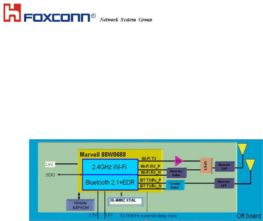
3.2 Hardware Architecture
The module design is based on the MARVELL 88W8688BFL single chip which implements
IEEE802.11b/g and Bluetooth 2.1+EDR.
Figure 1 Functional Block Diagram
MARVELL 88W8688BFL is a highly integrated, low-cost, low-power IEEE802.11 b/g MAC
/Baseband / RF WLAN and Bluetooth Baseband/RF. The mini Module apply to WLAN /Bluetooth
cellular handsets ,WLAN/Bluetooth headsets, portable audio/video devices and accessories ,
gaming platforms, and WLAN/Bluetooth enabled digital still cameras and printers.
The single chip MARVELL 88W8688BFL interfaces directly with both the RF and digital signals.
It transmits and receivers RF signals at 2.4GHz to and from the antenna and digital signals to and
from the host interface. A power management (PMU) is placed in the off Board to provide power
for all components in the module and also can save precious board space.

.!8!.!
3.3 Mechanical outline Drawing
The MARVELL 8688 Mini-Module 802.11b/g module shall be 6-layer PCB design.
Dimension (W×L×H): 10.8mm ×15.8mm ×2.1mm (max.)
(Bottom view)
Federal Communication Commission Interference Statement
This equipment has been tested and found to comply with the limits for a Class B digital device,
pursuant to Part 15 of the FCC Rules. These limits are designed to provide reasonable protection
against harmful interference in a residential installation. This equipment generates, uses and can
radiate radio frequency energy and, if not installed and used in accordance with the instructions,
may cause harmful interference to radio communications. However, there is no guarantee that
interference will not occur in a particular installation. If this equipment does cause harmful
interference to radio or television reception, which can be determined by turning the equipment of
f
and on, the user is encouraged to try to correct the interference by one of the following measures:
- Reorient or relocate the receiving antenna.
- Increase the separation between the equipment and receiver.
- Connect the equipment into an outlet on a circuit different from that
to which the receiver is connected.
- Consult the dealer or an experienced radio/TV technician for help.
This device complies with Part 15 of the FCC Rules. Operation is subject to the following two
conditions: (1) This device may not cause harmful interference, and (2) this device must accept
any interference received, including interference that may cause undesired operation.
FCC Caution: Any changes or modifications not expressly approved by the party responsible fo
r
compliance could void the user's authority to operate this equipment.
IMPORTANT NOTE:
FCC Radiation Exposure Statement:
This equipment complies with FCC radiation exposure limits set forth for an uncontrolled
environment. This equipment should be installed and operated with minimum distance 20cm
between the radiator & your body.
This transmitter must not be co-located or operating in conjunction with any other antenna o
r
transmitter.
IEEE 802.11b or 802.11g operation of this product in the U.S.A. is firmware-limited to channels 1
through 11.
This device is intended only for OEM integrators under the following conditions:
1) The antenna must be installed such that 20 cm is maintained between the antenna and users,
and
2) The transmitter module may not be co-located with any other transmitter or antenna,
3) For all products market in US, OEM has to limit the operation channels in CH1 to CH11 for 2.4G
band by supplied firmware programming tool. OEM shall not supply any tool or info to the end-use
r
regarding to Regulatory Domain change.
A
s long as 3 conditions above are met, further transmitter test will not be required. However, the
OEM integrator is still responsible for testing their end-product for any additional compliance
requirements required with this module installed (for example, digital device emissions, PC
peripheral requirements, etc.).
, except tested built-in WLAN-BT collocation.
This device is intended only for OEM integrators under the following conditions:
1) The antenna must be installed such that 20 cm is maintained between the antenna and users,
and
2) The transmitter module may not be co-located with any other transmitter or antenna, except tested
built-in WLAN-BT collocation.
3) For all products market in US, OEM has to limit the operation channels in CH1 to CH11 for 2.4G
band by supplied firmware programming tool. OEM shall not supply any tool or info to the end-user
regarding to Regulatory Domain change.
A
s long as 3 conditions above are met, further transmitter test will not be required. However, the
OEM integrator is still responsible for testing their end-product for any additional compliance
requirements required with this module installed (for example, digital device emissions, PC peripheral
requirements, etc.).
.!9!.!
3.4 Land Grid Array
3.4.1 LGA assignment and location˄
˄˄
˄top view˅
˅˅
˅
IMPORTANT NOTE: In the event that these conditions can not be met (for example certain
laptop configurations or co-location with another transmitter), then the FCC authorization is no
longer considered valid and the FCC ID can not be used on the final product. In these
circumstances, the OEM integrator will be responsible for re-evaluating the end product
(including the transmitter) and obtaining a separate FCC authorization.
End Product Labeling
This transmitter module is authorized only for use in device where the antenna may be installed
such that 20 cm may be maintained between the antenna and users. The final end product must
be labeled in a visible area with the following: “Contains FCC ID:MCLT77H134”.
Manual Information To the End User
The OEM integrator has to be aware not to provide information to the end user regarding how to
install or remove this RF module in the user's manual of the end product which integrates this
module.
The end user manual shall include all required regulatory information/warning as show in this
manual.

.!:!.!
3.4.2 Pin definition
Pin name PIN# Function
TCK C2 JTAG test clock input
TDI F4 JTAG test data input
TDO E3 JTAG test data output
TMS2 D4 JTAG test mode select. Selects the system JTAG controller
TRSTn C4 JTAG test reset(active low)
TMS E4
JTAG test mode select. Selects the internal CPU JTAG
controller
BT-PCM-DOUT E5 PCM data output signal
BT-PCM-MCLK E6
PCM clock signal (optional) Optional clock used for some
codecs. Derived from PCM_CLK
BT-PCM-CLK C8 PCM Clock Signal output if PCM master. Input if PCM slave
BT-PCM-DIN D6 PCM data input signal
BT-PCM-SYNC D5 PCM Sync Pulse Signal
WLAN-LED D1 LED for WLAN indicator light
GPIO17 B2
GPIO17 for BT LED(Wi-Fi IRQ)
GPIO17 default high for SDIO interface, pull low for G-SPI
interface
WLAN F8 Wi-Fi RF Signal
BT-OUT F1 BT RF Signal
EXT-SLEEP-CLK D8 clock input for external 32.768KHz sleep clock
VDD33 B7 3.3V voltage ,add at least 1uF cap bypass
VDD30 C7 3.0V voltage ,add at least 1uF cap bypass
VIO_X1 A2 1.8V or 3.3V voltage, add at least 1uF cap bypass
VIO_X2 D3 1.8V or 3.3V voltage, add at least 1uF cap bypass
SD-D3/SPI_CLK_REQ C1 SDIO data interface/G-SPI interface
SD-D2/SPI_SINTn A3 SDIO data interface/G-SPI interface
SD-D1/ SPI_SDO B3 SDIO data interface/G-SPI interface
SD-D0/SPI_SCSn C3 SDIO data interface/G-SPI interface
SD-CMD/ SPI_SDI A4 SDIO command/G-SPI interface
SD-CLK/SPI_CLK B4 SDIO clock/G-SPI Clock
CF-INPACK-N B6
PC card I/O mode input Acknowledge. Used by the card to
indicate to the host that the card is selected and is
responding to a read cycle.
WLAN-MAC-WAKE B1 Host to indicate to the card is selected
VDD18D C5 C6 1.8V voltage, add at least 1uF cap bypass
VDD18_LDO B5 1.8V voltage, add at least 1uF cap bypass
RESETn D7
Reset pin ,need external 100K res connected to 3.3 voltage
to pull high
PDn
D2
Full power down (active low).Have 100K res to pull this pin
high for normal operation in the module. No need external
pull-up for this pin
GPIO0 A7 NC for Reserve
GND
A1 A5 A6 A8
A9 B8 B9 C9
D9 E1 E2 E7
E8 E9 F2 F3
F5 F6 F7 F9
GND
NCC ᤞ :
ᆖীڤᎁᢞٽհ܅פ୴᙮ሽᖲΔॺᆖױΔֆΕᇆࢨࠌشृ݁լᖐ۞᧢ޓ᙮Εף!!!
Օפࢨ᧢ޓૠհࢤ֗פ౨Ζ
܅פ୴᙮ሽᖲհࠌشլᐙଆڜ٤֗եឫٽऄຏॾΙᆖ࿇ڶեឫွழΔᚨمܛೖشΔࠀ
ޏ۟ྤեឫழֱᤉᥛࠌشΖছႈٽऄຏॾΔਐࠉሽॾऄࡳ܂ᄐհྤᒵሽຏॾΖ܅פ୴᙮ሽ
ᖲႊݴ࠹ٽऄຏॾࢨՠᄐΕઝᖂ֗᠔᛭شሽंᘿ୴ࢤሽᖲໂհեឫΖ!
ءᑓิ࣍࠷ᎁᢞ৵ലࠉࡳ࣍ᑓิء᧯ᑑقᐉٽ᧘ΔࠀޣؓՂᑑقψءขփܶ୴᙮ᑓ
ิΚIDᒳᇆω!

.!21!.!
3.5 Software Requirements
The software includes firmware, driver and configuration utility for Wireless WLAN 802.11 b/g +
Bluetooth Module based on Marvell 88w8688BFL chip.
3.5.1 Software setup
The software components required for operations will be packed into one installation program,
thus user and customer can setup and upgrade software simply by running the setup program
(ex. Setup.exe) without any obstacles.
3.5.2 Operating System Support
All software components, including the installer will work on Microsoft Windows XP SP2.
Driver for some common Linux systems is also supported, such as Fedora 8. Other Operate
Systems (such as Microsoft Windows Vista RTM) will be supported if required by customer.
3.5.3 Software Functions
For WLAN part, the WLAN configuration utility will include the Link Statistics Software, thus
customers can evaluate various PHY performance parameters independent of system
performance. This utility can also be used to change various WLAN parameters, such as SSID,
Band, channel, Data rate, etc. The firmware and driver will fully compliance to the 802.11
published PHY and MAC specifications. It can support the following functions:
z Scan for Wireless Networks
z Connect to a Wireless Network
z Change Profiles
z Support security standards such as, WEP, WPA, WPA2, WPA-PSK, and WPA2-PSK.
z Support ASPM
z Support Marvell Bluetooth coexistence
For Bluetooth part, a fully working Configuration Utility is supplied. It is:
z Fully compliant with Bluetooth 2.1 +EDR(Enhanced Data Rate) specifications up to HCI (Host
Controller Interface) layer
z Support all standard operations: Inquiry scan, page scan, paring, authentication, link key,
and encryption
z Support many approved features of Bluetooth 2.1 release (Link Supervision Timeout,
Encryption Pause/Resume, Extended Inquiry Response, Sniff Sub Rating)
z Support all Bluetooth low power operation modes. (ie, hold, sniff, and park with configurable
intervals).
z Support sleep and standby modes for ultra low-power operation.