HON HAI PRECISION IND T77H519 NFC Module User Manual for T77H519
HON HAI Precision Ind. Co., Ltd. NFC Module for T77H519
User Manual.pdf

1
T77H519 NFC Module
USER MANUAL
Project Name NFC module
Revision 00
Foxconn project code T77H519
2
Contents
1. INTRODUCTION .......................................................................... 錯誤! 尚未定義書籤。
2. HARDWARE SPECIFICATION .................................................................................... 6
3. PRODUCT REQUIREMENTS ...................................................................................... 6
4. INTERFACE OF CONNECTOR OF NFC MODULE .................................................... 7
5. ANTENNA CONNECTOR OF NFC MODULE.............................................................. 8
6. TEST OPERATING INSTRUCTIONS INFO................................................................. 9
3
1. Introduction
The T77H519 NFC module provides contactless payment, contactless ticketing, service
discovery, exchange information etc. This module is based on Broadcom BCM20792M
solution, which is integrated NFC subsystem, interfaces, and microprocessor and memory
unit.
1.1 Scope
The NFC module supports for the ISO/IEC 18092, ISO/IEC 21481, ISO/IEC 14443
Types A, B and B’, Japanese industrial standard (JIS)(X) 6319-4, and ISO/IEC 15693
standards.
1.2 Function
• NFC Features
- Reader & Writer mode
- Peer-to-Peer Communication mode
- Card emulation mode
• BSC (I
2
C-compatible) and SM bus for host Interface,
For I
2
C -Bus support all speed mode:
- Low-speed mode (100 kbps)
- Fast mode (400 kbps)
- High-speed mode (3.4Mbps)
• On board XTAL of 26 MHz (+/- 10ppm)
• On board embedded Secure Element (eSE) with 800kBytes flash memory(option)
• Windows 8x Logo Device Requirement compliant
- NFC Forum Wave1 Certification
- LLCP (Link Layer Control Protocol)
- SNEP (Simple NDEF Exchange Protocol)
• RoHS and Green Compliant
A. Support Microsoft windows7, Windows 8, Windows 8.1(Blue) platform

4
1.3 Electrical Characteristics
Parameter Minimum Typical Maximum Units
Frequency Range - 13.56 - MHz
VBAT 2.8 3.3 5.5 V
VDD I/O 1.62 1.8 3.6 V
UICC (class C) 1.78 1.88 1.98 V
Input Supply
Voltage UICC (class B) 2.9 3.1 3.3 V
Reader mode - - 247 mA
Writer mode - - 247 mA
Peer to peer
communication - - 247 mA
Polling mode - - 14 mA
Target mode - 4.1 - mA
Sleep mode - - 7.0 uA
Power
consumption
Snooze standby
mode - 94 - uA
Communication distance 20 - - mm
Peer to Peer Communication Speed - - 424 Kbps
NFC wake up Wake up NFC module from sleep mode by
NFC_WAKE signal via I
2
C command
Operating Temperature 0 ~ 70 ℃
Storage Temperature -20 ~ 85 ℃
Storage Humidity 0 ~ 85 %
HBM
*1
- 2.0K - V
ESD Level MM - 200 - V
*1 HBM ESD level is base on without ESD protection components on TX1 and TX2. When
assemble the ESD protection component, the ESD level can up to 8KV.
5
1.4 BSC (
I
2
C
-compatible) Characteristics
Following are the main features of NFC module I
2
C interface
• Slave mode
• Low-speed mode (100kbps), fast mode (400kbps), and high-speed mode (3.4Mbps)
• 7-bit or 10-bit addressing mode, default boot-up of fixed 7-bit address (0x77), thereafter
configurable to 7-bit or 10-bit addresses
• Dedicated TX and RX FIFOs, 272 bytes each.
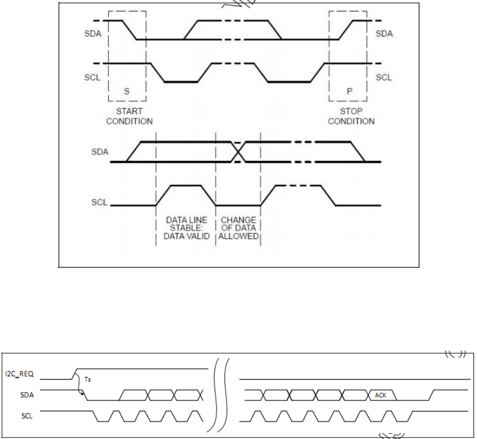
BSC Timing waveform
I
2
C _REQ is an output signal from the module to the host that it wishes to communicate.
The timing diagram as below shows I
2
C _REQ as active high.
The I
2
C _REQ signal stays high until after the first byte has been read by the host.
I
2
C _REQ timing waveform
6
2. Hardware Specification
2.1 Antenna Electrical Specification
Parameter Typical Units
Operating frequency range 13.56 MHz
Communication distance > 20 mm
3. Product Requirements
3.1 Hardware Requirements of NFC module
Form factor 15 mm x15mm module with 11-pin FPC connector
Host Interface BSC (I
2
C -compatible) interface
PCB 4-layer design
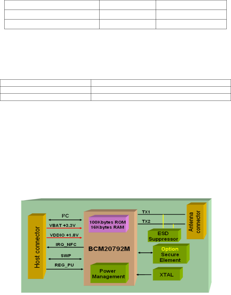
3.2 Hardware Architecture of NFC module
The T77H519 NFC module is based on Broadcom BCM20792M solution, which is
integrated NFC subsystem, interfaces, and microprocessor and memory unit. This module
is powered from the host (3.3V) and interfaces to the host with I
2
C signals and with one-
printed antennas, one on-board 26 MHz XTAL and one Secure Element (eSE) with
800kBytes flash memory (option).
The functional block diagram is shown as below.
7
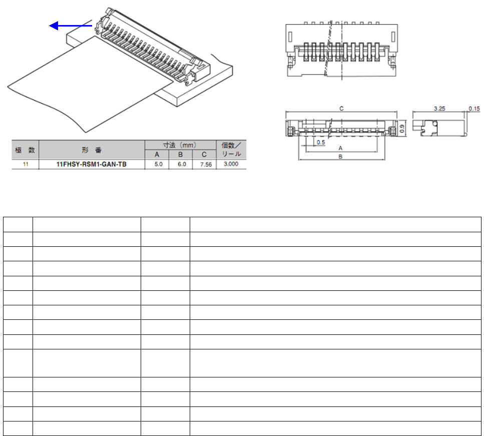
4. Interface of Connector of NFC module
Manufacturer: JST
Manufacturer Part number: 11FHSY-RSM1-GAN-TB(HF)
Pin definition
Pin
Symbol I/O Note
1 VBAT I Power supply from battery (2.8V - 5.5V)
2 VDDIO I Power supply to I/O (1.62V – 3.6V)
3 I
2
C -SDA I/O BSC Serial Data Line, active low
4 I
2
C -SCL I BSC Serial Clock
5 GND G Ground
6 IRQ-NFC O BSC request, active high (Host_Wake)
7 NFC_PRESENCE
G Ground
8 REG_UP I NFC Power-on
9 VDD_Ext_SE O Power supply to External Secure Element
(1.8V or 3.0V)
10
UIM_PWR I Power supply to UICC (1.78V – 3.3V)
11
SWP I/O SWP I/O 0 (Single-Wire Protocol interface)
S1
GND G Ground
S2
GND G Ground
Remark: The connector is bottom conduct with golden plating of FPC
cable
Pin 1
Pin 1
8
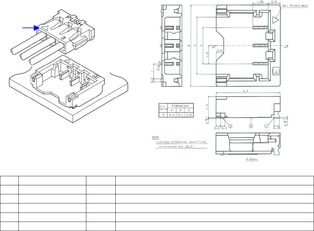
5. Antenna connector of NFC module
Manufacturer: JST
Manufacturer Part number: BM03B-ACHKS-GAN-TF(HF)
Pin definition
Pin
Symbol I/O Note
1 TX2 I/O Coil output 2
2 GND G Ground
3 TXI I/O Coil output 1
S1
GND G Ground
S2
GND G Ground
Top view
Pin 1
9
6. Test Operating Instructions Info
Please refer to another file named “Test SOP for T77H519 NFC series
projects”.

COMPANY CONFIDENTIAL
Industry Canada statement:
This device complies with RSS-210 of the Industry Canada Rules. Operation is subject to
the following two conditions: (1) This device may not cause harmful interference, and (2)
this device must accept any interference received, including interference that may cause
undesired operation.
Ce dispositif est conforme à la norme CNR-210 d'Industrie Canada applicable aux
appareils radio exempts de licence. Son fonctionnement est sujet aux deux conditions
suivantes: (1) le dispositif ne doit pas produire de brouillage préjudiciable, et (2) ce
dispositif doit accepter tout brouillage reçu, y compris un brouillage susceptible de
provoquer un fonctionnement indésirable.
Radiation Exposure Statement:
This equipment complies with IC radiation exposure limits set forth for an uncontrolled
environment. This equipment should be installed and operated with minimum distance
20cm between the radiator & your body.
Déclaration d'exposition aux radiations:
Cet équipement est conforme aux limites d'exposition aux rayonnements IC établies pour
un environnement non contrôlé. Cet équipement doit être installé et utilisé avec un
minimum de 20 cm de distance entre la source de rayonnement et votre corps.
This device is intended only for OEM integrators under the following conditions:
(For module device use)
1) The antenna must be installed such that 20 cm is maintained between the antenna and
users, and
2) The transmitter module may not be co-located with any other transmitter or antenna.
As long as 2 conditions above are met, further transmitter test will not be required.
However, the OEM integrator is still responsible for testing their end-product for any
additional compliance requirements required with this module installed.
Cet appareil est conçu uniquement pour les intégrateurs OEM dans les conditions
suivantes: (Pour utilisation de dispositif module)
1) L'antenne doit être installée de telle sorte qu'une distance de 20 cm est respectée entre
l'antenne et les utilisateurs, et
2) Le module émetteur peut ne pas être coïmplanté avec un autre émetteur ou antenne.
Tant que les 2 conditions ci-dessus sont remplies, des essais supplémentaires sur
l'émetteur ne seront pas nécessaires. Toutefois, l'intégrateur OEM est toujours
responsable des essais sur son produit final pour toutes exigences de conformité
supplémentaires requis pour ce module installé.

COMPANY CONFIDENTIAL
IMPORTANT NOTE:
In the event that these conditions can not be met (for example certain laptop configurations
or co-location with another transmitter), then the Canada authorization is no longer
considered valid and the IC ID can not be used on the final product. In these
circumstances, the OEM integrator will be responsible for re-evaluating the end product
(including the transmitter) and obtaining a separate Canada authorization.
NOTE IMPORTANTE:
Dans le cas où ces conditions ne peuvent être satisfaites (par exemple pour certaines
configurations d'ordinateur portable ou de certaines co-localisation avec un autre
émetteur), l'autorisation du Canada n'est plus considéré comme valide et l'ID IC ne peut
pas être utilisé sur le produit final. Dans ces circonstances, l'intégrateur OEM sera chargé
de réévaluer le produit final (y compris l'émetteur) et l'obtention d'une autorisation distincte
au Canada.
End Product Labeling
This transmitter module is authorized only for use in device where the antenna may be
installed such that 20 cm may be maintained between the antenna and users. The final
end product must be labeled in a visible area with the following: “Contains IC: 2878D-
T77H519”.
Plaque signalétique du produit final
Ce module émetteur est autorisé uniquement pour une utilisation dans un dispositif où
l'antenne peut être installée de telle sorte qu'une distance de 20cm peut être maintenue
entre l'antenne et les utilisateurs. Le produit final doit être étiqueté dans un endroit visible
avec l'inscription suivante: "Contient des IC: 2878D- T77H519".
Manual Information To the End User
The OEM integrator has to be aware not to provide information to the end user regarding
how to install or remove this RF module in the user’s manual of the end product which
integrates this module.
The end user manual shall include all required regulatory information/warning as show in
this manual.
Manuel d'information à l'utilisateur final
L'intégrateur OEM doit être conscient de ne pas fournir des informations à l'utilisateur final
quant à la façon d'installer ou de supprimer ce module RF dans le manuel de l'utilisateur
du produit final qui intègre ce module.
Le manuel de l'utilisateur final doit inclure toutes les informations réglementaires requises
et avertissements comme indiqué dans ce manuel.

COMPANY CONFIDENTIAL
Federal Communication Commission Interference Statement
This device complies with Part 15 of the FCC Rules. Operation is subject to the
following two conditions: (1) This device may not cause harmful interference, and
(2) this device must accept any interference received, including interference that
may cause undesired operation.
This equipment has been tested and found to comply with the limits for a Class B
digital device, pursuant to Part 15 of the FCC Rules. These limits are designed to
provide reasonable protection against harmful interference in a residential
installation. This equipment generates, uses and can radiate radio frequency energy
and, if not installed and used in accordance with the instructions, may cause
harmful interference to radio communications. However, there is no guarantee that
interference will not occur in a particular installation. If this equipment does cause
harmful interference to radio or television reception, which can be determined by
turning the equipment off and on, the user is encouraged to try to correct the
interference by one of the following measures:
- Reorient or relocate the receiving antenna.
- Increase the separation between the equipment and receiver.
- Connect the equipment into an outlet on a circuit different from that
to which the receiver is connected.
- Consult the dealer or an experienced radio/TV technician for help.
FCC Caution: Any changes or modifications not expressly approved by the party
responsible for compliance could void the user's authority to operate this equipment.
This transmitter must not be co-located or operating in conjunction with any other
antenna or transmitter.
Radiation Exposure Statement:
This equipment complies with FCC radiation exposure limits set forth for an
uncontrolled environment. This equipment should be installed and operated with
minimum distance 20cm between the radiator & your body.
This device is intended only for OEM integrators under the following conditions:
1) The antenna must be installed such that 20 cm is maintained between the antenna
and users, and
2) The transmitter module may not be co-located with any other transmitter or
antenna.
As long as 2 conditions above are met, further transmitter test will not be required.
However, the OEM integrator is still responsible for testing their end-product for any

COMPANY CONFIDENTIAL
additional compliance requirements required with this module installed
IMPORTANT NOTE: In the event that these conditions can not be met (for example
certain laptop configurations or co-location with another transmitter), then the FCC
authorization is no longer considered valid and the FCC ID can not be used on the
final product. In these circumstances, the OEM integrator will be responsible for
reevaluating
the end product (including the transmitter) and obtaining a separate FCC
authorization.
End Product Labeling
This transmitter module is authorized only for use in device where the antenna may be
installed such that 20 cm may be maintained between the antenna and users. The
final end product must be labeled in a visible area with the following: “Contains FCC
ID: MCLT77H519”. The grantee's FCC ID can be used only when all FCC compliance
requirements are met.
Manual Information To the End User
The OEM integrator has to be aware not to provide information to the end user
regarding how to install or remove this RF module in the user’s manual of the end
product which integrates this module.
The end user manual shall include all required regulatory information/warning as show
in this manual.
For Taiwan 警語:
經型式認證合格之低功率射頻電機,非經許可,公司、商號或使用者均不得擅自變更頻
率、加大功率或變更原設計之特性及功能。
低功率射頻電機之使用不得影響飛航安全及干擾合法通信;經發現有干擾現象時,應立
即停用,並改善至無干擾時方得繼續使用。前項合法通信,指依電信法規定作業之無線
電通信。低功率射頻電機須忍受合法通信或工業、科學及醫療用電波輻射性電機設備之
干擾。
Note: 1. 本模組於取得認證後將依規定於模組本體標示審驗合格標籤 2. 系統廠商應於平台上標示「本產品內
含射頻模組: XXXyyyLPDzzzz-x (NCC ID) 」字樣