HON HAI PRECISION IND T77H526 802.11ac+802.11abgn + BT4.0+BT3.0+BT2.1/EDR Module User Manual
HON HAI Precision Ind. Co., Ltd. 802.11ac+802.11abgn + BT4.0+BT3.0+BT2.1/EDR Module
User Manual.pdf
COMPANY CONFIDENTIAL
1
Project Name
IEEE802.11 ac/n/a/b/g
Bluetooth 4.0
NFC (Near Field Communication)
NGFF1216-S3 Card
Approval Sheet Rev.
0.2
FOXCONN Part No.
T77H526.01
Module Rev. 015
Customer Part No. TBD
Prepared by Reviewed by Approved by
Wei.Liao
Approval Sheet

COMPANY CONFIDENTIAL
2
Revision History
T77H526.01 is made in China,
Manufactured by HongFuJin Precision Industry Co., LTD
Manufacture Site: ShenZhen, Chongqing, Nanning
http://www.foxconn.com
Revision Date Originator Comment
0.1 2013/11/26
Wei.Liao Initial
0.2 2014/03/03
Wei.Liao
1> Add BAW Filter design as option
2> Add RF performance specification
3> Add package type

COMPANY CONFIDENTIAL
3
Content
REVISION HISTORY .......................................................................................................................................................2
1. INTRODUCTION ..........................................................................................................................................................4
2. MODULE HARDWARE OVERVIEW.........................................................................................................................5
3. ELECTRICAL CHARACTERISTICS .........................................................................................................................6
4. MECHANICAL DRAWING..........................................................................................................................................9
5. WLAN RF SPECIFICATION.....................................................................................................................................11
6. REFERENCE PERIPHERAL CIRCUIT..................................................................................................................23
7. SOFTWARE REQUIREMENT..................................................................................................................................26
8. PACKING SPECIFICATION .....................................................................................................................................27
9. ENVIRONMENTAL REQUIREMENTS ...................................................................................................................28
10. SOLDERING AND REFLOW CONDITION..........................................................................................................29

COMPANY CONFIDENTIAL
4
1. Introduction
The T77H526.01 NGFF1216-S3 Card is based on Marvell 88W8897-B0-CBK2-T solution
with WLAN/Bluetooth/NFC functions and provides DSSS and OFDM baseband modulation,
MAC, CPU, OTP (one time programmable) memory, host interfaces, power management
unit (PMU) and direct conversion WLAN RF radio.
1.1 Scope
IEEE 802.11 Standards
802.11 data rates of 1 and 2 Mbps
802.11b data rates of 5.5 and 11 Mbps
802.11a/g data rates of 6, 9, 12, 18, 24, 36, 48, and 54 Mbps
802.11n HT20 with 800ns GI data rates of 6.5, 13, 19.5, 26, 39, 52, 58.5 and 65Mbps
802.11n HT20 with 400ns GI data rates of 7.2,14.4, 21.7, 28.9, 43.3, 57.8, 65 and
72.2Mbps
802.11n HT40 with 800ns GI data rates of 13.5, 27, 40.5, 54, 81, 108, 121.5 and
135Mbps
802.11n HT40 with 400ns GI data rates of 15, 30, 45, 60, 90, 120, 135 and 150Mbps
802.11ac VHT80 with 800ns GI data rates of 29.3, 58.5, 87.8, 117, 175.5, 234, 263.3,
292.5, 351 and 390Mbps
802.11ac VHT80 with 400ns GI data rates of 32.5, 65, 97.5, 130, 195, 260, 292.5,
325, 390 and 433.3Mbps
802.11n up to 144.4Mbps (20 MHz), 300Mbps (40 MHz) for 2X2 MIMO.
802.11ac up to 173.3Mbps (20 MHz), 400Mbps (40 MHz), 866.7Mbps (80 MHz) for 2X2
MIMO.
Bluetooth
Bluetooth 4.0 + HS
Bluetooth Class 2
Bluetooth Class 1
Baseband and radio BDR and EDR packet types—1 Mbps (GFSK), 2 Mbps (π /4-
DQPSK), and 3 Mbps (8DPSK)
Supports Low Energy (LE)
NFC (Near field communication)
Full protocol support ISO 14443A/B, ISO 18092, ISO 15693,NFCIP-1, NFC Forum,
EMV contactless targets with data rates up to 848Kbps.
Support Reader/Writer, Card Emulation, and Peer-to-Peer (P2P) modes.
COMPANY CONFIDENTIAL
5
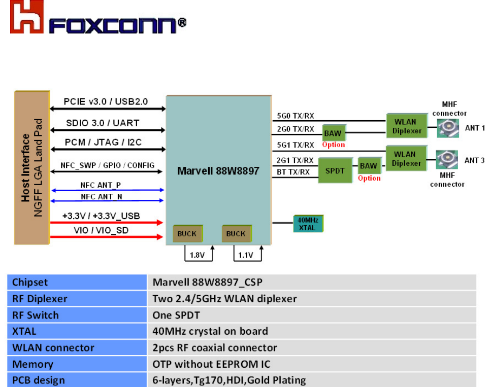
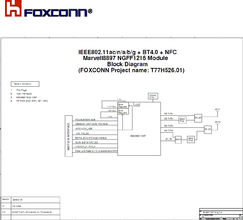
2. Module Hardware Overview
Block Diagram
Features
IEEE802.11a/b/g/n /ac (2X2 MIMO) + BT4.0 + NFC Module.
2.4GHz + 5GHz bands RF interface.
Host interface for WLAN, Bluetooth and NFC Configure from platform.
PCIE M.2 Type 1216-S3 card with 76 pins Soldered down solution Module.
+3.3V +/- 5% supply power from host platform for VBAT.
+1.8V +/- 5% supply power from host platform for digital IO SDIO.
Two RF micro-coaxial connectors (2.0mmx2.0mm), One for Wi-Fi1 antenna port,
Another antenna port shared by Wi-Fi2 and BT
Uses MRVL 88W8897 integrated OTP memory instead of external EEPROM.
Use LGA PAD connects for NFC external antenna.
Provide coexistence interface for connecting to an external LTE (Long Term Evolution)
device.
RoHS and Green Compliant.
Module
Configure from platform.
COMPANY CONFIDENTIAL
6
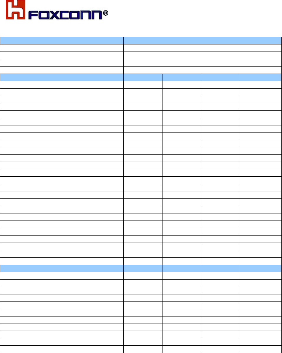
3. Electrical Characteristics
3.1 DC Characteristics (recommended operating rating)
Parameter Minimum Typical Maximum Units
+3.3V (Analog power supply) 2.97 3.3 3.63 V
+3.3V_USB (USB power supply) 2.97 3.3 3.63 V
2.97 3.3 3.63 V
+VIO (Digital I/O power supply) 1.62 1.8 1.98 V
VIO_SD (Digital I/O SDIO power
supply)
1.62 1.8 1.98 V
Storage Temperature -30 ~ +85 ℃
Storage Humidity 0 ~ 90 %
Operation Temperature 0 ~ 60 ℃
HBM - 1.0K - V
ESD Level MM - 200 - V
3.3 Host interface
Configure table
Configuration WLAN BT / NFC BTAMPS
CONFIG_HOST [3:0] = b1111 PCIE UART N/A
CONFIG_HOST [3:0] = b1110 PCIE USB USB
CONFIG_HOST [3:0] = b1101 SDIO UART SDIO
CONFIG_HOST [3:0] = b0111 SDIO SDIO SDIO
CONFIG_HOST [3:0] = b0110 USB USB USB
CONFIG_HOST [3:0] = b0010 USB UART USB
PCIe Interface
The 88W8897 PCI Express Interface Unit (PCIe) functions as a PCI Express endpoint
device that conforms to the following standards:
PCI Express Base Specification, Revision 3.0
PCI Express Card Electromechanical Specification, Revision 1.1
PCI Express Bus Power Management Interface Specification, Revision 1.2
PCI Express Mini Card Electromechanical Specification, Revision 1.2
Express Card Standard, Revision 1.1
Latency Tolerance Reporting (LTR) Capability
L1 Substates ECR Capability
BT

COMPANY CONFIDENTIAL
7
USB 2.0 Device Interface
The USB device interface is compliant with the Universal Serial Bus Specification,
Revision 2.0, April 27, 2000. A USB host uses the USB cable bus and the USB 2.0 device
Interface to communicate with the chip.
The main features of the USB device interface include:
High/full speed operation (480/12 Mbps)
Suspend/host resume/device resume (remote wake-up)
Built-in DMA engine that reduces interrupt loads on the embedded processor and
reduces the system bus bandwidth requirement for serving the USB device operation
Supports Link Power Management (LPM), corresponding host resume or device resume
(remote wakeup) to exit from L1 sleep state
The USB 2.0 device interface is designed with 3.3V signal level pads.
SDIO Device Interface
The 88W8897 supports a SDIO device interface that conforms to the industry standard
SDIO full-speed card specification and allows a host controller using the SDIO bus protocol
to access the wireless SoC device.
The SDIO device interface main features include:
Supports SDIO 3.0 standard
On chip memory used for CIS
Supports SPI, 1-bit SDIO, and 4-bit SDIO transfer modes at the full clock range of 0 to
208MHz
Special interrupt register for information exchange
Allows card to interrupt host
High-Speed UART Interface
The 88W8897 supports a high-speed Universal asynchronous receiver/transmitter interface,
compliant to the industry standard 16650 specification.
The UART interface features include:

COMPANY CONFIDENTIAL
8
FIFO mode permanently selected for transmit and receive operations
2 pins for transmit and receive operations
2 flow control pins
Interrupt triggers for low power, high throughput operation
3.4 Power up sequence
The following requirements must be met for correct power up:
Ramp-up time of +3.3V should be < 5ms.
PDn is tied to +3.3V directly.
External +3.3V/+VIO/+3.3V_USB
from host
VIO_SD is provided by host if SDIO interface is used.
GPIO_3 need tied to +VIO by host if SDIO interface is used.
COMPANY CONFIDENTIAL
9
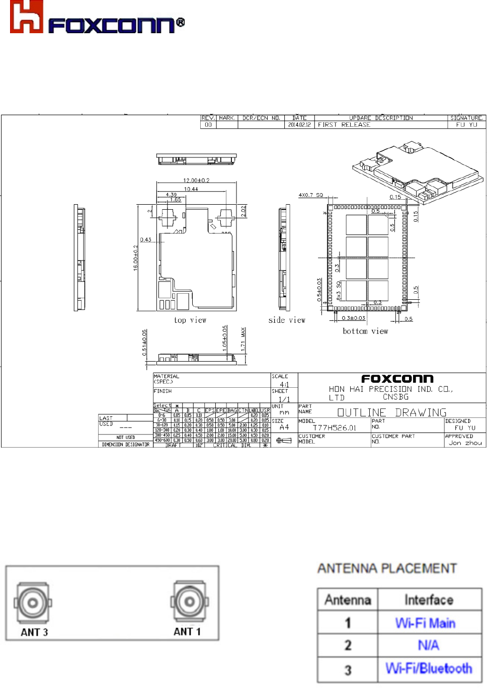
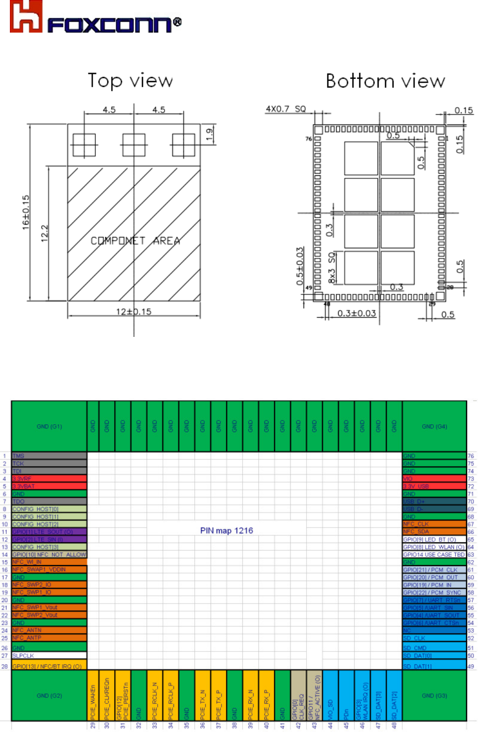
4. Mechanical Drawing
4.1 Module dimension
4.2 Antenna of Connector location
COMPANY CONFIDENTIAL
10
4.3 Card Pin-mapping
COMPANY CONFIDENTIAL
11
5. WLAN RF Specification
This specification is based on additional references listed below for each RF chain.
IEEE Std. 802.11ac
IEEE Std. 802.11a
IEEE Std. 802.11b
IEEE Std. 802.11g
IEEE Std. 802.11n
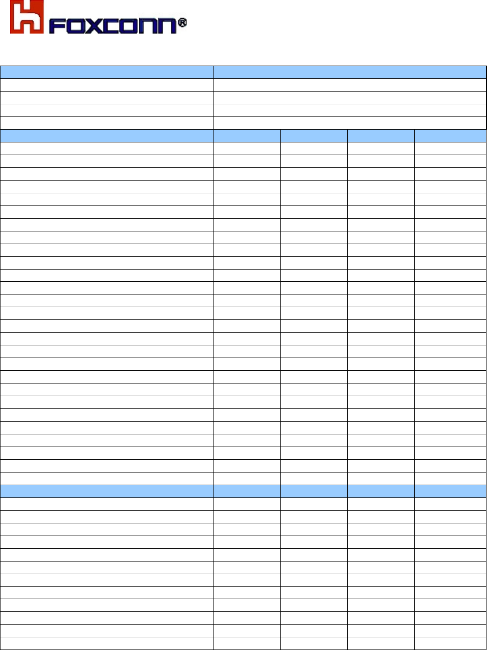
IEEE802.11b
Items Contents
Standard IEEE802.11b
Modulation DBPSK/DQPSK/CCK
Channel CH1 to CH13, CH14
Data rate 1, 2, 5.5, 11Mbps
TX Characteristics Min. Typ Max. Unit
1. Power Levels (Calibrated)
1) 1Mbps +14.5 +16 +17.5 dBm
2) 2Mbps
+14.5 +16 +17.5 dBm
3) 5.5Mbps
+14.5 +16 +17.5 dBm
4) 11Mbps
+14.5 +16 +17.5 dBm
2. Spectrum Mask
1) fc +/-11MHz to +/-22MHz - - -30 dBr
2) fc > +/-22MHz - - -50 dBr
3. Modulation Accuracy (EVM)
1) 1Mbps - -27 -9.10 dB
2) 2Mbps - -27 -9.10 dB
3) 5.5Mbps - -27 -9.10 dB
4) 11Mbps - -27 -9.10 dB
4. Frequency Error -25 - +25 ppm
RX Characteristics Min. Typ Max. Unit
5. Minimum Input Level Sensitivity
1) 1Mbps (FER 8%) - -95 -76 dBm
2) 2Mbps (FER 8%) -
-94
-76 dBm
3) 5.5Mbps (FER 8%) -
-91 -76 dBm
4) 11Mbps (FER 8%) -
-88 -76 dBm
6. Maximum Input Level (FER 8%) -10 - - dBm

COMPANY CONFIDENTIAL
12
IEEE802.11g
Items Contents
Standard IEEE802.11g
Modulation OFDM
Channel CH1 to CH13
Data rate 6, 9, 12, 18, 24, 36, 48, 54Mbps
TX Characteristics Min. Typ. Max. Unit
1. Power Levels (Calibrated)
1) 6Mbps
13.5 15 16.5 dBm
2) 9Mbps
13.5 15 16.5 dBm
3) 12Mbps
13.5 15 16.5 dBm
4) 18Mbps
13.5 15 16.5 dBm
5) 24Mbps
13.5 15 16.5 dBm
6) 36Mbps
13.5 15 16.5 dBm
7) 48Mbps
13.5 15 16.5 dBm
8) 54Mbps
13.5 15 16.5 dBm
2. Spectrum Mask
1) fc +/- 11MHz - - -20 dBr
2) fc +/- 20MHz - - -28 dBr
3) fc > +/-30MHz - - -40 dBr
3. Modulation Accuracy (EVM)
1) 6Mbps - -32 -5 dB
2) 9Mbps - -32 -8 dB
3) 12Mbps - -32 -10 dB
4) 18Mbps - -32 -13 dB
5) 24Mbps - -32 -16 dB
6) 36Mbps - -32 -19 dB
7) 48Mbps - -32 -22 dB
8) 54Mbps - -32 -25 dB
4. Frequency Error -25 - +25 ppm
RX Characteristics Min. Typ. Max. Unit
5. Minimum Input Level Sensitivity
1) 6Mbps (PER <10%) -89 -82 dBm
2) 9Mbps (PER < 10%) -88 -81 dBm
3) 12Mbps (PER < 10%) -87 -79 dBm
4) 18Mbps (PER < 10%) -86 -77 dBm
5) 24Mbps (PER < 10%) -82 -74 dBm
6) 36Mbps (PER < 10%) -80 -70 dBm
7) 48Mbps (PER < 10%) -75 -66 dBm
8) 54Mbps (PER < 10%) -74 -65 dBm
6. Maximum Input Level (PER < 10%) -20 - - dBm

COMPANY CONFIDENTIAL
13
IEEE802.11n HT20-2.4G
Items Contents
Standard IEEE802.11n HT20
Modulation OFDM
Channel CH1 to CH13
Data rate (MCS index) MCS0~7
TX Characteristics Min. Typ. Max. Unit
1. Power Levels (Calibrated)
1) MCS0
12.5 14 15.5 dBm
2) MCS1
12.5 14 15.5 dBm
3) MCS2
12.5 14 15.5 dBm
4) MCS3
12.5 14 15.5 dBm
5) MCS4
12.5 14 15.5 dBm
6) MCS5
12.5 14 15.5 dBm
7) MCS6
12.5 14 15.5 dBm
8) MCS7
12.5 14 15.5 dBm
2. Spectrum Mask
1) fc +/- 11MHz - - -20 dBr
2) fc +/- 20MHz - - -28 dBr
3) fc > +/-30MHz - - -45 dBr
3. Modulation Accuracy (EVM)
1) MCS0 - -32 -5 dB
2) MCS1 - -32 -10 dB
3) MCS2 - -32 -13 dB
4) MCS3 - -32 -16 dB
5) MCS4 - -32 -19 dB
6) MCS5 - -32 -22 dB
7) MCS6 - -32 -25 dB
8) MCS7 - -32 -27 dB
4. Frequency Error -25 - +25 ppm
RX Characteristics Min. Typ. Max. Unit
5. Minimum Input Level Sensitivity
1) MCS0 (PER < 10%) - -89 -82 dBm
2) MCS1 (PER < 10%) - -87 -79 dBm
3) MCS2 (PER < 10%) - -85 -77 dBm
4) MCS3 (PER < 10%) - -80 -74 dBm
5) MCS4 (PER < 10%) - -78 -70 dBm
6) MCS5 (PER < 10%) - -75 -66 dBm
7) MCS6 (PER < 10%) - -72 -65 dBm
8) MCS7 (PER < 10%) - -71 -64 dBm
6. Maximum Input Level (PER < 10%) -20 - - dBm
COMPANY CONFIDENTIAL
14
IEEE802.11n HT40-2.4G
Items
Contents
Standard IEEE802.11n HT40
Modulation OFDM
Channel CH3~CH9
Data rate (MCS index) MCS0~MCS7
TX Characteristics Min. Typ. Max. Unit
1. Power Levels (Calibrated)
1) MCS0 11.5 13 14.5 dBm
2) MCS1 11.5 13 14.5 dBm
3) MCS2 11.5 13 14.5 dBm
4) MCS3 11.5 13 14.5 dBm
5) MCS4 11.5 13 14.5 dBm
6) MCS5 11.5 13 14.5 dBm
7) MCS6 11.5 13 14.5 dBm
8) MCS7 11.5 13 14.5 dBm
2. Spectrum Mask
1) fc +/- 21MHz - - -20 dBr
2) fc +/- 40MHz - - -28 dBr
3) fc > +/-60MHz - - -45 dBr
3. Modulation Accuracy (EVM)
1) MCS0 - -30 -5 dB
2) MCS1 - -30 -10 dB
3) MCS2 - -30 -13 dB
4) MCS3 - -30 -16 dB
5) MCS4 - -30 -19 dB
6) MCS5 - -30 -22 dB
7) MCS6 - -30 -25 dB
8) MCS7 - -30 -27 dB
4. Frequency Error -25 - +25 ppm
RX Characteristics Min. Typ. Max. Unit
5. Minimum Input Level Sensitivity
1) MCS0 (PER < 10%) - -86 -79 dBm
2) MCS1 (PER < 10%) - -84 -76 dBm
3) MCS2 (PER < 10%) - -81 -74 dBm
4) MCS3 (PER < 10%) -18 -71 dBm
5) MCS4 (PER < 10%) - -75 -67 dBm
6) MCS5 (PER < 10%) - -72 -63 dBm
7) MCS6 (PER < 10%) - -70 -62 dBm
8) MCS7 (PER < 10%) - -69 -61 dBm
6. Maximum Input Level (PER < 10%) -20 -
-
dBm
COMPANY CONFIDENTIAL
15
IEEE802.11a
Items
Contents
Standard IEEE802.11a
Modulation OFDM
Channel CH36~CH48, CH52~CH64, CH100~CH165
Data rate 6, 9, 12, 18, 24, 36, 48, 54Mbps
TX Characteristics Min. Typ. Max. Unit
1. Power Levels (Calibrated)
1) 6Mbps
13.5 15 16.5 dBm
2) 9Mbps
13.5 15 16.5 dBm
3) 12Mbps
13.5 15 16.5 dBm
4) 18Mbps
13.5 15 16.5 dBm
5) 24Mbps
13.5 15 16.5 dBm
6) 36Mbps
13.5 15 16.5 dBm
7) 48Mbps
13.5 15 16.5 dBm
8) 54Mbps
13.5 15 16.5 dBm
2. Spectrum Mask
1) fc +/- 11MHz - - -20 dBr
2) fc +/- 20MHz - - -28 dBr
3) fc > +/-30MHz - - -40 dBr
3. Modulation Accuracy (EVM)
1) 6Mbps - -24 -5 dB
2) 9Mbps - -25 -8 dB
3) 12Mbps - -25 -10 dB
4) 18Mbps - -25 -13 dB
5) 24Mbps - -25 -16 dB
6) 36Mbps - -25 -19 dB
7) 48Mbps - -27 -22 dB
8) 54Mbps - -30 -25 dB
4. Frequency Error -20 - +20 ppm
RX Characteristics Min. Typ. Max. Unit
5. Minimum Input Level Sensitivity
1) 6Mbps (PER <10%) - -87 -82 dBm
2) 9Mbps (PER < 10%) - -86 -81 dBm
3) 12Mbps (PER < 10%) - -84 -79 dBm
4) 18Mbps (PER < 10%) - -82 -77 dBm
5) 24Mbps (PER < 10%) - -79 -74 dBm
6) 36Mbps (PER < 10%) - -74 -70 dBm
7) 48Mbps (PER < 10%) - -72 -66 dBm
8) 54Mbps (PER < 10%) - -71 -65 dBm
6. Maximum Input Level (PER < 10%) -30 - - dBm
COMPANY CONFIDENTIAL
16
IEEE802.11n HT20-5G
Items Contents
Standard IEEE802.11n HT20
Modulation OFDM
Channel CH36~CH48, CH52~CH64, CH100~CH165
Data rate (MCS index) MCS0~7
TX Characteristics Min. Typ. Max. Unit
1. Power Levels (Calibrated)
1) MCS0 12.5 14 15.5 dBm
2) MCS1 12.5 14 15.5 dBm
3) MCS2 12.5 14 15.5 dBm
4) MCS3 12.5 14 15.5 dBm
5) MCS4 12.5 14 15.5 dBm
6) MCS5 12.5 14 15.5 dBm
7) MCS6 12.5 14 15.5 dBm
8) MCS7 12.5 14 15.5 dBm
3. Spectrum Mask
1) fc +/- 11MHz - - -20 dBr
2) fc +/- 20MHz - - -28 dBr
3) fc > +/-30MHz - - -40 dBr
3. Modulation Accuracy (EVM)
1) MCS0 - -30 -5 dB
2) MCS1 - -30 -10 dB
3) MCS2 - -30 -13 dB
4) MCS3 - -30 -16 dB
5) MCS4 - -30 -19 dB
6) MCS5 - -30 -22 dB
7) MCS6 - -30 -25 dB
8) MCS7 - -30 -27 dB
4. Frequency Error -20 - +20 ppm
RX Characteristics Min. Typ. Max. Unit
5. Minimum Input Level Sensitivity
1) MCS0 (PER < 10%) - -86 -82 dBm
2) MCS1 (PER < 10%) - -84 -79 dBm
3) MCS2 (PER < 10%) - -81 -77 dBm
4) MCS3 (PER < 10%) - -78 -74 dBm
5) MCS4 (PER < 10%) - -74 -70 dBm
6) MCS5 (PER < 10%) - -70 -66 dBm
7) MCS6 (PER < 10%) - -69 -65 dBm
8) MCS7 (PER < 10%) - -68 -64 dBm
6. Maximum Input Level (PER < 10%) -30 - - dBm
COMPANY CONFIDENTIAL
17
IEEE802.11n HT40-5G
Items Contents
Standard IEEE802.11n HT40
Modulation OFDM
Channel CH38~CH62, CH102~CH159
Data rate (MCS index) MCS0~MCS7
TX Characteristics Min. Typ. Max. Unit
1. Power Levels (Calibrated)
1) MCS0 11.5 13 14.5 dBm
2) MCS1 11.5 13 14.5 dBm
3) MCS2 11.5 13 14.5 dBm
4) MCS3 11.5 13 14.5 dBm
5) MCS4 11.5 13 14.5 dBm
6) MCS5 11.5 13 14.5 dBm
7) MCS6 11.5 13 14.5 dBm
8) MCS7 11.5 13 14.5 dBm
2. Spectrum Mask
1) +/- 21MHz - - -20 dBr
2) +/- 40MHz - - -28 dBr
3) > +/-60MHz - - -40 dBr
3. Modulation Accuracy (EVM)
1) MCS0 - -30 -5 dB
2) MCS1 - -30 -10 dB
3) MCS2 - -30 -13 dB
4) MCS3 - -30 -16 dB
5) MCS4 - -30 -19 dB
6) MCS5 - -30 -22 dB
7) MCS6 - -30 -25 dB
8) MCS7 - -30 -27 dB
4. Frequency Error -20 - +20 ppm
RX Characteristics Min. Typ. Max. Unit
5. Minimum Input Level Sensitivity
1) MCS0 (PER < 10%) - -84 -79 dBm
2) MCS1 (PER < 10%) - -81 -76 dBm
3) MCS2 (PER < 10%) - -79 -74 dBm
4) MCS3 (PER < 10%) - -76 -71 dBm
5) MCS4 (PER < 10%) - -72 -67 dBm
6) MCS5 (PER < 10%) - -67 -63 dBm
7) MCS6 (PER < 10%) - -66 -62 dBm
8) MCS7 (PER < 10%) - -65 -61 dBm
6. Maximum Input Level (PER < 10%) -30 - - dBm
COMPANY CONFIDENTIAL
18
IEEE802.11ac VHT20
Items Contents
Standard IEEE802.11ac VHT20
Modulation OFDM
Channel CH36~CH48, CH52~CH64, CH100~CH165
Data rate (MCS index) MCS0~MCS8
TX Characteristics Min. Typ. Max. Unit
1. Power Levels (Calibrated)
1) MCS0 6.5 8 9.5 dBm
2) MCS1 6.5 8 9.5 dBm
3) MCS2
6.5 8 9.5 dBm
4) MCS3
6.5 8 9.5 dBm
5) MCS4
6.5 8 9.5 dBm
6) MCS5
6.5 8 9.5 dBm
7) MCS6
6.5 8 9.5 dBm
8) MCS7
6.5 8 9.5 dBm
9) MCS8
6.5 8 9.5 dBm
2. Spectrum Mask
1) fc +/-11MHz - - -20 dBr
2) fc +/-20MHz - - -28 dBr
3) fc > +/-30MHz - - -40 dBr
3. Modulation Accuracy (EVM)
1) MCS0 - -33 -5 dB
2) MCS1 - -33 -10 dB
3) MCS2 - -33 -13 dB
4) MCS3 - -33 -16 dB
5) MCS4 - -33 -19 dB
6) MCS5 - -33 -22 dB
7) MCS6 - -33 -25 dB
8) MCS7 - -33 -27 dB
9) MCS8 - -33 -30 dB
4. Frequency Error -20 - +20 ppm
RX Characteristics Min. Typ. Max. Unit
5. Minimum Input Level Sensitivity
1) MCS0 (PER < 10%) - -89 -82 dBm
2) MCS1 (PER < 10%) - -85 -79 dBm
3) MCS2 (PER < 10%) - -83 -77 dBm
4) MCS3 (PER < 10%) - -80 -74 dBm
5) MCS4 (PER < 10%) - -75 -70 dBm
6) MCS5 (PER < 10%) - -72 -66 dBm
7) MCS6 (PER < 10%) - -71 -65 dBm
8) MCS7 (PER < 10%) - -70 -64 dBm
9) MCS8 (PER < 10%) - -66 -59 dBm
6. Maximum Input Level (PER < 10%) -30 - - dBm
COMPANY CONFIDENTIAL
19
IEEE802.11ac VHT40
Items Contents
Standard IEEE802.11ac VHT40
Modulation OFDM
Channel CH38~CH62, CH102~CH159
Data rate (MCS index) MCS0~MCS9
TX Characteristics Min. Typ. Max. Unit
1. Power Levels (Calibrated)
1) MCS0 6.5 8 9.5 dBm
2) MCS1 6.5 8 9.5 dBm
3) MCS2 6.5 8 9.5 dBm
4) MCS3 6.5 8 9.5 dBm
5) MCS4 6.5 8 9.5 dBm
6) MCS5 6.5 8 9.5 dBm
7) MCS6 6.5 8 9.5 dBm
8) MCS7 6.5 8 9.5 dBm
9) MCS8 6.5 8 9.5 dBm
10) MCS9 6.5 8 9.5 dBm
2. Spectrum Mask
1) fc +/-21MHz - -30 -20 dBr
2) fc +/-40MHz - -37 -28 dBr
3) fc > +/-60MHz - -50 -40 dBr
3. Modulation Accuracy (EVM)
1) MCS0 - -33 -5 dB
2) MCS1 - -33 -10 dB
3) MCS2 - -33 -13 dB
4) MCS3 - -33 -16 dB
5) MCS4 - -33 -19 dB
6) MCS5 - -33 -22 dB
7) MCS6 - -33 -25 dB
8) MCS7 - -33 -27 dB
9) MCS8 - -33 -30 dB
10) MCS9 - -33 -32 dB
4. Frequency Error -20 - +20 ppm
RX Characteristics Min. Typ. Max. Unit
5. Minimum Input Level Sensitivity
1) MCS0 (PER < 10%) - -86 -79 dBm
2) MCS1 (PER < 10%) - -83 -76 dBm
3) MCS2 (PER < 10%) - -81 -74 dBm
4) MCS3 (PER < 10%) - -77 -71 dBm
5) MCS4 (PER < 10%) - -73 -67 dBm
6) MCS5 (PER < 10%) - -70 -63 dBm
7) MCS6 (PER < 10%) - -69 -62 dBm
8) MCS7 (PER < 10%) - -66 -61 dBm
9) MCS8 (PER < 10%) - -64 -56 dBm
10) MCS9 (PER < 10%) - -62 -54 dBm
6. Maximum Input Level (PER < 10%) -30 - - dBm
COMPANY CONFIDENTIAL
20
IEEE802.11ac VHT80
Items Contents
Standard IEEE802.11ac VHT80
Modulation OFDM
Channel CH42,CH58,CH106,CH122,CH138,CH155
Data rate (MCS index) MCS0~MCS9
TX Characteristics Min. Typ. Max. Unit
1. Power Levels (Calibrated)
1) MCS0 6.5 8 9.5 dBm
2) MCS1 6.5 8 9.5 dBm
3) MCS2 6.5 8 9.5 dBm
4) MCS3 6.5 8 9.5 dBm
5) MCS4 6.5 8 9.5 dBm
6) MCS5 6.5 8 9.5 dBm
7) MCS6 6.5 8 9.5 dBm
8) MCS7 6.5 8 9.5 dBm
9) MCS8 6.5 8 9.5 dBm
10) MCS9 6.5 8 9.5 dBm
2. Spectrum Mask
1) +/-41MHz - -25 -20 dBr
2) +/-80MHz - -33 -28 dBr
3) +/-120MHz - -45 -40 dBr
3. Modulation Accuracy (EVM)
1) MCS0 - -33 -5 dB
2) MCS1 - -33 -10 dB
3) MCS2 - -33 -13 dB
4) MCS3 - -33 -16 dB
5) MCS4 - -33 -19 dB
6) MCS5 - -33 -22 dB
7) MCS6 - -33 -25 dB
8) MCS7 - -33 -27 dB
9) MCS8 - -33 -30 dB
10) MCS9 - -33 -32 dB
4. Frequency Error -20 - +20 ppm
RX Characteristics Min. Typ. Max. Unit
5. Minimum Input Level Sensitivity
1) MCS0 (PER < 10%) - -82 -76 dBm
2) MCS1 (PER < 10%) - -79 -73 dBm
3) MCS2 (PER < 10%) - -77 -71 dBm
4) MCS3 (PER < 10%) - -74 -68 dBm
5) MCS4 (PER < 10%) - -70 -64 dBm
6) MCS5 (PER < 10%) - -66 -60 dBm
7) MCS6 (PER < 10%) - -65 -59 dBm
8) MCS7 (PER < 10%) - -64 -58 dBm
9) MCS8 (PER < 10%) - -59 -53 dBm
10) MCS9 (PER < 10%) - -57 -51 dBm
6. Maximum Input Level (PER < 10%) -30 - - dBm
COMPANY CONFIDENTIAL
21
Bluetooth 4.0
Items Contents
Standard Bluetooth 4.0
Basic rate (BR),
Enhanced data rate (EDR).
Bluetooth low energy (BLE).
Modulation 1Mbps(GFSK),
2Mbps( /4-DQPSK),
3Mbps(8-DPSK)
Channel 2.402GHz ~ 2.480GHz (CH0~CH78)
Channel spacing 1 MHz for BR,EDR, 2MHz for LE
Duplex transmission Time-Division Duplex (TDD) scheme
TX Characteristics - BR Min. Typ. Max. Unit
1. Power Levels
1Mbps (GFSK) 5 7 9 dBm
2. Frequency Tolerance
Initial center frequency -75 3.2 75 kHz
3. Carrier Frequency Drift
Maximum drift rate within 50us -20 -4.5 20 kHz/50us
DH1 (Maximum length 1-slot packet) -25 -3 25 kHz
DH3 (Maximum length 3-slot packet) -40 0 40 kHz
DH5 (Maximum length 5-slot packet) -40 0 40 kHz
4. Modulation Characteristic (Frequency deviations)
f1avg 140
164 175 kHz
f2max 115 140 - kHz
f2avg/ f1avg/ Ratio 0.80
0.89 -
TX Characteristics - EDR Min.
Typ. Max. Unit
1. Power Levels
2Mbps( /4-DQPSK) 5 7 9 dBm
3Mbps(8-DPSK) 5 7 9 dBm
2.Carrier Frequency Stability and Modulation Accuracy
2Mbps: /4-DQPSK
Packet Initial Frequency Error: ωi -75 1.1 75 kHz
Block Frequency Error: ω0 -10 2.9 10 kHz
Total Frequency Error: ωi + ω0 -75 4 75 kHz
RMS DEVM - 0.05 0.2
Peak DEVM - 0.15 0.35
99% DEVM (% Symbols <=0.3) 99%
100% -
3Mbps: 8-DPSK
Initial Frequency Error: ωi -75 1.4 75 kHz
Frequency Error: ω0 -10 2.8 10 kHz
Block Frequency Error: ωi + ω0 -75 4.2 75 kHz
RMS DEVM - 0.05 0.13
Peak DEVM - 1.15 0.25
99% DEVM (% Symbols <=0.13) 99%
100% -
3. Differential Phase Encoding
2Mbps( /4-DQPSK) 99%
100% -
3Mbps(8-DPSK) 99%
100% -
TX Characteristics - BLE Min.
Typ. Max. Unit
1. Power Levels
1Mbps(GFSK) -2 0 +2 dBm
2. Modulation Characteristic (Frequency deviations)
f1avg 225
253 275 kHz
f2max 185
227 - kHz
f2avg/∆f1avg Ratio 0.8 0.92 -
3. Carrier frequency offset and drift
fn – fTX, n = 0, 1, 2, 3...k -150
2.57 +150 kHz
|f0 – fn|, n = 2, 3, 4...k - 1.41 50 kHz
COMPANY CONFIDENTIAL
22
|f1 – f0| - 0.98 20 kHz
|fn – fn-5|, n = 6, 7, 8...k - 0.49 20 kHz
RX Characteristics Min. Typ. Max. Unit
1. Minimum Input Level Sensitivity
GFSK (1Mbps) (BER 0.1%) - -88 -70 dBm
/4 DQPSK (2Mbps) (BER 0.1%) - -88 -70 dBm
8DPSK (3Mbps) (BER 0.1%) - -84 -70 dBm
GFSK (1Mbps) – BLE (BER< 30.8%) - -80 -70 dBm
2. Maximum Input Level
GFSK (1Mbps) (BER 0.1%) -20 - - dBm
/4 DQPSK (2Mbps) (BER 0.1%) -20 - - dBm
8DPSK (3Mbps) (BER 0.1%) -20 - - dBm
GFSK (1Mbps) – BLE (BER< 30.8%) -20 - - dBm
COMPANY CONFIDENTIAL
23
6. Schematics design
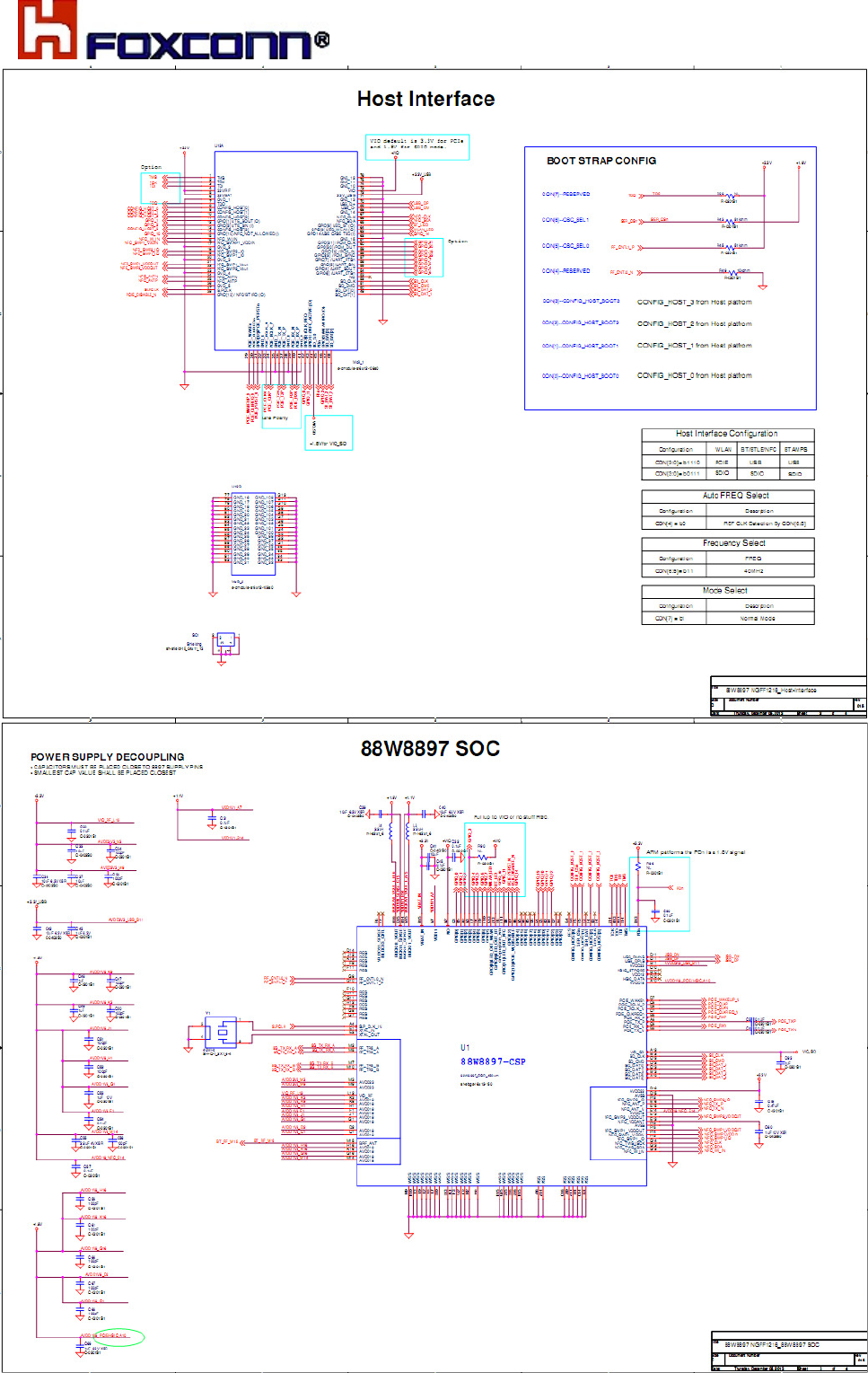
COMPANY CONFIDENTIAL
24
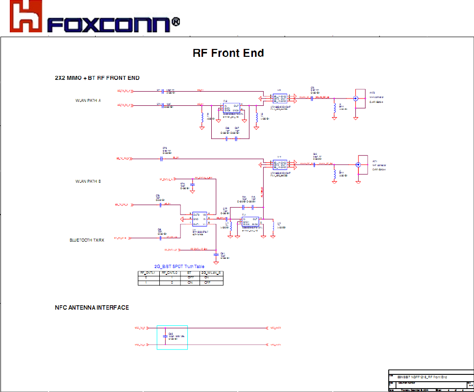
COMPANY CONFIDENTIAL
25

COMPANY CONFIDENTIAL
26
7. Software Requirement
Marvell is the owner for driver and Firmware release.
COMPANY CONFIDENTIAL
27
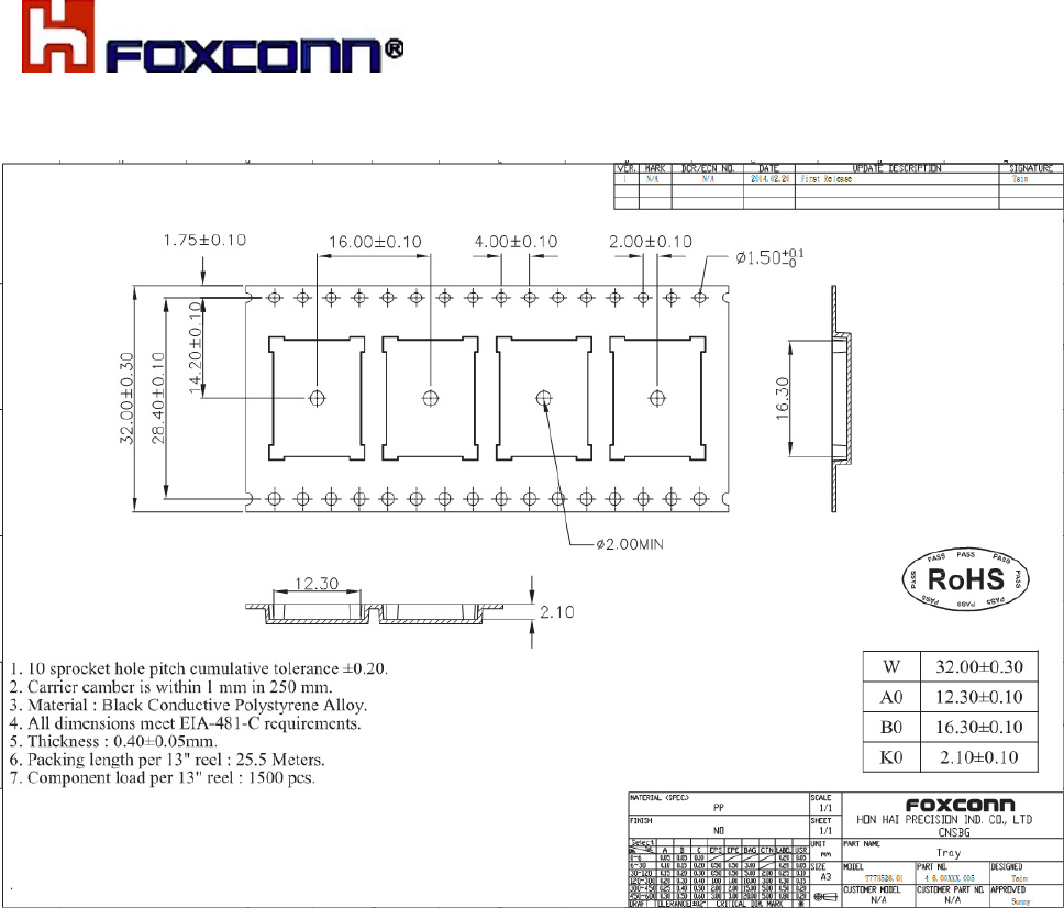
8. Packing Specification

COMPANY CONFIDENTIAL
28
9. Environmental Requirements
1> Operating Temperature Conditions
The product shall be capable of continuous reliable operation when operating in ambient
temperature of 0°C to 60°C.
2> Non-Operating Temperature Conditions
Neither subassemblies shall be damaged nor shall the operational performance be
degraded when restored to the operating temperature when exposed to storage
temperature in the range of -20°C to +85°C.
3> Operating Humidity Conditions
The product shall be capable of continuous reliable operation when subjected to relative
humidity in the range of 0% and 90% non-condensing.
4> Non-Operating Humidity conditions
The product shall not be damaged nor shall the performance be degraded after exposure
to relative humidity.
5> Terminals
The product is mounted with motherboard through Land Grid Array. In order to prevent
poor soldering, Please do not touch LGA portion by hand.
6> Falling
It will cause damage on the mounted components when the product is falling or receiving
drop shock. It may cause the product mal-function.
COMPANY CONFIDENTIAL
29
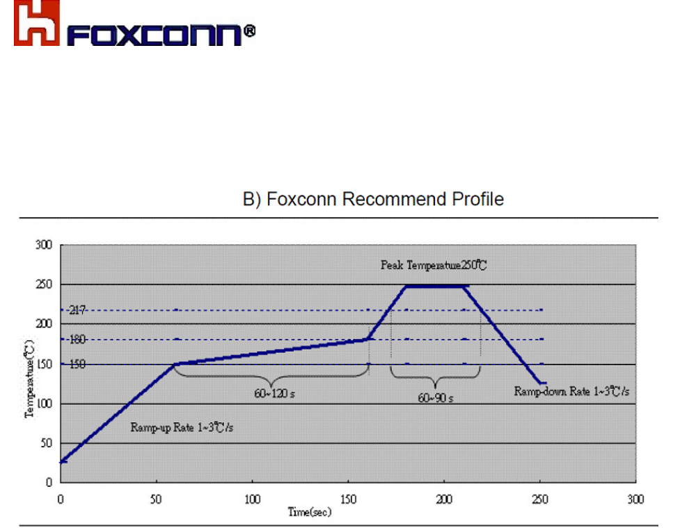
10. Soldering and reflow condition
Reflow soldering shall be done according to the below temperature profile.

COMPANY CONFIDENTIAL
39
10 Package information
TBD
Federal Communication Commission Interference Statement
This device complies with Part 15 of the FCC Rules. Operation is subject to the following two conditions: (1) This device
may not cause harmful interference, and (2) this device must accept any interference received, including interference
that may cause undesired operation.
This equipment has been tested and found to comply with the limits for a Class B digital device, pursuant to Part 15 of
the FCC Rules. These limits are designed to provide reasonable protection against harmful interference in a residential
installation. This equipment generates, uses and can radiate radio frequency energy and, if not installed and used in
accordance with the instructions, may cause harmful interference to radio communications. However, there is no
guarantee that interference will not occur in a particular installation. If this equipment does cause harmful interference to
radio or television reception, which can be determined by turning the equipment off and on, the user is encouraged to try
to correct the interference by one of the following measures:
- Reorient or relocate the receiving antenna.
- Increase the separation between the equipment and receiver.
- Connect the equipment into an outlet on a circuit different from that
to which the receiver is connected.
- Consult the dealer or an experienced radio/TV technician for help.
FCC Caution: Any changes or modifications not expressly approved by the party responsible for compliance could void
the user's authority to operate this equipment.
This transmitter must not be co-located or operating in conjunction with any other antenna or transmitter.
Radiation Exposure Statement:
This equipment complies with FCC radiation exposure limits set forth for an uncontrolled environment. This equipment
should be installed and operated with minimum distance 20cm between the radiator & your body.
This device is intended only for OEM integrators under the following conditions:
1) The antenna must be installed such that 20 cm is maintained between the antenna and users, and
2) The transmitter module may not be co-located with any other transmitter or antenna.
As long as 2 conditions above are met, further transmitter test will not be required. However, the OEM integrator is still
responsible for testing their end-product for any additional compliance requirements required with this module installed
IMPORTANT NOTE: In the event that these conditions can not be met (for example certain laptop configurations or co-
location with another transmitter), then the FCC authorization is no longer considered valid and the FCC ID can not be
used on the final product. In these circumstances, the OEM integrator will be responsible for re-evaluating the end
product (including the transmitter) and obtaining a separate FCC authorization.
End Product Labeling
This transmitter module is authorized only for use in device where the antenna may be installed such that 20 cm may be
maintained between the antenna and users. The final end product must be labeled in a visible area with the following:
“Contains FCC ID: MCLT77H526”. The grantee's FCC ID can be used only when all FCC compliance requirements are
met.
Manual Information To the End User
The OEM integrator has to be aware not to provide information to the end user regarding how to install or remove this
RF module in the user's manual of the end product which integrates this module.
The end user manual shall include all required regulatory information/warning as show in this manual.

39
Industry Canada statement:
This device complies with RSS-210 of the Industry Canada Rules. Operation is subject to the following
two conditions: (1) This device may not cause harmful interference, and (2) this device must accept any
interference received, including interference that may cause undesired operation.
Ce dispositif est conforme à la norme CNR-210 d'Industrie Canada applicable aux appareils radio
exempts de licence. Son fonctionnement est sujet aux deux conditions suivantes: (1) le dispositif ne
doit pas produire de brouillage préjudiciable, et (2) ce dispositif doit accepter tout brouillage reçu, y
compris un brouillage susceptible de provoquer un fonctionnement indésirable.
Radiation Exposure Statement:
This equipment complies with IC radiation exposure limits set forth for an uncontrolled environment.
This equipment should be installed and operated with minimum distance 20cm between the radiator &
your body.
Déclaration d'exposition aux radiations:
Cet équipement est conforme aux limites d'exposition aux rayonnements IC établies pour un
environnement non contrôlé. Cet équipement doit être installé et utilisé avec un minimum de 20 cm de
distance entre la source de rayonnement et votre corps.
This device is intended only for OEM integrators under the following conditions: (For module
device use)
1) The antenna must be installed such that 20 cm is maintained between the antenna and users, and
2) The transmitter module may not be co-located with any other transmitter or antenna.
As long as 2 conditions above are met, further transmitter test will not be required. However, the OEM
integrator is still responsible for testing their end-product for any additional compliance requirements
required with this module installed.
Cet appareil est conçu uniquement pour les intégrateurs OEM dans les conditions suivantes:
(Pour utilisation de dispositif module)
1) L'antenne doit être installée de telle sorte qu'une distance de 20 cm est respectée entre l'antenne et
les utilisateurs, et
2) Le module émetteur peut ne pas être coïmplanté avec un autre émetteur ou antenne.
Tant que les 2 conditions ci-dessus sont remplies, des essais supplémentaires sur l'émetteur ne seront
pas nécessaires. Toutefois, l'intégrateur OEM est toujours responsable des essais sur son produit final
pour toutes exigences de conformité supplémentaires requis pour ce module installé.
IMPORTANT NOTE:
In the event that these conditions can not be met (for example certain laptop configurations or
co-location with another transmitter), then the Canada authorization is no longer considered
valid and the IC ID can not be used on the final product. In these circumstances, the OEM
integrator will be responsible for re-evaluating the end product (including the transmitter) and
obtaining a separate Canada authorization.
NOTE IMPORTANTE:
Dans le cas où ces conditions ne peuvent être satisfaites (par exemple pour certaines
configurations d'ordinateur portable ou de certaines co-localisation avec un autre émetteur),
l'autorisation du Canada n'est plus considéré comme valide et l'ID IC ne peut pas être utilisé
sur le produit final. Dans ces circonstances, l'intégrateur OEM sera chargé de réévaluer le
produit final (y compris l'émetteur) et l'obtention d'une autorisation distincte au Canada.
End Product Labeling
This transmitter module is authorized only for use in device where the antenna may be
installed such that 20 cm may be maintained between the antenna and users. The final end
product must be labeled in a visible area with the following: “Contains IC: 2878D-T77H506”.
Plaque signalétique du produit final
Ce module émetteur est autorisé uniquement pour une utilisation dans un dispositif où
l'antenne peut être installée de telle sorte qu'une distance de 20cm peut être maintenue entre
l'antenne et les utilisateurs. Le produit final doit être étiqueté dans un endroit visible avec
l'inscription suivante: "Contient des IC: 2878D-T77H506".
Manual Information To the End User
The OEM integrator has to be aware not to provide information to the end user regarding how
to install or remove this RF module in the user’s manual of the end product which integrates
this module.
The end user manual shall include all required regulatory information/warning as show in this
2878D-T77H526
2878D-T77H526

40
manual.
Manuel d'information à l'utilisateur final
L'intégrateur OEM doit être conscient de ne pas fournir des informations à l'utilisateur final
quant à la façon d'installer ou de supprimer ce module RF dans le manuel de l'utilisateur du
produit final qui intègre ce module.
Le manuel de l'utilisateur final doit inclure toutes les informations réglementaires requises et
avertissements comme indiqué dans ce manuel.
Caution :
(i) the device for operation in the band 5150-5250 MHz is only for indoor use to reduce the
potential for harmful interference to co-channel mobile satellite systems;
(ii) the maximum antenna gain permitted for devices in the bands 5250-5350 MHz and
5470-5725 MHz shall comply with the e.i.r.p. limit; and
(iii) the maximum antenna gain permitted for devices in the band 5725-5825 MHz shall comply
with the e.i.r.p. limits specified for point-to-point and non point-to-point operation as
appropriate.
(iv) Users should also be advised that high-power radars are allocated as primary users (i.e.
priority users) of the bands 5250-5350 MHz and 5650-5850 MHz and that these radars could
cause interference and/or damage to LE-LAN devices.
Avertissement:
Le guide d’utilisation des dispositifs pour réseaux locaux doit inclure des instructions précises
sur les restrictions susmentionnées, notamment :
(i) les dispositifs fonctionnant dans la bande 5 150-5 250 MHz sont réservés uniquement pour
une utilisation à l’intérieur afin de réduire les risques de brouillage préjudiciable aux systèmes
de satellites mobiles utilisant les mêmes canaux;
(ii) le gain maximal d’antenne permis pour les dispositifs utilisant les bandes 5 250-5 350 MHz
et 5 470-5 725 MHz doit se conformer à la limite de p.i.r.e.;
(iii) le gain maximal d’antenne permis (pour les dispositifs utilisant la bande 5 725-5 825 MHz)
doit se conformer à la limite de p.i.r.e. spécifiée pour l’exploitation point à point et non point à
point, selon le cas.
(iv) De plus, les utilisateurs devraient aussi être avisés que les utilisateurs de radars de haute
puissance sont désignés utilisateurs principaux (c.-à-d., qu’ils ont la priorité) pour les bandes 5
250-5 350 MHz et 5 650-5 850 MHz et que ces radars pourraient causer du brouillage et/ou
des dommages aux dispositifs LAN-EL.
DETACHABLE ANTENNA USAGE
This device has been designed to operate with an antenna having a maximum gain of [-0.6]
dB. Antenna having a higher gain is strictly prohibited per regulations of Industry Canada. The
required antenna impedance is 50 ohms.
Under Industry Canada regulations, this radio transmitter may only operate using an antenna
of a type and maximum (or lesser) gain approved for the transmitter by Industry Canada. To
reduce potential radio interference to other users, the antenna type and its gain should be so
chosen that the equivalent isotropically radiated power (e.i.r.p.) is not more than that necessary
for successful communication.
This radio transmitter (IC: 2878D-T77H506 / Model: T77H506) has been approved by Industry
Canada to operate with the antenna types listed below with the maximum permissible gain and
required antenna impedance for each antenna type indicated. Antenna types not included in
this list, having a gain greater than the maximum gain indicated for that type, are strictly
prohibited for use with this device.
Ce dispositif a été conçu pour fonctionner avec une antenne ayant un gain maximal de dB
[-0.6]. Une antenne à gain plus élevé est strictement interdite par les règlements d'Industrie
Canada. L'impédance d'antenne requise est de 50 ohms.
2878D-T77H526
T77H526
1.84dBi.
1.84.

41
Conformément à la réglementation d'Industrie Canada, le présent émetteur radio
peutfonctionner avec une antenne d'un type et d'un gain maximal (ou inférieur) approuvé
pourl'émetteur par Industrie Canada. Dans le but de réduire les risques de brouillage
radioélectriqueà l'intention des autres utilisateurs, il faut choisir le type d'antenne et son gain
de sorte que lapuissance isotrope rayonnée équivalente (p.i.r.e.) ne dépasse pas l'intensité
nécessaire àl'établissement d'une communication satisfaisante.
Le présent émetteur radio (IC: 2878D-T77H506 / Modèle: T77H506) a été approuvé par
Industrie Canada pour fonctionner avec les types d'antenne énumérés ci-dessous et ayant un
gain admissible maximal et l'impédance requise pour chaque type d'antenne. Les types
d'antenne non inclus dans cette liste, ou dont le gain est supérieur au gain maximal indiqué,
sont strictement interdits pour l'exploitation de l'émetteur.
For Taiwan:低功率電波輻射性電機管理辦法
第十二條 經型式認證合格之低功率射頻電機,非經許可,公司、商號或使用者均不得擅自變更頻率、加大功率或變更原設
計之特性及功能。
第十四條 低功率射頻電機之使用不得影響飛航安全及干擾合法通信;經發現有干擾現象時,應立即停用,並改善至無干擾
時方得繼續使用。
前項合法通信,指依電信法規定作業之無線電通信。
低功率射頻電機須忍受合法通信或工業、科學及醫療用電波輻射性電機設備之干擾。
在5.25-5.35秭赫頻帶內操作之無線資訊傳輸設備,限於室內使用。
1. 本模組於取得認證後將依規定於模組本體標示審驗合格標籤。
2. 系統廠商應於平台上標示「本產品內含射頻模組: XXXyyyLPDzzzz-x」字樣。
T77H526
2878D-T77H526