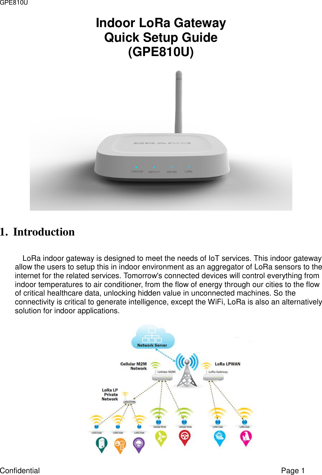
HON HAI PRECISION IND GPE810U LoRa Express Gateway User Manual Engineering Requirement Specification
HON HAI Precision Ind. Co., Ltd. LoRa Express Gateway Engineering Requirement Specification
UserManual.wiki
>
HON HAI PRECISION IND
>
GPE810U User Manual
Users Manual
Navigation menu
Upload a User Manual
Namespaces
Wiki Guide
HTML
PDF
Info
Views
User Manual
Discussion / Help
Navigation
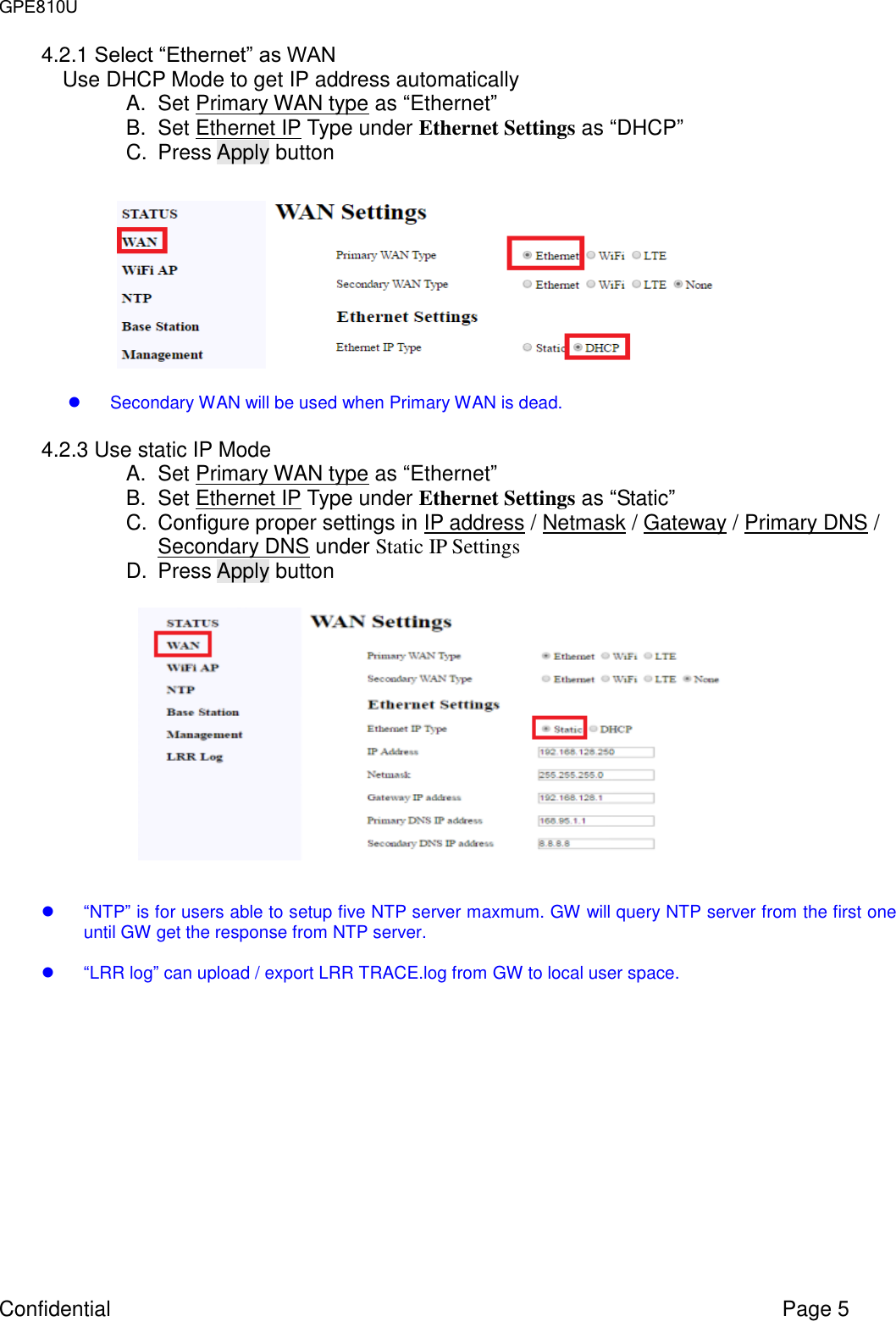
![GPE810U Confidential Page 4 4.2. Set WAN interface Select [WAN] page for setting WAN configuration WiFi client can be WAN interface, and it is independent from WiFi AP mode.](https://usermanual.wiki/HON-HAI-PRECISION-IND/GPE810U/User-Guide-3393820-Page-4.png)