HON HAI PRECISION IND J07M067 IBM Intergrated Bluetooth IV with 56K Modem User Manual manual new
HON HAI Precision Ind. Co., Ltd. IBM Intergrated Bluetooth IV with 56K Modem manual new
UserManual.wiki
>
HON HAI PRECISION IND
>
J07M067 User Manual
Users Manual
Navigation menu
Upload a User Manual
Namespaces
Wiki Guide
HTML
PDF
Info
Views
User Manual
Discussion / Help
Navigation
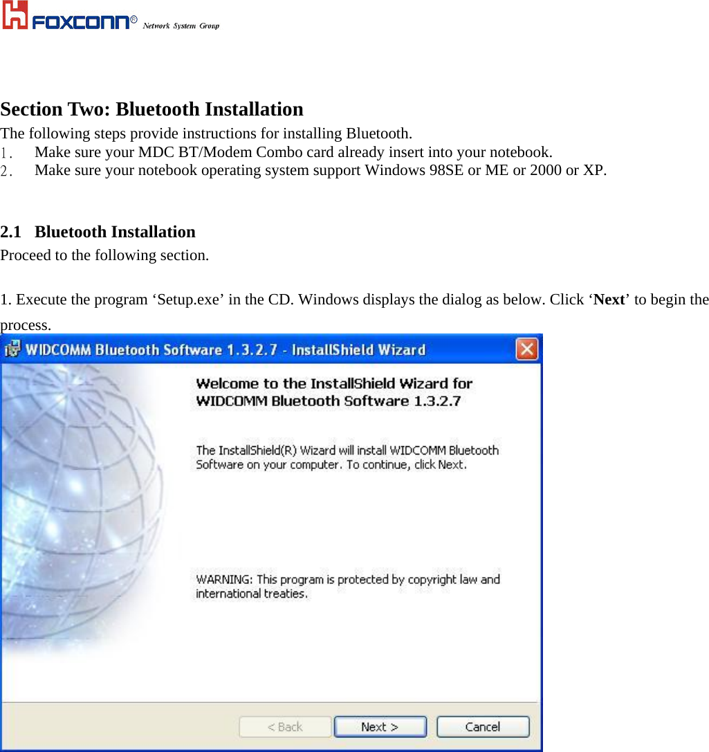
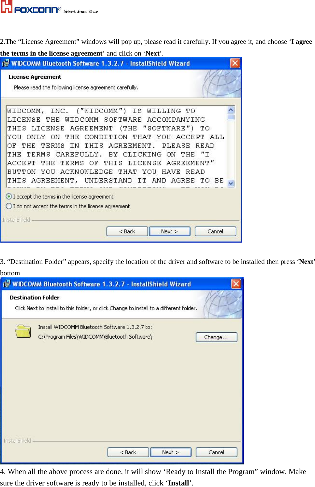
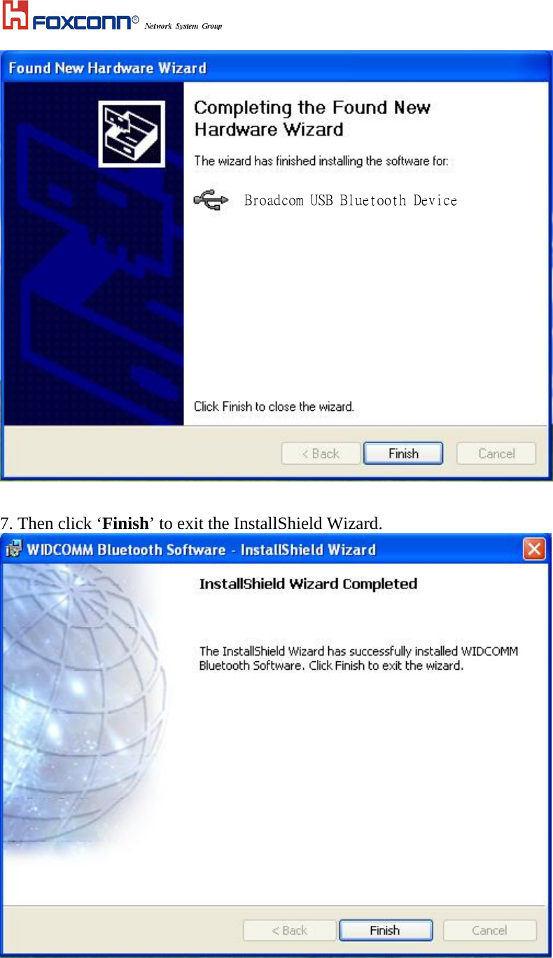
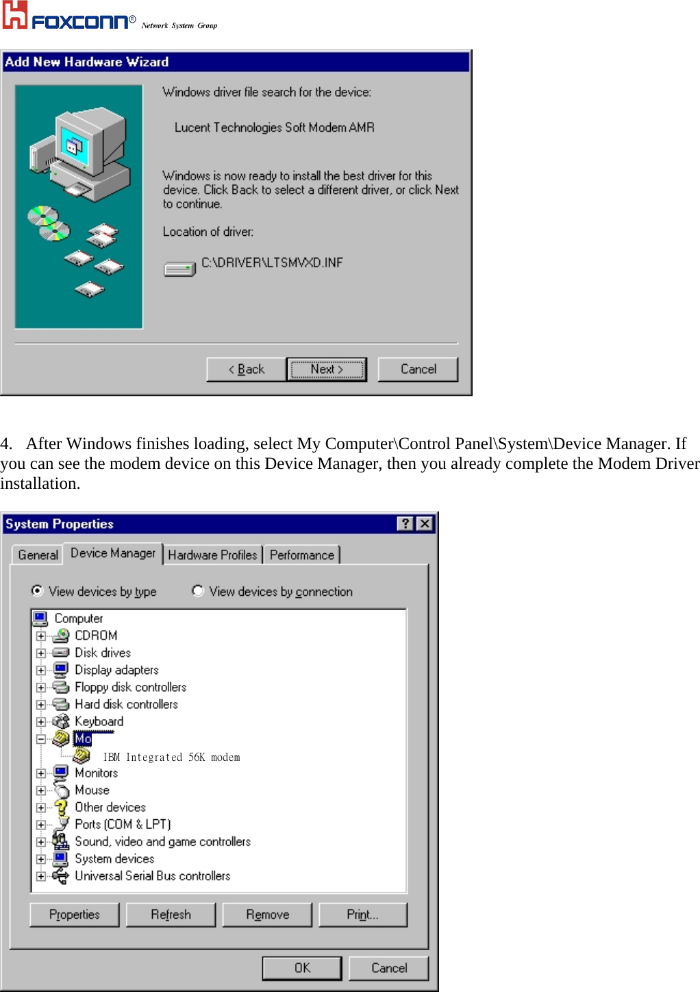
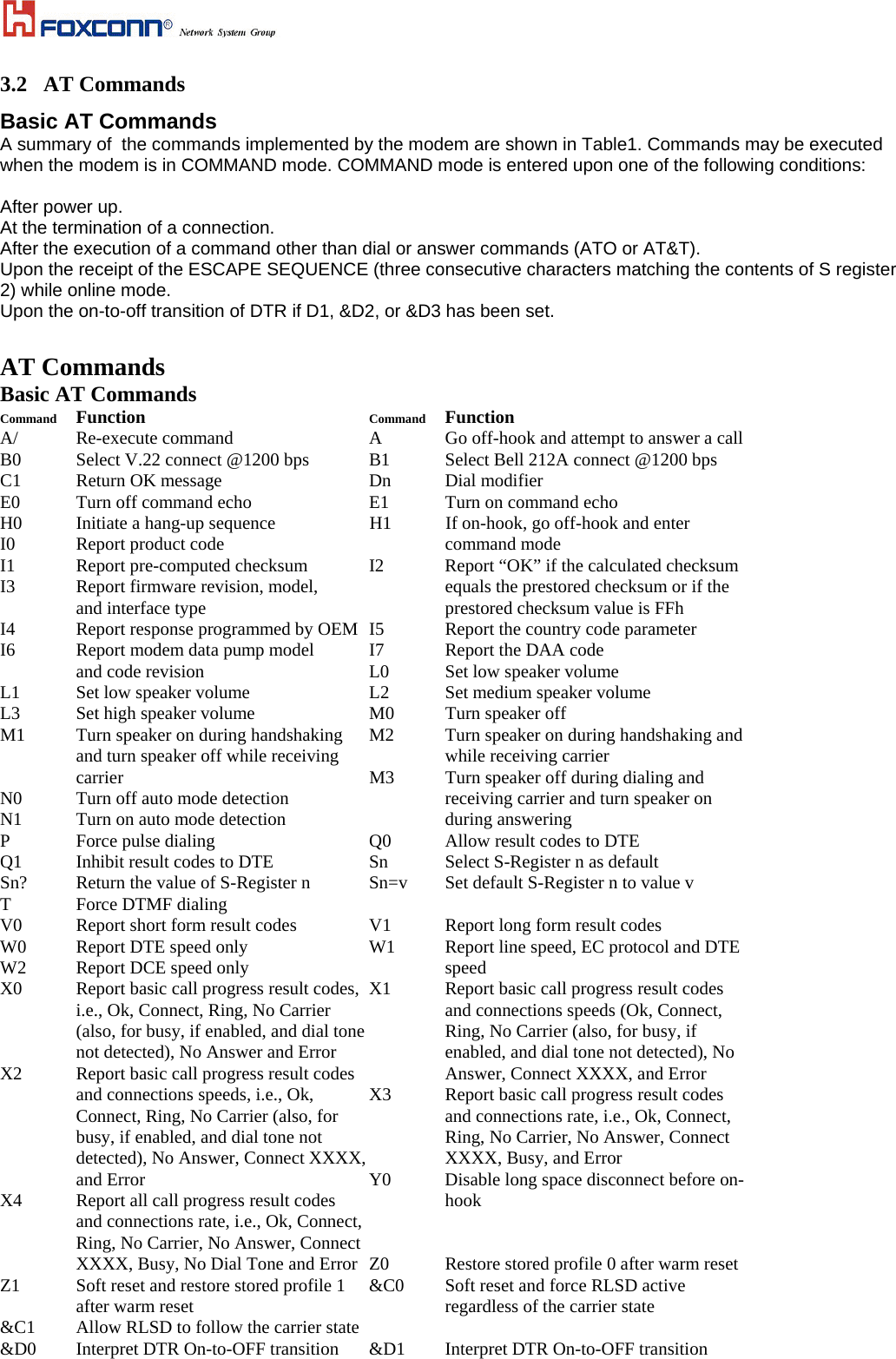
![5.Choose ‘Install the software automatically [Recommened]’, then Click ‘Next’ to continue. 6. Congratulations! Bluetooth has been installed successfully. Please click ‘Finish’ to confirm the completion of installation. Broadcom USB Bluetooth Device](https://usermanual.wiki/HON-HAI-PRECISION-IND/J07M067/User-Guide-493841-Page-7.png)
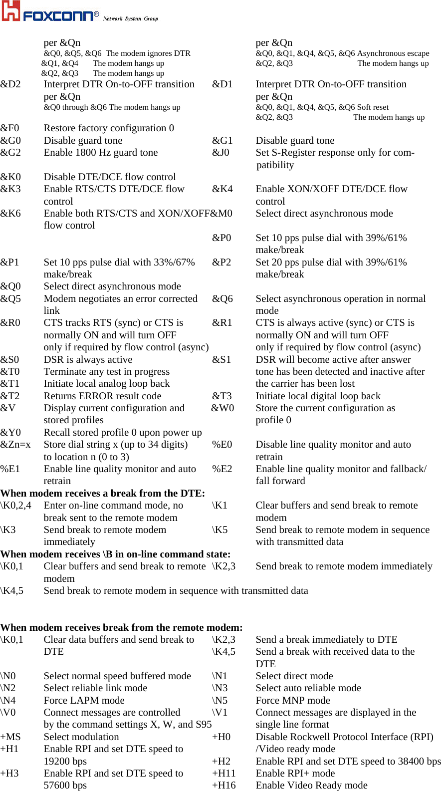
![**0 Download to flash memory at last **1 Download to flash memory at 38.4 kbps sensed speed **2 Download to flash memory at 57.6 kbps -SDR=0 Disable distinctive ring -SDR=1 Enable distinctive ring type 1 -SDR=2 Enable distinctive ring type 2 -SDR=3 Enable distinctive ring type 1 and 2 -SDR=4 Enable distinctive ring type 3 -SDR=5 Enable distinctive ring type 1 and 3 -SDR=6 Enable distinctive ring type 2 and 3 -SDR=7 Enable distinctive ring type 1, 2 and 3 ECC Commands %C0 Disable data compression %C1 Enable MNP 5 data compression \A0 Set maximum block size in MNP to 64 \A1 Set maximum block size in MNP to 128 \A2 Set maximum block size in MNP to 192 \A3 Set maximum block size in MNP to 256 \Bn Send break of n x 100 ms MNP 10 Commands -K0 Disable MNP 10 extended services -K1 Enable MNP 10 extended services -K2 Disable MNP 10 extended services -SEC=0 Disable MNP 10-EC detection only -SEC=1, [<tx level>] Enable MNP 10-EC and set transmit level<tx level> 0 to 30 (0 dBm to -30 dBm) FAX Class 1 +Fclass=1 Service class +FAE=0 Disable data/fax auto answer +FAE=1 Enable data/fax auto answer +FRH=n Receive data with HDLC framing +FRM=n Receive data +FRS=n Receive silence, nx10 ms +FTH=n Transmit data with HDLC framing +FTM=n Transmit data +FTS=n Stop transmission and wait, nx10 ms V.92 Command set 1.AT%TT61 V.92 generate V.92 PCM upstream signal for PTT testing. 2.AT+PQC=255 to clear all stored fast connect profiles.](https://usermanual.wiki/HON-HAI-PRECISION-IND/J07M067/User-Guide-493841-Page-14.png)