HON HAI PRECISION IND J20H018 802.11b/g WLAN Module User Manual
HON HAI Precision Ind. Co., Ltd. 802.11b/g WLAN Module
UserManual.wiki
>
HON HAI PRECISION IND
>
J20H018 User Manual
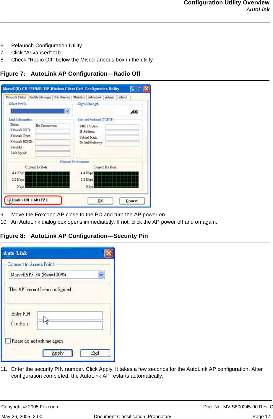
User Manual
Navigation menu
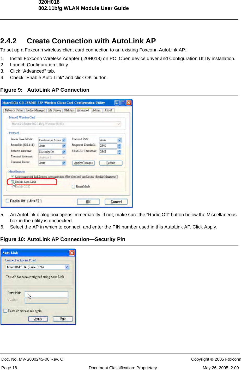
Upload a User Manual
Namespaces
Wiki Guide
HTML
PDF
Info
Views
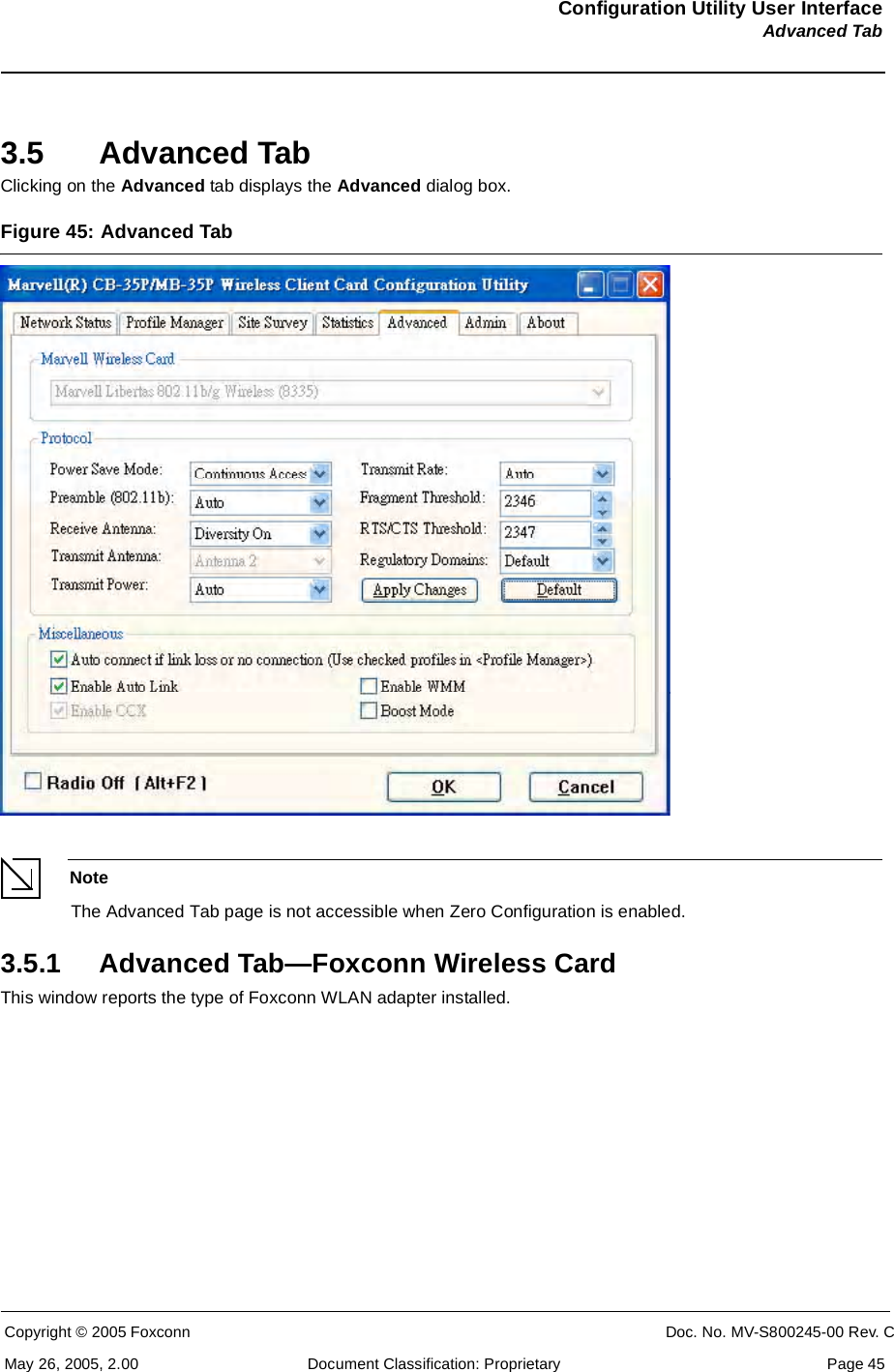
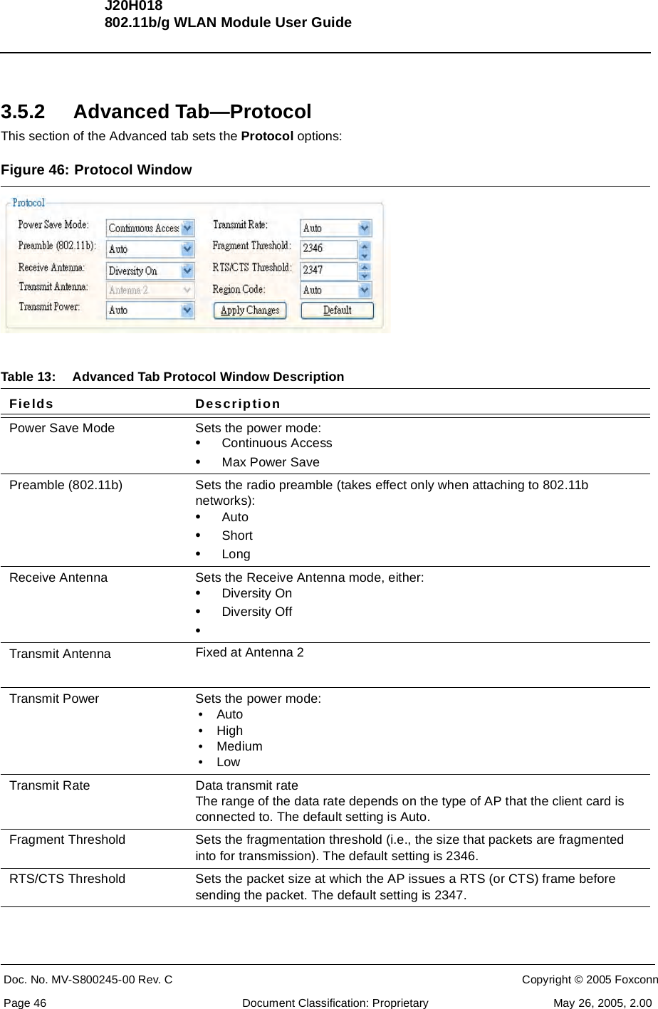
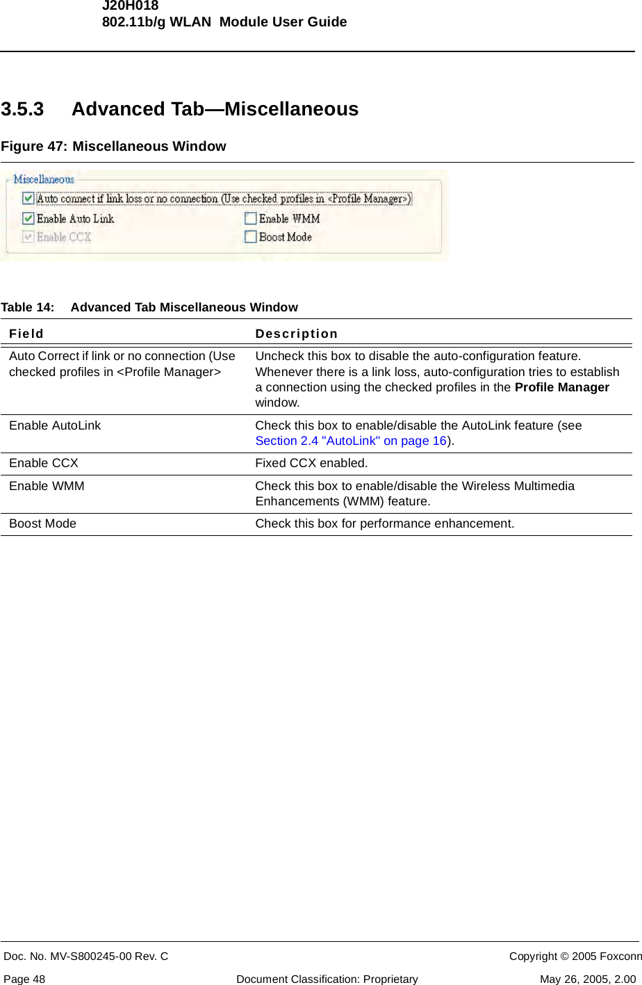
User Manual
Discussion / Help
Navigation
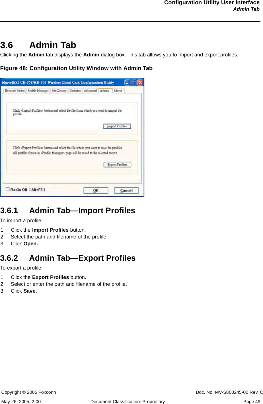
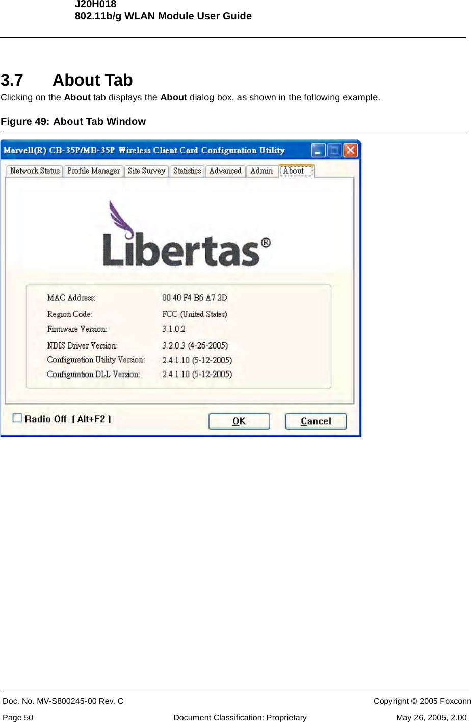
![IC statement "This device has been designed to operate with an antenna having a maximum gain of [2] dB. Antenna having a higher gain is strictly prohibited per regulations of Industry Canada. The required antenna impedance is [ 50 ] ohms." "To reduce potential radio interference to other users, the antenna type and its gain should be so chosen that the equivalent isotropically radiated power (EIRP) is not more than that required for successful communication".](https://usermanual.wiki/HON-HAI-PRECISION-IND/J20H018/User-Guide-571496-Page-56.png)