HON HAI PRECISION IND J20H077 Bluetooth Module User Manual
HON HAI Precision Ind. Co., Ltd. Bluetooth Module
UserManual.wiki
>
HON HAI PRECISION IND
>
J20H077 User Manual
User Manual.pdf
Navigation menu
Upload a User Manual
Namespaces
Wiki Guide
HTML
PDF
Info
Views
User Manual
Discussion / Help
Navigation
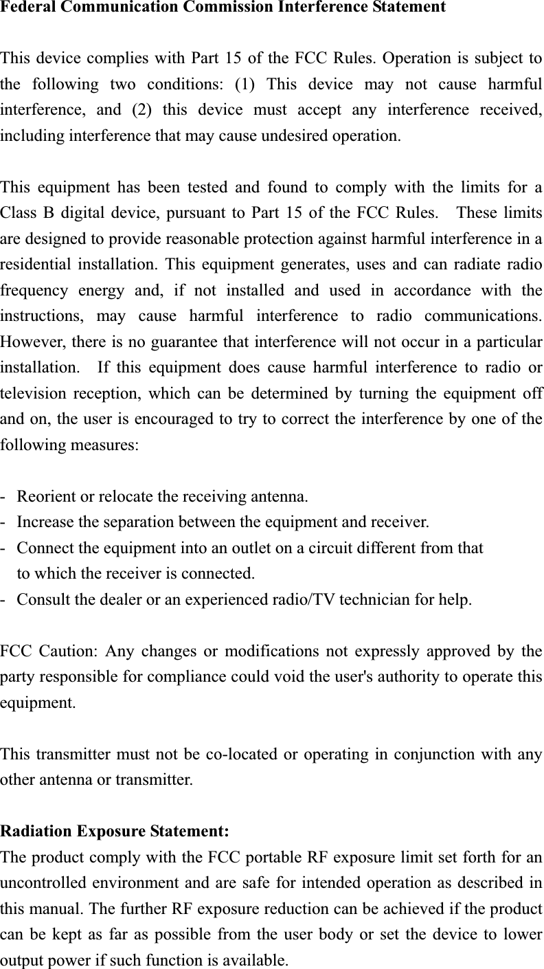
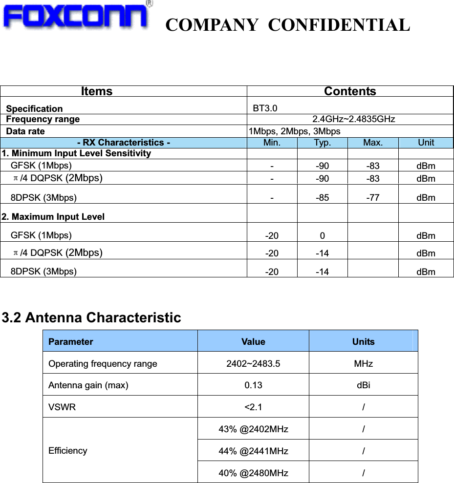
![COMPANY CONFIDENTIAL ContentSection1 Introduction ..............................................................................................................3 1. Product Overview ................................................................................................................3 1.1 Application scope..................................................................................................... 3 1.2 Block Diagram.......................................................................................................... 3 1.3 Features .................................................................................................................... 4 1.4 Interface and Connector......................................................................................... 4 2. Electrical Specification ........................................................................................................5 2.1 Recommended operating rating............................................................................ 5 2.2 DC Characteristics .................................................................................................. 5 2.3 ESD Information ...................................................................................................... 5 2.4 Environment Storage Condition ............................................................................ 5 3. RF Specification ...................................................................................................................6 3.1 Bluetooth 3.0 ............................................................................................................ 6 3.2 Antenna Characteristic............................................................................................ 7 4. Mechanical Specifications ...................................................................................................8 4.1 PCB Assembly Dimension ..................................................................................... 8 Section2 WinXP utility and install .........................................................................................9 5. Overview ...............................................................................................................................9 6. Requirements........................................................................................................................9 7. USB to UART Interface Driver Install ..............................................................................9 8. Test Tool Install .................................................................................................................11 8.1 ActivePerl-5[1].8.4.810-MSWin32-x86.msi install............................................. 11 8.2 dotnetfx.exe install................................................................................................. 12 8.3 setup_for 20702A1.exe ........................................................................................ 12 9. Blue Tool Test Setting ........................................................................................................14 9.1 Tx Mode .................................................................................................................. 14 9.2 Rx Mode.................................................................................................................. 19](https://usermanual.wiki/HON-HAI-PRECISION-IND/J20H077/User-Guide-2025542-Page-2.png)
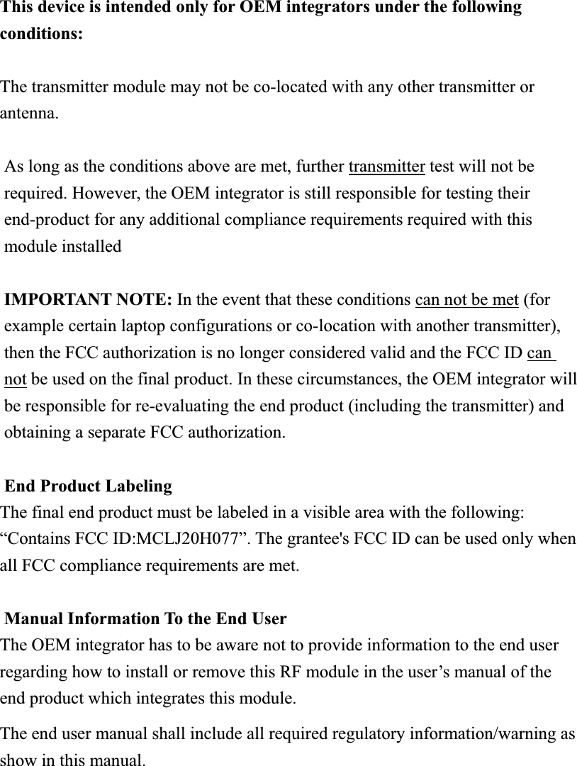
![COMPANY CONFIDENTIAL 3. RF Specification 3.1 Bluetooth 3.0 Items Contents - TX Characteristics - Min. Typ. Max. Unit1. Power Levels ʳBT Output Power (Basic Data Rate) -1 1 3 dBm 2. Initial Carrier Frequency Tolerance Average Offset -75 6 75 kHz 3. Carrier Drift Drift Rate DH1 -20 -4 20 kHz/50usDH3 -20 -4 20 kHz/50usDH5 -20 -5 20 kHz/50usAverage Drift DH1 -25 -1 25 kHz DH3 -40 0 40 kHzDH5 -40 0 40 kHz4. Modulation Characteristic F1avg 140 150 175 kHz F2max 115 140 kHzF1/F2 Ratio 0.8 0.96 5. EDR Relative Transmit Power 2Mbps: P[DQPSK]-P[GFSK] -4 0.25 1 dB3Mbps: P[8DPSK]-P[GFSK] -4 0.25 1 dB6. EDR Carrier Frequency Stability and Modulation Accuracy 2Mbps:±/4 DQPSK Initial Frequency Error: i-75 -3 75 kHzFrequency Error: 0-10 -2 10 kHzBlock Frequency Error: i + 0-75 -5 75 kHzRMS DEVM - 0.05 0.2 Peak DEVM - 0.12 0.35 99% DEVM (% Symbols <=0.3) 99% 100% 3Mbps:8DPSK Initial Frequency Error: i-75 -9 75 kHzFrequency Error: 0-10 -1.5 10 kHzBlock Frequency Error: i + 0-75 -10 75 kHzRMS DEVM - 0.05 0.13 Peak DEVM - 0.13 0.25 99% DEVM (% Symbols <=0.13) 99% 100%](https://usermanual.wiki/HON-HAI-PRECISION-IND/J20H077/User-Guide-2025542-Page-6.png)
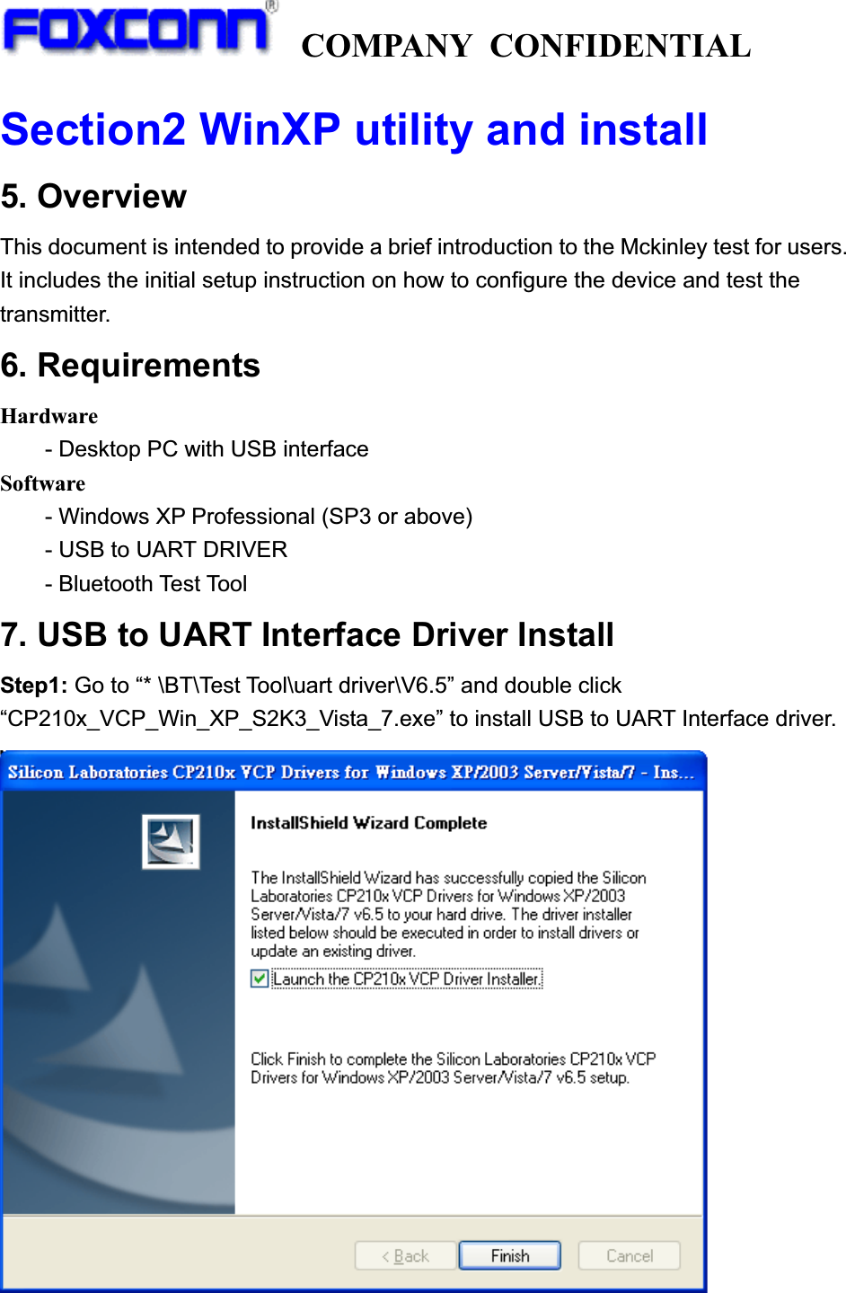
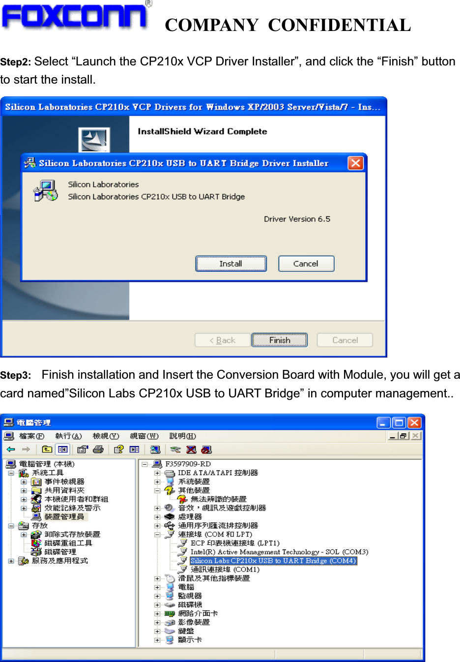
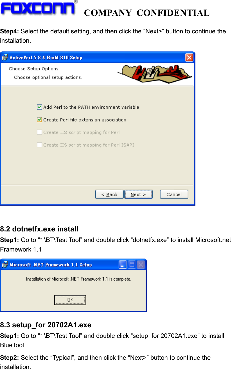
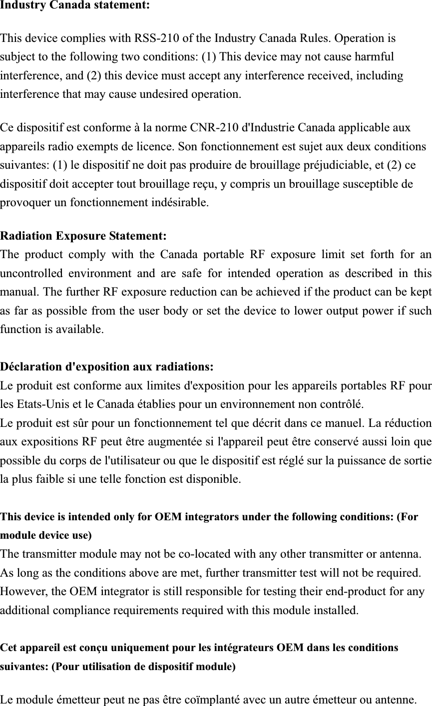
![COMPANY CONFIDENTIAL 8. Test Tool Install 8.1 ActivePerl-5[1].8.4.810-MSWin32-x86.msi install Step1: Go to “* \BT\Test Tool” and double click “ActivePerl-5[1].8.4.810-MSWin32-x86.msi” to install Step2: Select the default setting, and then click the “Next>” button to show the next page. Step3: Select ”Enable PPM3 to send profile info to ASPN ”, and then click the “Next>” button to show the next page.](https://usermanual.wiki/HON-HAI-PRECISION-IND/J20H077/User-Guide-2025542-Page-11.png)