HON HAI PRECISION IND M26H002 WIFI/BT Combo wireless module User Manual M26H002
HON HAI Precision Ind. Co., Ltd. WIFI/BT Combo wireless module M26H002
UserManual.wiki
>
HON HAI PRECISION IND
>
M26H002 User Manual
M26H002_user manual
Navigation menu
Upload a User Manual
Namespaces
Wiki Guide
HTML
PDF
Info
Views
User Manual
Discussion / Help
Navigation
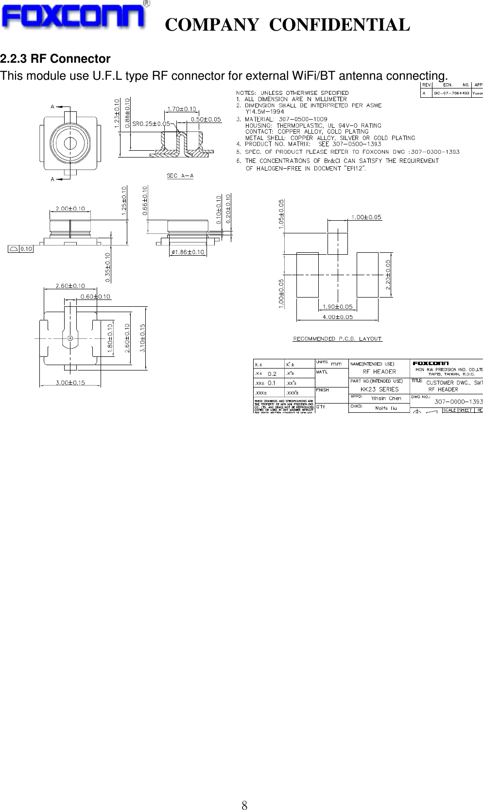
![COMPANY CONFIDENTIAL 7 Here is the pin-out signals of module’s connector. The pin number is refer to “Item2.2.1 module dimension”. Table 1: Host-Module Connector Pin-out Signals Pin-Out No. No. Pin-Out 3V3 1 2 SD_CLK 3V3 3 4 GND GND 5 6 SD_D0 RESET# 7 8 SD_D1 SLEEP_CLK (32.768kHz) 9 10 GND GND 11 12 SD_D2 SD_CMD 13 14 SD_D3 PDn 15 16 GND GND 17 18 HOST_WAKEUP_DEV VIO 19 20 VIO *Note, Pin18[HOST_WAKEUP_DEV] of connector is connected with the pinM11[GPIO4] of 88W8787 TFBGA IC. It can be configured to IO input or IO output for wake-up application.](https://usermanual.wiki/HON-HAI-PRECISION-IND/M26H002/User-Guide-1912251-Page-7.png)