HON HAI PRECISION IND T77H566 WiFi/BT Module User Manual 802
HON HAI Precision Ind. Co., Ltd. WiFi/BT Module 802
UserManual.wiki
>
HON HAI PRECISION IND
>
T77H566 User Manual
User Manual rev.pdf
Navigation menu
Upload a User Manual
Namespaces
Wiki Guide
HTML
PDF
Info
Views
User Manual
Discussion / Help
Navigation
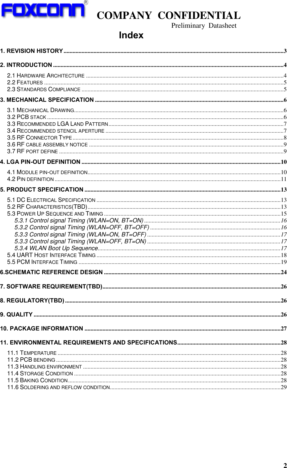
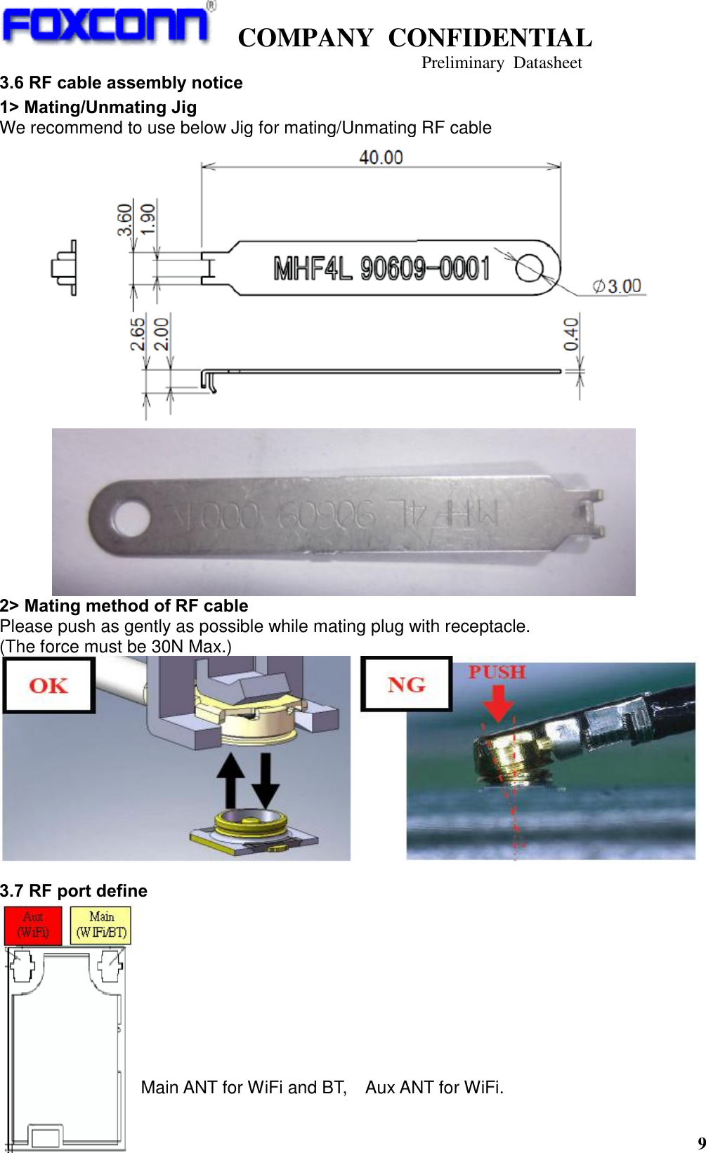
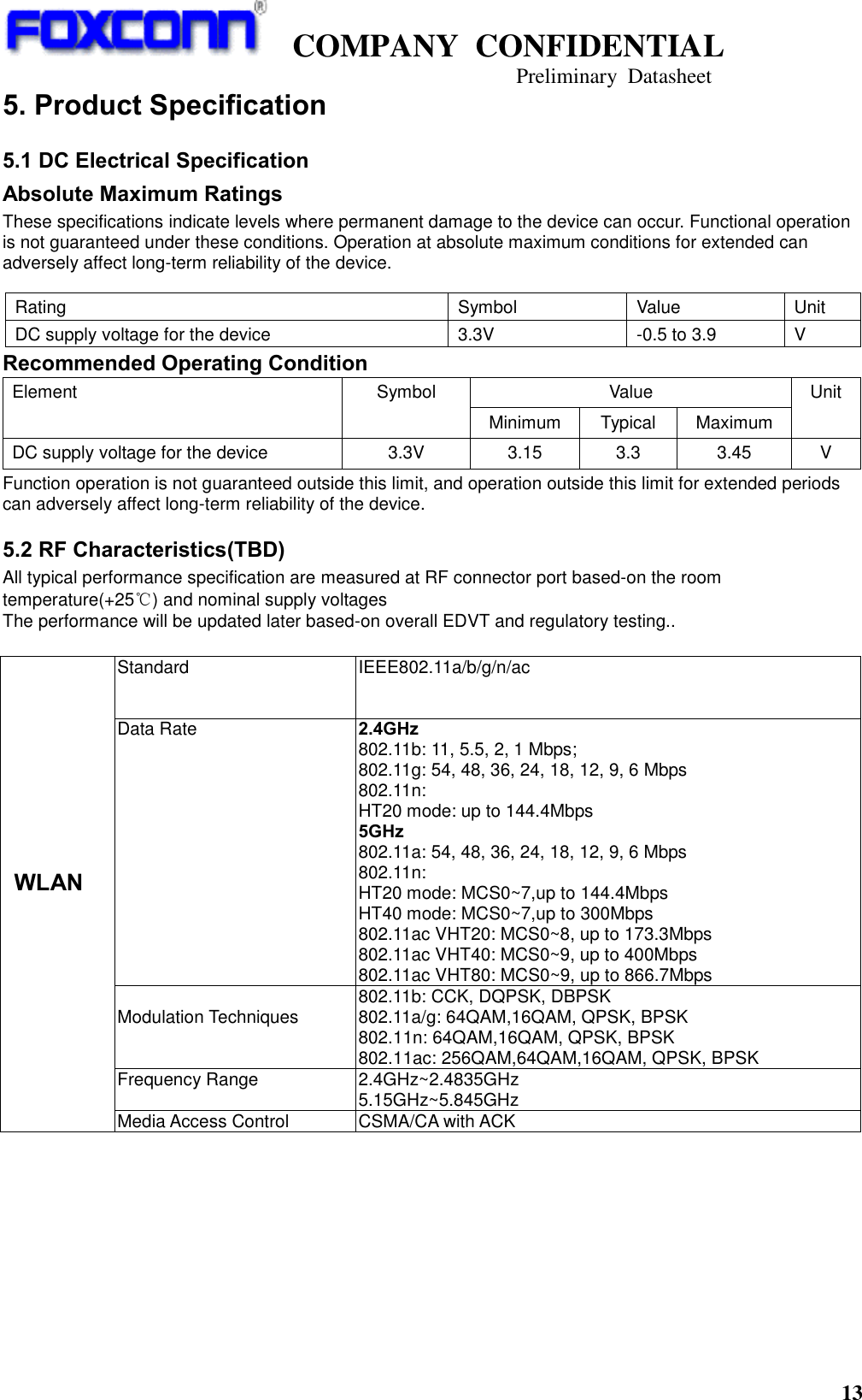
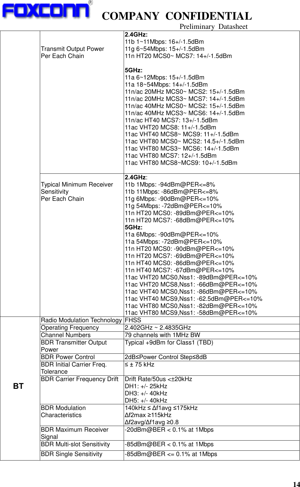
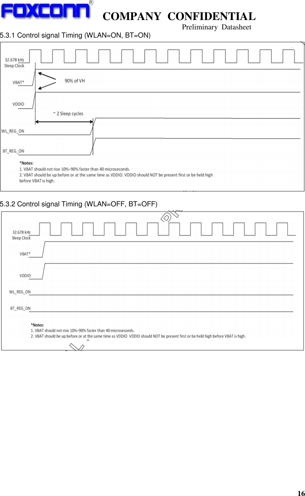
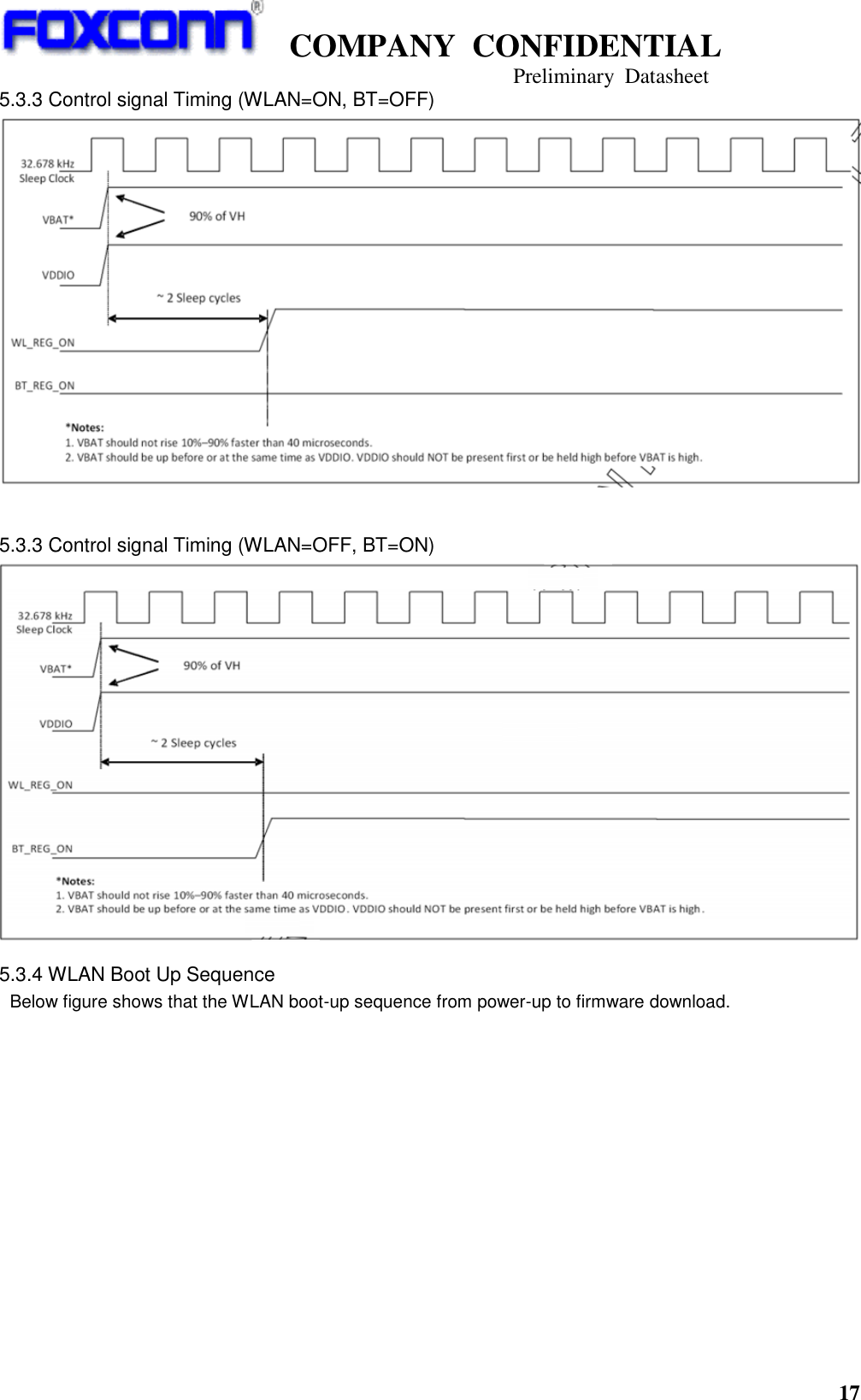
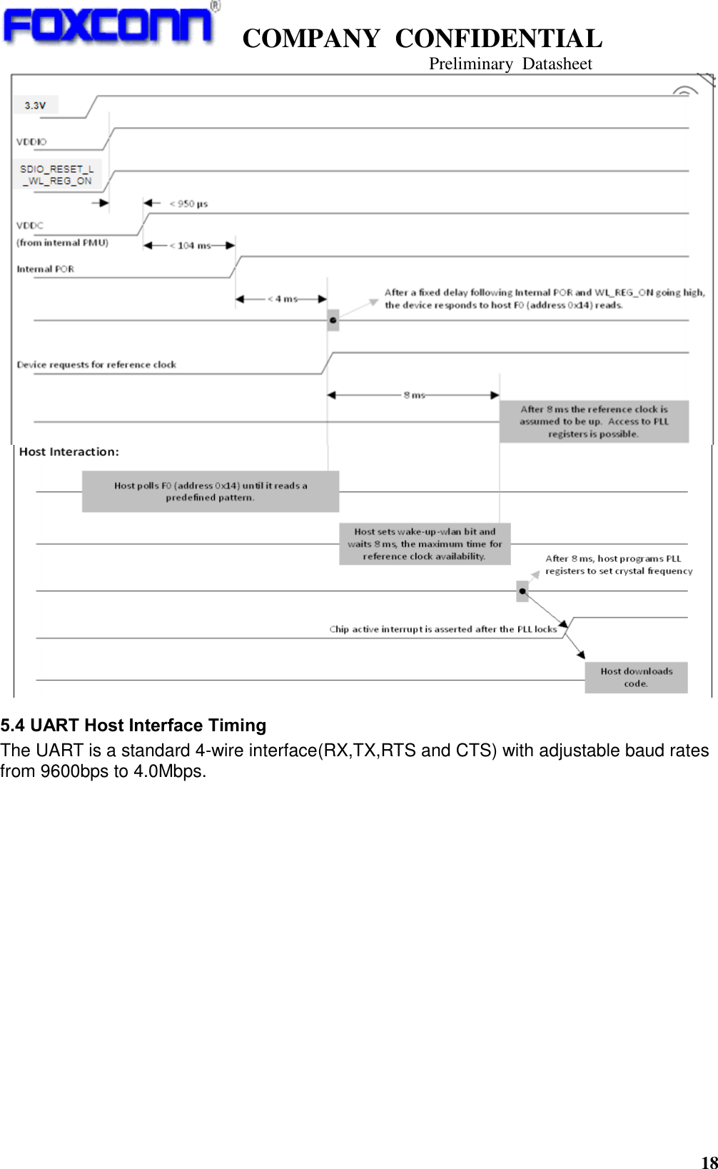
![COMPANY CONFIDENTIAL Preliminary Datasheet 15 EDR Relative Power P[GFSK]-4dB<P[DPSK]< P[GFSK]+1dB EDR Stability and Mod Accuracy -75 kHz <ωi < 75 kHz -10kHz<ω0 <10kHz RMS DEVM<=0.13 for all 8DPSK @3Mbps Peak DEVM<=0.25 for all 8DPSK @3Mbps 99% DEVM<=0.2 for 99% 8DPSK @3Mbps BDR Frequency Range FL>2.4GHz,FH<2.4835GHz EDR Sensitivity -86dBm@BER <= 0.01% at 2Mbps -79dBm@BER <= 0.01% at 3Mbps BDR TX Output Spectrum -20dB Bandwidth ≤1MHz LE Output Power <10dBm LE Modulation Characteristics 225kHz ≤ Δf1avg ≤275kHz; Δf2max ≥185kHz for at least 99.9% test packets; Δf2avg/Δf1avg ≥0.8 LE Carrier frequency offset and drift Carrier frequency offset: ±150kHz Carrier Drift: ≤50kHz Drift rate: ≤20kHz/50us LE Receiver Sensitivity -85dBm@PER <= 30.8% 5.3 Power Up Sequence and Timing The BCM4356 has two signals WL_REG_ON [pin45] & BT_REG_ON [pin63] that allows the host to control the power consumption by enabling or disabling the Bluetooth, WLAN and internal regulator blocks. Below timing diagram are provided to indicate proper sequencing of the signals for various operational states. WL_REG_ON [pin45] Used by the PMU to power up the WLAN section. It’s also OR-gated with BT_REG_ON input to control the internal BCM4356 regulators. When this pin is high, the regulatory are enabled and the WLAN section is out of reset. When this pin is low, the WLAN section is in reset. If both the BT_REG_ON and WLAN_REG_ON pins are low, the regulators are disable. BT_REG_ON [pin63] Used by the PMU(OR-gated with WL_REG_ON) to power up the internal BCM4356 regulators. If both the BT_REG_ON and WLAN_REG_ON pins are low, the regulators are disable. When this pin is high, the regulatory are enabled and the BT section is out of reset. When this pin is low, the BT section is in reset. Remark: VBAT means DC input 3.3V in below timing diagram.](https://usermanual.wiki/HON-HAI-PRECISION-IND/T77H566/User-Guide-2537285-Page-15.png)
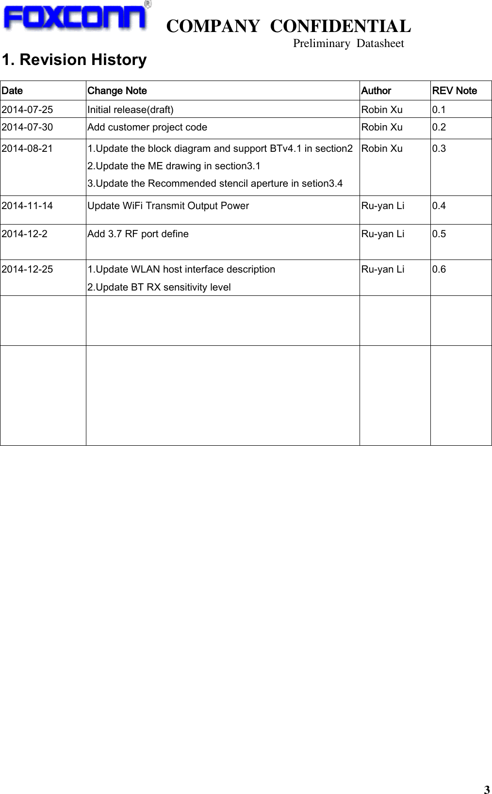
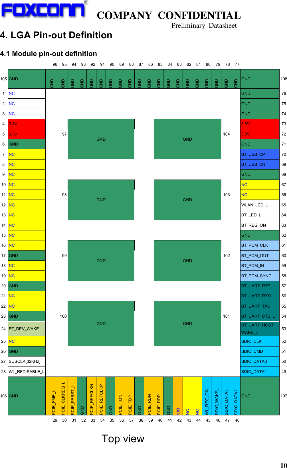
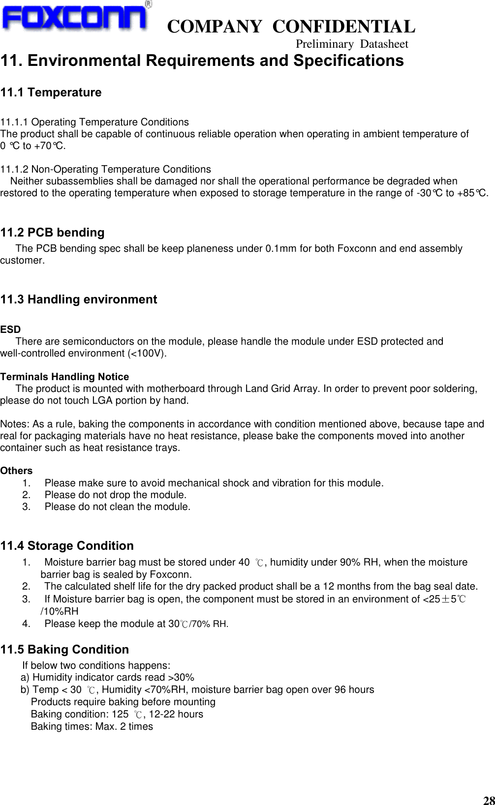
![COMPANY CONFIDENTIAL Preliminary Datasheet 26 7. Software Requirement(TBD) - Operating System Support Windows 8 Windows Blue or later Android 4.3 and above - WLAN Feature Support WiFi Direct WiFi Display Wi-Fi Miracast (Intel will support WiDi with Miracast interoperability) - WLAN Security Support WPA/WPA2 Enterprise CCX Lite or higher WMM/AES/TKIP/CKIP - WLAN Transmit Power Reduction Software control to meet FCC SAR requirement Capability to disable 5GHz operation - Bluetooth Profile Support Advanced Audio Distribution Profile(A2DP) Basic Imaging Profile (BIP) Basic Printing Profile( BPP) General Audio/Video Distribution Profile (GAVDP ) Generic Object Profile(GOEP) Hands-Free Profile(HFP) Headset Profile(HSP) Human Interface Device Profile(HID)[2.0/4.0] Object Push Profile (OPP) Service Port Profile(SPP) Personal Area Network Profile(PAN) - BLE (Bluetooth Low Energy) Support Windows 8 Windows Blue or later 8. Regulatory(TBD) The module shall pass below RF certification based-on customer requirement. USA : FCC P15B / FCC P15C / FCC P15E (FCC ID: TBD) Canada : IC RSS-210 (IC ID: TBD) Japan : TELEC EU : EN300328 V1.8.1 , EN301893 V1.6.1 , EN301489-1/-17 , EN 60950-1 2nd 9. Quality The product quality must be followed-up by Foxconn factory quality control system.](https://usermanual.wiki/HON-HAI-PRECISION-IND/T77H566/User-Guide-2537285-Page-26.png)

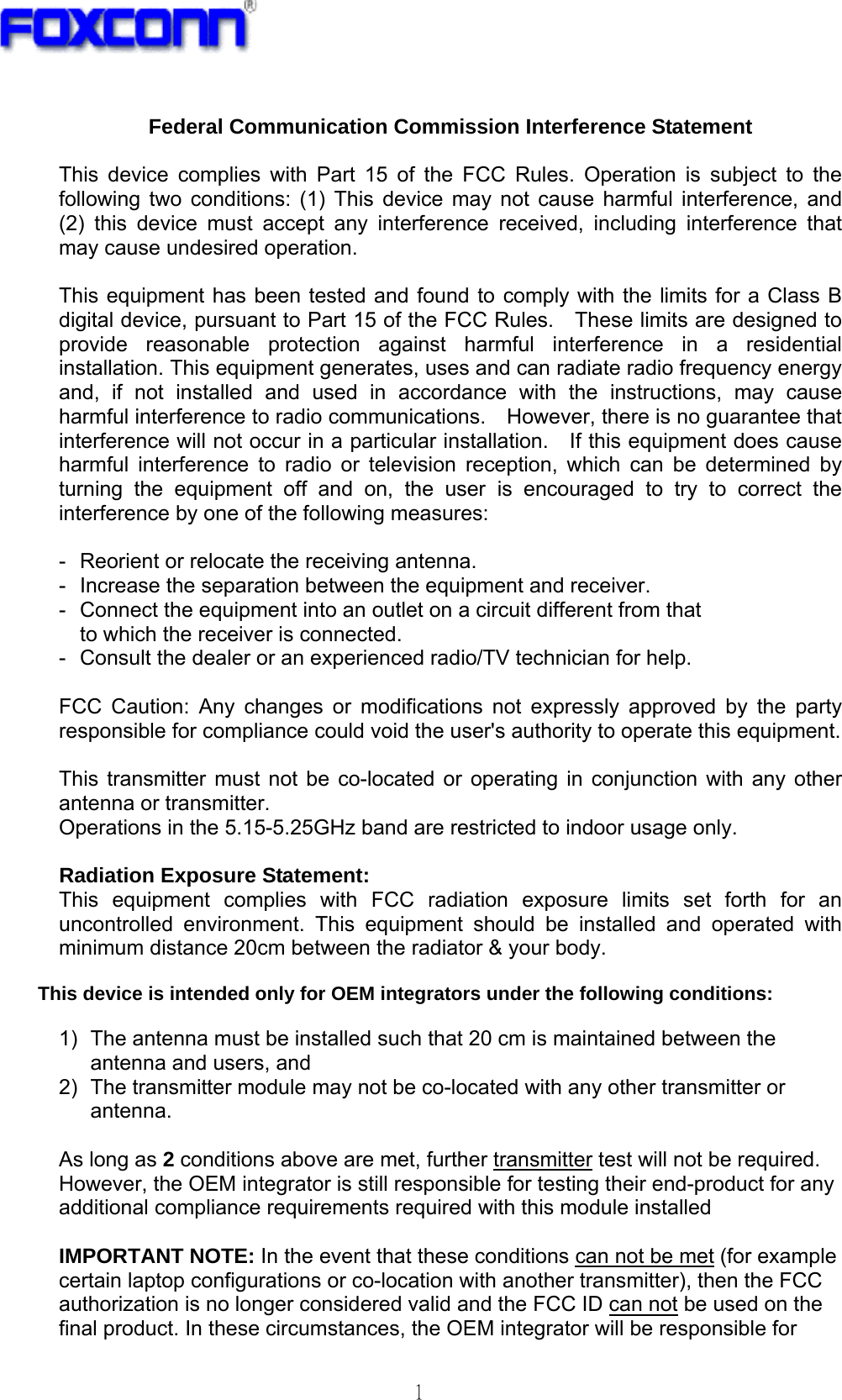
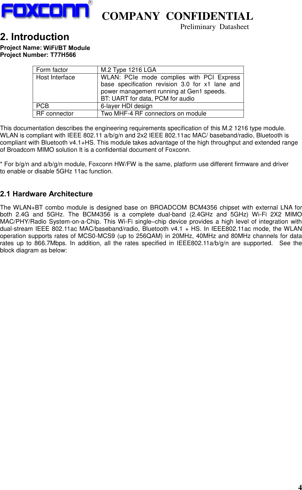
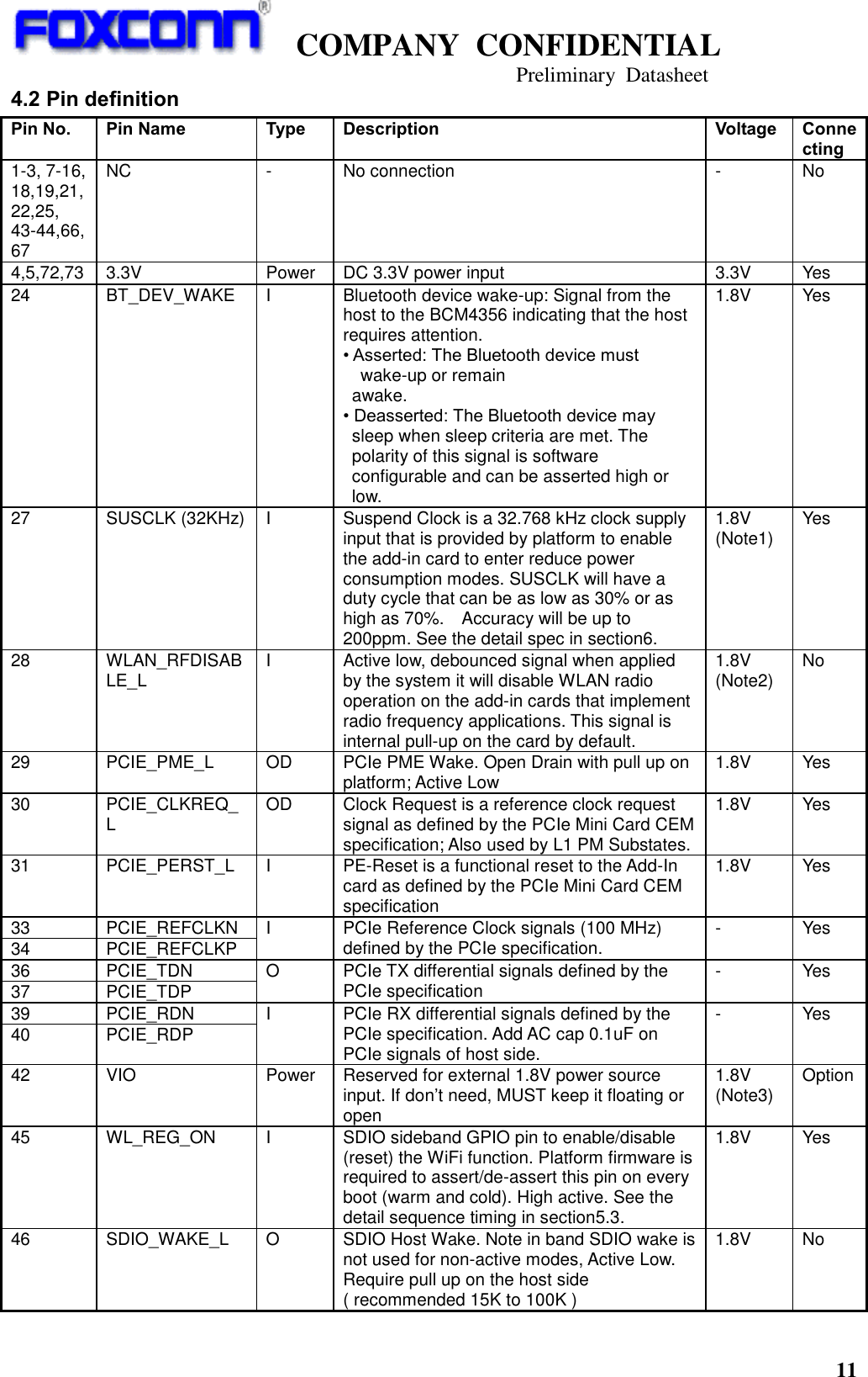
![5 - EN 300 328 V1.8.1: 2012 Electromagnetic compatibility and Radio spectrum Matters (ERM); Wideband Transmission systems; Data transmission equipment operating in the 2,4 GHz ISM band and using spread spectrum modulation techniques; Harmonized EN covering essential requirements under article 3.2 of the R&TTE Directive - EN 301 893 V1.7.1: 2012 Broadband Radio Access Networks (BRAN); 5 GHz high performance RLAN; Harmonized EN covering essential requirements of article 3.2 of the R&TTE Directive - EN 301 489-1 V1.9.2: 2011 Electromagnetic compatibility and Radio Spectrum Matters (ERM); ElectroMagnetic Compatibility (EMC) standard for radio equipment and services; Part 1: Common technical requirements - EN 301 489-17 V2.2.1: 2012 Electromagnetic compatibility and Radio spectrum Matters (ERM); ElectroMagnetic Compatibility (EMC) standard for radio equipment and services; Part 17: Specific conditions for 2,4 GHz wideband transmission systems and 5 GHz high performance RLAN equipment Česky [Czech] [Jméno výrobce] tímto prohlašuje, že tento [typ zařízení] je ve shodě se základními požadavky a dalšími příslušnými ustanoveními směrnice 1999/5/ES. Dansk [Danish] Undertegnede [fabrikantens navn] erklærer herved, at følgende udstyr [udstyrets typebetegnelse] overholder de væsentlige krav og øvrige relevante krav i direktiv 1999/5/EF. Deutsch [German] Hiermit erklärt [Name des Herstellers], dass sich das Gerät [Gerätetyp] in Übereinstimmung mit den grundlegenden Anforderungen und den übrigen einschlägigen Bestimmungen der Richtlinie 1999/5/EG befindet. Eesti [Estonian] Käesolevaga kinnitab [tootja nimi = name of manufacturer] seadme [seadme tüüp = type of equipment] vastavust direktiivi 1999/5/EÜ põhinõuetele ja nimetatud direktiivist tulenevatele teistele asjakohastele sätetele. English Hereby, [name of manufacturer], declares that this [type of equipment] is in compliance with the essential requirements and other relevant provisions of Directive 1999/5/EC. Español [Spanish] Por medio de la presente [nombre del fabricante] declara que el [clase de equipo] cumple con los requisitos esenciales y cualesquiera otras disposiciones aplicables o exigibles de la Directiva 1999/5/CE. Ελληνική [Greek] ΜΕ ΤΗΝ ΠΑΡΟΥΣΑ [name of manufacturer] ΔΗΛΩΝΕΙ ΟΤΙ [type of equipment] ΣΥΜΜΟΡΦΩΝΕΤΑΙ ΠΡΟΣ ΤΙΣ ΟΥΣΙΩΔΕΙΣ ΑΠΑΙΤΗΣΕΙΣ ΚΑΙ ΤΙΣ ΛΟΙΠΕΣ ΣΧΕΤΙΚΕΣ ΔΙΑΤΑΞΕΙΣ ΤΗΣ ΟΔΗΓΙΑΣ 1999/5/ΕΚ. Français [French] Par la présente [nom du fabricant] déclare que l'appareil [type d'appareil] est conforme aux exigences essentielles et aux autres dispositions pertinentes de la directive 1999/5/CE. Italiano [Italian] Con la presente [nome del costruttore] dichiara che questo [tipo di apparecchio] è conforme ai requisiti essenziali ed alle altre disposizioni pertinenti stabilite dalla direttiva 1999/5/CE. Latviski [Latvian] Ar šo [name of manufacturer / izgatavotāja nosaukums] deklarē, ka [type of equipment / iekārtas tips] atbilst Direktīvas 1999/5/EK būtiskajām prasībām un citiem ar to saistītajiem noteikumiem. Lietuvių [Lithuanian] Šiuo [manufacturer name] deklaruoja, kad šis [equipment type] atitinka esminius reikalavimus ir kitas 1999/5/EB Direktyvos nuostatas. Nederlands [Dutch] Hierbij verklaart [naam van de fabrikant] dat het toestel [type van toestel] in overeenstemming is met de essentiële eisen en de andere relevante bepalingen van richtlijn 1999/5/EG. Malti Hawnhekk, [isem tal-manifattur], jiddikjara li dan [il-mudel tal-prodott] jikkonforma mal-ħtiġijiet essenzjali u ma provvedimenti oħrajn relevanti li hemm fid-Dirrettiva 1999/5/EC.](https://usermanual.wiki/HON-HAI-PRECISION-IND/T77H566/User-Guide-2537285-Page-34.png)
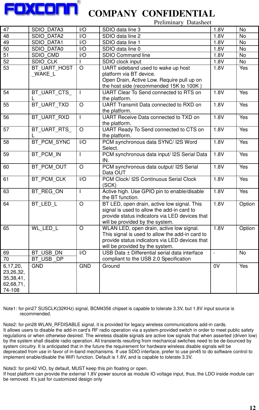
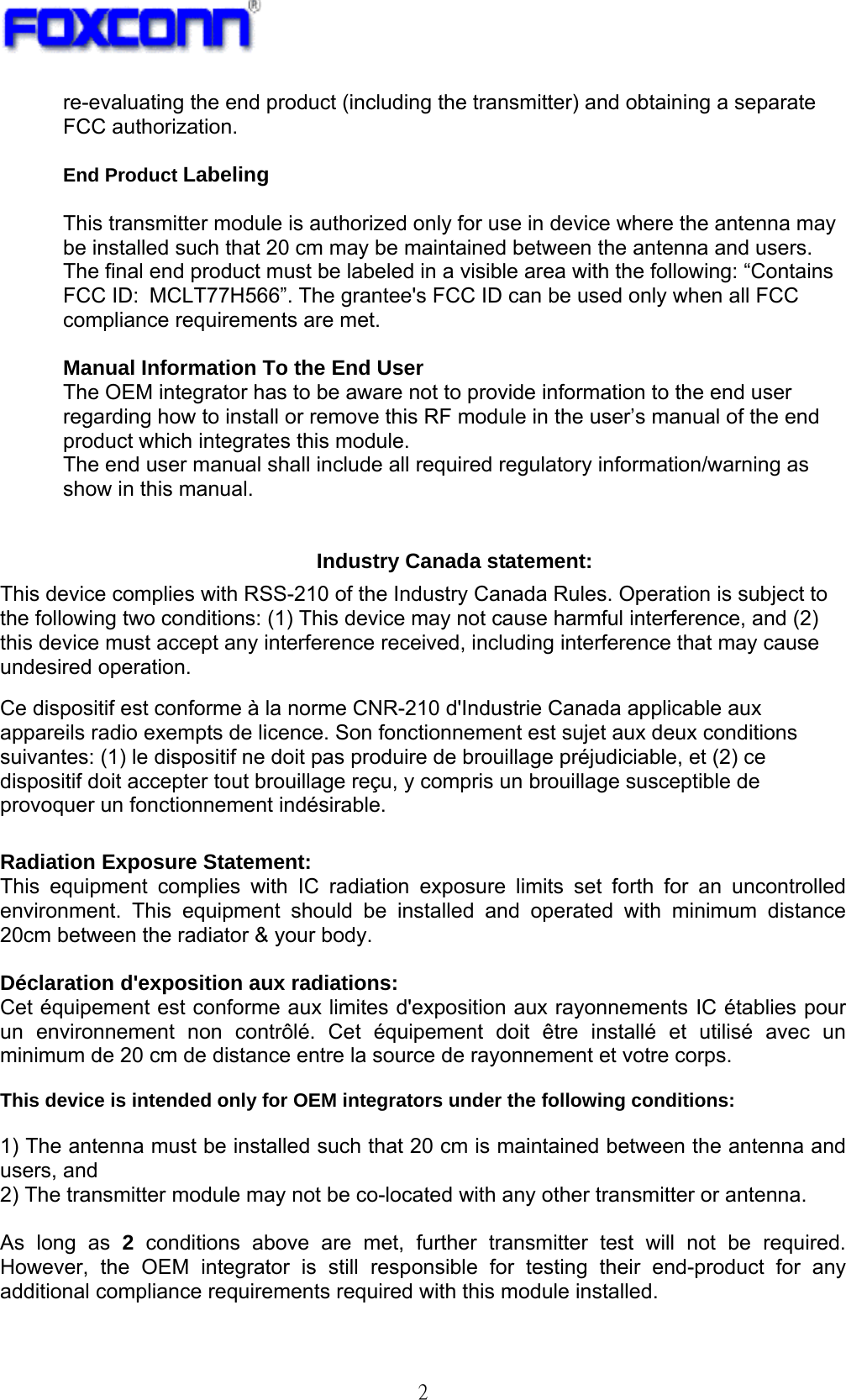
![6 [Maltese] Magyar [Hungarian] Alulírott, [gyártó neve] nyilatkozom, hogy a [... típus] megfelel a vonatkozó alapvetõ követelményeknek és az 1999/5/EC irányelv egyéb elõírásainak. Polski [Polish] Niniejszym [nazwa producenta] oświadcza, że [nazwa wyrobu] jest zgodny z zasadniczymi wymogami oraz pozostałymi stosownymi postanowieniami Dyrektywy 1999/5/EC. Português [Portuguese] [Nome do fabricante] declara que este [tipo de equipamento] está conforme com os requisitos essenciais e outras disposições da Directiva 1999/5/CE. Slovensko [Slovenian] [Ime proizvajalca] izjavlja, da je ta [tip opreme] v skladu z bistvenimi zahtevami in ostalimi relevantnimi določili direktive 1999/5/ES. Slovensky [Slovak] [Meno výrobcu] týmto vyhlasuje, že [typ zariadenia] spĺňa základné požiadavky a všetky príslušné ustanovenia Smernice 1999/5/ES. Suomi [Finnish] [Valmistaja = manufacturer] vakuuttaa täten että [type of equipment = laitteen tyyppimerkintä] tyyppinen laite on direktiivin 1999/5/EY oleellisten vaatimusten ja sitä koskevien direktiivin muiden ehtojen mukainen. Svenska [Swedish] Härmed intygar [företag] att denna [utrustningstyp] står I överensstämmelse med de väsentliga egenskapskrav och övriga relevanta bestämmelser som framgår av direktiv 1999/5/EG. 低功率電波輻射性電機管理辦法 第十二條 經型式認證合格之低功率射頻電機,非經許可,公司、商號或使用者均不得擅自變更頻率、加大功率或變更原設計之特性及功能。 第十四條 低功率射頻電機之使用不得影響飛航安全及干擾合法通信;經發現有干擾現象時,應立即停用,並改善至無干擾時方得繼續使用。 前項合法通信,指依電信法規定作業之無線電通信。 低功率射頻電機須忍受合法通信或工業、科學及醫療用電波輻射性電機設備之干擾。 在5.25-5.35秭赫頻帶內操作之無線資訊傳輸設備,限於室內使用。 1. 本模組於取得認證後將依規定於模組本體標示審驗合格標籤。 2. 系統廠商應於平台上標示「本產品內含射頻模組: XXXyyyLPDzzzz-x」字樣。](https://usermanual.wiki/HON-HAI-PRECISION-IND/T77H566/User-Guide-2537285-Page-35.png)