HONBO AUDIO CHINA EM-100 UHF Wireless Transmitter User Manual EM 100
HONBO AUDIO CHINA LIMITED UHF Wireless Transmitter EM 100
Manual
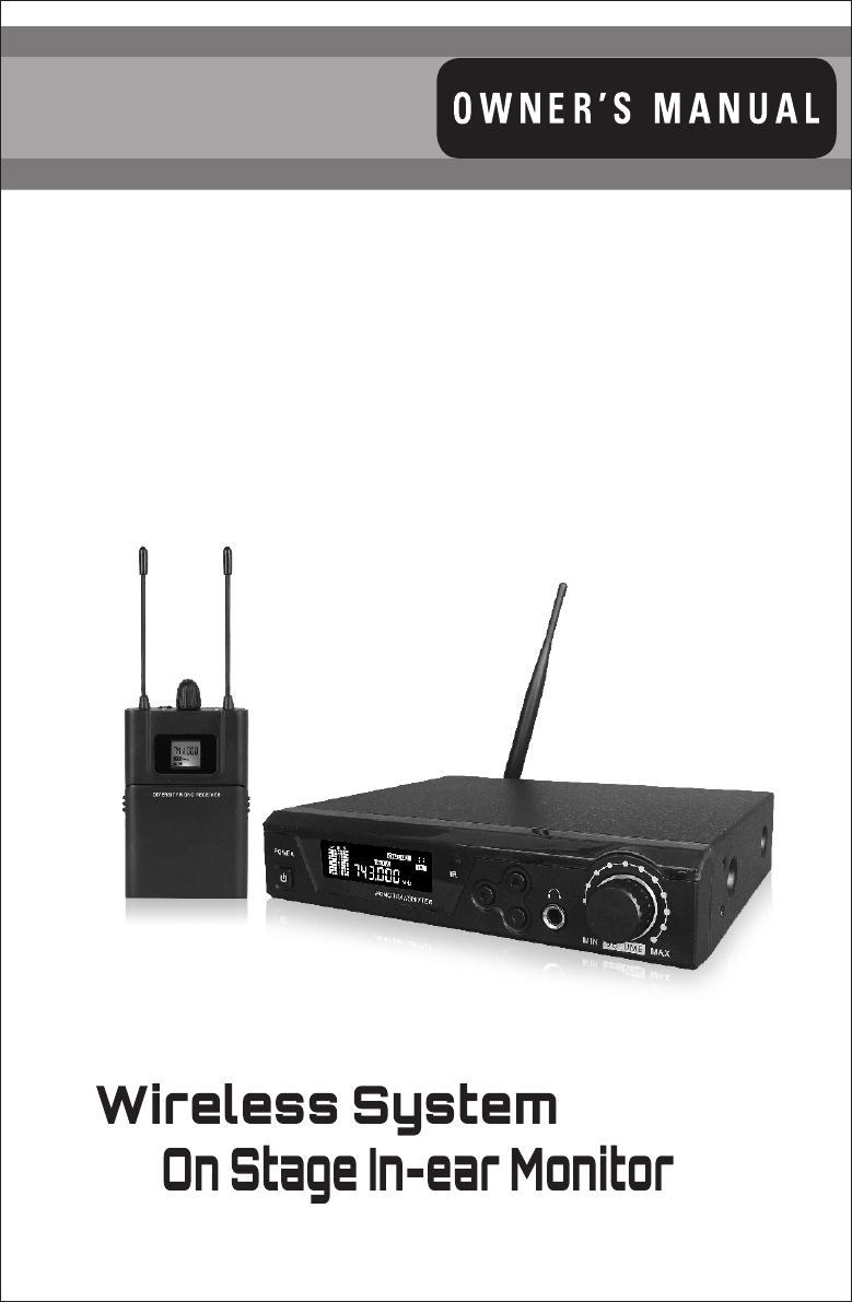
On Stage In-ear Monitor
Wireless System
Diversity
for
UHF Wireless Transmitter
Model: EM-100

Thank you for choosing our wireless In-ear Monitor system, In order to obtain the best
efficiency from the system, you are recommended to read this instruction manual carefully.
Transmitter Features……………………………........................2
Receiver Features………………………..................................4
System Setup…………………………………….........................5
Specifications…………………………………...........................7
Table of Contents
System Components……………………………........................1

System Components
All systems include
Transmitter
6.35mm audio cable
1* TNC antenna
Power supply
Belt-pack Receiver
Earphone
2 x AA Batteries
User guide
System Features
UHF 902.25-926.75MHz frequency range
Mono Outputs, four levels RF output selectable
True diversity for maximum range and dropout protection
PLL Synthesized circuit
Pre-set 100(10*10) selectable frequencies
IR sync downloading the frequency from transmitter
LCD display shows the RF level, AF level, channel and frequency.
EIA standard 1/2U rack-mountable metal chassis
Up to 200m line-of-sight operating range
Designed for professional stage performance applications
1
Transmitter Features
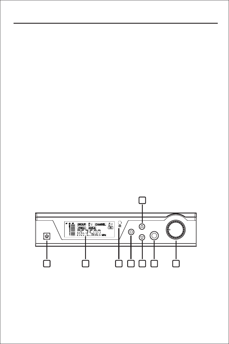
Front Panel
1. Power switch
Tap to turn on, tap to turn off, blue light up when transmitter turns on
2. LCD display
The 63mm*22mm high resolution LCD display shows the group, channel,
frequency, antenna status, AF & RF level and IR set.
3. IR (Infrared) port
Send IR signal to receiver for synchronization
4. UP button
Adjust the frequency, channel, group incrementally
5. SET button
Menu control to set group, channel, frequency, IR Synch.
6. DOWN button
Adjust the frequency, channel, group degressively
7. Volume control
Adjust the volume level, volume knob encircled by blue light
8.Headphone Jack
Headphone output connector 6.3mm jack
2
1 2 3 5 6
4
78
3
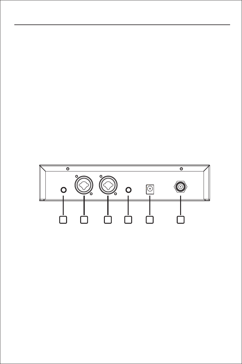
9. Power supply jack (DC12-18V / 500mA)
Connecting the power supply unit
10. 6.35mm (1/4”) audio input jack
Connect the audio source, e.g. of mixer or computer
11 Volume control
Adjust the volume level
12 TNC antennas socket
Connect the high gain antenna
.
.
Back Panel
Transmitter Features
9 1210 1111 10
Body-pack Receiver
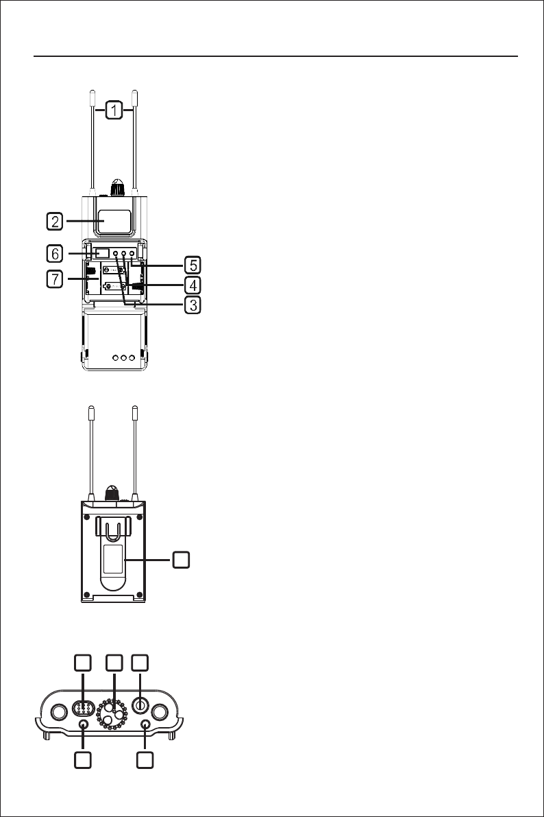
1.Antennas
1/4 wave length wire type antenna, it should be fully
extended during normal operations
2.Backlit LCD
Display frequency and battery life, if the battery
symbol blinks, the battery need to be replaced
immediately
3.UP button
Adjust the frequency, incrementally
4.SET button
Menu control to set frequency
5.DOWN button
Adjust the frequency degressively
6.IR infrared port
Transmitter infrared beam to synchronize frequencies,
hold the receiver with its IR port facing direct to
Transmitter’s IR port in a distance between 5-20cm.
7.Battery compartment
To replace batteries, slightly press the marked
positions on left and right side of the cover and
open forward, make sure to put the battery in the
right polar directions.
8.Earphone audio output
3.5mm earphone audio output socket
9.Volume control
Clockwise to enlarge, counter-clockwise to reduce
10.Light touch power switch
Tap to turn on, long press (2 seconds) to turn off.
11.RF Indicator
Antenna A and B indicator
12.Belt-clip
Clip to the belt
Belt-pack Receiver Features
10
11 11
9 8
12
4
System Setup
1.Connect the included AC power supply to the rear of the receiver and turn on the receiver.
2.Standard Display
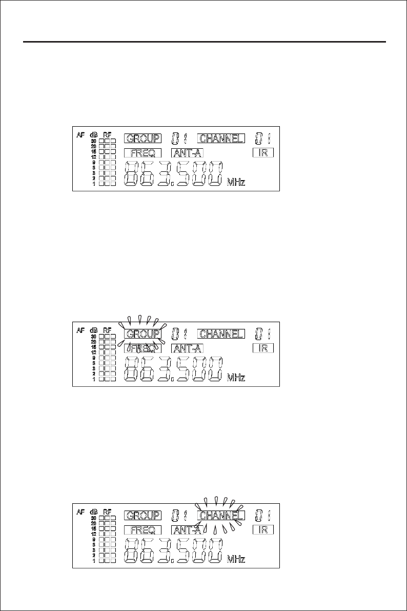
The standard display shows the preselected group, channel, RF power level.
Group
Push the SET button one time, the GROUP blink, Push the up and down buttons to set the
desired group (01-10), Press SET again to confirm.The display will return to standard after a
short period of time of non-activity automatically.
NOTE: Each group 01-10 consists of 10 channels, each corresponding to a specific frequency.
Channel
After the step of setting group, press the SET again, the CHANNEL blink. Push the up and
down buttons to set the desired channel (01-10), Press SET again to confirm. The display
will return to standard after a short period of time of non-activity automatically.
5
System Setup
IR Synch
Note:
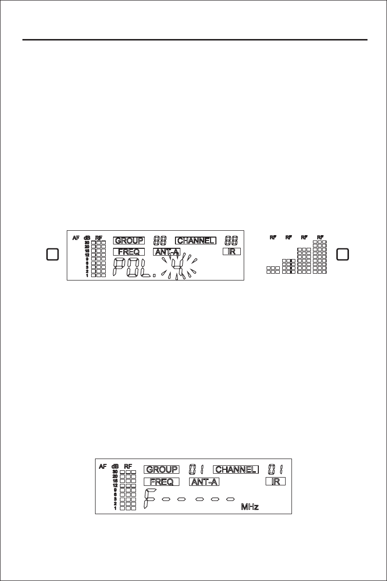
Anytime press the SET button and hold for 1 second, the receiver start to send the infrared
signals (as below picture ), then put the belt-pack receiver’s IR port close to the Transmitter
/Main unit’s IR port , the receiver has to be synchronized to the same frequency (group and
channel) before using.
RF Power
After the step of setting channel, press the SET again, the POL “4” blink ( as below picture1). Push the
up and down buttons to set the desired RF Power level (1-4), Level 1 shows two lines of signals,
the corresponding RF power is 1 mW.
NOTE: The larger RF power, the Longer distance.
Le vel 1 Le vel 2 Le vel 3 Level 4
1 2
The receiver have to be turned off and return-on while transmitter send infrared
signals.After a successful sync, the receiver’s blue LED RF indicator lights up.
6

Receiver (Belt-pack)
Frequency Preparation
Frequency Range
Frequency Type
Transmission Method
Channels
RF Output Power
Oscillation System
Frequency Response
S/N Ratio
T.H.D
Dynamic Range
Operating Temperature
Display
Audio Input
Antenna
Power Supply
Dimensions( L*W*H)
Frequency Preparation
Frequency Range
Transmission Method
Type of reception
Receive Sensitivity
Output
Earphone output
Controls
Indicators
Interface
Antenna
Power Supply
Operating Voltage
Operating time
Dimensions( L*W*H)
Specifications
Transmitter(Main Unit)
PLL Synthesized Control
902.25-926.75 MHz
(Region dependent)
F3E
FM, Mono
100(10x10)
1mW
VCO
60Hz-17KHz+/-3dB
≥105dB
<0.5% at 1KHz
>100dB
-10-+50℃
Backlit LCD (63mm*22mm)
2*6.35mm Jack
1*TNC
DC12V-18V/500mA
210*170*44mm
PLL Synthesized Control
FM, Mono
Diversity
-107dBm (sinad≥30dB)
3.5mm straight pin
3.5mmφ/ 16ohms 105mW
Power ON//OFF, Volume, SET frequency
LED (AF)
Infrared
1/4 wave Length Wire Type
2*AA battery
3V
10h (depending on batteries)
110*63*21mm
7
902.25-926.75 MHz
(Region dependent)

The specification won’t do any further notice for the improvement
Actual product will not be as pictured
NOTE: This equipment has been tested and found to comply with the limits
for a Class B digital device, pursuant to Part 15 of the FCC Rules. These
limits are designed to provide reasonable protection against harmful
interference in a residential installation. This equipment generates,uses
and can radiate radio frequency energy and, if not installed and used in
accordance with the instructions, may cause harmful interference to radio
communications. However, there is no guarantee that interference will not
occur in a particular installation. If this equipment does cause harmful
interference to radio or television reception, which can be determined by
turning the equipment off and on, the user is encouraged to try to correct
the interference by one or more of the following measures:
-- Reorient or relocate the receiving antenna.
-- Increase the separation between the equipment and receiver.
-- Connect the equipment into an outlet on a circuit different from that to
which the receiver is connected.
-- Consult the dealer or an experienced radio/TV technician for help.