HONEYWELL Controls And HVAC Accessories Manual L0712581
User Manual: HONEYWELL HONEYWELL Controls and HVAC Accessories Manual HONEYWELL Controls and HVAC Accessories Owner's Manual, HONEYWELL Controls and HVAC Accessories installation guides
Open the PDF directly: View PDF ![]() .
.
Page Count: 36
Honeywell
THE T8600, T8601, T8602, T8603 CHRONOTHERM III PRO-
GRAMMABLE FUEL SAVER THERMOSTATS PROVIDE
AUTOMATIC CONTROL OF SINGLE STAGE HEATING OR
HEATING/COOLING SYSTEMS AND OFFER USERS THE
HIGHEST STANDARD OF COMFORT AND CONVENIENCE
AVAILABLE WITH ENERGY SAVINGS.
[] T8600 thermostats are powered through the heating/ccoling
system controls; ideal for replacement application.
[] T8601 thermostats are powered direct from transformer,
requiring two wires to system transformer; ideal for new con-
struction installation,
[] T8602 thermostats are powered bythree AA alkaline batter-
ies; suitable for 100 percent control compatibility.
[] T8603 thermostats are powered direct from transformer,
and include additional terminals for one, two or three trans-
former systems.
[] Thermostats include a wiring wallplate.
1-1 Digital clock (liquid crystal display) indicates continuous
time, day, current period, and room temperature. Upon inquiry,
provides program times and program set points.
[1 All thermostats provide 4 different temperature settings per
daily schedule to optimize user comfort and energy savings.
[] Different daily schedules may be selected for weekdays,
Saturday and Sunday.
IJ ENRG. SAV. and SYSTEM light-emitting diodes (LEDs)
included on T8600, T8601, T8603 models.
C3 Models available with automatic heatJcool changeover.
[] Batteries packed with devices provide power to maintain
clock and memory during power failures in T8600, T8601,
T8603 and supply power for operation in T8602.
[] Thermostat can be programmedin hand or after mounted on
wall (batteries must be installed).
E3 Temporary program override available by using--
--WARMER and COOLER keys.
--SKIP next program key.
--CHANGE to last program key.
[] HOLD TEMP key provided for indefinite program override
(vacation_oliday).
[] Adaptive Intelligent Recovery TM function brings room tem-
perature to programmed temperature at programmed time,
maximizing comfort and energy savings.
E3 AdaptiveIntelligent Recovery_tconventional recoveryse~
lection screw includedon backof thermostat.
E3 Fan operation switch included on back of SUPER TRADE-
LINE models to select either independent or direct thermostat
control of fan in heating.
S.M. Form Number 68-0056--1
Rev. 4-90 ©Honeywell Inc. 1990
IMPORTANT
THE SPECIFICATIONS GIVEN IN THIS PUBLICATION DO NOT INCLUDE NORMAL MANUFACTURING TOL-
ERANCES. THEREFORE, THIS UNIT MAY NOT MATCH THE LISTED SPECIFICATIONS EXACTLY. ALSO,
THIS PRODUCT IS TESTED UNDER CLOSELY CONTROLLED CONDITIONS, AND SOME MINOR DIFFER-
ENCES IN PERFORMANCE CAN BE EXPECTED IF THOSE CONDITIONS ARE CHANGED.
SUPER TRADELINE MODELS
SUPER TRADELINE controls offer features on available on TRADELINE models, and are designed to replace a wide
range of Honeywell and competitive controls.
TRADELINE models are selected and packaged to provide ease of stocking, ease of handling, and maximum
replacement value. Specifications of SUPER TRADELINE and TRADELINE controls are the same except as noted below.
THERMOSTAT
MODEL
NUMBER
T8600C a,b
T8602C c
T8603C
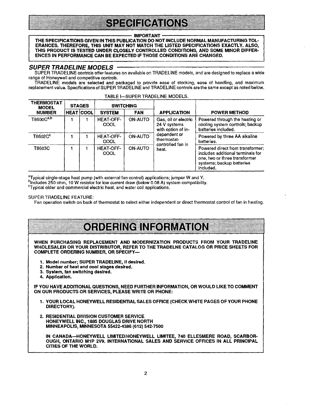
TABLE I---SUPER TRADELINE MODELS.
STAGES
HEAT COOL
1 1
1 1
1 1
SWITCHING
SYSTEM FAN
HEAT-OFF- ON-AUTO
COOL
HEAT-OFF- ON-AUTO
COOL
HEAT-OFF- ON-AUTO
COOL
APPLICATION
Gas, oil or electric
24 Vsystems
with option of in-
dependent or
thermostat-
control(ed fan in
heat.
POWER METHOD
Powered through the heating or
cooling system controls; backup
batteries included.
Powered by three AA alkaline
batteries,
Powered direct from transformer:
includes additional terminals for
one, two or three transformer
systems; backup batteries
included.
aTypical single-stage heat pump (with external fan control) applications; jumper W and Y.
blncludes 250 ohm, 10 W resistor for low current draw (below 0.08 A) system compatibility.
CTypicatolder and commercial electric heat, and water coil applications.
SUPER TRADELINE FEATURE:
Fan operation switch on back of thermostat to select either independent or direct thermostat control of fan in heating.
WHEN PURCHASING REPLACEMENT AND MODERNIZATION PRODUCTS FROM YOUR TRADELINE
WHOLESALER OR YOUR DISTRIBUTOR, REFER TO THE TRADELNE CATALOG OR PRICE SHEETS FOR
COMPLETE ORDERING NUMBER, OR SPECIFY--
1. Model number; SUPER TRADELINE, If desired.
2. Number of heat and cool stages desired.
3. System, fan switching desired.
4. Application.
IF YOU HAVE ADDITIONAL QUESTIONS, NEED FURTHER INFORMATION, OR WOULD LIKE TO COMMENT
ON OUR PRODUCTS OR SERVICES, PLEASE WRITE OR PHONE:
1. YOUR LOCAL HONEYWELL RESIDENTIAL SALES OFFICE (CHECK WHITE PAGES OF YOUR PHONE
DIRECTORY).
2. RESIDENTIAL DIVISION CUSTOMER SERVICE
HONEYWELL INC,, 1885 DOUGLAS DRIVE NORTH
MINNEAPOLIS, MINNESOTA 55422-4386 (612) 542-7500
IN CANADA--HONEYWELL LIMITED/HONEYWELL LIMITEE, 740 ELLESMERE ROAD, SCARBOR-
OUGH, ONTARIO MIP 2V9. INTERNATIONAL SALES AND SERVICE OFFICES IN ALL PRINCIPAL
CITIES OF THE WORLD.
TRADELINE MODELS
TRADELINE models are selected and packaged to provide ease of stocking, ease of handling and maximum
replacement value.
TABLE II--TRADELINE MODELS.
THERMOSTAT
MODEL STAGES
NUMBER HEAT C_0OL
T8600A 1
T8600B a 1 --
T8600B b 1 --
T8600C c1 1
T8600C c'd 1 1
SWITCHING
SYSTEM
HEAT-OFF
HEAT-OFF-COOL
HEAT-OFF-COOL
T8600D e 1 1 HEAT-OFF-
COOL-AUTO
T8601A 1 -- --
T8601B 1-- --
T8601C c 1 1 HEAT-OFF-COOL
T8601D e 1 1 HEAT-OFF-
COOL-AUTO
T8602A 1 -- --
T8602B b 1 -- --
T8602C 1 1 HEAT-OFF-COOL
T8603A 1 --
T8603B 1 -- --
FAN
ON-AUTO
ON-AUTO
ON-AUTO
ON-AUTO
m
ON-AUTO
ON-AUTO
ON-AUTO
ON-AUTO
ON-AUTO
ON-AUTO
aWith positive OFF.
bHeat only with fan control.
CTypical single-stage heat pump (with external fan
control) applications; jumper W and Y.
APPLICATION
Gas, oil or electric 24 V
systems with indepen-
dently controlled fan in
heat.
24 V systems with
thermostat-controlled fan
on heat and cool.
Gas, oil or electric 24V
systems with independ-
ently controlled fan in heat.
Gas, oil or electric
24 V systems with
independently controlled
fan in heat; ideal for new
construction installation.
Gas, oil or electric 24 V
systems with indepen-
dently controlled fan in
heat.
Gas, oil or electric 24 V
systems with indepen-
dently controlled fan in
heat.
POWER METHOD
Powered through
heating or cooling
system controls;
backup batteries
included.
Powered direct from
transformer, requires
two wires to system
transformer; backup
batteries included.
Powered by three AA
alkaline batteries
(included).
Powered from a
separate transformer,
requiring extra wire(s)
to thermostat; backup
batteries included.
dTypical older and commercial electric heat, and water
coil applications.
eln freezing climates, be sure the cooling compressor
has adequate cold start protection.
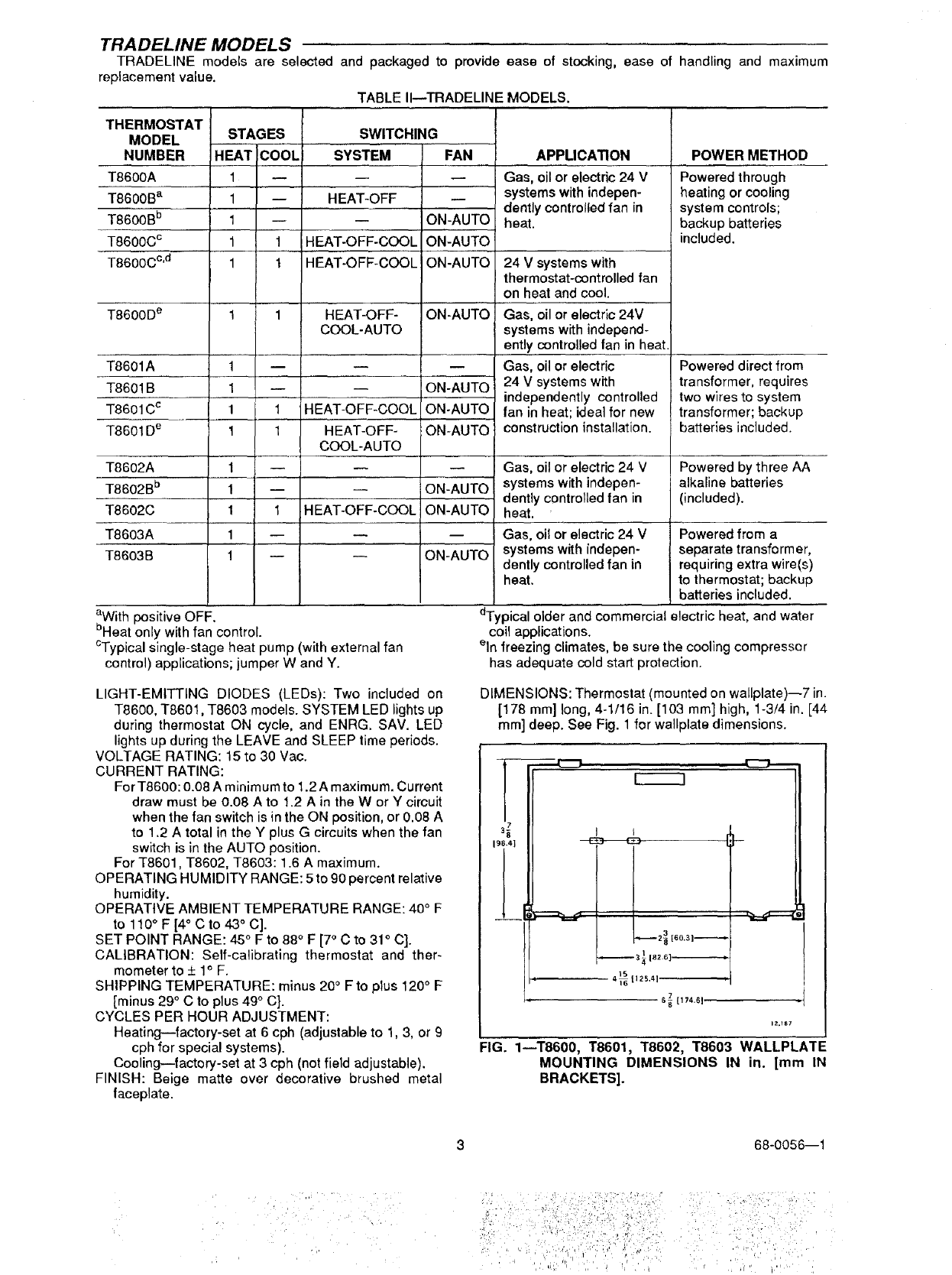
LIGHT-EMITTING DIODES (LEDs): Two included on
T8600, T8601, T8603 models. SYSTEM LED lights up
during thermostat ON cycle, and ENRG. SAV. LED
lights up during the LEAVE and SLEEP time periods.
VOLTAGE RATING: 15 to 30 Vac.
CURRENT RATING:
For T8600:0.08 A minimum to 1.2 A maximum. Current
draw must be 0.08 A to 1.2 A in the W or Y circuit
when the fan switch is in the ON position, or 0.08 A
to 1.2 A total in the Y plus G circuits when the fan
switch is in the AUTO position.
For T8601, T8602, T8603:1.6 A maximum.
OPERATING HUMIDITY RANGE: 5 to 90 percent relative
humidity.
OPERATIVE AMBIENT TEMPERATURE RANGE: 40° F
to 110°F [4" C to 43 ° C].
SET POINT RANGE: 45 ° F to 88°F [7° C to 31 ° C].
CALIBRATION: Self-calibrating thermostat and ther-
mometer to + 1° F.
SHIPPING TEMPERATURE: minus 20° Fto plus 120°F
[minus 29 ° C to plus 49° C].
CYCLES PER HOUR ADJUSTMENT:
Heating--factory-set at 6 cph (adjustable to 1, 3, or 9
cph for special systems).
Cooling--factory-set at 3 cph (not field adjustable).
FINISH: Beige matte over decorative brushed metal
faceplate.
DIMENSIONS: Thermostat (mounted on wallplate)--7 in.
[178 mm] long, 4-1/16 in. [103 mm] high, 1-3/4 in. [44
mm] deep. See Fig. 1 for wallplate dimensions.
IZ._S7
FIG. 1--T8600, T8601, T8602, T8603 WALLPLATE
MOUNTING DIMENSIONS IN in. [mm IN
BRACKETS].
68-0056--1
/• !iiiiii i! i !ii! Iiili
i i!iii; ! i
i ¸.... !i,i
ACCESSORIES:
193121A Cover Plate Assembly includes cover plate,
adapter ring and screws. Covers marks left by old
thermostat. Allows mounting on vertical or horizontal
outlet box. 6-9/10 in. x 4-3/4 in. [175 mm x 121 mm].
TG586A Locking Cover.
202384B Resistor for T8600.
REPLACEMENT PART:
220529A Replacement Door Assembly.
:.Jj ii!!i:i !i)i i i!i ii! i!!i
COMPATIBILITY
The T8600 Thermostats will replace most heating or
heating/cooling system thermostats, and are designed to
be part of a Honeywell control system. They can be used
with other control systems, but an isolating relay may be
needed in the thermostat control circuit. See Table II1.
IMPORTANT
If your system needs an isolating relay and one is not
installed, no hazard will exist, but the system will not
operate. The thermostat will not be damaged unless
you connect it directly to 120 Vac.
If the current draw of the primary control is below O.08A,
a 202394B Resistor should be installed on the furnace
terminal strip to increase the current draw of the primary
control to 0.08A or greater. This would alleviate any
compatibility problem between the T8600 Thermostat and
the system due to alow current draw. For installation
details, refer to instructions packed with the resistor.
The T8601, T8602 and T8603 Thermostats are com-
patible with other control systems without the need for an
isolating relay.
WHEN INSTALLING THIS PRODUCT...
1. Read these instructions carefully. Failure to follow
them could damage the product or cause a hazardous
condition.
2. Checkthe ratings given on the product to make sure
the product is suitable for your application.
3. Installer must be a trained, experienced service
technician.
4. Allow thermostat to warm to room temperature be-
fore programming.
5. After installation is complete, check out product
operation as provided in these instructions.
Disconnect power supply to prevent electrical shock
or equipment damage.
LOCATION
Install thermostat and wallplate about 5 ft. [1.5 m] above
the floor in an area with good air circulation at room
temperature.
Do not install the thermostat where it may be affected
by-
- drafts or dead spots behind doors, in corners or
under cabinets.
-- hot or cold air from ducts.
-- radiant heat from sun or appliances.
-- concealed pipes and chimneys.
-- unheated (uncooled) areas behind the thermostat,
such as an outside wall.
If Replacing An Existing Thermostat
Turn thermostat power off at furnace or boiler. Amul-
tiple transformer system may require turning off multiple
switches or disconnects. Remove any existing wallplate or
subbase from wall. Label each wire with, or write down, the
letter or number on the wiring terminal as the wire is
removed, to avoid miswiring later.
If New Installation
Run cable to ahole at the selected wall location, and pull
about 3in. [76 mini of wire through the opening. Color-
coded 18 gauge thermostat cable with at least one conduc-
tor for each wiring terminal is recommended. Good service
practice recommends selection of cable with one or two
more conductors than the immediate application requires.
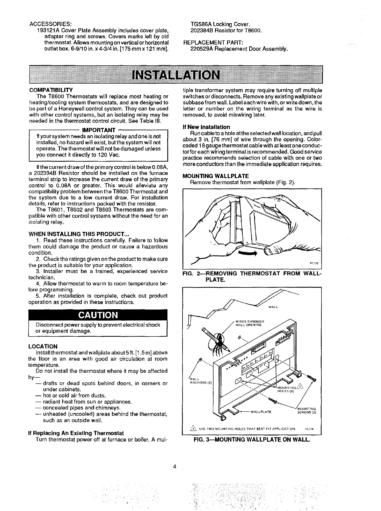
MOUNTING WALLPLATE
Remove thermostat from wallplate (Fig. 2).
1_,179
FIG. 2NREMOVING THERMOSTAT FROM WALL-
PLATE.
WALL
ANCHORS (2)
/,_J_ USE TWO MOUNTING HOLES THAT BEST FIT APPLICATION, 12,134
FIG. 3--MOUNTING WALLPLATE ON WALL.
•;i i,, _' ' _:i,
!
:;i ] i: i/i iiiiiiiii :: ): ":!:?21
_' ' '' , 'l ', i; ¸ , ,'
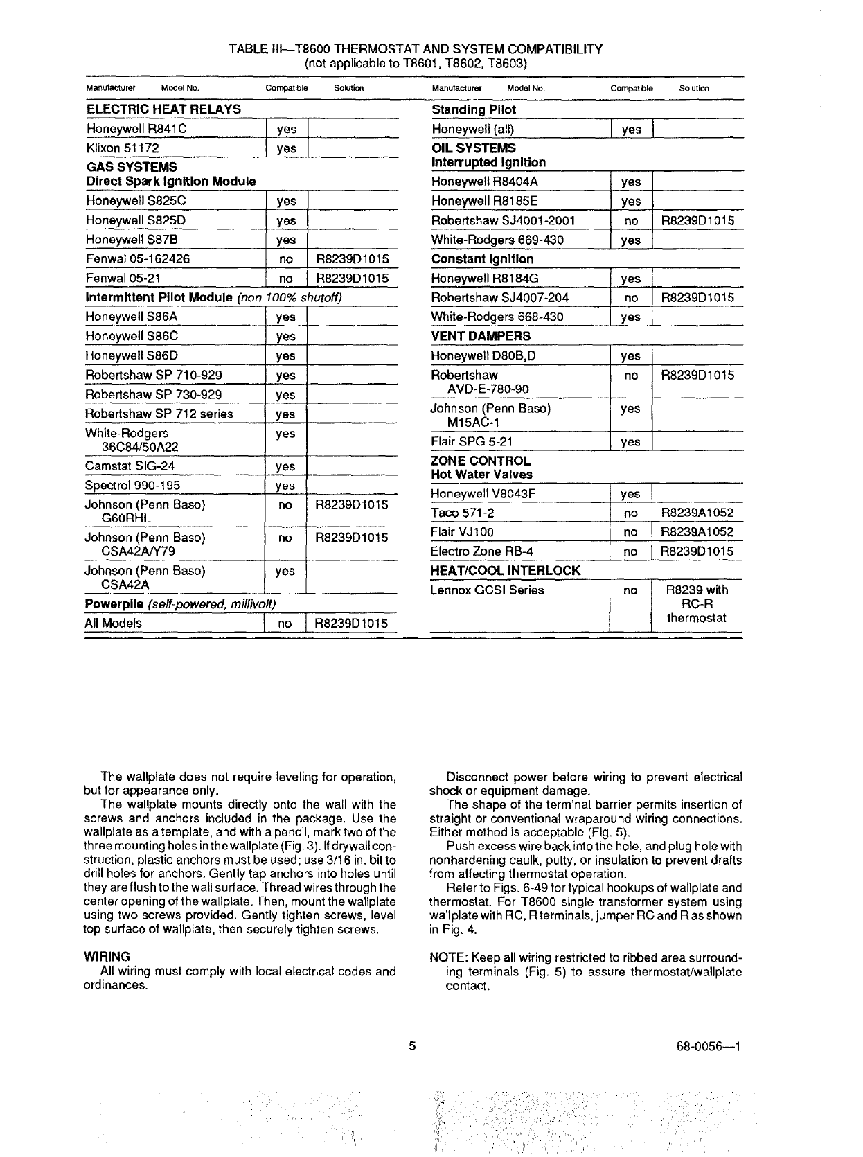
TABLE III--T8600 THERMOSTAT AND SYSTEM COMPATIBILITY
(not applicable to T8601, T8602, T8603)
Manufacturer Model No. Compatible Solution1
ELECTRIC HEAT RELAYS
Honeywell R841C
Klixon 51172
GAS SYSTEMS
Direct Spark Ignition Module
Honeywell $825C
Honeywell $825D
Honeywell $87B
Fenwa105-162426
Fenwa105-21
Intermittent Pilot Module (non
Honeywell $86A
Honeywell $86C
Honeywell $86D
Robertshaw SP 710-929
Rebertshaw SP 730-929
Robertshaw SP 712 series
White-Rodgers
36C84/50A22
Camstat SIG-24
Spect rol 990-195
Johnson (Penn Base)
G6ORHL
Johnson (Penn Base)
CSA42A/Y79
Johnson (Penn Base)
CSA42A
yes
yes
yes
yes l
lyes I
!: ° I R8239D1015
R8239D1015
100% shutoff)
yes
yes
ye s
yes
yes
yes
yes
yes
yes
no
rio
yes
R8239D1015
R8239D1015
Powerplle (self-powered, millivolt)
All Models I no ]R8239D1015
Manufacturer Model No.
Standing Pilot
Honeywell (all)
OIL SYSTEMS
Interrupted Ignition
Honeywell R8404A
Honeywell R8185E
Robertshaw SJ4001-2001
White-Rodgers 669-430
Constant Ignition
Honeywell R8184G
Robertshaw SJ4007-204
White-Rodgers 668-430
VENT DAMPERS
Honeywell D80B,D
Robertshaw
AVD-E-780-90
Johnson (Penn Base)
M15AC-1
Flair SPG 5-21
ZONE CONTROL
Hot Water Valves
Honeywell V8043F
Taco 571-2
Flair VJ100
Electro Zone RB-4
HEAT/COOL INTERLOCK
Lennox GCSI Series
CornDatble Solution
lyosl
yes
lYesI
IR823°o1°1
I yes
yneO R8239D1015
yes I
no I R8239D1015
! yes I
i
yes I
ii s R8239A1052
no R8239A1052
R8239D1015
no ]R8239with
IRC-R
thermostat
The wallplate does not require leveling for operation,
but for appearance only.
The wallplate mounts directly onto the wall with the
screws and anchors included in the package. Use the
wallplate as a template, and with a pencil, mark two of the
three mounting holes inthe wallplate (Fig. 3). Ifdrywall con-
struction, plastic anchors must be used; use 3/16 in. bit to
drill holes for anchors. Gently tap anchors into holes until
they are flush to the wall surface. Thread wires through the
center opening of the wallplate. Then, mount the wallplate
using two screws provided. Gently tighten screws, level
top surface of wallplate, then securely tighten screws.
WIRING
All wiring must comply with local electrical codes and
ordinances.
Disconnect power before wiring to prevent electrical
shock or equipment damage.
The shape of the terminal barrier permits insertion of
straight or conventional wraparound wiring connections.
Either method is acceptable (Fig. 5).
Push excess wire back into the hole, and plug hole with
nonhardening caulk, putty, or insulation to prevent drafts
from affecting thermostat operation.
Refer to Figs. 6-49 for typical hookups of wallplate and
thermostat. For T8600 single transformer system using
wallplate with RC, R terminals, jumper RC and R as shown
in Fig. 4.
NOTE: Keep all wiring restricted to ribbed area surround-
ing terminals (Fig. 5) to assure thermostat/wallplate
contact.
68-0056--1
il rli!iiiiiiiilliii i!iiili i :i/
_1_ _ ,, _, , r ',., 4 _ _ _,
ooooe®ooo _oo0ooo
o
-I0
Iz.132_-
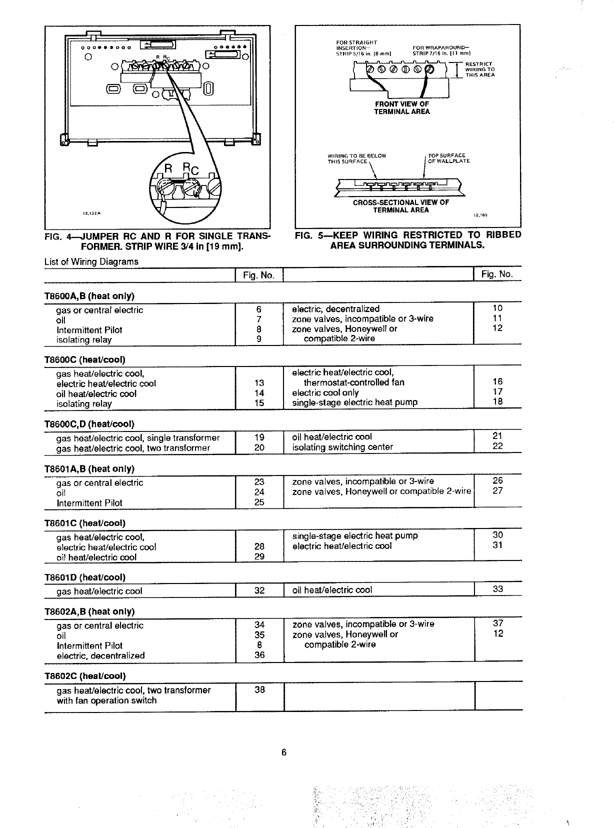
FIG. 4--JUMPER RC AND R FOR SINGLE TRANS-
FORMER. STRIP WIRE 3/4 in [19 mm].
List of Wiring Diagrams
IFig. No.
T8600A, B (heat only)
gas or central electric
oil
Intermittent Pilot
isolating relay
FOR STRAIGHT
INSERTION FOR WRAPAROUND--
STRIP 5/16 in, [8 mint STRIP 7/16 in. II 1 mmJ
__ RESTRICT
WIRING 1"O
THIS AREA
FRONT VIEW OF
TERMINAL AREA
CROSS-SECTIONAL VIEW OF
TERMINAL AREA _2,t6_
FIG. 5mKEEP WIRING RESTRICTED TO RIBBED
AREA SURROUNDING TERMINALS.
I6Ielectric, decentralized
7 zone valves, incompatible or 3-wire
8 zone valves, Honeywell or
9 compatible 2-wire
T8600C (heat!cool)
gas heat/electric cool, I
electric heat/electric cool I 13
oil heat/electric cool 14
isolating relay 15
T8600C, D (heat/cool)
gas heat/electric cool, single transformer I19
gas heat/electric cool, two transformer I20
T8601A,B (heat only)
gas or central electric
oil
Intermittent Pilot
I electric heat/electric cool,
thermostat-controlled fan
electric cool only
single-stage electric heat pump
1"8601C (heat/cool)
gas heat/electric cool,
electric heat/electric cool
oil heat/electric cool
Ioil heat/electric cool
isolating switching center
T8601D (heat/cool)
gas heat/electric cool
T8602A,B (heat only)
gas or central electric
oil
Intermittent Pilot
electric, decentralized
I23 Izone valves, incompatible or 3-wire
24 Izone valves, Honeywell or compatible 2-wire25
T86020 (heat/cool)
gas heat/electric cool, two transformer
with fan operation switch
IFig. No.
I 28
29
10
11
12
I32
I16
17
18
I4
35
8
36
I2122
I38
26
27
Iingle-stage electric heat pump
electric heat/electric cool
30
31
I oil heat/electric cool I33
Ione valves, incompatible or 3-wire
zone valves, Honeywell or
compatible 2-wire I37
12
II
List of Diagrams (continued)
T8602C (heat/cool)
gas heat/electric cool, two transformer
gas heatlelectric cool,
electric heat/electric cool
T8603A,B (heat only)
gas
oil
Intermittent Pilot
T8603C (heat/cool)
gas heat/electric cool,
electric heat/electric cool
oil heat/electric cool
I Fig. No.
I 39
40
I 42
43
44
I 7
48
I oil heat/electric cool
I one valves, incompatible or 3-wire
zone valves, Honeywell or
compatible 2-wire
electric heat/electric cool,
gas heat/electric cool,
thermostat-controlled fan
I Fig.No.
HEATING-ONLY WALLPLATE
GAS VALVE
OR HEAT
A
L2 .---,qJJ 24V
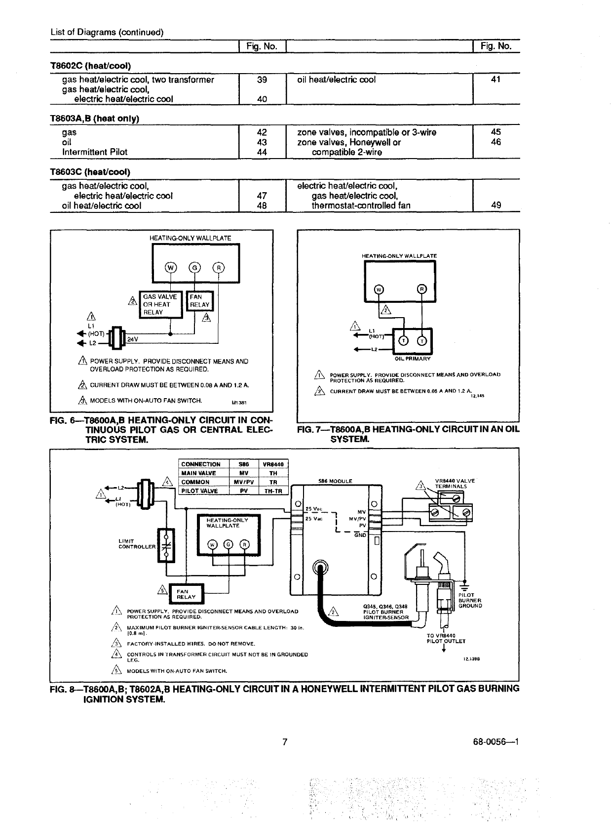
APOWER SUPPLY. PROVIDE DISCONNECT MEANS AND
OVERLOAD PROTECTION AS REQUIRED.
Z_ CURRENT DRAW MUST BE BETWEEN 0,08 A AND t.2 A.
MODELS WITH ON-AUTO FAN SWITCH. M1381
FIG. 6--T8600A,B HEATING-ONLY CIRCUIT IN CON-
TINUOUS PILOT GAS OR CENTRAL ELEC-
TRIC SYSTEM.
HEATING-ONLY WALLPLATE
OIL PRIMARY
/_ POWER SUPPLY. PROVIDE DISCONNECT MEANS AND OVERLOAD
PROTECTION AS REQUIRED+
CURRENT DRAW MUST BE BETWEEN 0.08 A AND 1.2 A. t2,14S
FIG. 7--T8600A, B HEATING-ONLY CIRCUIT IN AN OIL
SYSTEM.
CONNECTION SE6 VR8440
MAIN VALVE V R8440 VALVE
COMMON $86 MODULE I _/_ "_*. TERMINALS
PILOT VALVE _ __
025 Vac
WALLPLATE L- G"--N6_
LIMIT
CONTROLLER
°
A
L_ POWER SUPPLY. PROVIDE DISCONNECT MEANS AND OVERLOAD _I_
PROTECTION AS REQUIRED.
MAXIMUM PILOT BURNER IGNITER-SENSOR CABLE LENGTH: 30 In.
t0.8 m]. TO VR8440
L/_ FACTORY-INSTALLED WIRES. DO NOT REMOVE, PILOT OUTLET
_j CONTROLS IN TRANSFORMER CIRCUIT MUST NOT BE IN GROUNDED
LEG, 12,_398
MODELS WITH OH-AUTO FAN SWITCH.
FIG. 8--T8600A, B; T8602A,B HEATING-ONLY CIRCUIT IN A HONEYWELL INTERMI'FrENT PILOT GAS BURNING
IGNITION SYSTEM.
68-0056--1
iii: i ii :ii¸i¸¸i:¸i¸¸¸ '
=
,,i r i
HEATING-ONLY WALLPLATE
R8239D1015
®
®
SYSTEM
TRANSFORMER
RED
_24 V
PRIMARY
EONTROL
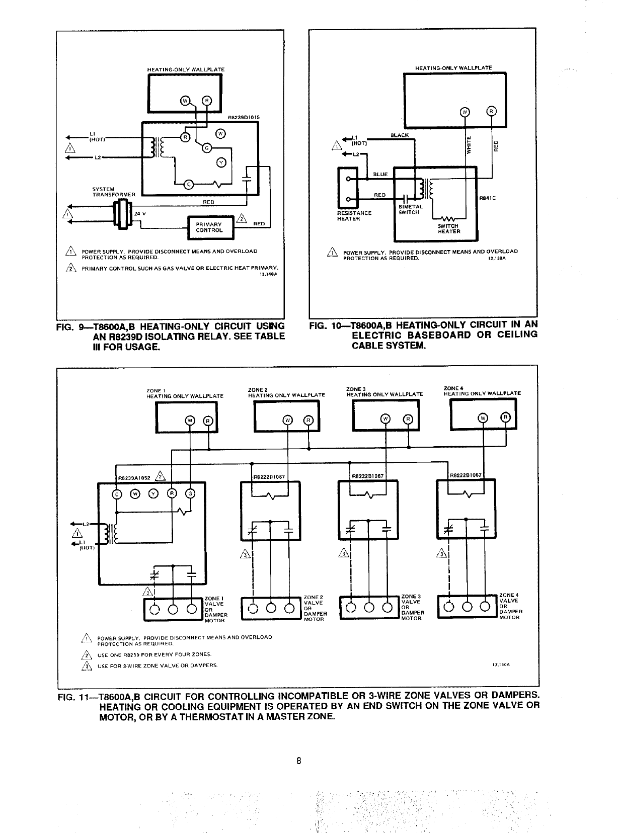
,_ POWER SUPPLY• PROVIDE DISCONNECT MEANS AND OVERLOAD
PROTECTION AS REQUIRED.
/_ PRIMARY CONTROL SUCH AS GAS VALVE OR ELECTRIC HEAT PRIMARY.
t2,146A
FIG. 9--T8600A,B HEATING-ONLY CIRCUIT USING
AN R8239D ISOLATING RELAY. SEE TABLE
III FOR USAGE.
HEATING-ONLY WALLPLATE
BLA
RESISTANCE _C
HEATER
Z_ POWER SUPPLY. PROVIDE DISCONNECT MEANS AND OVERLOAD
PROTECTION AS REQUIRED. 12,138A
=IG. 10--T8600A,B HEATING-ONLY CIRCUIT IN AN
ELECTRIC BASEBOARD OR CEILING
CABLE SYSTEM.
ZONE IZONE 2 ZONE 3 ZONE 4
HEATING ONLY WALLPLATE HEATING ONLY WALLPLATE HEATING ONLY WALLPLATE HEATING ONLY WALLPLATE
RB239A1052
®®
#!
I
_POWER SUPPLY. PROVIDE DISCONNECT MEANS AND OVERLOAD
PROTECTION AS REQUIRED¸
USE ONE R8239 FOR EVERY FOUR ZONES¸
USE FOR 3_WIRE ZONE VALVE OR DAMPERS¸
zonE2 Iz°NE
VALVE VALVE
OR ) ( _,.PER
DAMPER
MOTOR MOTOR
I
I
I
I
FIG. 11--T8600A,B CIRCUIT FOR CONTROLLING INCOMPATIBLE OR 3-WIRE ZONE VALVES OR DAMPERS.
HEATING OR COOLING EQUIPMENT IS OPERATED BY AN END SWITCH ON THE ZONE VALVE OR
MOTOR, OR BY A THERMOSTAT IN A MASTER ZONE.
:,,_:/,i_:__,_i_ ' ', _ qi,_ _
j!_, ,:::, _ ,.,,i__,_ :_..... _/,
ZONE 1ZONE 2 ZONE 3 ZONE 4
HEATING-ONLY HEATING-ONLY NEATING.ONLY HEATING-ONLY
WALLPLATE WALLPLATE WALLPLATE WALLPLATE
' l
ZONE 1 ZONE 2ZONE 3 ZONE 4
VALVE OR VALVE OR VALVE OR VALVE OR
DAMPER MOTOR DAMPER MOTOR DAMPER MOTOR DAMPER MOTOR
._ POWER SUPPLY. PROVIDE DISCONNECT MEANS AND OVERLOAD
PROTECTION AS REQUIRED.
L_ USE ONE 38 VA TRANSFORMER FOR EVEnY FOUR ZONES
(HONEYWELL AT72D OR EQUIVALENT). M1376
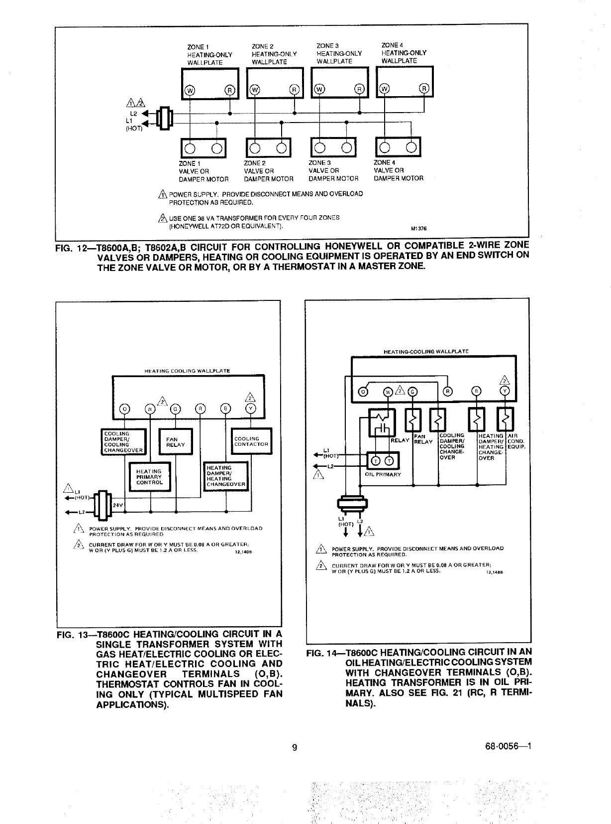
FIG. 12mT8600A,B; T8602A,B CIRCUIT FOR CONTROLLING HONEYWELL OR COMPATIBLE 2-WIRE ZONF
VALVES OR DAMPERS, HEATING OR COOLING EQUIPMENT IS OPERATED BY AN END SWITCH ON
THE ZONE VALVE OR MOTOR, OR BY A THERMOSTAT IN A MASTER ZONE.
HEATING COOLING WALLPLATE
A
CO L!G
DAMPEN/ FAI
COOLING
CHANGEOVER
HEATING
DAMPE_
HEATING
CHANGEOVER
_POWER SUPPLY PROVIDE DISCONNECT MEANS AND OVERLOAD
PROTECTION AS REG_LJIRED
/_, CURRENT DRAW FOR W OH Y MUST IBE 0_(18 A OR GREATER;
WOR (Y PLUS G) MUST BE 1.2 A OR LESS¸ tz,l_
FIG. 13--T8600C HEATING/COOLING CIRCUIT IN A
SINGLE TRANSFORMER SYSTEM WITH
GAS HEAT/ELECTRIC COOLING OR ELEC-
TRIC HEAT/ELECTRIC COOLING AND
CHANGEOVER TERMINALS (O,B).
THERMOSTAT CONTROLS FAN IN COOL-
ING ONLY (TYPICAL MULTISPEED FAN
APPLICATIONS).
HEATING-COOLING WALLPLATE
L1
A
LI
_ DISCONNECT MEANS AND OVERLOAD
POWER SUPPLY. PROVIDE
PROTECTION AS REQUIRED.
CURRENT DRAW FOR W OR YMUST BE 0.08 AOR GREATER;
WOR (Y PLUS G) MUST BE 1.2 A OR LESS. 12,148 B
FIG. 14_T8600C HEATING/COOLING CIRCUIT IN AN
OIL HEATING/ELECTRIC COOLING SYSTEM
WITH CHANGEOVER TERMINALS (O,B).
HEATING TRANSFORMER IS IN OIL PRI-
MARY. ALSO SEE RG. 21 (RC, R TERMI-
NALS).
68-0056--1
ii_: i ¸ i :!:!_:i ::,-ii_/¸::¸'I¸¸_:i_ • • ' ¸¸¸¸ '¸:
HEATING-COOLING WALLPLATE
AIR
COND,
EQUIP.
t.2
!
POWER SUPPLY, PROVIDE DISCONNECT MEANS AND OVERLOAD
PROTECTION AS REQUIRED.
A//_ PRIMARY CONTROL, SUCH AS GAS VALVE OR ELECTRONIC
IGNITION MODULE.
Z_ CURRENT DRAW FOR W OR Y MUST BE 0.08 A OR GREATER;
WOR (Y PLUS G) MUST BE 1.2 A OR LESS. 12_149B
HEATING-COOLING WALLPLATE
_POWER SUPPLY. PROVIDE DISCONNECT MEANS AND
OVERLOAD PROTECTION AS REQUIRED.
Zt2'kSYSTEM SWITCH MUST BE IN COOL POSITION TO
PREVENT DRAIN ON BATTERIES.
Z_,ON COOLING-ONLY APPLICATION, EQUIPMENT MUST
BE POWERED YEAR-ROUND.
CURRENT DRAW FOR Y MUST BE 0.08 A OR GREATER;
Y PLUS G MUST BE LESS THAN 1,2 A. M2079B
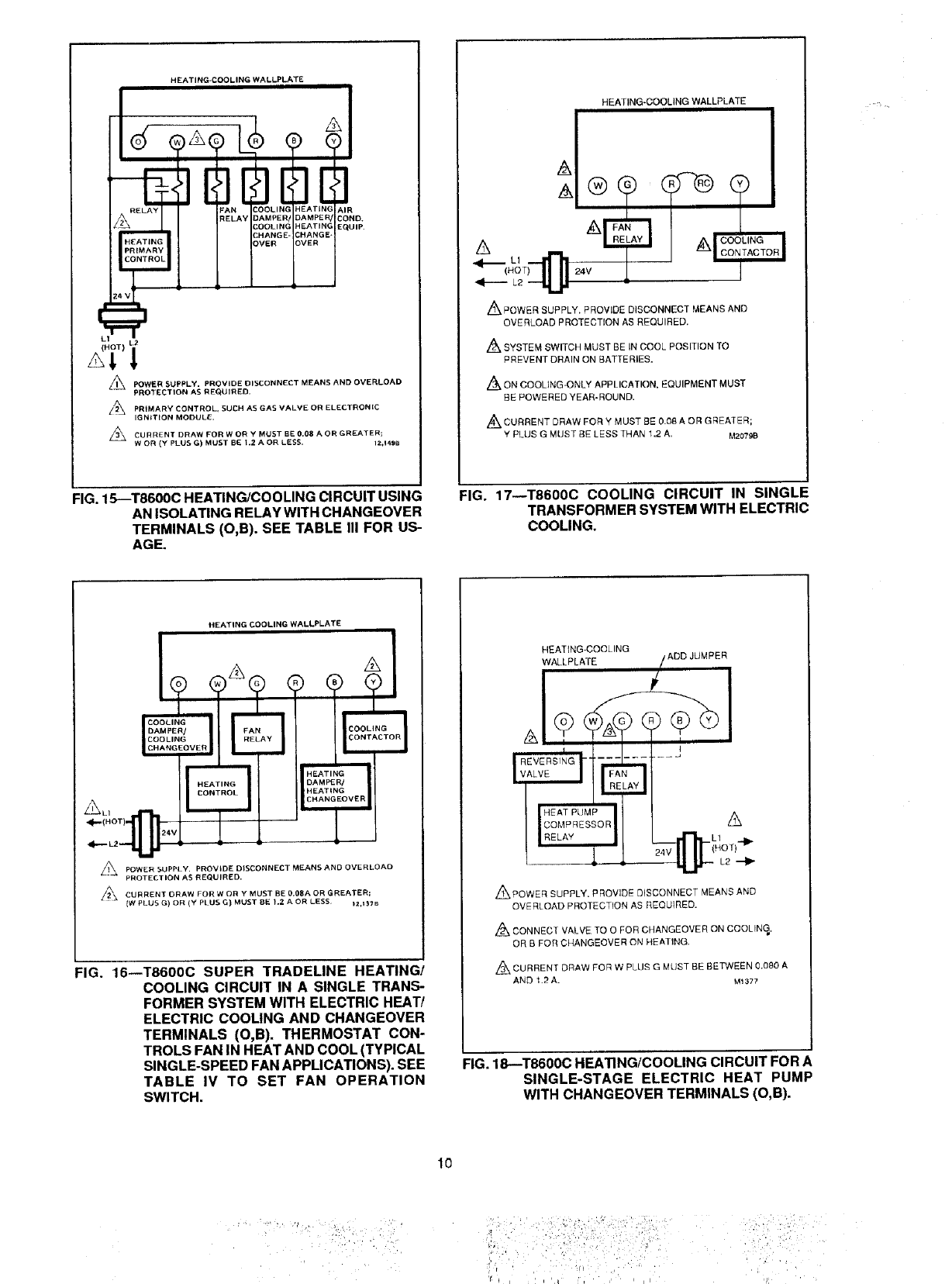
FIG. 15--T8600C HEATING/COOLING CIRCUIT USING
AN ISOLATING RELAY WITH CHANGEOVER
TERMINALS (O,B). SEE TABLE III FOR US-
AGE.
FIG. 17--T8600C COOLING CIRCUIT IN SINGLE
TRANSFORMER SYSTEM WITH ELECTRIC
COOLING.
HEATING COOLING WALLPLATE
COOLING AY_
DAMPER/
COOLING
CHANGEOVER
"--1 HEAT,NG"
DAMPER/
HEATING
CHANGEOVER
_24V
/_ DISCONNECT MEANS AND OVERLOADPOWER SUPPLY, PROVIDE
PROTECTION AS REQUIRED,
CURRENT DRAW FOR W OR Y MUST BE 0.08A OR GREATER;
{W PLUS G) OR (Y Pt US G) MUST BE 1.2 AOR LESS )2,I37B
:IG. 16--T8600C SUPER TRADELINE HEATING/
COOLING CIRCUIT IN A SINGLE TRANS-
FORMER SYSTEM WITH ELECTRIC HEAT/
ELECTRIC COOLING AND CHANGEOVER
TERMINALS (O,B). THERMOSTAT CON-
TROLS FAN IN HEAT AND COOL (TYPICAL
SINGLE-SPEED FAN APPLICATIONS). SEE
TABLE IV TO SET FAN OPERATION
SWITCH.
HEATING-COOLING ADD JUMPER
WALLPLATE
,&
-(L10 T)'41_
L2
,,_POWER SUPPLY. PROVIDE DISCONNECT MEANS AND
OVERLOAD PROTECTION AS REQUIRED.
Z_ CONNECT VALVE TO 0 FOR CHANGEOVER ON COOLING,
OR B FOR CHANGEOVER ON HEATING.
Z_ CURRENT DRAW FOR W PLUg G MUST BE BETWEEN 0.080 A
AND 1.2 A. M1377
FIG. 18--T8600C HEATING/COOLING CIRCUIT FOR A
SINGLE-STAGE ELECTRIC HEAT PUMP
WITH CHANGEOVER TERMINALS (O,B).
10
;:i_I,',: : iii
'_ _ = i i '_t¸ i'i _ i I I dl
HEATING-COOLINGWALLPLATE
p..
/1\ POWER SUPPLY. PROVIDE DISCONNECT MEANS AND
OVERLOAD PROTECTION AS REQUIRED,
PRIMARY CONTROL, ._UCN AS GAS VALVE OR ELECTRONIC
IGNITION MODULE.
CURRENT DRAW FOR W OR Y PLUS G MUST 8E BETWEEN 0,08 A
AND 1.2 A.
Z/_ ON TB60OD, HEATING SYSTEM POWER MUST BE ON YEAR-ROUND.
M1382
HEATING-COOLING WALLPLATE
&A
L1
FAN
RELAY AIR
COND.
EQUIP.
_1_ POWER SUPPLY, PROVIDE DISCONNECT MEANS AND
OVERLOAD PROTECTION AS REQUIRED,
CURRENT DRAW FOR W OR YPLUS G MUST BE BE]BNEEN 0.08 A
AND 1,2 A,
Z_ ON T860OD, HEATING SYSTEM POWER MUST BE ON YEAR-ROUND.
M1380
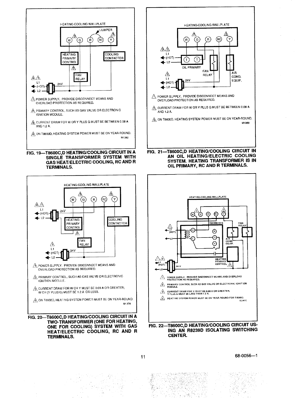
FIG. 19--T8600C, D HEATING/COOLING CIRCUITIN A
SINGLE TRANSFORMER SYSTEM WITH
GAS HEAWELECTRIC COOLING, RCAND R
TERMINALS.
FIG. 21mT8600C, D HEATINGICOOLING CIRCUIT IN
AN OIL HEATING/ELECTRIC COOLING
SYSTEM. HEATING TRANSFORMER IS IN
OIL PRIMARY, RC AND R TERMINALS.
HEATING-COOLING WALLPLATE
L1
_1_ POWER SUPPLY• PROVIDE DISCONNECT MEANS AND
OVERLOAD PROTECTION AS REQUIRED
PRIMARY CONTROL, SUCH AS GAS VALVE OR ELECTRONIC
IGNITION MODUL E.
,_\ CURRENT DRAW FOR W OR Y MUST BE 0.08 A OR GREATER;
W OR (Y PLUS G) MUST BE 1,2 A OR LESS.
._ON SYSTEM POWER MUST BE ON YEAR-ROUND,
T6600D, HEATING
M1378
FIG. 20_T8600C, D HEATING/COOLING CIRCUIT IN A
TWO-TRANSFORMER (ONE FOR HEATING,
ONE FOR COOLING) SYSTEM WITH GAS
HEAT/ELECTRIC COOLING, RC AND R
TERMINALS.
HEATING-COOLING WALL.PLATE
POWER SUPPLY. PROVIIDE OISCONNECT MEANS AND OVERLOAD
PROTECTION AS RE_tJlREO.
Z_ PRIMARY CONTROL SUCH AS GAS VALVE OR ELECTRONIC IGNIT_OR
MODULE,
CURRENT DRAW FOR Y MUST BE O.O8 AOR G REATER_
YPLUS G MUST BE LESS THAN t .2 A.
L_ HEATING SYSTEM POWER MUST BE ON YEAI_ROUND FOR T8600D
FIG. 22--T8600C, D HEATING/COOLING CIRCUIT US-
ING AN R8239D ISOLATING SWITCHING
CENTER.
11 68-0056--1
, G ¸ :•
i
HEATING-ONLY WALLPLATE
1÷ ÷91
POWER SUPPLY• PROVIDE DISCONNECT MEANS AND OVERLOAD
PROTECTION AS REQUIRED.
24 Mac TRANSFORMER SLJPPLIEB THERMOSTAT POWER, IF ONE
ADDITIONAL WIRE {C) CANNOT BE BROUGHT TO THERMOSTAT
LOCATION, USE T8600A OR B.
=//_\ FOR MODELS WITH ON AUTO FAN SWITCH. 12,155B
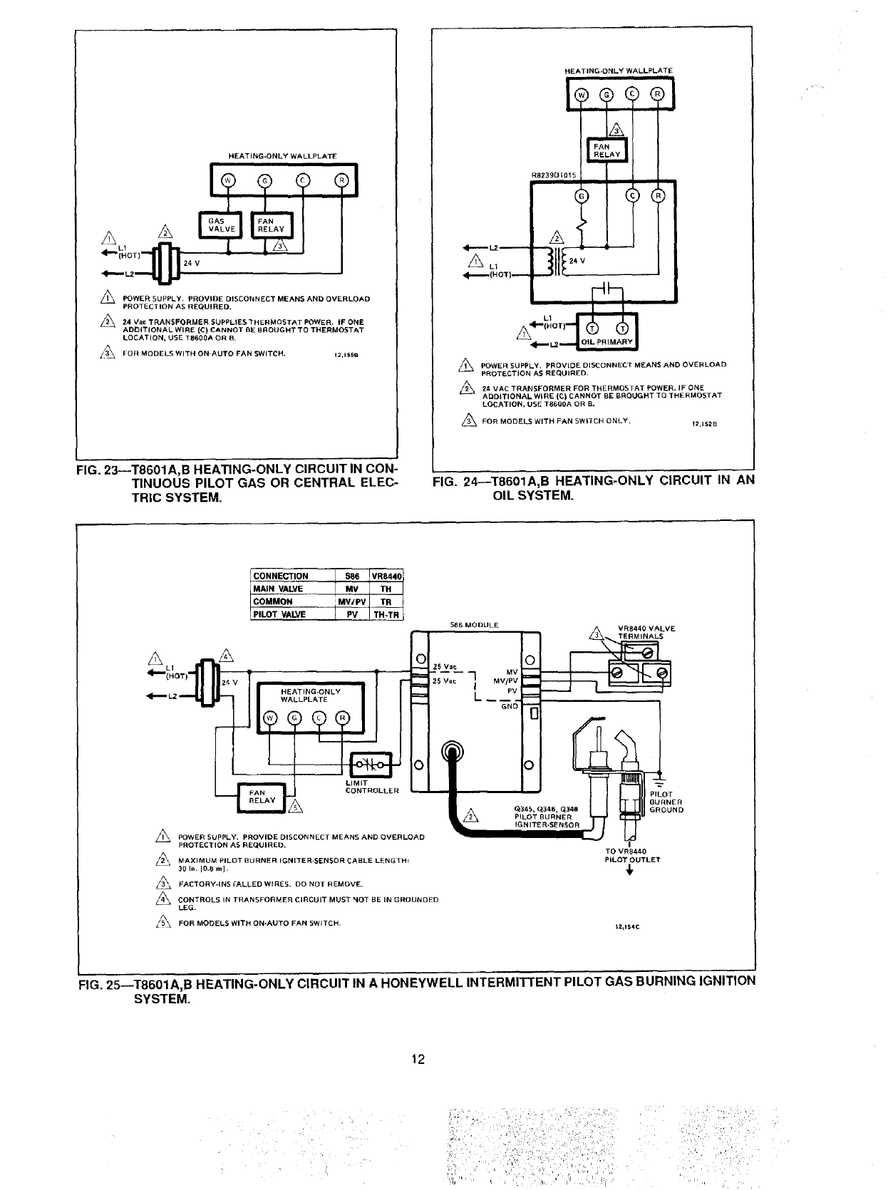
FIG. 23--T8601A,B HEATING-ONLY CIRCUIT IN CON-
TINUOUS PILOT GAS OR CENTRAL ELEC-
TRIC SYSTEM.
HEATING-ONLY WALLPLATE
R8239DIO15
L1
POWER SUPPLY. PROVIDE DISCONNECT MEANS AND OVERLOAD
PROTECTION AS REQUIRED.
_._ 24 VAC TRANSFORMER FOR THERMOSTAT POWER. IF ONE
ADDITIONAL WIRE (C) CANNOT BE BROUGHT TO THERMOSTAT
LOCATION, USE T6600A OR B_
FOR MODELS WITH FAN SWITCH ONLY. _2,1_2B
FIG. 24--T8601A,B HEATING-ONLY CIRCUIT IN AN
OIL SYSTEM.
A A
CONNECTION $86 VR844C
MAIN VALVE MV TH
COMMON MV/PV TR
]
PILOT VALVE IPV TH-TR
$88 MODULE
O25 Vat
MV/PV
L PV
GNO
CONTROLLER
A[A
POWER SUPPLY. PROVIDE DISCONNECT MEANS AND OVERLOAD
PROTECTION AS REQUIRED.
/_ MAXIMUM PILOT BURNER IGNITER-SENSOR CABLE LENGTH:
30 in. IO.B m I .
FACTORY-INS rALLED WIRES, DO NOT REMOVE.
CONTROLS IN TRANSFORMER CIRCUIT MUST _OT BE IN GROUNDED
LEG.
Li_ FOR MObELS WITH ON-AUTO FAN SWITCH.
__VE
\
-d
TO VR84/_0
PILOT OUTLET
t2,154C
FIG. 25_T8601A,B HEATING-ONLY CIRCUIT IN A HONEYWELL INTERMITTENT PILOT GAS BURNING IGNITION
SYSTEM.
12
• iiii!iii i il !;ill iii!il:
• _i_/iii ii_!:i=i!_¸:I,i_ii_iiii•_i_i!ii_:iil)i;;
ZONE 1
HEATING-ONLY WALLPLATE
R8239A1052_
®®(
#
ZONE 2
HEATING_ONLY WALLPLATE
iZONE €
HEATING-ONLY WALLPLATE
_, POWER SUPPLY. PROVIDE DISCONNECT MEANS AND OVERLOAD
PROTECTION AS RECURRED.
USE ONE RB239 FOR EVERY FOUR ZONES,
,_ USE FOR 3-WIRE ZONE VALVE OR DAMPERS.
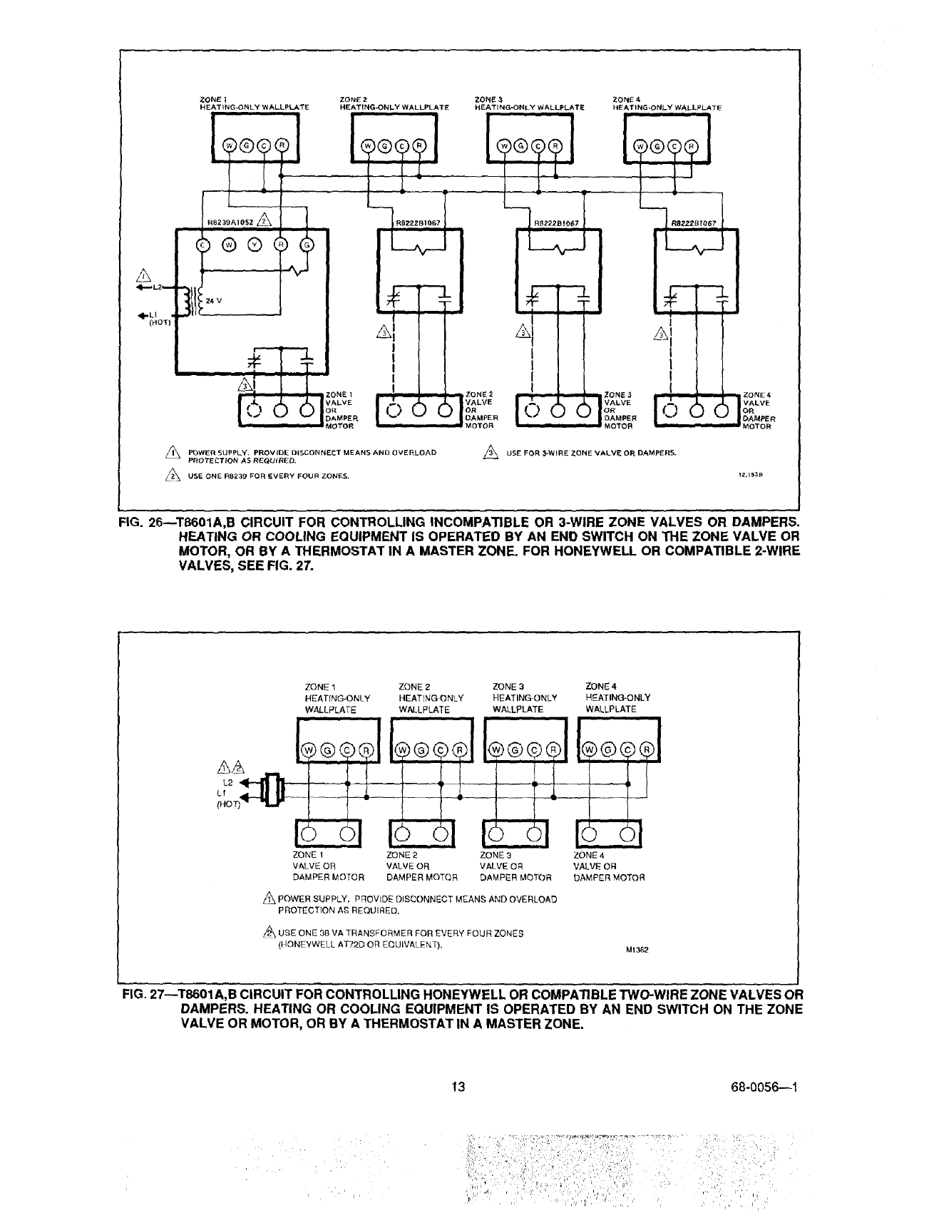
FIG. 26--TB601A,B CIRCUIT FOR CONTROLLING INCOMPATIBLE OR 3-WIRE ZONE VALVES OR DAMPERS.
HEATING OR COOLING EQUIPMENT IS OPERATED BY AN END SWITCH ON THE ZONE VALVE OR
MOTOR, OR BY A THERMOSTAT IN A MASTER ZONE. FOR HONEYWELL OR COMPATIBLE 2-WIRE
VALVES, SEE FIG. 27.
7ONE 1
HEATING-ONLY
WALLPLATE
ZONE 1
VALVE OR
DAMPER MOTOR
ZONE 2
HEAT]NG ONLY
WALLPLATE
ZONE 2 ZONE 3
VALVE OR VALVE OR
DAMPER MOTOR DAMPER MOTOR
ZONE 3
HEATING-ONLY
WALLPLATE
®@@L
1_, POWER SUPPLY. PROVIDE DISCONNECT MEAN_; AND OVERLOAD
PROTECTION AS REQUIRED.
USE ONE 38 VA TRANSFORMER FOR EVERY FOUR ZONES
(}tONEYWELL AT72D OR EQUIVALENT).
ZONE4
HEATING-ONLY
WALLPLATE
i
®@@®1
ZONE 4
VALVE OFI
DAMPER MOTOR
M1362
FIG. 27--T8601A,B CIRCUIT FOR CONTROLLING HONEYWELL OR COMPATIBLE TWO-WIRE ZONE VALVES OR
DAMPERS. HEATING OR COOLING EQUIPMENT IS OPERATED BY AN END SWITCH ON THE ZONE
VALVE OR MOTOR, OR BY ATHERMOSTAT IN A MASTER ZONE.
13 68-0056--1
i .
'l
"' _i_ '.'_!, _ ,

HEATiNG-COOLING WALLPLATE
i
L_ ......
i
/_\ POWER SUPPLV. PROVIDE DISCONNECT MEANS AN D OVERLOAD
PROTECTION AS REQUIRED,
pR)MARy (_ONTROL SUCH AS GAS VALVE, ELECTRONIC
IGNITION MODULE OR HEATING CONTACTOR
O, B TERMINALS ON SOME MODELS. 12,15_B
FIG. 28--T8601C HEATING/COOLING CIRCUIT IN A SINGLE TRANSFORMER SYSTEM WITH GAS HEAT/ELEC-
TRIC COOLING, OR ELECTRIC HEAT/ELECTRIC COOLING AND CHANGEOVER TERMINALS (O,B).
THERMOSTAT CONTROLS FAN IN COOLING ONLY (TYPICAL MULTISPEED FAN APPLICATIONS).
HEAT{NG-COO LING WALLPLATE
COOLING
CAMPER/
COOLING
CHANGE-
OVER
_. _-H_L_Q_ _2 OIL PRIMARY
POWER SUPPLY. PROVIDE DISCONNECT MEAINS AND OVERLOAb
PROTECXION AS REQUIRED,
2_ 0, DTERMINALS ON SOME MODELS.
AIR
COND,
EQUIP.
_2,156A
FIG. 29--T8601C HEATING/COOLING CIRCUIT IN AN OIL HEATING/ELECTRIC COOLING SYSTEM. OIL PRIMARY
HAS ITS OWN TRANSFORMER.
A
A
HEATING-COOLING WALLPLATE /
_!RESSOR
RELAyRE_S_ OR
z/'l_ POWER SUPPLY. PROVIDE blSCONNECT MEANS AND OVERLOAD
PROTECTION AS REQUIREC,
CONNECT VALVE TO O FOR CHANGEOVER ON COOLING, OR B FOR
CHANGEOVER ON HEATING. t_,1SB_,
FIG. 30--T8601C HEATING/COOLING CIRCUIT FOR A
SINGLE-STAGE ELECTRIC HEAT PUMP.
FAN CONTROLLED BY THERMOSTAT.
31
HEATING.COOLING WALLPL_,TE
DAMPER/ FAI
COOLING
CHANGEOVER
24 V
E
COOLING
CONTACT{:
HEAT{NO
DAMPER/
HEATING
CHANGEOVER
I
/|\ POWER SUPPLY. PROVIDE CISCONNECT MEANS AND OVERLOAD
PROTECTION AS REQUIRED.
1_,1S9A
FIG. 31--T8601 C HEATING/COOLIPIG CIRCUIT FOR A
CENTRAL ELECTRIC FURNACE/ELECTRIC
COOLING. (TYPICAL SINGLE-SPEED FAN
APPLICATIONS).
14
:_!i!_i:_ _ _!_ _ '_.'/_;/,ii'_.:_i_I_>/_:_ii__ _ii_ _i/.i:_:>!_.,,_L__'__:_
I (
ALl A I1,v
,ll,..--- Lz--.-LL _ r
HEATING-COOLING WALLPLATE I
I
COOLING Rill
_POWER SUPPLY, PROVIDE DISCONNECT MEANS AND OVERLOAD
PROTECTION AS RE{_UIRED.
A PRIMARY CONTROL SUCH A5 GAS VALVE OR ELECTRONIC
IGNITION MODULE. IZ,160A
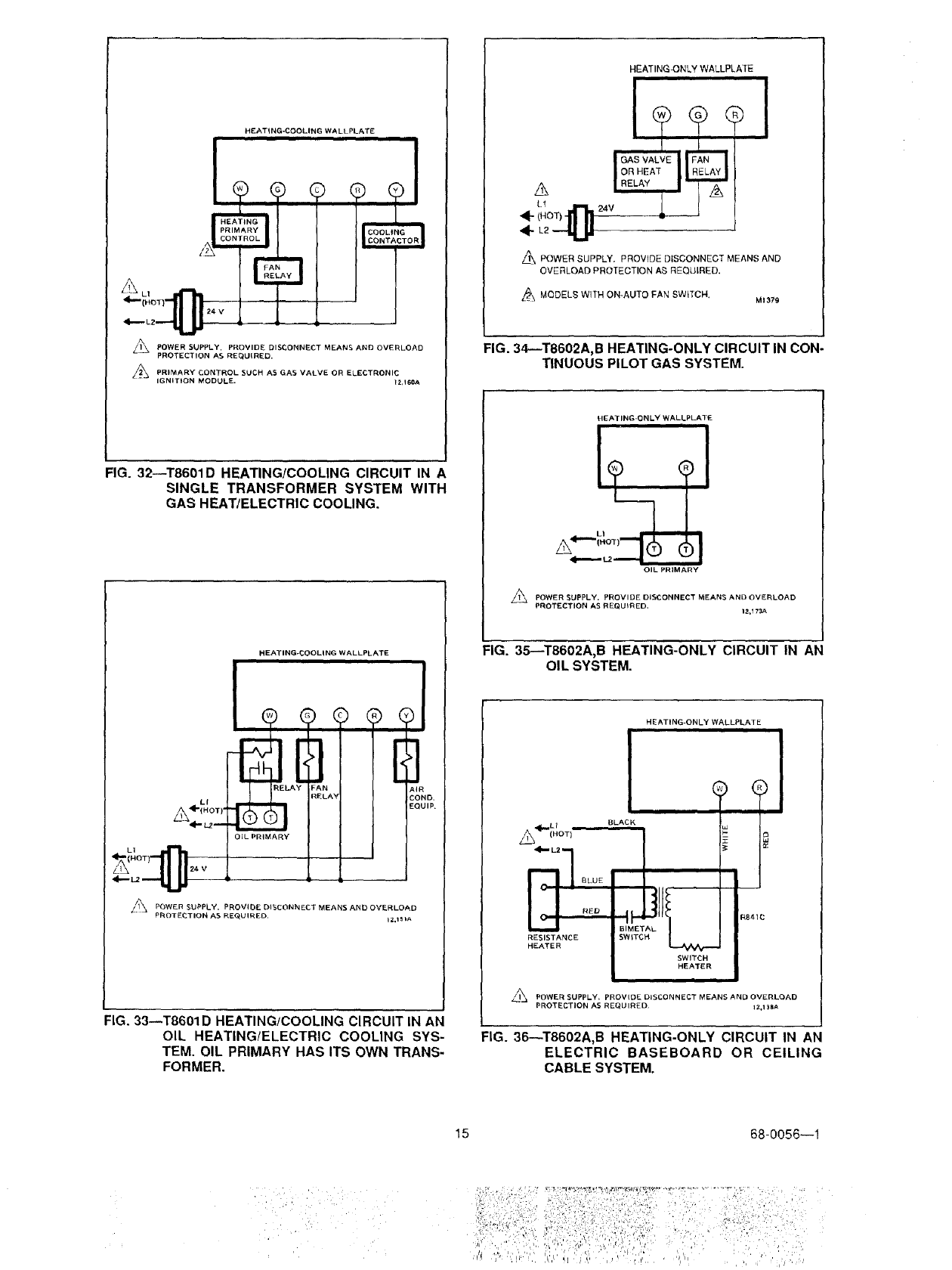
FIG. 32--T8601D HEATING/COOLING CIRCUIT IN A
SINGLE TRANSFORMER SYSTEM WITH
GAS HEAT/ELECTRIC COOLING.
HEATING-COOLING WALLPLATE
ELA _AN AIF
RELAY COl
LI
A÷,NOT,.@_L._3_-_-- EO,
OIL PRIMARY
//_ POWER SUPPLY. PROVIDE DISCONNECT MEANS AND OVERLOAD
PROTEDTION AS REQUIRED, iZ,151A
FIG. 33--T8601D HEATING/COOLING CIRCUIT IN AN
OIL HEATING/ELECTRIC COOLING SYS-
TEM. OIL PRIMARY HAS ITS OWN TRANS-
FORMER.
HEATINGJONLY WALLPLATE ii
A POWER SUPPLY. PROVIDE DISCONNECT MEANS AND
OVERLOAD PROTECTION AS REQUIRED.
A MODELS WITH ON-AUTO FAN SWITCH. M1379
FIG. 34--T8602A,B HEATING-ONLY CIRCUIT IN CON-
TINUOUS PILOT GAS SYSTEM.
HEATING-ONLY WALLPLATE
LI
A"
OIL PRIMARY
APOWER SUPPLY, PROVIDE DISCONNECT MEANS AND OVERLOAD
PROTECTION AS REQUIRED. 12,173A
FIG. 35--T8602A,B HEATING-ONLY CIRCUIT IN AN
OIL SYSTEM.
HEATING-ONLY WALLPLAT E
iiiiiii
ql{,_L 1 °
/L_ (HOT)
RED
RESISTANCE
HEATER
i i
BLACK
I
BIME'
SWtT(
SWITCH
HEATER
II IIIIIII
_j POWER SUPPLY= PROVIDE DISCONNECT MEANS AND OVERLOAD
PROTECTION AS REQUIRED¸ IZ.1 _A
FIG. 36_T8602A,B HEATING-ONLY CIRCUIT IN AN
ELECTRIC BASEBOARD OR CEILING
CABLE SYSTEM.
15 68-0056--1
.,III_L 1 =
(HOT)
ZONE1
HEATING ONLY WALLPLATE
®®
A
ZONEI I
MOTOR
_l_ POWER SUPPLY. PROVIDE DISCONNECT MEANS AND OVERLOAD
PROTECTION AS REQUIRED,
ZONE 2 ZONE 3 ZONE 4
HEATING ONLY WALLPLATE HEATING ONLY WALLPLATE HEATING ONLY WALLPLATE
I**1
'll
I
I,
I ,
I ZONE 4
DAMPER
MOTOR
USE ONE RBZ39 FOR EVERY FOUR ZONES. _USEFOR3-WIREZONEVALVEOROAMPERS.
12,150A
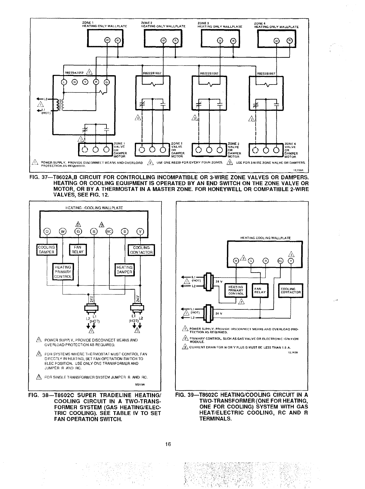
FIG. 37--T8602A,B CIRCUIT FOR CONTROLLING INCOMPATIBLE OR 3-WIRE ZONE VALVES OR DAMPERS.
HEATING OR COOLING EQUIPMENT IS OPERATED BY AN END SWITCH ON THE ZONE VALVE OR
MOTOR, OR BY A THERMOSTAT IN A MASTER ZONE. FOR HONEYWELL OR COMPATIBLE 2-WIRE
VALVES, SEE FIG. 12.
HEATING - COOLING WALLPLATE
HEATING
PRIMARY
CONTROL
L
L2 L! L1
(HOT) L2
POWER SUPPLY, PROVIDE DISCONNECT MEANS AND
OVERLOAD PROTECTION AS REQUIRED,
L_ FOR SYSTEMS WHERE THERMOS]AT MUST CONTROL FAN
DIRECTLY IN HEA'IING, SET FAN OPERATION SWITCH TO
ELEC POSITION. USE ONLY ONE TRANSFORMER AND
JUMPER R AND RC.
FOR SINGLE ]RANSFORMER SYSTEM JUMPER R AND RC,
M3_9A
HEATING COOLING WALLPLATE
A
_POWER SUPPLY. PROVIDE DISCONNECT MEANS AND OVERLOAD PRO-
TECTION AS REQUIRED.
_PRIMARY _ONTROL. SUCH AS GAS VALVE OR ELECTRONIC IGNITION
MODULE,
_ CURRENT DRAW FOR W OR Y PLUS G MUST BE LESS THAN ! ,6 A.
IZ,142B
FIG. 38--T8602C SUPER TRADELINE HEATING/
COOLING CIRCUIT IN A TWO-TRANS-
FORMER SYSTEM (GAS HEATING/ELEC-
TRIC COOLING). SEE TABLE IV TO SET
FAN OPERATION SWITCH.
FIG. 39--T8602C HEATING/COOLING CIRCUIT IN A
TWO-TRANSFORMER (ONE FOR HEATING,
ONE FOR COOLING) SYSTEM WITH GAS
HEAT/ELECTRIC COOLING, RC AND R
TERMINALS.
16
H EATING-COOLING WALLPLATE
24 V
Z_ PQWER SUPPLY, PROVIDE DISCONNECT MEANS AND OVERLOAD
PROTECTION AS REQUIRED,
PRIMARY CONTROL SUCH AS GAS VALVE, ELECTRONIC
IGNITION MODULE OR HF'ATING CONTAETOR. 12,169B
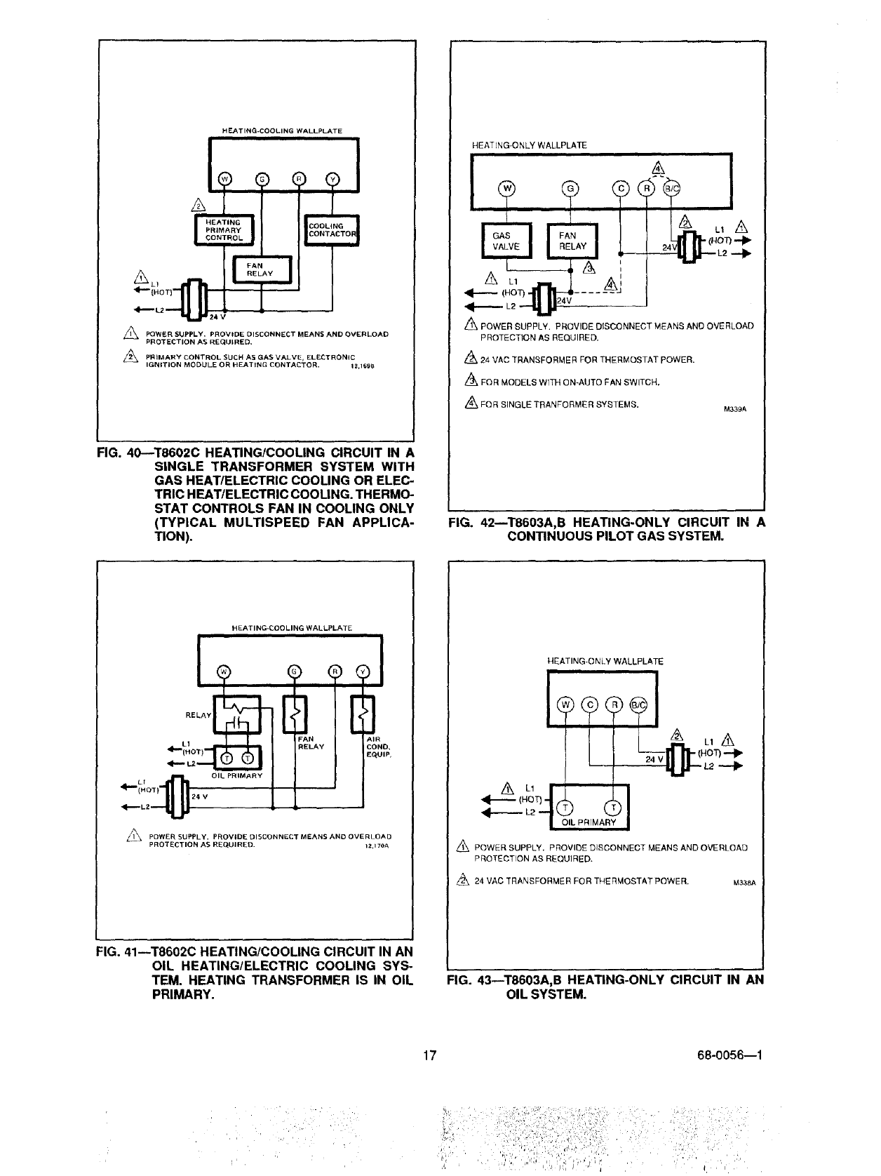
FIG. 40--T8602C HEATING/COOLING CIRCUIT IN A
SINGLE TRANSFORMER SYSTEM WITH
GAS HEAT/ELECTRIC COOLING OR ELEC-
TRIC HEAT/ELECTRIC COOLING. THERMG_
STAT CONTROLS FAN IN COOLING ONLY
(TYPICAL MULTISPEED FAN APPLICA-
TION).
HEATING-ONLY WALLPLATE
<i----- (HOT)-I1 _ .... -_-J
POWER SUPPLY. PROVIDE DISCONNECT MEANS AND OVERLOAD
PROTECTION AS REQUIRED.
_24 VAC TRANSFORMER FOR THERMOSTAT pOWER.
,_FOR MODELS WITH ON-AUTO FAN SWITCH,
_FQR SINGLE TRANFORMER SYSTEMS, M339A
FIG. 42--T8603A,B HEATING-ONLY CIRCUIT IN A
CONTINUOUS PILOT GAS SYSTEM.
HEATING-COOLING WALLPLATE
_i._Hf aT )lr_ 24 vOiL PRIMARY
<I_'LZ --'11 _
POWER SUPPLY• PROVIDE DISCONNECT MEANS AND OVERLOAD
PROTECTION AS REQUIRED. 12,170A
FIG. 41--T8602C HEATING/COOLING CIRCUIT IN AN
OIL HEATING/ELECTRIC COOLING SYS-
TEM. HEATING TRANSFORMER IS IN OIL
PRIMARY.
HEATING-ONLY WALLPLATE
Z_ POWER SUPPLY, PROVIDE DISCONNECT MEANS AND OVERLOAD
PROTECTION AS REQUIRED.
/_ 24 VAC TRANSFORMER FOR TNERMOSTATPOWER. MaaBA
FIG. 43--T8603A,B HEATING-ONLY CIRCUIT IN AN
OIL SYSTEM.
17 68-0056---1
ii,'_ ¸ _,,,, _ _, •,, " /, ,,

4--elioT1
L2L-_
A LI
ONNECTION SB6 VR_40
A,NVALVE Mv TH
oMMoN M,,,_vT.
'LOTVALV_PV THTR ! I
o!l
HEATING-ONLY WALLPLATE [
LIMIT I ]
_'AN CONTROLLER |I
$86 MODULE
i i
O
25 Mac q MV
25 Mac I MV/PV --
I PV
GND [-
O345, Q346.
z_ BURNER
IGNITER SENSOR
VR8440 VALVE
PILOT
BURNER
GROUND
POWER SUPPLY. PROVfDE DISCONNECT MEANS AND OVERLOAD
PROTECTION AS REQUIRED.
_ MAXIMUM PILOT BURNER IGNITER-SENSOR CABLE LENGTH:30 in. [0.8 m].
FACTORY-INSTALLED WIRES. DO NOT REMOVE.
l_\ CON1ROLS IN TRANSFORMER CIRCUIT MUST NOT BE IN GROUNDED LEG.
I
TO VR8440 PILOT OUTLET
L_ FOR MOQELS WITH ON-AUTO FAN SWITCH.
L!_ 2_ VAC TRANSFORMER FOR THERMOSTAT POWER.
Z_FOR SINGLE TRANSFORMER GYSTEMS.
_40A
FIG. 44--T8603A,B HEATING-ONLY CIRCUIT IN A HONEYWELL INTERMITTENT PILOT GAS BURNER IGNITION
SYSTEM.
ZONE 1 ZONE 2 ZONE 3
HEATING-ONLY WALLPLATE HEATING-ONLY WALLPLATE HEATING-ONLY WALLPLATE
/_,_ L1
(HOT)-
4--- L2
A
RB239A1052
i
ZONE 4
HEATING-ONLY WALLPLATE
iiiii
ZONE 1 VALVE OR
DAMPER MOTOR
RB222B1067
ZONE 2 VALVE OR
DAMPER MOTOR
_\ POWER SUPPLY. PROVIDE DISCONNECT MEANS AND OVERLOAD
PROTECTION AS REQUIRED.
/'_ USE ONE R82.39 FOR EVERY FOUR ZONES,
R8222B1067
iuu
ZONE 3 VALVE OR
DAMPER MOTOR
RB222B1067
ZONE4VALVEOR
DAMPER MOTOR
24 VAC TRANSFORMER FOR THERMOSTAT POWER.
FOR SINGLE TRANSFORMER SYSTEMS.
M333A
FIG. 45--T8603A,B CIRCUIT FOR CONTROLLING INCOMPATIBLE OR THREE-WIRE ZONE VALVES OR DAMPERS.
HEATING EQUIPMENT IS OPERATED BY AN END SWITCH ON THE ZONE VALVE OR MOTOR, OR BY A
THERMOSTAT IN A MASTER ZONE.
18
fiill¸ :d:ii i:;!i!i:f fiil!ii ,
: ,!i_,:dii_iL,,I,_:i,_
!ii_iiiii:_: i i ii_J:%&!::!_iil_
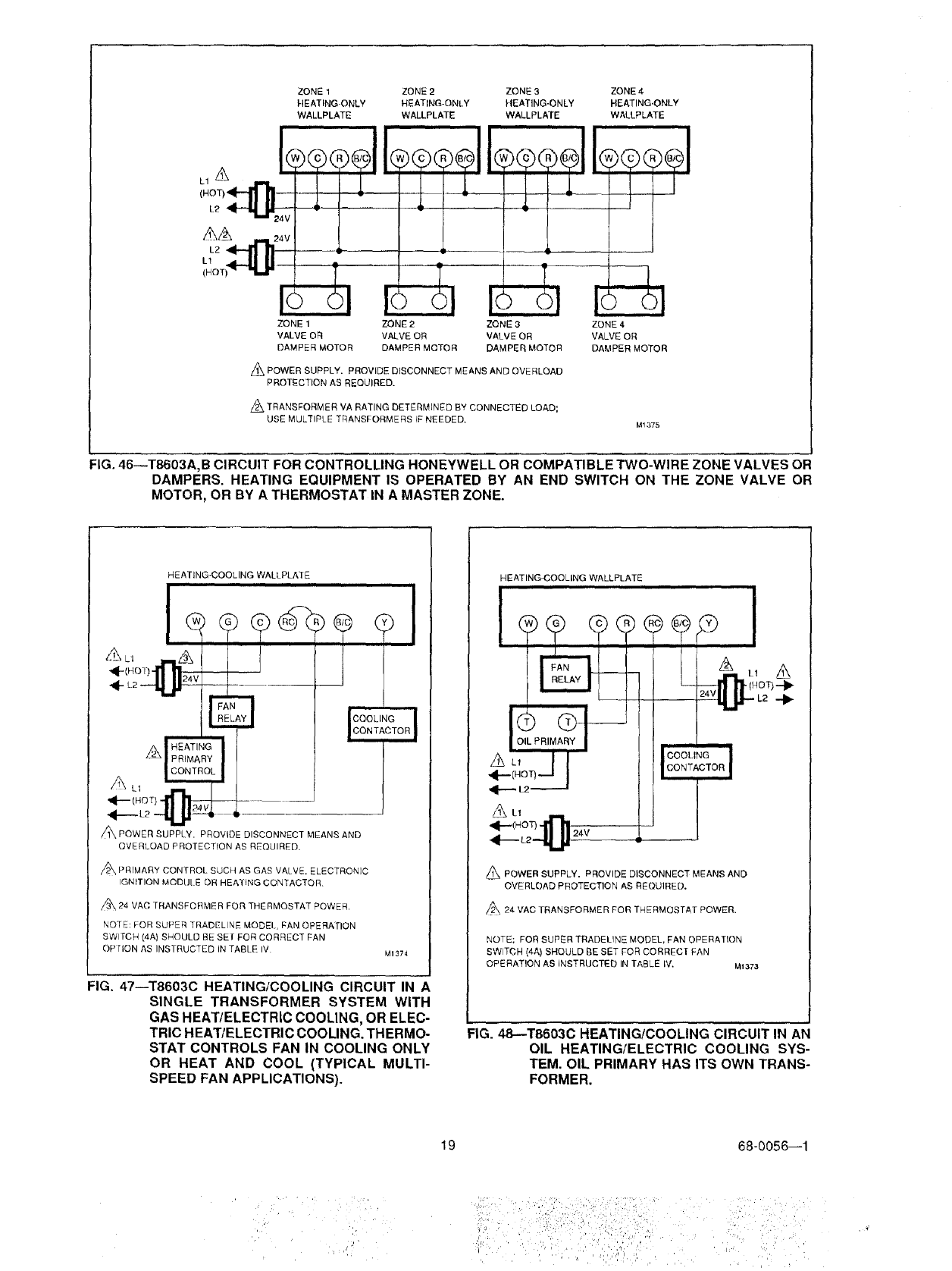
ZONE 1 ZONE 2 ZONE 3 ZONE 4
HEATING-ONLY HEATING-ONLY HEATING-ONLY HEATING-ONLY
WALLPLATE WALLPLATE WALLPLATE WALLPLATE
L1A
(NO]
L2
ZONE 1 ZONE 2 ZONE 3
VALVE OR VALVE OR VALVE OR
DAMPER MOTOR DAMPER MOTOR DAMPER MOTOR
Z_ POWER SUPPLY. PROVIDE DISCONNECT MEANS AND OVERLOAD
PROTECTION AS REQUIRED.
z_ TRANSFORMER VA RATING DETERMINED BY CONNECTED LOAD;
USE MULTIPLE TRANSFORMERS IF NEEDED,
ZONE 4
VALVE OR
DAMPER MOTOR
M1375
FIG• 46--T8603A,B CIRCUIT FOR CONTROLLING HONEYWELL OR COMPATIBLE TWO-WIRE ZONE VALVES OR
DAMPERS• HEATING EQUIPMENT IS OPERATED BY AN END SWITCH ON THE ZONE VALVE OR
MOTOR, OR BY A THERMOSTAT IN A MASTER ZONE.
HEATING*COOLING WALLPLATE
ii
AL_ --A
_c"ol_-II'll]_ V
AF
| PRIMA
A L,
L22_ _--v,
]
p-
(
COOLING
CONTACTOR
A
/1\ POWER SUPPLY. PROVIDE DISCONNECT MEANS AND
OVERLOAD PROTECTION AS REQUIRED,
A PRIMARY CONTROL SUCH AS GAS VAI VE. ELECTRONIC
IGNITION MODUI E OR HEALING CONTACTOR.
A 24 VAC TRANSFORMER FOR THERMOSTAT POWER.
NOTE: FOR SUPER TRADELINE MODEl, FAN OPERATION
SWITCH (4A) SHOULD BE SEI FOR CORRECT FAN
OP lION AS INSTRUCTED IN TABLE IV MI374
FIG. 47--T86030 HEATING/COOLING CIRCUIT IN A
SINGLE TRANSFORMER SYSTEM WITH
GAS HEAT/ELECTRIC COOLING, OR ELEC-
TRIC HEAT/ELECTRIC COOLING. THERMO-
STAT CONTROLS FAN IN COOLING ONLY
OR HEAT AND COOL (TYPICAL MULTI-
SPEED FAN APPLICATIONS).
HEATING4COOLING WALLPLATE
_ POWER SUPPLY. PROVIDE DISCONNECT MEANS AND
OVERLOAD PROTECTION AS REQUIRED.
/_24 VAC TRANSFORMER FOR THERMOSTAT POWER.
NOTE: FOR SUPER TRADELINE MODEL. FAN OPERATION
SWITCH (4A) SHOULD BE SET FOR CORRECT FAN
i
OF E RATION AS INSTRUCTED IN TABLE IV. Mi373
FIG. 48--T8603C HEATING!COOLING CIRCUIT IN AN
OIL HEATING/ELECTRIC COOLING SYS-
TEM. OIL PRIMARY HAS ITS OWN TRANS-
FORMER.
19 68-0056--1
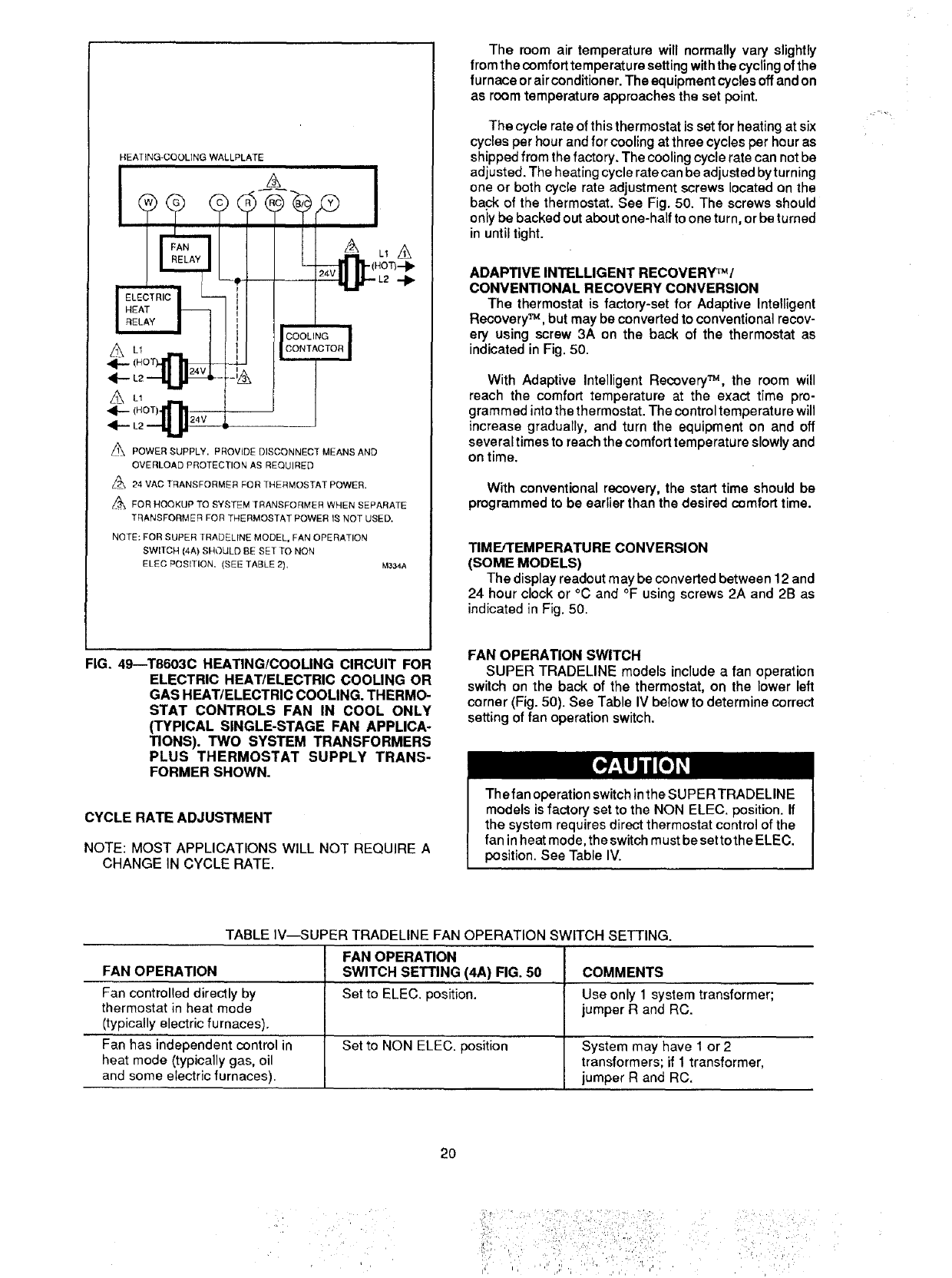
HEATING-COOLING WALLPLATE
L1
(HOT)
A
/1\ POWER SUPPLY. PROVIDE DISCONNECT MEANS AND
OVERLOAD PROTECTION AS REQUIRED
_ 24 VAC TRANSFORMER FOR THERMOSTAT POWER.
_FOR HOOKUP TO SYSTEM TRANSFORMER WHEN SEPARATE
TRANSFORMER FOR TRERMOSTAT POWER IS NOT USED.
NOTE: FOR SUPER TRADELINE MODEL, FAN OPERATION
SWITCH (4A) SHOULD BE SET TO NON
ELEC POSITION, (SEE TABLE 2}, M334A
The room air temperature will normally vary slightly
from the comfort temperature setting with the cycling of the
furnace orair conditioner.The equipment cycles offand on
as room temperature approaches the set point.
The cycle rate of this thermostat is set for heating at six
cycles per hour and for cooling at three cycles per hour as
shipped from the factory. The cooling cycle rate can not be
adjusted. The heating cycle rate can be adjusted byturning
one or both cycle rate adjustment screws located on the
back of the thermostat. See Fig. 50. The screws should
only be backed out about one-half to one turn, or be turned
in until tight.
ADAPTIVE INTELLIGENT RECOVERY_'_/
CONVENTIONAL RECOVERY CONVERSION
The thermostat is factory-set for Adaptive Intelligent
Recovery _, but may be converted to conventional recov-
ery using screw 3A on the back of the thermostat as
indicated in Fig. 50.
With Adaptive Intelligent Recovery _, the room will
reach the comfort temperature at the exact time pro-
gramm ed into the thermostat. The control temperature will
increase gradually, and turn the equipment on and off
several times to reach the comfort temperature slowly and
on time.
With conventional recovery, the start time should be
programmed to be earlier than the desired comfort time.
TIMFJTEMPERATURE CONVERSION
(SOME MODELS)
The display readout may be converted between 12 and
24 hour clock or °C and °F using screws 2A and 2B as
indicated in Fig. 50.
FIG. 49--T8603C HEATING/COOLING CIRCUIT FOR
ELECTRIC HEAT/ELECTRIC COOLING OR
GAS HEAT/ELECTRIC COOLING. THERMO-
STAT CONTROLS FAN IN COOL ONLY
(TYPICAL SINGLE-STAGE FAN APPLICA-
TIONS). TWO SYSTEM TRANSFORMERS
PLUS THERMOSTAT SUPPLY TRANS-
FORMER SHOWN.
CYCLE RATE ADJUSTMENT
NOTE: MOST APPLICATIONS WILL NOT REQUIRE A
CHANGE IN CYCLE RATE.
FAN OPERATION SWITCH
SUPER TRADELINE models include a fan operation
switch on the back of the thermostat, on the lower left
corner (Fig. 50). See Table IV below to determine correct
setting of fan operation switch.
The fan operation switch in the SUPER TRADELINE
models is factory set to the NON ELEC. position. If
the system requires direct thermostat control of the
fan in heat mode, the switch must be setto the ELEC.
position. See Table IV.
TABLE IV-SUPER TRADELINE FAN OPERATION SWITCH SETTING.
FAN OPERATION
FAN OPERATION SWITCH SETTING (4,6,) FIG. 50 COMMENTS
Fan controlled directly by Set to ELEC. position. Use only 1 system transformer;
thermostat in heat mode jumper R and RC.
(typically electric furnaces).
Fan has independent control in Set to NON ELEC. position System may have 1 or 2
heat mode (typically gas, oil transformers; if 1 transformer,
and some electric furnaces), jumper R and RC.
2O
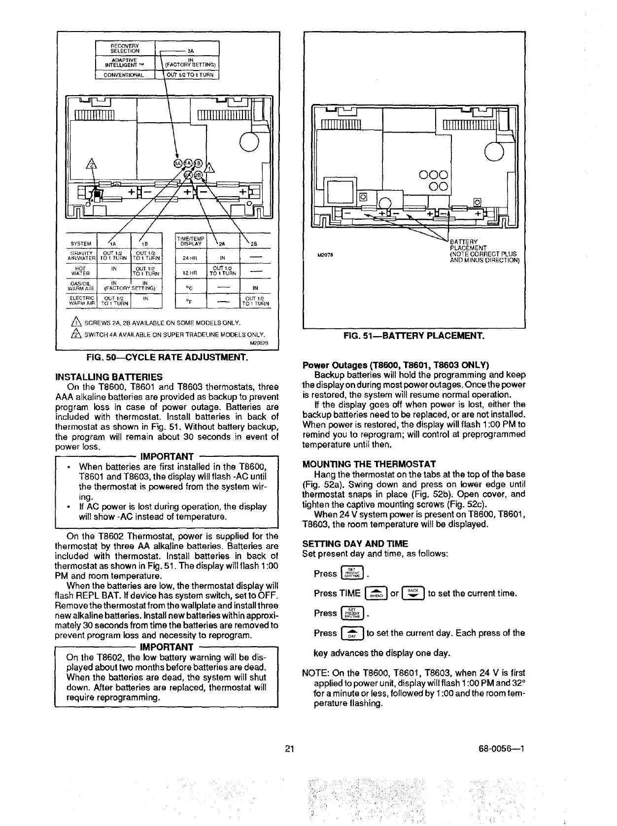
RECOVERY
SELECTION _3A
ADAPTIVE ' IN
INTELLIGENT _ , Y SETTING)
_CONVENTIONAL __ _OUT I_ "fO 1 TURN
,X
S,STEMd"
OUT It2 OUT 1f2
TO 1 TURN TO 1 TURN
IN OUT lz2
TO 1 TURN
-- (FACTORY SETTING)
OUT 1/Z IN
/
TEME/rEMP
DISPLAY
24 HR
12HR
o¢
o F
G_'!AVITY
At_AT EIq
HOT
WATER
GAS/OIL
WARM AIR
ELEOTRhC
WARM AIR
A SCREWS 2A, 2B AVAILABLE ON SOME MODELS ONLY.
Z_ SWITCH 4A AVAILABLE ON SUPER TRADELINE MODELS ONLY.
M2082B
FIG. 5D--CYCLE RATE ADJUSTMENT.
INSTALLING BATTERIES
On the T8600, T8601 and T8603 thermostats, three
AAA alkaline batteries are provided as backup to prevent
program loss in case of power outage. Batteries are
included with thermostat. Install batteries in back of
thermostat as shown in Fig. 51. Without battery backup,
the program will remain about 30 seconds in event of
3ower loss. IMPORTANT
•When batteries are first installed in the T8600,
T8601 and T8603, the display will flash -AC until
the thermostat is powered from the system wir-
ing.
If AC power is lost during operation, the display
will show -AC instead of temperature.
On the T8602 Thermostat, power is supplied for the
thermostat by three AA alkaline batteries. Batteries are
included with thermostat. Install batteries in back ol
thermostat as shown in Fig. 51. The display will flash 1:00
PM and room temperature.
When the batteries are low, the thermostat display will
flash REPL BAT. If device has system switch, set to OFF.
Re move the thermostat from the wallplate and install three
new alkaline batteries. Install new batteries within approxi-
mately 30 seconds from time the batteries are removed to
prevent program loss and necessity to reprogram.
IMPORTANT
On the T8602, the low battery warning will be dis-
played about two months before batteries are dead.
When the batteries are dead, the system will shut
down. After batteries are replaced, thermostat will
require reprogramming.
OOC
_ O0
_'_J BATIE RY
PLACEMENT
M2OTS (NOTE CORRECT PLUS
AND MINUS DIRECTION)
FIG. 51--BATTERY PLACEMENT.
Power Outages (T8600, T8601, T8603 ONLY)
Backup batteries will hold the programming and keep
the display on during most power outages. Once the power
is restored, the system will resume normal operation.
If the display goes off when power is lost, either the
backup batteries need to be replaced, or are not installed.
When power is restored, the display will flash 1:00 PM to
remind you to reprogram; will control at preprogrammed
temperature until then.
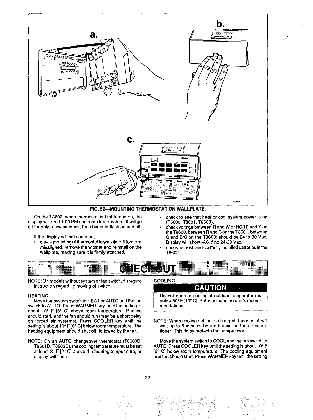
MOUNTING THE THERMOSTAT
Hang the thermostat on the tabs at the top of the base
(Fig. 52a). Swing down and press on lower edge until
thermostat snaps in place (Fig. 52b). Open cover, and
tighten the captive mounting screws (Fig. 52c).
When 24 V system power is present on T8600, T8601,
T8603, the room temperature will be displayed.
SETTING DAY AND TIME
Set present day and time, as follows:
Press _.
Press TIME _or |to set the current time.
Press _.
Press C_ to set the current day. Each press of the
key advances the display one day.
NOTE: On the T8600, T8601, T8603, when 24 V is first
applied to power unit, display will flash 1:00 PM and 32°
for a minute or less, followed by 1:00 and the room tem-
perature tlashing.
21 68-0056--1
iil i• ¸ ,!!!i! •¸¸¸
;I 'ii', :i/; ,: !{i _''. .... '
ai
bll
ci
rY
!2,18OB
FIG. 52--MOUNTING THERMOSTAT ON WALLPLATE.
On the T8602, when thermostat is first turned on, the
display will read 1:00 PM and room temperature. It will go
off for only a few seconds, then begin to flash on and off.
•check to see that heat or cool system power is on
(T8600, T8601, T8603).
•check voltage between R and W or RC(R) and Y on
the T8600, between R and C on the T8601, between
C and B/C on the T8603; should be 24 to 30 Vac.
Display will show -AC if no 24-30 Vac.
•check for fresh and correctly installed batteries in the
T8602.
If the display will not come on,
•check mounting of thermostat to wallplate. If loose or
misaligned, remove thermostat and reinstall on the
wallplate, making sure it is firmly attached.
iiiiiiiii'il:iii iii iiiiiiiiii iiii i!!iiiii!iiiiiiiili!!i!!ii iiiiiii !! iiii! ! !U ii ii!i ii!!iii i!! iii!i!i iii iii!! ii iii!iiiiiiii 1ii ii iiii iiii ! iiiiiiiiii i i i
NOTE: On models without system or fan switch, disregard
instruction regarding moving of switch.
HEATING
Move the system switch to HEAT or AUTO and the fan
switch to AUTO. Press WARMER key until the setting is
about 10°F [6 °C] above room temperature. Heating
should start, and the fan should run (may be a short delay
on forced air systems). Press COOLER key until the
setting is about 10° F [6 ° C] below room temperature. The
heating equipment should shut off, followed by the fan.
NOTE: On an AUTO changeover thermostat (T8600D,
T8601 D, T8602D), the cooling temperature must be set
at least 3 °F [2 ° C] above the heating temperature, or
display will flash.
COOLING
Do not operate cooling if outdoor temperature is
below 50°F [10°C]. Refer to manufacturer's recom-
mendations.
NOTE: When cooling setting is changed, thermostat will
wait up to 5 minutes before turning on the air condi-
tioner. This delay protects the compressor.
Move the system switch to COOL and the fan switch to
AUTO. Press COOLER key until the setting is about 10°F
[6 ° C] below room temperature. The cooling equipment
and fan should start. Press WARMER key until the setting
22
ili!ili!: ii !ii!i!i i:: i ili!ii illil
:i: _ ill:! ,_,i_: : i_!::
• _ _ !!_!iii!_!!i!_!I:I!_ iiii _i i,_
is about 10 °F [6 °C] above room temperature. The cooling
equipment and fan should stop.
NOTE: On an AUTO changeover thermostat (T8600D,
T8601 D, T8602D), the heating temperature must be set
at least 3° F [2° C] below the cooling temperature, or
display will flash.
FAN
Move the system switch to OFF, and the fan switch to
ON. The fan should run continuously. When the fan switch
is in the AUTO position, fan cycles with the heating or
cooling system.
INSTALLER SELF-TEST (optional)
IMPORTANT
Five minute time delay on cooling does not function
during self-test.
Perform the following test as a check of all thermostat
functions, ff thermostat does not respond as indicated,
thermostat must be replaced.
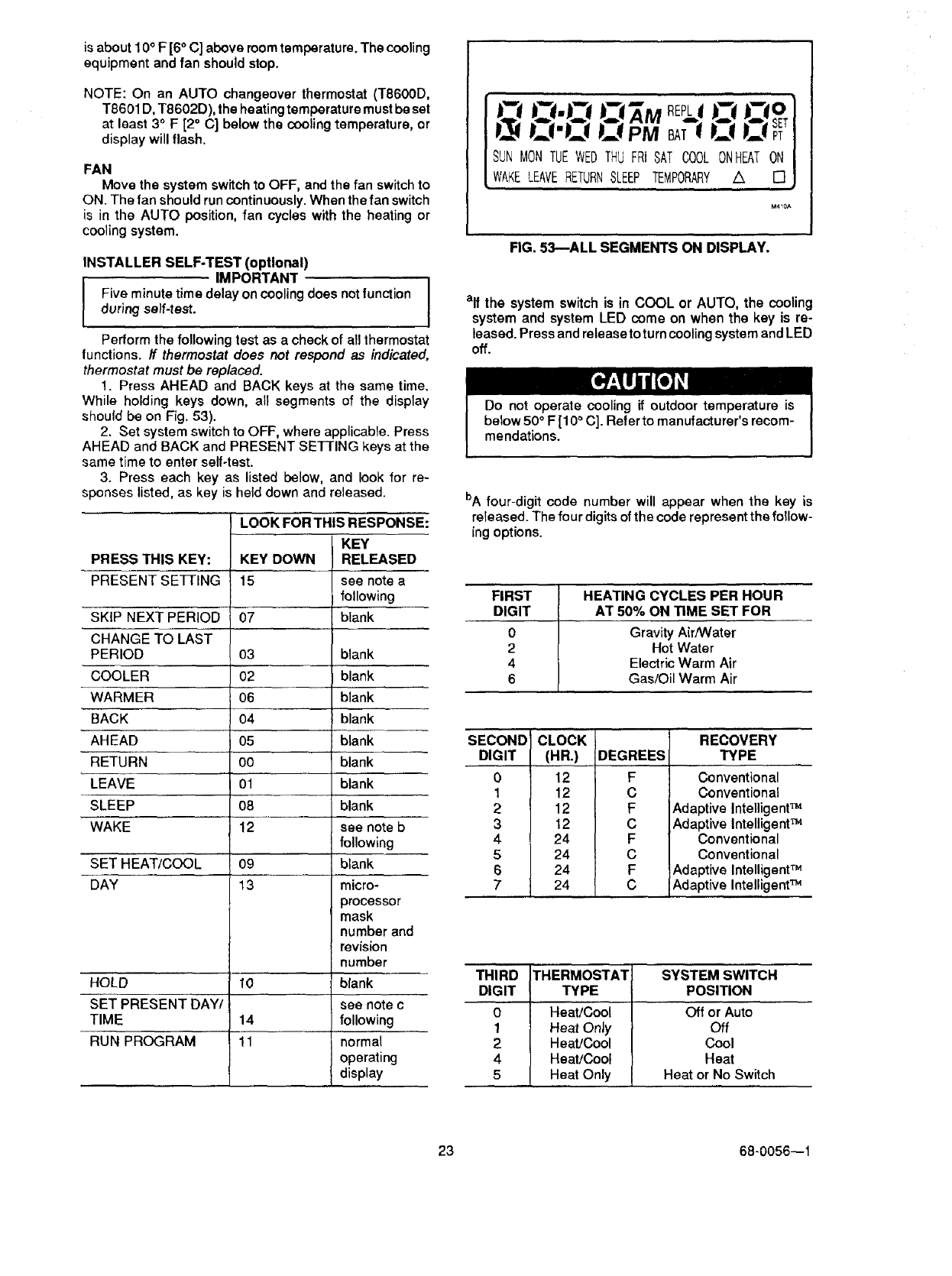
1. Press AHEAD and BACK keys at the same time.
While holding keys down, all segments of the display
should be on Fig. 53).
2. Set system switch to OFF, where applicable. Press
AHEAD and BACK and PRESENT SETTING keys at the
same time to enter self-test.
3. Press each key as listed below, and look for re-
sponses listed, as key is held down and released.
PRESS THIS KEY: KEY DOWN
PRESENT SEFrlNG 15
SKIP NEXT PERIOD
CHANGE TO LAST
PERIOD 03 blank
COOLER 02 blank
WARMER 06 blank
BACK 04 blank
AHEAD 05 blank
RETURN 00 blank
LEAVE 01 blank
SLEEP 08 blank
WAKE 12 see note b
following
SET HEAT/COOL 09 blank
DAY 13 micro-
processor
mask
number and
revision
number
HOLD 10 blank
SET PRESENT DAY/ see note c
TIME 14 following
RUN PROGRAM 11 normal
operating
display
LOOK FOR THIS RESPONSE:
KEY
RELEASED
see note a
following
07 blank
SUN MON TUEWEDTHU FRI SAT COOL ONHEATON
WAKELEAVERETURNSLEEP TEMPORARY A []
M40A
FIG. 53--ALL SEGMENTS ON DISPLAY.
elf the system switch is in COOL or AUTO, the cooling
system and system LED come on when the key is re-
leased. Press and release to turn cooling system and LED
off.
Do not operate cooling if outdoor temperature is
below 50°F [10 ° C]. Refer to manufacturer's recom-
mendations.
bA four-digit code number will appear when the key is
released. The four digits of the code represent the follow-
ing options.
FIRST HEATING CYCLES PER HOUR
DIGIT AT 50% ON TIME SET FOR
0Gravity Air/Water
2 Hot Water
4 Electric Warm Air
6 Gas/Oil Warm Air
SECOND
DIGIT
0
1
2
3
4
5
6
7
CLOCK
(HR.)
12
12
12
12
24
24
24
24
DEGREES
F
C
F
C
F
C
F
C
RECOVERY
TYPE
Conventional
Conventional
Adaptive IntelligentTM
Adaptive Intelligent TM
Conventional
Conventional
Adaptive IntelligentTM
Adaptive IntelligentTM
THIRD THERMOSTAT SYSTEM SWITCH
DIGIT TYPE POSITION
0 Heat/Cool Off or Auto
1 Heat Only Off
2 Heat/Cool Cool
4 Heat/Cool Heat
5 Heat Only Heat or No Switch
23 68-0056--1
FOURTH
0
1
3
4
5
7
DIGIT THERMOSTAT
T8602
T8602
T8602
T8600, T8601, T8603
T8600, T8601, T8603
T8600, T8601, T8603
AUTO OR
MANUALCHANGEOVER
Manual or Heat Only
Auto
Auto
Manual or Heat Only
Auto
Auto
SYSTEM SWITCH
All Positions
Heat, Off, Cool
Auto
All Positions
Heat, Off, Cool
Auto
elf the system switch is in HEAT or AUTO, the heating system and system LED come on when the key is released. Press
and release again to turn heating system and LED off.
•Peopleperceivetemperaturefromavarietyofsources,
not only from the air in the room, but also from their
surroundings--walls, windows and furnishings.
•Humanbeingsfeeldifferencesintemperatureasslight
as two degrees Fahrenheit.
• Common household thermometers and standard
thermostats sense only air temperature, which may or may
not reflect how hot or cold the room actually feels to a
human being.
• This thermostat reads the temperature of the wall as
well as the air--and responds to temperature changes as
little as one degree Fahrenheit--so room temperature is
more likely to "feel right".
THE OPTIMUM COMFORT AND ENERGY SAVINGS SOLUTION
•This thermostat is actually a small but powerful com-
puter. When calculating the exact time to turn on your
furnace or air conditioner, it considers (1) air temperature,
(2) the temperature of the wall and (3) when you want the
comfort temperature established.
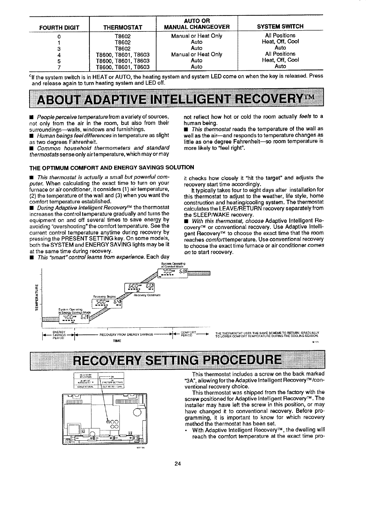
• DuringAdaptive IntelligentRecovery TM thethermostat
increases the control temperature gradually and turns the
equipment on and off several times to save energy by
avoiding "overshooting" the comfort temperature. See the
current control temperature anytime during recovery by
pressing the PRESENT SETTING key. On some models,
beth the SYSTEM and ENERGY SAVING lights may be lit
at the same time during recovery.
• This "smart" control learns from experience. Each day
Sy_lem Opera,rig ,;:-:1-"
InEnergy 8avirq_ Mode .::,""
• J
V I I I
-if---- SAVINGS ,_ _ RECOVERY FROM ENERGY _AVING$
PERIOD TIME
it checks how closely it "hit the target" and adjusts the
recovery start time accordingly.
It typically takes four to eight days after installation for
this thermostat to adjust to the weather, life style, home
construction and heating/cooling system. The thermostat
calculates the LEAVE/RETURN recovery separately from
the SLEEP/WAKE recovery.
• With this thermostat, choose Adaptive Intelligent Re-
covery TM or conventional recovery. Use Adaptive Intelli-
gent Recovery TM to choose the exact time that the room
reaches comforttemperature. Use conventional recovery
to choose the exact time furnace or air conditioner comes
on to start recovery.
TNE THERMOSTAT USES THE SAM ESCHEME TO RETURN GRADUALLY
TO LOWER COMFOF_T TEMPERATURE DU_NG TF_E COOLING SFJ_ON.
This thermostat includes a screw on the back marked
"3A", allowing for the Adaptive Intelligent Recovery_/con -
ventional recovery choice.
This thermostat was shipped from the factory with the
screw positioned for Adaptive Intelligent Recovery TM .The
installer may have left the screw in this position, or may
have changed it to conventional recovery. Before pro-
gramming, it is important to know for which recovery
method the thermostat has been set.
• With Adaptive Intelligent Recovery TM, the dwelling will
reach the comfort temperature at the exact time pro-
24
grammedinto the thermostat. See page 24 for detailed
explanation of Adaptive Intelligent Recovery TM .
•With conventional recovery, the programmed time will
mark the start of recovery; therefore, program the start
time to be earlier than the desired comfort time. It may
require some trial and error to arrive at the best starting
time, and the best starting time will vary as the seasons •
change.
To determine which type of recovery is set into the
thermostat, make sure thermostat is powered with fresh
batteries, or is mounted and powered on the wall (see page
22).
Press LRRq_U_AU_key. •
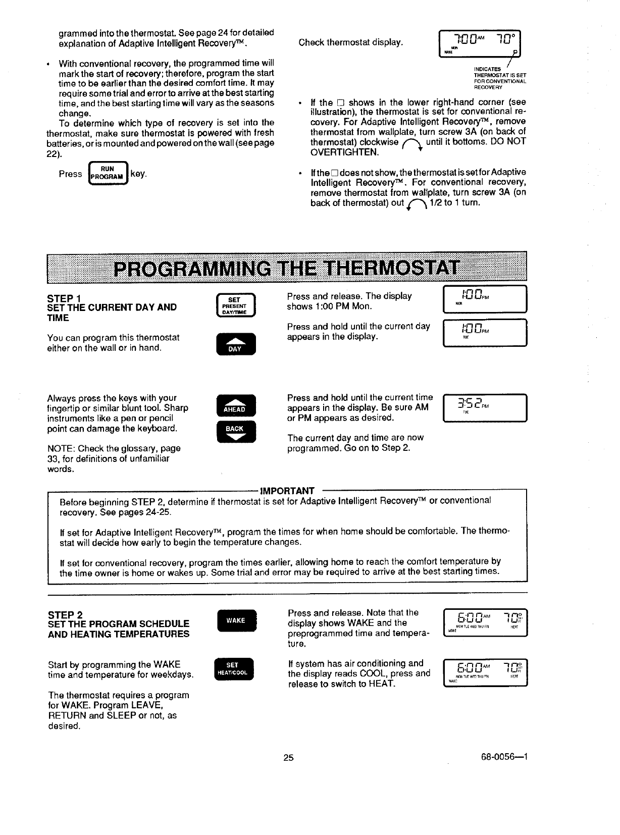
Check thermostat display. I 70° I
I.LI U
/
INDICATES
THERMOSTAT IS SET
FOR CONVENTIONAL
REGOVEF_Y
ff the E3 shows in the lower right-hand corner (see
illustration), the thermostat is set for conventional re-
covery. For Adaptive Intelligent Recovery TM, remove
thermostat from wallplate, turn screw 3A (on back of
thermostat) clockwise ('_ until it bottoms. DO NOT
OVERTIGHTEN.
Ifthe [] does not show, the thermostat is set for Adaptive
Intelligent Recovery TM. For conventional recovery,
remove thermostat from wallplate, turn screw 3A (on
back of thermostat) out _ 1/2 to 1 turn.
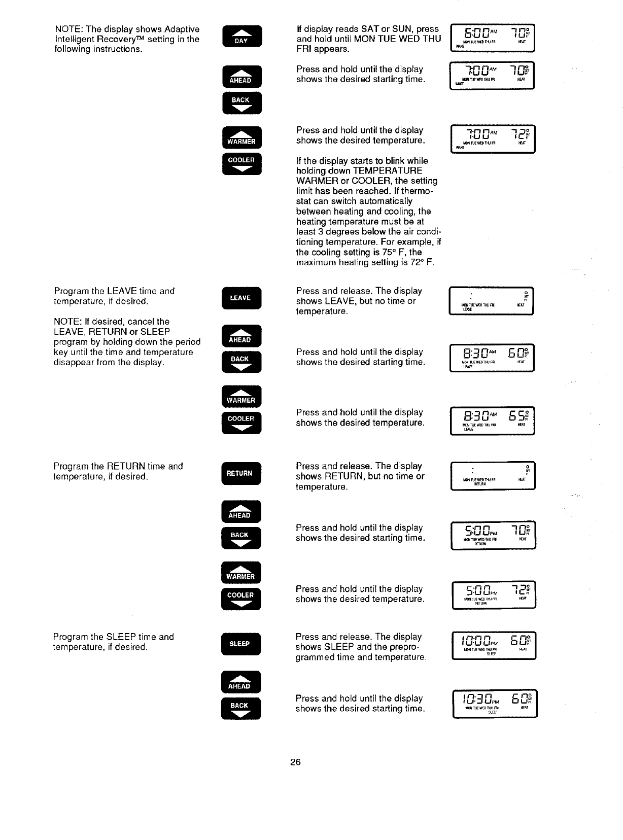
STEP1
SETTHE CURRENT DAY AND
TIME
You can program this thermostat
either on the wall or in hand.
I '°° I
Press and release. The display f.u uP_
shows 1:00 PM Mon. ,0,
Press and hold until the current day H__j'r7upMr7 J
appears in the display ....
Always press the keys with your
fingertip or similar blunt tool Sharp
instruments like a pen or pencil
point can damage the keyboard.
NOTE: Check the glossary, page
33, for definitions of unfamiliar
words.
Press and hold until the current time
appears in the display. Be sure AM
or PM appears as desired.
The current day and time are now
programmed. Go on to Step 2.
I -f- "7 J
_._7CPM
TUE
IMPORTANT
Before beginning STEP 2, determine if thermostat is set for Adaptive Intelligent Recovery TM or conventional
recovery. See pages 24-25.
If set for Adaptive Intelligent Recovery TM, program the times for when home should be comfortable. The thermo-
stat will decide how early to begin the temperature changes.
If set for conventional recovery, program the times earlier, allowing home to reach the comfort temperature by
the time owner is home or wakes up. Some trial and error may be required to arrive at the best starting times.
STEP2
SETTHE PROGRAM SCHEDULE
AND HEA_NG TEMPERATURES
Start by programming the WAKE
time and temperature for weekdays.
The thermostat requires a program
for WAKE. Program LEAVE,
RETURN and SLEEP or not, as
desired.
Press and release. Note that the
display shows WAKE and the
preprogrammed time and tempera-
ture.
If system has air conditioning and
the display reads COOL, press and
release to switch to HEAT.
I5.,30,,M
°,............l °J
• J
I60
K V,AK£,_3_TUF _#p_THU Fnl 14_T
25 68-0056--1
NOTE:ThedisplayshowsAdaptive
IntelligentRecovery_ settinginthe
followinginstructions•
ProgramtheLEAVEtimeand
temperature,ifdesired.
NOTE:Ifdesired,cancelthe
LEAVE,RETURNorSLEEP
programbyholdingdowntheperiod
keyuntilthetimeandtemperature
disappearfromthedisplay.
ProgramtheRETURNtimeand
temperature,ifdesired•
ProgramtheSLEEPtimeand
temperature,ifdesired.
IfdisplayreadsSATorSUN,press
andholduntilMONTUEWEDTHU
FRIappears.
Pressandholduntilthedisplay
showsthedesiredstartingtime.
Pressandholduntilthedisplay
showsthedesiredtemperature.
Ifthedisplaystartstoblinkwhile
holdingdownTEMPERATURE
WARMERorCOOLER,thesetting
limithasbeenreached.Ifthermo-
statcanswitchautomatically
betweenheatingandcooling,the
heatingtemperaturemustbeat
least3degreesbelowtheaircondi-
tioningtemperature.Forexample,if
thecoolingsettingis75"F,the
maximumheatingsettingis72°F.
Pressandrelease•Thedisplay
showsLEAVE,butnotimeor
temperature.
Press and hold until the display
shows the desired starting time.
Press and hold until the display
shows the desired temperature.
Press and release• The display
shows RETURN, but no time or
temperature•
Press and hold until the display
shows the desired starting time.
Press and hold until the display
shows the desired temperature.
Press and release. The display
shows SLEEP and the prepro-
grammed time and temperature.
Press and hold until the display
shows the desired starting time•
26
• -_mo
I A° ,-,I
I"°°°'g°l
/,u t.,J
v#a_E
,_,,_A. 72_I
_.u LJ
_ IuE w_T_J R_I
LE_E
8:30 _" 60_]
M_ fUE'_[_TNU Fr_ I_AT
[E,_E
J ::]D" ,SS_'[
_e_rue _D _J FRI _r_tr
_tuR_
I'°°° 1
,_-u_oM 80_
S_F_
[ "-"_ 80_J
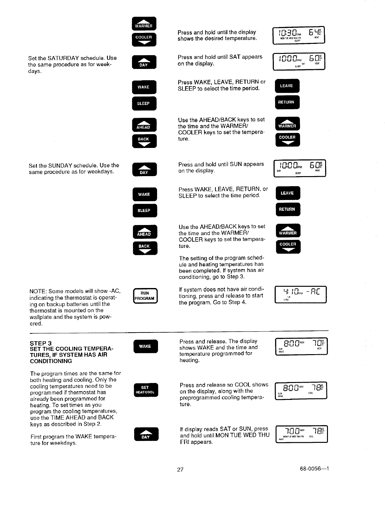
Set the SATURDAY schedule. Use
the same procedure as for week-
days.
Pressandholduntilthedisplay i _n'_n_u._uPM6_° Ishows the desired temperature. ,_,_w_,,u_
S_EP
on the display, tu.u upM
Press WAKE, LEAVE, RETURN or
SLEEP to select the time period.
Use the AHEAD/BACK keys to set
the time and the WARMER/
COOLER keys to set the tempera-
ture.
Sel the SUNDAY schedule. Use the
same procedure as lor weekdays. onPreSStheanddisplay.hOlduntil SUN appears J ,_,f_r'_.mu.uu_Mn_,,,6 ,_ J
Press WAKE, LEAVE, RETURN, or
SLEEP to select the time period.
NOTE: Some models will show -AC,
indicating the thermostat is operat-
ing on backup batteries until the
thermostat is mounted on the
wallplate and the system is pow-
ered.
Use the AHEAD/BACK keys to set
the time and the WARMER/
COOLER keys to set the tempera-
ture.
The setting ot the program sched-
ule and heating temperatures has
been completed. If system has air
conditioning, go to Step 3.
If system d°es n°t have air c°ndi" I JJ'an ]
tioning, press and release to start 7_, tu,_ - _
the program. Go to Step 4. _'
STEP 3
SET THE COOLING TEMPERA-
TURES, IF SYSTEM HAS AIR
CONDITIONING
The program times are the same for
both heating and cooling. Only the
cooling temperatures need to be
programmed if thermostat has
already been programmed for
heating. To set times as you
program the cooling temperatures,
use the TIME AHEAD and BACK
keys as described in Step 2.
First program the WAKE tempera-
ture for weekdays.
Press and release. The display
shows WAKE and the time and
temperature programmed for
heating.
i8:00 f LI_
Press and release so COOL shows I-f._7r3AM ]_,J
on the display, along with the _-u u
SUN cr_
preprogrammed cooling tempera ....
ture.
-I.n I--IAM
If display reads SAT °r SUN' press I ,-uu 78_J
and hold until MON TUE WED THU L,_,_ .............. j
FRI appears.
27 68-0056--1
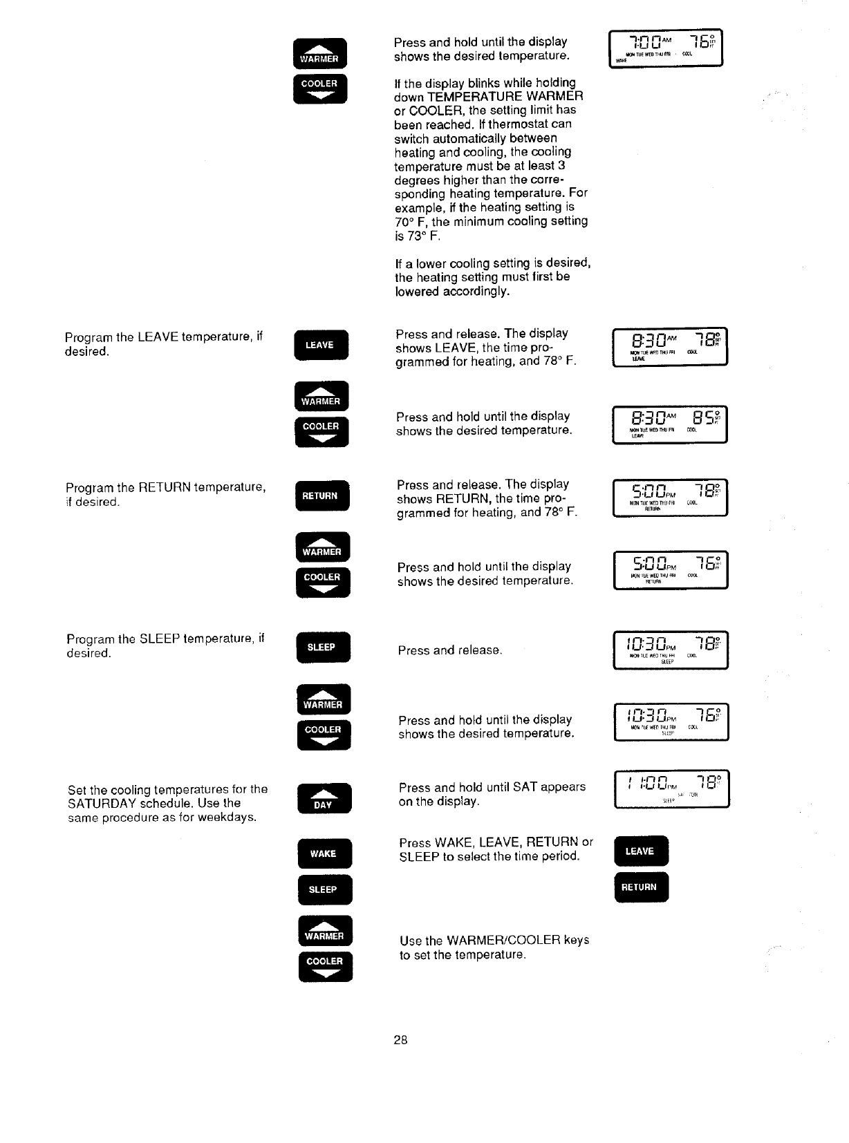
Pressandholduntilthedisplay
showsthedesiredtemperature.
Ifthedisplayblinkswhileholding
downTEMPERATUREWARMER
orCOOLER,thesettinglimithas
beenreached.Ifthermostatcan
switchautomaticallybetween
heatingandcooling,thecooling
temperaturemustbeatleast3
degreeshigherthanthecorre-
spondingheatingtemperature.For
example,iftheheatingsettingis
70°F, the minimum cooling setting
is 73° F.
If a lower cooling setting is desired,
the heating setting must lirst be
lowered accordingly.
I
I.LI U
Program the LEAVE temperature, if
desired.
Press and release. The display
shows LEAVE, the time pro-
grammed for heating, and 78°F.
_TL_ _*B3 TN/E_ql
Press and hold until the display
shows the desired temperature. va_l[_u_wee mu F_
Program the RETURN temperature,
if desired.
Press and release. The display
shews RETURN, the time pro-
grammed for heating, and 78° F. _BU_
[o.ooo]
_.,I•I,_1 I,_t pM #'
I_N IUL _ IHU P_I
IU'_ UPM
I U'J UPM
SLiP
I'1__1 I__IpM
_L_Ie A
Press and hold until the display
shows the desired temperature.
Program the SLEEP temperature, if
desired. Press and release.
Set the cooling temperatures for the
SATURDAY schedule. Use the
same procedure as for weekdays.
Press and hold until the display
shows the desired temperature.
Press and hold until SAT appears
on the display.
Press WAKE, LEAVE, RETURN or
SLEEP to select the time period.
Use the WARMER/COOLER keys
to set the temperature.
28
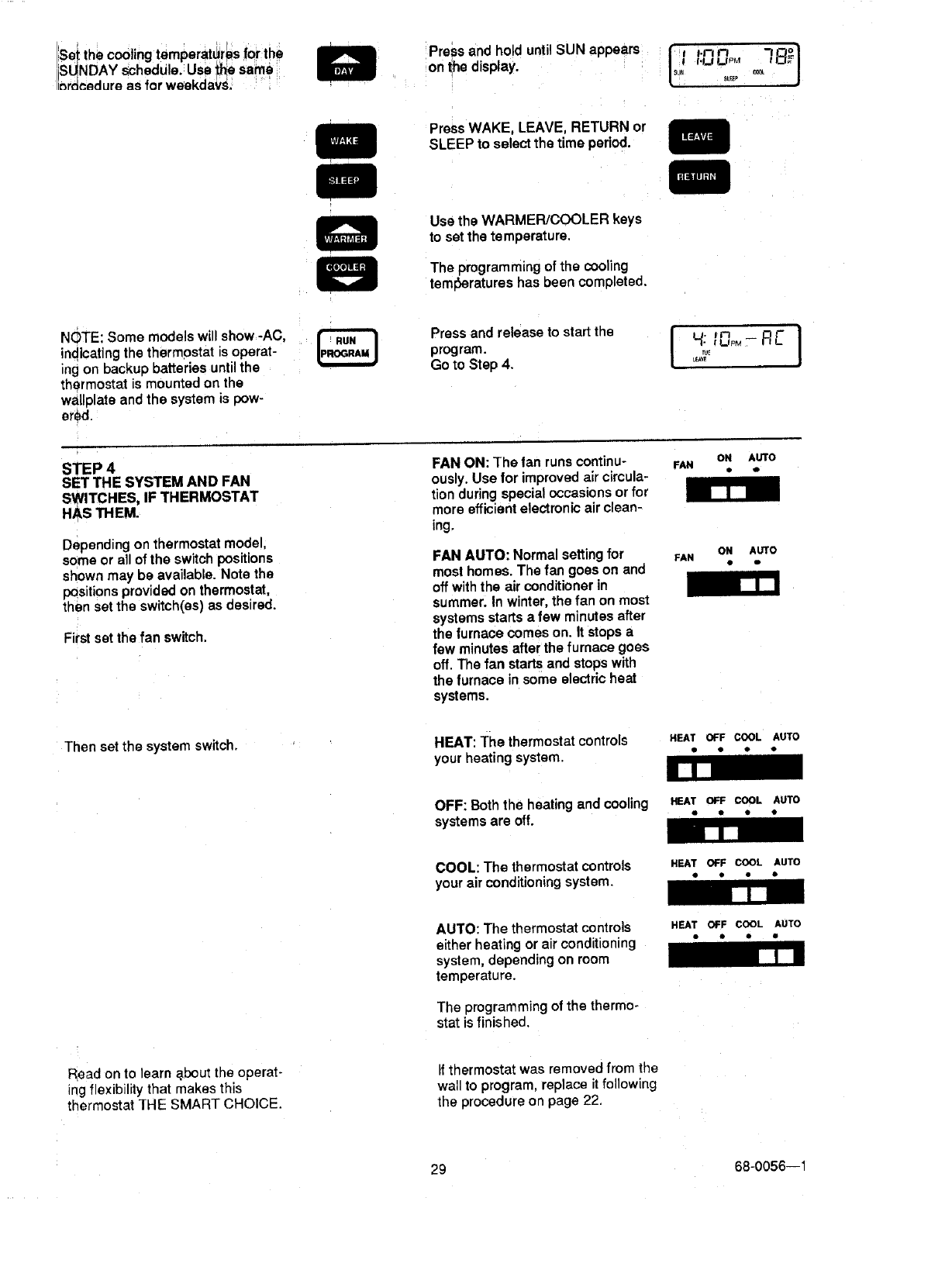
Set the cooling temperatures for the
ISUNDAY schedu e. Use _he same
inr_€_dure as for weekdaYs. Press and hold until SUN appears tlsu" _ +]/
on the display. _ i.ul'nupon 7 _°o
St_E_ _
Press WAKE, LEAVE, RETURN or
SLEEP to select the time period.
Use the WARMER/COOLER keys
to set the temperature.
The programming of the cooling
tem_eratures has been completed.
NOTE: Some models will show -AC,
indicating the thermostat is operat-
ing on backup batteries until the
thermostat is mounted on the
waltplate and the system is pow-
ered
Press and release to start the
program.
Go to Step 4. I_VE
STEP 4
SET THE SYSTEM AND FAN
SWITCHES, IF THERMOSTAT
HAS THEM. [lJ
Depending on thermostat model,
some or all of the switch positions
shown may be available. Note the
positions provided on thermostat,
then set the switch(es) as desired.
First set the fan switch.
FAN ON: The tan runs continu-
ously. Use for improved air circula-
tion during special occasions or for
more efficient electronic air clean-
ing.
FAN AUTO: Normal setting for
most homes. The fan goes on and
off with the air conditioner in
summer. In winter, the fan on most
systems starts a few minutes after
the furnace comes on. Itstops a
few minutes after the furnace goes
off. The fan starts and stops with
the furnace in some electric heat
systems.
ON AUTO
• o
ON AUTO
FAN D Q
Then set the system switch. HEAT: The thermostatcontrols HEATOFFCOOLAUTO
your heating system. " " " "
OFF: Both the heating and cooling HEATOFF COOL AUTO
systems are off. " * *•
U[_J
COOL: The thermostat controls HEATOFF COOL AUTO
your air conditioning system. • " • •
R_ad on to learn _bout the operat-
ing flexibility that makes this
thermostat THE SMART CHOICE.
AUTO: The thermostat controls
either heating or air conditioning
system, depending on room
temperature.
The programming of the thermo-
stat isfinished.
If thermostat was removed from the
wall to program, replace it following
the procedure on page 22.
HEAT OFF COOL AUTO
•I• •
29 68-0056--1
' :::::: :!_:_'!:::!::!! :!!: ;:_3_:;!::$::!3!:!3i;!3i::i;!:_i;i;;::::;;_.;_: :':;;+:+:':t +:':':':::;:;::':':;;:_;:+:'×::'_;:':_:_':'_::÷_x: :;_:._,-'----:-'.';;!" "'>_"-.::_:_"-_'-'-_"_'_'-_" •.:_;,,,,,:_-.v.: -. :+.- _:::._,...,._.,-...;.....; :-....;: :_;::::::_.::_::_::!:!:!Si:!:i::;;;;;;_;;::;;;: _;
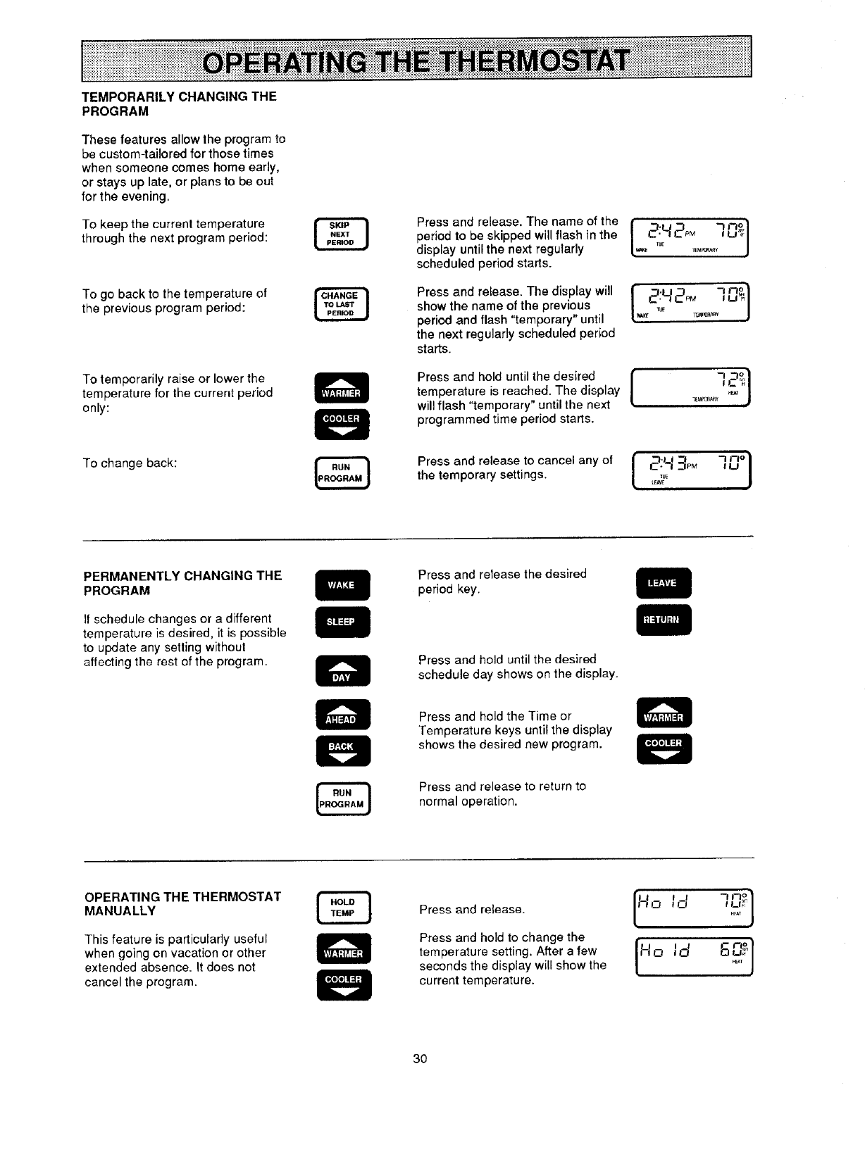
TEMPORARILY CHANGING THE
PROGRAM
These features allow the program to
be custom-tailored for those times
when someone comes home early,
or stays up late, or plans to be out
for the evening.
To keep the current temperature
through the next program period:
To go back to the temperature of
the previous program period:
Press and release. The name of the
period to be skipped will flash in the
display until the next regularly
scheduled period starts.
Press and release. The display will
show the name of the previous
period and flash "temporary" until
the next regularly scheduled period
starts.
IPaPOPA_¥
I _.u_ 7n_I
To temporarily raise or lower the
temperature for the current period
only:
Press and hold until the desired [
temperature is reached. The display t
will flash "temporary" until the next
programmed time period starts.
-, _1
_EU_ _e_T J
To change back: Press and release to cancel any of {_;___pM ]_o}
the temporary settings. _,,_,_
PERMANENTLY CHANGING THE
PROGRAM
If schedule changes or a different
temperature is desired, it is possible
to update any soiling without
affecting the rest of the program•
Press and release the desired
period key.
Press and hold until the desired
schedule day shows on the display.
Press and held the Time or
Temperature keys until the display
shows the desired new program.
Press and release to return to
normal operation.
OPERATING THE THERMOSTAT
MANUALLY
This feature is particularly useful
when going on vacation or other
extended absence. It does not
cancel the program.
Press and release.
Press and hold to change the
temperature setting. After a few
seconds the display will show the
current temperature.
"_n° I
It ! I
30
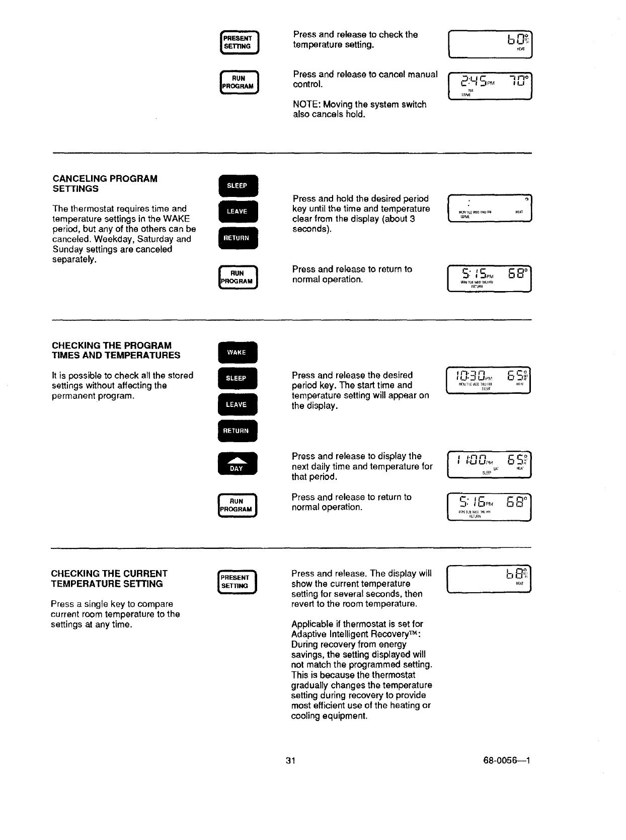
Press and release to check the
temperature setting.
Press and release to cancel manual
control.
NOTE: Moving the system switch
also cancels hold.
CANCELING PROGRAM
SE'nINGS
The thermostat requires time and
temperature settings in the WAKE
period, but any of the others can be
canceled. Weekday, Saturday and
Sunday settings are canceled
separately.
Press and hold the desired period
key until the time and temperature
clear from the display (about 3
seconds).
Press and release to return to
normal operation.
[ °]
M_ _u_WE_r_u_ HF_
L_
S: 8,-°,°]
CHECKING THE PROGRAM
TIMES AND TEMPERATURES
It is possible to check all the stored
settings without affecting the
permanent program.
Press and release the desired
period key. The start time and
temperature setting will appear on
the display.
"-' S
I I_1",.._ UPM .E',_ J
..........22;'
Press and release to display the
next daily time and temperature for
that period.
Press and release to return to
normal operation.
l
I'LJ UPMs_ '
SL_
CHECKING THE CURRENT
TEMPERATURE SETTING
Press a single key to compare
current room temperature to the
settings at any time.
Press and release. The display will |
show the current temperature [
setting for several seconds, then
revert to the room temperature.
Applicable if thermostat is set for
Adaptive Intelligent Recovery_:
During recovery from energy
savings, the setting displayed will
not match the programmed setting.
This is because the thermostat
gradually changes the temperature
setting during recovery to provide
most efficient use of the heating or
cooling equipment.
31 68-0056--1
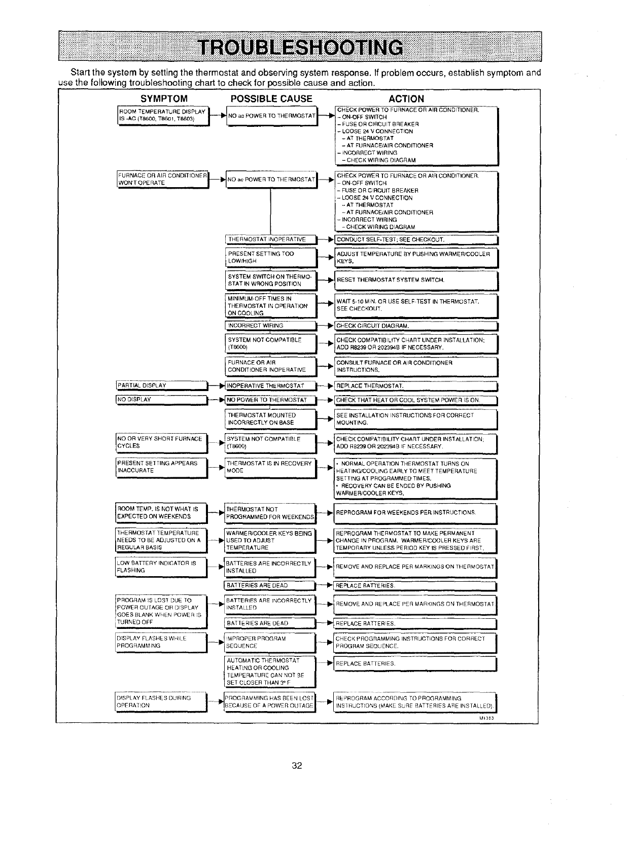
Startthesystembysettingthethermostatandobservingsystemresponse.Ifproblemoccurs,establishsymptomand
usethefollowingtroubleshootingcharttocheckforpossiblecauseandaction.
SYMPTOM POSSIBLE CAUSE ACTION
[ROOM TEMPE RATU RE DISPLAY i__ _ _I CHECK POWER TO FURNACE OR AIR CONDITION ER"
NO ac POWER TO THERMOSTAT - ON-OFF SWITCH
IS -AC (T8600, TB601, T8609) - FUSE OR CIRCUIT BREAKER
- OOSE 24 V CONNECTION
-AT THERMOSTAT
-ATFURNACE/AIR CONDITIONER
-iNCORRECT WIRING
-CHECK WIRING DIAGRAM
[_ Ft_tNO ac POWER TO THERMOSTATi_- [ ON OFF SWITH "
FURNACE OR AIR ] FUSE OR ClRcCuIT BREAKER
CONDITIONER CHECK POWER TO FURNACE OR AIR CONDITIONER
ON'T OPERATE
J- LOOSE 24 VCONNECTION
-AT THERMOSTAT
- AT FURNACEJAIR CONDITIONER
- INCORRECT WIRING
- CHECK WIRING DIAGRAM
[ THERMOSTAT INOPERATIVE t_I_[CONOtJ CT SELF-TEST; BBE CI4ECKOUT.
PRESENT SETTING TOO _[ADJUST ]EMPERATLIRE _Y PUSHING WARMER/COOLER
LO_,HIGH I "I*EYS"
f
I SYSTEM SWITCh4 ON THE RMO- _{ RESET THERMOSTAT SYSTEMSWITCN'STATIN WRONG POSITION
?Ii r
ON COOLING I_-_/
MINIMUM-OFF TIMES IN WAIT 5-10 MIN. OR USE SELF TEST IN THERMOSTAT,
THERMOSTAT iN OPERATION SEE CHECKOUT.
/£
[INCORRECT WIRING
J SYSTEM NOT COMPATIBLE
(T8600)
L
J FURNACE OR AIRCONDITIONER INOPERATIVE
_[CHECK CIRCUIT DIAGRAM, I
IPART,ALDISPLAY _ INOPERATIVE THE RMOSTA-T--_I--_ RE'PLACE THERMOSTAT. i
{NOOISPLAY i-- NO OWERTOT.E.MOSTATi---* C.EOKT.AT.EATOROOOLSYBTEMPOW RISO.|
ITNHcEoRRMROE%TTAL_%_L _NATsE?_[SEEI "L MOUNTING'INSTALLATION INSTRUCTION_ FOR CORRECT i
NyOoORVERY SHORT FURNACE II"'bJ SYSTEM NOT COMPATIBL E(T8600, r 'E%T . : 'NSTALLATON:i
IPR%Sc%NRTAST_tT INS A P PE A R S _{" TMI4rl)F_ OS TA T I_ IN R EC 0 M ERY _'l N ENAO['RNM_tLO;t ta_TIEaNRT: _%%OESE' TA; ETMUpRENRaONR E i_)i_?G IE/ICT_)iC iii yi_s=D EDT ,BMyEpSUS H [N G
EXPECTED ON WEEKENDS THERMOSTAT NOT REPI_OGRAM FOR WEEKENDS PER INSTRUCTIONS I
NEEDS TO BE ADJUSTED ON A ...... USED TO ADJUST CHANGE IN PROGRAM. WARMER/COOLER KEYS ARE
REGULAR BASIS TEMPERATURE TEMPORARY UNLESS PERIOD KEY IS PRESSED FIRST.
[LELOA%BIANqTERYINDICATOR IS /'1'NsTALLEDi_IIJRATTERIESAREINO°RREOTLY_RE_OVEANDREPLACEPERMARKtN_SONT.ER_OSTA_I
BATTERIES ARE DEAD i_" RIP'LACE BATTERIES. _1
POwERPROGRAMIS LOB] DUETOOUTAGE OR DISPLAY _BATTER_FS ARE INCORRECTLY I1-" I ¢ i
INSTALL_ "-_-I1_ I REMOVE AND REPLACE P_R MARKINGS ON THERMOSTAT
GOESBLANK WHEN POWER S
AU TQMATIC THE RMOSTAT I _ REPLACE BATTERIES"
HE AT[NG OR COOLING _ i
TEMPERATURE CAN NOT BE
SET CLOSER THAN 3° F
Mt353
32
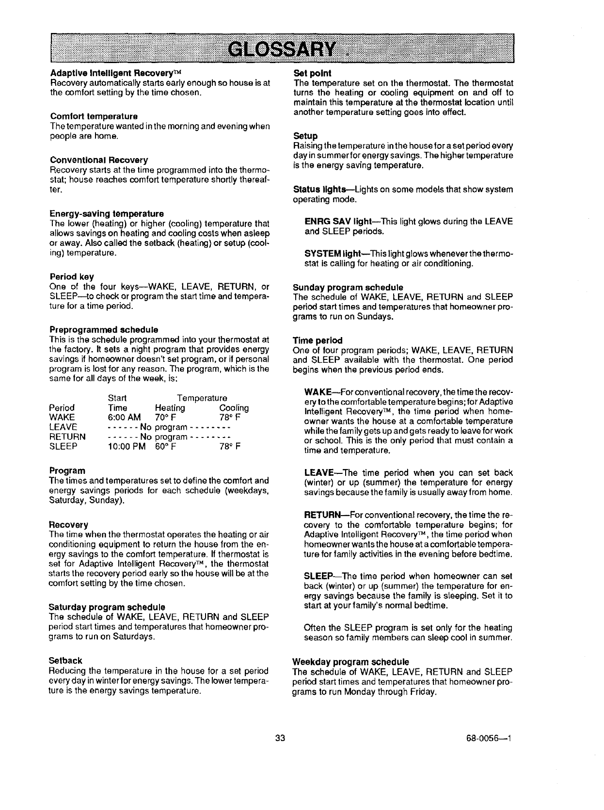
Adaptive Intelligent Recovery TM
Recovery automatically starts early enough so house is at
the comfort setting by the time chosen.
Comlort temperature
The temperature wanted in the morning and evening when
people are home.
Conventional Recovery
Recovery starts at the time programmed into the thermo-
stat; house reaches comfort temperature shortly thereaf-
ter.
Energy-saving temperature
The lower (heating) or higher (cooling) temperature that
allows savings on heating and cooling costs when asleep
or away. Also called the setback (heating) or setup (cool-
ing) temperature.
Period key
One of the four keys--WAKE, LEAVE, RETURN, or
SLEEP--to check or program the start time and tempera-
ture for a time period.
Preprogrammed schedule
This is the schedule programmed into your thermostat at
the factory. It sets a night program that provides energy
savings if homeowner doesn't set program, or if personal
program is lost for any reason. The program, which is the
same for all days of the week, is:
Start Temperature
Period Time Heating Cooling
WAKE 6:00 AM 70°F 78° F
LEAVE ...... No program ........
RETURN ...... No program ........
SLEEP 10:00 PM 60 ° F 780 F
Set point
The temperature set on the thermostat. The thermostat
turns the heating or cooling equipment on and off to
maintain this temperature at the thermostat location until
another temperature setting goes into effect.
Setup
Raising the temperature in the house for a set period every
day in summer for energy savings. The higher temperature
is the energy saving temperature.
Status lights---Lights on some models that show system
operating mode.
ENRG SAV light--This light glows during the LEAVE
and SLEEP periods.
SYSTEM light--This light glows whenever the thermo-
stat is calling for heating or air conditioning.
Sunday program schedule
The schedule of WAKE, LEAVE, RETURN and SLEEP
period start times and temperatures that homeowner pro-
grams to run on Sundays.
Time period
One of four program periods; WAKE, LEAVE, RETURN
and SLEEP available with the thermostat. One period
begins when the previous period ends.
WA KE_For conventional recovery, the time the recov-
ery to the comfortable temperature begins; for Adaptive
Intelligent Recovery TM, the time period when home-
owner wants the house at a comfortable temperature
while the family gets up and gets ready to leave for work
or school. This is the only period that must contain a
time and temperature.
Program
The times and temperatures set to define the comfort and
energy savings periods for each schedule (weekdays,
Saturday, Sunday).
Recovery
The time when the thermostat operates the heating or air
conditioning equipment to return the house from the on-
orgy savings to the comfort temperature. If thermostat is
set for Adaptive Intelligent Recovery TM, the thermostat
starts the recovery period early so the house will be at the
comfort setting by the time chosen.
Saturday program schedule
The schedule of WAKE, LEAVE, RETURN and SLEEP
period start times and temperatures that homeowner pro-
grams to run on Saturdays.
LEAVE--The time period when you can set back
(winter) or up (summer) the temperature for energy
savings because the family is usually away from home.
RETURN--For conventional recovery, the time the re-
covery to the comfortable temperature begins; for
Adaptive Intelligent Recovery TM, the time period when
homeowner wants the house at acomfortable tempera-
ture for family activities inthe evening before bedtime.
SLEEP--The time period when homeowner can set
back (winter) or up (summer) the temperature for en-
ergy savings because the family is sleeping. Set itto
start at your family's normal bedtime.
Often the SLEEP program is set only for the heating
season so family members can sleep cool in summer.
Setback
Reducing the temperature in the house for a set period
every day in winter lor energy savings. The lower tempera-
ture is the energy savings temperature.
Weekday program schedule
The schedule of WAKE, LEAVE, RETURN and SLEEP
period start times and temperatures that homeowner pro-
grams to run Monday through Friday.
33 68-0056--1
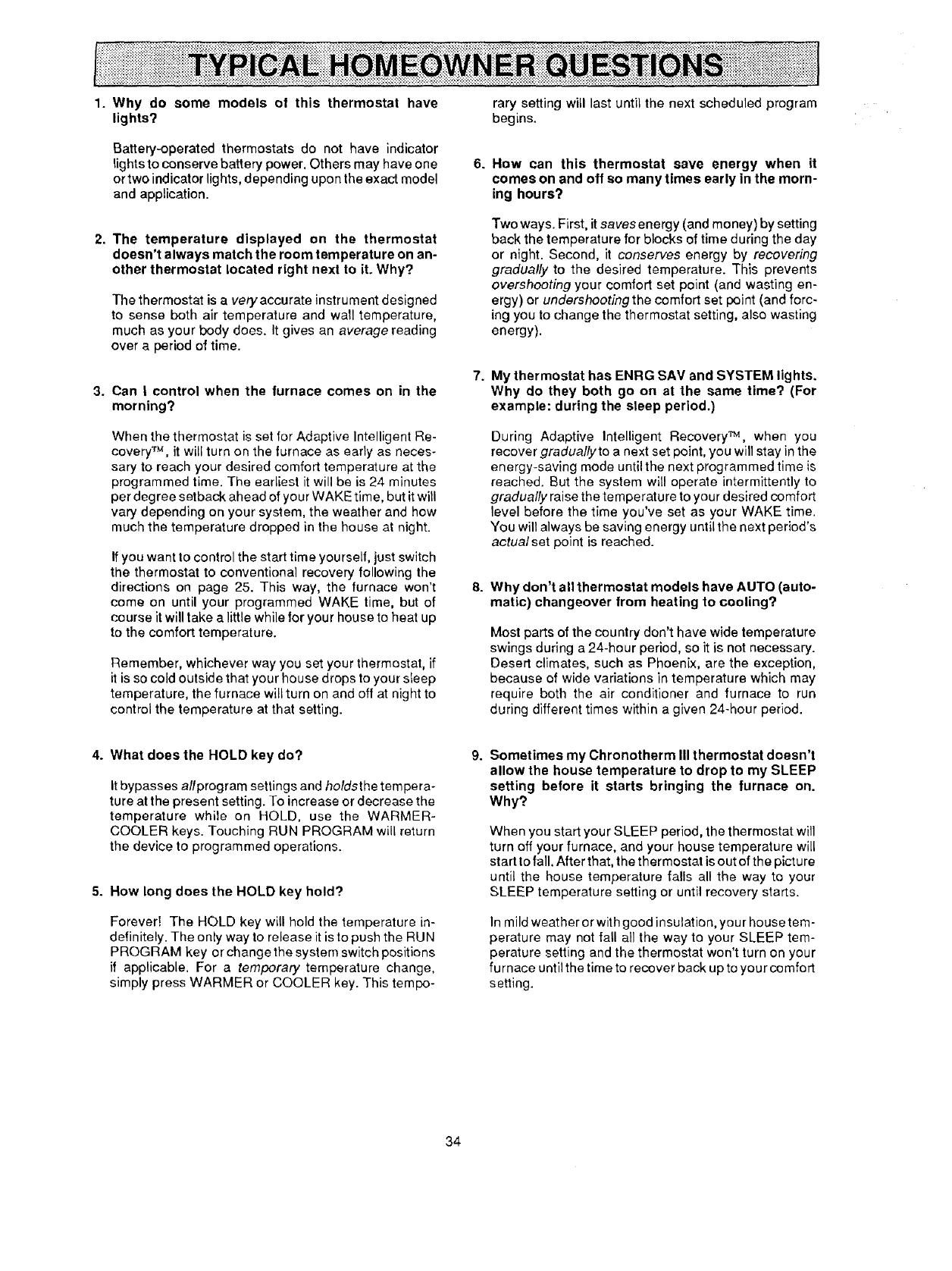
1. Why do some models of this thermostat have
lights?
Battery-operated thermostats do not have indicator
tights to conserve battery power, Others may have one
ortwo indicator lights, depending upon the exact model
and application.
2. The temperature displayed on the thermostat
doesn't always match the room temperature on an-
other thermostat located right next to it. Why?
The thermostat is avery accurate instrument designed
to sense both air temperature and wall temperature,
much as your body does. It gives an average reading
over a period of time.
3. Can Icontrol when the turnace comes on in the
morning?
When the thermostat is set for Adaptive Intelligent Re-
covery TM, it will turn on the furnace as early as neces-
sary to reach your desired comfort temperature at the
programmed time. The earliest it will be is 24 minutes
per degree setback ahead of your WAKE time, but it will
vary depending on your system, the weather and hew
much the temperature dropped in the house at night.
If you want to control the start time yourself, just switch
the thermostat to conventional recovery following the
directions on page 25. This way, the furnace won't
come on until your programmed WAKE time, but of
course it will take alittle while for your house to heat up
to the comfort temperature.
Remember, whichever way you set your thermostat, if
it is so cold outside that your house drops to your sfeep
temperature, the furnace will turn on and off at night to
control the temperature at that setting.
6.
7.
8°
rary setting will last until the next scheduled program
begins.
How can this thermostat save energy when it
comes on and off so many times early in the morn-
ing hours?
Two ways. First, it savesenergy (and money) by setting
back the temperature for blocks of time during the day
or night. Second, it conserves energy by recovering
gradually to the desired temperature. This prevents
overshooting your comfort set point (and wasting en-
ergy) or undershooting the comfort set point (and forc-
ing you to change the thermostat setting, also wasting
energy).
My thermostat has ENRG SAM and SYSTEM lights.
Why do they both go on at the same time? (For
example: during the sleep period.)
During Adaptive Intelligent Recovery TM, when you
recover graduallyto a next set point, you will stay in the
energy-saving mode until the next programmed time is
reached. But the system will operate intermittently to
gradually raise the temperature to your desired comfort
level before the time you've set as your WAKE time.
You will always be saving energy until the next period's
actual set point is reached.
Why don't all thermostat models have AUTO (auto-
matic) changeover from heating to cooling?
Most parts of the country don't have wide temperature
swings during a 24-hour period, so it is not necessary.
Desert climates, such as Phoenix, are the exception,
because of wide variations in temperature which may
require both the air conditioner and furnace to run
during different times within a given 24-hour period.
4. What does the HOLD key do?
It bypasses allprogram settings and holdsthe tempera-
ture at the present setting. To increase or decrease the
temperature while on HOLD, use the WARMER-
COOLER keys. Touching RUN PROGRAM will return
the device to programmed operations.
5. How long does the HOLD key hold?
Forever! The HOLD key will hold the temperature in-
definitely. The only way to release it is to push the RUN
PROGRAM key or change the system switch positions
if applicable. For a temporary temperature change,
simply press WARMER or COOLER key. This tempo-
Sometimes my Chronotherm III thermostat doesn't
allow the house temperature to drop to my SLEEP
setting before it starts bringing the furnace on.
Why?
When you start your SLEEP period, the thermostat will
turn off your furnace, and your house temperature will
start to fall. After that, the thermostat is out of the picture
until the house temperature falls all the way to your
SLEEP temperature setting or until recovery starts.
In mild weather or with good insulation, you r house tem-
perature may not fall all the way to your SLEEP tem-
perature setting and the thermostat won't turn on your
furnace until the time to recover back up to your comfort
setting.
34
page
SPECIFICATIONS ............................................................................................................................................................ 2
ORDERING INFORMATION ............................................................................................................................................ 2
INSTALLATION ................................................................................................................................................................4
Compatibility...............................................................................................................................................................4
Location.......................................................................................................................................................................4
Mounting Wallplate ....................................................................................................................................................4
Wiring ..........................................................................................................................................................................5
Cycle Rate AdJustment............................................................................................................................................20
Adaptive Intelligent RecoveryT_/ConventionalRecovery Conversion ................................................................20
Time/Temperature Conversion (Some Models) ..................................................................................................... 20
Fan Operation Switch...............................................................................................................................................20
Installing Batteries ...................................................................................................................................................21
Mounting the Thermostat ........................................................................................................................................ 21
Setting Day end Time ............................................................................................................................................... 21
CHECKOUT .................................................................................................................................................................... 22
Heating ...................................................................................................................................................................... 22
Cooling ...................................................................................................................................................................... 22
Fan ............................................................................................................................................................................. 23
Installer Self-Test (optional) .................................................................................................................................... 23
ABOUT ADAPTIVE INTELLIGENT RECOVERY TM ....................................................................................................... 24
RECOVERY SETTING PROCEDURE ............................................................................................................................ 24
PROGRAMMING THE THERMOSTAT .......................................................................................................................... 25
Set the Current Day and Time ................................................................................................................................. 25
Set the Program Schedule and Heating Temperatures ........................................................................................ 25
Set the Cooling Temperatures ................................................................................................................................ 27
Set the System and Fan Switches .......................................................................................................................... 29
OPERATING THE THERMOSTAT ................................................................................................................................. 30
Temporarily Changing the Program ....................................................................................................................... 30
Permanently Changing the Program ...................................................................................................................... 30
Operating the Thermostat Manually ....................................................................................................................... 30
Canceling Program Settings ................................................................................................................................... 31
Checking the Program Times and Temperatures ................................................................................................. 31
Checking the Current Temperature Setting ........................................................................................................... 31
TROUBLESHOOTING .................................................................................................................................................... 32
GLOSSARY .................................................................................................................................................................... 33
TYPICAL HOMEOWNER QUESTIONS ......................................................................................................................... 34
This equipment is a Class B digital apparatus which corn plies with Canadian Radio Interference Regulations, CRC c. 1374.
35 68-0056--1

Honeywell Inc.
1885 Douglas Drive N.
Golden Valley, MN 55422-4386
I
International Sales Offices in all principal cities of the world. Manufacturing in ]
Australia, Canada, Finland, France, Germany, Japan, Mexico, Netherlands, I
Spain, Taiwan, United Kingdom, U.S.A. PRINTED IN U.S.A, QUALITY IS KEY
