User manual
1/12
User
UserUser
User's
's's
's
Manual
ManualManual
Manual
P
PP
Preparation day
reparation day reparation day
reparation day :
::
:
30/June/2009
30/June/200930/June/2009
30/June/2009
Product Name
Product NameProduct Name
Product Name
:
::
:WIRELESS
WIRELESSWIRELESS
WIRELESS
MODULE
MODULEMODULE
MODULE
Model Name
Model NameModel Name
Model Name
:
::
:1500
15001500
1500#
##
#00
0000
00-
--
-A
AA
A
(
((
(Model Number
Model NumberModel Number
Model Number)
))
)

2/14
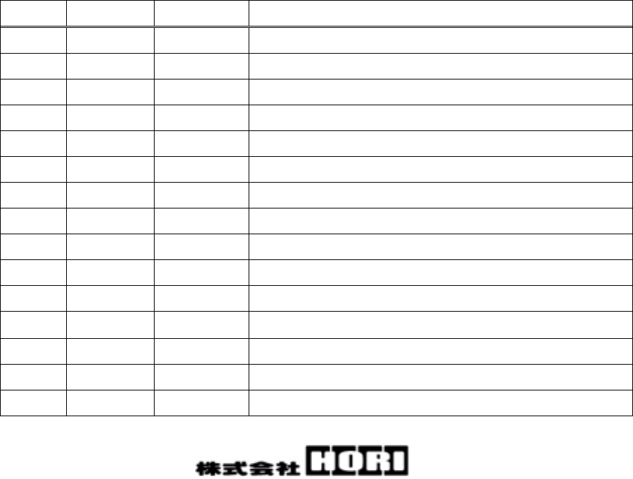
Revision hysteresis.
Date Edition number Revision content Writer
30/July/2009 First version First version publication T.Ogawa

3/14
■On safety design
Though our company has paid close attention to quality, semi-conductive products
can malfunction and fail.
Our company has gone to great lengths to create a safe product which does not cause
any injury accidents, fire accidents, public harm, etc., and incorporated safety
features such as fire prevention and malfunction prevention into our design.
■On exemption from obligatory matter
The company is not responsible for damages resulting from natural disaster,
actions by a third person and other accidents, deliberate misuse or negligence
by the customer, and damages due to abnormal use.
The company is not responsible for any incidental damage caused by our product
(loss of business, loss of the business profit, loss and/or changes in memory
content, etc. ).
The company is not responsible for all other damages caused through failure to
abide by the description of this material.
The company is not responsible for damages resulting from connection with
equipment or combination with the software for which we are not concerned with.
Finally, our company is not responsible for damages resulting from error from this
material.
■On equipment certification
Following matters may be punishable by law:
・ If any modification is made to this product.
・ If the silk printing on the product is removed.

4/14
Contents
1.Application range 5
2.General specification 6
3.Usage 8
4.Radio specification 10
5.Precautions for each standard 11
6.Requirements to end product 13

5/14
1.Application range
1-1 Application
This specification is applied to the following.
Product Name: WIRELESS MODULE
Model Name : 1500#00-A
(Model Number)
1-2 Applicable with
Sony Computer Entertainment 『Playstation3』
※1500#00-A is a radio module.
This is a transceiver module and requires it to be placed within an
external input device to operate.
It must be used with model number 1500#00-B as a set.
1-3 Application standard
・ Wireless Telegraphy Act Article 38 Section 2 - 1 - 19
・ FCC Part15 Subpart C
・ EN300 328
※This module meets the CE mark requirements.
However, it is advised that the external input device be re-examined for
compatibility after the module is mounted.
6/14
2.General specification
2-1 Shape and dimension
Dimension : Approximately 30mm× 39mm× 12mm
Mass : About 8g
2-2 Operational temperature and humidity range (In operation)
Temperature : 0℃∼+40℃
Humidity : 20∼25%RH
(Assuming there is no dew condensation.)
2-3 Storage temperature and humidity range (In storage)
Temperature : -25℃∼+60℃
Humidity : 20∼85%RH
(Assuming there is no dew condensation.)
2-4 Function
This product is a radio module.
It is necessary to set an external controller and use with 1500#00-B
as a set.
By setting the unit, the controller becomes operational with the Sony
Computer Entertainment『Playstation3』.
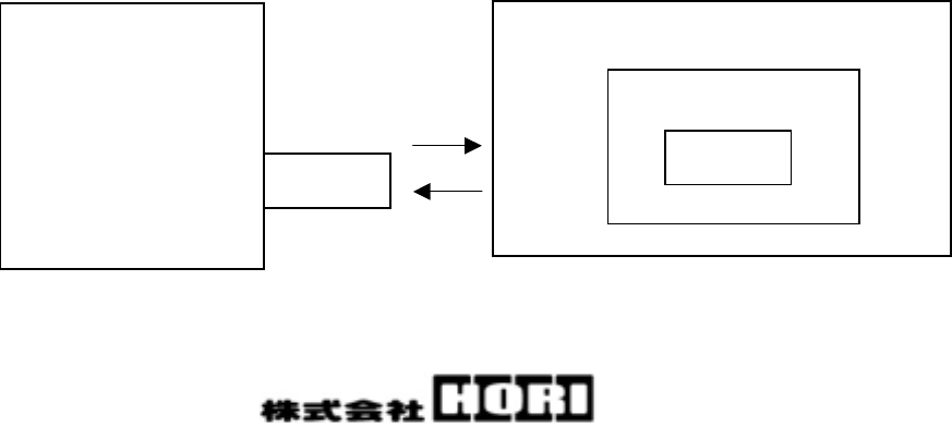
2-5 System constitution
Set to an external controller.
Main PCB
Controller
Playstation3
1500#00-B 1500#00-A
7/14
2-6 Connection unit number
1500#00-B communicates one-to-one with 1500#00-A.
A maximum 7 sets of 1500#00-A and 1500#00-B, can be connected to one
『Playstation3』.
Also, in the presence of multiple『Playstation3』, a maximum 25 sets of
1500#00-A and 1500#00-B can be connected simultaneously.
2-7 Power
Input voltage : DC+1.8∼3.3V(Supplied from 2 batteries)
Consumption current :5mA (In normal operation)
2-8 Communication range
The communication range of the radio communication is within 10m.
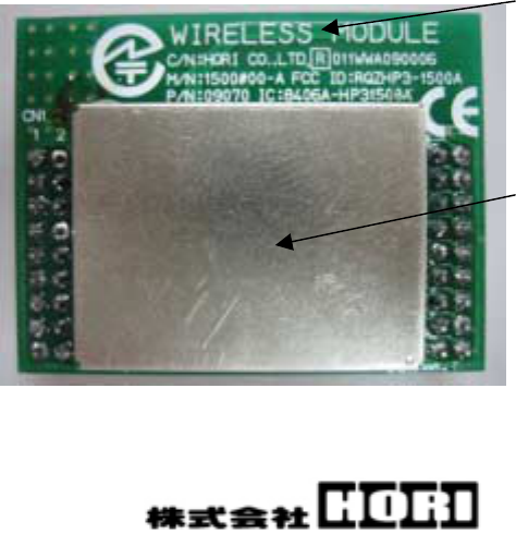
2-9 Appearance and name of each part
Antenna
Shield case
8/14
3.Usage
3-1 Connection method
① The HP3-1500A is mounted on an external device as part of the controller.
※From this point forward, the device will be referred to as controller
with 1500#00-A mounted.
② 1500#00-B is connected with the USB port of the Playstation3 console.
③ 1500#00-B communication indicator LED flashes on and off.
(Light will turn on and off every 250msec intervals.)
④ The controller with 1500#00-A mounted is supplied with power.
(DC+1.8V∼3.3V)
⑤ When controller with 1500#00-A mounted establishes communication the
communication indicator LED on the 1500#00-B either stays lit or
continues to flashes on and off.
(The flashing, in this case, occurs at every 100msec intervals.)
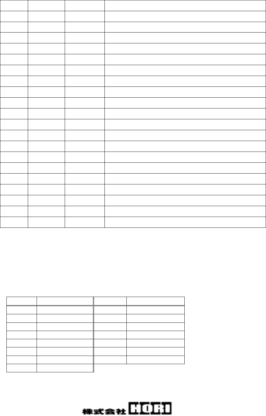
3-2 Pin layout
Pin No Setting Function
Note
1 Input VSS Power Ground(0V)
2 Input VDD Power Supply(DC+1.8V∼+3.3V)
3 Input R2 Inside pull-down Normal:Low Active:Hi
4 Input R1 Inside pull-down Normal:Low Active:Hi
5 Input L2 Inside pull-down Normal:Low Active:Hi
6 Input L1 Inside pull-down Normal:Low Active:Hi
7 Input SELECT Inside pull-down Normal:Low Active:Hi
8 Input START Inside pull-down Normal:Low Active:Hi
9 Input − It is not used.
10 Input − It is not used.
11 Output − It is not used.
12 Output − It is not used.
13 Input − It is not used.
14 Input − It is not used.
15 Input − It is not used.
9/14
16 Input PROG It is not used.
17 Input − It is not used.
18 Input VSS Power Ground(0V)
19 Input RESET Normal:Hi Active:Low
20 Input ○ Inside pull-down Normal:Low Active:Hi
21 Input □ Inside pull-down Normal:Low Active:Hi
22 Input × Inside pull-down Normal:Low Active:Hi
23 Input RIGHT Inside pull-down Normal:Low Active:Hi
24 Input UP Inside pull-down Normal:Low Active:Hi
25 Input LEFT Inside pull-down Normal:Low Active:Hi
26 Input DOWN Inside pull-down Normal:Low Active:Hi
27 Output CSN It is not used.
28 Input PS Inside pull-down Normal:Low Active:Hi
29 Output MISO It is not used.
30 Input △ Inside pull-down Normal:Low Active:Hi
31 Output − It is not used.
32 Output MOSI It is not used.
33 Output SCK It is not used.
34 Output − It is not used.
35 Input BMO Battery monitoring
36 Input − It is not used.
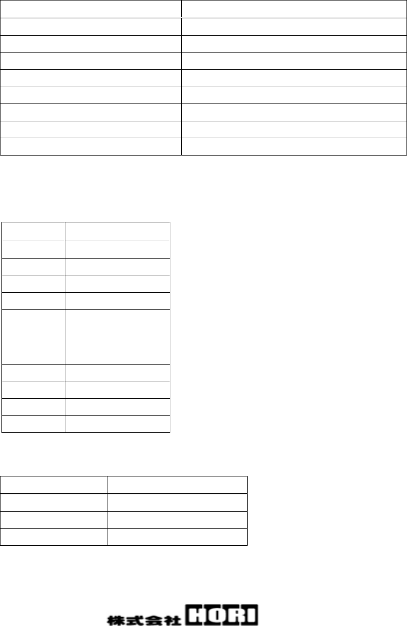
3-3 Sleep function
If below parts are not active for 3 minutes, the product will enter sleep mode.
In the sleep mode, energy consumption will be minimized.
Pin No Function Pin No Function
3 R2 22 ×
4 R1 23 RIGHT
5 L2 24 UP
6 L1 25 LEFT
7 SELECT 26 DOWN
8 START 28 PS
20 ○ 30 △
21 □
If any of the above port becomes active, the controller will return from sleep mode.
10/14
4.Radio specification
4-1 General specification
Parameter Value/Note
Modulation system GFSK
Spectrum diffusion process Frequency hopping
Number of channels 25ch
Frequency range 2405MHz∼2477MHz
IC transmission output 0dBm[Max.]
Data rate 1Mbps[Max.]
Rock crystal vibrator frequency
16MHz
Operating voltage DC+1.8V∼3.3V(Supply from 2 batteries.)
4-2 Channel frequency
Channel Frequency [MHz]
1 2405
2 2408
3 2411
4 2414
・
・
・
・
22 2468
23 2471
24 2474
25 2477
4-2 Antenna
Parameter Value/Note
Type Monopole antenna
Composition Pattern antenna
Gain -0.08 dBi[Max.]

11/14
5.Precautions for each standard
5-1 FCC ClassB
CAUTION:
Any changes or modifications not expressly approved by the party responsible
for compliance could void the user's authority to operate the equipment.
NOTE: This equipment has been tested and found to comply with the limits for
a Class B digital device, pursuant to part 15 of the FCC Rules. These limits
are designed to provide reasonable protection against harmful interference
in a residential installation. This equipment generates, uses and can
radiate radio frequency energy and, if not installed and used in accordance
with the instructions, may cause harmful interference to radio communications.
However, there is no guarantee that interference will not occur in a
particular installation. If this equipment does cause harmful interference
to radio or television reception, which can be determined by turning the
equipment off and on, the user is encouraged to try to correct the interference
by one or more of the following measures:
—Reorient or relocate the receiving antenna.
—Increase the separation between the equipment and receiver.
—Connect the equipment into an outlet on a circuit different from that to
which the receiver is connected.
—Consult the dealer or an experienced radio/TV technician for help.
5-2 FCC (15.19) /IC(RSS-210 Low Power Device)
Operation is subject to the following two conditions: (1) this device may
not cause interference, and (2) this device must accept any interference,
including interference that may cause undesired operation of the device.

12/14
5-3 IC and FCC(Radio)
RF exposure compliance
1) To comply with FCC/IC RF exposure compliance requirements, a separation
distance of at least 20 cm must be maintained between the antenna of this
device and all persons.
2) This transmitter must not be co-located or operating in conjunction with
any other antenna or transmitter.

13/14
6.Requirements to end product
This module must be integrated only by OEM integrators under the following
conditions.
(1) OEM integrator has to be aware not to provide information to the users
regarding how to install or remove this module in the user’s manual of the end
product which integrate this module. Installation by end users is strictly
prohibited.
(2) Antenna
OEM integrator shall use this module without any modifications including antenna.
If module integrator uses a unique antenna, the FCC certification is required
for the end product.
OEM integrator must make sure that 20cm minimum separation is maintained between
users and the antenna.
(3) Co-location.
This module must not be co-located or operated in conjunction with any other
antenna or transmitter. The module integrator shall obtain FCC approval for the
end product, if the module is used for co-location operation.
(4) Markings
To satisfy FCC/IC exterior labeling requirements, the following text must be
placed on the exterior of the end product.
Contains Module FCC ID: RQZHP3-1500A, IC: 8406A-HP31500A
Any similar wording that expresses the same meaning may be used.
(5) Caution to user for modification
The following caution is expressed on the user’s instruction manual.
The changes or modifications not expressly approved by the party responsible for
compliance could void the user’s authority to operate the device.

14/14
(6) Compliance statement to FCC
NOTE: This equipment has been tested and found to comply with the limits for a
Class B digital device, pursuant to part 15 of the FCC Rules. These limits are
designed to provide reasonable protection against harmful interference in a
residential installation. This equipment generates uses and can radiate radio
frequency energy and, if not installed and used in accordance with the
instructions, may cause harmful interference to radio communications. However,
there is no guarantee that interference will not occur in a particular
installation. If this equipment does cause harmful interference to radio or
television reception, which can be determined by turning the equipment off and
on, the user is encouraged to try to correct the interference by one or more of
the following measures:
—Reorient or relocate the receiving antenna.
—Increase the separation between the equipment and receiver.
—Connect the equipment into an outlet on a circuit different from that to which
the receiver is connected.
—Consult the dealer or an experienced radio/TV technician for help.
(7) Compliance statement to IC
The following statement is expressed on the user’s instruction manual.
Operation is subject to the following conditions: (1) This device may not cause
harmful interference, and (2) this device must accept any interference received,
including interference that may cause undesired operation.