HOSEOTELNET ATM300 RF Module User Manual the
Hoseo Telnet Co., Ltd. RF Module the
Users Manual

ATM300
[ User manual ]
User Manual
The ReFLEX Module
(ATM 300)
Tel 02 ) 2659 - 7345
Fax 02 ) 3662 - 0973
http://www.hstelnet.com/
Tel 02 ) 2659 - 7345
Fax 02 ) 3662 - 0973
http://www.hstelnet.com/
ReFLEX Module
0/13
ReFLEX Module

ATM300
[ User manual ]
Content
1. Description
2. Outline and Function
2.1 Outline
2.2 Description of 14 pin Connector
2.3 Sub Board & Data Link Cable
2.4 Package
3. Configure the ReFLEX Module – PPS -
3.1 login
3.2 List
3.3 Control
4. Message receiving and sending
4.1 HSM8800
4.1.1 Message sending
4.1.2 Message receiving
HOW TO SET “ReFLEX” TWO WAY RADIO MODULE.
Tel 02 ) 2659 - 7345
Fax 02 ) 3662 - 0973
http://www.hstelnet.com/
Tel 02 ) 2659 - 7345
Fax 02 ) 3662 - 0973
http://www.hstelnet.com/
ReFLEX Module
1/13
ReFLEX Module
ATM300
[ User manual ]
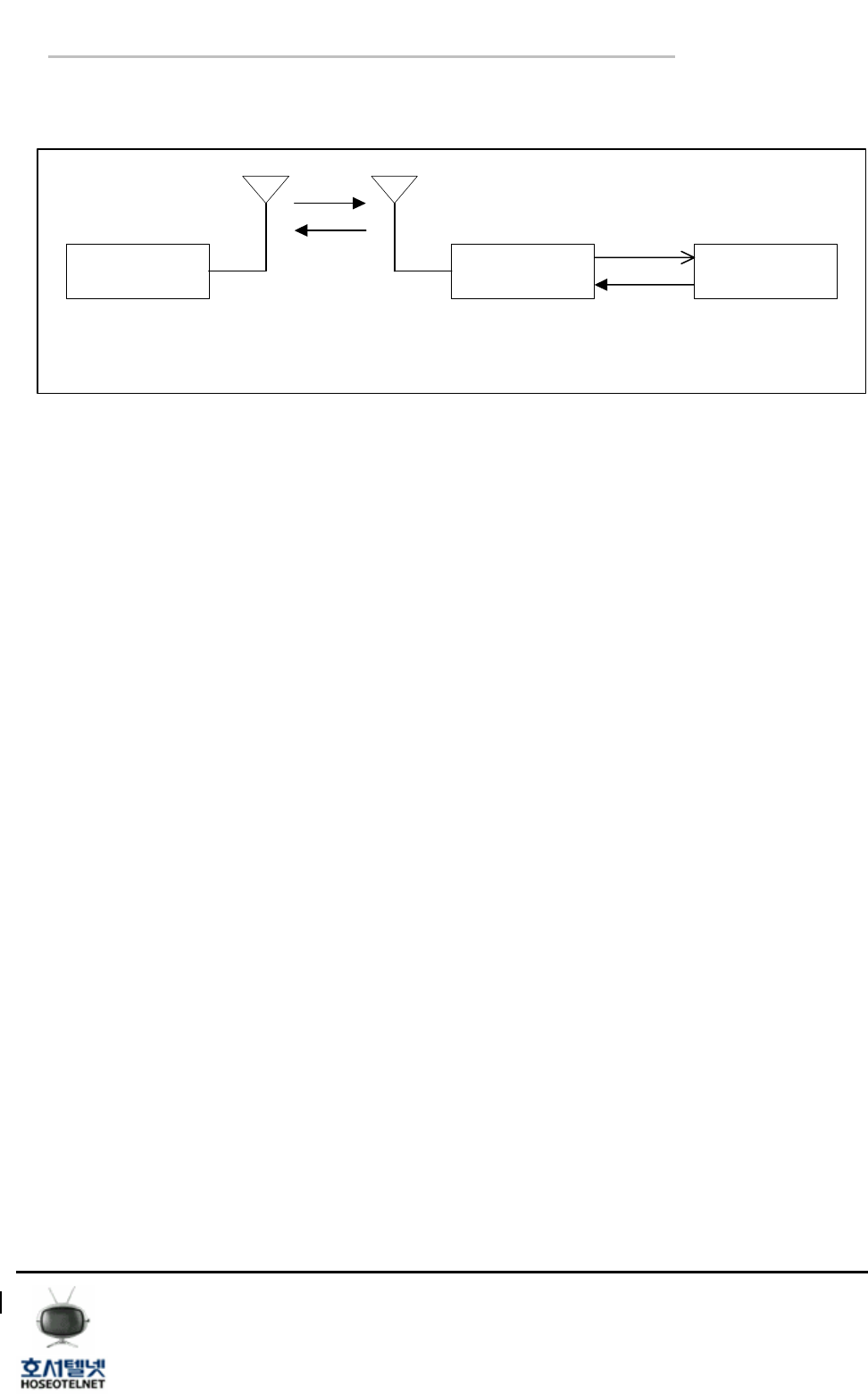
1. Description
- System Block Diagram
System ReFLEX
Module
Host
Device
ReFLEX
CLP Serial
Interface
Carrier’s
System
< Figure 1> ReFLEX system Block Diagram
- ReFLEX : The communication protocol between Carrier’s system and ReFLEX device or module
through ReFLEX network.
- CLP Serial Interface : It is communication Linking Protocol (CLP), it enable the wire
communication between ReFLEx device or module and Host device through the Serial
Interface.
● Message receiving and sending
The Message receiving and sending is possible by pc program ( HSM8800 v1.3) which
support the CLP serial interface even thought there is no Host device.
Refer to CLP reference manual for more information for serial interface of
Communication Linking Protocol (CLP).
● Configure the ReFLEX Module
The configuration of ReFLEX Module will be done by PC based program ( PPS).
Tel 02 ) 2659 - 7345
Fax 02 ) 3662 - 0973
http://www.hstelnet.com/
Tel 02 ) 2659 - 7345
Fax 02 ) 3662 - 0973
http://www.hstelnet.com/
ReFLEX Module
2/13
ReFLEX Module
ATM300
[ User manual ]
2. Outline and Function
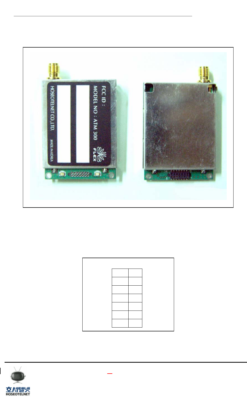
2.1 ReFLEX Module Outline
< Figure 2 > ReFLEX Module
ReFLEX Module
3/13
ReFLEX Module
The interface between ReFLEX Module and Host Device will be done by 14 pin connector.
2.2 Description of 14 pin connector
1 8
2 9
3 10
4 11
5 12
6 13
7 14
< Figure 3 > 14 pin connector
Tel 02 ) 2659 - 7345
Fax 02 ) 3662 - 0973
http://www.hstelnet.com/
Tel 02 ) 2659 - 7345
Fax 02 ) 3662 - 0973
http://www.hstelnet.com/
ATM300
[ User manual ]
2.3 Pin Configuration
PIN Name Type Description
1 VCC_Tx 4V~10V, 3A, PA Voltage
2 VCC_Main 4V~10V,200mA, Controller Voltage
3 GPIO0 CMOS, General Purpose I/O
4 GPIO1 CMOS, General Purpose I/O
5 SI0 Reserved, NC
6 SO0 Reserved, NC
7 SCK0 Reserved, NC
8 VCC Reserved, NC
9 GND Signal Ground
10 Tx_Data UART Output
11 Rx_Data UART Input
12 Enable Module Enable
13 VPP Reserved, NC
14 GND Signal Ground
*Note :CMOS Level 3V
< Table 1> Pin description
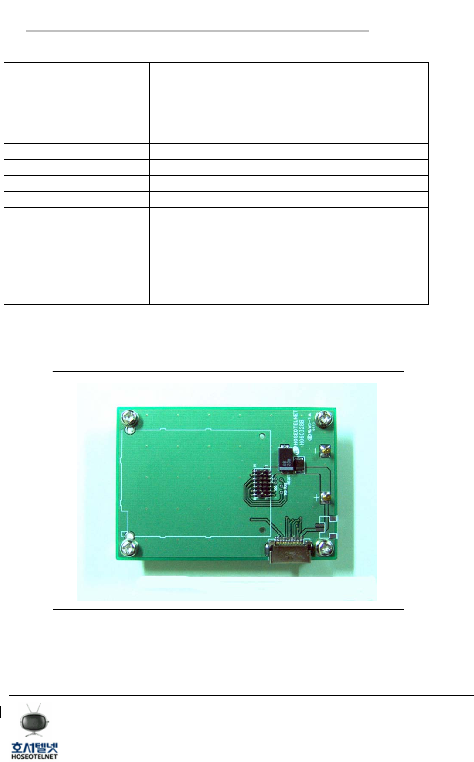
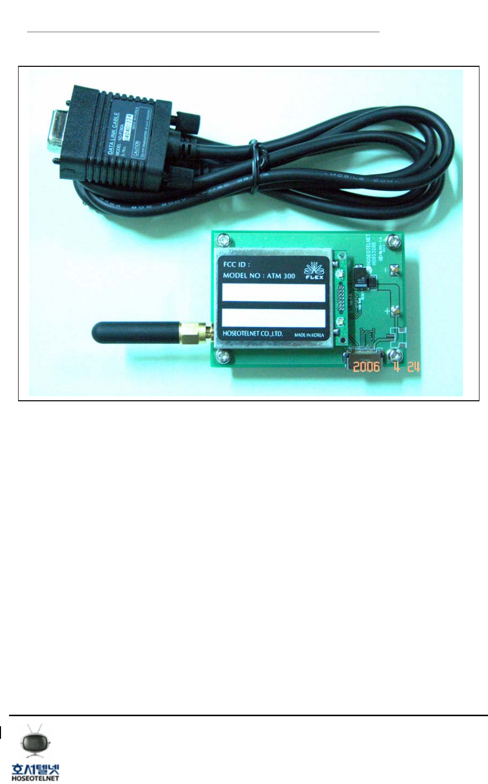
2.4 Sub Board & Data Link Cable
< Figure 4 > Sub Board
Tel 02 ) 2659 - 7345
Fax 02 ) 3662 - 0973
http://www.hstelnet.com/
Tel 02 ) 2659 - 7345
Fax 02 ) 3662 - 0973
http://www.hstelnet.com/
ReFLEX Module
4/13
ReFLEX Module
ATM300
[ User manual ]
1) Sub Board :
The sub board will supply the power to module and it will be used for parameter setting (PPS) and
data receiving and sending by PC. If you apply the DC 4-10V to power terminal, then module
will be activated.
The communication with PC will be able to by specific data link cable which supplied by module
supplier.
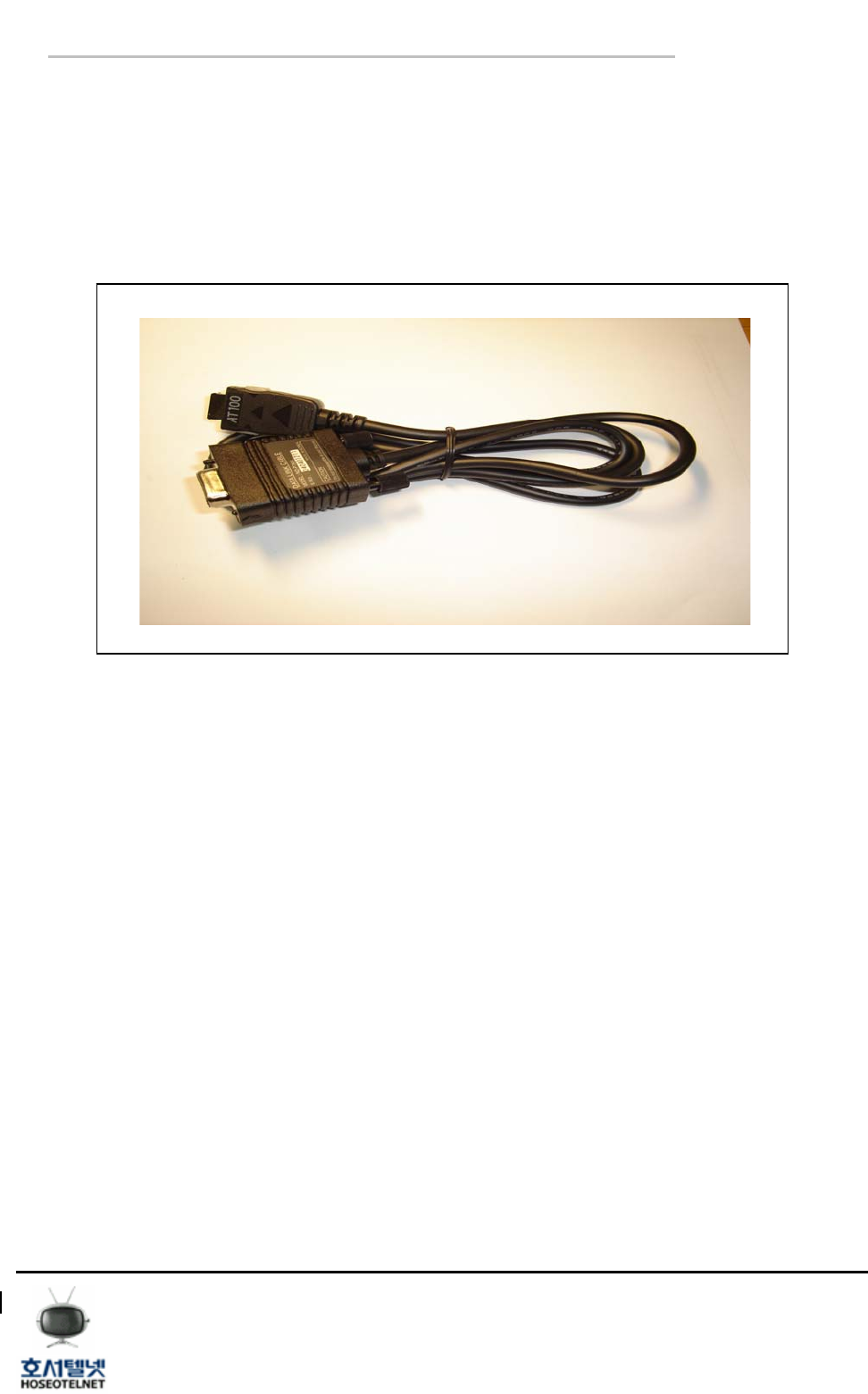
< Figure 5 > Data Link Cable
2) Data Link Cable :
It will be used for communication between ReFLEX Module and PC through Sub Board. The data
link cable, which is being supplied by ATM300 supplier, incorporated the RS232C converter, then
you can communicate with PC without additional peripherals.
Tel 02 ) 2659 - 7345
Fax 02 ) 3662 - 0973
http://www.hstelnet.com/
Tel 02 ) 2659 - 7345
Fax 02 ) 3662 - 0973
http://www.hstelnet.com/
ReFLEX Module
5/13
ReFLEX Module
ATM300
[ User manual ]
2.5 Package
< Figure 6 > Package
● Pre caution for Module(ATM 300) interface
The serial communication default speed is being set as 9600BPS, if you can change it CLP
command.
- Module (ATM 300) has a power save mode function, then you must wake up the module
whenever you are to use it. The wake up time is 20ms, and if you are to wake up the module,
send the CLP command 0x19.
- After the reset, the module will not goes to power save mode for 60 seconds, then you can
do the parameter setting during that time by PPS program.
● Module Operation Description
- If you apply the power, the LED will be On and Off.
- ‘P’ LED will be “ON” when the Module synchronized to network.
- ‘T’ LED will be “ON” when Module is transmitting a data..
- LED can be disabled by command.
Tel 02 ) 2659 - 7345
Fax 02 ) 3662 - 0973
http://www.hstelnet.com/
Tel 02 ) 2659 - 7345
Fax 02 ) 3662 - 0973
http://www.hstelnet.com/
ReFLEX Module
6/13
ReFLEX Module
ATM300
[ User manual ]
3. Configure the ReFLEX Module – PPS -
Please refer to PPS manual for more details.
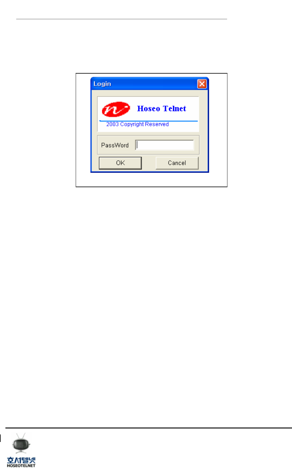
3.1 Login
< Figure 7 > Login
Key in the default password ‘HSTMAST’.
Tel 02 ) 2659 - 7345
Fax 02 ) 3662 - 0973
http://www.hstelnet.com/
Tel 02 ) 2659 - 7345
Fax 02 ) 3662 - 0973
http://www.hstelnet.com/
ReFLEX Module
7/13
ReFLEX Module
ATM300
[ User manual ]
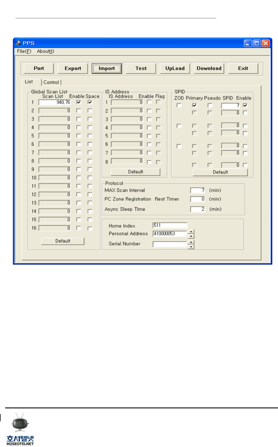
3.2 List
< Figure 8 > List
- Global Scan List : Rx frequency setting(if Space is set Spacing is 10KHz)
- IS Address : Information Service address
- SPID : Service Provide ID
- Personal Address : Cap code
- Else : refer to PPS user’s guide
- Menu Description
① Export : Store the PPS Parameter file.
② Import : Reading the PPS Parameter file.
③ Download : Download the data to ReFLEX Module.
④ Personal Address : Put in the ReFLEX Module MSN.
Tel 02 ) 2659 - 7345
Fax 02 ) 3662 - 0973
http://www.hstelnet.com/
Tel 02 ) 2659 - 7345
Fax 02 ) 3662 - 0973
http://www.hstelnet.com/
ReFLEX Module
8/13
ReFLEX Module
ATM300
[ User manual ]
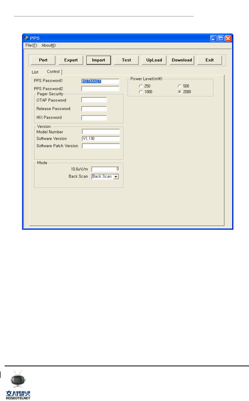
3.3 Control
< Figure 9 > Control
- Power Level(mW) : RF Power Output
- PPS password : PPS login password
Tel 02 ) 2659 - 7345
Fax 02 ) 3662 - 0973
http://www.hstelnet.com/
Tel 02 ) 2659 - 7345
Fax 02 ) 3662 - 0973
http://www.hstelnet.com/
ReFLEX Module
9/13
ReFLEX Module
ATM300
[ User manual ]
4. Message Sending and Receiving
If there is no Host device, you can send and receive the message through PC.
The firmware, HSM8800 make you to sending and receiving the message, and you can also
check the functionality of ATM300.
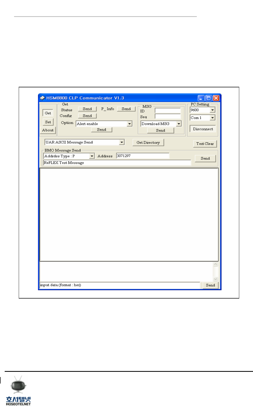
4.1 HSM8800
< Figure 10 > HSM8800 CLP Communicator v1.3
Tel 02 ) 2659 - 7345
Fax 02 ) 3662 - 0973
http://www.hstelnet.com/
Tel 02 ) 2659 - 7345
Fax 02 ) 3662 - 0973
http://www.hstelnet.com/
ReFLEX Module
10/13
ReFLEX Module
ATM300
[ User manual ]
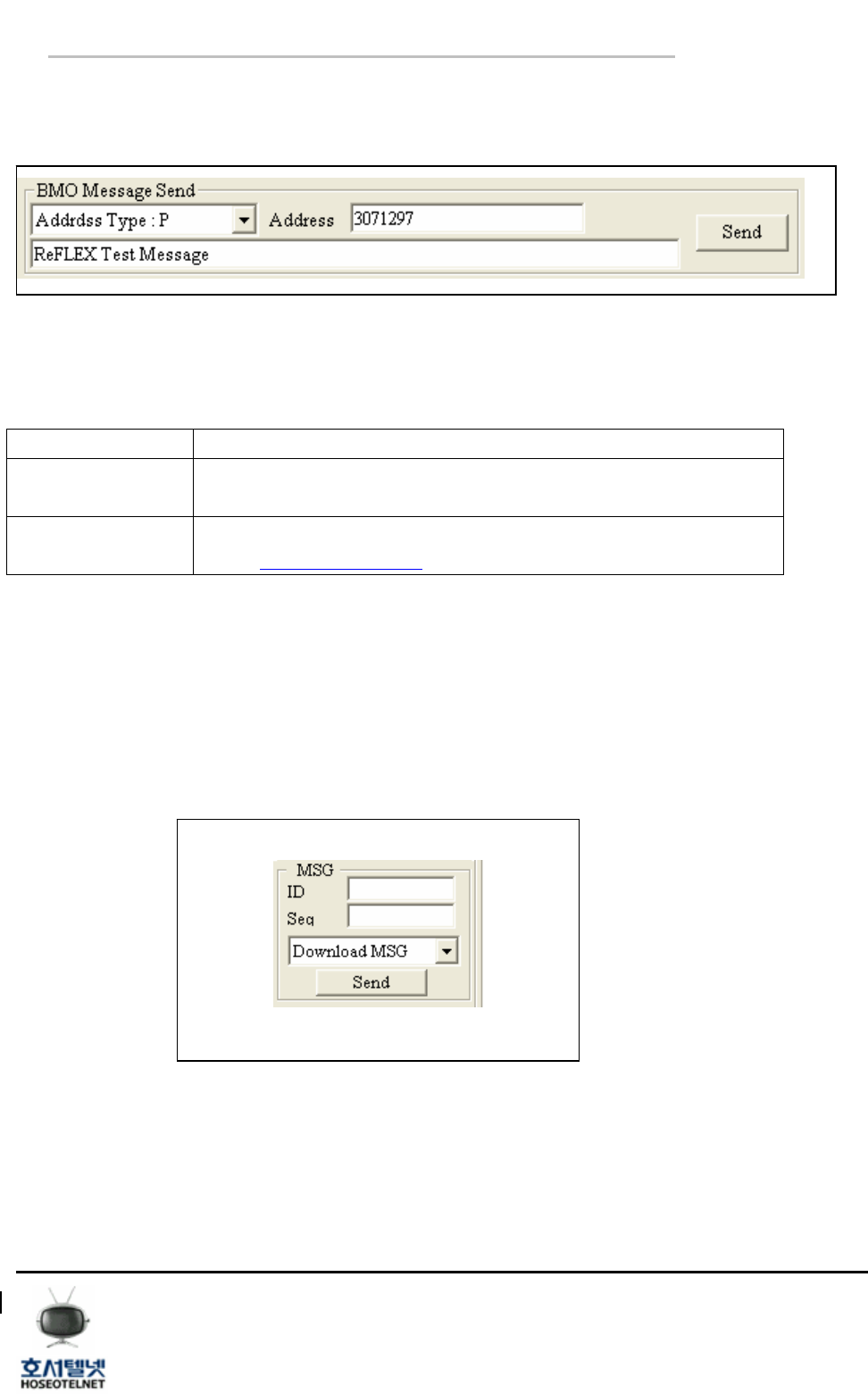
4.1.1 Message Sending
Sending the message to destination..
< Figure 11 > BMO Message Send
① Address Type : There are two(2) address type “P” and “E”
Address Type Description
P Send the message using PIN number of ReFLEX Module.
(Ex. : 3071297 )
E Sending the message using email address.
( Ex. : hjino5@hoseo.or.kr )
< Table2 > Address Type
② Address : key in the address of receiving part.
③ ReFLEX Test Message: key in the sending message.
④ Send : Click the “Send” button to send the message..
4.1.2 Message receiving
Download the received message on ReFLEX Module.
< Figure 12 > Download MSG
① Click the “Send” button to download the received message.
Tel 02 ) 2659 - 7345
Fax 02 ) 3662 - 0973
http://www.hstelnet.com/
Tel 02 ) 2659 - 7345
Fax 02 ) 3662 - 0973
http://www.hstelnet.com/
ReFLEX Module
11/13
ReFLEX Module

ATM300
[ User manual ]
HOW TO SET ReFLEX TWO WAY RADIO MODULE.
- Check the power source , 4~10V and 3A
- Soldering the Shield Case to Ground
- Connect the 50 ohm antenna to SMA connector of module
*Do not operate the module without Antenna
- Apply the power and Interface
*Remark
- Do not change the trimmer set on case
- Do not open the shield case, In this case a warranty conditions will be invalid.
“CAUTION : Exposure to Radio Frequency Radiation.
Antenna shall be mounted in such a manner to minimize the potential for human
contact during normal operation. The antenna should not be contacted during
operation to avoid the possibility of exceeding the FCC radio frequency exposure limit.
The minimum separation distance of 20cm from the antenna to the body of user
required.”
Tel 02 ) 2659 - 7345
Fax 02 ) 3662 - 0973
http://www.hstelnet.com/
Tel 02 ) 2659 - 7345
Fax 02 ) 3662 - 0973
http://www.hstelnet.com/
ReFLEX Module
12/13
ReFLEX Module