HP Office Jet C2890A All In One (English) Technical Support Solutions Guide Bpu00279
User Manual: HP HP OfficeJet C2890A All-in-One - (English) Technical Support Solutions Guide
Open the PDF directly: View PDF ![]() .
.
Page Count: 175 [warning: Documents this large are best viewed by clicking the View PDF Link!]
HP OfficeJet Family
Technical Support Solutions Guide

vii
Contents
Subject Page
Chapter 1: Product Information
Introduction 1-2. . . . . . . . . . . . . . . . . . . . . . . . . . . . . . . . . . . . . . . . . . . . . . . . . . . . . . . . . . . . . . . . . . . . . . . . . . . .
Product Description 1-2. . . . . . . . . . . . . . . . . . . . . . . . . . . . . . . . . . . . . . . . . . . . . . . . . . . . . . . . . . . . . . . . . . . . . .
Product Features 1-3. . . . . . . . . . . . . . . . . . . . . . . . . . . . . . . . . . . . . . . . . . . . . . . . . . . . . . . . . . . . . . . . . . . . . . . .
Simultaneous Tasking Features 1-4. . . . . . . . . . . . . . . . . . . . . . . . . . . . . . . . . . . . . . . . . . . . . . . . . . . . . . . . . . . . .
Product Specifications 1-7. . . . . . . . . . . . . . . . . . . . . . . . . . . . . . . . . . . . . . . . . . . . . . . . . . . . . . . . . . . . . . . . . . . .
Print Cartridges 1-10. . . . . . . . . . . . . . . . . . . . . . . . . . . . . . . . . . . . . . . . . . . . . . . . . . . . . . . . . . . . . . . . . . . . . . . . .
Software Programs 1-10. . . . . . . . . . . . . . . . . . . . . . . . . . . . . . . . . . . . . . . . . . . . . . . . . . . . . . . . . . . . . . . . . . . . . . .
Media 1-10. . . . . . . . . . . . . . . . . . . . . . . . . . . . . . . . . . . . . . . . . . . . . . . . . . . . . . . . . . . . . . . . . . . . . . . . . . . . . . . . .
Media Tray Capacities 1-11. . . . . . . . . . . . . . . . . . . . . . . . . . . . . . . . . . . . . . . . . . . . . . . . . . . . . . . . . . . . . . . . . . . .
Media Print Area 1-12. . . . . . . . . . . . . . . . . . . . . . . . . . . . . . . . . . . . . . . . . . . . . . . . . . . . . . . . . . . . . . . . . . . . . . . .
Ordering Information 1-13. . . . . . . . . . . . . . . . . . . . . . . . . . . . . . . . . . . . . . . . . . . . . . . . . . . . . . . . . . . . . . . . . . . . .
Chapter 2: Installation and Configuration
Introduction 2-2. . . . . . . . . . . . . . . . . . . . . . . . . . . . . . . . . . . . . . . . . . . . . . . . . . . . . . . . . . . . . . . . . . . . . . . . . . . .
Using Printer Driver Software 2-2. . . . . . . . . . . . . . . . . . . . . . . . . . . . . . . . . . . . . . . . . . . . . . . . . . . . . . . . . . . . . .
Using Microsoft Windows 3.1 2-2. . . . . . . . . . . . . . . . . . . . . . . . . . . . . . . . . . . . . . . . . . . . . . . . . . . . . . . . . . .
Using OS/2 2-3. . . . . . . . . . . . . . . . . . . . . . . . . . . . . . . . . . . . . . . . . . . . . . . . . . . . . . . . . . . . . . . . . . . . . . . . .
Using DOS Software Applications 2-3. . . . . . . . . . . . . . . . . . . . . . . . . . . . . . . . . . . . . . . . . . . . . . . . . . . . . . .
Hardware and Software Requirements 2-3. . . . . . . . . . . . . . . . . . . . . . . . . . . . . . . . . . . . . . . . . . . . . . . . . . . .
Installing the HP OfficeJet LX Software 2-3. . . . . . . . . . . . . . . . . . . . . . . . . . . . . . . . . . . . . . . . . . . . . . . . . . . . . .
Running the HP OfficeJet LX Manager 2-6. . . . . . . . . . . . . . . . . . . . . . . . . . . . . . . . . . . . . . . . . . . . . . . . . . . . . . .
Running the Eclipse FAX SE from the HP OfficeJet LX Manager 2-7. . . . . . . . . . . . . . . . . . . . . . . . . . . . . . . . . .
Sending a Fax Directly from the PC 2-8. . . . . . . . . . . . . . . . . . . . . . . . . . . . . . . . . . . . . . . . . . . . . . . . . . . . . . . . .
Receiving a Fax Directly to the PC 2-9. . . . . . . . . . . . . . . . . . . . . . . . . . . . . . . . . . . . . . . . . . . . . . . . . . . . . . . . . .
Using Other PC Fax Programs With the HP OfficeJet LX 2-10. . . . . . . . . . . . . . . . . . . . . . . . . . . . . . . . . . . . . . . .
Installing a Control Panel Overlay 2-10. . . . . . . . . . . . . . . . . . . . . . . . . . . . . . . . . . . . . . . . . . . . . . . . . . . . . . . . . . .
Installing a Print Cartridge 2-11. . . . . . . . . . . . . . . . . . . . . . . . . . . . . . . . . . . . . . . . . . . . . . . . . . . . . . . . . . . . . . . . .
Installing an Interface Cable for Printing 2-12. . . . . . . . . . . . . . . . . . . . . . . . . . . . . . . . . . . . . . . . . . . . . . . . . . . . .
Installing the Power Cord 2-13. . . . . . . . . . . . . . . . . . . . . . . . . . . . . . . . . . . . . . . . . . . . . . . . . . . . . . . . . . . . . . . . .
Installing a Document Catch Tray (optional) 2-13. . . . . . . . . . . . . . . . . . . . . . . . . . . . . . . . . . . . . . . . . . . . . . . . . .
Installing an Access Door Assembly 2-15. . . . . . . . . . . . . . . . . . . . . . . . . . . . . . . . . . . . . . . . . . . . . . . . . . . . . . . . .
Installing an Output Tray 2-15. . . . . . . . . . . . . . . . . . . . . . . . . . . . . . . . . . . . . . . . . . . . . . . . . . . . . . . . . . . . . . . . . .
Installing an Input Tray 2-16. . . . . . . . . . . . . . . . . . . . . . . . . . . . . . . . . . . . . . . . . . . . . . . . . . . . . . . . . . . . . . . . . . .
Installing a Tray Cover 2-17. . . . . . . . . . . . . . . . . . . . . . . . . . . . . . . . . . . . . . . . . . . . . . . . . . . . . . . . . . . . . . . . . . .
Loading Paper in the Input (Paper) Tray 2-18. . . . . . . . . . . . . . . . . . . . . . . . . . . . . . . . . . . . . . . . . . . . . . . . . . . . . .
Loading Envelopes in the Input (Paper) Tray 2-19. . . . . . . . . . . . . . . . . . . . . . . . . . . . . . . . . . . . . . . . . . . . . . . . . .
Setting the Paper Size in the Menu 2-20. . . . . . . . . . . . . . . . . . . . . . . . . . . . . . . . . . . . . . . . . . . . . . . . . . . . . . . . . .
Setting Up for Printing 2-21. . . . . . . . . . . . . . . . . . . . . . . . . . . . . . . . . . . . . . . . . . . . . . . . . . . . . . . . . . . . . . . . . . . .
Setting Up for Faxing (U.S., Australia, Canada and Mexico Installations) 2-22. . . . . . . . . . . . . . . . . . . . . . . . . . .
Receive fax calls only - no voice calls, on a dedicated fax line 2-22. . . . . . . . . . . . . . . . . . . . . . . . . . . . . . . . .
Receive voice and fax calls at the same phone number - without an answering machine 2-23. . . . . . . . . . . . .
Receive voice and fax calls at the same phone number - with an answering machine 2-24. . . . . . . . . . . . . . . .
Receive fax and voice calls on the same line with distinctive ring 2-25. . . . . . . . . . . . . . . . . . . . . . . . . . . . . . .
Setting the Reception Mode for Incoming Calls 2-27. . . . . . . . . . . . . . . . . . . . . . . . . . . . . . . . . . . . . . . . . . . . . . . .
Setting the Number of Rings to Answer 2-28. . . . . . . . . . . . . . . . . . . . . . . . . . . . . . . . . . . . . . . . . . . . . . . . . . . . . .
Selecting Tone or Pulse Dialing 2-29. . . . . . . . . . . . . . . . . . . . . . . . . . . . . . . . . . . . . . . . . . . . . . . . . . . . . . . . . . . . .
Entering the Date and Time 2-30. . . . . . . . . . . . . . . . . . . . . . . . . . . . . . . . . . . . . . . . . . . . . . . . . . . . . . . . . . . . . . . .
Entering the Header Information (company name and fax number) 2-31. . . . . . . . . . . . . . . . . . . . . . . . . . . . . . . . .
viii
Subject Page
Setting Up for Faxing (U.K. Installation) 2-32. . . . . . . . . . . . . . . . . . . . . . . . . . . . . . . . . . . . . . . . . . . . . . . . . . . . .
Receive fax calls only - no voice calls, on a dedicated fax line 2-32. . . . . . . . . . . . . . . . . . . . . . . . . . . . . . . . .
Receive voice and fax calls at the same phone number - without an answering machine 2-33. . . . . . . . . . . . .
Receive voice and fax calls at the same phone number - with an answering machine 2-33. . . . . . . . . . . . . . . .
Setting Up for Faxing (Germany Installation) 2-34. . . . . . . . . . . . . . . . . . . . . . . . . . . . . . . . . . . . . . . . . . . . . . . . . .
Setting Up for Faxing (France Installation) 2-35. . . . . . . . . . . . . . . . . . . . . . . . . . . . . . . . . . . . . . . . . . . . . . . . . . . .
Receive fax calls only - no voice calls, on a dedicated fax line 2-35. . . . . . . . . . . . . . . . . . . . . . . . . . . . . . . . .
Receive voice and fax calls at the same phone number - without an answering machine 2-36. . . . . . . . . . . . .
Receive voice and fax calls at the same phone number - with an answering machine 2-37. . . . . . . . . . . . . . . .
Setting Up for Faxing (Netherlands Installation) 2-38. . . . . . . . . . . . . . . . . . . . . . . . . . . . . . . . . . . . . . . . . . . . . . .
Receive fax calls only - no voice calls, on a dedicated fax line 2-38. . . . . . . . . . . . . . . . . . . . . . . . . . . . . . . . .
Receive voice and fax calls at the same phone number - without an answering machine 2-39. . . . . . . . . . . . .
Receive voice and fax calls at the same phone number - with an answering machine 2-40. . . . . . . . . . . . . . . .
Chapter 3: Routine Maintenance
Introduction 3-2. . . . . . . . . . . . . . . . . . . . . . . . . . . . . . . . . . . . . . . . . . . . . . . . . . . . . . . . . . . . . . . . . . . . . . . . . . . .
Changing a Print Cartridge 3-2. . . . . . . . . . . . . . . . . . . . . . . . . . . . . . . . . . . . . . . . . . . . . . . . . . . . . . . . . . . . .
Exterior Cleaning 3-3. . . . . . . . . . . . . . . . . . . . . . . . . . . . . . . . . . . . . . . . . . . . . . . . . . . . . . . . . . . . . . . . . . . .
Chapter 4: Calibration and Adjustment
Introduction 4-2. . . . . . . . . . . . . . . . . . . . . . . . . . . . . . . . . . . . . . . . . . . . . . . . . . . . . . . . . . . . . . . . . . . . . . . . . . . .
Print Calib Chart 4-2. . . . . . . . . . . . . . . . . . . . . . . . . . . . . . . . . . . . . . . . . . . . . . . . . . . . . . . . . . . . . . . . . . . . . . . .
Chapter 5: Problem Resolution
Introduction 5-2. . . . . . . . . . . . . . . . . . . . . . . . . . . . . . . . . . . . . . . . . . . . . . . . . . . . . . . . . . . . . . . . . . . . . . . . . . . .
Multi-Function Task Chart 5-2. . . . . . . . . . . . . . . . . . . . . . . . . . . . . . . . . . . . . . . . . . . . . . . . . . . . . . . . . . . . . . . . .
Problem Solving Process 5-2. . . . . . . . . . . . . . . . . . . . . . . . . . . . . . . . . . . . . . . . . . . . . . . . . . . . . . . . . . . . . . . . . .
Typical Questions and Answers 5-3. . . . . . . . . . . . . . . . . . . . . . . . . . . . . . . . . . . . . . . . . . . . . . . . . . . . . . . . . . . . .
Error Notification: Beeps, Blinking Lights and Messages 5-6. . . . . . . . . . . . . . . . . . . . . . . . . . . . . . . . . . . . . . . .
Display Messages: What they mean and what to do 5-7. . . . . . . . . . . . . . . . . . . . . . . . . . . . . . . . . . . . . . . . . . . . .
Solving Problems While Printing, Faxing or Copying 5-16. . . . . . . . . . . . . . . . . . . . . . . . . . . . . . . . . . . . . . . . . . .
Diagnostic Codes: What they are, how to read them and what to do 5-22. . . . . . . . . . . . . . . . . . . . . . . . . . . . . . . .
Fax Session Protocol: Diagnostic Code appearances in a communication 5-22. . . . . . . . . . . . . . . . . . . . . . . . .
Diagnostic Code Descriptions 5-25. . . . . . . . . . . . . . . . . . . . . . . . . . . . . . . . . . . . . . . . . . . . . . . . . . . . . . . . . . .
Communication Error Codes (level 400 and 500) 5-27. . . . . . . . . . . . . . . . . . . . . . . . . . . . . . . . . . . . . . . . . . . .
Power-On Initialization Tests 5-34. . . . . . . . . . . . . . . . . . . . . . . . . . . . . . . . . . . . . . . . . . . . . . . . . . . . . . . . . . . . . . .
Special Menus and Functions 5-35. . . . . . . . . . . . . . . . . . . . . . . . . . . . . . . . . . . . . . . . . . . . . . . . . . . . . . . . . . . . . .
Service and Factory Menu 5-36. . . . . . . . . . . . . . . . . . . . . . . . . . . . . . . . . . . . . . . . . . . . . . . . . . . . . . . . . . . . . . . . .
Service and Factory Menu Structure 5-36. . . . . . . . . . . . . . . . . . . . . . . . . . . . . . . . . . . . . . . . . . . . . . . . . . . . . .
System Error Codes 5-41. . . . . . . . . . . . . . . . . . . . . . . . . . . . . . . . . . . . . . . . . . . . . . . . . . . . . . . . . . . . . . . . . . . . . .
User-Menu Associated Parameter Structure 5-42. . . . . . . . . . . . . . . . . . . . . . . . . . . . . . . . . . . . . . . . . . . . . . . . . . .
Officejet Parameter Descriptions 5-43. . . . . . . . . . . . . . . . . . . . . . . . . . . . . . . . . . . . . . . . . . . . . . . . . . . . . . . . . . . .
LIU Identification 5-43. . . . . . . . . . . . . . . . . . . . . . . . . . . . . . . . . . . . . . . . . . . . . . . . . . . . . . . . . . . . . . . . . . . .
Ring Detection and Auto Answering 5-44. . . . . . . . . . . . . . . . . . . . . . . . . . . . . . . . . . . . . . . . . . . . . . . . . . . . .
Eavesdrop Detection and Automatic Answering 5-47. . . . . . . . . . . . . . . . . . . . . . . . . . . . . . . . . . . . . . . . . . . .
Connection Establishment 5-50. . . . . . . . . . . . . . . . . . . . . . . . . . . . . . . . . . . . . . . . . . . . . . . . . . . . . . . . . . . . . .
Pause Control 5-53. . . . . . . . . . . . . . . . . . . . . . . . . . . . . . . . . . . . . . . . . . . . . . . . . . . . . . . . . . . . . . . . . . . . . . .
Dial Tone Detection 5-54. . . . . . . . . . . . . . . . . . . . . . . . . . . . . . . . . . . . . . . . . . . . . . . . . . . . . . . . . . . . . . . . . . .
Dialing 5-60. . . . . . . . . . . . . . . . . . . . . . . . . . . . . . . . . . . . . . . . . . . . . . . . . . . . . . . . . . . . . . . . . . . . . . . . . . . . .
Call Progress 5-62. . . . . . . . . . . . . . . . . . . . . . . . . . . . . . . . . . . . . . . . . . . . . . . . . . . . . . . . . . . . . . . . . . . . . . . .
Modem Configuration 5-65. . . . . . . . . . . . . . . . . . . . . . . . . . . . . . . . . . . . . . . . . . . . . . . . . . . . . . . . . . . . . . . . .
ix
Subject Page
Fax Session Configuration 5-67. . . . . . . . . . . . . . . . . . . . . . . . . . . . . . . . . . . . . . . . . . . . . . . . . . . . . . . . . . . . .
Redialing 5-68. . . . . . . . . . . . . . . . . . . . . . . . . . . . . . . . . . . . . . . . . . . . . . . . . . . . . . . . . . . . . . . . . . . . . . . . . . .
Miscellaneous 5-70. . . . . . . . . . . . . . . . . . . . . . . . . . . . . . . . . . . . . . . . . . . . . . . . . . . . . . . . . . . . . . . . . . . . . . .
Chapter 6: Service and Support Information
Introduction 6-2. . . . . . . . . . . . . . . . . . . . . . . . . . . . . . . . . . . . . . . . . . . . . . . . . . . . . . . . . . . . . . . . . . . . . . . . . . . .
Product Warranty 6-2. . . . . . . . . . . . . . . . . . . . . . . . . . . . . . . . . . . . . . . . . . . . . . . . . . . . . . . . . . . . . . . . . . . . . . . .
HP Extended Warranties 6-2. . . . . . . . . . . . . . . . . . . . . . . . . . . . . . . . . . . . . . . . . . . . . . . . . . . . . . . . . . . . . . . . . .
HP Express Exchange 6-2. . . . . . . . . . . . . . . . . . . . . . . . . . . . . . . . . . . . . . . . . . . . . . . . . . . . . . . . . . . . . . . . . . . .
Standard Return (U.S. only) 6-2. . . . . . . . . . . . . . . . . . . . . . . . . . . . . . . . . . . . . . . . . . . . . . . . . . . . . . . . . . . . . . .
Returning the HP OfficeJet for Service 6-2. . . . . . . . . . . . . . . . . . . . . . . . . . . . . . . . . . . . . . . . . . . . . . . . . . . . . . .
HP Support Information 6-3. . . . . . . . . . . . . . . . . . . . . . . . . . . . . . . . . . . . . . . . . . . . . . . . . . . . . . . . . . . . . . . . . . .
Exchange Unit Ordering Information 6-3. . . . . . . . . . . . . . . . . . . . . . . . . . . . . . . . . . . . . . . . . . . . . . . . . . . . . . . .
Resources for U.S. Customers 6-4. . . . . . . . . . . . . . . . . . . . . . . . . . . . . . . . . . . . . . . . . . . . . . . . . . . . . . . . . . . . . .
Resources for Resellers (U.S. only) 6-6. . . . . . . . . . . . . . . . . . . . . . . . . . . . . . . . . . . . . . . . . . . . . . . . . . . . . . . . . .
Resources for HP Authorized Dealers (U.S. only) 6-7. . . . . . . . . . . . . . . . . . . . . . . . . . . . . . . . . . . . . . . . . . . . . .
Resources for Canadian Product Support 6-8. . . . . . . . . . . . . . . . . . . . . . . . . . . . . . . . . . . . . . . . . . . . . . . . . . . . .
Resources for European Product Support 6-9. . . . . . . . . . . . . . . . . . . . . . . . . . . . . . . . . . . . . . . . . . . . . . . . . . . . .
Resources for Australian Product Support 6-12. . . . . . . . . . . . . . . . . . . . . . . . . . . . . . . . . . . . . . . . . . . . . . . . . . . . .
HP Regional Sales Offices 6-13. . . . . . . . . . . . . . . . . . . . . . . . . . . . . . . . . . . . . . . . . . . . . . . . . . . . . . . . . . . . . . . . .
Interpreting the Serial Number Format 6-14. . . . . . . . . . . . . . . . . . . . . . . . . . . . . . . . . . . . . . . . . . . . . . . . . . . . . . .
Interpreting the PCA Date Code Format 6-14. . . . . . . . . . . . . . . . . . . . . . . . . . . . . . . . . . . . . . . . . . . . . . . . . . . . . .
Index
x
Subject Page
Figures
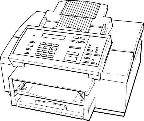
HP OfficeJet Printer/Fax/Copier 1-2. . . . . . . . . . . . . . . . . . . . . . . . . . . . . . . . . . . . . . . . . . . . . . . . . . . . . . . . . . . .
Maximum Media Print Area 1-12. . . . . . . . . . . . . . . . . . . . . . . . . . . . . . . . . . . . . . . . . . . . . . . . . . . . . . . . . . . . . . .
Tray Assemblies 1-14. . . . . . . . . . . . . . . . . . . . . . . . . . . . . . . . . . . . . . . . . . . . . . . . . . . . . . . . . . . . . . . . . . . . . . . . .
Removing the Protective Cover from the Back of the Control Panel Assembly 2-10. . . . . . . . . . . . . . . . . . . . . . . .
Installing the Print Cartridge 2-11. . . . . . . . . . . . . . . . . . . . . . . . . . . . . . . . . . . . . . . . . . . . . . . . . . . . . . . . . . . . . . .
Installing an Interface Cable for Printing 2-12. . . . . . . . . . . . . . . . . . . . . . . . . . . . . . . . . . . . . . . . . . . . . . . . . . . . .
Installing the Power Cord 2-13. . . . . . . . . . . . . . . . . . . . . . . . . . . . . . . . . . . . . . . . . . . . . . . . . . . . . . . . . . . . . . . . .
Installing a Document Catch Tray (optional) 2-13. . . . . . . . . . . . . . . . . . . . . . . . . . . . . . . . . . . . . . . . . . . . . . . . . .
Installing an Access Door Assembly 2-15. . . . . . . . . . . . . . . . . . . . . . . . . . . . . . . . . . . . . . . . . . . . . . . . . . . . . . . . .
Installing an Output Tray 2-15. . . . . . . . . . . . . . . . . . . . . . . . . . . . . . . . . . . . . . . . . . . . . . . . . . . . . . . . . . . . . . . . . .
Installing an Input Tray 2-16. . . . . . . . . . . . . . . . . . . . . . . . . . . . . . . . . . . . . . . . . . . . . . . . . . . . . . . . . . . . . . . . . . .
Installing a Tray Cover 2-17. . . . . . . . . . . . . . . . . . . . . . . . . . . . . . . . . . . . . . . . . . . . . . . . . . . . . . . . . . . . . . . . . . .
Loading Paper in the Input (Paper) Tray 2-18. . . . . . . . . . . . . . . . . . . . . . . . . . . . . . . . . . . . . . . . . . . . . . . . . . . . . .
Loading Envelopes in the Input (Paper) Tray 2-19. . . . . . . . . . . . . . . . . . . . . . . . . . . . . . . . . . . . . . . . . . . . . . . . . .
Connecting the HP OfficeJet to the Telephone Wall Jack (U.S., Australia, Canada, Mexico Installations) 2-22. . .
Connecting a Telephone to the HP OfficeJet (U.S., Australia, Canada, Mexico Installations) 2-23. . . . . . . . . . . . .
Connecting an Answering Machine to the HP OfficeJet (U.S., Australia, Canada, Mexico Installations) 2-24. . . .
Connecting the HP OfficeJet to the Telephone Wall Jack (U.K. Installation) 2-32. . . . . . . . . . . . . . . . . . . . . . . . . .
Connecting a Telephone for use with the HP OfficeJet (U.K. Installation) 2-33. . . . . . . . . . . . . . . . . . . . . . . . . . .
Connecting an Answering Machine for use with the HP OfficeJet (U.K. Installation) 2-33. . . . . . . . . . . . . . . . . . .
Connecting the HP OfficeJet to the Telephone Wall Jack (Germany Installation) 2-34. . . . . . . . . . . . . . . . . . . . . .
Connecting a Telephone or Answering Machine for use with the HP OfficeJet (Germany Installation) 2-34. . . . .
Connecting the HP OfficeJet to the Telephone Wall Jack (France Installation) 2-35. . . . . . . . . . . . . . . . . . . . . . . .
Connecting a Telephone for use with the HP OfficeJet (France Installation) 2-36. . . . . . . . . . . . . . . . . . . . . . . . . .
Connecting an Answering Machine for use with the HP OfficeJet (France Installation) 2-37. . . . . . . . . . . . . . . . .
Connecting the HP OfficeJet to the Telephone Wall Jack (Netherlands Installation) 2-38. . . . . . . . . . . . . . . . . . . .
Connecting a Telephone for use with the HP OfficeJet (Netherlands Installation) 2-39. . . . . . . . . . . . . . . . . . . . . .
Connecting an Answering Machine for use with the HP OfficeJet (Netherlands Installation) 2-40. . . . . . . . . . . . .
Changing a Print cartridge 3-2. . . . . . . . . . . . . . . . . . . . . . . . . . . . . . . . . . . . . . . . . . . . . . . . . . . . . . . . . . . . . . . . .
Calibration Chart 4-4. . . . . . . . . . . . . . . . . . . . . . . . . . . . . . . . . . . . . . . . . . . . . . . . . . . . . . . . . . . . . . . . . . . . . . . .
Diagnostic Code (Sample Report Form) 5-22. . . . . . . . . . . . . . . . . . . . . . . . . . . . . . . . . . . . . . . . . . . . . . . . . . . . .
HP OfficeJet Fax Session Protocol Diagram 5-24. . . . . . . . . . . . . . . . . . . . . . . . . . . . . . . . . . . . . . . . . . . . . . . . . .
Service and Factory Menu 5-36. . . . . . . . . . . . . . . . . . . . . . . . . . . . . . . . . . . . . . . . . . . . . . . . . . . . . . . . . . . . . . . .
xi
Tables
HP OfficeJet (LX) Features 1-3. . . . . . . . . . . . . . . . . . . . . . . . . . . . . . . . . . . . . . . . . . . . . . . . . . . . . . . . . . . . . . .
Simultaneous Tasking Matrix 1-4. . . . . . . . . . . . . . . . . . . . . . . . . . . . . . . . . . . . . . . . . . . . . . . . . . . . . . . . . . . . . .
HP OfficeJet Specifications 1-7. . . . . . . . . . . . . . . . . . . . . . . . . . . . . . . . . . . . . . . . . . . . . . . . . . . . . . . . . . . . . . . .
Ordering Information 1-13. . . . . . . . . . . . . . . . . . . . . . . . . . . . . . . . . . . . . . . . . . . . . . . . . . . . . . . . . . . . . . . . . . . . .
Error Notification: Beeps, Blinking Lights and Messages 5-6. . . . . . . . . . . . . . . . . . . . . . . . . . . . . . . . . . . . . . . .
Display Messages: What They Mean and What to do 5-7. . . . . . . . . . . . . . . . . . . . . . . . . . . . . . . . . . . . . . . . . . .
Solving Problems While Printing, Faxing or Copying 5-16. . . . . . . . . . . . . . . . . . . . . . . . . . . . . . . . . . . . . . . . . . .
Diagnostic Codes: What They Are, How to Read Them and What to do 5-22. . . . . . . . . . . . . . . . . . . . . . . . . . . .
Diagnostic Codes 5-25. . . . . . . . . . . . . . . . . . . . . . . . . . . . . . . . . . . . . . . . . . . . . . . . . . . . . . . . . . . . . . . . . . . . . . .
T30 States – Receive Errors 5-27. . . . . . . . . . . . . . . . . . . . . . . . . . . . . . . . . . . . . . . . . . . . . . . . . . . . . . . . . . . . . . . .
T30 States – Transmit Errors 5-28. . . . . . . . . . . . . . . . . . . . . . . . . . . . . . . . . . . . . . . . . . . . . . . . . . . . . . . . . . . . . .
Communication Error Codes (Level 400) 5-29. . . . . . . . . . . . . . . . . . . . . . . . . . . . . . . . . . . . . . . . . . . . . . . . . . . . .
Communication Error Codes (Level 500) 5-31. . . . . . . . . . . . . . . . . . . . . . . . . . . . . . . . . . . . . . . . . . . . . . . . . . . . .
Power-On Initialization Sequence Tests 5-34. . . . . . . . . . . . . . . . . . . . . . . . . . . . . . . . . . . . . . . . . . . . . . . . . . . . . .
Special Menus and Functions 5-35. . . . . . . . . . . . . . . . . . . . . . . . . . . . . . . . . . . . . . . . . . . . . . . . . . . . . . . . . . . . . .
System Error Codes 5-41. . . . . . . . . . . . . . . . . . . . . . . . . . . . . . . . . . . . . . . . . . . . . . . . . . . . . . . . . . . . . . . . . . . . .
HP OfficeJet User Menu – Associated Parameter Structure 5-42. . . . . . . . . . . . . . . . . . . . . . . . . . . . . . . . . . . . . . .
HP OfficeJet Parameter Descriptions 5-43. . . . . . . . . . . . . . . . . . . . . . . . . . . . . . . . . . . . . . . . . . . . . . . . . . . . . . . .
Exchange Unit Ordering Information 6-3. . . . . . . . . . . . . . . . . . . . . . . . . . . . . . . . . . . . . . . . . . . . . . . . . . . . . . . .
Resources for U.S. Customers 6-4. . . . . . . . . . . . . . . . . . . . . . . . . . . . . . . . . . . . . . . . . . . . . . . . . . . . . . . . . . . . .
Resources for Resellers 6-6. . . . . . . . . . . . . . . . . . . . . . . . . . . . . . . . . . . . . . . . . . . . . . . . . . . . . . . . . . . . . . . . . . .
Resources for HP Authorized Dealers 6-7. . . . . . . . . . . . . . . . . . . . . . . . . . . . . . . . . . . . . . . . . . . . . . . . . . . . . . . .
Resources for Canadian Product Support 6-8. . . . . . . . . . . . . . . . . . . . . . . . . . . . . . . . . . . . . . . . . . . . . . . . . . . . .
Resources for European Product Support 6-9. . . . . . . . . . . . . . . . . . . . . . . . . . . . . . . . . . . . . . . . . . . . . . . . . . . . .
Resources for Australian Product Support 6-12. . . . . . . . . . . . . . . . . . . . . . . . . . . . . . . . . . . . . . . . . . . . . . . . . . . .
HP Regional Sales Offices 6-13. . . . . . . . . . . . . . . . . . . . . . . . . . . . . . . . . . . . . . . . . . . . . . . . . . . . . . . . . . . . . . . .
xii
Notes

Product Information 1-1
1
Product Information
Subject Page
Introduction 1-2. . . . . . . . . . . . . . . . . . . . . . . . . . . . . . . . . . . . . . . . . . . . . . . . . . . . . . . . . . . . . . . . . . . . . . . . . . . .
Product Description 1-2. . . . . . . . . . . . . . . . . . . . . . . . . . . . . . . . . . . . . . . . . . . . . . . . . . . . . . . . . . . . . . . . . . . . . .
Product Features 1-3. . . . . . . . . . . . . . . . . . . . . . . . . . . . . . . . . . . . . . . . . . . . . . . . . . . . . . . . . . . . . . . . . . . . . . . .
Simultaneous Tasking Features 1-4. . . . . . . . . . . . . . . . . . . . . . . . . . . . . . . . . . . . . . . . . . . . . . . . . . . . . . . . . . . . .
Product Specifications 1-7. . . . . . . . . . . . . . . . . . . . . . . . . . . . . . . . . . . . . . . . . . . . . . . . . . . . . . . . . . . . . . . . . . . .
Print Cartridges 1-10. . . . . . . . . . . . . . . . . . . . . . . . . . . . . . . . . . . . . . . . . . . . . . . . . . . . . . . . . . . . . . . . . . . . . . . . .
Software Programs 1-10. . . . . . . . . . . . . . . . . . . . . . . . . . . . . . . . . . . . . . . . . . . . . . . . . . . . . . . . . . . . . . . . . . . . . . .
Media 1-10. . . . . . . . . . . . . . . . . . . . . . . . . . . . . . . . . . . . . . . . . . . . . . . . . . . . . . . . . . . . . . . . . . . . . . . . . . . . . . . . .
Media Tray Capacities 1-11. . . . . . . . . . . . . . . . . . . . . . . . . . . . . . . . . . . . . . . . . . . . . . . . . . . . . . . . . . . . . . . . . . . .
Media Print Area 1-12. . . . . . . . . . . . . . . . . . . . . . . . . . . . . . . . . . . . . . . . . . . . . . . . . . . . . . . . . . . . . . . . . . . . . . . .
Ordering Information 1-13. . . . . . . . . . . . . . . . . . . . . . . . . . . . . . . . . . . . . . . . . . . . . . . . . . . . . . . . . . . . . . . . . . . . .
Product Information1-2
Introduction
This Technical Support Solutions Guide contains information necessary to support the HP OfficeJet
Printer/Fax/Copier family of products. Although model and country-specific functionality may differ across the HP
OfficeJet product line, the support and service strategy is consistent. The products covered in this guide will be
commonly referred to as the HP OfficeJet except where model or country-specific differences are noted. This guide is
divided into six chapters as follows:
DChapter 1 Product Information
DChapter 2 Installation and Configuration
DChapter 3 Routine Maintenance
DChapter 4 Calibration and Adjustment
DChapter 5 Problem Resolution
DChapter 6 Service and Support Information
This Technical Support Solutions Guide is designed to be used with the HP OfficeJet LX User’s Guide as a complete
technical support reference package. This guide and the HP OfficeJet LX User’s Guide also support the standard HP
OfficeJet. The LX version is the HP OfficeJet with added PC-FAX functionality. Typical user setup tasks are
contained in the User’s Guide and answers to questions related to such tasks can be found there. Refer to the User’s
Guide when questions about setup, user settings and printer/fax/copier use are encountered. Refer to this guide for
information on troubleshooting and service and support programs.
Product Description
The HP OfficeJet is a plain paper, thermal inkjet printer/facsimile (fax)/convenience copier machine. It is CCITT
group 3-ECM compatible. Designed to fit on a desktop, the HP OfficeJet weighs 8.8.5 kg (19.5 lb). The HP OfficeJet
has a full-featured printer, which can be used with your PC and either Windows or DOS drivers, and has 16 kB of
printer memory. Its built–in fax machine feature provides many advanced fax features including speed dialing
capability for 65 stations, with a 10 seconds per page transmission speed and 24 page fax memory. As a convenience
copier, the HP OfficeJet can be set to copy up to 99 copies of an original at a speed of 50 seconds per page. The LX
version of the HP OfficeJet uses Eclipse FAXR SE which provides the ability to send faxes directly from the Personal
Computer (PC), receive faxes to the PC, and scan images into PC-based files. The LX version also uses a management
function that allows the HP OfficeJet LX to be set up from the PC using Windows-based menus. The HP OfficeJet
uses cut–sheet plain paper (100 sheet paper tray capacity) and a thermal inkjet cartridge.
HP OfficeJet (LX) Printer/Fax/Copier

Product Information 1-3
Product Features
The following table lists the features of the HP OfficeJet (LX) described in this guide.
HP OfficeJet (LX) Features
Feature Description
Shares a single line with the telephone and a
telephone answering machine (TAM) Answering machine answers all calls. While your
greeting plays, the OfficeJet listens for a fax tone. If
fax tone is detected, the OfficeJet takes the call.
Speed dialing A two-digit number represents a telephone number.
Provides quick and easy dialing for up to 60 loca-
tions and 5 groups of numbers.
Fax settings Settings allow the user or service person to
customize the fax for specific needs.
Halftone scanning The ability to interpret shades of gray into dot
patterns to produce an appearance of gray in an
image. Improves the image quality of photographs.
Error Correction Mode Detects errors that occur during the transmission of a
document and automatically requests resending of
the erroneous portion.
Automatic Journals The HP OfficeJet can be set to print a summary sheet
of each transaction or polling operation, to print a
journal of the last 30 transactions, print a record of
the speed dial numbers stored in memory, print a
menu structure diagram with current settings and to
print self-test and demo reports.
Print from PC functionality Allows printing of print jobs from the personal
computer, when using appropriate printer driver.
Copy functionality Allows for up to 99 copies of an original, includes
copy reduction.
Polling and being polled Ability to have a document ready for retrieval by
another fax station and to call other fax stations to
retrieve information.
Sending faxes at deferred times The ability to delay fax transmissions to another
station until a user-set time is reached.
Automatic and fixed print reduction modes Print reduction modes which fit an incoming
document onto a given paper size.
Automatic and manual redialing Automatically redials if the line is busy or no
answer; retains the last number dialed. Redials up to
5 times at 5 minute intervals.
Backup (Out-of-paper, out-of-ink) reception Stores incoming faxes and print jobs in memory if
out of paper or ink, or paper or ink is not installed.
Remote diagnostics Allows remote access to all user settings and ma-
chine parameters.
(Continued on next page)
Product Information1-4
HP OfficeJet Features (Continued)
Feature Description
Sending to multiple fax numbers The ability to send a document to multiple (up to 10)
fax numbers.
Memory reception capacity Depending upon amount of information on pages
sent, memory allows for up to 24 page storage.
Fax to/from PC functionality
(HP OfficeJet LX only, using the Eclipse FAX SE
software program provided)
The ability to send and receive faxes from the PC
using Eclipse FAX SE functionality. Faxes can be
sent directly from the PC without printing them and
faxes can be received either to paper or to the PC
where they can be viewed, filed or printed.
HP OfficeJet LX Manager
(HP OfficeJet LX only, using the HP OfficeJet LX
Manager software program provided)
Allows the user to setup and monitor the status of the
HP OfficeJet LX from the PC using Windows-based
menus.
Convenience Scanning The user can use the HP OfficeJet LX as a conve-
nience scanner to scan images into PC-based files.
Software Programs Windows and DOS printer drivers, a scanner driver
and printer fonts are provided.
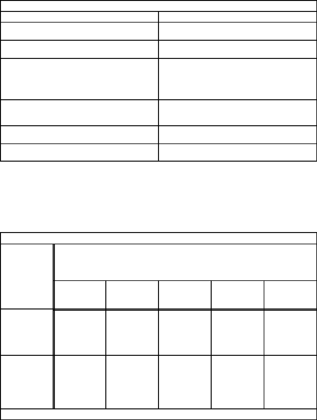
Simultaneous Tasking Features
The HP OfficeJet (LX) is capable of performing several tasks at the same time. Use the following chart as a reference
of which tasks can be performed simultaneously. Attempting to perform concurrent tasks not supported may result in
a display message or error condition.
Simultaneous Tasking Matrix
If the HP
OfficeJet (LX)
is:
Note: PC fax capability is only present in the LX version
Can I?
Send a print
job or print a
PC fax
Receive a
paper fax Receive a PC
fax (LX only) Send a fax
from the ADF Send a PC fax
(LX only)
Printing a PC
file or printing
a PC fax
YES
automatically
prints when
the first PC job
ends
YES
automatically
prints when PC
print job ends
YES YES YES
Receiving a
paper fax YES
automatically
prints when
fax printing
ends
YES
automatically
prints when the
first fax is
finished
printing
YES YES YES
(Continued on next page)

Product Information 1-5
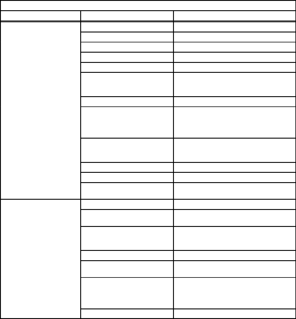
Simultaneous Tasking Matrix (Continued)
If the HP
OfficeJet (LX)
is:
Note: PC fax capability is only present in the LX version
Can I?
Send a print
job or print a
PC fax
Receive a
paper fax Receive a PC
fax (LX only) Send a fax
from the ADF Send a PC fax
(LX only)
Receiving a PC
fax (LX only) YES
(with delay)
print manager
automatically
sends print job
as soon as
received fax is
complete
NO
two faxes
cannot be
transmitted
over the same
phone line at
the same time
NO
two faxes
cannot be
transmitted
over the same
phone line at
the same time
NO
two faxes
cannot be
transmitted
over the same
phone line at
the same time
YES
(with delay)
print manager
will send PC
fax as soon as
fax is complete
Sending a fax
from the ADF YES NO
two faxes
cannot be
transmitted
over the same
phone line at
the same time
NO
two faxes
cannot be
transmitted
over the same
phone line at
the same time
NO
two faxes
cannot be
transmitted
over the same
phone line at
the same time
YES
(with delay)
print manager
will send PC
fax as soon as
fax is complete
Sending a PC
fax (LX only) YES
(with delay)
print manager
sends one job
as soon as one
is complete
NO
two faxes
cannot be
transmitted
over the same
phone line at
the same time
NO
two faxes
cannot be
transmitted
over the same
phone line at
the same time
NO
two faxes
cannot be
transmitted
over the same
phone line at
the same time
YES
(with delay)
print manager
sends one fax
as soon as first
is complete
Making a Copy YES
automatically
prints when
copying ends
YES
automatically
prints when
copying ends
YES NO
two documents
cannot be
scanned from
the ADF at the
same time
YES
Scanning NO
scanning ties
up PC
resources
YES NO
PC fax will be
routed to paper
fax
NO
two documents
cannot be
scanned from
the ADF at the
same time
NO
scanning ties
up PC
resources
Product Information1-6
The following task combinations can be performed simultaneously.
1. An incoming fax will be stored in memory while:
Dfaxes in memory are printing
Da local copy is printing
Da print job is printing
Da report is printing
2. A fax can be sent from the automatic document feeder while:
Dfaxes in memory are printing
Da print job is printing
Da report is printing
3. Print jobs can be printed while:
Da fax is being sent from the automatic document feeder
Da delayed send fax from memory is being sent
Da delayed send fax from the automatic document feeder is being sent
Da broadcast fax from memory is being sent
Da document is polled from the automatic document feeder
4. A delayed send fax from memory can be sent while:
Da print job is printing
5. A broadcast fax from memory can be sent while:
Da print job is printing
6. A delayed send fax from the automatic document feeder can be sent while:
Da print job is printing
7. Remote fax machines can poll the HP OfficeJet while:
Dfaxes in memory are printing
Da print job is printing
Da report is printing
8. Faxes in memory can be printed while:
Dan incoming fax is stored in memory (and takes over the display)

Product Information 1-7
Product Specifications
Review the following table for product specifications of the HP OfficeJet.
HP OfficeJet Specifications
Function Specification Description
Overall Specifications Dimensions 17.25 w x 15.5 d x 11.125 h (inches)
438 w x 394 d x 283 h (mm)
Weight 19.5 lb (8.85 kg)
Power Source (autoranging) 100-240 Vac, 1.0 A, 50-60 Hz
Power Consumption 10 watts at idle, 45 watts maximum
Operating Environment Temperature range for best print quality:
15°C (59°F) to 35°C (95°F)
Allowable temperature/humidity range:
5°C (41°F) to 40°C (104°F), 15-80% RH
non-condensing
Maximum noise level generated:
Sound Power, LwAd = 6.4 B(A)
Sound Pressure, LpAm = 50 dB(A)
Printer Specifications Print Method Plain paper drop-on-demand thermal inkjet
Printer Memory 16 kB
Printer Command Language HP PCL Level 3
Printer Interface Parallel (Centronics)
Resolution
(dots per inch = dpi)
Windows:
Presentation mode = 600 x 300 dpi with
REt
Normal mode = 600 x 300 dpi with REt
Fast mode = 300 dpi
DOS (text):
Letter quality = 600 x 300 dpi with REt
Draft quality = 300 dpi with ink reduction
Print Speed
(page(s) per minute = ppm)
(characters per second = cps)
(characters per inch = cpi)
Windows print speed:
Presentation mode = 1 ppm
Normal mode = 2.5 ppm
Fast mode = 3 ppm
DOS print speed:
Letter quality = 167 cps at 10 cpi
Draft quality = 240 cps at 10 cpi
Paper sizes U.S. letter = 8.5 x 11 in.
U.S. legal = 8.5 x 14 in.
European A4 = 210 x 297 mm
Executive = 7.25 x 10.5 in
U.S. No. 10 envelope = 4.12 x 9.5 in
European DL envelope = 220 x 110 mm
U.S. transparency = 8.5 x 11 in.
European A4 transparency = 210x297 mm

Product Information1-8
HP OfficeJet Specifications (continued)
Function Specification Description
Printer Specifications
(continued)
Internal Fonts Courier (Portrait Orientation):
Pitch: 5, 10, 16.67, 20 cpi
Point size: 6, 12 pt.
CG Times (Portrait Orientation):
Pitch: Proportional
Point size: 5, 6, 7, 8, 10, 12, 14 pt.
Letter Gothic (Portrait Orientation):
Pitch: 6, 12, 24 cpi
Point size: 6, 12 pt.
Univers (Portrait Orientation):
Pitch: Proportional
Point size: 5, 6, 7, 8, 10, 12, 14 pt.
Courier (Landscape Orientation):
Pitch: 10, 16.67, 20 cpi
Point size: 6, 12, 24 pt.
Letter Gothic (Landscape Orientation)
Point and Pitch: 6, 12, 24 pt for 12, 24 cpi;
4.75, 9.5, 19 pt for 16.67 cpi
Character Set Support PC-8, HP Roman 8, PC-8
Danish/Nor, UK ISO 4, German ISO 21,
French ISO 69, Italian ISO 15, Nor v.1 ISO
60, Swed Names ISO 11, Spanish ISO 17,
ASCII, Portug ISO 16, PC-850, ECMA-94
Latin 1, HP Legal
Printing Margins
(These numbers represent the
maximum printable area for this
device. However, your printer
driver may create a smaller
printable area.)
U.S. letter-size paper:
Top margin = 1.0 mm 〈± 1.0 mm)
Bottom margin = 10.9 mm (±0.6 mm)
Left margin = 6.4 mm (±1.0 mm)
Right margin = 6.4 mm (±1.0 mm)
European A4-size paper:
Top margin = 1.0 mm 〈± 1.0 mm)
Bottom margin = 10.9 mm (±0.6 mm)
Left margin = 3.4 mm (±1.0 mm)
Right margin = 3.4 mm (±1.0 mm)
Vertical Alignment ±0.002 in.
Scalable TrueTypet Fonts
for MicrosoftE Windows
Arial Black, CG Goudy Old Style,
Phyllis, Graphite Light, CG Poster
Bodoni, LucidaCasual, Gill Sans
Shadow, Milestone Font, Signet
Roundhand, and PL Benguiat Frisky
Software Compatibility Microsoft Windows 3.1
WordPerfect
Lotus 1-2-3 for DOS
Also compatible with a range of DOS
applications (HP DeskJet), OS/2 versions
1.3, 2.0, 2.1 (HP DeskJet), and Microsoft
Windows 3.0 (HP DeskJet)
Product Information 1-9
HP OfficeJet Specifications (continued)
Function Specification Description
Fax Specifications Coding Schemes MH, MR, MMR
Compatibility CCITT Group 3
Distinctive Ring Detect Yes
Image Memory 24 pages (CCITT chart #1, about 400 kB)
Modem Speed 9600, 7200, 4800 and 2400 bits per second
Paper Sizes U.S. letter = 8.5 x 11 in.
U.S. legal = 8.5 x 14 in.
European A4 = 210 x 297 mm
Paper Weight (faxes sent) 16 to 24 lb (60 to 90 g/m2)
Scan Margins (faxes sent) Top margin = 3.0 mm ± 3.0 mm
Bottom margin = 0.0 mm ± 4.0 mm
Center line = 0.0 mm ± 2.5 mm
Width = 216.2 mm ± 2.6 mm
Scan Resolution Standard = 100 x 200 dpi
Fine = 200 x 200 dpi
Photo = 200 x 200 dpi, 32 level grayscale
Scan Width Maximum = 8.5 inches (216 mm)
Speed Dialing 65 locations, including 5 groups
Transmission Speed 10 seconds per page
(CCITT chart #1 using ECM)
Copier Specifications Copy Speed 50 seconds per page
Scan Resolution Fine = 200 x 200 dpi
Photo = 200 x 200 dpi, 32 level grayscale
Paper Sizes U.S. letter = 8.5 x 11 in.
U.S. legal = 8.5 x 14 in.
European A4 = 210 x 297 mm
Multiple Copies Up to 99 (per full paper tray)
Copy Reduction 100%, 95%, 90%, 85%, 80%,
75% (Legal-to-Letter), 70%
Scan Margins Top margin = 3.0 mm ± 3.0 mm
Bottom margin = 2.0 mm ± 3.0 mm
Center line = 0.0 mm ± 2.5 mm
Width = 216.2 mm ± 2.6 mm
Scan Width Maximum = 8.5 inches (216 mm)
Product Information1-10
Print Cartridges
The HP OfficeJet uses one high–capacity black print cartridge, HP part number 51626A.
When printing text only on letter-size media, ink lasts, on average, about 1000 pages. Text used was CCITT test image
number 1, the Slerexe Company letter. If text of greater density is printed or quality mode is used, results may vary
considerably. Ink cartridge longevity is also affected by larger paper sizes containing more printed matter or photos or
illustrations. If the ink lasts much less than 1000 pages, ensure that you have removed both pieces of tape from the
print cartridge before beginning to use it, and that the conductive part of the cartridge surface is clean.
Software Programs
Several software programs and drivers are provided. The Eclipse FAX SE and HP OfficeJet LX Manager programs are
only provided and used with the LX version. The Windows and DOS drivers are provided with all models.
DEclipse FAX SE allows the user to send high-quality faxes directly from the PC, receive faxes to the PC,
and scan images into PC-based files.
DHP OfficeJet LX Manager lets the user setup the HP OfficeJet LX from the PC, using Windows-based
menus, rather than the device’s front panel. The Manager also serves as a status monitor, displaying
information and error messages and also tells the user whether or not the HP OfficeJet LX is properly
connected.
DWindows and DOS printer drivers, printer fonts and a scanner driver are provided.
Media
An HP OfficeJet works with ordinary bond and photocopy papers. Paper properties are subject to change by paper
manufacturers, and Hewlett-Packard has no control over such changes. For optimum print quality, test paper (printing
on both sides) for suitability, before you purchase large quantities.
Use plain bond or white photocopy paper of high quality. It should be free of:
DCarbon
DCuts or tears
DGrease spots
DLoose particles
DDust
DWrinkles
DCurled, bent or frayed edges
Colored bond and photocopy paper (such as pink, yellow, or blue) can be used, as long as it meets these specifications:
DPaper Size U.S. letter (8 1/2 in x 11 in), (216 x 279 mm)
U.S. legal (8 1/2 in x 14 in), (215 x 356 mm)
Executive (7.25 x 10.5 in), (184 mm x 267 mm)
A4 metric (8.27 x 11.7 in), (210 mm x 297 mm)
DEnvelope Size U.S. No. 10 (4.12 x 9.5 in), (105 x 241 mm)
European DL (8.66 x 4.33 in), (220 x 110 mm)
DPaper Type Cut sheet
Product Information 1-11
DCut Edge Conditions Sharp blade cut, with no visible fray.
DFinishing Dimensions ± 0.0313 inch of nominal, corners 90_± 0.20_
DPaper Grain Long grain
DMoisture Content 4% to 6% by weight
DOpacity 84% minimum
DPackaging Polylaminated moisture-proof ream wrap
DPaper weight 60 to 135 g/m2 (16 lb to 36 lb), 75 g/m2 (20 lb) recommended
DWax Pick 2 inch minimum (Dennison)
Paper can be loaded automatically or manually. When loading paper, observe the following precautions:
DHandle all paper by the edges only
DLoad all paper types the same way
DUse only one paper type in the printer’s paper tray at a time
DAlways load paper print side up in the media tray
Plain paper has a print side which is not visible to the naked eye, so before removing paper from its package for use in
the printer, check the outside package label. Always load the paper into the machine with the print side facing down.
The print side will be indicated by an arrow or other symbol on the label.
Avoid the following types of media:
DPaper greater than 135 g/m2 (36 lb) or less than 60 g/m2 (16 lb)
DPaper with cutouts or perforations
DMultiple part forms
DCarbon copy forms
DPaper sizes other than those listed in this document
Media Tray Capacities
Sheet capacity for the various paper tray is as follows:
DAccess door assembly (automatic document feed tray for faxes to be sent)
= 20 pages (paper weight ≤ 20 lb or 75 g/m2)
Minimum paper width = 6 in. (152 mm)
Maximum paper width = 8.5 in. (216 mm)
Maximum paper length = 17 in. (432 mm)
DInput Tray = 100 sheets at a paper weight ≤ 20 lb (75 g/m2) or 20 envelopes (U.S. No. 10 or European DL)
DOutput tray = 100 sheets at a paper weight ≤ 20 lb (75 g/m2)
Product Information1-12
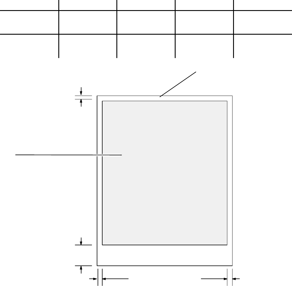
Media Print Area
Maximum printable area for the HP OfficeJet is dependent upon the media size being used. The printable area for the
media sizes are shown in the following diagram.
Paper Size Left Margin Right Margin Top Margin Bottom Margin
U.S. Letter
8.5 x 11 in.
(215 x 279 mm)
6.4 mm ± 1.0 mm
(0.25 x 0.04 in.) 6.4 mm ± 1.0 mm
(0.25 x 0.04 in.) 1.0 mm ± 1.0 mm
(0.04 x 0.04 in.) 10.9 mm ± 0.06 mm
(0.42 x 0.02 in.)
European A4
210 x 297 mm
(8.27 x 11.7 in.)
3.4 mm ± 1.0 mm
(0.13 x 0.04 in.) 3.4 mm ± 1.0 mm
(0.13 x 0.04 in.) 1.0 mm ± 1.0 mm
(0.04 x 0.04 in.) 10.9 mm ± 0.06 mm
(0.42 x 0.02 in.)
Printable area
Letter: 8.0 by 10.5 in
(203 by 267 mm)
Legal: 8.0 by 13.5 in
(203 by 343 mm)
A4 7.8 by 11.2 in
(198 by 284 mm
1.0 mm
(0.04 in)
10.9 mm
(0.42 in)
6.4 mm (0.25 in.)
Maximum Media Print Area
6.4 mm (0.25 in.)
U.S. Letter 8.5 x 11 in. (215 x 279 mm)
European A4 210 x 297 mm (8.27 x 11.7 in.)
Paper Size:
U.S. Legal 11 x 14 in. (279 x 356 mm)

Product Information 1-13
Ordering Information
Information on ordering exchange units under the HP Exchange program is provided with the program information in
Chapter 6 of this manual.
To order the supplies and accessories listed in the table below, contact your HP dealer. If your dealer is out of stock,
you can order directly from HP for fast shipping service:
Within the U.S.: Call 1-800-538-8787 for all supplies/accessories except documents.
Call 1-800-227-8164 to order user’s guides and technical reference guides.
In Canada: In Toronto, call 905-206-4727.
In the rest of Canada, call 1-800-387-3154.
In Europe: Refer to the European Product Support table in Chapter 6. The various countries have
different organizations to contact for support.
Availability, technical information and items shipped with the HP OfficeJet are subject to change without notice.
Ordering Information
Supply/Accessory HP Reorder Part Number
Centronics Parallel Interface Cable (shielded) HP C950A (2 meter), or HP C2951A (3 meter)
High Capacity InkJet Print Cartridge 51626A
Media
LX JetSeries Transparency Film (U.S. Letter)
LX JetSeries Transparency Film (European A4)
LX JetSeries Glossy Paper (U.S. Letter)
LX JetSeries Glossy Paper (European A4)
51636F
51636G
51636H
51636J
HP OfficeJet and HP OfficeJet LX User’s Guides
North America (English)
Canadian French
European French
German
Netherlands (Dutch)
United Kingdom (English)
Spanish (Mexico)
Australia (English)
HP OfficeJet HP OfficeJet LX
C2890-90001 C2891-90001
C2890-90003 C2891-90003
C2891-90004
C2891-90005
C2891-90011
C2891-90000
C2891-90006
C2891-90007
HP DeskJet 500 Series Technical Reference Guide C2170-90099
Access Door (see diagram on next page) C2890-60064
Tray Cover (see diagram on next page) C2890-40054
Output Tray Assembly (see diagram on next page) C2890-60006
Document Catch Tray (see diagram on next page) C2890-60160
Input Tray Assembly (see diagram on next page) C2890-60005
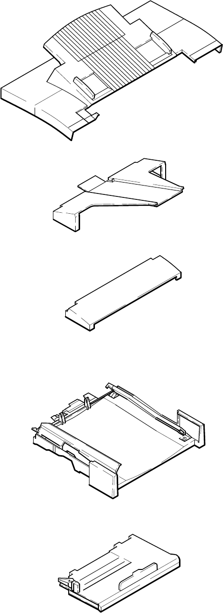
Product Information1-14
Access Door Assembly
Tray Cover
Output Tray Assembly
Document Catch Tray Assembly
Input Tray Assembly
Tray Assemblies

2-1
Installation and Configuration
2
Installation and Configuration
Subject Page
Introduction 2-2. . . . . . . . . . . . . . . . . . . . . . . . . . . . . . . . . . . . . . . . . . . . . . . . . . . . . . . . . . . . . . . . . . . . . . . . . . . .
Using Printer Driver Software 2-2. . . . . . . . . . . . . . . . . . . . . . . . . . . . . . . . . . . . . . . . . . . . . . . . . . . . . . . . . . . . . .
Using Microsoft Windows 3.1 2-2. . . . . . . . . . . . . . . . . . . . . . . . . . . . . . . . . . . . . . . . . . . . . . . . . . . . . . . . . . .
Using OS/2 2-3. . . . . . . . . . . . . . . . . . . . . . . . . . . . . . . . . . . . . . . . . . . . . . . . . . . . . . . . . . . . . . . . . . . . . . . . .
Using DOS Software Applications 2-3. . . . . . . . . . . . . . . . . . . . . . . . . . . . . . . . . . . . . . . . . . . . . . . . . . . . . . .
Hardware and Software Requirements 2-3. . . . . . . . . . . . . . . . . . . . . . . . . . . . . . . . . . . . . . . . . . . . . . . . . . . .
Installing the HP OfficeJet LX Software 2-3. . . . . . . . . . . . . . . . . . . . . . . . . . . . . . . . . . . . . . . . . . . . . . . . . . . . . .
Running the HP OfficeJet LX Manager 2-6. . . . . . . . . . . . . . . . . . . . . . . . . . . . . . . . . . . . . . . . . . . . . . . . . . . . . . .
Running the Eclipse FAX SE from the HP OfficeJet LX Manager 2-7. . . . . . . . . . . . . . . . . . . . . . . . . . . . . . . . . .
Sending a Fax Directly from the PC 2-8. . . . . . . . . . . . . . . . . . . . . . . . . . . . . . . . . . . . . . . . . . . . . . . . . . . . . . . . .
Receiving a Fax Directly to the PC 2-9. . . . . . . . . . . . . . . . . . . . . . . . . . . . . . . . . . . . . . . . . . . . . . . . . . . . . . . . . .
Using Other PC Fax Programs With the HP OfficeJet LX 2-10. . . . . . . . . . . . . . . . . . . . . . . . . . . . . . . . . . . . . . . .
Installing a Control Panel Overlay 2-10. . . . . . . . . . . . . . . . . . . . . . . . . . . . . . . . . . . . . . . . . . . . . . . . . . . . . . . . . . .
Installing a Print Cartridge 2-11. . . . . . . . . . . . . . . . . . . . . . . . . . . . . . . . . . . . . . . . . . . . . . . . . . . . . . . . . . . . . . . . .
Installing an Interface Cable for Printing 2-12. . . . . . . . . . . . . . . . . . . . . . . . . . . . . . . . . . . . . . . . . . . . . . . . . . . . .
Installing the Power Cord 2-13. . . . . . . . . . . . . . . . . . . . . . . . . . . . . . . . . . . . . . . . . . . . . . . . . . . . . . . . . . . . . . . . .
Installing a Document Catch Tray (optional) 2-13. . . . . . . . . . . . . . . . . . . . . . . . . . . . . . . . . . . . . . . . . . . . . . . . . .
Installing an Access Door Assembly 2-15. . . . . . . . . . . . . . . . . . . . . . . . . . . . . . . . . . . . . . . . . . . . . . . . . . . . . . . . .
Installing an Output Tray 2-15. . . . . . . . . . . . . . . . . . . . . . . . . . . . . . . . . . . . . . . . . . . . . . . . . . . . . . . . . . . . . . . . . .
Installing an Input Tray 2-16. . . . . . . . . . . . . . . . . . . . . . . . . . . . . . . . . . . . . . . . . . . . . . . . . . . . . . . . . . . . . . . . . . .
Installing a Tray Cover 2-17. . . . . . . . . . . . . . . . . . . . . . . . . . . . . . . . . . . . . . . . . . . . . . . . . . . . . . . . . . . . . . . . . . .
Loading Paper in the Input (Paper) Tray 2-18. . . . . . . . . . . . . . . . . . . . . . . . . . . . . . . . . . . . . . . . . . . . . . . . . . . . . .
Loading Envelopes in the Input (Paper) Tray 2-19. . . . . . . . . . . . . . . . . . . . . . . . . . . . . . . . . . . . . . . . . . . . . . . . . .
Setting the Paper Size in the Menu 2-20. . . . . . . . . . . . . . . . . . . . . . . . . . . . . . . . . . . . . . . . . . . . . . . . . . . . . . . . . .
Setting Up for Printing 2-21. . . . . . . . . . . . . . . . . . . . . . . . . . . . . . . . . . . . . . . . . . . . . . . . . . . . . . . . . . . . . . . . . . . .
Setting Up for Faxing (U.S., Australia, Canada and Mexico Installations) 2-22. . . . . . . . . . . . . . . . . . . . . . . . . . .
Receive fax calls only - no voice calls, on a dedicated fax line 2-22. . . . . . . . . . . . . . . . . . . . . . . . . . . . . . . . .
Receive voice and fax calls at the same phone number - without an answering machine 2-23. . . . . . . . . . . . .
Receive voice and fax calls at the same phone number - with an answering machine 2-24. . . . . . . . . . . . . . . .
Receive fax and voice calls on the same line with distinctive ring 2-25. . . . . . . . . . . . . . . . . . . . . . . . . . . . . . .
Setting the Reception Mode for Incoming Calls 2-27. . . . . . . . . . . . . . . . . . . . . . . . . . . . . . . . . . . . . . . . . . . . . . . .
Setting the Number of Rings to Answer 2-28. . . . . . . . . . . . . . . . . . . . . . . . . . . . . . . . . . . . . . . . . . . . . . . . . . . . . .
Selecting Tone or Pulse Dialing 2-29. . . . . . . . . . . . . . . . . . . . . . . . . . . . . . . . . . . . . . . . . . . . . . . . . . . . . . . . . . . . .
Entering the Date and Time 2-30. . . . . . . . . . . . . . . . . . . . . . . . . . . . . . . . . . . . . . . . . . . . . . . . . . . . . . . . . . . . . . . .
Entering the Header Information (company name and fax number) 2-31. . . . . . . . . . . . . . . . . . . . . . . . . . . . . . . . .
Setting Up for Faxing (U.K. Installation) 2-32. . . . . . . . . . . . . . . . . . . . . . . . . . . . . . . . . . . . . . . . . . . . . . . . . . . . .
Receive fax calls only - no voice calls, on a dedicated fax line 2-32. . . . . . . . . . . . . . . . . . . . . . . . . . . . . . . . .
Receive voice and fax calls at the same phone number - without an answering machine 2-33. . . . . . . . . . . . .
Receive voice and fax calls at the same phone number - with an answering machine 2-33. . . . . . . . . . . . . . . .
Setting Up for Faxing (Germany Installation) 2-34. . . . . . . . . . . . . . . . . . . . . . . . . . . . . . . . . . . . . . . . . . . . . . . . . .
Setting Up for Faxing (France Installation) 2-35. . . . . . . . . . . . . . . . . . . . . . . . . . . . . . . . . . . . . . . . . . . . . . . . . . . .
Receive fax calls only - no voice calls, on a dedicated fax line 2-35. . . . . . . . . . . . . . . . . . . . . . . . . . . . . . . . .
Receive voice and fax calls at the same phone number - without an answering machine 2-36. . . . . . . . . . . . .
Receive voice and fax calls at the same phone number - with an answering machine 2-37. . . . . . . . . . . . . . . .
Setting Up for Faxing (Netherlands Installation) 2-38. . . . . . . . . . . . . . . . . . . . . . . . . . . . . . . . . . . . . . . . . . . . . . .
Receive fax calls only - no voice calls, on a dedicated fax line 2-38. . . . . . . . . . . . . . . . . . . . . . . . . . . . . . . . .
Receive voice and fax calls at the same phone number - without an answering machine 2-39. . . . . . . . . . . . .
Receive voice and fax calls at the same phone number - with an answering machine 2-40. . . . . . . . . . . . . . . .
2-2 Installation and Configuration
Introduction
In this chapter you will find information about installing the software applications provided, including the:
DPrinter Drivers
(including Windows and DOS driver software)
DHP OfficeJet LX Software
(including the HP OfficeJet LX Manager and Eclipse FAX SE (PC fax applications)
You will find information about installing the:
Dcontrol panel overlay (if a new one is being installed)
Dprint cartridge
Dinterface cable for printing
Dpower cord
Ddocument catch tray (installation is optional)
Instructions for installing the following customer orderable and installable parts are also provided:
Daccess door assembly
Doutput tray assembly
Dinput tray assembly
Dtray cover
You will also be provided information on how to:
Dload paper
Dload envelopes
Dset the paper size in the menu
Dset up for printing
Dset up for faxing
Using Printer Driver Software
Detailed information on each of the software installations and their usage is provided in the HP OfficeJet (LX) User’s
Guide. Also, the applications guides provided with each driver will provide specific information for the installation
and use of the software package.
Refer to the options listed below to determine which printer driver you need to install to make your computer and
software work with the HP OfficeJet. Printer drivers (also called printer software) are software files that control your
printer and allow your software application to access the printer’s features.
Using Microsoft) Windows 3.1
Install the HP OfficeJet Printer Software for Microsoft Windows 3.1 provided with your HP OfficeJet. See the
documentation that came with the printer software for installation instructions.
2-3
Installation and Configuration
Using OS/2
The HP OfficeJet is compatible with the HP DeskJet printers. Therefore, look for the HP DeskJet 520 or DeskJet 510
printer model selection in OS/2. If it is not available, contact your IBM representative for information. If the HP
DeskJet 520 or DeskJet 510 printer is listed, install it with the instructions provided by IBM.
Using DOS software applications
For each DOS software application you use, you must install a specific printer driver. Your DOS software application
supplies printer drivers for many printer models. A printer driver that supports your printer features may already be in
your software application. Additional information is provided in this section, see Setting Up for Printing.
Hardware and Software Requirements
The following are the minimum computer system requirements:
DParallel port must support bidirectional communication.
D4 Megabytes (MB) of Random Access Memory (RAM). 8 MB RAM recommended.
D5 MB hard disk space.
DWindows 3.1 operating system.
Note: To add the HP OfficeJet LX Manager to your Windows StartUp group, so that the HP OfficeJet
LX Manager will run automatically whenever you start Windows, make sure that your PC has enough
memory to run the HP OfficeJet LX Manager simultaneously with all the other applications you plan to
run. Then, open the HP OfficeJet LX Manager and StartUp groups, press the Ctrl key, and click and
drag the HP OfficeJet LX Manager icon into the StartUp group.
Installing the HP OfficeJet LX Software
The information provided here will help you with the installation of the HP OfficeJet LX Software including the HP
OfficeJet LX Manager and Eclipse FAX SE software applications. Additionally, other PC Fax programs usable with
the HP OfficeJet LX are described. Detailed information on custom installation and usage is provided in the HP
OfficeJet LX User’s Guide.
Use the following instructions when installing the software for the first time in the HP OfficeJet LX.
1. Check that you have properly set up the HP OfficeJet LX device, and that it is connected to your computer, turned
on, and has paper loaded.
2. Close any open applications, saving files if necessary.
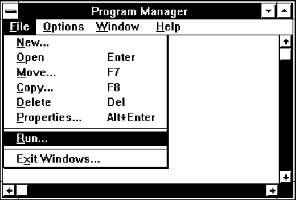
3. Insert Disk 1 of the HP OfficeJet LX software into
your flexible disk drive.
4. From the Windows Program Manager menu bar,
choose File/Run. The Run dialog box appears.

2-4 Installation and Configuration
5. In the Command Line box, type one of the following commands, depending on which flexible disk drive you’re
using:
A:SETUP.EXE
or
B:SETUP.EXE.
6. An “initializing” screen appears, followed by a screen that asks the user to select Standard Installation,
Custom Installation, or Uninstall.
We recommend that first–time users choose Standard Installation, which copies all the HP OfficeJet LX software
to their hard disk and sets up the device for printing, scanning, and PC faxing. For information about Custom
Installation, see “Performing a Custom Installation” in the HP OfficeJet LX User’s Guide. For information about the
uninstall option, see “Using the Uninstall Option” in the HP OfficeJet LX User’s Guide.
Click the Standard Installation button and then the OK button.
7. A screen appears, allowing you to specify the directory in which your HP OfficeJet LX software will be installed.
The default directory is C:\HPOJET.
If this is acceptable, click the OK button.If it is not acceptable, follow the instructions on the screen to select a
different directory. Then click the OK button.
8. As installation takes place, screens are displayed that provide “must know” information about the HP OfficeJet LX.
Reading these screens will give you a head start on understanding how your new product works. Be sure to read these
screens completely before inserting a new installation disk.
9. After all the files have been copied to the hard disk, the setup program tries to communicate with your
HP OfficeJet LX.
If the device is properly connected and turned on, a screen appears, giving you the name of the port to which your HP
OfficeJet LX is connected. Click the OK button.
10. If the setup program cannot find your HP OfficeJet LX, follow the troubleshooting instructions on the screen to
correct the problem. Then click the Retry button. The setup program tries again to communicate with the HP
OfficeJet LX. If it succeeds, a screen appears, giving you the name of the port to which your HP OfficeJet LX is
connected. Click the OK button.
11. The PC Fax Cover Sheet Information dialog box appears. Complete it as directed, pointing and clicking in each
field to fill it in. When you are finished, click the OK button.
12. The Fax Header dialog box appears. Complete it as directed and click the OK button.
13. The Fax Receive Mode dialog box appears. Complete it as directed and click the OK button.
If This Is the User’s Situation ... Choose This Setting
You have a separate telephone number dedicated to receiving fax
calls only (no voice calls). Auto.
You have one telephone number for both voice and fax calls, and
you
don’t
have a telephone answering machine. Manual.
You have one telephone number for both voice and fax calls, and
you
do
have a telephone answering machine. Fax/TAM.
You have one telephone number for both voice and fax calls, and
you subscribe to a
distinctive ringing service
from your telephone
company.
Auto, and click the Distinctive Ring button
in the Settings box.
14. The Dialing Mode dialog box appears. Complete it as directed and click the OK button.
2-5
Installation and Configuration
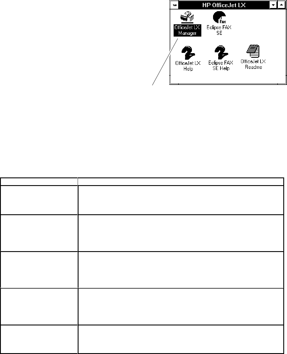
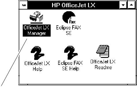
15. Next, the setup program creates the HP OfficeJet LX
program group and places it on the Windows desktop.
It should look similar to this:
16. As a last step, the setup program gives you the option of reading tips that will help you understand the basic
functions of your new product.
As the first “tips” screen appears, your HP OfficeJet LX prints a Self Test report. This report shows samples of your
new internal fonts, reviews the factory device settings, notifies you about any print cartridge problems, and provides
product revision information.
Click the Exit button when you are ready to leave the setup program.
If difficulties arise with the installation, review the following recommendations:
Problem Recommended Action
I am reinstalling the soft-
ware, and the setup program
says I don’t have enough
disk space.
Use the setup program to uninstall the HP OfficeJet LX software. Then try
installing again.
My C: drive is full, so I tried
to install the software on my
D: drive, but the setup pro-
gram still says I don’t have
enough disk space.
The HP OfficeJet LX software requires several files to reside in the drive that
contains your Windows application. If that drive is full, the setup program can-
not install the HP OfficeJet LX software. Free as much space on the drive as
you can by either deleting unneeded files or moving files to a different drive or
onto diskettes. Then try installing again.
The setup program cannot
locate my HP OfficeJet LX. If you have followed the troubleshooting directions on the screen, the most
likely problem is that you need a different centronics cable. (About 10% of
centronics cables cannot support bidirectional communications.)
There is also a chance that your PC’s centronics port is either not set up for or
cannot support bidirectional communications.
I am reinstalling the soft-
ware. It used to run correct-
ly, but now the setup pro-
gram cannot locate the de-
vice.
Make sure that the HP OfficeJet LX Manager is not running. Exit from Win-
dows and then try again. Make sure that (1) the device is properly cabled to
your PC, (2) the device is turned on, and (3) the front panel says “Ready.”
I’m trying to uninstall the
software, but the setup pro-
gram says it cannot delete
the directory.
Either the directory contains files that do not belong to the HP OfficeJet LX, or
one or more files are open. Correct the problem and try again.
The HP OfficeJet LX Manager icon
2-6 Installation and Configuration
Running the HP OfficeJet LX Manager
The HP OfficeJet LX Manager is one of two software applications that are included with the HP OfficeJet LX. The
other software application is Eclipse FAX SE, which lets you do PC faxing and scanning.
The HP OfficeJet LX Manager allows the user to manage the way that their HP OfficeJet LX works. It can be used it to
do the following:
DMonitor the status of the HP OfficeJet LX.
DPrint logs and reports.
DChange the device settings that were made during installation, and make additional settings that control
faxing, printing, and copying.
Note: The HP OfficeJet LX Manager has one other important function: it must be running in order for
you to use Eclipse FAX SE. It can be either open as a window or minimized.
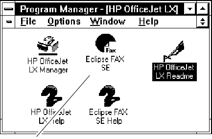
To run the HP OfficeJet LX Manager, double-click the
HP OfficeJet LX Manager icon, which is placed in the
HP OfficeJet LX group during installation. The HP
OfficeJet LX Manager window appears.
You can minimize or close the HP OfficeJet LX Manager
as you would any other Windows application. Remember
that when this application is closed, you can make copies,
print, and send and receive paper faxes, but you cannot
use Eclipse FAX SE to send and receive PC faxes or do
PC scanning.
Additional detailed information on use of the Manager
is provided in the HP OfficeJet LX User’s Guide. The HP OfficeJet LX Manager icon
2-7
Installation and Configuration
Running Eclipse FAX SE from the HP OfficeJet LX Manager
The HP OfficeJet LX includes a software application, Eclipse FAX SE, that allows you to send and receive faxes
directly to your PC, rather than to the device itself, and to do PC scanning.
Note: Eclipse FAX SE is a separate application from the HP OfficeJet LX Manager. Some of the
settings that you can make with the HP OfficeJet LX Manager affect PC faxing. In addition, the HP
OfficeJet LX Manager must be running in order for you to use Eclipse FAX SE. It can be either open
as a window or minimized.
There may be times when you want to run Eclipse FAX SE directly from the HP OfficeJet LX Manager. To do so, from
the HP OfficeJet LX Manager menu bar, choose File/Run Eclipse FAX SE.
Eclipse FAX SE makes it possible for you to do the following:
DSet up to six phonebooks (lists of names and fax numbers) for use with PC faxes. (Phonebooks are
similar to the Speed Dial entries that you use for paper faxing.)
DCreate a document in any Windows application and then fax it directly from your PC.
DReceive faxes directly to your PC. Once an incoming fax has been received, you can use Eclipse FAX SE
to view, print, and delete it.
DForward a fax you’ve received to another recipient.
DFax a document to a file in order to use it later as a fax document.
DScan a document into your PC to be sent as a fax, saved as a file, or printed.
There are two ways to run Eclipse FAX SE.
1. In the HP OfficeJet LX Manager menu bar, choose
File/Run Eclipse FAX SE.
2. Double-click the Eclipse FAX SE icon in the HP
OfficeJet LX program group, which is created during
installation.
The Eclipse FAX SE window appears.
Note the menu bar across the top of the window.
For additional information on using the Eclipse FAX SE
application, refer to the HP OfficeJet LX User’s Guide. The Eclipse FAX SE icon
2-8 Installation and Configuration
Sending a Fax Directly from the PC
To send a fax directly from the PC using Eclipse FAX SE, do the following:
1. Make sure of the following:
DThe HP OfficeJet LX Manager is running (either in an open or minimized window).
(If it isn’t running, double-click the icon in the HP OfficeJet LX group window.)
DOfficeJet Setup/Route Received Faxes is set to To PC.
2. Using your Windows application, such as Write (in the Accessories group on your Windows desktop), either create
your fax or open an existing document.
3. Choose File/Print Setup in your Windows application and select E–FAX on CAS as the printer.
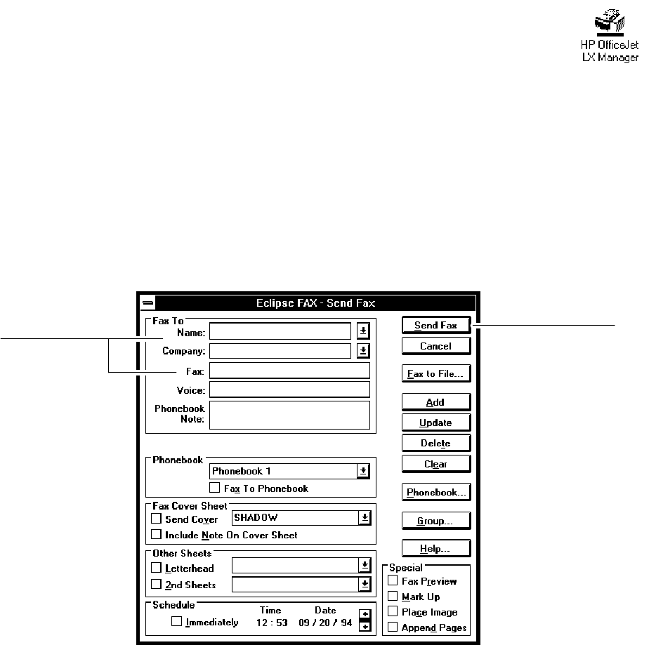
4. Use the application’s Print command to “print” the document. The Eclipse FAX SE Send Fax dialog box appears.
5. In the Send Fax dialog box,
Denter name and fax number of the intended recipients
Dthen click the Send Fax button to send it.
Name and Fax
number boxes
Send Fax button
6. When the fax is sent, you can either save your PC file or close without saving it.
For detailed information on using the Eclipse FAX SE application, refer to the HP OfficeJet LX User’s Guide.
To send paper faxes using the HP OfficeJet (LX) and not use the PC, refer to the HP OfficeJet (LX) User’s Guide.
2-9
Installation and Configuration
Receiving a Fax Directly to the PC
To receive a fax directly to the PC using Eclipse FAX SE, do the following:
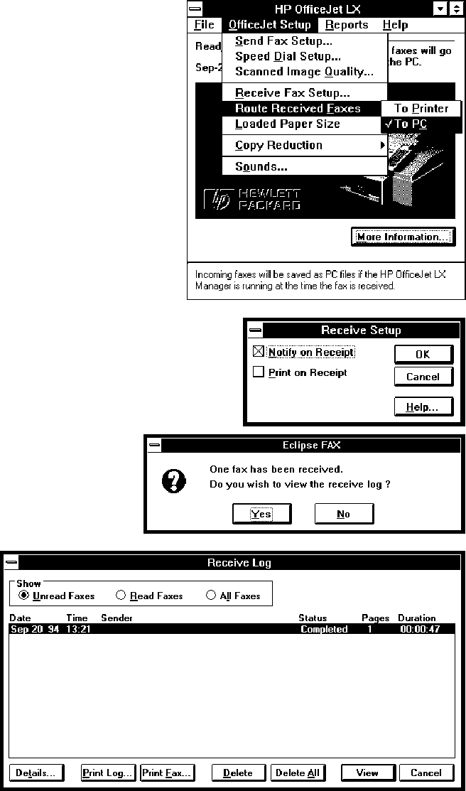
1. Open the HP OfficeJet LX Manager and make sure the
OfficeJet Setup/Route Received Faxes option is set
to To Printer.
2. Make sure that the HP OfficeJet LX Manager is running
(it can be open or minimized).
3. Make sure the OfficeJet Setup/ Route Received Faxes
option is set to To PC.
4. Open the Eclipse FAX Manager and make sure the
Notify on Receipt box is checked in the Receive/Setup
dialog box.
5. Someone sends you a fax.
A message from Eclipse FAX SE appears, noting that a fax has
been received and asking if you want to view the Receive Log.
(Notify on Receipt, which you selected in Step 4, controls
whether or not this message appears.)
6. Click the Yes button.
The Receive Log appears.
If necessary, click the
Unread Faxes button to
display the entry for the
fax you just received.
7. Highlight the entry and choose whether to print, delete, or view it.
For detailed information on using the Eclipse FAX SE application, refer to the HP OfficeJet LX User’s Guide.
To receive paper faxes using the HP OfficeJet (LX) and not use the PC, refer to the HP OfficeJet (LX) User’s Guide.
2-10 Installation and Configuration
Using Other PC Fax Programs With the HP OfficeJet LX
The user can use most Windows–based PC fax software that supports standard CAS modems with the HP OfficeJet
LX. Please note that the HP OfficeJet LX Manager must be installed and running in order to use PC fax software with
the HP OfficeJet LX.
Hewlett-Packard has tested the following packages for compatibility with the HP OfficeJet LX:
DWinFax Pro 4.0 and 3.0, from Delrina
DDataFax 3.1, from Trio
DEclipse FAX Professional 1.21 and 6.0, from Phoenix
DFaxworks Pro 3.0, from Sofnet
DUltrafax 3.1, from SoftKey
DFaxit 1.0 and 2.0, from DCA/Alien
If your installation fails for any reason, refer to the application’s installation instructions or see the “Troubleshooting”
section in the HP OfficeJet LX User’s Guide.
Note: In order to run the HP OfficeJet LX Manager and Eclipse FAX SE for PC faxing and scanning,
you must be running Windows in 386 Enhanced Mode. (To see which mode you’re running, choose
Help/About Program Manager from your Windows Program Manager menu bar.) If you have an 80386
processor with at least 2 MB of RAM, your PC should run Windows in 386 Enhanced Mode by default.
If you have a 386 PC with at least 1 MB of RAM but your PC does not run Windows 386 mode by
default, you can cause it to run in this mode by typing WIN/3 to run Windows, rather than WIN.
Installing a Control Panel Overlay
Each HP OfficeJet is shipped with a control panel overlay installed, appropriate for the country of destination for the
product. The overlay has the HP logo and OfficeJet name as well as the control panel button names printed on it. If an
overlay needs to be installed, remove the protective cover from the back of the overlay and carefully position the
overlay on the control panel. Then press the overlay into place.
Removing the Protective Cover from the Back of the Control Panel Overlay
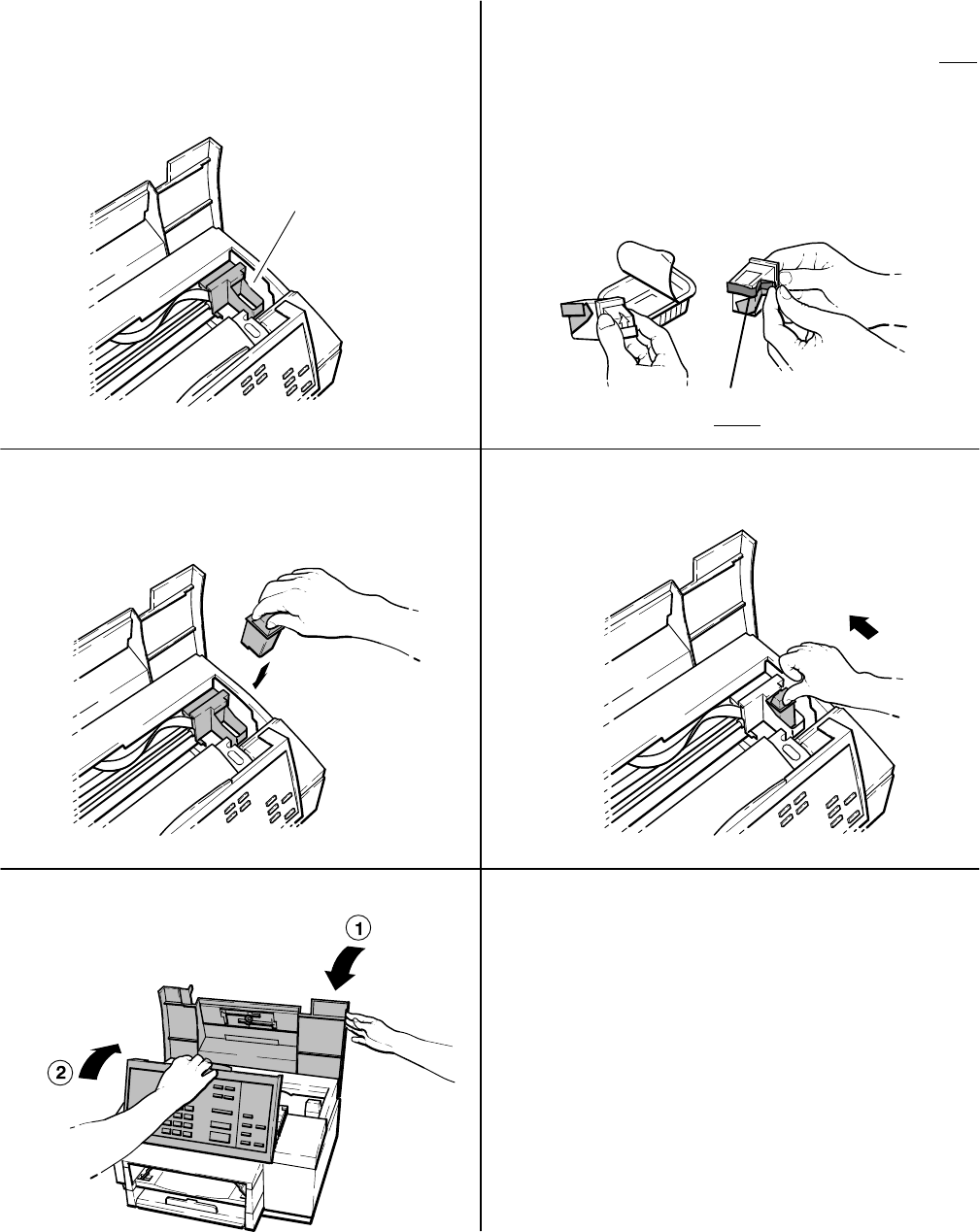
2-11
Installation and Configuration
Installing a Print Cartridge
21 With the control panel and top cover open, locate
the print cartridge cradle inside the HP OfficeJet,
near on the right side.
Print cartridge cradle
34
Open the print cartridge box and container, then
grasp the print cartridge by the green top and remove
the cartridge from the container. Gently remove both
pieces of tape – blue and white – covering the ink
nozzles and vent hole.
CAUTIONS: 1) If you don’t remove the white tape,
the cartridge will prematurely fail.
2) Be careful not to touch the ink nozzles or the
copper contacts. Fingerprints may damage them.
Place the print cartridge down into the cradle as
shown. Align the green arrow on the cartridge
top with the green dot on top of the cradle.
Remove both pieces of tape!
Push the green arrow toward the green dot until
the cartridge snaps into place.
Close the top cover, then close the control panel.
5 Helpful Hint:
Be sure to close the control panel firmly, until it
snaps into place.
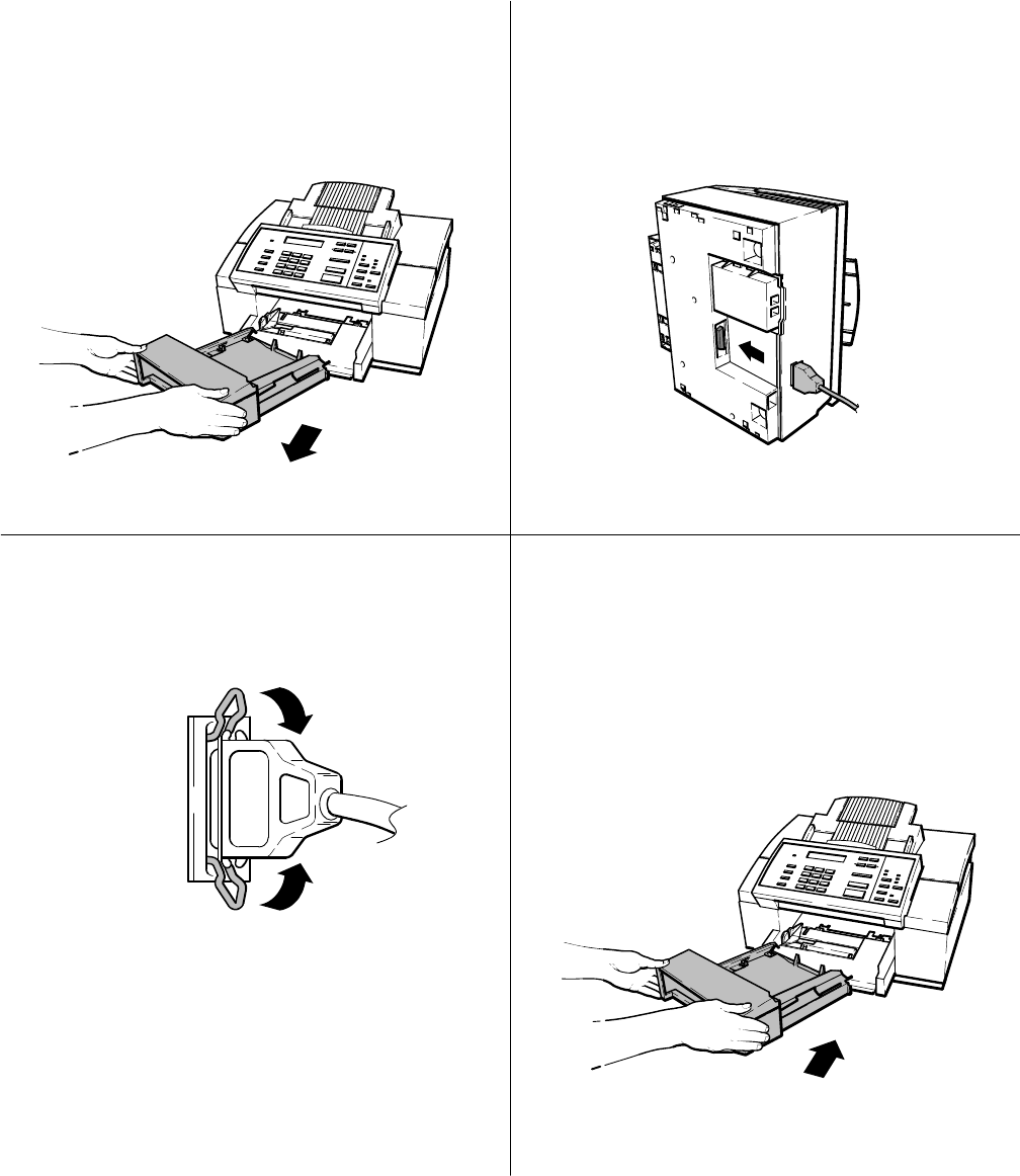
2-12 Installation and Configuration
Installing an Interface Cable for Printing
You must purchase separately a shielded Centronics parallel interface cable to connect the HP
OfficeJet to your computer for printing. You can use the HP C2950A (2 meter) or the HP
C2951A (3 meter) Centronics parallel cable. See Chapter 1 for ordering information.
Make sure your computer is turned off by pressing
“O” on the On/Off switch (located on the left side
of the machine’s base). Then remove the output
tray from the HP OfficeJet and set it aside.
21 Place the HP OfficeJet on a stable surface at a
safe distance from the edge. Then tilt and rotate
the HP OfficeJet on its side so that the bottom of
the unit faces you as shown below. Connect the
printer end* of the interface cable firmly to the
interface port on the HP OfficeJet.
3Snap both clips into the notches on the connector
as shown. 4Return the HP OfficeJet to its upright position,
making sure it does not rest on the interface cable.
Insert the output tray.
* The printer end of the interface cable has
notches, and the computer end has screws.
Now connect the computer end of the interface
cable to the parallel (LPT 1) port on your
computer and tighten the screws on the
connector (not shown).
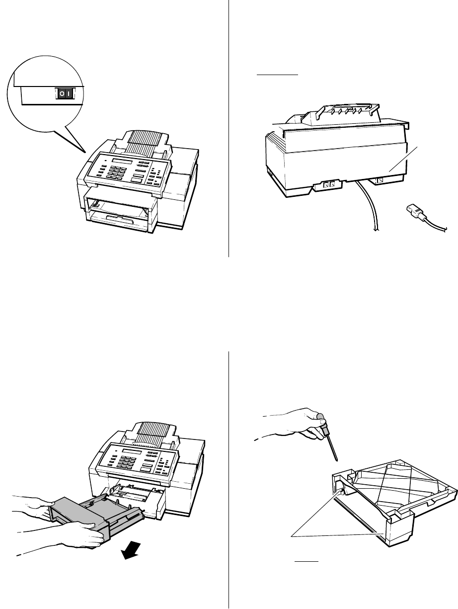
2-13
Installation and Configuration
Installing the Power Cord
Make sure the printer is turned off by pressing
“O” on the On/Off switch (located on the left side
of the machine’s base).
21 Look on the back of the HP OfficeJet and locate
the power socket. Then plug the power cord
connector firmly into the power socket.
WARNING: To avoid the possibility of electric
shock, plug the other end of the cord into a
grounded electrical outlet only.
Power
socket
Installing a Document Catch Tray (optional)
The document catch tray will hold your original documents after they have been scanned for faxing or copying.
Remove the output tray from the HP OfficeJet.
1 2 Turn over the output tray so that the bottom
faces you. Using a small Phillips-head
screwdriver, remove the two screws from the
bottom of the tray.
Remove both screws!
(Instructions are continued on next page)
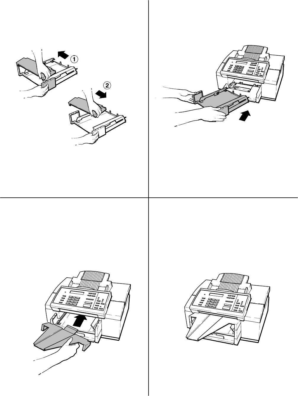
2-14 Installation and Configuration
3Remove the cover of the output tray by pushing
in on one side of the cover until it releases, then
pulling the cover in the opposite direction to
free the other side.
4Replace the output tray. Store the cover and
screws together in case you want to reinstall the
cover later.
Install the catch tray by tucking the tab
underneath the control panel area (shown
below), then placing it to rest on the outer
edges of the output tray.
65 Be sure to align the catch tray so that the
notches are inside the edges of the output tray
and the front of the catch tray is flush with the
front of the output tray. When the catch tray is
installed correctly, here’s how the HP OfficeJet
should look:
For safety purposes, the catch tray is designed to
be removed easily by lifting up on the narrow end.
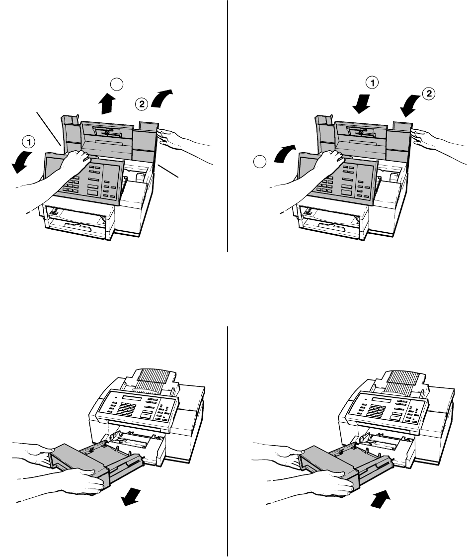
2-15
Installation and Configuration
Installing an Access Door Assembly
2
1
The access door assembly contains the document feed tray and extender and adjustable paper size guides.
Originals of faxes to be sent or documents to be copied are placed on the feed tray for processing.
The tray extender can be raised to support legal size documents being faxed or copied.
The paper size guides are adjusted to fit the size of the original document being sent or copied.
To remove the old access door assembly, lift
open the control panel assembly and raise the
access door assembly to the fully open position.
Flex out the sides of the access door near
the lower corners and lift the access door
assembly straight up to remove it.
Flex out the sides of the access door near the
lower corners and lower the new access door
assembly into place.
Close the access door and control panel
assemblies.
Be sure to close the control panel firmly, until it
snaps into place.
3
3
Flex outward
Flex outward
Installing an Output Tray
Remove the old output tray from the HP OfficeJet.
1
The output tray collects faxes, print jobs, reports and copies after they are received and printed.
2Install the new output tray into the HP OfficeJet.
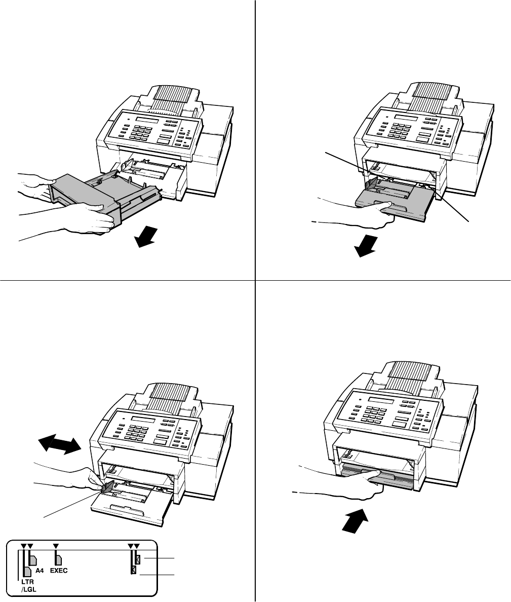
2-16 Installation and Configuration
Installing an Input Tray
The input tray is also known as the paper supply tray. This tray is where paper is loaded for the printing
of received faxes, print jobs, reports and copies. The tray holds 100 sheets of paper.
12
34
Remove the output tray from the HP OfficeJet. While pulling the input tray forward, flex the
two tabs shown, one at a time, to release each
side of the tray. If the tray does not easily release,
you may need to slide the tray in slightly, flex the
tab and then pull the tray forward again.
When installing the output tray, slide the tray
all the way into the machine.
Check the position of the paper size setting
and adjust if necessary.
Slide the green paper guide until it snaps into
place at the appropriate paper size setting.
Note: Only letter-, legal-, and A4-size paper
can be loaded for fax reception and copying.
Flex Tab
Flex Tab
Paper Guide
U.S. No. 10
envelope
European DL
envelope
Be sure to set the paper size in the menu.
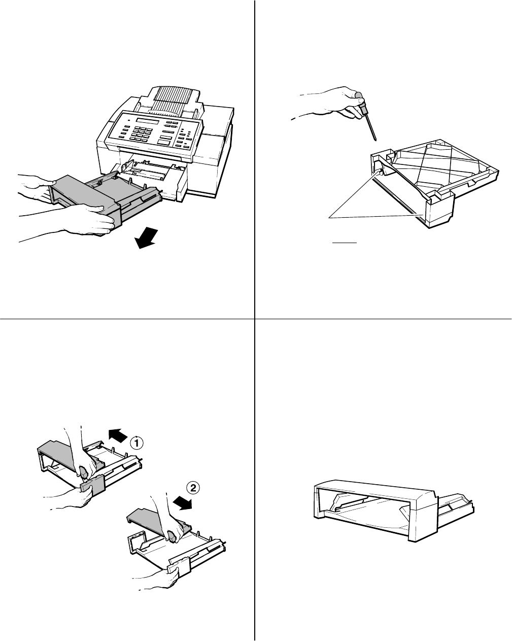
2-17
Installation and Configuration
Installing a Tray Cover
Remove the output tray from the HP OfficeJet.
12
Turn over the output tray so that the bottom
faces you. Using a small Phillips-head
screwdriver, remove the two screws from the
bottom of the tray.
Remove both screws!
34
Remove the cover of the output tray by pushing
in on one side of the cover until it releases, then
pulling the cover in the opposite direction to
free the other side.
Install the new tray cover to the output tray.
Do not over-tighten the two screws or you
could damage the screw hole threads.
When properly installed, the tray assembly
should look like the one shown here.
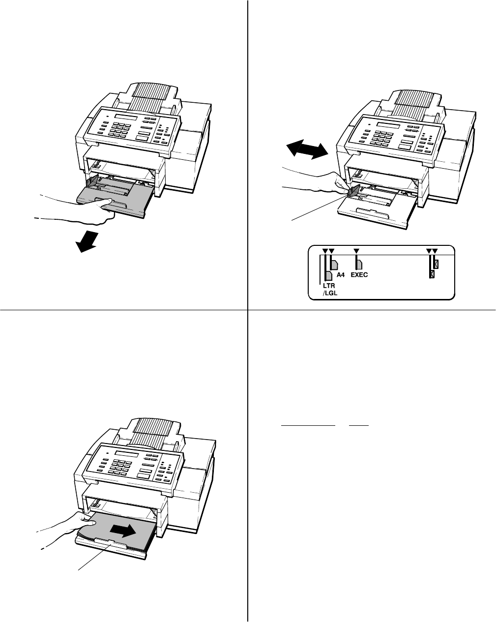
2-18 Installation and Configuration
Loading Paper in the Input (Paper) Tray
12
34
Check the position of the paper size setting
and adjust if necessary.
Slide the green paper guide until it snaps into
place at the appropriate paper size setting.
Note: Only letter-, legal-, and A4-size paper
can be loaded for fax reception and copying.
Paper Guide
Pull the input tray out until it is fully extended.
Load the paper (print side down), aligning the
right edge of the paper to the right side of the
tray. The paper stack should fit underneath the
grip on the input tray handle.
You can load up to 100 sheets (about 1 cm. or
1/2-inch thick stack) into the tray.
Input Tray Handle Grip
Helpful Hints:
Do not force the input tray all the way in when
closing it. The paper must not buckle or a paper
jam could occur.
This table lists the allowable paper sizes.
Description
Letter
A4 1
Legal
Size
8.5 x 11 inches (216 x 279 mm)
8.27 x 11.7 inches (210 x 297 mm)
8.5 x 14 inches (216 x 356 mm)
1 A4 is the standard size for letters in European countries.
Executive 27.25 x 10.5 inches (184 x 267 mm)
2You cannot make copies or receive faxes on this paper size.
Be sure to set the paper size in the menu.
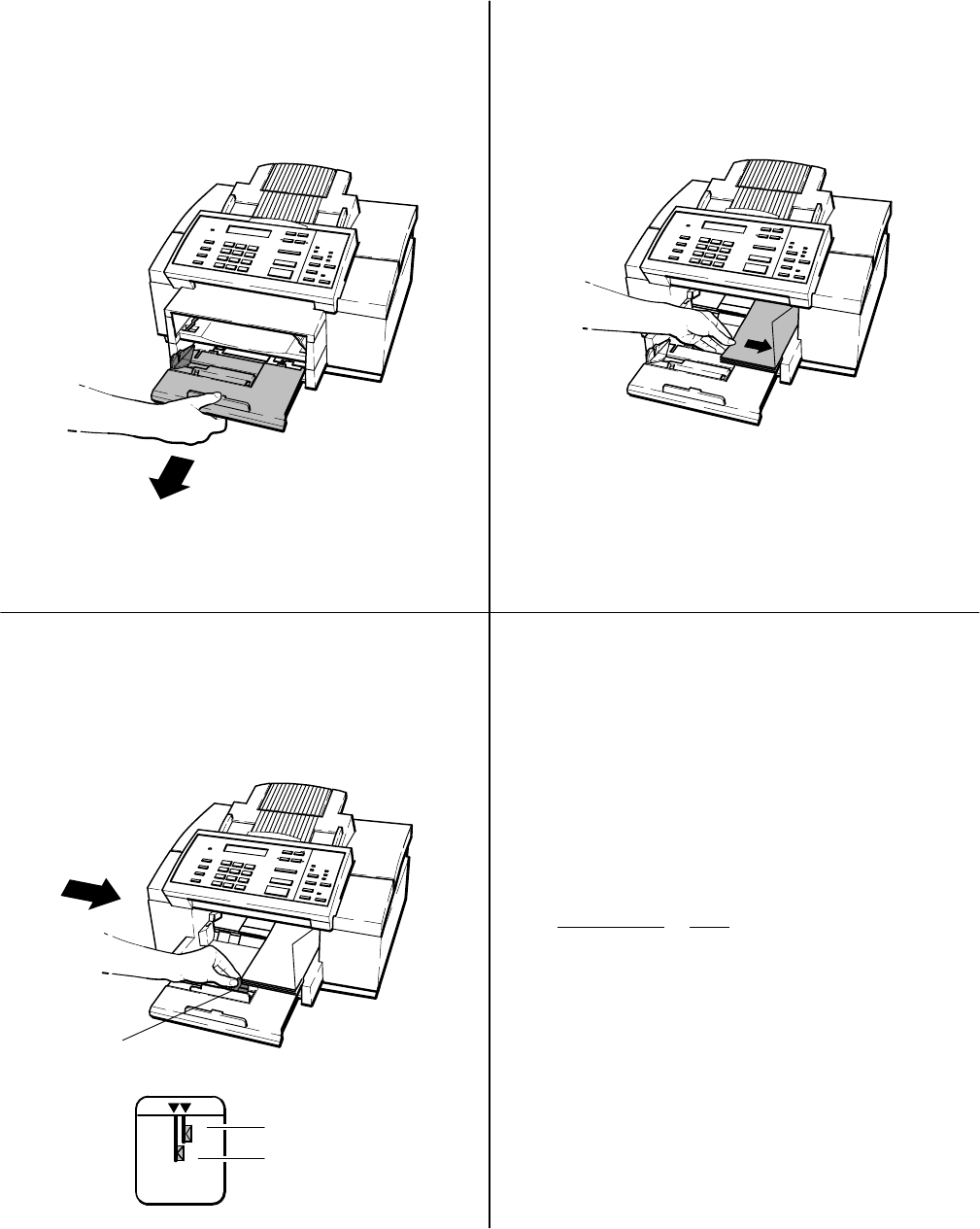
2-19
Installation and Configuration
Loading Envelopes in the Input (Paper) Tray
12
34
Slide the green paper guide until it snaps into
place at the appropriate envelope size setting.
The envelope guide will pop up to keep the
envelopes vertically aligned. Install the output
tray if not already installed.
Paper Guide
Pull the input tray out until it is fully extended.
You can remove the output tray to facilitate
envelope loading as shown in this procedure. Be sure
to install the output tray before printing.
Helpful Hints:
Do not force the input tray all the way in when
closing it. The envelopes must not buckle or a
paper jam could occur.
Load up to 20 envelopes flap up, with the
top edge aligned to the right side of the
HP OfficeJet, as shown.
U.S. No. 10
envelope
European DL
envelope
The following table lists the two allowable
envelope sizes. Note that copies cannot be
made and faxes cannot be received on any
envelopes. Be sure to set the paper size in the
menu to envelopes before printing.
Description Size
European DL
envelopes 8.66x4.33 inches (220x110mm)
U.S. No. 10
envelopes 9.5 x4.12 inches (241x105 mm)
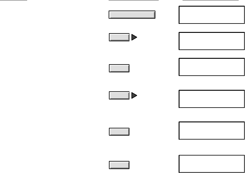
2-20 Installation and Configuration
Setting the Paper Size in the Menu
Set the paper size in the menu to match the paper size loaded in the input tray. Setting the paper size allows the
HP OfficeJet to scale incoming faxes to fit the paper size loaded. The factory setting is Letter (8 1/2 x 11
inches). If Letter size paper is loaded, no changes is required unless the menu setting was previously changed
and not reset to Letter size. If Legal or Envelope sizes are loaded, set the menu to the appropriate size.
Using
Do this: these buttons: For this display:
1. Press the Menu button to display
the menu.
Menu MENU
Time/Date, Header
2. Press Right Arrow multiple
times to move to “Paper Size.” Paper Size
3. Press Enter/Save to select “Paper
Size.” The selected paper size is
marked with an asterisk (*).
Enter/Save PAPER SIZE
Letter (8.5 x 11 in) *
Enter/Save
MENU
4. Press Right Arrow multiple times
to move to the setting you want.
(The example is “Envelopes.”)
PAPER SIZE
Envelopes
Enter/Save
6. Press Enter/Save to return to the
Ready display.
5. Press Enter/Save to select the
displayed setting. An asterisk (*)
denotes your new selection.
PAPER SIZE
Envelopes *
Ready Auto
Nov-1-94 12:32 PM
The paper size in an HP OfficeJet LX is setup during installation of the software but can be changed using the HP
OfficeJet LX Manager software by selecting the Loaded Paper Size in the OfficeJet Setup dialog box as described in
the HP OfficeJet LX User’s Guide.

2-21
Installation and Configuration
Setting Up for Printing
Using an HP OfficeJet LX with the HP OfficeJet LX Manager to control printing is briefly described earlier in this
section. Detailed and custom setup information is provided in the HP OfficeJet LX User’s Guide.
In order to use the HP OfficeJet printer function with a personal computer, the interface cable and a printer driver (also
called printer software) must be installed to make the computer and computer software work with the HP OfficeJet.
Printer drivers are software files that control the printer and allow the computer software applications to access the
printer’s features.
The HP OfficeJet will work with Microsoft Windows 3.1, OS/2 and DOS software applications. Windows and DOS
drivers are supplied with the HP OfficeJet. Install the drivers according to the instructions supplied with the drivers.
Since the HP OfficeJet is compatible with HP DeskJet 520 and 510 printers, OS/2 users can select either from the
printer model selection menu.
Note: If using both Windows and DOS applications, be sure to exit Windows before running
the DOS applications. Do not run DOS applications from the MS-DOS prompt.
Each DOS software application requires a specific printer driver. Access to some printer features such as font selection
depends on the application and driver installed.
Determine if your software application provides a printer driver that you can use.
Check the printer selection or printer setup menu in your software application for a list of printer models. The list
below identifies recommended printer driver selections you can use and the type of support that each offers:
Use this printer driver selection: For this type of printer support:
HP DeskJet 520 printer All printer features
HP DeskJet 510 printer All printer features
HP DeskJet 550C printer All printer features (except color)
HP DeskJet Portable printer All printer features except
envelope printing
HP DeskJet 500 printer All printer features except for some
fonts and envelope printing
Note: Unlike the HP DeskJet 520 printer, the HP OfficeJet cannot be used with external font
cartridges nor accept downloadable character fonts from the PC.
Select the printer driver using the instructions provided by your software application manual.
If the HP DeskJet 520 printer is not listed, use one of the alternate printer drivers listed and contact your software
company to determine if an HP DeskJet 520 printer driver is available. You could also try the HP DeskJet, HP
DeskJet+ or other HP printer driver.
Note: You may need to add or change the MODE statement in your computer’s
AUTOEXEC.BAT file. The MODE statement tells your computer where to send printing
information. This statement is not always required. If the HP OfficeJet won’t print, check your
AUTOEXEC.BAT file to make sure the MODE statement for a Centronics parallel connection
to the LPT 1 port is: MODE LPT 1:,,P If you are not familiar with your
AUTOEXEC.BAT file, see your DOS manual for information.
If the HP OfficeJet won’t print, reconnect the interface cable and try again before referring to the troubleshooting
chapter in this manual.

2-22 Installation and Configuration
Setting Up for Faxing (U.S., Australia, Canada and Mexico Installations)
Using an HP OfficeJet LX with the HP OfficeJet LX Manager and Eclipse FAX SE to control faxing is briefly
described earlier in this section. Detailed information is provided in the HP OfficeJet LX User’s Guide. Reception
mode in an HP OfficeJet LX is set during installation of the software, but can be changed using the HP OfficeJet LX
Manager software as described in the HP OfficeJet LX User’s Guide.
The following four types of installations are the ones recommended for use with the HP OfficeJet to achieve the best
call-handling results. While other situations are possible, it is recommended that one of these be used. Determine
which installation most closely meets the user’s needs and follow the instructions given.
DReceive fax calls only – no voice calls, on a dedicated fax line.
DReceive fax and voice calls at the same phone number – without an answering machine.
DReceive fax and voice calls at the same phone number – with an answering machine.
DReceive fax and voice calls on the same line with distinctive ring.
After selecting the best installation to meet the user needs, the correct reception mode and certain station specific
information will need to be set up. The procedures to accomplish this are in the following topics:
DSetting the Reception Mode for incoming calls.
DSetting the number of rings to answer.
DSelecting Tone or Pulse dialing
DEntering the Date and Time
DEntering the header information (company name and fax number).
Note:The HP OfficeJet is not supported with roll-over phone systems (such as the automatic
answering systems often used in large companies), voicemail, call waiting, and some other
advanced features provided by your phone company. If you have call waiting or other features
that can be temporarily turned off by pressing a series of buttons on your phone, we recommend
that you turn them off while sending and receiving faxes with the HP OfficeJet. Check with
your phone company if you need help.
Receive fax calls only – no voice calls, on a dedicated fax line
This installation is recommended when using a separate telephone line and number dedicated to receiving faxes only
(no voice calls). Installation consists of connecting the HP OfficeJet to the telephone wall jack with the telephone cord
provided with the machine and setting the Receive Mode to Auto. Auto receive mode is the factory default set at
shipment. If the setting was changed and you want to use Auto mode reception, you will need to set the mode to Auto.
Instructions for setting the Receive Modes are provided later in this chapter.
HP OfficeJet (LX)
Telephone Wall Jack
Cord to socket labelled “LINE”
Optional:
You can
connect a telephone
to the “TEL” socket of
the HP OfficeJet for
outgoing voice calls if
desired.
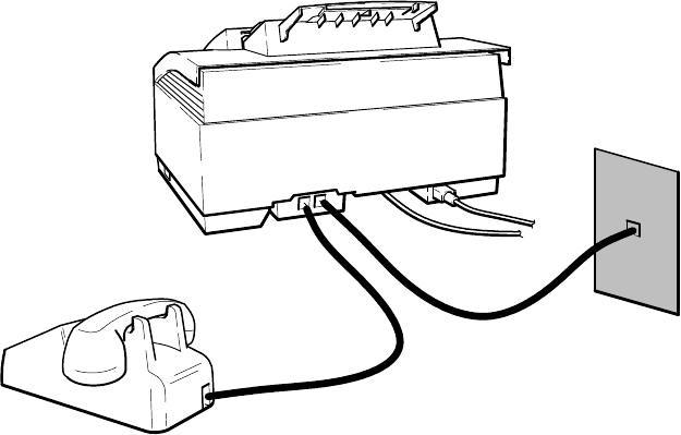
2-23
Installation and Configuration
Note: In Auto receive mode, the HP OfficeJet will pick up the line after detecting the number
of rings specified in the Rings to Answer setting and then send a fax tone signal to the calling
fax machine to start communication. The fax is then sent and the HP OfficeJet will start to
receive it. The Rings to Answer setting is user defined through the front panel menu. You can
choose from 2 to 5 rings. The factory default is 2 rings.
Receive fax and voice calls at the same phone number – without an answering machine
This installation is recommended when using one telephone number for both fax and voice calls and not using a
telephone answering machine. Installation consists of connecting the HP OfficeJet to the telephone wall jack,
connecting a telephone directly to the HP OfficeJet and setting the Receive Mode to Manual. Instructions for setting
the Receive Modes are provided later in this chapter.
HP OfficeJet (LX)
Telephone Wall Jack
Cord to socket labelled “LINE”
Cord to socket labelled “TEL”
Telephone
Note: In Manual receive mode the HP OfficeJet will never pick up the line to answer a call.
All calls must be answered manually. Voice calls are treated as normal voice calls by answering
the phone. To receive a fax, you must first answer the phone, listen for the fax tone and then
press the Start/Copy button on the front panel. For fax calls, you must use the telephone that
is directly connected to the TEL jack on the back of the HP OfficeJet. After answering the
phone and the caller notifies you that a fax is about to be sent to you, or you hear a fax tone,
press the Start/Copy button and then hang up the telephone. The fax is then sent and the HP
OfficeJet will start to receive it.
If you have a shared fax/voice line and you want to be able to receive faxes automatically, you
cannot use Manual receive mode. To receive faxes automatically, you need to either connect an
answering machine to the HP OfficeJet and use Fax/TAM receive mode or, if your phone
company has a distinctive ringing service available, you could connect your HP OfficeJet to
receive fax and voice calls on the same line with distinctive ring in Auto receive mode.
Information on using an answering machine or distinctive ring are provided later in this chapter.
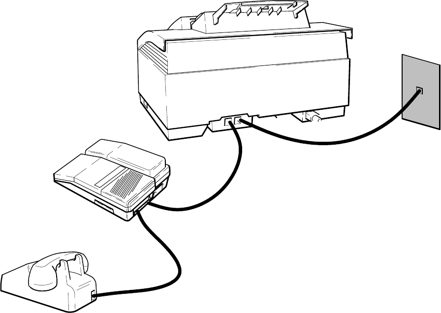
2-24 Installation and Configuration
Receive fax and voice calls at the same phone number – with an answering machine
This installation is recommended when using one telephone number for both fax and voice calls and using a telephone
answering machine. Installation consists of connecting the HP OfficeJet to the telephone wall jack, connecting a
telephone answering machine directly to the HP OfficeJet and setting the Receive Mode to Fax/TAM. Instructions for
setting the Receive Mode are provided later in this chapter. Two scenarios are possible when using an answering
machine – one where the telephone handset is an attached part of the answering machine and one where the telephone
is a separate item that must be connected to the answering machine that is directly connected to the HP OfficeJet. Both
scenarios are depicted in the following diagram.
Cord to socket labelled “LINE”
Cord to socket labelled “TEL”
Telephone To Telephone Answering Machine socket labelled “TEL”
To Telephone Answering Machine socket labelled “Line” or “Wall”
HP OfficeJet (LX)
Telephone Wall Jack
For use with separate telephone if the phone
handset is not part of the answering machine
Answering Machine
Note: In Fax/TAM receive mode the answering machine attached to the HP OfficeJet will
answer all incoming calls and begin the outgoing message recorded on the answering machine
tape. The HP OfficeJet will not pick up the line. During the outgoing message, the HP OfficeJet
will monitor the incoming line for a fax tone signal. If the HP OfficeJet detects a fax tone
signal, it will automatically take over the call and start to communicate with the calling fax
machine to receive the fax. If a fax tone signal is not detected, the answering machine accepts
the voice call and records the message.
Some older fax machines may not emit a fax calling tone. In this case the silent detect feature in
the HP OfficeJet must be used in order to take the fax call. This feature is accessed through the
front panel menu as described in the HP OfficeJet User’s Guide, and should only be used when
receiving a fax from an old model fax machine.
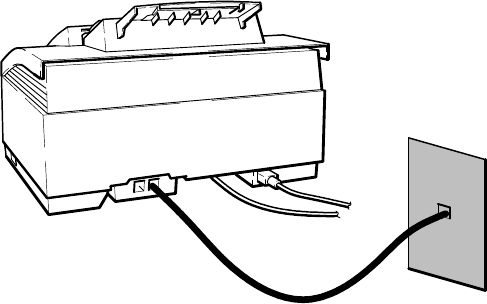
2-25
Installation and Configuration
Receive fax and voice calls on the same line with distinctive ring
This installation is recommended when using one telephone number for both fax and voice calls and using a
distinctive ringing service through the local telephone company. The telephone company’s distinctive ring service
allows the use of 2 or 3 phone numbers on the same phone line. The HP OfficeJet, however, will only accept up to 2
numbers on a single line. Each of the phone numbers will have a distinctive ringing pattern: The first phone number
will have a single ring (ring) and the second will have a double ring (ring-ring) pattern. When activated, the HP
OfficeJet distinctive ring feature can use the ring patterns to distinguish between fax and voice calls received on the
same line. The feature will need to be set to ON in the OfficeJet if distinctive ring is to be used. If not used, the feature
must be deactivated. Factory default for the feature is OFF.
Note: The distinctive ring feature is not available in all local telephone system networks.
Currently, only certain U.S. regions and some Asian countries offer the service. The local
telephone company should be contacted for availability of the service.
This application can be used either with or without an answering machine attached to the HP OfficeJet. Installation
and setup for use of distinctive ring is as follows:
1. Connect the HP OfficeJet to the telephone wall jack.
2. If an answering machine is to be used, connected it to the HP OfficeJet, or to a separate wall jack.
3. Set the HP OfficeJet Receive Mode to Auto, or fax calls will not be received.
4. Also, if connecting an answering machine for voice calls on this line, make sure the setting on the answering
machine that controls the number of rings before answering is set to a number greater than the Rings to Answer
setting on the HP OfficeJet. For example, if the HP OfficeJet is set to 2 rings to answer, set the answering machine to 3
or more rings to answer. CAUTION: If you don’t do this, you may not receive your fax calls properly. Instructions on
setting the Receive Mode and HP OfficeJet Rings to Answer number are given later in this chapter.
Optional:
You can connect
a telephone or answering
machine* to the “TEL”
socket of the HP OfficeJet.
HP OfficeJet (LX)
Telephone Wall Jack
Cord to socket labelled “LINE”
Note: If using the telephone company’s distinctive ring service, have the single-ring assigned to
the phone number at which voice calls are to be received and the multiple-rings assigned to the
phone number(s) at which the fax calls are to be received. When the HP OfficeJet’s Distinctive
Ring feature is set to On, it will only answer the phone and receive faxes when it detects any
multiple ring pattern.
The factory default setting for the HP OfficeJet distinctive ring feature is OFF. The feature should not be set to ON
unless the user has already subscribed to the telephone company’s distinctive ring service. If set to ON before service
is established, the HP OfficeJet will not receive faxes automatically.
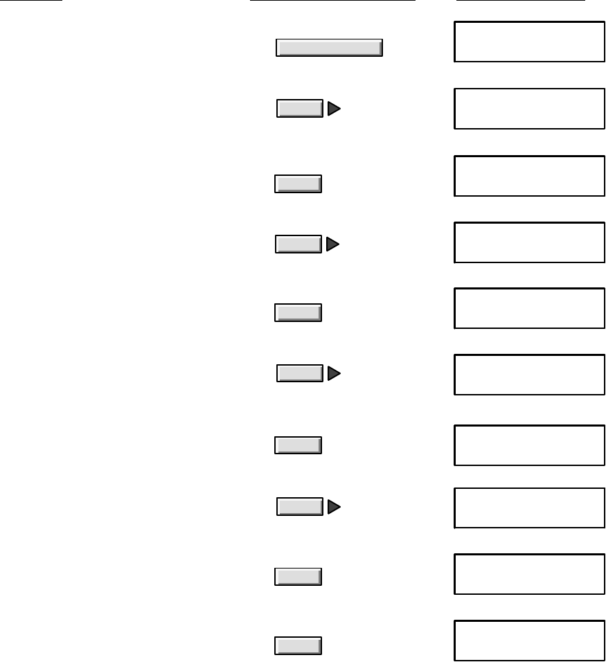
2-26 Installation and Configuration
Distinctive Ring in an HP OfficeJet LX is set OFF, but can be set ON using the HP OfficeJet LX Manager software by
selecting the Distinctive Ring in the Receive Fax Setup dialog box as described in the HP OfficeJet LX User’s Guide.
To set the HP OfficeJet distinctive ring feature to ON, use the following instructions:
Do this: Using these buttons: For this display:
a. Press the Menu button to display the menu. Menu
b. Press Right Arrow multiple times to move to
“Fax Settings.”
Enter/Save
MENU
Fax Settings
MENU
Time/Date, Header
c. Press Enter/Save to select “Fax Settings.” FAX SETTINGS
Speed Dial Setup
d. Press Right Arrow multiple times to move to
“Phone Setup.” FAX SETTINGS
Phone Setup
DISTINCTIVE RING
Off *
Enter/Save
i. Press Enter/Save to select the displayed setting.
An asterisk (*) denotes your new selection. DISTINCTIVE RING
On *
g. Press Enter/Save to select “Distinctive Ring.”
Note that an asterisk (*) denotes the current
selection.
h. Press Right Arrow to move to the setting
you want. DISTINCTIVE RING
On
Enter/Save
j. Press Enter/Save again to return to the
Ready display.
Ready Auto
Sep-21-94 12:45 PM
Enter/Save
e. Press Enter/Save to select “Phone Setup.” PHONE SETUP
Rings to Answer
f. Press Right Arrow multiple times to move to
“Distinctive Ring.” PHONE SETUP
Distinctive Ring
Enter/Save
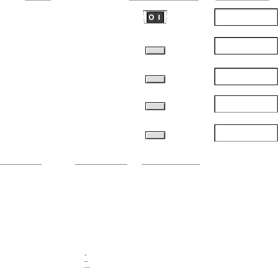
2-27
Installation and Configuration
Setting the Reception Mode for Incoming Calls
The Reception Mode affects how the HP OfficeJet answers incoming fax and voice calls. Use the following instructions to
change the Reception Mode setting. Reception mode in an HP OfficeJet LX is set during installation of the software, but
can be changed using the HP OfficeJet LX Manager software by selecting the Receive Mode in the Receive Fax Setup
dialog box as described in the HP OfficeJet LX User’s Guide. The table describes the three Receive Mode settings (Auto,
Manual, and Fax/TAM) and when to use them.
2. Press the Receive Mode button to display
the current Receive Mode setting, which is
marked with an asterisk (*). (The example
shown is Auto, the factory setting.)
Receive Mode
RECEIVE MODE
Fax/TAM
3. Press Receive Mode multiple times to get to
the appropriate setting (see the following table).
(“Fax/TAM,” shown at right, is only an example.)
RECEIVE MODE
Auto *
Receive Mode
4. Press Enter/Save to select the displayed setting.
Note that an asterisk (*) denotes the new selection.
5. Press Enter/Save again to return to the Ready
display. Note that the Receive Mode selected is
displayed on the top line next to “Ready.”
Enter/Save
Enter/Save
RECEIVE MODE
Fax/TAM *
Ready Fax/TAM
Jan-31-94 12:32 PM
1. Make sure the HP OfficeJet is turned on. Ready Auto
Jan-31-94 12:30 PM
Do this: Using these buttons: For this display:
If you have this Set the
type of setup: Receive Mode to: And read this note:
Dedicated fax line
(receives only fax calls) Auto
Shared fax/voice line,
no answering machine,
telephone connected
to HP OfficeJet
Manual
Shared fax/voice line,
with answering machine Fax/TAM
(TAM means
telephone
answering
machine)
Shared fax/voice line,
with Distinctive Ring
feature (with or without
an answering machine)
Auto
When Auto is selected with a dedicated fax line, the
HP OfficeJet answers all incoming calls after the
number of rings specified in the Rings to Answer
setting and sends out fax reception tones to receive
a fax.
When Manual is selected, the HP OfficeJet never
answers incoming calls. To receive a fax, pick up the
handset of the phone connected to the HP OfficeJet,
press the Start/Copy button, then hang up the
phone.
When Auto is selected and you have subscribed to a
distinctive ring feature through your phone company,
the HP OfficeJet will only answer incoming calls with
any multiple-ringing pattern.
When Fax/TAM is selected, the answering machine
answers all calls (after the number of rings specified
on that device), and the HP OfficeJet automatically
takes over the line when a fax tone is detected.
Notes: 1) This setting will not work unless you have
connected an answering machine
directly
to the HP
OfficeJet. 2) For best results, limit the greeting
message on the answering machine to 10 seconds.
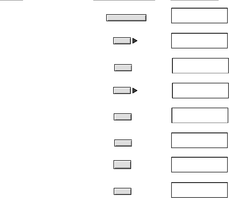
2-28 Installation and Configuration
Setting the Number of Rings to Answer
The number of rings setting is ONLY used when the HP OfficeJet is used in the Auto Receive Mode. This setting is
used to determine the number of rings sensed before the HP OfficeJet answers a call. Although the range of rings may
vary for different countries, in the U.S.A., up to 5 rings can be set. The factory default setting is 2 rings. The number of
rings to answer in an HP OfficeJet LX is set during installation of the software, but can be changed using the HP
OfficeJet LX Manager software by setting the Rings to Answer in the Receive Fax Setup dialog box as described in the
HP OfficeJet LX User’s Guide.
2. Press Right Arrow multiple times to move
to “Fax Settings.”
3. Press Enter/Save to select “Fax Settings.” Enter/Save
Enter/Save
8. Press Enter/Save to save the new value and
return to the Ready display.
MENU
Fax Settings
FAX SETTINGS
Speed Dial Setup
Ready Auto
Jan-31-94 12:36 PM
1. Press the Menu button to display the Menu. MENU
Time/Date, Header
Menu
4. Press Right Arrow multiple times to move
to “Phone Setup.” FAX SETTINGS
Phone Setup
5. Press Enter/Save to select “Phone Setup.”
(“Rings to Answer” is displayed.)
PHONE SETUP
Rings to Answer
Enter/Save
6. Press Enter/Save to select “Rings to
Answer.” The allowable range (in brackets)
and the factory setting (far right) are displayed.
Rings to Answer
[2-5] 2
Enter/Save
7. Enter a number up to 5, inclusive.
(The example shows that 5 has been entered.) Rings to Answer
[2-5] 5
5
Do this: Using these buttons: For this display:
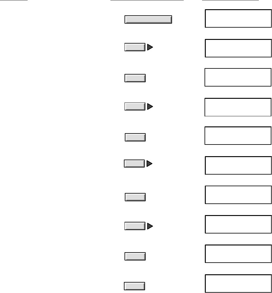
2-29
Installation and Configuration
Selecting Tone or Pulse Dialing
The HP OfficeJet is factory set for touchtone (Tone) dialing telephone systems. If used with a rotary (Pulse) dialing
telephone system, the HP OfficeJet will need to be set for Pulse dialing. This procedure can be used to set for either
dialing system as required. The dialing mode in an HP OfficeJet LX is set during installation of the software, but can be
changed using the HP OfficeJet LX Manager software by selecting Tone or Pulse in the Dialing Mode menu of the
Send Fax Setup dialog box as described in the HP OfficeJet LX User’s Guide.
2. Press Right Arrow multiple times to move
to “Fax Settings.”
3. Press Enter/Save to select “Fax Settings.” Enter/Save
Enter/Save
9. Press Enter/Save to select “Pulse.” An
asterisk (*) denotes your new selection.
MENU
Fax Settings
FAX SETTINGS
Speed Dial Setup
1. Press the Menu button to display the menu. MENU
Time/Date, Header
Menu
4. Press Right Arrow multiple times to move
to “Phone Setup.”
FAX SETTINGS
Phone Setup
5. Press Enter/Save to select “Phone Setup.” PHONE SETUP
Rings to Answer
Enter/Save
7. Press Enter/Save to select “Dialing Mode.”
The factory setting, Tone, is displayed.
DIALING MODE
Tone *
Enter/Save
8. Press Right Arrow to move to “Pulse.”
6. Press Right Arrow multiple times to move
to “Dialing Mode.”
PHONE SETUP
Dialing Mode
Enter/Save
10.Press Enter/Save again to return to the
Ready display.
Ready Fax/TAM
Jan-31-94 12:41 PM
DIALING MODE
Pulse
DIALING MODE
Pulse *
Do this: Using these buttons: For this display:
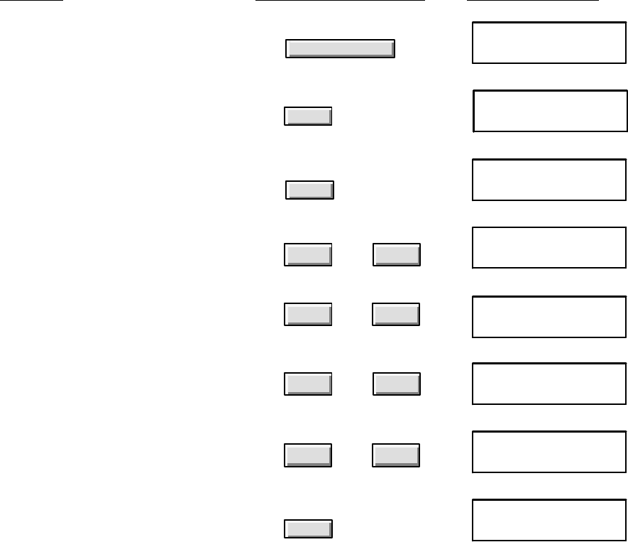
2-30 Installation and Configuration
Entering the Date and Time
Date and Time entries are required on all outgoing faxes. The fax log report will also reflect the date and time of
transactions for reference. When entering the information, the current date and time should be entered for accurate
reports and tracking of transactions. The date and time information in an HP OfficeJet LX is set during installation of the
software, but can be changed using the HP OfficeJet LX Manager software by selecting the Send Fas Setup dialog box
and entering the information as described in the HP OfficeJet LX User’s Guide.
Note: The Telephone Protection Act of 1991 requires that all faxes transmitted in the U.S.A.
display the date and time they are sent in a header, footer or cover page. Most applications
contain the information in the document header.
The date and time can be entered using this procedure.
2. Press Enter/Save to select “Time/Date,
Header.” (“Time/Date” is displayed.)
3. Press Enter/Save to select “Time/Date.” Enter/Save
TIME/DATE, HEADER
Time/Date
Enter time format
1=AM/PM 2=24-hour
1. Press the Menu button to display the menu.
(“Time/Date, Header” is displayed.) MENU
Time/Date, Header
Menu
4. Press “1” if you want to enter the time in
AM/PM format, or press “2” to enter the
time in 24-hour format. (The example shows
the AM/PM format.)
Enter time
12:46 PM
5. Enter the current time in the format you
selected. (Example shows AM/PM format.)
Press the Backspace button to correct any
mistakes.
Enter date
01-31-94
6. If you chose AM/PM format, you will be
prompted to select AM or PM after entering
the time. Press “1” to select AM or “2” to
select PM.
Enter/Save
12
or
09
through Enter 1=AM 2=PM
08:05 PM
12
or
Enter/Save
8. Press Enter/Save to save the date
you entered.
7. Enter the current date in month-day-year
format.
Ready Fax/TAM
Sep-20-94 08:05 AM
Enter date
09-20-94
09
through
Do this: Using these buttons: For this display:
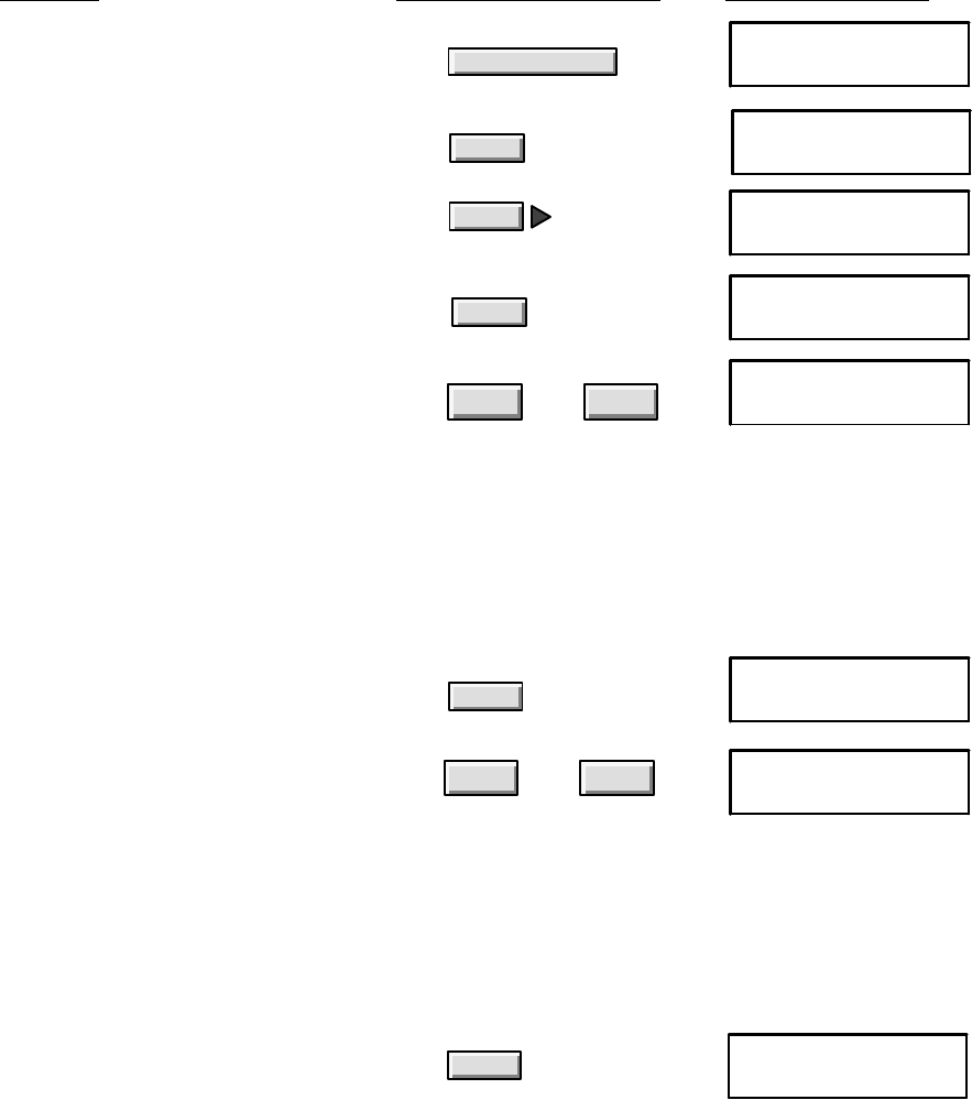
2-31
Installation and Configuration
Entering the Header Information (company name and fax number)
Sender Identification and fax number entries are required on all outgoing faxes. This information will appear in the
header of transactions for reference. The header information in an HP OfficeJet LX is set during installation of the
software, but can be changed using the HP OfficeJet LX Manager software by selecting the Send Fas Setup dialog box
and entering the information as described in the HP OfficeJet LX User’s Guide.
Note: The Telephone Protection Act of 1991 requires that all faxes transmitted in the U.S.A.
display the sender’s identifying name and fax number in a header, footer or cover page. Most
applications contain the information in the document header.
Use this procedure to enter the information.
2. Press Enter/Save to select “Time/Date,
Header.”
3. Press Right Arrow to move to “Fax Header.”
TIME/DATE, HEADER
Time/Date
TIME/DATE, HEADER
Fax Header
1. Press the Menu button to display the menu.
“Time/Date, Header” is displayed.
MENU
Time/Date, Header
Menu
4. Press Enter/Save to select “Fax Header.” Enter header name
Enter/Save
Enter/Save
Do this: Using these buttons: For this display:
5. Type the name you want displayed in the
header of your outgoing faxes, using these
guidelines:
ABC WXYZ
through
29
•Enter up to 25 characters, including letters, symbols, and spaces.
•Use the number buttons 2 through 9 to enter the lowercase and uppercase letters shown above the buttons.
•After entering a character, use Right Arrow to move the cursor to the right before entering the next
character.
•Use the Space button to enter a space.
•Use the Symbols button to enter punctuation and symbols, such as a period (.), an asterisk (*), or an at
sign (@).
Enter header name
ACME Co.
6. Press Enter/Save to save the name you typed. Enter header number
Enter/Save
7. Enter the telephone number of the fax line
you’ve connected to your HP OfficeJet using
these guidelines:
Enter header number
619 555–1234
0through 9
•Up to 20 characters are allowed, including numbers, spaces, dashes (–), and the plus sign (+).
•Use the Space button to enter a space.
•Use the Redial/Pause button to enter a 2-second pause, indicated by a dash (–).
•Use the Symbols button to enter a plus sign (+) before the country code when dialing your fax number
from another country. (For example, +1 619 555–1234.) The country code for the U.S. and Canada is 1.
For more information about international calls, contact the telephone company.
8. Press Enter/Save to save the fax number
you entered and return to the Ready display.
Enter/Save Ready Fax/TAM
Sep-20-94 08:15 AM
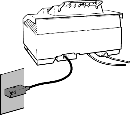
2-32 Installation and Configuration
Setting Up for Faxing (U.K. Installation)
The following types of installations are the ones recommended for use with the HP OfficeJet LX to achieve the best
call-handling results. While other situations are possible, it is recommended that one of these be used. Determine
which installation most closely meets the user’s needs and follow the instructions given.
DReceive fax calls only – no voice calls, on a dedicated fax line.
DReceive fax and voice calls at the same phone number – without an answering machine.
DReceive fax and voice calls at the same phone number – with an answering machine.
After selecting the best installation to meet the user needs, the correct reception mode and certain station specific
information will need to be set up. The procedures to accomplish this are in the following topics which are presented
in the HP OfficeJet LX User’s Guide:
DSetting the Reception Mode for incoming calls.
DSetting the number of rings to answer.
DSelecting Tone or Pulse dialing
DEntering the Date and Time
DEntering the header information (company name and fax number).
Refer to the HP OfficeJet LX User’s Guide for use with the Mercury Telephone Network System.
Using an HP OfficeJet LX with the HP OfficeJet LX Manager and Eclipse FAX SE to control faxing is briefly
described earlier in this section. Detailed information is provided in the HP OfficeJet LX User’s Guide. Reception
mode in an HP OfficeJet LX is set during installation of the software, but can be changed using the HP OfficeJet LX
Manager software by selecting the Receive Mode in the Receive Fax Setup dialog box as described in the HP OfficeJet
LX User’s Guide.
Receive fax calls only – no voice calls, on a dedicated fax line
This installation is recommended when using a separate telephone line and number dedicated to receiving faxes only
(no voice calls). Installation consists of connecting the HP OfficeJet to the telephone wall jack using the telephone
cord provided, and setting the Receive Mode to Auto. Refer to the HP OfficeJet LX User’s Guide.
HP OfficeJet LX
Telephone Wall Jack
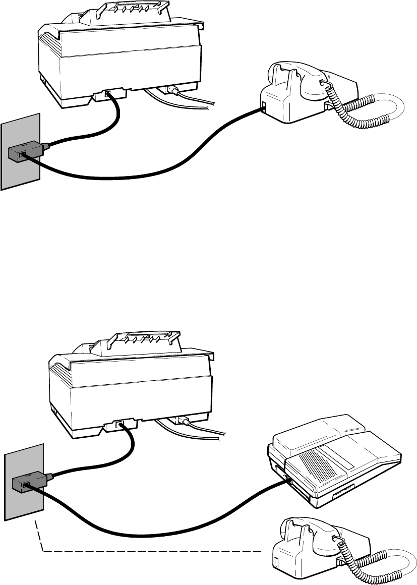
2-33
Installation and Configuration
Receive fax and voice calls at the same phone number – without an answering machine
This installation is recommended when using one telephone number for both fax and voice calls and not using a
telephone answering machine. Installation consists of connecting the HP OfficeJet LX to the telephone wall jack,
connecting the telephone directly to the HP OfficeJet LX wall jack connector as shown, and setting the Receive Mode
to Manual. Refer to the HP OfficeJet LX User’s Guide.
HP OfficeJet LX
Telephone Wall Jack
Telephone
Receive fax and voice calls at the same phone number – with an answering machine
This installation is recommended when using one telephone number for both fax and voice calls and using a telephone
answering machine. Installation consists of connecting the HP OfficeJet LX to the telephone wall jack, connecting the
telephone answering machine directly to the HP OfficeJet LX wall jack connector as shown, and setting the Receive
Mode to Fax/TAM. Refer to the HP OfficeJet LX User’s Guide. Two scenarios are possible when using an answering
machine – one where the telephone handset is an attached part of the answering machine and one where the telephone
is a separate item that must be connected following the answering machine. Both scenarios are depicted in the
following diagram.
Telephone
HP OfficeJet LX
Telephone Wall Jack
For use with separate telephone if the phone handset is not part
of the answering machine, attach after the answering machine
cord is connected
Answering Machine
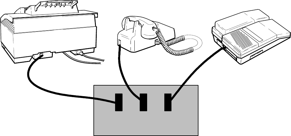
2-34 Installation and Configuration
Setting Up for Faxing (Germany Installation)
The following types of installations are the ones recommended for use with the HP OfficeJet LX to achieve the best
call-handling results. While other situations are possible, it is recommended that one of these be used. Determine
which installation most closely meets the user’s needs and follow the instructions given.
DReceive fax calls only – no voice calls, on a dedicated fax line.
DReceive fax and voice calls at the same phone number – without an answering machine.
DReceive fax and voice calls at the same phone number – with an answering machine.
After selecting the best installation to meet the user needs, the correct reception mode and certain station specific
information will need to be set up. The procedures to accomplish this are in the following topics which are presented
in the HP OfficeJet LX User’s Guide:
DSetting the Reception Mode for incoming calls.
DSetting the number of rings to answer.
DSelecting Tone or Pulse dialing
DEntering the Date and Time
DEntering the header information (company name and fax number).
Refer to the HP OfficeJet LX User’s Guide for use in a PBX system.
Using an HP OfficeJet LX with the HP OfficeJet LX Manager and Eclipse FAX SE to control faxing is briefly
described earlier in this section. Detailed information is provided in the HP OfficeJet LX User’s Guide. Reception
mode in an HP OfficeJet LX is set during installation of the software, but can be changed using the HP OfficeJet LX
Manager software by selecting the Receive Mode in the Receive Fax Setup dialog box as described in the HP OfficeJet
LX User’s Guide.
The three types of installation recommended can be depicted in the same diagram as shown below. Each device is
attached directly to the wall jack and specific N-F-N slot as shown. Installation consists of connecting the HP
OfficeJet, answering machine and telephone directly to the telephone wall jack as shown. Set the Receive Mode as
specified in the HP OfficeJet LX User’s Guide.
Telephone
HP OfficeJet LX
Telephone Wall Jack
Answering Machine
NFN
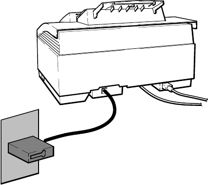
2-35
Installation and Configuration
Setting Up for Faxing (France Installation)
The following types of installations are the ones recommended for use with the HP OfficeJet LX to achieve the best
call-handling results. While other situations are possible, it is recommended that one of these be used. Determine
which installation most closely meets the user’s needs and follow the instructions given.
DReceive fax calls only – no voice calls, on a dedicated fax line.
DReceive fax and voice calls at the same phone number – without an answering machine.
DReceive fax and voice calls at the same phone number – with an answering machine.
After selecting the best installation to meet the user needs, the correct reception mode and certain station specific
information will need to be set up. The procedures to accomplish this are in the following topics which are presented
in the HP OfficeJet LX User’s Guide:
DSetting the Reception Mode for incoming calls.
DSetting the number of rings to answer.
DSelecting Tone or Pulse dialing
DEntering the Date and Time
DEntering the header information (company name and fax number).
Using an HP OfficeJet LX with the HP OfficeJet LX Manager and Eclipse FAX SE to control faxing is briefly
described earlier in this section. Detailed information is provided in the HP OfficeJet LX User’s Guide. Reception
mode in an HP OfficeJet LX is set during installation of the software, but can be changed using the HP OfficeJet LX
Manager software by selecting the Receive Mode in the Receive Fax Setup dialog box as described in the HP OfficeJet
LX User’s Guide.
Receive fax calls only – no voice calls, on a dedicated fax line
This installation is recommended when using a separate telephone line and number dedicated to receiving faxes only
(no voice calls). Installation consists of connecting the HP OfficeJet to the telephone wall jack using the telephone
cord provided, and setting the Receive Mode to Auto. Refer to the HP OfficeJet LX User’s Guide.
HP OfficeJet LX
Telephone Wall Jack
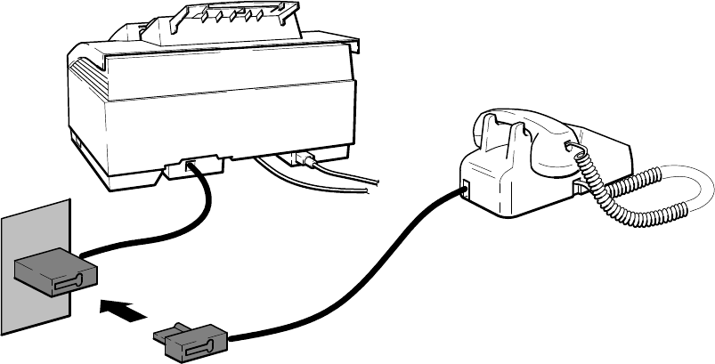
2-36 Installation and Configuration
Receive fax and voice calls at the same phone number – without an answering machine
This installation is recommended when using one telephone number for both fax and voice calls and not using a
telephone answering machine. Installation consists of connecting the HP OfficeJet LX to the telephone wall jack,
connecting the telephone directly to the HP OfficeJet LX wall jack connector as shown, and setting the Receive Mode
to Manual. Refer to the HP OfficeJet LX User’s Guide.
HP OfficeJet LX
Telephone Wall Jack
Telephone
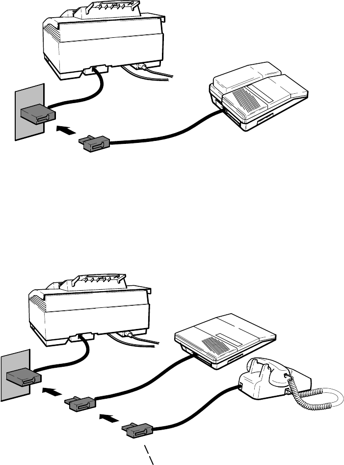
2-37
Installation and Configuration
Receive fax and voice calls at the same phone number – with an answering machine
This installation is recommended when using one telephone number for both fax and voice calls and using a telephone
answering machine. Installation consists of connecting the HP OfficeJet LX to the telephone wall jack, connecting the
telephone answering machine directly to the HP OfficeJet LX wall jack connector as shown, and setting the Receive
Mode to Fax/TAM. Refer to the HP OfficeJet LX User’s Guide. Two scenarios are possible when using an answering
machine – one where the telephone handset is an attached part of the answering machine and one where the telephone
is a separate item that must be connected following the answering machine. Both scenarios are depicted in the
following diagram.
Telephone
HP OfficeJet LX
Telephone Wall Jack
For use with separate telephone if the phone handset
is not part of the answering machine, attach after the
answering machine cord is connected
Answering Machine
HP OfficeJet LX
Telephone Wall Jack Answering Machine with
attached handset
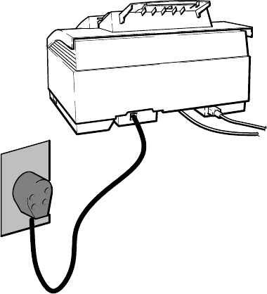
2-38 Installation and Configuration
Setting Up for Faxing (Netherlands Installation)
The following types of installations are the ones recommended for use with the HP OfficeJet LX to achieve the best
call-handling results. While other situations are possible, it is recommended that one of these be used. Determine
which installation most closely meets the user’s needs and follow the instructions given.
DReceive fax calls only – no voice calls, on a dedicated fax line.
DReceive fax and voice calls at the same phone number – without an answering machine.
DReceive fax and voice calls at the same phone number – with an answering machine.
After selecting the best installation to meet the user needs, the correct reception mode and certain station specific
information will need to be set up. The procedures to accomplish this are in the following topics which are presented
in the HP OfficeJet LX User’s Guide:
DSetting the Reception Mode for incoming calls.
DSetting the number of rings to answer.
DSelecting Tone or Pulse dialing
DEntering the Date and Time
DEntering the header information (company name and fax number).
Using an HP OfficeJet LX with the HP OfficeJet LX Manager and Eclipse FAX SE to control faxing is briefly
described earlier in this section. Detailed information is provided in the HP OfficeJet LX User’s Guide. Reception
mode in an HP OfficeJet LX is set during installation of the software, but can be changed using the HP OfficeJet LX
Manager software by selecting the Receive Mode in the Receive Fax Setup dialog box as described in the HP OfficeJet
LX User’s Guide.
Receive fax calls only – no voice calls, on a dedicated fax line
This installation is recommended when using a separate telephone line and number dedicated to receiving faxes only
(no voice calls). Installation consists of connecting the HP OfficeJet to the telephone wall jack using the telephone
cord provided, and setting the Receive Mode to Auto. Refer to the HP OfficeJet LX User’s Guide.
HP OfficeJet LX
Telephone Wall Jack
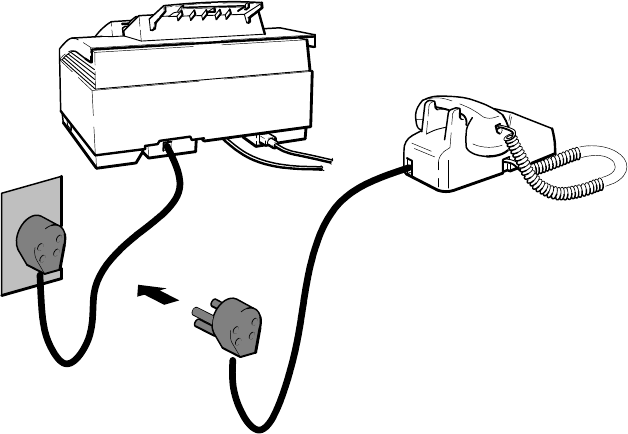
2-39
Installation and Configuration
Receive fax and voice calls at the same phone number – without an answering machine
This installation is recommended when using one telephone number for both fax and voice calls and not using a
telephone answering machine. Installation consists of connecting the HP OfficeJet LX to the telephone wall jack,
connecting the telephone directly to the HP OfficeJet LX wall jack connector as shown, and setting the Receive Mode
to Manual. Refer to the HP OfficeJet LX User’s Guide.
HP OfficeJet LX
Telephone Wall Jack
Telephone
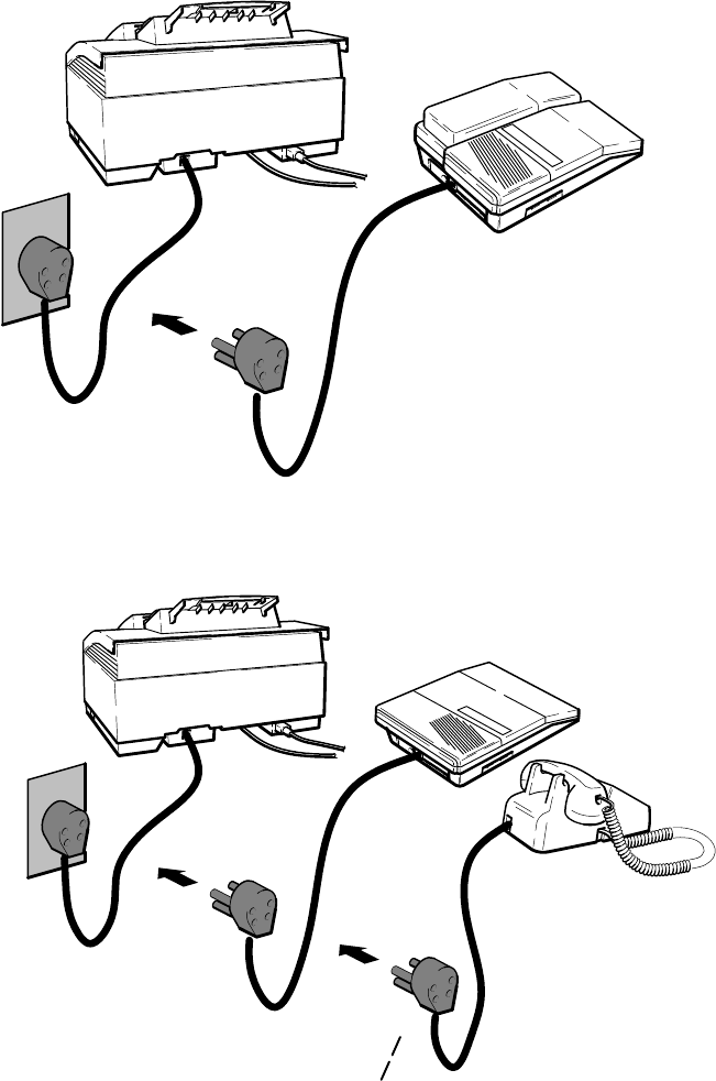
2-40 Installation and Configuration
Receive fax and voice calls at the same phone number – with an answering machine
This installation is recommended when using one telephone number for both fax and voice calls and using a telephone
answering machine. Installation consists of connecting the HP OfficeJet LX to the telephone wall jack, connecting the
telephone answering machine directly to the HP OfficeJet LX wall jack connector as shown, and setting the Receive
Mode to Fax/TAM. Refer to the HP OfficeJet LX User’s Guide. Two scenarios are possible when using an answering
machine – one where the telephone handset is an attached part of the answering machine and one where the telephone
is a separate item that must be connected following the answering machine. Both scenarios are depicted in the
following diagram.
Telephone
HP OfficeJet LX
Telephone Wall Jack
For use with separate telephone if the phone handset
is not part of the answering machine, attach after the
answering machine cord is connected
Answering Machine
HP OfficeJet LX
Telephone Wall Jack
Answering Machine with
attached handset

3-1
Routine Maintenance
3
Routine Maintenance
Subject Page
Introduction 3-2. . . . . . . . . . . . . . . . . . . . . . . . . . . . . . . . . . . . . . . . . . . . . . . . . . . . . . . . . . . . . . . . . . . . . . . . . . . .
Changing a Print Cartridge 3-2. . . . . . . . . . . . . . . . . . . . . . . . . . . . . . . . . . . . . . . . . . . . . . . . . . . . . . . . . . . . .
Exterior Cleaning 3-3. . . . . . . . . . . . . . . . . . . . . . . . . . . . . . . . . . . . . . . . . . . . . . . . . . . . . . . . . . . . . . . . . . . .
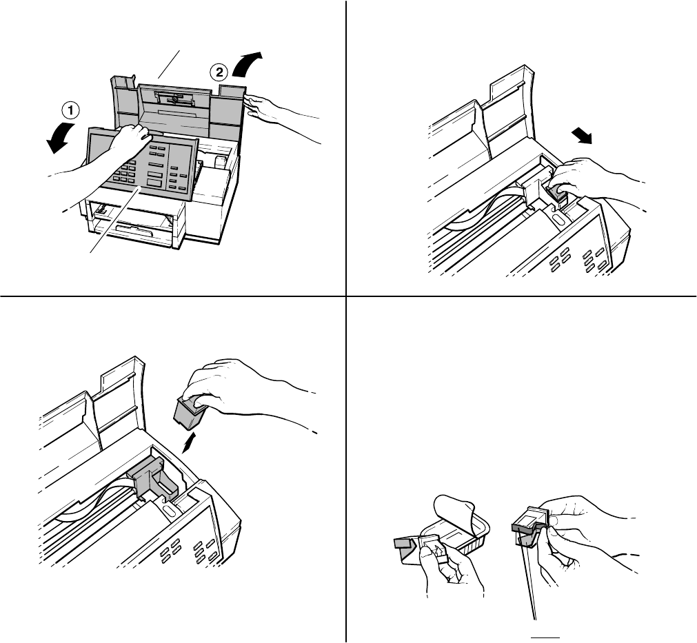
3-2 Routine Maintenance
Introduction
Use the guidelines in this chapter to keep the HP OfficeJet in the best operating condition.
Changing a Print Cartridge
When installing or replacing a print cartridge, following these recommendations will optimize the performance and
extend the lifetime of the ink cartridge.
DKeep print cartridges in the print cradle in the machine to reduce exposure to air
DKeep new unused cartridges in their sealed packaging until ready to use
DDo not turn the machine OFF before printing is complete
1Open the control panel, then the top cover. 2Pull the print cartridge toward you until it
releases and snaps forward.
Top cover
Control panel
3Lift the print cartridge out of its cradle. 4Open the new print cartridge box and container,
then grasp the print cartridge by the green top
and remove the cartridge from the container.
Gently remove both pieces of tape – blue and
white – covering the ink nozzles and vent hole.
CAUTIONS: 1) If you don’t remove the white
tape, the ink in the cartridge will be depleted
prematurely.
2) Do not to touch the ink nozzles or the copper
contacts. Fingerprints may damage them.
Remove both pieces of tape!
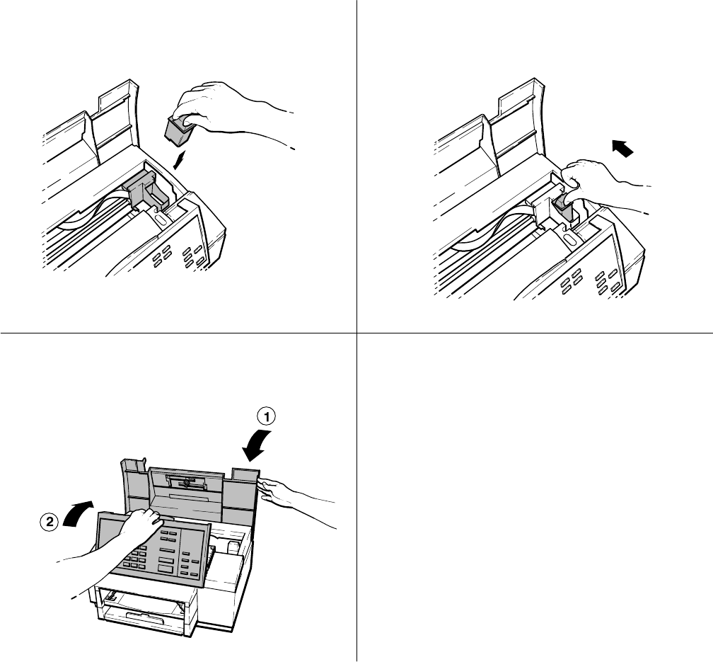
3-3
Routine Maintenance
5Place the print cartridge down into the cradle as
shown. Align the green arrow on the cartridge
top with the green dot on top of the cradle.
6Push the green arrow toward the green dot until
the cartridge snaps into place.
7Close the top cover, then close the control panel. Helpful Hint:
Be sure to close the control panel firmly, until
both corners snaps into place.
Exterior Cleaning
Follow the these recommendations when cleaning the exterior surfaces of the HP OfficeJet:
DUse a soft cloth moistened with water to wipe dust off the exterior
DDo not clean the interior of the machine
DKeep liquids out of the interior of the unit
3-4 Routine Maintenance
Notes:

4-1
Calibration and Adjustment
4
Calibration and Adjustment
Subject Page
Introduction 4-2. . . . . . . . . . . . . . . . . . . . . . . . . . . . . . . . . . . . . . . . . . . . . . . . . . . . . . . . . . . . . . . . . . . . . . . . . . . .
Print Calib Chart 4-2. . . . . . . . . . . . . . . . . . . . . . . . . . . . . . . . . . . . . . . . . . . . . . . . . . . . . . . . . . . . . . . . . . . . . . . .
4-2 Calibration and Adjustment
Introduction
The only procedure available outside of the factory environment is the calibration chart, which can be printed out and
used to determine if the top margin must be adjusted. This procedure is used to adjust the top margin when performing
a copy function. It is performed at the factory before shipment and should never need readjusting.
Print Calib Chart
WARNING: This procedure should only be accomplished under the direction of a trained HP support agent.
Do NOT perform this procedure unless directed to do so by the agent.
The distance between the page detect sensor and the location of the scanner will vary between machines due to parts
tolerances. This variation affects the top scanning margin. The scanner position calibration will adjust the top margin.
A Calibration Chart is used for this procedure and contains the following features:
DA check to see if the calibration is successful or needed
DInstructions on how to perform the calibration
DCalibration scale used to select the correct parameter value
To check if a calibration is needed, first print the Calibration Chart. Then cut the top of the chart along the dotted line.
Set the HP OfficeJet copy reduction setting to 100%. Make one copy of the chart by feeding the top end first into the
document feeder. If the hour-glass printed on the chart is either completely visible or not visible at all, a calibration is
needed. Ideally, exactly one-half of the hour-glass will be visible. Detailed instructions are provided in the following
paragraphs. A sample chart is provided following this procedure.
To print a calibration chart, you must enter the Service and Factory Menu. There are two methods that can be used to
access the Service and Factory Menu:
1. Press the “*” and “7” buttons simultaneously while powering on the HP OfficeJet.
2. From the “Enter Header Number” display, first use the “Backspace” button to erase the currently displayed
header number (if present), then press the “Redial/Pause”, “*”, “Redial/Pause”, “2”, “3”, “2” and “Enter/Save”
buttons in sequence. Press the menu button and scroll to the Service and Factory Menu.
Once the Service and Factory Menu has been accessed, it will remain part of the main menu structure until the HP
OfficeJet is powered OFF. Cycling the power OFF and then ON will remove the Service and Factory Menu from the
display and return to the regular user menu.
The same method used to navigate and select user menu functions is also used for the Service and Factory Menu. A
full description of the Service and Factory Menu is provided in chapter 5 of this manual.
4-3
Calibration and Adjustment
After accessing the Service and Factory Menu, scroll to the Print Calib Chart submenu and start printing the chart.
The chart contains a complete description of the following procedure:
1. Remove the top portion of the chart by cutting along the dotted line.
2. Enter the Change Stored Parameter submenu and select parameter 200.
3. Write down the existing value at parameter 200, then enter a new value of 1500.
4. Press the front panel Resolution button until FINE is displayed on the front panel display.
5. Using the front panel menu, set the Copy Reduction to 100%.
6. Load the chart (with the top portion removed at the dotted line) into the automatic document feed tray and make one
copy. Make sure the chart is loaded top end first with the print side facing down.
7. Look at the copy and find the top most visible tick mark of the Calibration Value Scale where the scale is cut off.
8. Determine the Calibration Value corresponding to this tick mark by reading the “How to Read Scale” portion of the
sample chart following this procedure. The normal range is 550 to 650 on the scale.
9. Reenter the Service and Factory Menu.
10. Scroll to the Change Stored Parameter submenu and access parameter 200.
11. Enter the Calibration Value determined from the “How to Read Scale” into parameter location 200.
12. The calibration test is complete. Check that the calibration is correct by making another copy of the chart
previously used (with the top portion removed). Ideally, one-half of the hour-glass will be visible.
A sample calibration chart is provided on the next page. Refer to it facilitate performing the procedure and to obtain
the calibration value.
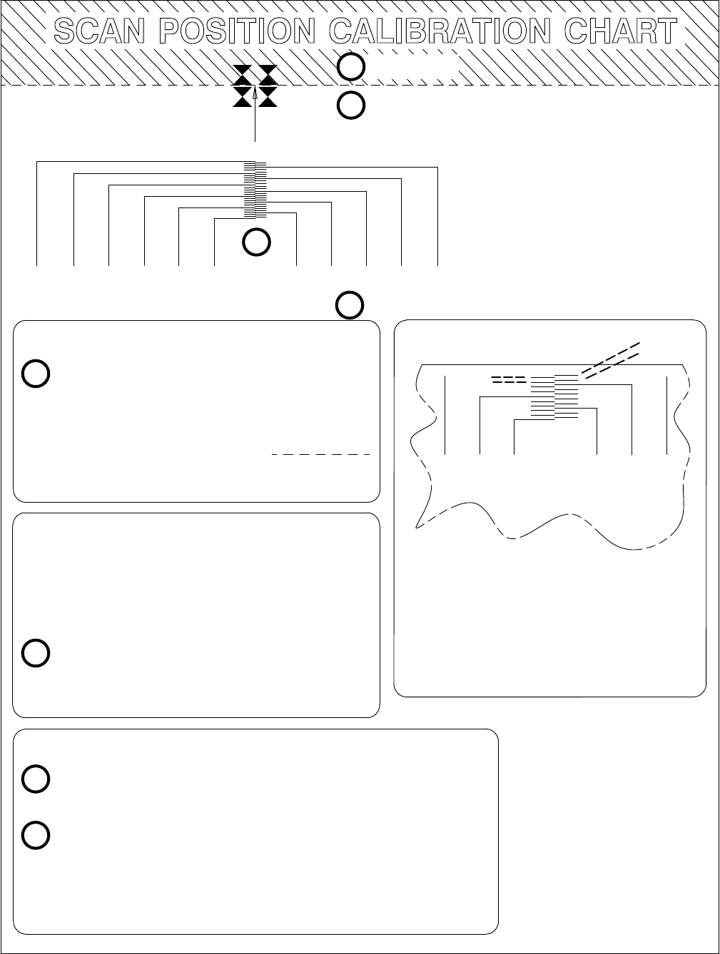
4-4 Calibration and Adjustment
CUT HERE
1
2
3
4
5
6
7
1
4
5
6
FEED THIS END FIRST TOPTOP
CALIBRATION VALUE SCALE
950 850 750 650 550 450 500 600 700 800 900
SET-UP
Cut the top of this chart along the
dashed line.
Enter the “Change Parameter” menu and
select parameter 200.
a) note existing value:
b) enter new value: 1500
MEASUREMENT
Exit the Service Menu and
a) set Copy Reduction to: 100%
b) set Resolution to: FINE
Load this sheet (after the top portion
is removed) into the FAX document
feed tray (print side down, top end
first). Make one copy.
CALIBRATION
Look at the copy and find the top most tick mark
of the Calibration Value Scale which is visible.
Determine the Calibration Value corresponding to this
tick mark. See “How to Read the Scale”.
Enter this value at parameter 200 location using the
“Change Parameter” menu. Calibration is complete.
How to Read the Scale
Moving from the left side to the right
side, the scale increments by 10 for
each scale tick mark (20 between
tick marks on the same side). The
highest readable value in this
example is 640.
CALIBRATION VALUE SCALE
500 600 700450550650
630
610
590
570
530
510
490
470
580
560
540
520
680
660
640
620
640
620
630
610

5-1
Problem Resolution
5
Problem Resolution
Subject Page
Introduction 5-2. . . . . . . . . . . . . . . . . . . . . . . . . . . . . . . . . . . . . . . . . . . . . . . . . . . . . . . . . . . . . . . . . . . . . . . . . . . .
Multi-Function Task Chart 5-2. . . . . . . . . . . . . . . . . . . . . . . . . . . . . . . . . . . . . . . . . . . . . . . . . . . . . . . . . . . . . . . . .
Problem Solving Process 5-2. . . . . . . . . . . . . . . . . . . . . . . . . . . . . . . . . . . . . . . . . . . . . . . . . . . . . . . . . . . . . . . . . .
Typical Questions and Answers 5-3. . . . . . . . . . . . . . . . . . . . . . . . . . . . . . . . . . . . . . . . . . . . . . . . . . . . . . . . . . . . .
Error Notification: Beeps, Blinking Lights and Messages 5-6. . . . . . . . . . . . . . . . . . . . . . . . . . . . . . . . . . . . . . . .
Display Messages: What they mean and what to do 5-7. . . . . . . . . . . . . . . . . . . . . . . . . . . . . . . . . . . . . . . . . . . . .
Solving Problems While Printing, Faxing or Copying 5-16. . . . . . . . . . . . . . . . . . . . . . . . . . . . . . . . . . . . . . . . . . .
Diagnostic Codes: What they are, how to read them and what to do 5-22. . . . . . . . . . . . . . . . . . . . . . . . . . . . . . . .
Fax Session Protocol: Diagnostic Code appearances in a communication 5-22. . . . . . . . . . . . . . . . . . . . . . . . .
Diagnostic Code Descriptions 5-25. . . . . . . . . . . . . . . . . . . . . . . . . . . . . . . . . . . . . . . . . . . . . . . . . . . . . . . . . . .
Communication Error Codes (level 400 and 500) 5-27. . . . . . . . . . . . . . . . . . . . . . . . . . . . . . . . . . . . . . . . . . . .
Power-On Initialization Tests 5-34. . . . . . . . . . . . . . . . . . . . . . . . . . . . . . . . . . . . . . . . . . . . . . . . . . . . . . . . . . . . . . .
Special Menus and Functions 5-35. . . . . . . . . . . . . . . . . . . . . . . . . . . . . . . . . . . . . . . . . . . . . . . . . . . . . . . . . . . . . .
Service and Factory Menu 5-36. . . . . . . . . . . . . . . . . . . . . . . . . . . . . . . . . . . . . . . . . . . . . . . . . . . . . . . . . . . . . . . . .
Service and Factory Menu Structure 5-36. . . . . . . . . . . . . . . . . . . . . . . . . . . . . . . . . . . . . . . . . . . . . . . . . . . . . .
System Error Codes 5-41. . . . . . . . . . . . . . . . . . . . . . . . . . . . . . . . . . . . . . . . . . . . . . . . . . . . . . . . . . . . . . . . . . . . . .
User-Menu Associated Parameter Structure 5-42. . . . . . . . . . . . . . . . . . . . . . . . . . . . . . . . . . . . . . . . . . . . . . . . . . .
Officejet Parameter Descriptions 5-43. . . . . . . . . . . . . . . . . . . . . . . . . . . . . . . . . . . . . . . . . . . . . . . . . . . . . . . . . . . .
LIU Identification 5-43. . . . . . . . . . . . . . . . . . . . . . . . . . . . . . . . . . . . . . . . . . . . . . . . . . . . . . . . . . . . . . . . . . . .
Ring Detection and Auto Answering 5-44. . . . . . . . . . . . . . . . . . . . . . . . . . . . . . . . . . . . . . . . . . . . . . . . . . . . .
Eavesdrop Detection and Automatic Answering 5-47. . . . . . . . . . . . . . . . . . . . . . . . . . . . . . . . . . . . . . . . . . . .
Connection Establishment 5-50. . . . . . . . . . . . . . . . . . . . . . . . . . . . . . . . . . . . . . . . . . . . . . . . . . . . . . . . . . . . . .
Pause Control 5-53. . . . . . . . . . . . . . . . . . . . . . . . . . . . . . . . . . . . . . . . . . . . . . . . . . . . . . . . . . . . . . . . . . . . . . .
Dial Tone Detection 5-54. . . . . . . . . . . . . . . . . . . . . . . . . . . . . . . . . . . . . . . . . . . . . . . . . . . . . . . . . . . . . . . . . . .
Dialing 5-60. . . . . . . . . . . . . . . . . . . . . . . . . . . . . . . . . . . . . . . . . . . . . . . . . . . . . . . . . . . . . . . . . . . . . . . . . . . . .
Call Progress 5-62. . . . . . . . . . . . . . . . . . . . . . . . . . . . . . . . . . . . . . . . . . . . . . . . . . . . . . . . . . . . . . . . . . . . . . . .
Modem Configuration 5-65. . . . . . . . . . . . . . . . . . . . . . . . . . . . . . . . . . . . . . . . . . . . . . . . . . . . . . . . . . . . . . . . .
Fax Session Configuration 5-67. . . . . . . . . . . . . . . . . . . . . . . . . . . . . . . . . . . . . . . . . . . . . . . . . . . . . . . . . . . . .
Redialing 5-68. . . . . . . . . . . . . . . . . . . . . . . . . . . . . . . . . . . . . . . . . . . . . . . . . . . . . . . . . . . . . . . . . . . . . . . . . . .
Miscellaneous 5-70. . . . . . . . . . . . . . . . . . . . . . . . . . . . . . . . . . . . . . . . . . . . . . . . . . . . . . . . . . . . . . . . . . . . . . .
5-2 Problem Resolution
Introduction
This chapter contains information which can be used to resolve problems encountered while using the HP OfficeJet.
Problems that require removing the top cover in order to troubleshoot or repair the machine must be referred to
qualified service personnel. Follow the instructions in this chapter to make certain the problem is in the machine and
not the result of an interface connection problem or a malfunction in the computer or software.
Multi-Function Task Chart
Use the Simultaneous Task Capability chart in Chapter 1 of this guide as a reference for which tasks can be performed
simultaneously. Attempting to perform concurrent tasks not supported may result in a display message or error
condition.
Problem Solving Process
1. Review the Troubleshooting chapter in the HP OfficeJet (LX) User’s Guide. Most problems are fairly simple to
resolve. The recommended way to solve them is to identify the problem and take the corrective steps provided.
2. A list of user available support resources is provided in Chapter 6. Use the resources list before calling the
Customer Support Center. The resources available can expedite problem resolution and get many users back in
operation without a service call. Some of the resources offer instant fax return of the support information requested.
3. Gather some basic information before calling for help. To facilitate prompt service, be sure to have the following
information readily available before contacting the HP Customer Support Center (CSC):
DProduct name and serial number
DDescription of the problem
DPurchase date and proof of purchase
DA valid credit card or purchase order number (required for HP’s Express Exchange option)
Call HP CSC: (208) 323-2551 Monday, Tuesday, Thursday, and Friday from 7:00 am to 6:00 pm (MST); Wednesday
from 7:00 am to 4:00 pm (MST).
An HP CSC agent will guide you through the following process to quickly determine and solve any problems you may
have:
DSetup and Operation Problems: First, the HP CSC agent will help solve any problems or answer any
questions relating to setup or operation.
DRemote Diagnostics: If setup or operation is not the problem, the HP CSC agent can attempt to identify
the problem using the remote diagnostics feature of your HP OfficeJet. This powerful capability provides
access to all user setup and machine operating parameters, and allows some problems to be detected and
corrected over the telephone line.
DArranging Repair: If the problem can not be resolved over the phone, the HP CSC agent will arrange to
replace or repair the unit using the HP Express Exchange or Standard Return program through the
Corvallis Service Center.
5-3
Problem Resolution
Typical Questions and Answers
The following series of questions are those typically asked by customers who need to know something about a
particular function or capability and which operations can be performed simultaneously.
Q: How fast does the HP OfficeJet print?
A: The HP OfficeJet can print up to 3 pages a minute. Draft and Letter print quality can be set using the front panel.
Also, various quality levels can be set through the printer drivers supplied with the unit. Draft quality print speed is 3
pages per minute and Letter quality print speed is 2 pages per minute.
Q: How fast does the HP OfficeJet send faxes?
A: The HP OfficeJet can send fax transmissions at up to 10 seconds per page. This speed is based on the standard
resolution with Error Correction Mode of the CCITT test chart #1. The speed of fax transmission through the wires is
dependent on the phone line, the receiving fax machine, the print density on the page(s) and the resolution setting.
Q: What is the page capacity of the fax document feed tray?
A: Using 20 lb. paper, the fax document feed tray will handle up to 20 pages. This tray assembly is commonly known
as the automatic document feed (ADF) assembly. Heavier weight paper restricts the number of sheets that the ADF
can handle and feed. If more than 20 sheets need to be sent, the additional sheets can be put on the ADF as the others
are processed through.
Q: What is the sheet capacity of the paper supply tray?
A: The front loading paper supply tray holds up to 100 sheets of plain paper. Letter, legal and A4 sizes can be used.
Q: Can I print a file from the PC and send a fax at the same time?
A: Yes. Load the fax document into the ADF and send. The PC print job will continue.
Q: Can I print a file from the PC and make copies at the same time?
A: No. The printer is busy with the print job and can”t simultaneously process copies through the print mechanism.
Q: What happens when the machine runs out of ink while printing an incoming fax?
A: The HP Officejet detects when the ink cartridge is empty. The incoming fax will be stored in memory until the
cartridge is replaced and then printed out. Based upon CCITT test chart #1, up to 24 pages can be stored in memory.
Q: What happens if I’m printing and someone tries to send me a fax?
A: The HP OfficeJet comes with 400kB of memory for fax/copy. When a fax is received during a print job, the fax is
stored in memory and printed after the print job is completed. Up to 24 pages can be stored in the memory. If a fax
exceeding the memory space is received, the fax will take precedence over the print job.
Q: What happens if the memory is filled with incoming faxes and someone tries to send me a fax?
A: Once the memory is filled, the HP OfficeJet will no longer answer and the sending party will get a busy or no
answer signal. The fax will not be sent and thus not lost. A front panel display will notify the user that fax reception is
disabled. As the faxes stored in memory are printed out, freeing up memory space, the HP OfficeJet will automatically
begin to answer fax calls again.
Q: Does the HP OfficeJet offer remote diagnostics?
A: Yes. This feature allows the HP OfficeJet support line to identify some problems over the phone lines and access
user setup settings and machine parameters.
5-4 Problem Resolution
Q: I have only one shared line for fax and voice calls. If I pick up an extension phone and realize that the call is a
fax call and not a voice call, can I still receive the fax?
A: The HP OfficeJet can share a phone line with voice calls in the Fax/TAM receive mode. TAM is an acronym for
telephone answering machine. When the HP OfficeJet is set in the Fax/TAM receive mode, and an answering machine
is used, the HP OfficeJet monitors the calls and responds to incoming fax tones on the line. So, if the phone is picked
up and you realize the call is a fax call, wait until you hear the fax tone, then hang up and the fax will be received.
Q: Which printer drivers can I use and which are supplied with the HP OfficeJet?
A: The HP OfficeJet is designed for the PC environment. Microsoftr Windows and top-tier DOS software drivers are
supplied. The HP Officejet is supported on a wide range of DOS applications using the HP DeskJet 500 series printer
drivers. Six internal fonts for DOS applications reside in the HP Officejet. No font cartridge capability is provided.
Q: Are separate ink cartridges needed for the printer and fax?
A: No. One print cartridge is used to print, fax and copy.
Q: What is broadcasting and does the HP OfficeJet offer it?
A: Broadcasting is the ability to send a fax document to more than one station at the same time. This feature is also
referred to as group dialing. The HP OfficeJet offers group dialing and can be set to speed dial groups of numbers
previously stored in memory. You can also send to several fax numbers (up to 10) by pressing the Enter/Save button
instead of the Start/Copy button after entering a phone number. The display will prompt you for additional numbers.
Q: What is polling and does the HP OfficeJet offer it?
A: Polling is the ability to allow fax machines to communicate requests for faxes from each other. The calling machine
requests, via fax tones, that a document stored in the other machine’s ADF or memory be transmitted to it. Both
machines must be set up to use this feature or no polling can occur. The HP OfficeJet can be set up to poll or be polled.
Polling is restricted to one station at a time, no group polling is offered.
Q: Does the HP OfficeJet offer delayed sending of faxes to take advantage of lower phone rates or different
time zones?
A: Yes. The HP OfficeJet can be set to send a fax up to 24 hours later. The fax can be either stored in memory or placed
on the ADF until the requested sending time.
Q: How much memory is included for printing and faxing?
A: A total of 1 MB of memory resides in the HP Officejet. Approximately 400 kB of memory is used for the fax/copy
features, providing for about 24 pages of fax data storage. Approximately 584 kB of memory is needed for system
operation while about 16 kB is used for PC print job storage. If using memory storage functions such as broadcasting
and delayed sending, 32kB of memory is reserved for incoming faxes.
Q: Can I send a fax from memory to another fax machine’s memory?
A: Yes, providing the other fax machine has the capability and capacity to store the incoming message in memory.
Q: Can I receive a fax into memory from another fax machine’s memory?
A: Yes, providing the HP OfficeJet is set for backup reception (factory default) and sufficient memory is available.
Based upon CCITT test chart #1, up to 24 pages can be stored in memory.
Q: Does Eclipse FAX SE have to be running to receive PC faxes?
A: No, but the HP OfficeJet LX Manager does. You need to run the PC fax software package to view the fax.

5-5
Problem Resolution
Q: What is the print resolution offered in the fax, printing and copy modes?
A; Refer to the following table.
Mode Resolution
Printing from PC with Windows 3.1 driver 600 dpi x 300 dpi with REt
Printing from PC with DOS (text) 600 dpi x 300 dpi
Printing from PC with DOS (graphics) 300 dpi x 300 dpi
Fax printing 200 dpi receive scaled to 300 dpi
Fax sending (Standard) 100 dpi x 200 dpi (approximate)
Fax sending (Fine) 200 dpi x 200 dpi (approximate)
Fax sending (Photo) 200 dpi x 200 dpi (approximate) with 32 levels of
greyscale
Copy 200 dpi x 200 dpi (approximate) with Fine resolution
as default, can also use Photo mode
dpi = dots per inch; dots per 25,4 cm. REt = resolution enhancement technology
Q: What level of greyscale is provided for photo images?
A: The HP OfficeJet provides 256 levels of greyscale for printed documents through the printer drivers on Windows
and other applications for printing photographic images from the PC. 32 levels of grayscale are provided for faxing
and copying photographic images.
Q: Is the print quality similar for printing and faxing?
A: Print quality of documents sent from the PC applications with the Windows driver are the highest quality at 600 dpi
x 300 dpi with resolution enhancement to smooth the edges. In fax mode, the print quality is dependent on the
scanning resolution of the sending fax machine as well as the HP OfficeJet. The sending fax machine most likely
sends the fax at 100 dpi x 200 dpi or 200 dpi x 200 dpi. The HP OfficeJet receives faxes and then scales them to 300 dpi
for printing. In copy mode, the internal 200 dpi scanner scans the document and the data is scaled to 300 dpi for
printing.
Q: What fonts are supported?
A: There are six internal fonts in the HP OfficeJet to support DOS applications. When using the Windows driver, all of
the TrueType fonts are supported. An additional 14 TrueType fonts are shipped with the Windows 3.1 driver.
Although the HP OfficeJet is fully compatible with the HP DeskJet 520, it does not support font cartridges nor
downloadable soft fonts.
Q: What happens when a fax document larger than Letter size is received by the HP OfficeJet?
A: With automatic reduction set to ON, the HP OfficeJet automatically reduces the image to fit the paper size loaded
in the supply tray. The fax and copy functions support Letter, Legal and A4 paper sizes. Also, the paper size should
match the size set in the front panel menu.
Q: How long does it take to copy a document?
A: Copy speed is approximately 50 seconds per page for a typically dense letter-sized page of text. Dense text and
graphics will take longer. Copying in Photo mode resolution also takes longer.
Q: Can the copier reduce the copies made?
A: Yes. The copy feature includes the ability to reduce images from 100% down to 70% in 5% increments.

5-6 Problem Resolution
Error Notification: Beeps, Blinking Lights and Messages
Certain error conditions can be incurred when a wrong button is pressed, a process is cancelled or an internal machine
problem is detected. The HP OfficeJet will notify the user when one of these conditions occurs. The error notification
can be in the form of beeps, blinking lights or messages in the display. Refer to the following table for conditions and
typical methods of notification.
Type of notification: Error condition:
Three short beeps.
An unavailable function was requested.
A button for a function that wasn’t available at
that time was pressed.
(Example: You can’t use the Menu button while
sending a fax.)
Nine short beeps. See Display light blinks on
and off. An error message is displayed that
describes the problem and tells you how to
solve it, if applicable.
An error interrupted an activity in progress.
An error occurred which has interrupted or
cancelled the current activity.
(Example: lifting the top of the control panel while
sending a fax causes the fax to be cancelled.)
You may need to take some action to clear the
error before continuing to use the HP OfficeJet.
Look up the displayed message in the next
section of this chapter for more information.
Nine short beeps. See Display light blinks on
and off. A “SYSTEM ERROR” message is
displayed along with a three-digit code.
(Refer to the Displayed Messages” section later
in this chapter.) Record this code before calling
for service.
An internal problem was detected.
A problem with the internal mechanical or
electronic components has been detected.
Service is required.
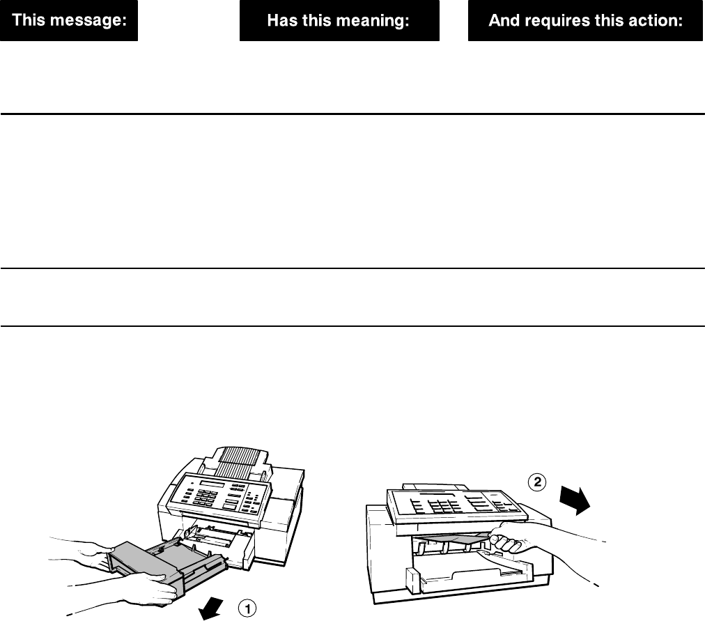
5-7
Problem Resolution
Display Messages: What they mean and what to do
Different error or operating conditions will cause the HP OfficeJet to notify the user when such conditions occur. The
messages will appear in the display. Refer to the following table for conditions, typical messages and recommended
corrective action.
The control panel display messages in the following table are presented in alphabetical order for easy reference.
Display Messages
nn pages sent
Poor Quality
The fax you just sent may contain
poor print quality resulting from
problems with the phone line.
Contact the receiver and verify
quality or resend the fax.
Add paper
then press START
You are printing and the paper tray
is empty. Load paper for your print job, then
press the Start/Copy button.
If paper is already loaded in the
paper tray when you get this
message, remove it. (Also check for
any partially-loaded sheets and
remove them, too.) Discard any
damaged or curled sheets from the
stack, then reload the stack and
press Start/Copy.
Cancel pending fax?
1=Yes 2=No
You pressed Stop while the HP
OfficeJet was waiting to redial and
send a memory-stored fax.
Press 1 to cancel the memory-
stored fax. Press 2 to continue
redialing the memory-stored fax.
Clear print jam
then press START
A piece of paper has jammed inside
the printer mechanism. Remove the output tray and pull out
all wrinkled or torn pieces of paper
from the paper path. Also remove
wrinkled or torn pieces of paper
from the paper tray. When finished,
replace the output tray and press
the Start/Copy button.
(Continued on next page)
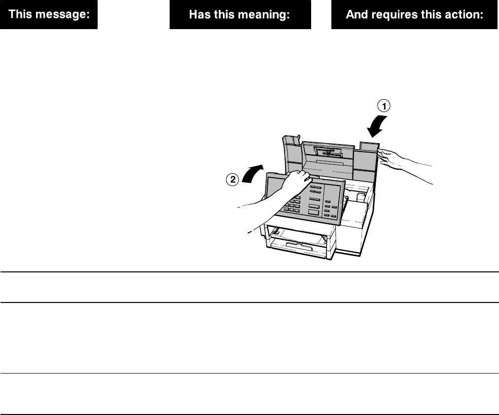
5-8 Problem Resolution
Display Messages (Continued)
Close cover
The control panel is open, the top
cover is open, or both the control
panel and the top cover are open.
First close the top cover, then press
down on the control panel until it
snaps into place. When both are
closed properly, the “Close cover”
message will go away.
Top cover
Control panel
Copy cancelled
You pressed the Stop button while
copying was in progress. No action is required.
Delayed fax
pending
You have already scheduled a
delayed fax. Only one delayed fax
can be scheduled at a time.
Wait until after the delayed fax has
been sent, then set up the next one.
If you want to cancel the first
delayed fax instead, select Send
Fax Later, then select Cancel
Send.
Delete this fax?
1=Yes 2=No
You pressed the Stop button while
a fax was being received or printed. Press 1 to stop receiving and delete
the fax, or press 2 to continue
receiving and printing the fax.
Fax cancelled
(
fax number)
The bottom line displays the fax
number you were sending to or
receiving from when the fax was
cancelled. The fax could have been
cancelled because of one of the
following:
1) You pressed the Stop button.
2) You lifted the control panel.
3) You removed the document while
it was being scanned.
4) The document jammed while it
was being scanned.
If you intentionally cancelled the
fax, no action is required. If not, you
should resend the entire document.
Note: It’s possible that part of your
document was successfully
transmitted, but if you are not able
to check with the person you were
sending to, we recommend
resending the entire document.
(Continued on next page)

5-9
Problem Resolution
Display Messages (Continued)
Fax failed from
(
fax number)
A communication error between
your HP OfficeJet and the sending
fax machine resulted in a failed
transmission. The fax number of the
sending fax machine is displayed on
the bottom line.
Check for dial tone. You may want
to contact the person who tried to
send the document and ask them to
resend it. Failed transmissions are
most often caused by noise on the
telephone line.
Fax failed from
(unknown)
A communication error between
your HP OfficeJet and the sending
fax machine resulted in a failed
transmission. The fax number of the
sending fax machine is unknown.
Check for dial tone. You may want
to contact the person who tried to
send the document and ask them to
resend it. Failed transmissions are
most often caused by noise on the
telephone line.
Fax in memory
One or more incoming faxes were
stored in memory while the HP
OfficeJet was either out of paper,
out of ink, or the wrong size paper
for fax reception was loaded. This
message is displayed alternately
with the error message telling you
what needs to be corrected.
Read the message that alternates
with this one (e.g., “Out of paper for
fax/copy”). Correct the indicated
problem.
Fax in memory
Memory full
One or more incoming faxes were
stored in memory and filled the
memory to capacity while the HP
OfficeJet was either out of paper,
out of ink, or the wrong size paper
for fax reception was loaded. This
message is displayed alternately
with the error message telling you
what needs to be corrected.
Read the message that alternates
with this one (e.g., “Out of ink,
Replace pen”). Correct the
indicated problem.
The HP OfficeJet cannot receive
any more faxes until you correct the
problem and the memory-stored
faxes are printed.
Fax in memory
press START
A fax was stored in memory while
the HP OfficeJet was not ready to
print (out of paper, out of ink, wrong
size paper loaded, or printer busy),
but the problem has now been
corrected.
Press the Start/Copy button to
print the fax stored in memory.
Fax poll failed
The HP OfficeJet tried to poll
another fax machine. The poll failed
because either there was no
answer, the line was busy, or the
other fax machine was not ready to
be polled.
Check with the sender to make sure
their machine is ready to be polled
and to verify the fax number. Then
set up to poll again.
Fax printing
disabled
The HP OfficeJet is out of ink.
Incoming faxes will be received to
memory until the print cartridge is
replaced.
Replace the print cartridge.
(Continued on next page)

5-10 Problem Resolution
Display Messages (Continued)
Fax reception
disabled
The HP OfficeJet is unable to
receive faxes due to one of the
following error conditions: the print
cartridge is out of ink or not
installed, paper has jammed during
printing, you’re out of paper, the
wrong size paper is loaded for fax
reception, or the memory is full.
Read the message that alternates
with this one, then correct the
error it describes.
Fax send failed
No dial tone
You tried to send a fax, but your
telephone line is not operational. Check your telephone line
connections to the wall jack and to
the HP OfficeJet. Try again.
Fax send failed
No document
This message is displayed when
there’s an error with a fax you
scheduled using the Send Fax Later
feature. It indicates that there was
no document in the fax loading tray
at the time you scheduled a fax to
be sent.
Send your fax as desired: either
reschedule the fax using the Send
Fax Later feature, or send the fax
manually.
Fax send failed
Try again
You tried to send a fax, but some
kind of communication error
occurred before the fax data could
be transmitted.
Try sending your fax again.
The fax machine you’re sending to
may not be ready to receive faxes.
Try contacting someone at the
receiving location.
Fax to each
number separately
The HP OfficeJet tried to store a
document in memory before
sending it to a group of fax
numbers. There was not enough
memory to store the document.
You must send the fax to each fax
number separately.
Load document
before Start Time
You scheduled a fax using the Send
Fax Later feature and chose to
send it directly from the fax loading
tray.
Load the document in the fax
loading tray before the scheduled
start time. In the mean time, you
can send faxes as you normally
would.
Memory full
Press START
You are in the middle of making
multiple copies of a document and
the memory is full.
Press the Start/Copy button. The
HP OfficeJet will make a single
copy of your document.
Memory full
Press STOP
The HP OfficeJet tried to store a
document into memory before
faxing it to multiple locations or at a
future fax time. Either there is a
received fax in memory waiting for
an error condition to be corrected
before it can be printed, or this
document is too large to fit into the
memory of the HP OfficeJet.
Press the Stop button. If there is an
error condition to correct, it will be
displayed. If no error message is
displayed, you can assume that this
document is too large to fit into
memory and you will need to send it
to one location at a time.
(Continued on next page)
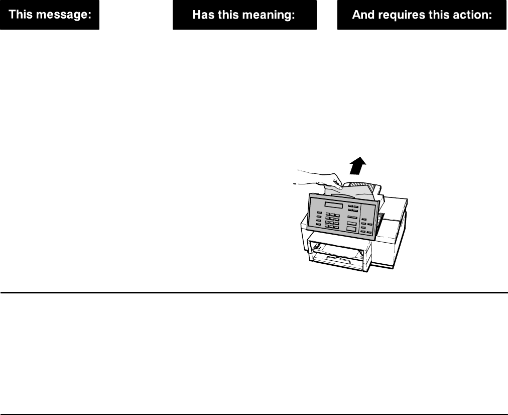
5-11
Problem Resolution
Display Messages (Continued)
Open cover
Clear copy jam
The document you loaded for
copying was either loaded
improperly or jammed while
being scanned.
If the document is
not
jammed,
remove it and reload it.
If the document is jammed, open
the top of the control panel (pull the
top ledge toward you) and remove
the document. Close the control
panel by pressing it down firmly
until it snaps into place. Reload the
document.
Open cover
Clear fax jam
The document you loaded for faxing
was either loaded improperly or
jammed while being scanned.
If the document is
not
jammed,
remove it and reload it.
If the document is jammed, open
the top of the control panel (pull the
top ledge toward you) and remove
the document. (See the illustration
for the previous message.) Close
the control panel by pressing it
down firmly until it snaps into place.
Reload the document.
Open cover
Load pen
No print cartridge is loaded in the
HP OfficeJet. Load a print cartridge.
Note: If you get this message after
recently installing a print cartridge,
try removing it and reloading it.
Make sure you have removed both
pieces of tape from the print
cartridge.
(Continued on next page)

5-12 Problem Resolution
Display Messages (Continued)
Out of ink
Replace pen
The print cartridge in the HP
OfficeJet is out of ink.
If you have the Backup Reception
feature turned on in the menu (On
is the factory setting) your incoming
faxes will be stored in memory until
you replace the print cartridge. You
can continue to print from your PC
for awhile, but your print quality may
be reduced and you will get blank
pages eventually.
Replace the print cartridge as soon
as possible.
If the memory fills to capacity
before you replace the print
cartridge, the HP OfficeJet won’t be
able to receive faxes and the “Fax
reception disabled” message will be
displayed alternately with this
message.
Note: If you get this message
after recently installing a print
cartridge, try removing it and
reloading it. Make sure that you
have removed both pieces of tape
from the print cartridge.
Out of paper
for fax/copy
The HP OfficeJet has attempted to
print a received fax or make a copy
and one of these conditions exists:
1) The paper tray is empty.
2) The wrong paper size is loaded
for receiving faxes, making copies,
and printing reports from the menu.
3) The paper loaded in the paper
tray is buckled (not flat), so the HP
OfficeJet can’t pick it correctly.
If paper or envelopes are loaded,
remove them. Then load either
Letter-, A4-, or Legal-size paper into
the paper tray. Make sure the paper
lays flat in the paper tray.
Paper load failed
Press START
The HP OfficeJet has failed to pick
a piece of paper from the paper
tray.
Press the Start/Copy button. If
paper is picked correctly, the
message will not be displayed
again, and you can continue to use
the HP OfficeJet normally.
If the message reappears, try
removing the stack of paper from
the paper tray, straightening it, and
reloading.
Poll cancelled
You pressed Stop after setting up a
document to be polled. Your
to-be-polled setup has been
cancelled.
No action is required.
Press START to send
Group full
You have entered the limit, 10 fax
numbers, while sending to a group
of fax numbers (broadcasting).
Press the Start/Copy to begin
sending the fax to your group.
Printer busy
The printer is in the middle of
printing a file from your PC, so it is
temporarily unavailable for other
types of printing.
Wait for the print job to finish before
starting another operation that
requires printing (such as copying
or printing reports).
(Continued on next page)
5-13
Problem Resolution
Display Messages (Continued)
Printing. . .
(Date and Time)
The HP OfficeJet is printing a file
from your PC. No action is required. You may send
a fax while printing, if desired. Re-
ceived faxes will be stored in
memory, then printed when your
print job is complete.
Printing. . .
Waiting for data
The printer has paused to wait for
further print data. Usually, no action is required.
However, if you are waiting for the
last page
of your print job at the
time you see this message, press
Load/Eject to eject the last page.
Ready
Out of fax paper
Either there is no paper loaded in
the paper tray, or the wrong size pa-
per is loaded for printing received
faxes, making copies, or printing
reports from the menu.
If you want to be able to print
received faxes, make copies, or
print reports from the menu: Load
Letter-, A4-, or Legal-size paper into
the paper tray.
Redial pending
Try again later
You tried to send a fax from the fax
loading tray while a memory-stored
fax was waiting to redial (sending to
a group or sending a delayed fax).
Wait until the memory-stored fax
has been sent before sending a fax
from the fax loading tray.
Remove document
and reload
The HP OfficeJet was unable to
load the document you placed into
the fax loading tray.
Remove the document from the fax
loading tray, straighten the stack,
and reload it.
Removing document
A document is being ejected from
the fax loading tray after you
cancelled a fax or a copy, or after
the power was lost during scanning.
No action is required. If you don’t
want to wait while each page is
ejected, open the control panel and
remove the document yourself.
Then close the control panel.
Report cancelled
You pressed the Stop button while
a report was being printed. No action is required.
Report in memory
press START
The HP OfficeJet stored an
automatic report in memory while
the paper tray was empty.
Press Start/Copy to begin printing
the report.
Self test
(Please wait)
Each time the power is turned on,
the HP OfficeJet tests itself to make
sure it’s in good working order. If it
finds a problem, an error message
will be displayed.
Wait for a few seconds for this
message to clear before using the
HP OfficeJet.
If a “SYSTEM ERROR” message is
displayed that advises you to call for
service, record the 3-digit error
number before calling.
(Continued on next page)
5-14 Problem Resolution
Display Messages (Continued)
Store fax now?
1=Yes 2=No
While scheduling a fax, you are
prompted to decide whether to
1) store the document in memory
for sending later, or
2) place the document in the fax
loading tray until the designated
start time.
If you want to store the fax in
memory until the start time, press
1. If you don’t want to use up the
memory, or if you don’t think your
document will fit into memory, press
2 and place your document in the
fax loading tray before the start
time.
Stored data lost
Call for service
Settings that were stored are lost.
All settings are returned to the
factory defaults.
You can continue to use the HP
OfficeJet (LX) but the battery may
be discharged. You should call for
service at your convenience. Refer
to Chapter 6 of this guide.
Stored data lost
Check Settings
Settings that were stored are lost.
All settings are returned to the
factory defaults.
You can continue to use the HP
OfficeJet (LX) but the battery may
be discharged. You should call for
service at your convenience. Refer
to Chapter 6 of this guide.
Storing. . .
Memory used: xx%
You are storing a document in
memory to be faxed later, or to be
sent to a group of fax numbers. The
bottom line shows you how much of
the memory is being used to store
the document. There’s a total of
about 24 pages (400 KB) of
memory available for faxing and
copying.
Wait until the storing is complete to
make sure your document will fit
into the available memory. If your
document won’t fit in memory, a
message will tell you what to do
next.
SYSTEM ERROR
nnn
Call for service
An error has occurred that requires
servicing. Please record the error number,
then do one of the following:
If the error number begins with
“1”
: Turn off the power, then turn it
on again. If the error message is
gone, you may be able to continue
using the HP OfficeJet. But if the
error message remains, contact
HP’s Customer Support Center to
service your HP OfficeJet.* It
cannot be used until it is serviced.
If the error number begins with
“2”
: Contact HP’s Customer
Support Center to service your HP
OfficeJet.* There’s a problem with
the scanning device, so you won’t
be able to send faxes or make
copies reliably. However, you will be
able to receive faxes, print files from
your PC, and print reports until your
HP OfficeJet is serviced. Press
Stop to clear the error message.
(Continued on next page)

5-15
Problem Resolution
Display Messages (Continued)
If the error number begins with
“3”
: Contact HP’s Customer
Support Center to service your HP
OfficeJet.* There’s a problem with
the internal part that controls fax
transmissions, so you won’t be able
to send or receive faxes. However,
you will be able to make copies,
print files from your PC, and print
reports until your HP OfficeJet is
serviced. Press Stop to clear the
error message.
SYSTEM ERROR
nnn
Turn power off/on
An error has occurred that may
require servicing. In some cases
the error can be cleared by turning
off the power, then turning it on
again.
Turn the power off, then on again. If
the message is no longer displayed,
the problem has been solved and
you can continue using your HP
OfficeJet normally.
If the message is still displayed
after powering off and on, there’s an
internal problem that requires
servicing. Record the 3-digit error
number in the message, then
contact HP’s Customer Support
Center to service your HP Office-
Jet.
Turn power off
Clear print jam
A print jam has occurred. Turn off the power to the HP
OfficeJet. Remove the output tray
and pull out all wrinkled or torn
pieces of paper from the paper
path. Also remove wrinkled or torn
pieces of paper from the paper tray.
When finished, replace the output
tray and turn on the power.
If this message is displayed
frequently, contact HP’s Customer
Support Center for help.
CAUTION: Any faxes stored in
memory will be deleted when you
turn off the power.
Waiting for poll
You have set up a document to be
polled from the fax loading tray. No action is required. If you need to
send a fax or make a copy, you can
remove the document temporarily,
then replace it when you are done.
Waiting to dial
(fax number)
The HP OfficeJet has tried to dial
the displayed fax number, but the
phone line is already in use. It could
be in use by a received fax,
because the phone is ringing, or
because your phone is off-hook.
No action is required. The HP
OfficeJet will wait until the phone
line is free, then dial the fax
number.
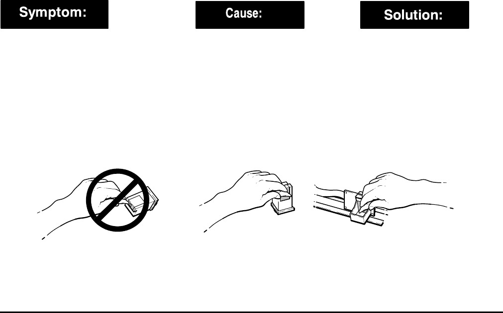
5-16 Problem Resolution
Solving Problems While Printing, Faxing or Copying
Use the following table of symptoms, causes and solutions to help resolve problems that may be experienced while
printing, faxing or copying.
Solving Printing/Faxing/Copying Problems
Lines or dots are missing from
the characters in the printout.
The connection between the print
cartridge and cradle is intermittent.
OR
Remove the print cartridge and
reinstall it. Try printing again. You
may need to repeat this before the
ink resumes a continuous flow.
OR
The copper contacts of the print
cartridge are dirty. 1. Remove the print cartridge. Use
a lint-free damp cloth to gently
clean the copper contacts on the
print cartridge and the print
cartridge cradle.
2. Reinstall the print cartridge and
try printing again. If the print quality
remains poor after cleaning the
contacts, clean the ink nozzles as
described for the next symptom in
this table.
The print cartridge has dried ink
on the nozzles.
The ink nozzles of the print
cartridge are clogged. 1. Press the Clean Pen button and
wait about 15 seconds while the ink
nozzles are cleaned automatically.
Then print the Self Test report.
Check the two print cartridge test
patterns in the Self Test report. If
the diagonal line has white gaps in
it, or if the area fill has horizontal
white lines in it, continue with step
2; otherwise, stop here and
continue printing normally.
(Continued on next page)
5-17
Problem Resolution
Solving Printing/Faxing/Copying Problems (Continued)
2. Remove the print cartridge. Hold
the print cartridge by the green top.
Use a stiff card or other rigid paper
to scrape the dried ink from the
nozzles. Then use a lint-free damp
cloth to gently clean the ink nozzles.
Reinstall the print cartridge and
print the Self Test report again.
Check for white gaps and white
lines. If you find some, continue
with step 3; otherwise, stop here
and continue printing normally.
3. Remove the print cartridge. Hold
the print cartridge by the green top.
Place two drops of clean water on
the gold rectangle of the print
cartridge for about 60 seconds,
then gently remove the water from
the print cartridge with a lint-free
damp cloth. Reinstall the print
cartridge and try printing again. You
may need to print a few pages
before the ink resumes a
continuous flow.
CAUTION: Do not clean the print
cartridge unnecessarily, because it
may shorten the life of the print
cartridge.
4. If the print quality remains poor
after trying steps 1 through 3, install
a new print cartridge.
The last page of the file wasn’t
printed.
The HP OfficeJet is waiting to see if
there is more data coming before
releasing the last page.
Press the Load/Eject button
or
wait
for a few minutes and your last
page will be released. If after five
minutes has passed and the HP
OfficeJet has not received any more
data, the last page of your file will
be printed.
(Continued on next page)
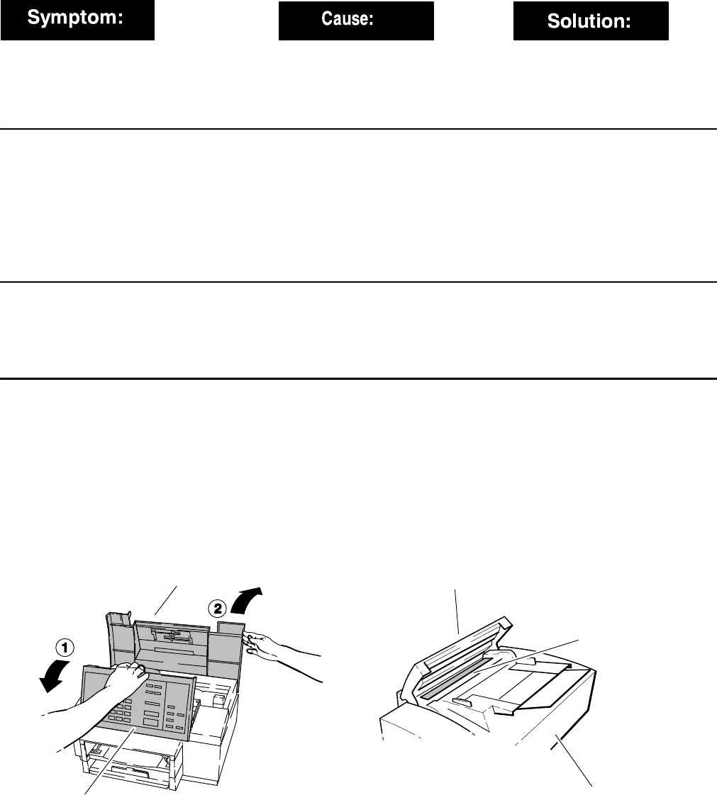
5-18 Problem Resolution
Solving Printing/Faxing/Copying Problems (Continued)
Parts of my documents are being
clipped when I print from my
Windows application.
The Windows driver for the HP
OfficeJet has a minimum top
margin of 0.33 in. (8.4 mm) and a
minimum bottom margin of 0.67 in.
(17 mm).
Before you print your document,
make sure the entire document is
visible in the “Print Preview” of your
Windows application.
I can’t get the font size I want
when printing from my DOS
application.
The HP OfficeJet does not support
the use of font cartridges. Some DOS application printer
drivers require that certain font
styles are resident on the printer.
The HP OfficeJet has various
internal fonts available but cannot
use additional fonts provided by HP
DeskJet font cartridges. You must
reformat your document using one
of the internal fonts in the HP
OfficeJet.
My phone call is cut off when I
try to make a copy.
If you are talking on a phone
attached directly to the HP Office-
Jet and you press the Start/Copy
button, the HP OfficeJet assumes
that you are sending a fax.
To resume your telephone
conversation, press the Stop
button.
Note: You cannot make copies while
talking on a phone attached directly
to the HP OfficeJet.
There are dark streaks or lines
on copies or on faxes sent from
the HP OfficeJet.
The scanner glass or reflective tape
may be dirty. Apply some glass cleaner to a soft,
lint-free cloth, then gently wipe the
scanner glass and tape clean.
To locate the scanner glass and
tape: Open the control panel by
pulling the top ledge toward you,
then open the top cover. Look in-
side the control panel for a glass
strip that’s about 3/4-inch (1.9 cm)
wide and 9 inches (23 cm) long.
The tape is opposite the glass.
Top cover
Control panel
Scanner glass
Control panel
Back of the HP OfficeJet
and reflective tape
(Continued on next page)

5-19
Problem Resolution
Solving Printing/Faxing/Copying Problems (Continued)
I can print, scan and change de-
vice settings with the HP Office-
Jet LX manager, but PC Fax
doesn’t work properly.
You may have a different CAS
installed. Only one CAS modem
can be used on a PC.
Remove (delete) the software for
the other CAS modem.
The HP OfficeJet LX never an-
swers a call.
Distinctive Ring is set to ON, but
you don’t have Distinctive Ring ser-
vice.
Refer to the user’s guide for instruc-
tions on how to turn OFF the Dis-
tinctive Ring feature.
Eclipse FAX SE doesn’t work on
the PC.
You may have previously installed a
CAS fax modem that was removed
before Eclipse FAX SE was
installed. Only one CAS modem
can be used on a PC.
Remove (delete) the software for
the other CAS modem.
Nothing happens when I try to
print.
If the HP OfficeJet LX printer
doesn’t respond when you try to
print, it may be set to the wrong
port.
Run the Windows control panel, se-
lect Printers, select the HP Office-
jet LX, then click the Connect but-
ton. Select the port that is con-
nected to your device. Do not select
HP OfficeJet LX. Click OK, close
Printers and the control panel, and
try printing again. If you still cannot
connect, close the HP OfficeJet LX
manager, exit Windows and turn the
machine OFF. Check the cable con-
nections, port selection and setup.
Turn the machine back ON. Restart
Windows and the HP OfficeJet LX
manager.
You get the message, “LPT1 is in
use.”
The HP OfficeJet LX cannot access
LPT1. If you are using a switch to run two
printers from a single LPT port, be
sure that all HP OfficeJet LX activi-
ties are complete, and the HP Offi-
ceJet LX manager and Eclipse FAX
SE are closed before switching to
another printer.
You get the message, “Printer
not responding.”
Your HP OfficeJet LX is turned OFF
or disconnected. Turn your HP OfficeJet ON. Make
sure the interface cable is con-
nected. Click Reconnect if your HP
OfficeJet LX was previously able to
connect to the device, check that
the cable is securely attached at
both ends,, the device is turned ON
and “Ready” is displayed on the
front panel. Check that any data
switch is set to connect to the HP
OfficeJet LX. Then click Recon-
nect.
(Continued on next page)

5-20 Problem Resolution
Solving Printing/Faxing/Copying Problems (Continued)
The date on the control panel
display is incorrect. The header
information and speed dial
numbers are missing.
The battery inside the HP OfficeJet
has failed, causing all of the menu
features to revert to their factory
settings.
Settings that contained alphabetic
and numeric characters you entered
(such as header name and number,
speed dial names and numbers,
etc.) have been erased.
You can continue to operate your
HP OfficeJet without the battery.
However, if you re-enter the menu
settings and then turn off the power,
the settings will be erased again.
Contact HP’s Customer Support
Center regarding battery
replacement.
Some of my menu settings seem
to have reverted to their factory
values without my changing
them.
An internal error has caused some
or all of the menu features to revert
to their factory settings.
Print the Self Test report and check
the Current Settings column to find
out which menu settings have re-
verted to the factory settings.
Change the settings and re-enter
data as
appropriate.
For instructions on how to print the
Self Test report, see “Self Test Re-
port” in Chapter 3.
I can’t receive a fax from my
extension phones.
You don’t have the Fax/TAM
receive mode setup. If you need to be able to receive
faxes from extension phones,
change the setup to Fax/TAM.
Incoming calls are not being an-
swered.
The Distinctive Ring feature may be
turned ON when the service is not
available in your area or you have
not yet subscribed to the service.
Turn OFF the Distinctive Ring fea-
ture and request the fax be sent
again.
Items on the HP OfficeJet LX
manager menu bar are grayed
and the “Device Not Connected”
error is displayed.
The HP OfficeJet LX is not properly
connected. If this happens after a first-time
installation:
Verify that the device is turned ON
and the cable is properly
connected.
Verify that the cable is good.
Verify that your LPT port allows
bi-directional communication.
If you have been using the HP
OfficeJet LX manager and this
happens:
Verify that the device is turned ON
with the message “Ready” dis-
played.
Verify that the cable is properly
connected at both ends.
If a data switch is used, verify that it
is set to HP OfficeJet LX.
Restart Windows and try again.
(Continued on next page)
5-21
Problem Resolution
Solving Printing/Faxing/Copying Problems (Continued)
The printer prints part of a can-
celled print job.
Once you start a print job, the docu-
ment is sent to the printer. If you
cancel the print job,while the printer
is out of paper or otherwise dis-
abled, the portion of the document
that was sent prints when the print-
er is available.
To prevent portions of cancelled
print jobs from printing, press Load/
Eject on the front panel while the
message “Printing/Waiting for
data...” is displayed.
PC faxes quit during sending.
It is possible that your PC is over-
loaded with activity like sending
more than one fax at a time, or
starting applications that take a long
time.
Try to reduce the activity on your
PC while faxes are being sent or re-
ceived.
Faxes routed to the PC are
printed instead.
If the HP OfficeJet LX manager is
not running, faxes are printed upon
receipt. If your PC is too busy, faxes
are printed on receipt.
The HP OfficeJet LX manager may
have lost the connection to the de-
vice. Open the front cover and
make sure that the HP OfficeJet LX
manager says “Close Cover.” If it
does not, check the cable connec-
tion to the device. If it appears OK,
close and restart the HP OfficeJet
LX manager.

5-22 Problem Resolution
Diagnostic Codes: What they are, how to read them and what to do
Diagnostic codes are 12- or 15- digit codes that can be used by a customer support representative to diagnose fax
transmission (send and receive) problems. The diagnostic codes appear on the Fax Log Report which the user can have
the HP OfficeJet print on demand or automatically after each fax transaction. Instructions for printing reports are
provided in Chapter 3 of the HP OfficeJet User’s Guide and in Chapter 3 of this document.
Use the sample Fax Log Report shown below to identify the diagnostic code. The paragraphs following the sample
will help to analyze the code and what problem may have affected the machine’s operation.
HP OfficeJet
Personal Printer/Fax/Copier Fax Log Report for
ACME Co.
619 555-1234
Oct-27-94 2:30PM
Identification Result Pages Type Date Time Duration Diagnostic
5553756 OK 03 Sent Oct-19 10:14A 00:02:05 001000000000
999 555 4783 Stop 02 Received Oct-19 01:21P 00:01:38 001000000000
5551900 No Answer 00 Poll-in Oct-20 09:57A 00:00:09 001000000000403
Public Images Inc. Busy 00 Sent Oct-20 11:48A 00:00:08 001000000000
5557990 Error 01 Poll-out Oct-20 04:38P 00:01:18 001000000000411
5557990 Jammed 03 Sent Oct-20 05:10P 00:02:40 001000000000
Henry No Document 00 Sent Oct-21 01:00A 00:00:21 001000000000
999 555 8012 Power Fail 01 Received Oct-21 08:43A 00:01:27 001000000000
5554382 Power Fail 00 Sent Oct-21 08:43A 00:00:05 001000000000
The Corner Deli Cover Open 00 Sent Oct-21 11:15A 00:00:14 001000000000
5554164 No Dial Tone 00 Sent Oct-21 11:51A 00:00:12 001000000000
Last 30 faxes
The diagnostic codes appear in the right-most column of the Fax Log Report as shown. Note that most diagnostic
codes are 12 digits in length while some are 15 digits long. The 13th, 14th and 15th digits are only present when a
communication error condition has occurred. Communication errors can occur in transmit or receive operations.
Descriptions of each digit in the diagnostic code field are provided later in this section. To interpret the field, the digits
will be referenced according to their place in the field. Moving from left to right, the digit positions will be
reference-numbered 1 through 15.
Before describing the diagnostic codes in detail, it is beneficial to know when the types of codes (transmit or receive)
may appear in a communication.
Fax Session Protocol: Diagnostic Code appearances in a communication
The HP OfficeJet is designed as a group 3 facsimile machine. Group 3 facsimile protocol has a set of rules that govern
communication between a fax transmitter and receiver. The document to be sent is placed in the automatic document
feed mechanism of the sending machine. Pressing a button will call the fax number of the receiving fax machine and
start the electronic protocol (handshaking). The two fax machines then communicate to ensure a good connection and
that the transmitter selects only those options that the receiver can properly handle.
Communications are conducted in phases with different signal exchanges occurring during the phases. The phases are
described in the following paragraphs. The protocol exchange given in the following diagram shows the different
phases and which diagnostic codes could typically appear in each of those phases. Diagnostic codes can be used by a
customer support representative to diagnose fax transmission (send and receive) problems.
5-23
Problem Resolution
Phase A - Call Setup: The calling fax machine dials the number of the receiving fax machine. The ring signal and the
CNG calling tone (0.5 sec duration, 1100 Hz frequency, sent at 3 sec intervals) are received at the called fax machine.
The CNG tone beeps indicate the call is from a fax machine instead of a voice call. The called fax machine answers the
ring signal by going off-hook and preparing for the incoming call. The receiving fax machine can be designated to
have the ac power OFF until the ring signal appears. Also, some fax machines answer an call immediately, so the ring
may not necessarily be heard by a person. After answering the ring, the called fax machine waits 1 second, sends a 3
second long 2100 Hz CED tone followed by 75 milliseconds of silence.
Phase B - Premessage Procedure: The called fax machine sends its digital identification signal (DIS) at 300 bits/sec
identifying its capabilities, including option features. Upon hearing this distinctive signal, the caller presses the
SEND button to connect the fax to the telephone line (all HP OfficeJets do this automatically, so the user doesn’t need
to). The calling fax machine automatically sends a digital command signal (DCS), locking the called unit into the
capabilities selected. The calling fax machine sends a high-speed training signal (TCF) for the data modem. The
called fax machine then sends a confirmation to receive (CFR) signal to confirm that the receiving modem is trained
(adjusted for low-error operation) and that the fax machine is ready to receive.
Phase C - Message Transmission: The calling fax sends a training signal and then a picture signals for the entire page
being sent.
Phase D - Postmessage Procedure: The calling fax machine sends an end of message (EOM) command which
switches the fax modem back to 300 bits/sec and signals that the message has been sent and there are no pages to
follow. If there are more pages to follow, the calling fax machine sends a multiple page (MPS) command. The called
fax machine sends a message confirmation (MCF) indicating the page was received successfully.
Phase E - Call Release: The calling fax machine sends a disconnect (DCN) signal and both fax machines disconnect
from the telephone line.
Use the following mnemonic descriptions when referring to the protocol diagram on the next page.
DCNG calling tone 1100 Hz, ON 0.5 sec, OFF 3 sec
DCED called station identification 2100 Hz
DDIS digital identification signal
DDCS digital command signal
DTCF training check zeroes for 1.5 sec
DCFR confirmation to receive 1850 or 1650 Hz for 3 sec
DMPS multipage signal
DEOM end of message 1100 Hz
DMCF message confirmation 1850 or 1650 Hz
DDCN disconnect
DEOP end of procedure
DRR receive ready
DCTC continue to correct
DPRI procedure interrupt
DPPS partial page signal
DEOR end of retransmission
DRTN retrain negative

5-24 Problem Resolution
HP OfficeJet Fax Session Protocol Diagram
CALLING FAX MACHINE RECEIVING FAX MACHINE
Phase A
Phase B
Phase C
Phase D
Phase E
501, 502, 503, 505
504
511, 512
521, 522, 523,
524, 525
526
551, 552, 553
531, 532, 533, 534,
554, 555, 561, 562,
563, 564, 565
535
541, 542, 543
401, 402, 403,
411, 412, 413,
414
415, 416
431, 432, 441, 451,
461, 462, 463, 464,
471, 472, 473, 474,
475, 481
421
422
CNG
CED
DIS
DCS
TCF
CFR
FAX MESSAGE
MPS
MCF
FAX MESSAGE
EOM
MCF
DCN
Phase C
Phase D

5-25
Problem Resolution
Diagnostic Code Descriptions
In the Diagnostic Code table are descriptions of each digit in the diagnostic code field. To interpret the field, the digits
will be referenced according to their place in the field. Moving from left to right, the digit positions will be
reference-numbered 1 through 15. Digits 1 through 5 in the codes are binary weighted.
DIAGNOSTIC CODES
sample code: 012420700102411
digit positions: 123456789(10)(11)(12)(13)(14)(15)
1st digit Always set to “0”.
2nd digit Session End. Different ways a fax session may have completed.
[1] = STOP was pressed.
[2] = DCN was received from the remote site (DCN = disconnect)
[4] = MEMORY filled during session
[8] = OPERATOR ALERT requested
3rd digit Operation. The type of fax session that occurred.
[1] = RECEIVE from a remote transmitter
[2] = TRANSMIT to a remote receiver
[4] = POLLED receive, system became a transmitter
[8] = POLLING transmit, system became a receiver
4th digit Training. Different options that have been requested or were set during training.
[1] = ID was received successfully (TSI or CSI)
[2] = RETRAIN/FALLBACK was requested
[4] = ECM was selected
5th digit Send Operations. Different types of send operations that were selected by the user.
[1] = DELAYED operation
[2] = BROADCAST operation
[4] = SPEED DIAL was used to select the dialing number
[8] = ADF was in use, document was not sent from memory
6th digit Protocol. Denotes the various resolution and coding methods used.
[0] = Standard resolution/MH coding (MH = modified Huffman)
[1] = Standard resolution/MR coding (MR = modified Read)
[2] = Standard resolution/MMR coding (MMR = modified modified Read)
[4] = Fine resolution/MH coding (MH = modified Huffman)
[5] = Fine resolution/MR coding (MR = modified Read)
[6] = Fine resolution/MMR coding (MMR = modified modified Read)
[8] = 300 DPI/MH coding (MH = modified Huffman)
[9] = 300 DPI/MR coding (MR = modified Read)
[A] = 300 DPI/MMR coding (MMR = modified modified Read)
7th digit Session Methodology. Session speed/type of data used for transmission and reception
[0] = 0 ms/line
[1] = 5 ms/line
[2] = 10 ma/line
[4] = 20 ms/line
[7] = 40 ms/line
[8] = 0 ms/line (Halftone)
[9] = 5 ms/line (Halftone)
[A] = 10 ms/line (Halftone)
[C] = 20 ms/line (Halftone)
[F] = 40 ms/line (Halftone)

5-26 Problem Resolution
DIAGNOSTIC CODES (Continued)
8th digit Modem baud rate speed used.
[0] = 2400 bps
[1] = 4800 bps
[2] = 7200 bps
[3] = 9600 bps
[4] = 12000 bps
[5] = 14400 bps
9th digit Always set to “0”.
10th digit Miscellaneous.
[1] = This journal entry needs to be printed
[2] = This was a Remote Diagnostic session
[4] = This was a PC send session
[8] = not used
11th digit (send only) Used to identify errors in the transmission of a fax to a remote receiver.
[0] = NULL XMT (XMT = transmit)
[1] = MPS XMT
[2] = EOP XMT
[3] = EOM XMT (EOM = end of message)
[4] = NULL XMT/RR REC
[5] = MPS XMT/RR REC
[6] = EOP XMT/RR REC
[7] = EOM XMT/RR REC
[8] = NULL XMT/CTC REC
[9] = MPS XMT/CTC REC
[A] = EOP XMT/CTC REC
[B] = EOM XMT/CTC REC
12th digit (send only) Used to identify errors in the transmission of a fax to a remote receiver.
[1] = PRI
[2] = PPS
[3] = PPS-PRI
[4] = EOR
[5] = EOR-PRI
[8] = RTN received (RTN = indicated line noise, subsequent
[9] = PRI/RTN received pages should be sent at a lower baud rate)
13th digit Communication error code. Only displayed if there is an error condition.
Refer to the Communication Error Code table in this section on the following pages.
14th digit Communication error code. Only displayed if there is an error condition.
Refer to the Communication Error Code table in this section on the following pages.
15th digit Communication error code. Only displayed if there is an error condition.
Refer to the Communication Error Code table in this section on the following pages
5-27
Problem Resolution
Communication Error Codes (level 400 and 500)
An error in communication detected during a fax transmission or reception will cause a three-digit error code to
appear in positions 13 through 15 of the diagnostic code. Each fax transaction will have a corresponding diagnostic
code, but the error code positions will only be added if an error occurs. All communication error codes will be either
400 level (receive errors) or 500 level (transmit errors).
A knowledge of T30 protocol is recommended to fully understand the diagnostic codes. This table briefly describes
the T30 states and corresponding numeric value for Receive (RCV) and Transmit (XMT).
NUMERIC
STATE 0 1 2 3 4 5 6 7 8 9
RCV R F III VII VIII
VIIa
IX
VIIb
VIIIa IXa X B
XMT T A D I
II
E IV
V
VI * * C
A summary of T30 states relative to error codes dealing specifically with reception of a fax to the unit, or the
transmission of a fax from the unit, are provided in the next two tables. A detailed description of the 400 level receive
and 500 level transmit communication error codes is provided later in this section.
T30 States – Receive Errors
State Error Response Code (T30R)
R 1
2
3
4
DCN RECEIVED
LINE DISCONNECT
TIMEOUT T1
T30R NO DOCUMENTS TO BE POLLED
F 1
2
3
4
5
6
NO POST MSG OR LOCAL INTERRUPT AT STATE F
LINE DISCONNECT WAIT ON HDLC TIMER
DCN RECEIVED
T30R NO DOCUMENTS TO BE POLLED
INVALID DCS
SPEED MISMATCH
III
NON-ECM 1
2PHONE DISCONNECTED OPERATOR ALERT
IRRELEVANT RESPONSE
VII 1
2ABSOLUTELY NO LOCAL RESPONSE FOR REMOTE INTERRUPT
PHONE DISCONNECTED OPERATOR ALERT
VIII VIIa 1 PHONE DISCONNECTED OPERATOR ALERT
IX VIIb 1 PHONE DISCONNECTED OPERATOR ALERT
VIIIa 1
2
3
4
TIMEOUT T2
DCN RECEIVED
LINE DISCONNECT
IRRELEVANT RESPONSE
IXa 1
2
3
4
5
TIMEOUT T2
ERR TRANSMITTED
DCN RECEIVED
LINE DISCONNECT
IRRELEVANT RESPONSE
X 1 IRRELEVANT RESPONSE
B ANYTIME STATE B DISCONNECT (CHECK DIAG BIT DCN RCVD)

5-28 Problem Resolution
T30 States – Transmit Errors
State Error Response Code (T30R)
T 1
2
3
4
5
LINE BUSY
DCN RECEIVED
LINE DISCONNECT
IRRELEVANT RESPONSE
TIMEOUT
A 1
2
3
INCOMPATIBLE REMOTE RECEIVER
INCOMPATIBLE REMOTE TRANSMITTER
T30R POLLING PASSWORD INCORRECT
D 1
2
3
4
5
6
DCN RECEIVED
LINE DISCONNECT
NO RESPONSE ON ALL RETRIES
3 IDENTIFICATIONS RECEIVED WHILE WAITING FOR CFR
FALLBACK IMPOSSIBLE
IRRELEVANT RESPONSE
I & II
NON ECM 1
2
3
4
5
6
IRRELEVANT RESPONSE (CHECK DIAG BIT MPS EOP EOM)
DCN RECEIVED
LINE DISCONNECT
NO RESPONSE ON ALL RETRIES
FALLBACK IMPOSSIBLE (CHECK DIAG BIT MPS EOP EOM IN FTZ ONLY)
T30R AT LEAST ONE PAGE NOT CONFIRMED
E 1
2TIMEOUT FTZ ONLY
PHONE DISCONNECTED OPERATOR ALERT
IV & V
A
B
C
D1
2
3
4
5
PPS NULL SET, FOLLOW PATH A
MPS SET, FOLLOW PATH B
EOP SET, FOLLOW PATH C
EOM SET, FOLLOW PATH D
DCN RECEIVED (CHECK DIAG BIT RR CTC)
LINE DISCONNECT (CHECK DIAG BIT RR CTC)
NO RESPONSE ON ALL RETRIES (CHECK DIAG BIT RR CTC)
IRRELEVANT RESPONSE (CHECK DIAG BIT CTC)
FALLBACK IMPOSSIBLE
VI
A
B
C
D1
2
3
4
5
6
EOR NULL SET, FOLLOW PATH A
MPS SET, FOLLOW PATH B
EOP SET, FOLLOW PATH C
EOM SET, FOLLOW PATH D
DCN RECEIVED (CHECK DIAG BIT RR)
LINE DISCONNECT (CHECK DIAG BIT RR)
NO RESPONSE ON ALL RETRIES (CHECK DIAG BIT RR)
IRRELEVANT RESPONSE
FALLBACK IMPOSSIBLE
T30R AT LEAST ONE PAGE NOT CONFIRMED
C ANYTIME STATE C XMT DCN (CHECK DIAG BIT DCN SENT)
Refer to the following table for detailed descriptions of level 400 and 500 communication error codes:

5-29
Problem Resolution
COMMUNICATION ERROR CODES
RECEIVE ERRORS (400 level codes) – Code numbers not listed are not used
CODE DESCRIPTION COMMENTS
401 DCN received You are called by a fax that is polling and from the DIS you
send, it is noted that there is no document to send. The call-
ing fax then sends you a DCN (Sharp brand fax machines).
402 Line disconnect You transmitted a DCN and dropped the line after waiting 3
seconds for a received frame from the transmitter or the line
signal was gone more than 0.2 seconds.
403 Time-out Typically occurs if you are called by a person instead of a
fax. No fax commands are detected and you time-out.
404 No document to be polled You have polled another fax that does not have a document to
be polled. Ricoh FAX800 or an HP OfficeJet will cause this
error to be reported on the polling machine. Also may be
caused if a Canon B200 polled the HP OfficeJet but the Can-
on user did not press the <START> key soon enough to force
the Canon to poll rather than manual receive.
411 No post MSG or local interrupt This error occurs if the line drops or the calling fax aborts
during the training phase of the receive. For the first page at
least, the message is “Connecting...”
412 Line disconnect Time-out on the HDLC buffer. If the HDLC buffer finishes
due to a line drop and loss of data, the system will wait for
the message to finish to resynch and retransmit data to the
receiver. Receiver sent DCN and dropped line after waiting 3
seconds for a receive frame from the transmitter or the line
signal was gone for more than 0.2 seconds.
413 DCN received You have polled a fax and it disconnects instead of sending a
page. The sender fails to pick the next page in the scanner.
The sender presses STOP as the sender starts to transmit.
414 No documents to be polled There were no documents to be polled.
415 Invalid DCS DCS was received in the command frame but was invalid. A
valid DCS must correspond to the products request for ECM
mode ON or OFF.
416 Speed mismatch Set if the DCS frame received from a remote transmitter con-
tains a minimum scan speed non-compatible with the receiv-
er’s capabilities.
417 T30R
(at least one page not confirmed) In the non- error correction mode, the unit sent an RTN sig-
nal indicating that the page received had many bad lines and
may not be readable (noisy line). In the error correction
mode, the unit fails to receive a complete correct page after
all attempts at resending.
419 System exception The fax receive was aborted. The most common cause is lack
of memory.
421 Phone disconnected The user has disconnected the line after the voice session
without continuing the fax session.
(Continued on next page)

5-30 Problem Resolution
COMMUNICATION ERROR CODES (Continued)
RECEIVE ERRORS (400 level codes continued) – Code numbers not listed are not used
CODE DESCRIPTION COMMENTS
422 Irrelevant response In non-ECM mode the command received was none of the
expected responses.
431 No local response for
remote interrupt Set by a receiver when working in ECM mode. The post-
message voice request command was received and there was
no local line request during T3 time-out.
432 Phone disconnected The user has disconnected the line after the voice session
without continuing the fax session while in ECM mode.
441 Phone disconnected The user has disconnected the line after the voice session
without continuing the fax session while in ECM mode.
451 Phone disconnected The user has disconnected the line after the voice session
without continuing the fax session while in ECM mode.
461 Time-out T2 timer time-out waiting for a command following an RNR.
462 DCN received A DCN was received in a command frame that was received
in response to RNR. The local unit ran out of memory while
receiving. When the sender asked RR (receive ready?), your
unit sent RNR (receiver not ready). The sender will ask RR
for 1–4 minutes and when it gives up waiting, will send a
DCN (disconnect) back to you.
463 Line disconnect Receiver sent DCN and dropped the line after waiting 3 sec-
onds for a received frame from the transmitter or the line sig-
nal was gone more than 0.2 seconds.
464 Irrelevant response In ECM mode the command received was not expected.
471 Time-out T2 timer time-out waiting for a command following an RNR.
472 ERR transmitted Set by a receiver in ECM if a transmitter decides to abort re-
transmissions of current block/page/document after 4 unsuc-
cessful retries and possible fallbacks in modem speed.
473 DCN received A DCN was received in a command frame that was received
in response to RNR.
474 Line disconnect Receiver sent DCN and dropped the line after waiting 3 sec-
onds for a received frame from the transmitter or the line sig-
nal was gone more than 0.2 seconds.
475 Irrelevant response In ECM mode the command received was not expected.
481 Irrelevant response In ECM mode, the command received was not RR.
(Continued on next page)

5-31
Problem Resolution
COMMUNICATION ERROR CODES (Continued)
TRANSMIT ERRORS (500 level codes) – Code numbers not listed are not used
CODE DESCRIPTION COMMENTS
501 Line busy Busy tone detected during initial handshake. “BUSY” dis-
played on journal.
502 DCN received A DCN was received in a command frame that was received
in response to CNG. The remote side ended the session by
sending DCN (disconnect) very early in the session setup.
Between 2 HP OfficeJets, you can cause this condition by
pressing STOP on the receiving unit immediately upon see-
ing the “Answering...” display.
503 Line disconnect Receiver sent DCN and dropped the line after waiting 3 sec-
onds for a received frame or the line signal was gone more
than 0.2 seconds.
504 Irrelevant response Command following CNG was not valid.
505 Time-out T1 timer elapsed and no response received. “No answer” dis-
played on journal report.
511 Incompatible remote receiver Receiver is non-compatible for customizable functions.
512 Incompatible remote receiver Receiver is non-compatible or polling was requested and de-
nied.
513 Polling password incorrect You were polled and there was no document to send.
514 No documents to be polled The polling unit does not look at the DIS which says we do
not have a document to poll and requests us to send one any-
way.
515 Time-out Timer has elapsed.
521 DCN received DCN was received in a response frame following the training
phase. The remote side ended the session by sending DCN
(disconnect) during the session setup. Between 2 HP Office-
Jets, you can cause this condition by pressing STOP on the
receiving unit immediately upon seeing the “Connecting...”
display.
522 Line disconnect Receiver sent DCN and dropped the line after waiting 3 sec-
onds for a received frame or the line signal was gone more
than 0.2 seconds.
523 No response on all retries No response was received on all 3 attempts to establish con-
nection with DCS.We lost connection with the receiver, either
because the line dropped or because the receiver hung up.
524 Identification received Failure to sync with the remote unit. The line may be defec-
tive which keeps the remote unit from seeing the DCS com-
mand.
525 Fallback impossible Fallback in modem speed is needed but impossible (for ex-
ample: receiver supports V.29 but V.27 is needed). All at-
tempts to train with the remote unit have failed. The HP Offi-
ceJet attempts to train at 9600, 7200, 4800 and 2400 baud.
(Continued on next page)

5-32 Problem Resolution
COMMUNICATION ERROR CODES (Continued)
TRANSMIT ERRORS (500 level codes continued) – Code numbers not listed are not used
CODE DESCRIPTION COMMENTS
526 Irrelevant response The response received following the DCS + training was not
valid (expected CFR).
531 Irrelevant response The response received following the transmission of MPS,
EOP, EOM was incorrect. Check diagnostic bits 11 and 12.
532 DCN received DCN was received in a response to the transmittal signal.
Check diagnostic bits 11 and 12.
533 Line disconnect Receiver sent DCN and dropped the line after waiting 3 sec-
onds for a received frame or the line signal was gone more
than 0.2 seconds.
534 No response on all retries The connection was lost either because the line was dropped
or the receiver hung up.
535 Fallback impossible Fallback in the transmission of post messages is not possible.
Remote receiver does not respond with a RTP or RTN or the
transmitter can’t retransmit. If the session is non-ECM and
the receiver responded RTN after the sending unit sent a
page, the sending unit will train down to a slower speed for
the next page. After 2400 baud fails, the unit cannot train
down any slower and reports error code 535. In ECM mode,
the error might be possible, but the sequence would be differ-
ent (not using RTN).
536 At least one page not confirmed Occurs in non-ECM mode when there are many errors on a
page. The page received was not readable.
541 Phone disconnected The user has disconnected the line after the voice session
without continuing the fax session.
542 Time-out The T3 operator intervention timer has expired.
543 Irrelevant response The response received after the transmission of a voice re-
quest to the remote sender was not a DIS.
551 DCN received DCN was received in a response to the transmitted signal.
Check diagnostic bits 11 and 12.
552 Line disconnect Receiver sent DCN and dropped the line after waiting 3 sec-
onds for a received frame or the line signal was gone more
than 0.2 seconds.
553 No response on all retries The connection was lost with the receiver either because the
line was lost or the receiver hung up.
554 Irrelevant response The response received following the transmission of PPS-
NULL, PPS-MPS, PPS-EOM was incorrect. Check diagnos-
tic bits 11 and 12.
555 Fallback impossible System is unable to receive a valid ECM transmission at any
baud rate.
(Continued on next page)

5-33
Problem Resolution
COMMUNICATION ERROR CODES (Continued)
TRANSMIT ERRORS (500 level codes continued) – Code numbers not listed are not used
CODE DESCRIPTION COMMENTS
561 DCN received DCN was received in a response to the transmitted signal.
Check diagnostic bits 11 and 12.
562 Line disconnect Receiver sent DCN and dropped the line after waiting 3 sec-
onds for a received frame or the line signal was gone more
than 0.2 seconds.
563 No response on all retries The connection was lost with the receiver either because the
line was lost or the receiver hung up.
564 Irrelevant response The response received following the transmission of PPS-
NULL, PPS-MPS, PPS-EOM was incorrect. Check diagnos-
tic bits 11 and 12.
565 No cont. with next message Set by a transmitter (ECM) when it aborted retransmissions
of current block/page/document after 4 unsuccessful retries
and possible fallbacks in modem speed.
566 At least one page not confirmed ERR was received from the receiver in response to EOR–
MPS, -EOP, -EOM, or -NULL.
These examples will help understand how the communication error coding works.
What the user sees on the display: NOISY LINE
What is in the error code: 463
Code description: 4 = Receive
6 = State VIIIa
3 = T30R LINE DISCONNECTED
What it means: The user was receiving a document from a remote transmitter when
the line disconnected.
What the user sees on the display: LINE BUSY
What is in the error code: 501
Code description: 5 = Transmit
0 = State T
1 = T30R LINE BUSY
What it means: The user was attempting to transmit a document and was in the first
state (T) of transmit. The line on the other end was already
off-hook.

5-34 Problem Resolution
Power-On Initialization Tests
When first powered-on, the HP OfficeJet performs a series of tests during the initialization sequence. The control
panel will briefly display “Servo Processor Revision x.x.”, even if no firmware is installed. If the initialization
cannot proceed past this display, the firmware should be checked (or installed if missing). The next display shown will
be “Self Test Please Wait”.
Refer to the following table for a description of the power-on self tests performed.
Power-On Initialization Sequence Tests
Test # Test Description
1 Test RAM Memory Checks RAM not used for system.
2Test ROM Firmware checksum.
3 Scanner Check Calibrates scanner. Calibrated sensitivity level checked against a
minimum reference level.
4 Printer Mechanism Check Paper drive motor is briefly driven, carriage driven to service sta-
tion position, presence of encoder feedback checked, extreme left
carriage position located, paper pick mechanism exercised, pen
presence and ink level detected, carriage returned to service sta-
tion.
5 SRAM Checksum Catches SRAM corruption or SRAM lost due to a low or
defective battery.
6LIU Code # Matches the LIU code read from the LIU to that which is
already stored in SRAM.
7 SRAM Version # Compares the SRAM version number read from firmware to that
which is already stored in SRAM.
8 LIU Check Checks if the LIU is present. A system error code will be
displayed if there is no LIU.
When the display reads “Ready (receive mode) (date) (time)”, the test is complete.
If an error is detected, an error message or diagnostic code will be displayed. If necessary, refer to the display
messages and diagnostic codes presented earlier in this chapter.

5-35
Problem Resolution
Special Menus and Functions
Special menus and various functions can be accessed through multiple (simultaneous) button presses while powering
on the HP OfficeJet. These button combinations should be held prior to and during powering on until the display reads
“Self Test Please Wait”. Most of these functions can also be accessed through the Service and Factory menus
described later in this section. Using these functions should be limited to only accessing the Service and Factory
menus, for transferring the settings of one HP OfficeJet to another, and for resetting parameter values.
Refer to the following table for accessing the special menus and functions.
Special Menus and Functions
Buttons to be pressed Menu/Function accessed Use
* and 7 Menus access Accesses 3 menus: Service and Factory,
Regulatory Settings and Underware. Only
the Service and Factory menus should be
accessed by persons other than HP
authorized repair center personnel.
4 and 7 Local Receive Used when copying or transferring the user
settings from one HP OfficeJet to another
HP OfficeJet locally. The two HP
OfficeJets are connected by a common
phone cord between each LINE telephone
connection. This HP OfficeJet will be
cloned to the other since this one is set to
receive the data. The data transfer is
automatic. It does not matter which HP
OfficeJet is powered on first.
4 and 1 Local Send Used when copying or transferring the user
settings from one HP OfficeJet to another
HP OfficeJet locally. The two HP
OfficeJets are connected by a common
phone cord between each LINE telephone
connection. The other HP OfficeJet will be
cloned to this one since this one is set to
send the data. The data transfer is
automatic. It does not matter which HP
OfficeJet is powered on first.
* and 1 Full Reset Will reset all settings and user menu setup
items to factory default settings except for
parameter 200 (scanner calibration) unless
this value is out of range. Header, speed
dial numbers, etc. will be erased.
* and 4 Partial Reset Will reset most user menu setup items
except for header name and number, speed
dial numbers, journal entries, broadcast
header and numbers, and the Mercury
number (U.K. only). Parameters 1 through
127, 155, 175 through 179, 200, 201, and
226 through 229 are not reset.
Also, after the HP OfficeJet is powered on and in the “Ready” state, pressing the “5” and “2” buttons simultaneously
will produce a one-page demo printout which includes a listing of many of the product’s features and capabilities.

5-36 Problem Resolution
Service and Factory Menu
Located in the Service and Factory Menu structure are several unique tests and procedures which can be used to help
isolate problems, perform remote diagnostics and change internal parameters.
Service and Factory Menu Structure
This menu tree shows the structure of the Service and Factory Menu presented on the following pages.
SHOW CODE REVISION
SHOW FAILURE CODE
FACTORY DEFAULTS
SET PANEL LANGUAGE
PRINT CALIB CHART
PRINT STORED PARAMS
CHANGE STORED PARAMS
REMOTE OPERATIONS
TEST MENU
BENCH RUN TESTS
English
Dutch
French
German
Receive from REMOTE
Send to REMOTE
Receive from LOCAL
Send to LOCAL
Printer Motor Test
Scanner Motor Test
Sensor Test
Front Panel Test
Scanner Light Test
Transmission Test
Monitor Test
LIU Test
Tel Test
Extended Bench Run
Start std Bench Run
(press * and 1)
(default for U.S.)
(parameter 118 affected)
(parameter 200 affected)
(press 4 and 7)
(press 4 and 1)
5-37
Problem Resolution
There are two methods that can be used to access the Service and Factory Menu as follows:
DPress the “*” and “7” buttons simultaneously while powering on the HP OfficeJet.
DFrom the “Enter Header Number” display, first use the “Backspace” button to erase the currently
displayed header number (if present), then press the “Redial/Pause”, “*”, “Redial/Pause”, “2”, “3”, “2”
and “Enter/Save” buttons in sequence.
Two other menu headings will also appear. The Regulatory Settings and the Underware menu headings will be seen as
well as the Service and Factory Menu headings. Do NOT attempt to access or use the Regulatory Settings or
Underware menus. These should only be accessed by HP factory personnel.
Once the Service and Factory Menu has been accessed, it will remain part of the main menu structure until the HP
OfficeJet is powered OFF. Cycling the power OFF and then ON will return the main menus back to normal (the
Service and Factory Menu will no longer be accessible). To reaccess the Service and Factory Menu, this procedure
will need to be restarted.
When the Service and Factory Menu is made accessible, the following features will change:
DThe menu settings report will print out all available menu structures.
DThe Self Test report will also print out a complete parameter listing (firmware revision dependent).
DAn error report will include a more detailed listing of the diagnostic code.
The same method used to navigate and select user menu functions is also used for the Service and Factory Menu. All
the various functions and tests available in the Service and Factory Menu are listed in the following paragraphs.
Show Code Revision: The current firmware revision level is displayed for 5 seconds.
Show Failure Code: The last system error failure code is displayed for 5 seconds.
Factory Defaults: Sets all user and parameter settings to default. Once selected, pressing the “Start/Copy”
button will continue the default procedure. Pressing any other button will exit the selection.
The HP OfficeJet must be powered OFF and then ON to begin using the default values. This
menu item may also be selected by pressing the “*” and “1” buttons simultaneously while
powering the unit ON.
Set Panel Language: Will set the front panel display to the selected language option. Available options are
English, Dutch, French, and German. The default language setting is determined by the Line
Interface Unit installed as prescribed by the unit’s country of destination for shipment.
Print Calib Chart: The distance between the page detect sensor and the location of the scanner will vary
between machines due to parts tolerances. This variation affects the top scanning margin.
The scanner position calibration will adjust the top margin. The Print Calib Chart is used for
this procedure and contains the following features:
1. A check to see if a calibration is successful or needed.
2. Instructions on how to perform the calibration.
3. Calibration scale used to select the correct parameter value.
To check if a calibration is needed, first print the Calibration Chart. Then cut the top of the
chart along the dotted line. Set the HP OfficeJet copy reduction setting to 100%. Make one
copy of the chart by feeding the top end first into the document feeder. If the hour-glass
figure printed on the chart is either completely visible or not visible at all, a calibration is
needed. Ideally, one–half of the hour-glass figure should be visible. A detailed description of
this procedure is provided in chapter 4 of this manual.
5-38 Problem Resolution
Print Stored Params: A four-page hard copy printout of all parameter values. The report provides the following:
1. Parameter number.
2. Brief parameter description.
3. Current parameter values.
4. Default parameter values if different from the current value.
Change Stored Params: Provides the ability to change the value of any parameter. After selecting this item, the
procedure to change a parameter value is as follows:
1. Type in the parameter number to be changed, then press “Enter/Save”.
2. Type in the desired parameter value, then press “Enter/Save”.
The new value is now stored and will be retained even if the unit is powered OFF.
Remote Operations: Allows parameter values to be sent to, or received from, a remote or local device. There are
four menu selections available from this menu item as follows:
Receive from REMOTE: The remote device must have “Remote Service” selected to ON from the
“Phone Setup” User Menu. After selecting this item, the display will request the
remote fax machine’s number. The remote HP OfficeJet will be called and all
parameter values will be copied into the calling unit, including all the user menu
setup items. The calling HP OfficeJet will be effectively cloned to the remote
HP OfficeJet.
Send to REMOTE: The remote device must have “Remote Service” selected to ON from the
“Phone Setup” User Menu. After selecting this item, the display will ask if you
want to send the remote device all parameter values or only non-user menu
items:
1 = All (all parameter values)
2 = Params only (non-user menu parameters only)
Selecting ALL will effectively clone the remote device to the calling device
including header information and speed dial numbers. Selecting Params only
will not affect the remote device’s header or speed dial number information or
any other settings from the normal user menu.
Receive from LOCAL: This feature is used between two HP OfficeJets that are connected by a common
phone cord plugged into the LINE connector on each device. An outside phone
service or telephone line simulator is not required. Selecting this menu item will
clone this device to the other HP OfficeJet. The other HP OfficeJet must be set
to Send to LOCAL before data will actually be received. This feature may also
be selected by pressing the “7” and “4” buttons simultaneously while powering
the unit ON.
Send to LOCAL: This feature is used between two HP OfficeJets that are connected by a common
phone cord plugged into the LINE connector on each device. An outside phone
service or telephone line simulator is not required. Selecting this menu item will
clone the other HP OfficeJet to this device. The other HP OfficeJet must be set
to Receive from LOCAL before data will actually be received. This feature may
also be selected by pressing the “4” and “1” buttons simultaneously while
powering the unit ON.
Note: The order in which you select Receive from LOCAL and Send to LOCAL
devices is not important.
5-39
Problem Resolution
Test Menu: This menu allows access to the following separately selectable tests:
Printer Motor Test: Remove any paper from the input tray before selecting this test. The paper pick
mechanics are tested continuously until the “Stop” button is pressed. The front
cover and access door may be opened after the test has started, to allow the test
components to be viewed during the test. Components tested include:
1. Printer stepper motor
2. Carriage Actuated lever
3. Engagement clutch
Scanner Motor Test: The automatic document feed mechanism of the scanner is tested continuously.
until the “Stop” button is pressed. The front cover may be opened after the test
has started to allow viewing of the following tested components:
1. Scanner stepper motor
2. Transmission gears/clutch
3. Pick roller
4. Drive roller
5. Kickout roller
Sensor Test: Allows manual testing of the five optical and mechanical sensors. A five-digit
binary word is displayed on the front panel. Each digit is assigned to a specific
sensor and will toggle from “0” to “1” when the sensor is activated. A “0” is
displayed when the sensor in inactive and a “1” displayed when the sensor is
activated. The front cover may be opened after the test has started to allow
access to some sensors. Pressing the “Stop” button will exit the test.
In order, from left to right, the digits are assigned to the sensors indicated below:
1. Front panel cover open sensor (micro switch)
2. Print mechanism paper sensor
3. Input tray paper sensor
4. Scanner document present sensor
5. Scanner end of document sensor
Front Panel Test: A 2- by 14- digit binary array is displayed on the front panel display. Each
binary digit is assigned to a particular front panel button. As each button is
pressed, the assigned digit will toggle from “0” to “1” and from “1” to “0” when
pressed again. Pressing the “Stop” button will exit the test.
Scanner Light Test: Lights all segments of the scanner bar LED. The front cover may be opened
after the test has started to allow viewing of the LED bar during testing. Pressing
the “Stop” button will exit the test.
Transmission Test: Pressing the left arrow (A) button will invoke the following transmission
sequence (ensure the volume is loud enough to hear the signals):
Off hook (should hear dial tone)
V.29 9600 bps V.29 7200 bps
V.27 4800 bps V.27 2400 bps
V.21 300 bps 2100 Hz (CED)
1100 Hz (CNG) 1000 Hz (Test)
Digit 1 Digit 2
Digit 3 Digit 3
Digit 5 Digit 6
Digit 7 Digit 8
Digit 9 Digit 0
Digit * Digit #
On hook (no tone)

5-41
Problem Resolution
System Error Codes
System error codes may be displayed on the front panel display. They are recorded at parameter locations 176 through
179. Printing the Stored Parameter Report from the Service and Factory Menu will provide a printed copy of all the
parameter values. Individual parameter values may be viewed using the Changes Stored Parameters feature also in the
Service and Factory Menu.
The error codes are recorded sequentially starting at parameter location 176. If more than four system errors have
occurred, the previously recorded error codes will be overwritten in a wrap-around manner. In this case, the last four
error codes will be known but the last error that occurred cannot be determined.
Refer to the following table for a description of the system error codes and recommended actions. Replacement of the
Main PCA, LIU, scanner parts, and print mechanism should be referred to the HP Customer Support Center for repair
arrangements. Do not attempt to repair the unit.
System Error Codes
Error Code Number Description Recommended Action
105, 107 ROM test failed Cycle power. If error persists, replace/reseat ROMs.
106, 108, 110 RAM/SRAM failed Cycle power. If error persists, replace Main PCA /
battery.
111 Character ROM
failed Replace Main PCA.
205, 208, 209, 210, 211,
212, 213 Scanner failure Cycle power. If error persists, check the scanner cable
connections, clean the scanner glass, replace scanner.
For codes 208 - 213, note the code number and call for
service.
301 LIU failure Cycle power. If error persists, replace/reseat LIU.
Replace Main PCA.
all 400s and 500s Fax firmware failure Cycle power. If error persists, note the code number and
call for service.
all 600s and 700s Firmware error Cycle power. If error persists, note the code number and
call for service.
801 Servo shutdown Power OFF the unit. Check for obstruction of pen
carriage. If error persists, replace print mechanism.
all 800s except 801 Firmware error Cycle power. If error persists, note the code number and
call for service.
901 Battery failure Cycle power. If error persists, replace battery on Main
PCA.
902 SRAM corrupted Cycle power. If error persists, replace the Main PCA.

5-42 Problem Resolution
User Menu - Associated Parameter Structure
Certain user menu selections either affect, or are affected by, various internal parameters. The following diagram
shows the various user menu functions and the associated parameter numbers whose values are affected by the user
menu item.
HP OfficeJet User Menu - Associated Parameter Structure
Time/Date, Header Time/Date
Fax Header
Reports Fax log Print Now
Automatic Log Last fax/Last 30 faxes
(116 / 117)
Error only/Send or error/
Send only/Off (130)
Menu Hierarchy – Left to right, top to bottom (Default settings are in bold typeface) Parameter
Number(s)
Affected
Speed Dial
Menu Settings
Self Test
Print Demo
Print All
Fax/Copy Contrast Normal/Lighten/Darken (143)
Paper Size Letter = 8.5 x 11 in./A4 = 210 x 297 mm/
Legal = 8.5 x 14 in./Exec = 7.25 x 10.5 in./Envelopes (115)
Fax Settings Speed Dial Setup
Group Dial Setup
Phone Setup
Send Fax Later
Polling Setup
Backup Reception
Silent Detect
Auto Reduction
Rings to Answer 2, 3, 4, 5
Ringer On/Off
Ring/Beep Volume Soft/Loud
Button Beeps On/Off
Dialing Mode Tone/Pulse
Auto Redial On/Off
Distinctive Ring On/Off
Remote Service On/Off
(005)
(136)
(141)
(149)
(067)
(098)
(004)
(151)
Setup/Cancel Send
Receive/Send
On/Off
On/Off
On/Off
(139)
(018)
(140)
Printer Settings Character Set PC-8/HP Roman 8/PC-8 Danish/Nor/Uk ISO 4/
German ISO 21/French ISO 69/Italian ISO 15/
Nor V.1 ISO 60/Swed Names ISO 11/ASCII/
Spanish ISO 17/Portug ISO 16/PC-850/
ECMS-94/HP Legal
(132)
Carriage Return
Perf Skip Mode
Text Scale Mode
CR only/CR and LF
On/Off
On/Off
(133)
(134)
(135)
Copier Settings Copy Reduction 100% to 75% in 5% steps (Legal-to-Letter) /70% (142)
Also, the following immediate action front panel buttons affect parameter values:
Resolution
Receive Mode (144, 145)
(003, 017)

5-43
Problem Resolution
OFFICEJET PARAMETER DESCRIPTIONS
The parameter database is initialized from internal tables based on the LIU country code and revision. Many of these
parameters are modifiable by the user or support person and are not initialized whenever the unit is powered ON.
Changes made will normally be retained. Parameter values will initialize to default values under the following
circumstances:
DFirst startup at factory
DStartup after battery failure
DFactory (or full) reset
DLIU replacement
Refer to the following parameter listing for a description and value(s) for each parameter number. The units describe
the range of selection (in parenthesis) and incremental units for that range. Default values for various countries are
specified in the listing. Parameters shown with an “*” are affected by the User menu.
LIU (Line Interface Unit) Identification
Parameter # Description Units
1 LIU ID interface code. Code displayed depends on the country LIU installed.
Code Country
13 Mexico
14 Canada (French)
15 United States
23 Australia
31 United Kingdom
35 Netherlands
39 Germany
47 France
N/A
2 LIU Revision code. Also depends on the LIU installed. Values of 0 through 3 are
supported. For example: Default = 0 (=rev. 0).
Country Default
United States 0
Canada (French) 0
Mexico 0
Australia 0
France 0
Germany 0
Netherlands 0
United Kingdom 0
0–3
3* Auto answer enabled. Modified by the user using the <Receive Mode> key. If
TRUE then OfficeJet will automatically answer and attempt to receive a fax after
the set rings to answer.
Country Default
United States 1
Canada (French) 1
Mexico 1
Australia 1
France 1
Germany 1
Netherlands 1
United Kingdom 1
0 = FALSE
1 = TRUE

5-44 Problem Resolution
Ring Detection and Auto Answering
Parameter # Description Units
4* Distinctive ring detection mode. Determines the types of rings that are counted.
OfficeJet can only be set to detect any non–single ring. This parameter is selected
by the customer from the Phone Setup menu.
Country Default
United States 0
Canada (French) 0
Mexico 0
Australia 0
France 0
Germany 0
Netherlands 0
United Kingdom 0
0 = OFF
4 = ON
5* Rings to answer. Minimum number of rings that must be detected before OfficeJet
will automatically answer if the receive mode is set to AUTO. Users may select
from 2 thru 5 rings from the Phone Setup menu.
Country Default
United States 2
Canada (French) 2
Mexico 2
Australia 2
France 2
Germany 2
Netherlands 2
United Kingdom 2
1 ring
(1 ring to
15 rings)
6Ring detect low frequency. Minimum valid frequency for the incoming ring
signal.
Country Default
United States 15
Canada (French) 15
Mexico 15
Australia 13
France 25
Germany 21
Netherlands 20
United Kingdom 15
1 Hz (10 Hz
to 99 Hz)
7Ring detect high frequency. Maximum valid frequency for the incoming ring
signal.
Country Default
United States 68
Canada (French) 68
Mexico 68
Australia 58
France 60
Germany 60
Netherlands 55
United Kingdom 40
1 Hz (10 Hz
to 99 Hz)
5-45
Problem Resolution
Parameter # Description Units
8Ring envelope minimum ON time. Minimum time an entire ring signal must be
present to be counted as 1 ring. The entire ring signal may consist of several ring
bursts separated by periods of silence.
Country Default
United States 150
Canada (French) 150
Mexico 150
Australia 180
France 500
Germany 250
Netherlands 300
United Kingdom 300
1 ms
(50 ms to
10000 ms)
9Ring envelope maximum ON time. Maximum time an entire ring signal can be
present to be counted as 1 ring. The entire ring signal may consist of several ring
bursts separated by periods of silence.
Country Default
United States 8000
Canada (French) 8000
Mexico 8000
Australia 8000
France 8000
Germany 8000
Netherlands 8000
United Kingdom 8000
1 ms
(50 ms to
10000 ms)
10 Ring envelope minimum OFF time. Minimum time between ring envelopes,
where each ring envelope may consist of a single or multiple rings. Once this time
has expired the ring count is incremented.
Country Default
United States 1000
Canada (French) 1000
Mexico 1000
Australia 1000
France 1000
Germany 1000
Netherlands 2000
United Kingdom 1000
1 ms
(200 ms to
20000 ms)
11 Ring envelope maximum OFF time. Maximum time between ring envelopes after
which the ring count is reset to zero. When this period of silence has expired all
ringing is considered complete.
Country Default
United States 8000
Canada (French) 8000
Mexico 8000
Australia 8000
France 7000
Germany 8000
Netherlands 8000
United Kingdom 8000
1 ms
(200 ms to
20000 ms)

5-46 Problem Resolution
Parameter # Description Units
12 Ring burst minimum ON time. Minimum time a single ring signal must be active
before it is counted. If this time is not exceeded the ring burst is ignored.
Country Default
United States 100
Canada (French) 100
Mexico 100
Australia 100
France 100
Germany 250
Netherlands 100
United Kingdom 100
1 ms
(50 ms to
1000 ms)
14 Ring burst minimum OFF time. Minimum time that must occur between two
ring bursts if they are to be counted as two individual bursts.
Country Default
United States 100
Canada (French) 100
Mexico 100
Australia 100
France 100
Germany 250
Netherlands 100
United Kingdom 100
1 ms
(50 ms to
1000 ms)
15 Minimum number of rings. This is the minimum ring count the user can enter.
This is used for data entry validation only.
Country Default
United States 2
Canada (French) 2
Mexico 2
Australia 1
France 2
Germany 2
Netherlands 2
United Kingdom 2
1 ring (1 ring
to 15 rings)
16 Maximum number of rings. This is the maximum ring count that the user can
enter. This is used for data entry validation only.
Country Default
United States 5
Canada (French) 5
Mexico 5
Australia 5
France 2
Germany 5
Netherlands 7
United Kingdom 5
1 ring (1 ring
to 15 rings)
5-47
Problem Resolution
Eavesdrop Detection and Automatic Answering
Parameter # Description Units
17* Eavesdrop enable. If TRUE then OfficeJet will attempt to detect an incoming fax
when a downstream or parallel telephone (or TAM) answers. Selected by the user
using the <Receive Mode> key..
Country Default
United States 1
Canada (French) 1
Mexico 1
Australia 1
France 1
Germany 1
Netherlands 1
United Kingdom 1
0 = FALSE
1 = TRUE
18* Silent detect enable. Incoming faxes are detected though the presence of CNG
tone or a sufficient period of silence. If TRUE then silent detection is attempted.
Selected by the user using the Fax Settings menu...
Country Default
United States 0
Canada (French) 0
Mexico 0
Australia 0
France 0
Germany 0
Netherlands 0
United Kingdom 0
0 = FALSE
1 = TRUE
19 Parallel detect enable. If TRUE, then eavesdrop detection is attempted when
either a parallel or downstream telephone (or TAM) answers. If FALSE then
detection is attempted only with a downstream device.
Country Default
United States 1
Canada (French) 1
Mexico 1
Australia 1
France 1
Germany 1
Netherlands 1
United Kingdom 1
0 = FALSE
1 = TRUE
20 Eavesdrop evaluation time. Eavesdrop is automatically started (and restarted)
when each ring ends. It is automatically deactivated after this time.
Country Default
United States 60
Canada (French) 60
Mexico 60
Australia 60
France 30
Germany 60
Netherlands 60
United Kingdom 60
1 sec
(10 sec to
120 sec)

5-48 Problem Resolution
Parameter # Description Units
21 Calling tone minimum ON time. Minimum time a CNG tone must be present for
the tone sequence to be valid.
Country Default
United States 350
Canada (French) 350
Mexico 350
Australia 350
France 350
Germany 350
Netherlands 350
United Kingdom 350
1 ms (100 ms
to 1000 ms)
22 Calling tone maximum ON time. Maximum time a CNG tone can be present for
the tone sequence to be valid.
Country Default
United States 800
Canada (French) 800
Mexico 800
Australia 800
France 800
Germany 800
Netherlands 800
United Kingdom 800
1 ms (100 ms
to 1000 ms)
23 Calling tone minimum OFF time. Minimum period of silence that must exist
between CNG tones for the tone sequence to be valid.
Country Default
United States 2000
Canada (French) 2000
Mexico 2000
Australia 2000
France 2000
Germany 2000
Netherlands 2000
United Kingdom 2000
1 ms
(1000 ms to
15000 ms)
24 Calling tone maximum OFF time. Maximum period of silence that can exist
between CNG tones for the tone sequence to be valid.
Country Default
United States 8000
Canada (French) 8000
Mexico 8000
Australia 8000
France 8000
Germany 8000
Netherlands 8000
United Kingdom 8000
1 ms
(1000 ms to
15000 ms)
5-49
Problem Resolution
Parameter # Description Units
25 Calling tone maximum dropout time. Maximum duration of dropout which can
interrupt a CNG tone. If the dropout is less than this time, then the CNG tone will
be processed as a single continuous tone.
Country Default
United States 100
Canada (French) 100
Mexico 100
Australia 100
France 100
Germany 100
Netherlands 100
United Kingdom 100
1 ms
(0 ms to
500 ms)
26 Calling tone minimum count. Minimum number of CNG tones that must be
detected for an incoming fax to be detected.
Country Default
United States 2
Canada (French) 2
Mexico 2
Australia 2
France 1
Germany 2
Netherlands 2
United Kingdom 2
1 tone (1 tone
to 15 tones)
27 Calling tone detect threshold. Sets the detection threshold for any received CNG
tone. If the CNG tone is below this level it will not be detected.
Country Default
United States 350 (–0.1 dBm)
Canada (French) 350 (–0.1 dBm)
Mexico 350 (–0.1 dBm)
Australia 350 (–0.1 dBm)
France 450 (–0.1 dBm)
Germany 350 (–0.1 dBm)
Netherlands 350 (–0.1 dBm)
United Kingdom 350 (–0.1 dBm)
10
(260 to 510)
28 Silence minimum time. An incoming fax will be detected if this period of silence
is detected. Silent detection is only intended to apply to downstream TADs. Silent
detection will only start after an OGM has been detected and if downstream
activity is detected.
Country Default
United States 3000
Canada (French) 3000
Mexico 3000
Australia 3000
France 3000
Germany 3000
Netherlands 3000
United Kingdom 3000
1 ms
(1000 ms to
15000 ms)

5-50 Problem Resolution
Parameter # Description Units
29 FAX TAM interface enable. If TRUE then the user will be able to select
FAX/TAM as a receive configuration. If FALSE the FAX/TAM selections will not
be seen by the user when selecting a receive mode. Intended for countries which do
not allow FAX/TAM support.
Country Default
United States 1
Canada (French) 1
Mexico 1
Australia 1
France 1
Germany 1
Netherlands 1
United Kingdom 1
0 = FALSE
1 = TRUE
30 Calling tone auto stop enable. If TRUE, OfficeJet will stop transmitting the CNG
signal as soon as 750 ms of an incoming CED signal has been detected. If this
value is FALSE, it will transmit the CNG signal until T30 frames are detected.
Country Default
United States 0
Canada (French) 0
Mexico 0
Australia 0
France 1
Germany 0
Netherlands 0
United Kingdom 0
0 = FALSE
1 = TRUE
Connection Establishment
Parameter # Description Units
31 Line seizure delay timer. Specifies the minimum time between the completion of
an outgoing or incoming call and the automatic dialing of the next outgoing call.
Country Default
United States 5000
Canada (French) 5000
Mexico 5000
Australia 5000
France 6500
Germany 7000
Netherlands 7000
United Kingdom 3500
1 ms (0 ms to
15000 ms)
32 Pre OFF hook shunt. Defines the time the LIU shunt will be active. The shunt is
activated just prior to when OfficeJet goes OFF hook. Not supported by all LIUs.
Country Default
United States 0
Canada (French) 0
Mexico 0
Australia 325
France 0
Germany 0
Netherlands 0
United Kingdom 0
1 ms (0 ms to
1000 ms)
5-51
Problem Resolution
Parameter # Description Units
34 Modem loop current failure test enable. Controls is a modem loop current test is
performed after OfficeJet has dialed a number or after it has answered an incoming
call. If TRUE it will continuously test for the absence of loop current. If no loop
current is detected the fax session will be aborted.
Country Default
United States 0
Canada (French) 0
Mexico 0
Australia 0
France 0
Germany 0
Netherlands 0
United Kingdom 0
0 = FALSE
1 = TRUE
35 Modem loop current test enable. Controls if a modem loop current test is
performed after OfficeJet has connected to the external line and before dialing is
started.. If TRUE, OfficeJet will test for the presence of loop current after going
OFF hook prior to dialing. If loop current is not detected, the fax session is
aborted.
Country Default
United States 0
Canada (French) 0
Mexico 0
Australia 1
France 1
Germany 1
Netherlands 1
United Kingdom 1
0 = FALSE
1 = TRUE
36 Modem loop current detection time minimum. Minimum time that continuous
modem loop current must be present when the machine fist connects and a loop
current test is performed. Also, this is the minimum time that loop current must be
absent once dialing has completed, when performing the loop current failure test.
Country Default
United States 0
Canada (French) 0
Mexico 0
Australia 200
France 250
Germany 200
Netherlands 200
United Kingdom 200
1 ms
(0 ms to
15000 ms)
5-52 Problem Resolution
Parameter # Description Units
37 Modem loop current detection delay. The delay that occurs before starting the
loop current failure test. Allows time for the network to settle after dialing and
prevents ”open switch interrupts” from falsely being interpreted as problems with
the connection.
Country Default
United States 0
Canada (French) 0
Mexico 0
Australia 10000
France 10000
Germany 10000
Netherlands 10000
United Kingdom 10000
1 ms
(0 ms to
15000 ms)
38 Modem loop current evaluation time. Maximum time the machine will wait for
loop current before dialing when performing a loop current test.
Country Default
United States 0
Canada (French) 0
Mexico 0
Australia 4000
France 4000
Germany 4000
Netherlands 4000
United Kingdom 4000
1 ms
(0 ms to
15000 ms)
39 Telset loop current test enable. Controls whether a telset loop current test is
performed before OfficeJet is connected to the external line. The presence of loop
current would indicate that a downstream telephone is active. If TRUE, the
machine will check for telset loop current.
Country Default
United States 1
Canada (French) 1
Mexico 1
Australia 1
France 1
Germany 1
Netherlands 1
United Kingdom 1
0 = FALSE
1 = TRUE
40 Telset loop current detection time minimum. Minimum time that continuous
telset loop current must be absent to be evaluated as absent. Once absent the line is
considered available.
Country Default
United States 1000
Canada (French) 1000
Mexico 1000
Australia 1000
France 5000
Germany 1000
Netherlands 1000
United Kingdom 1000
1 ms
(50 ms to
15000 ms)

5-53
Problem Resolution
Pause Control
Parameter # Description Units
41 Pre dial pause mode. Specifies what type of pause OfficeJet will perform before
dialing. If BLIND WAIT, the WAIT BEFORE BLIND DIALING delay will be
used before dialing. If CHECK FOR TONE, a PSTN dial tone must be detected
before dialing. If CHECK FOR SPECIAL TONE, a special dial tone must be
present. If CHECK FOR TONE OR BUSY, either a PSTN dial tone or busy tone
must be detected. If a busy tone is found, the call will be aborted.
Country Default
United States 0
Canada (French) 0
Mexico 0
Australia 0
France 1
Germany 1
Netherlands 1
United Kingdom 0
0 = BLIND
WAIT
1 = CHECK
FOR TONE
2 = CHECK
FOR SPCL
TONE
3 = CHECK
FOR TONE
OR BUSY
42 Inter dial pause mode. Determines how a pause character is a dial string is
processed. If BLIND WAIT, then the character is processed as a simple delay of
duration TIME OF EACH PAUSE. If CHECK FOR TONE, then the character is
processed as a wait for PSTN dial tone. If CHECK FOR SPECIAL TONE, then
the character is processed as a wait for special dial tone.
Country Default
United States 0
Canada (French) 0
Mexico 0
Australia 0
France 2
Germany 0
Netherlands 0
United Kingdom 0
0 = BLIND
WAIT
1 = CHECK
FOR TONE
2 = CHECK
FOR SPCL
TONE
43 Wait before blind dialing. Delay from OFF hook to the start of dialing when
blind dialing.
Country Default
United States 2000
Canada (French) 2000
Mexico 2000
Australia 2200
France 2000
Germany 2500
Netherlands 5000
United Kingdom 4000
1 ms (500 ms
to 15000 ms)
5-54 Problem Resolution
Parameter # Description Units
44 Time of each pause. Duration of the delay when pause characters in a dial string
are interpreted as delays.
Country Default
United States 2000
Canada (French) 2000
Mexico 2000
Australia 2000
France 2000
Germany 2000
Netherlands 2000
United Kingdom 2000
1 ms (500 ms
to 8000 ms)
45 Number of user entered pauses allowed. Maximum number of pauses that a user
can enter in a dial string.
Country Default
United States 6
Canada (French) 6
Mexico 6
Australia 6
France 1
Germany 6
Netherlands 6
United Kingdom 6
1 pause
(1 pause to
15 pauses)
Dial Tone Detection
Parameter # Description Units
46 Maximum wait for all dial tone detection. Maximum total time that OfficeJet
will wait for any dial tone.
Country Default
United States 10000
Canada (French) 10000
Mexico 10000
Australia 5000
France 10000
Germany 15000
Netherlands 18000
United Kingdom 8000
1 ms
(1000 ms to
30000 ms)
47 PSTN dial tone detect. Indicates the frequency combination that is used to
identify a PSTN dial tone.
Country Default
United States 5
Canada (French) 5
Mexico 5
Australia 1
France 9
Germany 14
Netherlands 9
United Kingdom 5
1=1
2=2
3=1&2
5=1or2
6=1&2or3&4
7=1or2or3or4
8=1&2or3or4
9=1or2or3or4
10=1&2&3&4
11=1or2&3&4
12=1&2&3or4
13=1or2&3or4
14=1or2or3

5-55
Problem Resolution
Parameter # Description Units
48 PSTN dial tone detection time minimum. Indicates the total time a PSTN dial
tone sequence must be present for a PSTN dial tone to be detected.
Country Default
United States 500
Canada (French) 500
Mexico 500
Australia 1000
France 1900
Germany 2500
Netherlands 1500
United Kingdom 1000
1 ms (100 ms
15000 ms)
49 PSTN dial tone minimum on time. This is the minimum duration of a cadenced
PSTN dial tone must be present for a cadenced sequence to be valid.
Country Default
United States 500
Canada (French) 500
Mexico 500
Australia 1000
France 1900
Germany 2500
Netherlands 1500
United Kingdom 1000
1 ms (50 ms
to 20000 ms)
50 PSTN dial tone minimum off time. The minimum period of silence that must
exist between cadenced PSTN dial tones if the tone sequence is to be valid.
Country Default
United States 0
Canada (French) 0
Mexico 0
Australia 0
France 0
Germany 0
Netherlands 0
United Kingdom 0
1 ms (0 ms
to 2000 ms)
51 PSTN dial tone maximum off time. Maximum period of silence that can exist
between cadenced PSTN dial tones if the tone sequence is to be valid.
Country Default
United States 0
Canada (French) 0
Mexico 0
Australia 0
France 0
Germany 0
Netherlands 0
United Kingdom 0
1 ms (0 ms
to 2000 ms)

5-56 Problem Resolution
Parameter # Description Units
52 PSTN dial tone detect threshold. Sets the detection threshold for a PSTN dial
tone. If below this level, the PSTN tone will not be detected.
Country Default
United States 320 (–0.1 dBm)
Canada (French) 320 (–0.1 dBm)
Mexico 320 (–0.1 dBm)
Australia 350 (–0.1 dBm)
France 400 (–0.1 dBm)
Germany 350 (–0.1 dBm)
Netherlands 380 (–0.1 dBm)
United Kingdom 320 (–0.1 dBm)
1 (260 to
510)
53 PSTN dial tone frequency 1. The center frequency for the first component of the
PSTN dial tone.
Country Default
United States 350
Canada (French) 350
Mexico 350
Australia 425
France 440
Germany 410
Netherlands 355
United Kingdom 350
1 Hz (100 Hz
to 1200 Hz)
54 PSTN dial tone frequency 2. Center frequency for the second component of the
PSTN dial tone.
Country Default
United States 440
Canada (French) 440
Mexico 440
Australia 0
France 510
Germany 435
Netherlands 415
United Kingdom 440
1 Hz (0 Hz
to 1200 Hz)
55 PSTN dial tone frequency 3. Center frequency for the third component of the
PSTN dial tone.
Country Default
United States 0
Canada (French) 0
Mexico 0
Australia 0
France 370
Germany 460
Netherlands 475
United Kingdom 0
1 Hz (0 Hz
to 1200 Hz)

5-57
Problem Resolution
Parameter # Description Units
56 PSTN dial tone frequency 4. Center frequency for the fourth component of the
PSTN dial tone.
Country Default
United States 0
Canada (French) 0
Mexico 0
Australia 0
France 300
Germany 0
Netherlands 535
United Kingdom 0
1 Hz (0 Hz
to 1200 Hz)
57 Special dial tone detect. Indicates the frequency combination that is used to
identify a special dial tone.
Country Default
United States 0
Canada (French) 0
Mexico 0
Australia 0
France 13
Germany 0
Netherlands 0
United Kingdom 1
0=no freq.
1=1
2=2
3=1&2
5=1or2
6=1&2or3&4
7=1or2or3or4
8=1&2or3or4
9=1or2or3or4
10=1&2&3&4
11=1or2&3&4
12=1&2&3or4
13=1or2&3or4
14=1or2or3
58 Special dial tone detection time minimum. The total time a special dial tone
sequence must be present for a special dial tone to be detected.
Country Default
United States 0
Canada (French) 0
Mexico 0
Australia 0
France 1300
Germany 0
Netherlands 0
United Kingdom 1000
1 ms (0 ms
to 15000 ms)
59 Special dial tone minimum on time. Minimum duration a cadenced special dial
tone must be present for the cadenced sequence to be valid.
Country Default
United States 0
Canada (French) 0
Mexico 0
Australia 0
France 0
Germany 0
Netherlands 0
United Kingdom 0
1 ms (0 ms
2000 ms)

5-58 Problem Resolution
Parameter # Description Units
60 Special dial tone minimum on time. Minimum period of silence that must exist
between cadenced special tones if the tone sequence is to be valid.
Country Default
United States 0
Canada (French) 0
Mexico 0
Australia 0
France 0
Germany 0
Netherlands 0
United Kingdom 0
1 ms (0 ms
to 2000 ms)
61 Special dial tone maximum on time. Maximum period of silence that can exist
between cadenced special tones if the tone sequence is to be valid.
Country Default
United States 0
Canada (French) 0
Mexico 0
Australia 0
France 0
Germany 0
Netherlands 0
United Kingdom 0
1 ms (0 ms
to 2000 ms)
62 Special dial tone detect threshold. Sets the detection threshold for special dial
tones. If the special dial tone is below this level it will not be detected.
Country Default
United States 0 (–0.1 dBm)
Canada (French) 0 (–0.1 dBm)
Mexico 0 (–0.1 dBm)
Australia 0 (–0.1 dBm)
France 450 (–0.1 dBm)
Germany 0 (–0.1 dBm)
Netherlands 0 (–0.1 dBm)
United Kingdom 350 (–0.1 dBm)
1 (0 to 510)
63 Special dial tone frequency 1. Center frequency for the first component of the
special dial tone.
Country Default
United States 0
Canada (French) 0
Mexico 0
Australia 0
France 420
Germany 0
Netherlands 0
United Kingdom 1111
1 Hz (0 Hz
to 1200 Hz)

5-59
Problem Resolution
Parameter # Description Units
64 Special dial tone frequency 2. Center frequency for the second component of the
special dial tone.
Country Default
United States 0
Canada (French) 0
Mexico 0
Australia 0
France 460
Germany 0
Netherlands 0
United Kingdom 0
1 Hz (0 Hz
to 1200 Hz)
65 Special dial tone frequency 3. Center frequency for the third component of the
special dial tone.
Country Default
United States 0
Canada (French) 0
Mexico 0
Australia 0
France 310
Germany 0
Netherlands 0
United Kingdom 0
1 Hz (0 Hz
to 1200 Hz)
66 Special dial tone frequency 4. Center frequency for the fourth component of the
special dial tone.
Country Default
United States 0
Canada (French) 0
Mexico 0
Australia 0
France 350
Germany 0
Netherlands 0
United Kingdom 0
1 Hz (0 Hz
to 1200 Hz)
5-60 Problem Resolution
Dialing
Parameter # Description Units
67* PSTN signaling. Indicates which type of signaling is used for dialing. This
parameter is set by the user from the Phone Setup menu.
Country Default
United States 0
Canada (French) 0
Mexico 0
Australia 1
France 0
Germany 1
Netherlands 1
United Kingdom 1
0 = DTMF
1 = PULSE
68 Dial pulse code. Determines the number of pulses that are issued for each digit.
This parameter is set by the LIU.
NORMAL : 1=1 pulse...9=9 pulses...0=10 pulses
REVERSE : 1=9 pulses...9=1 pulse...0= 10 pulses
2START: 1=2pulses...9=10 pulses...0=1 pulse
Country Default
United States 0
Canada (French) 0
Mexico 0
Australia 0
France 0
Germany 0
Netherlands 0
United Kingdom 0
0 = NORMAL
1 = REVERSE
2 = 2START
69 Pre dial shunt. The duration that the dial shunt relay is activated prior to pulse
dialing the first digit in a dial string. Not present on all LIU. This parameter is set
by the LIU.
Country Default
United States 0
Canada (French) 0
Mexico 0
Australia 250
France 250
Germany 90
Netherlands 250
United Kingdom 250
1 ms
(0 ms to
1000 ms)
70 Post dial shunt. The duration that the dial shunt relay remains active after the
pulse dialing the last digit in a dial string. Not present on all LIUs. This parameter
is set by the LIU.
Country Default
United States 0
Canada (French) 0
Mexico 0
Australia 250
France 250
Germany 90
Netherlands 250
United Kingdom 250
1 ms
(0 ms to
1000 ms)

5-61
Problem Resolution
Parameter # Description Units
71 Dial pulse break time. The duration that the dial pulse relay will be opened to
cause a break of loop current during pulse dialing. This parameter is set by the
LIU.
Country Default
United States 60
Canada (French) 60
Mexico 67
Australia 67
France 66
Germany 60
Netherlands 61
United Kingdom 67
1 ms
(10 ms to
100 ms)
72 Dial pulse make time. The duration that the dial pulse relay will be closed to
cause a make of loop current during pulse dialing. This parameter is set by the
LIU.
Country Default
United States 40
Canada (French) 40
Mexico 33
Australia 33
France 34
Germany 40
Netherlands 39
United Kingdom 33
1 ms
(10 ms to
100 ms)
73 Dial pulse interdigit time. The duration between digits when pulse dialing,
measured from the end of the last make to the start of the first break of the next
digit.
Country Default
United States 80
Canada (French) 80
Mexico 800
Australia 800
France 900
Germany 800
Netherlands 800
United Kingdom 800
1 ms
(400 ms to
1500 ms)
74 DTMF transmit level high group. The DTMF transmit level for the high group
of frequencies in the DTMF tone pair.
Country Default
United States 50 (–0.1 dBm)
Canada (French) 50 (–0.1 dBm)
Mexico 60 (–0.1 dBm)
Australia 90 (–0.1 dBm)
France 60 (–0.1 dBm)
Germany 70 (–0.1 dBm)
Netherlands 90 (–0.1 dBm)
United Kingdom 90 (–0.1 dBm)
1 (0 to 150)

5-62 Problem Resolution
Parameter # Description Units
75 DTMF transmit delta low group. The relative transmit level for the low group of
frequencies in the DTMF tone pair.
Country Default
United States 20 (–0.1 dBm)
Canada (French) 20 (–0.1 dBm)
Mexico 20 (–0.1 dBm)
Australia 20 (–0.1 dBm)
France 20 (–0.1 dBm)
Germany 20 (–0.1 dBm)
Netherlands 20 (–0.1 dBm)
United Kingdom 20 (–0.1 dBm)
1 (0 to 40)
76 DTMF duration and interdigit time. Duration of each DTMF signal and the
duration of the interdigit silence.
Country Default
United States 70
Canada (French) 70
Mexico 70
Australia 85
France 80
Germany 90
Netherlands 80
United Kingdom 85
1 ms (40 ms
to 200 ms)
Call Progress
Parameter # Description Units
78 Call progress detect. Indicates the frequency combination that is used to identify
the call progress tone.
Country Default
United States 3
Canada (French) 3
Mexico 3
Australia 1
France 5
Germany 9
Netherlands 9
United Kingdom 1
0=no freq.
1=1
2=2
3=1&2
5=1or2
6=1&2or3&4
7=1or2or3or4
8=1&2or3or4
9=1or2or3or4
10=1&2&3&4
11=1or2&3&4
12=1&2&3or4
13=1or2&3or4
14=1or2or3
79 Call progress tone minimum on time. Minimum duration a call progress tone
must be present for a cadenced sequence to be valid.
Country Default
United States 150
Canada (French) 150
Mexico 150
Australia 200
France 350
Germany 100
Netherlands 150
United Kingdom 200
1 ms (50 ms
to 2000 ms)

5-63
Problem Resolution
Parameter # Description Units
80 Call progress tone maximum on time. Maximum duration a call progress tone
can be present for a cadenced sequence to be valid.
Country Default
United States 750
Canada (French) 750
Mexico 750
Australia 750
France 750
Germany 750
Netherlands 750
United Kingdom 600
1 ms (50 ms
to 4000 ms)
81 Call progress tone minimum off time. Minimum period of silence that must
exist between cadenced call progress tones if the tone sequence is to be valid.
Country Default
United States 150
Canada (French) 150
Mexico 150
Australia 275
France 350
Germany 200
Netherlands 150
United Kingdom 290
1 ms (0 ms
to 2000 ms)
82 Call progress tone maximum off time. Maximum period of silence that can exist
between cadenced call progress tones if the tone sequence is to be valid.
Country Default
United States 750
Canada (French) 750
Mexico 750
Australia 750
France 750
Germany 750
Netherlands 750
United Kingdom 600
1 ms (50 ms
to 4000 ms)
83 Call progress detect threshold. Sets the detection threshold for the call progress
tones. If the progress tones are below this level they will not be detected.
Country Default
United States 470 (–0.1 dBm)
Canada (French) 470 (–0.1 dBm)
Mexico 470 (–0.1 dBm)
Australia 370 (–0.1 dBm)
France 450 (–0.1 dBm)
Germany 430 (–0.1 dBm)
Netherlands 430 (–0.1 dBm)
United Kingdom 370 (–0.1 dBm)
1 (260 to 510)

5-64 Problem Resolution
Parameter # Description Units
84 Call progress tone frequency 1. The center frequency for the first component of
the call progress tone.
Country Default
United States 620
Canada (French) 620
Mexico 620
Australia 425
France 420
Germany 425
Netherlands 355
United Kingdom 400
1 Hz (100 Hz
to 1200 Hz)
85 Call progress tone frequency 2. The center frequency for the second component
of the call progress tone.
Country Default
United States 480
Canada (French) 480
Mexico 480
Australia 0
France 460
Germany 450
Netherlands 415
United Kingdom 450
1 Hz (0 Hz
to 1200 Hz)
86 Call progress tone frequency 3. The center frequency for the third component of
the call progress tone.
Country Default
United States 0
Canada (French) 0
Mexico 0
Australia 0
France 0
Germany 395
Netherlands 475
United Kingdom 0
1 Hz (0 Hz
to 1200 Hz)
87 Call progress tone frequency 4. The center frequency for the fourth component
of the call progress tone.
Country Default
United States 0
Canada (French) 0
Mexico 0
Australia 0
France 0
Germany 475
Netherlands 535
United Kingdom 0
1 Hz (0 Hz
to 1200 Hz)
5-65
Problem Resolution
Parameter # Description Units
88 Disconnect if busy detected. Specifies the duration a busy sequence must be
detected. If a valid busy sequence is detected the call is aborted.
Country Default
United States 5000
Canada (French) 5000
Mexico 5000
Australia 5000
France 5000
Germany 5000
Netherlands 5000
United Kingdom 10000
1 ms
(1000 ms
to 30000 ms)
Modem Configuration
Parameter # Description Units
89 Equalizer. Used to select the transmission compromise equalizer. equalizers 1,2
and 3 are designed for lines 1.8, 3.6 and 7.2 kilometers respectively.
Country Default
United States 0
Canada (French) 0
Mexico 0
Australia 0
France 0
Germany 0
Netherlands 0
United Kingdom 0
0 = NONE
1 = EQL1
2 = EQL2
3 = EQL3
90 LIU receive loss. Specifies the LIU receive loss. The receive loss is introduced
between the modem and the external telephone line interface jack. It is used to
correctly adjust the internal modem receive level so that the receive level at the
telephone line interface jack is as specified by MODEM MINIMUM CARRIER
DETECTION LEVEL. This parameter is set by the LIU.
Country Default
United States 18 (–0.1 dBm)
Canada (French) 18 (–0.1 dBm)
Mexico 18 (–0.1 dBm)
Australia 15 (–0.1 dBm)
France 26 (–0.1 dBm)
Germany 15 (–0.1 dBm)
Netherlands 22 (–0.1 dBm)
United Kingdom 22 (–0.1 dBm)
1 (0 to 100)

5-66 Problem Resolution
Parameter # Description Units
91 LIU transmit loss. Specifies the LIU transmit loss. This transmission loss is
introduced between the modem and the telephone line interface jack. It is used to
correctly adjust the modem and DTMF transmit levels so that the level at the
telephone line interface jack is as specified by the MODEM TRANSMIT LEVEL.
Country Default
United States 70 (–0.1 dBm)
Canada (French) 70 (–0.1 dBm)
Mexico 70 (–0.1 dBm)
Australia 94 (–0.1 dBm)
France 74 (–0.1 dBm)
Germany 75 (–0.1 dBm)
Netherlands 70 (–0.1 dBm)
United Kingdom 70 (–0.1 dBm)
1 (0 to 100)
92 Modem minimum carrier detection level. Specifies the minimum modem receive
level that is presented from the PSTN at the external telephone interface jack. This
parameter is set by the LIU.
Country Default
United States 430 (–0.1 dBm)
Canada (French) 430 (–0.1 dBm)
Mexico 430 (–0.1 dBm)
Australia 430 (–0.1 dBm)
France 430 (–0.1 dBm)
Germany 470 (–0.1 dBm)
Netherlands 430 (–0.1 dBm)
United Kingdom 430 (–0.1 dBm)
1 (350 to
510)
93 Modem transmit level. Specifies the transmit level that is presented to the PSTN
at the external telephone line interface jack.
Country Default
United States 100 (–0.1 dBm)
Canada (French) 100 (–0.1 dBm)
Mexico 100 (–0.1 dBm)
Australia 105 (–0.1 dBm)
France 100 (–0.1 dBm)
Germany 115 (–0.1 dBm)
Netherlands 70 (–0.1 dBm)
United Kingdom 100 (–0.1 dBm)
1 (0 to 255)

5-67
Problem Resolution
Fax Session Configuration
Parameter # Description Units
94 Answer inactivity abort timer. Specifies the time from going OFF hook and
waiting for an incoming fax handshake, until OfficeJet disconnects because no
incoming fax activity is detected.
Country Default
United States 30
Canada (French) 30
Mexico 30
Australia 40
France 46
Germany 40
Netherlands 40
United Kingdom 40
1 sec (0 sec
to 255 secs)
95 Originate inactivity abort timer. Specifies the time from starting the outgoing
fax handshake until OfficeJet disconnects again if no response is detected from the
answering machine.
Country Default
United States 59
Canada (French) 59
Mexico 59
Australia 60
France 50
Germany 80
Netherlands 110
United Kingdom 55
1 sec (0 sec
to 255 secs)
96 Modem transmit level minimum. Specifies the minimum modem transmit signal
level that can be entered by the user, when user adjustment is allowed.
Country Default
United States 0 (–0.1 dBm)
Canada (French) 0 (–0.1 dBm)
Mexico 0 (–0.1 dBm)
Australia 0 (–0.1 dBm)
France 0 (–0.1 dBm)
Germany 0 (–0.1 dBm)
Netherlands 0 (–0.1 dBm)
United Kingdom 0 (–0.1 dBm)
1 (0 to 255)
97 Modem transmit level maximum. Specifies the maximum modem transmit signal
level that can be entered by the user, when user adjustment is allowed.
Country Default
United States 0 (–0.1 dBm)
Canada (French) 0 (–0.1 dBm)
Mexico 0 (–0.1 dBm)
Australia 0 (–0.1 dBm)
France 0 (–0.1 dBm)
Germany 0 (–0.1 dBm)
Netherlands 0 (–0.1 dBm)
United Kingdom 0 (–0.1 dBm)
1 (0 to 255)
5-68 Problem Resolution
Redialing
Parameter # Description Units
98* Repeat call attempts enable. If FALSE, then no automatic redialing is attempted.
This parameter is set by the user using the Phone Setup menu.
Country Default
United States 1
Canada (French) 1
Mexico 1
Australia 1
France 1
Germany 1
Netherlands 1
United Kingdom 1
0 = FALSE
1 = TRUE
99 Redial on busy enable. Determines the condition when redialing may occur. If
TRUE then automatic redialing occurs when a call fails due to detection of a valid
busy tone sequence.
Country Default
United States 1
Canada (French) 1
Mexico 1
Australia 1
France 1
Germany 1
Netherlands 1
United Kingdom 1
0 = FALSE
1 = TRUE
100 Redial on no answer enable. Determines the condition when redialing can occur.
If TRUE then automatic redialing occurs when a call fails due to no answer from
the remote machine.
Country Default
United States 0
Canada (French) 0
Mexico 0
Australia 0
France 0
Germany 0
Netherlands 0
United Kingdom 0
0 = FALSE
1 = TRUE
101 Repeat call attempt timer 1 same number. Specifies the amount of time between
repeat call attempts to the same number when the number of repeat call attempts is
less than or equal to NUMBER OF CALL ATTEMPTS TIMER !.
Country Default
United States 60
Canada (French) 60
Mexico 60
Australia 60
France 60
Germany 60
Netherlands 60
United Kingdom 60
1 sec
(0 sec to
1000 secs)

5-69
Problem Resolution
Parameter # Description Units
102 Repeat call attempt timer 2 same number. Specifies the amount of time between
repeat call attempts to the same number when the number of repeat call attempts is
greater than NUMBER OF CALL ATTEMPTS ! and less than or equal to
NUMBER OF CALL ATTEMPTS TIMER 2.
Country Default
United States 300
Canada (French) 300
Mexico 300
Australia 300
France 300
Germany 300
Netherlands 300
United Kingdom 300
1 sec (0 sec
to 1000 secs)
103 Repeat call attempt timer 3 same number. Specifies amount of time between real
call attempts to the same number when the number of repeat call attempts is greater
than NUMBER OF CALL ATTEMPTS TIMER 2.
Country Default
United States 0
Canada (French) 0
Mexico 0
Australia 0
France 0
Germany 0
Netherlands 0
United Kingdom 0
1 sec (0 sec
to 1000 secs
104 Number of call attempts timer 1. Specifies the number of repeat calls that are
attempted using REPEAT CALL ATTEMPT TIMER 1 as the interval between call
attempts. When this number of repeat calls has been attempted, redialing will
continue using NUMBER OF CALL ATTEMPTS TIMER 2.
Country Default
United States 1
Canada (French) 1
Mexico 1
Australia 1
France 1
Germany 1
Netherlands 1
United Kingdom 1
1 retry
(0 retries to
15 retries)
105 Number of call attempts timer 2. Specifies the number if repeat calls that are
attempted using REPEAT CALL ATTEMPT TIMER 2 as the interval between call
attempts. When this number of repeat calls has been attempted, redialing will
continue using NUMBER OF CALL ATTEMPTS TIMER 3.
Country Default
United States 4
Canada (French) 4
Mexico 4
Australia 4
France 4
Germany 4
Netherlands 4
United Kingdom 4
1 retry
(0 retries to
15 retries)

5-70 Problem Resolution
Parameter # Description Units
106 Number of call attempts timer 3. Specifies the number of repeat calls that are
attempted using REPEAT CALL ATTEMPT TIMER 3 as the interval between call
attempts. When this number of repeat calls has been attempted, all redialing to the
number will be terminated.
Country Default
United States 0
Canada (French) 0
Mexico 0
Australia 0
France 0
Germany 0
Netherlands 0
United Kingdom 0
1 retry
(0 retries to
15 retries)
107 Blacklist enable. If TRUE, creates a list of numbers which have a history of no
answer. Set by the LIU and used only in France.
Country Default
United States 0
Canada (French) 0
Mexico 0
Australia 0
France 1
Germany 0
Netherlands 0
United Kingdom 0
0 = FALSE
1 = TRUE
Miscellaneous
Parameter # Description Units
108 T5 timer. Determines the maximum time that a transmitting machine will wait for
a receiving machine to stop sending RNR.
Country Default
United States 240
Canada (French) 240
Mexico 240
Australia 60
France 60
Germany 60
Netherlands 60
United Kingdom 60
1 sec (0 sec
to 1000 secs)
109 T30 V21 delay. Controls the delay between the end of high speed modem data
transmission or tone transmission and the start of transmission of T30 frames.
Country Default
United States 220
Canada (French) 220
Mexico 220
Australia 220
France 80
Germany 80
Netherlands 220
United Kingdom 220
1 ms (10 ms
to 1000 ms)
5-71
Problem Resolution
Parameter # Description Units
110 T30 inter frame flags. Controls the number of SDLC flag bytes which are
transmitted between successive T30 frames.
Country Default
United States 4
Canada (French) 4
Mexico 4
Australia 4
France 4
Germany 1
Netherlands 4
United Kingdom 4
1 (1 to 32)
111 Modem dropout abort timer. Specifies the maximum disconnection time from
which high speed data reception can recover. Once this time has been exceeded,
data reception will be aborted.
Country Default
United States 5000
Canada (French) 5000
Mexico 5000
Australia 5000
France 5000
Germany 5000
Netherlands 5000
United Kingdom 5000
1 ms
(1000 ms to
60000 ms)
112 Modem post dropout abort timer. Specifies the maximum time the fax session
will wait to detect a T30 frame following a data reception abort due to a dropout.
Country Default
United States 6000
Canada (French) 6000
Mexico 6000
Australia 6000
France 0
Germany 0
Netherlands 6000
United Kingdom 6000
1 ms (0 ms
to 60000 ms)
113 Memory Minimum for Receive. Specifies the minimum amount of memory that
must be available for a reception prior to automatically starting a reception and
receiving a document.
Country Default
United States 32
Canada (French) 32
Mexico 32
Australia 32
France 32
Germany 32
Netherlands 32
United Kingdom 32
1 kB (1 kB to
60000 kB)

5-72 Problem Resolution
Parameter # Description Units
114 BZT Compliance Enable. German BZT compliance requires a slightly different
T30 implementation. The differences are primarily concerned with handling voice
interrupts. If the value = 1 (True), the T30 operation will comply with BZT
requirements. If 0 (False), the T30 operation is not in compliance with the CCITT
requirement.
Country Default
United States 0
Canada (French) 0
Mexico 0
Australia 0
France 0
Germany 1
Netherlands 0
United Kingdom 0
0 = FALSE
1 = TRUE
115* Paper size. Determines default paper size. Selected by the user using the Paper
Size menu.
Country Default
United States 2
Canada (French) 2
Mexico 2
Australia 26
France 26
Germany 26
Netherlands 26
United Kingdom 26
1 = Exec
2 = Letter
3 = Legal
26 = A4
81 =Envelope
116* Time format. Determines the default time format. Selected by the user in the
Time/Date menu.
Country Default
United States 0
Canada (French) 0
Mexico 0
Australia 1
France 1
Germany 1
Netherlands 1
United Kingdom 1
0 = AM/PM
1 = 24 hr
117* Date format. Determines the default date format. Selected by the user in the
Time/Date menu.
Country Default
United States 1
Canada (French) 1
Mexico 1
Australia 0
France 0
Germany 0
Netherlands 0
United Kingdom 0
0=ddmmyy
1=mmddyy

5-73
Problem Resolution
Parameter # Description Units
118 Language index. Determines the language used by OfficeJet in the front panel
display and on reports. Selected by the LIU. Also selected from the Service and
Factory menu.
Country Default
United States 0
Canada (French) 2
Mexico 0
Australia 0
France 2
Germany 1
Netherlands 5
United Kingdom 0
0=English
1=German
2=French
5=Dutch
119 PSTN dial tone maximum on time. Maximum duration a cadenced PSTN dial
tone can be present for a cadenced sequence to be valid.
Country Default
United States 0
Canada (French) 0
Mexico 0
Australia 0
France 0
Germany 0
Netherlands 0
United Kingdom 0
1 ms (0 ms
to 4000 ms)
120 Special dial tone maximum on time. Maximum duration a cadenced special dial
tone can be present for a cadenced sequence to be valid.
Country Default
United States 0
Canada (French) 0
Mexico 0
Australia 0
France 0
Germany 0
Netherlands 0
United Kingdom 0
1 ms (0 ms
to 4000 ms)
121 CED detect threshold. Sets the detection threshold for the CED tone. If the CED
tone is below this level it will not be detected.
Country Default
United States 470 (–47 dBm)
Canada (French) 470 (–47 dBm)
Mexico 470 (–47 dBm)
Australia 470 (–0.1 dBm)
France 470 (–0.1 dBm)
Germany 470 (–0.1 dBm)
Netherlands 470 (–0.1 dBm)
United Kingdom 470 (–0.1 dBm)
1 (260 to 510)

5-74 Problem Resolution
Parameter # Description Units
122 Line type. Determines the type of telephone line that the OfficeJet is connected to.
This can either be the public switched telephone network (PSTN) or a private
branch exchange (PBX). The different selections cause OfficeJet to make different
checks for dial tone and use different length delays depending upon how the other
relevant parameters are set.
Country Default
United States 0
Canada (French) 0
Mexico 0
Australia 0
France 0
Germany 0
Netherlands 0
United Kingdom 0
0 = PSTN
1 = PBX
123 Flash type. Determines the type of flash that the machine will produce for
countries supporting the flash key. Flash keys are used for accessing outside lines
or other features of PBX telephone systems where a flash signal is required.
Country Default
United States 1
Canada (French) 1
Mexico 1
Australia 1
France 1
Germany 1
Netherlands 1
United Kingdom 1
0=No flash
1=Open
2=Earth
124 Open flash time. Controls the duration of the open flash when OfficeJet is
configured to produce this flash type.
Country Default
United States 800
Canada (French) 800
Mexico 800
Australia 800
France 270
Germany 110
Netherlands 110
United Kingdom 110
1 ms (50 ms
to 2000 ms)
125 Earth flash time. Controls the duration of the earth flash when OfficeJet is
configured to product this flash type.
Country Default
United States 300
Canada (French) 300
Mexico 300
Australia 300
France 300
Germany 300
Netherlands 300
United Kingdom 300
1 ms (50 ms
to 2000 ms)

5-75
Problem Resolution
Parameter # Description Units
126 PBX pre dial pause mode. Specifies what type of pause OfficeJet will perform
before dialing when configured for PBX operation. If BLIND WAIT, OfficeJet will
delay PBX WAIT BEFORE BLIND DIALING before dialing. If CHECK FOR
TONE, OfficeJet will attempt to detect a PSTN dial tone. If CHECK FOR
SPECIAL TONE, OfficeJet will attempt to detect a special tone.
Country Default
United States 0
Canada (French) 0
Mexico 0
Australia 0
France 0
Germany 0
Netherlands 0
United Kingdom 0
0=BLIND
WAIT
1=CHECK
FOR TONE
2=CHECK
FOR SPCL
TONE
127 PBX wait before blind dialing. The delay from OFF hook to the start of dialing
when blind dialing and OfficeJet is configured for PBX operation.
Country Default
United States 2000
Canada (French) 2000
Mexico 2000
Australia 2000
France 2000
Germany 3000
Netherlands 5000
United Kingdom 2000
1 ms (0 ms
to 15000 ms)
128 Auto Pause Insert Enable. Specifies if s pause is automatically inserted into a dial
string when a “special” string in encountered. For example: In France, the string 16
is used for international access. If this parameter was 1 (True) and the string
1614071234567 was entered, the machine would dial 16, pause, then dial the rest
of the string.
Country Default
United States 0
Canada (French) 0
Mexico 0
Australia 0
France 1
Germany 0
Netherlands 0
United Kingdom 0
0 = FALSE
1 = TRUE
130* Automatic reports. Determines when a journal report will be printed
automatically. Selected by the user with the Reports/FAX Log menu.
Default value = 3.
Country Default
United States 3
Canada (French) 3
Mexico 3
Australia 3
France 3
Germany 3
Netherlands 3
United Kingdom 3
0= OFF
1=Send or
Error
2=Send only
3=Error only

5-76 Problem Resolution
Parameter # Description Units
132* Character set. Selected by the user with the Printer menu. Default value = 1.
Country Default
United States 1
Canada (French) 1
Mexico 1
Australia 1
France 1
Germany 1
Netherlands 1
United Kingdom 1
1=PC–8
2=HP
Roman–8
3=PC–8
Danish Nor
4=UK ISO 4
5=German
ISO 21
6=French ISO
69
7=Italian ISO
15
8=Nor V.1
ISO 60
9=SWED
Names ISO
11
10=Spanish
ISO 17
11=ASCII
12=Portug
ISO 16
13=PC 850
14=ECMA 94
Latin 1
15=HP Legal
133* Carriage return mode. Defines which character are recognized to produce a
carriage return. Selected by the user with the Printer Settings menu.
Default value = 0.
Country Default
United States 0
Canada (French) 0
Mexico 0
Australia 0
France 0
Germany 0
Netherlands 0
United Kingdom 0
0=CR only
1=CR & LF
134* Perforation skip mode. For Dos applications. When TRUE in portrait orientation,
the top and bottom margins are both .5 in. (13mm) with 60 lines per page.
Selected by the user from the Printer Settings Menu. Default value = 1.
Country Default
United States 1
Canada (French) 1
Mexico 1
Australia 1
France 1
Germany 1
Netherlands 1
United Kingdom 1
0 = FALSE
1 = TRUE
5-77
Problem Resolution
Parameter # Description Units
135* Text scale mode. Used to print either 63 or 66 lines of text on a portrait–oriented
page. Does not affect printing in landscape mode. Default value = 63.
Country Default
United States 63
Canada (French) 63
Mexico 63
Australia 63
France 63
Germany 63
Netherlands 63
United Kingdom 63
63 or 66
136* Ringer Noise. If TRUE, ringer is enabled. Selected by the user from the Phone
Setup menu. Default value = 1.
Country Default
United States 1
Canada (French) 1
Mexico 1
Australia 1
France 1
Germany 1
Netherlands 1
United Kingdom 1
0 = FALSE
1 = TRUE
138 Print TTI header. If TRUE, the header identification will be
included on each fax page sent by OfficeJet. Default value = 1.
Country Default
United States 1
Canada (French) 1
Mexico 1
Australia 1
France 1
Germany 1
Netherlands 1
United Kingdom 1
0 = FALSE
1 = TRUE
139* Backup receive mode. If TRUE, received faxes will be received and stored into
memory if the not able to be printed out. 400K bytes of memory is available for
backup reception. This parameter is selected by the user from the Fax Settings
menu. Default value = 1.
Country Default
United States 1
Canada (French) 1
Mexico 1
Australia 1
France 1
Germany 1
Netherlands 1
United Kingdom 1
0 = FALSE
1 = TRUE

5-78 Problem Resolution
Parameter # Description Units
140* Fax reduction. Sets the amount of reduction applied to received faxes. User may
choose either OFF or ON where the amount of reduction is applied automatically
based on the size of the incoming fax and media available for printing.
Default value = 0%.
Country Default
United States 0
Canada (French) 0
Mexico 0
Australia 0
France 0
Germany 0
Netherlands 0
United Kingdom 0
0 = OFF
100 = ON
1 (70 to 100)
141* Beep volume. Users may select SOFT or LOUD from the Phone Setup menu.
Default value = 1.
Country Default
United States 1
Canada (French) 1
Mexico 1
Australia 1
France 1
Germany 1
Netherlands 1
United Kingdom 1
0 = OFF
1 = SOFT
2 = LOUD
142* Fixed copy reduction. Users may select 100%, 95%, 90%, 85%, 80%, 75%
legal–to–letter, and 70% from the Copier Settings menu. Default value = 100%.
Country Default
United States 100
Canada (French) 100
Mexico 100
Australia 100
France 100
Germany 100
Netherlands 100
United Kingdom 100
1 (70 to 100)
143* Scanner contrast. User selects from the FAX/Copy Contrast menu.
Default value = 1.
Country Default
United States 1
Canada (French) 1
Mexico 1
Australia 1
France 1
Germany 1
Netherlands 1
United Kingdom 1
0 = Light
1 = Normal
2 = Dark
5-79
Problem Resolution
Parameter # Description Units
144* FAX resolution. Controls the STANDARD and FINE resolution settings. Used in
conjunction with parameter 145 to define PHOTO resolution. User selects from the
<Resolution> key. Default value = 0.
Country Default
United States 0
Canada (French) 0
Mexico 0
Australia 0
France 0
Germany 0
Netherlands 0
United Kingdom 0
0=Standard
1=Fine
145* FAX halftone. Will select PHOTO resolution if parameter 144 is set to FINE. User
selects from the <Resolution> key. Default value = 0.
Country Default
United States 0
Canada (French) 0
Mexico 0
Australia 0
France 0
Germany 0
Netherlands 0
United Kingdom 0
0 = FALSE
1 = TRUE
148 Speaker mode. Default value = 1.
Country Default
United States 1
Canada (French) 1
Mexico 1
Australia 1
France 1
Germany 1
Netherlands 1
United Kingdom 1
0 = Disable
speaker
1 = Enable
speaker
2 = Enable
speaker
always
149* Button beeps. User may select from the Phone Setup menu. Default value = 1
Country Default
United States 1
Canada (French) 1
Mexico 1
Australia 1
France 1
Germany 1
Netherlands 1
United Kingdom 1
0 = OFF
1 = On

5-80 Problem Resolution
Parameter # Description Units
150 Menu flags. Not currently used. Default value = 0.
Country Default
United States 0
Canada (French) 0
Mexico 0
Australia 0
France 0
Germany 0
Netherlands 0
United Kingdom 0
N/A
151* Remote diagnostics. Allows access to internal parameters using the remote
operations from the Service and Factory menu. If TRUE, access is allowed. User
may select from the Phone Setup menu. Default value = 0.
Country Default
United States 0
Canada (French) 0
Mexico 0
Australia 0
France 0
Germany 0
Netherlands 0
United Kingdom 0
0 = FALSE
1 = TRUE
152 Ink out enable. If TRUE, ink detection of the pen cartridge is in effect. If FALSE,
no ink detection will occur. Default value = 1.
Country Default
United States 1
Canada (French) 1
Mexico 1
Australia 1
France 1
Germany 1
Netherlands 1
United Kingdom 1
0 = FALSE
1 = TRUE
153 Send polling enable. If TRUE, OfficeJet has been setup to be polled by another
fax. User selects from the Fax Setting menu. Default value = 0.
Country Default
United States 0
Canada (French) 0
Mexico 0
Australia 0
France 0
Germany 0
Netherlands 0
United Kingdom 0
0 = FALSE
1 = TRUE
5-81
Problem Resolution
Parameter # Description Units
154 Ink print enable. If TRUE, OfficeJet will attempt to print even if the print
cartridge is out of ink. Default value = 0.
Country Default
United States 0
Canada (French) 0
Mexico 0
Australia 0
France 0
Germany 0
Netherlands 0
United Kingdom 0
0 = FALSE
1 = TRUE
155 Old system error code. Not currently used. Default value = 0.
Country Default
United States 0
Canada (French) 0
Mexico 0
Australia 0
France 0
Germany 0
Netherlands 0
United Kingdom 0
N/A
156 ECM enabled. If TRUE, error correction mode is enabled. Default value = 1.
Country Default
United States 1
Canada (French) 1
Mexico 1
Australia 1
France 1
Germany 1
Netherlands 1
United Kingdom 1
0 = FALSE
1 = TRUE
157 Coding mode. Three encoding schemes are possible: MH (modified Huffman),
MR (modified read) and MMR (modified modified read). This parameter specifies
which coding scheme will be default. Default value = 3.
Country Default
United States 3
Canada (French) 3
Mexico 3
Australia 3
France 3
Germany 3
Netherlands 3
United Kingdom 3
1 = MH
2 = MR
3 = MRR
5-82 Problem Resolution
Parameter # Description Units
158 Transmit start speed. Default bits per second (BPS) rate. The speed may be
adjusted down as training occurs. Default value = 4.
Country Default
United States 4
Canada (French) 4
Mexico 4
Australia 4
France 4
Germany 4
Netherlands 4
United Kingdom 4
1 = 2400
2 = 4800
3 = 7200
4 = 9600
159 Maximum erred lines. When in non–error correction mode, the number of page
lines indicating an error which will be accepted before the page is rejected.
Default value = 60.
Country Default
United States 60
Canada (French) 60
Mexico 60
Australia 60
France 60
Germany 60
Netherlands 60
United Kingdom 60
Depends on
page size
160 Benchrun execution time. Factory use only. Default value = 0.
Country Default
United States 0
Canada (French) 0
Mexico 0
Australia 0
France 0
Germany 0
Netherlands 0
United Kingdom 0
N/A
161 Maximum scanner doc length. Maximum length the scanner will scan for before
indicating a ”Scanner Jam” on the front panel display if the end of page was not
sensed. Default value = 17.
Country Default
United States 17
Canada (French) 17
Mexico 17
Australia 17
France 17
Germany 17
Netherlands 17
United Kingdom 17
1 inch (0 to
9999)

5-83
Problem Resolution
Parameter # Description Units
162 Auto reduction when out of memory. Amount of automatic reduction that will
occur if the entire document does not fit into OfficeJet and a value must be
guessed. Default value = 91.
Country Default
United States 91
Canada (French) 91
Mexico 91
Australia 91
France 91
Germany 91
Netherlands 91
United Kingdom 91
1% (70 to
100)
163 FAX/Copy print scale method. Selects whether a hardware or software scaling
algorithm will be used to scale either faxes or copies. Default value = 2.
Country Default
United States 2
Canada (French) 2
Mexico 2
Australia 2
France 2
Germany 2
Netherlands 2
United Kingdom 2
1 = HW
2 = SW
164 Photo mode copy print scale method. Determines which algorithm will be used
when copying a document using PHOTO resolution. Suggested value is 2.
Default value = 2.
Country Default
United States 2
Canada (French) 2
Mexico 2
Australia 2
France 2
Germany 2
Netherlands 2
United Kingdom 2
1 or 2

5-84 Problem Resolution
Parameter # Description Units
165 SW scaling switching threshold. For factory use only. Default value = 999 for all. N/A
166 Maximum mech speed. Maximum speed at which the print mechanism will
operate in inches/sec. For factory use only. Default value = 24 ips. for all. N/A
167 SW scaling switching threshold in photo. For factory use only.
Default value = 0 for all. N/A
175 System failure code location. Parameter address location where the system error
codes are stored. Always 176 for all. 176
176, 177,
178, 179 System failure code 1,2,3,4. Storage locations of the last four system error code
failures. N/A
200 Scanner jam to window steps. Value used to adjust for the tolerance between the
scanner location and the top of page sensor. This value will adjust the top margin
when faxing or copying and is set as part of the Scanner Calibration procedure.
N/A
201 Scanner gain. Calculated automatically each time the OfficeJet is power ON. N/A
226 Total pages received. Counter which keeps track of how many fax pages were
received by OfficeJet. Each fax page received increments the counter by one. N/A
227 Total pages sent. Counter which keeps track of how many fax pages were sent by
OfficeJet. Each fax page sent increments the counter by one. N/A
228 Total pages copied. Counter which keeps track of how many pages were copied
and how many copies of each page were made. Each printed copy increments the
counter by one.
N/A
229 Total pages printed. Counter which keeps track of number of all pages printed
from all OfficeJet functions including printed faxes, printed copies and printing (as
a printer).
N/A

6-1
Service and Support Information
6
Service and Support Information
Subject Page
Introduction 6-2. . . . . . . . . . . . . . . . . . . . . . . . . . . . . . . . . . . . . . . . . . . . . . . . . . . . . . . . . . . . . . . . . . . . . . . . . . . .
Product Warranty 6-2. . . . . . . . . . . . . . . . . . . . . . . . . . . . . . . . . . . . . . . . . . . . . . . . . . . . . . . . . . . . . . . . . . . . . . . .
HP Extended Warranties 6-2. . . . . . . . . . . . . . . . . . . . . . . . . . . . . . . . . . . . . . . . . . . . . . . . . . . . . . . . . . . . . . . . . .
HP Express Exchange 6-2. . . . . . . . . . . . . . . . . . . . . . . . . . . . . . . . . . . . . . . . . . . . . . . . . . . . . . . . . . . . . . . . . . . .
Standard Return (U.S. only) 6-2. . . . . . . . . . . . . . . . . . . . . . . . . . . . . . . . . . . . . . . . . . . . . . . . . . . . . . . . . . . . . . .
Returning the HP OfficeJet for Service 6-2. . . . . . . . . . . . . . . . . . . . . . . . . . . . . . . . . . . . . . . . . . . . . . . . . . . . . . .
HP Support Information 6-3. . . . . . . . . . . . . . . . . . . . . . . . . . . . . . . . . . . . . . . . . . . . . . . . . . . . . . . . . . . . . . . . . . .
Exchange Unit Ordering Information 6-3. . . . . . . . . . . . . . . . . . . . . . . . . . . . . . . . . . . . . . . . . . . . . . . . . . . . . . . .
Resources for U.S. Customers 6-4. . . . . . . . . . . . . . . . . . . . . . . . . . . . . . . . . . . . . . . . . . . . . . . . . . . . . . . . . . . . . .
Resources for Resellers (U.S. only) 6-6. . . . . . . . . . . . . . . . . . . . . . . . . . . . . . . . . . . . . . . . . . . . . . . . . . . . . . . . . .
Resources for HP Authorized Dealers (U.S. only) 6-7. . . . . . . . . . . . . . . . . . . . . . . . . . . . . . . . . . . . . . . . . . . . . .
Resources for Canadian Product Support 6-8. . . . . . . . . . . . . . . . . . . . . . . . . . . . . . . . . . . . . . . . . . . . . . . . . . . . .
Resources for European Product Support 6-9. . . . . . . . . . . . . . . . . . . . . . . . . . . . . . . . . . . . . . . . . . . . . . . . . . . . .
Resources for Australian Product Support 6-12. . . . . . . . . . . . . . . . . . . . . . . . . . . . . . . . . . . . . . . . . . . . . . . . . . . . .
HP Regional Sales Offices 6-13. . . . . . . . . . . . . . . . . . . . . . . . . . . . . . . . . . . . . . . . . . . . . . . . . . . . . . . . . . . . . . . . .
Interpreting the Serial Number Format 6-14. . . . . . . . . . . . . . . . . . . . . . . . . . . . . . . . . . . . . . . . . . . . . . . . . . . . . . .
Interpreting the PCA Date Code Format 6-14. . . . . . . . . . . . . . . . . . . . . . . . . . . . . . . . . . . . . . . . . . . . . . . . . . . . . .
6-2 Service and Support Information
Introduction
In this chapter you will find information pertinent to the HP OfficeJet express exchange and warranty programs as
well as resource information for contacting technical support. The main topics covered are:
DProduct Warranty
DHP Extended Warranty
DHP Express Exchange Program
DStandard Return (U.S.A. only)
DReturn for Service
DHP Support Information
DExchange Unit Ordering Information
DResources for U.S. Customers
DResources for Resellers
DResources for HP Authorized Dealers
DResources for Canadian Customers
DResources for European Customers
DResources for Australian Customers
Product Warranty
The HP OfficeJet product(s) described in this guide are warranted against defects in materials and workmanship for a
period of one year. During the warranty period, HP will, at its option, either replace or repair products which prove to
be defective. In the U.S., defective units are replaced via the Express Exchange program, or as a Standard Return.
HP Extended Warranties
HP OfficeJet dealers and resellers may market HP SupportPack, and enable end-users to obtain a full three years of
support. HP SupportPack must be purchased by the end-users within the first 30 days of the product purchase from a
reseller. For more information about HP SupportPack contact your HP sales representative if you are an HP authorized
dealer, or an HP authorized distributor if you are an HP reseller.
HP Express Exchange
In the U. S., HP will deliver a remanufactured replacement unit to the user the next business day when notified before
4:00 pm (PST) and arrange for return to HP of the non-working unit. Outside the U.S. the remanufactured replacement
units will be shipped on the day ordered via premium carrier, but may not arrive next day depending upon user
location.
Standard Return (U.S. only)
If the user wants to keep the HP OfficeJet product they purchased, HP will repair the original unit and return it to the
owner within two business days (plus shipping time).
Returning the HP OfficeJet For Service (U.S. only)
If it is determined that the unit must be sent to Hewlett-Packard for service, it must be packed in a protective carton. If
the original shipping carton cannot be used, a new carton can be ordered from HP Corvallis Service Center, 1030 N.W.
Circle Blvd., Corvallis, OR 97330, Telephone (503) 715-2035.

6-3
Service and Support Information
HP Support Information
Hewlett-Packard stands behind its OfficeJet products with a number of service and support resources ready to answer
your product related questions. These services include:
DHP FIRST DHP Dealer Support Center
DHP Customer Information Center DHP Corvallis Service Center
DHP Customer Support Center DParts Identification
DService Parts ID bulletin board DHP Forum on CompuServe
HP authorized dealers who have signed a current U.S. Dealer Channel Agreement are eligible to participate in the HP
Dealer Premier Support Program. Contact your HP sales representative if you are interested in obtaining information
about qualification requirements to market HP products. The Dealer Premier Support Program Guide may be obtained
by ordering part number 5091-1927EUS from the Customer Information Center (800) 752-0900.
Resellers of HP fax products who have purchased products through an HP authorized distributor are eligible to
participate in the HP Fax Service Provider Program. The HP Fax Service Provider Program Guide may be obtained by
ordering part number 5091-8662EUS from the Customer Information Center (800) 752-0900, or from HP FIRST
(800) 333-1917.
Exchange Unit Ordering Information
When ordering replacement (exchange) units, refer to the following table. Be sure to order the correct unit, using the
appropriate Exchange Part Number, for the country where it is to be used. Do NOT order a unit for use out of the
designated country. The line interface units are designed, and internal parameters set, for country-specific usage. If
used outside of the designated country, the unit may be damaged and/or not function properly. The warranty does not
cover improper usage. Also, the user may be subject to local laws and regulations pertaining to such use.
Exchange Unit Ordering Information
Country/Language Exchange Part Number
U.S.A. C2890-69001
Canada (French) C2890-69002
Canada (English) C2890-69003
Germany C2890-69004
France C2890-69005
Australia C2890-69006
Netherlands (Dutch) C2890-69007
United Kingdom C2890-69008

6-4 Service and Support Information
Resources for U.S. Customers
The following Customer Resource table provides the Hewlett-Packard organizations for customers to call for various
types of product support, the telephone number of each organization, the information or resource provided, and the
hours of operation of the organization. This table is only for U.S. resources. Canadian and European resources are
provided later in this chapter.
The customer resources should be used before calling the Customer Support Center. Only call the Customer Support
Center if the other customer resources listed do not provide the information needed or resolve the problem.
U.S. Customer Resources
Organization Telephone Number Support Provided Hours of Operation
Local Support 1 (800) 243-9812 Help in locating nearest
HP authorized dealer 24 hours per day
7 days per week
HP Fax Products
Information 1 (800) HP HOME 8
474-6638 Presales information on
HP FAX products 24 hours per day
7 days per week
HP FIRST Faxback
(24-hour automated fax-
back support service)
1 (800) 333-1917
Press 1 for faxed tips
or
1 (208) 344-4809
Detailed product support
information on common
software applications
and troubleshooting tips
(all sent by facsimile)
24 hours per day
7 days per week
HP Audio Tips
(24-hour automated
support service)
1(800) 333-1917
Press 2 for audio tips Recorded help messages
for common questions
and information on other
HP customer resources
24 hours per day
7 days per week
HP Download Service
(real time access over
modem, setting = N,8,1)
1 (208) 344-1691 Electronic download of
HP product information,
troubleshooting hints
and updated HP printer
driver information
24 hours per day
7 days per week
CompuServe
To become a subscriber,
call 1 (800) 524-3388
and ask for agent #51
Log on and at the
prompt, type:
GO HPPER
(CompuServe connect
charges apply to caller)
Interactive dialog with
worldwide HP customer
community for the
exchange of information
24 hours per day
7 days per week
Internet
(anonymous ftp site)
WW WEB
(World-wide web)
ftp address: 192.6.71.2
or
ftp-boi.external.hp.com
or
url: http://www.hp.com/
home.html
Information on products,
printer drivers and
support for anyone with
ftp access to the Internet
24 hours per day
7 days per week
(Continued on next page)

6-5
Service and Support Information
U.S. Customer Resources (continued)
Organization Telephone Number Support Provided Hours of Operation
Printer drivers by mail 1 (303) 339-7009 Printer drivers may be
obtained by contacting
the software application
manufacturer, however,
HP distributes some of
the most popular
software applications
24 hours per day
6 days per week,
closed Sundays
HP FAX Demo Line 1 (800) 44 FAXHP
443-2947 To receive a faxed print
sample 24 hours per day
7 days per week
HP Customer
Information Center 1 (800) 752-0900 Ordering of User’s
guides, technical
reference guides and
other literature
6:00 am - 5:00 pm PST
weekdays
HP Direct 1 (800) 538-8787 Customer-orderable
supplies and accessories,
except documentation
6:00 am - 5:00 pm PST
weekdays
HP North American
Response Center 1 (800) 633-3600 HP service contract
information 7:00 am - 6:00 pm PST
weekdays
Post Warranty Support
(fee-based support)
1 (900) 555-1500
($2.50 per minute U.S.,
charges start only when
you connect with a
support technician)
or
1 (800) 999-1148
($25.00 fee per call U.S.,
Visa or MasterCard)
*prices subject to change
without notice
Post warranty assistance
on product questions and
the most common
software applications
7:00 am - 6:00 pm MST
Mon, Tu, Th, Fri
7:00 am - 4:00 pm MST
Wed
HP Customer Support
Center 1 (208) 323-2551 Technical Assistance
with setup, operation,
repair information and
exchange program
information
7:00 am - 6:00 pm MST
Mon, Tu, Th, Fri
7:00 am - 4:00 pm MST
Wed

6-6 Service and Support Information
Resources for Resellers (U.S. only)
The following table provides the Hewlett-Packard organizations for HP fax service providers to call, the telephone
number of each organization, the information or resource provided, and the hours of operation of the organization.
Reseller Resources
Organization Telephone Number Support Provided Hours of Operation
HP Customer Support
Center
11311 Chinden Blvd.
Boise, ID 83714
1 (208) 323-2551 Technical Assistance on
HP InkJet printer and fax
products
Questions about HP Fax
Service Provider final
exam program
7:00 am - 6:00 pm PST
Mon, Tu, Th, Fri
7:00 am - 4:00 pm PST
Wed
HP Customer
Information Center 1 (800) 752-0900 Product literature 6:00 am - 5:00 pm PST
HP Corvallis Service
Center
1030 N.W. Circle Blvd.
Corvallis, OR 97330
1 (503) 715-2035 Order shipment or return
of exchange unit 7:00 am - 4:30 pm PST
Parts Direct Ordering 1 (800) 227-8164 Order stocking of
exchange units and
accessory parts
6:00 am - 5:00 pm PST
Hewlett-Packard Co
5301 Stevens Creek
Blvd.
Santa Clara, CA
95052-8059
Attn: HP Dealer Premier
Support Service
Authorization
1 (800) 835-4747 Final exam mailing
address for HP Fax
Service Provider
program
Must have HP Dealer
Service contract and
dealer ID number
HP extended warranty
information
7:30 am - 4:00 pm PST
Parts Identification 1 (916) 783-0804 HP parts identification 6:00 am - 3:00 pm PST
Service Parts ID
bulletin board 1 (916) 785-5945 On Line Parts data base
(all sent by facsimile) 24 hours per day
7 days per week
HP FIRST Faxback
(24-hour automated fax-
back support service)
1 (800) 333-1917
Press 1 for faxed tips
or
1 (208) 344-4809
Detailed product support
information on common
software applications
and troubleshooting tips
(all sent by facsimile)
24 hours per day
7 days per week
HP Audio Tips
(24-hour automated
support service)
1 (800) 333-1917
Press 2 for audio tips Recorded help messages
for common questions
and information on other
HP customer resources
24 hours per day
7 days per week

6-7
Service and Support Information
Resources for HP Authorized Dealers (U.S. only)
The table below provides the Hewlett-Packard organizations for HP authorized dealers to call, the telephone number
of each organization, the information or resource provided, and the hours of operation of the organization.
HP Authorized Dealers Resources
Organization Telephone Number Support Provided Hours of Operation
HP Customer
Information Center 1 (800) 752-0900 Product literature 6:00 am - 5:00 pm PST
HP Corvallis Service
Center
1030 N.W. Circle Blvd.
Corvallis, OR 97330
1 (503) 715-2035 Order shipment or return
remanufactured
exchange unit
7:00 am - 4:30 pm PST
HP Dealer Support
Center 1 (800) 544-9976 HP Authorized Dealer/
HPSR Only, Pre- &
Post-Sales Support
24 hours per day
7 days per week
Parts Direct Ordering 1 (800) 227-8164 Order stocking of
remanufactured
exchange units and
accessory parts
6:00 am - 5:00 pm PST
Parts Identification 1 (916) 783-0804 HP parts identification 6:00 am - 3:00 pm PST
Service Parts ID
bulletin board 1 (916) 785-5945 On Line Parts data base
(all sent by facsimile) 24 hours per day
7 days per week
HP FIRST Faxback
(24-hour automated fax-
back support service)
1 (800) 333-1917
Press 1 for faxed tips
or
1 (208) 344-4809
Detailed product support
information on common
software applications
and troubleshooting tips
(all sent by facsimile)
24 hours per day
7 days per week
HP Audio Tips
(24-hour automated
support service)
1 (800) 333-1917
Press 2 for audio tips Recorded help messages
for common questions
and information on other
HP customer resources
24 hours per day
7 days per week

6-8 Service and Support Information
Resources for Canadian Product Support
The following Resource table lists the Hewlett-Packard organizations for Canadian product support. This table is only
for Canadian resources.
Canadian Product Support Resources
Organization Contact Support Provided Hours of Operation
Local Support 1 (800) 387-3867 Help in locating nearest
HP authorized dealer 8:30 am - 5:00 pm EST
weekdays
From Toronto:
1 (905) 206-4745
From rest of Canada:
1 (800) 387-3154
Ordering of supplies and
accessories
HP FIRST Faxback
(24-hour automated fax-
back support service)
1 (800) 333-1917
Press 1 for faxed tips
or
1 (208) 344-4809
Detailed product support
information on common
software applications
and troubleshooting tips
24 hours per day
7 days per week
HP Audio Tips
(24-hour automated
support service)
1 (800) 333-1917
Press 2 for audio tips Recorded help messages
for common questions
and information on other
HP customer resources
24 hours per day
7 days per week
HP Download Service
(real time access over
modem, setting = N,8,1)
1 (208) 344-1691 Electronic download of
HP product information,
troubleshooting hints
and updated HP printer
driver information
24 hours per day
7 days per week
CompuServe
To become a subscriber,
call 1 (800) 524-3388
and ask for agent #51
Log on and at the
prompt, type:
GO HPPER
(CompuServe connect
charges apply to caller)
Interactive dialog with
worldwide HP customer
community for the
exchange of information
24 hours per day
7 days per week
Internet
(HP ftp site)
ftp address: 192.6.71.2
or
ftp-boi.external.hp.com
Information on products,
printer drivers and
support for anyone with
ftp access to the Internet
24 hours per day
7 days per week
HP Canada Customer
Support Center Eastern Canada
1 (800) 361-9791
Western Canada
1 (800) 268-1221
Assistance with repair
and exchange program
information
8:00 am - 8:00 pm EST
weekdays
HP Canada Customer
Information Center 5150 Spectrum Way
Mississauga, Ontario
L4W 5G1
Mailing address for
correspondence
Post-Warranty Support
(fee-based support,
prices subject to change
without notice)
1 (800) 999-1148
($25.00 fee per call,,
Visa or MasterCard)
Post-warranty assistance
on product questions and
the most common
software applications
7:00 am - 6:00 pm MST
Mon, Tu, Th, Fri
7:00 am - 4:00 pm MST
Wed
6-9
Service and Support Information
Resources for European Product Support
The following Resource table lists the Hewlett-Packard organizations for European product support. This table is only
for European resources.
European Product Support Resources
Organization Contact Support Provided
HP Bulletin Board Service
Country:
France (Minitel)
Germany (Datex\J-BTX)
Netherlands
United Kingdom
Number:
3616 HP MICRO
*HP#
+31 (20) 647-5433
+44 (1344) 361891
Electronic download of HP product
information, troubleshooting hints and
updated HP printer driver information
(real time access over modem, setting
= N,8,1) max speed = 14.4kBaud)
24 hours per day
7 days per week
HP Internet
(anonymous ftp site)
WW WEB
(World-wide web)
ftp address: 192.6.71.2
or
ftp-boi.external.hp.com
Name: anonymous
Password: (your E-mail
address)
or
url: http://www.hp.com/
home.html
Information on products, printer driv-
ers and support for anyone with ftp ac-
cess to the Internet or World-Wide Web
access through a hyper-media viewer
24 hours per day
7 days per week
CompuServe
To become a subscriber, call the
number for your country and ask for
agent #51
Country:
France
Germany
Netherlands
United Kingdom
Log on and at the
prompt, type:
GO HPPER
(CompuServe connect
charges apply to caller)
Number:
3663.81.22
(0130) 3732
(0044) 1272.760.680
(0800) 289378
Interactive dialog with worldwide HP
customer community for the
exchange of information
24 hours per day
7 days per week
(Continued on next page)
Note: When calling, replace the + with your International telephone access code.
6-10 Service and Support Information
European Product Support Resources (continued)
Organization Contact Support Provided
Printer Drivers by Mail
P.O. Box 63
HARTLEPOOL
Cleveland
TS25 2YP
United Kingdom
Fax:+44 (429) 866 000
Tel: (English)
+44 (429) 865 511
Tel: (French)
+44 (429) 863 343
Tel: (German)
+44 (429) 863 353
Ordering of Software Printer Drivers
HP FIRST Faxback
(24-hour automated faxback support
service)
Country:
France
Germany
Netherlands
United Kingdom
Anywhere in Europe
Anywhere in the World
Toll-free Number:
05-905900
0130-810061
06-0222420
0800-960721
+(31) 20 681 5792
+1 (208) 344-4809
To obtain by fax, detailed product
support information, application notes
and driver lists
24 hours per day
7 days per week
Customer Information Centers
Country:
France
Germany
Netherlands
United Kingdom
Number:
Tel: (3668) 38.48
or
3616.HP MICRO
Tel: (7031) 14-0
Tel: (20) 547.66.66
Tel: (1344) 369 369
Help in locating nearest HP authorized
dealer or product sales information and
data sheets
Monday through Friday
8:30 am – 5:00 pm
Central European Time
(Continued on next page)
Note: When calling, replace the + with your International telephone access code.
6-11
Service and Support Information
European Product Support Resources (continued)
Organization Contact Support Provided
Parts Direct Ordering of parts and manuals
Country:
France
Hewlett-Packard France S. A.
Pieces Direct
5, avenue R. Chanas-Eybens
38053 Grenoble Cedex 9
Number:
Tel: (16) 76 62 16 50
Fax: (16) 76 62 52 07
Monday through Friday
8:30 am – 5:00 pm
Central European Time
Germany
Hewlett-Packard GmbH
HP Direkt
Herrenberger Strasse 130
71034 Böblingen
Tel: 07031-145444
Fax: 07031-141395
Netherlands
Hewlett-Packard Nederland B.V.
Parts Direct Service
Basicweg 10
3821 BR Amersfoort
Tel: 033-501808
Fax: 033-560891
United Kingdom
Hewlett-Packard Ltd.
Parts Service
Cain Road
Bracknell
Berkshire RG 12 1HN
Tel: 0344 366 322
Fax: 0344 361859
European Customer Support Centers
Country:
France
Germany
Netherlands
United Kingdom
International calling
charges apply
Number:
Tel: 19 (31) 20 681.8260
Tel: 00 (31) 20 681.7174
Tel: 0 (20) 681.6473
Tel: 0891 391 000
or
00 (31) 20 682.8291
Technical Assistance over the tele-
phone, in local language, with setup,
operation, and troubleshooting.
Available for free during the warranty
period
Monday through Friday
8:30 am – 6:00 pm, except
Wednesdays 8:30 am - 4:00 pm.
Central European Time

6-12 Service and Support Information
Resources for Australian Product Support
The following Resource table lists the Hewlett-Packard organizations for Australian product support. This table is
only for Australian resources.
Australian Product Support Resources
Organization Contact Support Provided Hours of Operation
Your HP Dealer Call from a phone near
the HP OfficeJet. Technical Assistance
with setup, operation,
and repair information
See your HP dealer
HP FIRST Faxback
(24-hour automated fax-
back support service)
(61–3) 272 2627
or
+1 (208) 344-4809
Product data sheets and
accessory information
(all by facsimile)
24 hours per day
7 days per week
HP Audio Tips
(24-hour automated
support service)
(800) 333-1917
Press 2 for audio tips Pre-recorded help
messages for information
on other HP customer
resources
24 hours per day
7 days per week
HP Download Service
(real time access over
modem, setting = N,8,1)
(208) 344-1691 Electronic download of
HP product information,
troubleshooting hints
and updated HP printer
driver information
24 hours per day
7 days per week
CompuServe
To become a subscriber,
call 1 (800) 524-3388
and ask for agent #51
Log on and at the
prompt, type:
GO HPPER
(CompuServe connect
charges apply to caller)
Interactive dialog with
worldwide HP customer
community for the
exchange of information
24 hours per day
7 days per week
Internet
(HP ftp site)
ftp address: 192.6.71.2
or
ftp-boi.external.hp.com
Information on products,
printer drivers and
support for anyone with
ftp access to the Internet
24 hours per day
7 days per week
HP Australia Customer
Information, Support and
Response Center
(located in Melbourne)
131347 Non-technical, presales
information on many HP
products
Technical Assistance
with setup and operation
Assistance with repair
and exchange program
information
8:30 pm - 5:00 pm
weekdays
HP Australia Dealer
Support Center
(located in Melbourne)
272-2586 Only for HP Authorized
Dealers: Technical
Assistance with setup,
operation, repair, and
exchange program
7:00 pm - 5:30 pm
weekdays
HP Australia Country
Repair Center
(located in Melbourne)
008 339865 Only for HP Authorized
Dealers:
Repair information
8:30 pm - 5:00 pm
weekdays
6-14 Service and Support Information
Interpreting the Serial Number Format
Each character in the product serial number has special meaning. The serial number can identify when the unit was
manufactured and contains the unit’s specific sequential number. Also, the revision level of the unit can be identified.
To interpret the product serial number, refer to the following serial number format example:
CCYMDVLXXX
where; CC = country
Y = year of current decade when manufactured
M = month (base 36)
D = day (base 36)
V = version (indicates revision level)
L = line number
XXX = sequential serial number (base 30)
Interpreting the PCA Date Code Format
The printed circuit board assemblies (PCAs) used in the HP OfficeJet have three identification features which can be
used for tracking revisions (such as EPROM changes):
DPart Number. PCAs having the same part number are directly interchangeable. If a PCA is revised in any
way that makes it non-interchangeable with previously issued PCAs of a particular part number, a new
part number is assigned to the revised PCA.
DRevision Letter. This letter identifies the most recent revision to the etched circuit pattern. The original
issue is identified with the letter A. If the master art work for a printed circuit board is revised in order to
alter performance or manufacture, the revision letter is changed to the next letter in the alphabetic
sequence.
DAssembly Date Code. The date code on the PCA is a four-digit number which identifies the assembly
level by date code. The PCA date code is changed when a component or component part number is
changed which alters the performance of the PCA. The first two digits represent the last two digits of the
current year and are derived by subtracting 60 from the current year; the last two digits represent the
week in that year, for example: 3426 = the 26th week in 1994, 3510 = the tenth week in 1995. Any digits
following a hyphen (-) in the date code represent the division that manufactured the PCA.
For example: A PCA can be identified with the following information on it.
C2891-12345 = the part number of the PCA.
Rev. A = revision A of the etched pattern.
3512 = date code for 12th week of 1995.

I-1
Index
Index
Access Door Assembly, to install, 2Ć15
Accessories, Ordering, 1Ć13
Answering Machine, to connect and use, 2Ć24
Area, maximum print, 1Ć12
Auto Answering, parameters and values, 5Ć44
Auto Receive Mode
how it works, 2Ć23
to set up , 2Ć27
Beeping Noises, typical causes, 5Ć6
Bench Run, testing, 5Ć40
Blinking Lights, typical causes, 5Ć6
Calibration, printing a calibration chart, 4Ć2
Calibration Chart, to print and use, 5Ć36
Call Progress, parameters and values, 5Ć62
Call waiting, use of, 2Ć22
Catch Tray, to install, 2Ć13
Character Set, Printer supported, 1Ć8
Cleaning, exterior surfaces, 3Ć3
Code Revision, to show, 5Ć36
Codes, diagnostic, 5Ć22
Company Name, to enter, 2Ć31
Connection Establishment, parameters and values,
5Ć50
Control Panel Overlay, to install, 2Ć10
Copier, Specifications, 1Ć9
Copy, Reduction percentages, 1Ć9
Copying
problem solving, 5Ć16
Speed, 1Ć9
Date, to enter, 2Ć30
Dedicated fax line, to use, 2Ć22
Description, HP OfficeJet, 1Ć2
Diagnostic Codes
descriptions of, 5Ć25
phases where they appear , 5Ć22
to understand, 5Ć22
Diagnostics, to access remote, 5Ć36
Dial Tone Detection, parameters and values, 5Ć54
Dialing
parameters and values, 5Ć60
to select Tone or Pulse, 2Ć29
Dimensions, 1Ć7
Display, to set language shown, 5Ć36
Display Messages
what they mean, 5Ć7
what to do, 5Ć7
Distinctive Ring, to use, 2Ć25
Distinctive Ring Feature, to set to ON, 2Ć26
DOS
Print speed, 1Ć7
Resolution, 1Ć7
DOS driver, 2Ć3
Drivers, 2Ć2
Eavesdrop Detection, parameters and values, 5Ć47
Eclipse FAX SE, 1Ć10
functions of, 2Ć7
icon, 2Ć7
running, 2Ć7
to receive a fax to the PC, 2Ć9
to send a fax from the PC, 2Ć8
Envelopes
to load the input tray, 2Ć19
usable sizes, 1Ć10
Error Codes
400 level, 5Ć27
500 level, 5Ć27
system, 5Ć41
I-2 Index
Error, types of notification, 5Ć6
European DL envelope, loading for printing from your
PC, 2Ć19
Exchange, HP Express, 6Ć2
Exchange Unit, ordering information, 6Ć3
F
Factory Default Settings, to set to, 5Ć36
Factory Menu, to access, 5Ć36
Failure Code, to show, 5Ć36
Fax
Coding schemes, 1Ć9
Compatibility group, 1Ć9
Specifications, 1Ć9
Fax Log Report, the diagnostic codes, 5Ć22
Fax Number, to enter, 2Ć31
Fax Session, protocol and phases, 5Ć22
Fax Session Configuration, parameters and values, 5Ć67
Fax/TAM Receive Mode
how it works, 2Ć24
to set up, 2Ć27
Faxing
problem solving, 5Ć16
to set up for, 2Ć22
Features, HP OfficeJet (LX), 1Ć3
Fonts, Printer internal, 1Ć8
Front panel, testing, 5Ć39
H
Hardware, requirements, 2Ć3
Header Information, to enter, 2Ć31
HP Express Exchange, 6Ć2
HP OfficeJet LX Manager, 1Ć10
and Eclipse FAX SE, 2Ć7
functions of, 2Ć6
icon, 2Ć6
running, 2Ć6
running Eclipse FAX SE from, 2Ć7
HP OfficeJet LX program group, 2Ć6, 2Ć7
I
Icon, HP OfficeJet LX Manager, 2Ć6
Icons, Eclipse FAX SE, 2Ć7
Incoming Calls, to set reception mode, 2Ć27
Information
customer resources, 6Ć4
HP authorized dealers resources, 6Ć7
reseller resources, 6Ć6
support resources, 6Ć3
Input Tray
to install, 2Ć16
to load envelopes, 2Ć19
to load paper, 2Ć18
Installation, fax setup, 2Ć22
Installing
the access door assembly, 2Ć15
the catch tray, 2Ć13
the control panel overlay, 2Ć10
the input tray, 2Ć16
the interface cable, 2Ć12
the output tray, 2Ć15
the power cord, 2Ć13
the print cartridge, 2Ć11
the tray cover, 2Ć17
Interface Cable, to install, 2Ć12
Interface cable, to order, 1Ć13
L
Languages, to set display for, 5Ć36
Line Interface Unit (LIU), testing, 5Ć40
Line Monitor, testing, 5Ć40
LIU, parameters and values, 5Ć43
Loading Envelopes, in the input tray, 2Ć19
Loading Paper, in the input tray, 2Ć18
M
Maintenance
changing a print cartridge, 3Ć2
exterior cleaning, 3Ć3
routine, 3Ć2
Manual Receive Mode
how it works, 2Ć23
to set up, 2Ć27
Margins
Printing, 1Ć8
Scan (copier), 1Ć9
Scan (fax), 1Ć9
Media
Paper
loading precautions, 1Ć11
maximum print area, 1Ć12
specifications, 1Ć10
to order, 1Ć13
Tray capacities, 1Ć11
I-3
Index
what to avoid, 1Ć11
Memory
Fax image, 1Ć9
Printer, 1Ć7
Menu Settings, setting paper size, 2Ć20
Messages
typical causes, 5Ć6
what they mean, 5Ć7
what to do, 5Ć7
Modem Configuration, parameters and values, 5Ć65
Number of Rings to Answer, to set up, 2Ć28
Ordering Information
Accessories and Supplies, 1Ć13
exchange units, 6Ć3
where to call, 1Ć13
OS/2 driver, 2Ć3
Output Tray, to install, 2Ć15
Paper
Media
loading precautions, 1Ć11
to determine print side, 1Ć11
to load the input tray, 2Ć18
usable sizes, 1Ć10
paper jam, while scanning a document to copy, 5Ć11
Paper Size, menu setting, 2Ć20
Parameter(s), descriptions and values, 5Ć43
Parameters, associated user menu structure, 5Ć42
Pause Control, parameters and values, 5Ć53
PC Faxing
receiving, 2Ć9
sending, 2Ć8
using other programs, 2Ć10
PCA Date Code, interpreting format, 6Ć14
Phone System, features not supported, 2Ć22
Power
Consumption, 1Ć7
Source voltage, 1Ć7
Power Cord, to install, 2Ć13
Power-On
initialization tests, 5Ć34
special menus and functions, 5Ć35
Print Area, maximum, 1Ć12
Print Cartridge
life expectancy, 1Ć10
to change a, 3Ć2
to install, 2Ć11
to order, 1Ć13
Printer
Character set , 1Ć8
Command language, 1Ć7
Interface, type of, 1Ć7
Internal fonts, 1Ć8
Memory capacity, 1Ć7
Resolution, 1Ć7
Software compatibility, 1Ć8
Specifications, 1Ć7
TrueType fonts, 1Ć8
Printer Cable, to install, 2Ć12
Printer Drivers, 2Ć2
to install, 2Ć21
Printer Motor, testing, 5Ć39
Printer Software, 2Ć2
Printing
Margins, 1Ć8
Paper sizes usable, 1Ć7
problem solving, 5Ć16
Speed, 1Ć7
to set up for, 2Ć21
Problem Solving, the process, 5Ć2
Problem Solving, while printing, faxing or copying, 5Ć16
Pulse Dialing, to select, 2Ć29
Reception Modes, to set for incoming calls, 2Ć27
Redialing, parameters and values, 5Ć68
Remote Diagnostics
how to use them, 5Ć38
to access, 5Ć36
what they are, 5Ć38
Resolution
Printer, 1Ć7
Scan, 1Ć9
Resources
for Australian product support, 6Ć12
for Canadian product support, 6Ć8
for customers, 6Ć4
for European product support, 6Ć9
for HP authorized dealers, 6Ć7
I-4 Index
for Resellers, 6Ć6
Return
for service, 6Ć2
standard (U.S. only), 6Ć2
Ring Detection, parameters and values, 5Ć44
Rings, to set number of before answering, 2Ć28
Roll-over phone systems, use of, 2Ć22
S
Sales Offices , worldwide listing, 6Ć13
Scan
Margins, 1Ć9
Resolution, 1Ć9
Width, 1Ć9
Scanner, testing, 5Ć39
Scanner Motor, testing, 5Ć39
Sender Identification, to enter, 2Ć31
Sensors, testing optical and mechanical, 5Ć39
Serial Number, interpreting format, 6Ć14
Service, to return a unit for, 6Ć2
Service and Factory Menu, structure, 5Ć36
Service Menu, to access, 5Ć36
Setting Up
for faxing, 2Ć22
to print, 2Ć21
Setup for Faxing
Australian Installation, 2Ć22
Canada Installation, 2Ć22
France Installation, 2Ć35
Germany Installation, 2Ć34
Mexico Installation, 2Ć22
Netherlands Installation, 2Ć38
U.K. Installation, 2Ć32
U.S. Installation, 2Ć22
Size, Product dimensions, 1Ć7
Software
Compatibility, 1Ć8
installation, 2Ć3
using, 2Ć2
Software Programs, Eclipse FAX SE, HP Officejet LX
Manager, 1Ć10
Specifications
Copier, 1Ć7, 1Ć9
Fax, 1Ć7, 1Ć9
HP OfficeJet, 1Ć7
Media, 1Ć10
Overall product, 1Ć7
Printer, 1Ć7
Speed
Copying, 1Ć9
Fax transmission, 1Ć9
Modem, 1Ć9
Print, 1Ć7
Stored Parameters
to change values of, 5Ć38
to print listing of, 5Ć38
to show, 5Ć36
Supplies, Ordering, 1Ć13
System Error Codes, description of, 5Ć41
T
T30 Protocol, state table, 5Ć27
Telephone, to connect and use, 2Ć23
Temperature range, Operating environment, 1Ć7
Test Menu
to access, 5Ć35
use of the, 5Ć39
Time, to enter, 2Ć30
Tone Dialing, to select, 2Ć29
Transmission, testing, 5Ć39
Tray Assemblies, ordering information, 1Ć13
Tray Cover, to install, 2Ć17
Trays, capacity of, 1Ć11
U
U.S. No. 10 envelope, loading for printing from your
PC, 2Ć19
User Menu, associated parameter structure , 5Ć42
User's Guide, to order, 1Ć13
V
Voicemail, use of, 2Ć22
W
Warranty
extended , 6Ć2
standard, 6Ć2
Weight, 1Ć7
Windows
Print speed, 1Ć7
Resolution, 1Ć7
Windows driver, 2Ć2
Final Exam-1
HP OfficeJet Family
Final Exam
Final Exam Number 504
When completing the Final Exam, your cooperation in following these directions is needed to ensure the
prompt and accurate processing of your final exam answers.
Side 1 of the Final Exam Answer Sheet
Side 1 of the Final Exam Answer Sheet contains areas that will ensure accurate reporting of your final exam
results. It is essential that you carefully enter the following information on side 1. Use a #2 common lead
pencil to completely fill in the circles.
SARE YOU A HEWLETT-PACKARD EMPLOYEE? Fill in the appropriate circle.
SFINAL EXAM NUMBER and FORM code. Fill in the information as shown in Figure 1
(including any leading zeros) by filling in completely the appropriate circle beneath each entry.
(Note: Figure 1 shows the correct FINAL EXAM NUMBER and FORM code for this final exam.)
FINAL EXAM
NUMBER
Figure 1. Final Exam Number and Form Code
00
111111
2222 2
333 3
444444
555 55
666666
777777
88888
999999
B
C
D
E
F
G
H
I
J
000054
2
3
8
F
O
R
M
A
3
SPERSONAL ID NUMBER, COMPANY ID NUMBER, LAST NAME, and FIRST NAME.
Print all the information requested in the boxes and then fill in completely the appropriate circle
beneath each entry. For PERSONAL ID NUMBER and COMPANY ID NUMBER, enter the number
HP has assigned to you and start your entry in the left-most (first) column.
SCOURSE NAME, COMPANY NAME, STREET ADDRESS, CITY, STATE OR
PROVINCE, COUNTRY, ZIP OR POSTAL CODE, and TELEPHONE NUMBER. Print all
of the information requested in the spaces provided.
Side 2 of the Final Exam Answer Sheet
Side 2 of the Final Exam Answer Sheet provides important information about completing the Final Exam.
Read the instructions on side 2 of the Final Exam Answer Sheet, then answer the questions in this Final Exam.
After completing the Final Exam, return the answer sheet to:
Hewlett-Packard Company
Premier Support Administration MS54L-BI
5301 Stevens Creek Blvd.
Santa Clara, CA 95052
Final Exam-2
HP OfficeJet Family TSSG
Final Exam Questions
Answer the following questions by filling in the correct circle on side 2 of the Final Exam Answer Sheet.
1. HP OfficeJet machines use one print cartridge (P/N ____________).
A. 51626A
B. PC289X
2. The HP OfficeJet can be used with the following printer driver(s).
A. Windows
B. DOS
C. neither of the above
D. both DOS and Windows
3. How much printer memory is available in the HP OfficeJet?
A. 512 KB
B. 1 MB
C. 16 kB
4. Which HP OfficeJet feature allows your unit to request a fax transmission from a compatible remote unit?
A. Deferred transmission
B. Polling
C. Print from PC
D. A and C
5. HP OfficeJets can be set to simultaneously print a print job and receive faxes?
A. True
B. False
6. Instructions for performing the scan position calibration procedure are found in:
A. Chapter 1 of the TSSG
B. Chapter 2 of the TSSG
C. Chapter 4 of the TSSG
D. Chapter 6 of the TSSG
7. The HP OfficeJet can make copies and receive faxes at the same time?
A. True
B. False
Final Exam-3
8. If a customer asks how to connect an answering machine to use with the HP OfficeJet, you would find the
procedure in:
A. Chapter 5 of the TSSG
B. Chapter 3 of the TSSG
C. Chapter 2 of the TSSG
D. Chapter 1 of the TSSG
9. When a print cartridge runs out of ink in the HP OfficeJet, the following occurs:
A. A 500 level information code appears in the display.
B. The message, “Out of Ink, Replace Pen” appears in the display.
C. A message is sent to a computer requesting a print cartridge replacement.
D. All of the above.
10. A diagnostic code containing a 400 level communication error code extension indicates a _______ problem.
A. transmit
B. copy
C. print
D. receive
11. The recommended reception mode on the HP OfficeJet for a customer with no answering machine who
normally receives voice and fax calls is:
A. Auto mode
B. Manual mode
C. Fax/TAM mode
D. Distinctive Ring mode
12. The list of customer available resources for technical assistance is found in chapter ________ of the TSSG.
A. 6
B. 1
C. 5
D. 2
13. Part numbers of orderable supplies and accessories are found in:
A. Chapter 6 of the TSSG
B. Chapter 5 of the TSSG
C. Chapter 1 of the TSSG
D. Chapter 3 of the TSSG
Final Exam-4
14. A delayed send fax from the automatic document feeder can be sent while a print job is printing?
A. True
B. False
15. HP OfficeJet printer control and printer feature access is through the:
A. HP OfficeJet menu
B. Printer drivers
C. Remote diagnostic feature
16. When using the HP OfficeJet with an answering machine to receive fax and voice calls, the recommended
reception mode is:
A. Distinctive ring
B. Manual
C. Auto
D. Fax/TAM
17. HP authorized dealers who have a current U.S. Dealer Channel Agreement are eligible to participate in the HP
Dealer Premier Support Program.
A. True
B. False
18. The meanings of the digits in the diagnostic code that is printed on a fax log report can be found in:
A. Chapter 6 of the TSSG
B. Chapter 5 of the TSSG
C. Chapter 4 of the TSSG
D. Chapter 3 of the TSSG
19. The HP Express Exchange program will deliver a _____________ unit to the user.
A. customer’s own purchased and repaired
B. remanufactured
C. new
20. Hewlett–Packard Company service and support resources available to the customer include:
A. HP Customer Information Center
B. HP Customer Support Center
C. HP FIRST
D. All of the above

Final Exam-5
21. Paper size, Reception modes and Speed Dial numbers can be set through the HP OfficeJet display menu?
A. True
B. False
22. In the Technical Support Solutions Guide, problem solving information is provided in chapter .
A. 2
B. 7
C. 5
D. 3
23. The number of rings to answer setting is ONLY used in the ________ reception mode.
A. Manual
B. Auto
C. Fax/TAM
24. To access the Service and Factory menu, press the _____ and _____ buttons simultaneously while powering
the unit ON.
A. 4 , 7
B. Start , Menu
C Load Eject , Reset
D * , 7
25. To transfer user settings from one HP OfficeJet to another locally, you must connect the two units with a phone
cord and press the _____ and _____ buttons on each while powering them ON.
A. 4 , 7
B. * , 4
C. * , 7
D. * , *

Part Number
5963Ć6862EUS
Technical information in
this document is subject to
change without notice.
CopyrightE 1996
Hewlett-Packard Company
Printed in USA 2/96
R
