HP Maintenance And Service Guide Notebook Quick Dock C01001252
User Manual: HP HP Notebook QuickDock - Maintenance and Service Guide
Open the PDF directly: View PDF ![]() .
.
Page Count: 52

Maintenance and Service
Guide
HP Notebook QuickDock
Document Part Number: 432100-001
September 2006
This guide is a troubleshooting reference used for maintaining
and servicing the HP Notebook QuickDock. It provides
comprehensive information on identifying QuickDock features,
components, and spare parts; troubleshooting problems; and
performing disassembly procedures.
© Copyright 2006 Hewlett-Packard Development Company, L.P.
The information contained herein is subject to change without notice. The
only warranties for HP products and services are set forth in the express
warranty statements accompanying such products and services. Nothing
herein should be construed as constituting an additional warranty. HP shall
not be liable for technical or editorial errors or omissions contained herein.
Maintenance and Service Guide
HP Notebook QuickDock
First Edition: September 2006
Document Part Number: 432100-001

Maintenance and Service Guide iii
Contents
1 Product Description
1.1 Features . . . . . . . . . . . . . . . . . . . . . . . . . . . . . . . . . . . 1–3
1.2 External Components . . . . . . . . . . . . . . . . . . . . . . . . 1–4
1.3 Design Overview. . . . . . . . . . . . . . . . . . . . . . . . . . . 1–10
Connecting to AC Power . . . . . . . . . . . . . . . . . . . . 1–11
Connecting the Computer . . . . . . . . . . . . . . . . . . . . 1–13
1.4 Using the HP Expansion Accessory Adapter . . . . . 1–19
2Troubleshooting
3 Illustrated Parts Catalog
3.1 Serial Number Location . . . . . . . . . . . . . . . . . . . . . . 3–1
3.2 QuickDock Components . . . . . . . . . . . . . . . . . . . . . . 3–2
4 Replacement Preliminaries
4.1 Tools Required . . . . . . . . . . . . . . . . . . . . . . . . . . . . . 4–1
4.2 Service Considerations . . . . . . . . . . . . . . . . . . . . . . . 4–1
4.3 Preventing Damage to Removable Drives . . . . . . . . 4–2
4.4 Preventing Electrostatic Damage . . . . . . . . . . . . . . . 4–3
4.5 Packaging and Transporting Precautions . . . . . . . . . 4–4
4.6 Workstation Precautions . . . . . . . . . . . . . . . . . . . . . . 4–5
4.7 Grounding Equipment and Methods . . . . . . . . . . . . . 4–6

Maintenance and Service Guide 1–1
1
Product Description
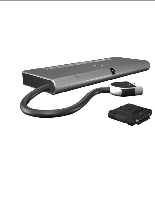
The HP Notebook QuickDock provides an efficient,
less-cluttered work environment and improved cable
management.
HP Notebook QuickDock and HP Expansion Accessory Adapter

1–2 Maintenance and Service Guide
Product Description
The HP Notebook QuickDock is compatible with the following
platforms:
■HP Pavilion dv9000 Notebook PC
■HP Pavilion dv6000 Notebook PC
■HP Pavilion dv2000 Notebook PC
■HP Pavilion tx1000 Entertainment PC
■Compaq Presario V6000 Notebook PC
■Compaq Presario V3000 Notebook PC
The following computers require use of the HP Expansion
Accessory Adapter to connect to the QuickDock:
■HP Pavilion dv8300 Notebook PC
■HP Pavilion dv8000 Notebook PC
■HP Pavilion dv5000 Notebook PC
■HP Pavilion dv4000 Notebook PC
■HP Pavilion dv1400 Entertainment Notebook PC
■HP Pavilion ze2000Notebook PC
■HP Compaq nx4820 Notebook PC
■HP Special Edition L2000 Notebook PC
■Compaq Presario V5000 Notebook PC
■Compaq Presario V4000 Notebook PC
■Compaq Presario V2000 Notebook PC
■Compaq Presario M2000 Notebook PC

Product Description
Maintenance and Service Guide 1–3
1.1 F e a t u r e s
■External AC adapter (charges docked computer)
■Security slot
■Lights (power connection and docking connection)
■Connectors:
❏Expansion cable
❏Audio-out (headphone) connector
❏Audio-in (microphone) connector
❏Universal Serial Bus (USB) 2.0 connectors (6)
❏Power connector
❏Component video jacks
❏S-Video-out
❏Composite video jack
❏S/PDIF (Sony/Philips Digital Interface) audio connector
❏External monitor port
❏RJ-45/Ethernet port
1–4 Maintenance and Service Guide
Product Description
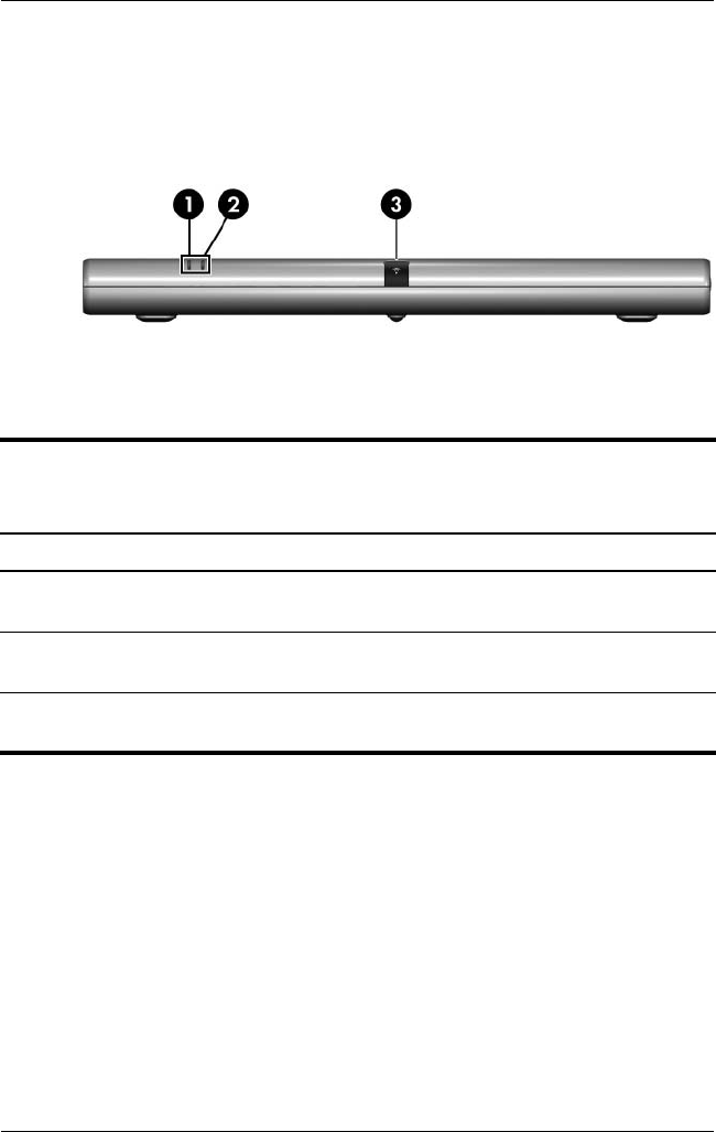
1.2 External Components
The external components on the front panel of the QuickDock are
shown below and described in Table 1-1.
Front Components
Table 1-1
Front Components
Item Component Function
1 Connection indicator
light
On: The computer is connected and
turned on.
2 AC power connect
light
On. The QuickDock is connected to
AC power.
3 Consumer infrared
lens
Detects the infrared signal of an optional
remote control.
Product Description
Maintenance and Service Guide 1–5
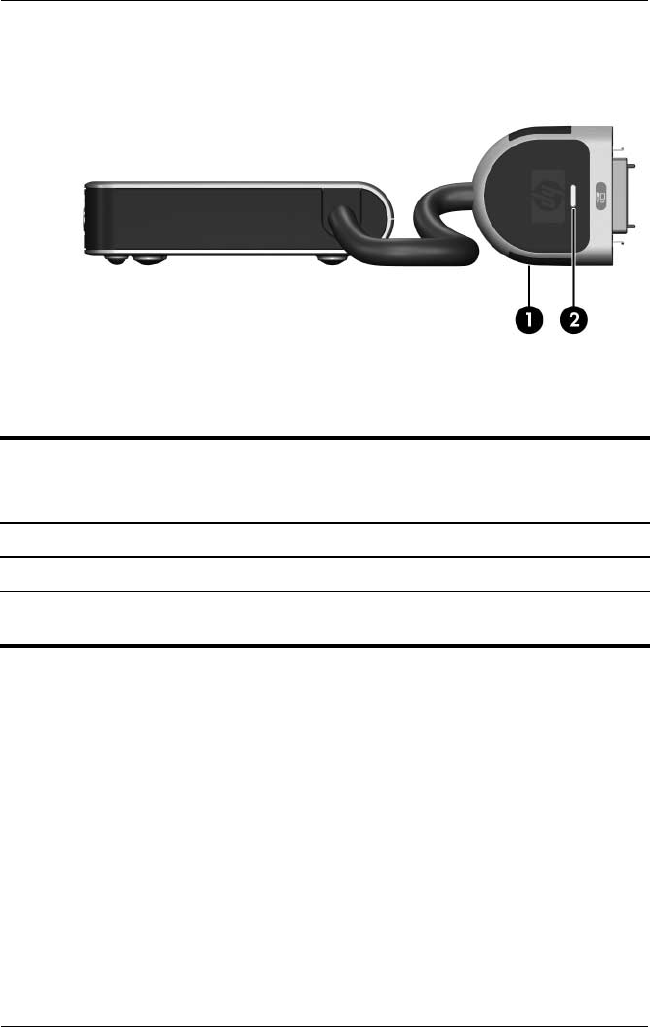
The external components on the left side of the QuickDock are
shown below and described in Table 1-2.
Left-Side Components
Table 1-2
Left-Side Components
Item Component Function
1 Expansion cable Connects the QuickDock to a computer.
2 Connection indicator
light
On: The computer is connected and
turned on.
1–6 Maintenance and Service Guide
Product Description
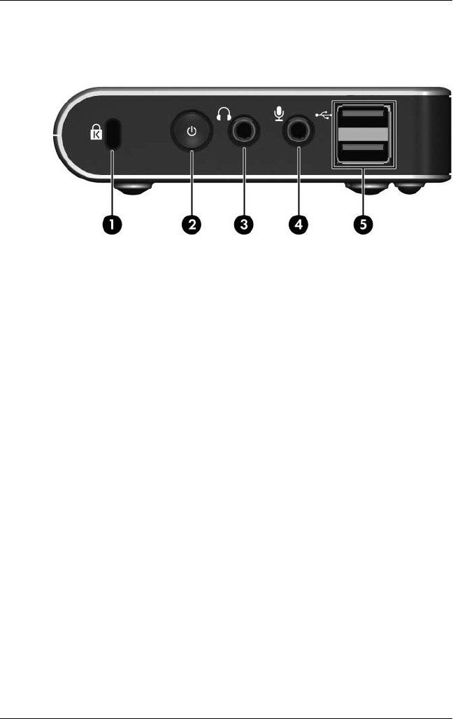
The external components on the right side of the QuickDock are
shown below and described in Table 1-3.
Right-Side Components

Product Description
Maintenance and Service Guide 1–7
Table 1-3
Right-Side Components
Item Component Function
1 Security cable slot Attaches an optional security cable to the
QuickDock.
✎The security cable is designed to
act as a deterrent, but it may not
prevent the computer from being
mishandled or stolen.
2 Power button Turns on the computer.
✎The power button on the QuickDock
has the same function as the power
button on the computer, even if the
computer display is closed.
3 Audio-out (headphone)
jack
Produces QuickDock sound when
connected to optional powered stereo
speakers, headphones, ear buds, a
headset, or television audio.
✎Speakers connected to the
QuickDock are muted when a
device is connected to the
headphone jack.
4 Audio-in (microphone)
jack
Connects an optional computer headset
microphone, stereo array microphone, or
monaural microphone.
5 USB ports (2)* Connect optional USB devices.
*There are 4 additional USB ports on the rear of the QuickDock.
1–8 Maintenance and Service Guide
Product Description
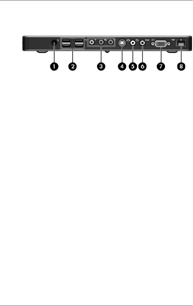
The external components on the rear panel of the QuickDock are
shown below and described in Table 1-4.
Rear Panel Components

Product Description
Maintenance and Service Guide 1–9
Table 1-4
Rear Components
Item Component Function
1 Power connector Connects the computer’s AC adapter or an
optional adapter.
2 USB ports (4)* Connect optional USB devices.
3 Component video
jacks (3)
Connect an optional component
video device.
4 S-Video-out jack Connects an optional S-Video device such
as a television, VCR, camcorder, overhead
projector, or video capture card.
5 Composite video jack Connects an optional composite
video device.
6 S/PDIF (Sony/Philips
Digital Interface)
digital audio jack
Connects an optional compatible
audio/video receiver through a digital
coaxial cable (purchased separately).
7 External monitor port Connects an optional external VGA monitor
or projector.
8 RJ-45 (network) jack Connects a network cable.
*There are 2 additional USB ports on the right side of the QuickDock.

1–10 Maintenance and Service Guide
Product Description
1. 3 D e s i g n O ve r v i ew
This section presents a design overview of key parts and features
of the QuickDock. Refer to Chapter 3, “Illustrated Parts Catalog,”
to identify replacement parts.
The QuickDock provides the following device connections:
■Expansion cable
■S/PDIF (Sony/Philips Digital Interface) audio connector
■Audio-out (headphone) jack
■Composite out
■RJ-11 (modem) connection (from telephone to QuickDock)
■RJ-11 (modem) connection (from QuickDock to computer)
■RJ-45 (network) port
■USB 2.0 connectors (3)
■S-Video-out
■Serial port
ÄCAUTION: To properly ventilate the QuickDock, allow at least a
7.6-cm (3-inch) clearance on the left and right sides of the unit.
The computer uses an electric fan for ventilation. The fan is
controlled by a temperature sensor and is designed to turn on
automatically when high temperature conditions exist. These
conditions are affected by high external temperatures, system
power consumption, power management/battery conservation
configurations, battery fast charging, and software.

Product Description
Maintenance and Service Guide 1–11
Connecting to AC Power
ÅWARNING: To reduce the risk of electric shock or damage to your
equipment:
■Plug the power cord into an electrical outlet that is easily
accessible at all times.
■Disconnect power from the product by unplugging the power cord
from the electrical outlet.
■If provided with a 3-pin attachment plug on your power cord, plug
the cord into a grounded (earthed) 3-pin outlet. Do not disable the
power cord grounding pin, for example, by using a 2-pin adapter.
The grounding pin is an important safety feature.
1–12 Maintenance and Service Guide
Product Description
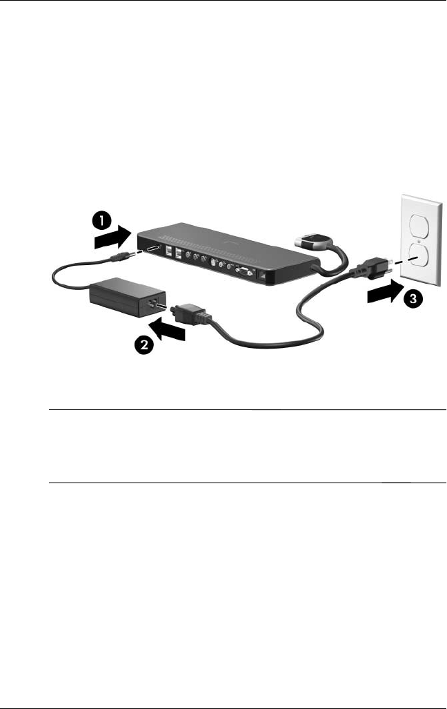
To ensure the correct performance of all QuickDock features,
connect the QuickDock to an AC power source using the
computer AC adapter and power cord.
1. Connect the computer AC adapter to the power connector
on the QuickDock 1.
2. Connect the AC power cord to the AC adapter 2.
3. Connect the AC power cord to the AC outlet 3.
Connecting the QuickDock to AC Power
✎Power cords and power outlets vary by region and country.
The AC adapter is included with the computer or is purchased
separately.

Product Description
Maintenance and Service Guide 1–13
Connecting the Computer
This section applies to the following computers:
■HP Pavilion dv9000 Notebook PC
■HP Pavilion dv6000 Notebook PC
■HP Pavilion dv2000 Notebook PC
■HP Pavilion tx1000 Entertainment PC
■Compaq Presario V6000 Notebook PC
■Compaq Presario V3000 Notebook PC
Refer to Section 1.4, “Using the HP Expansion Accessory
Adapter,” if you are connecting a computer that requires the
HP Expansion Accessory Adapter.
1–14 Maintenance and Service Guide
Product Description
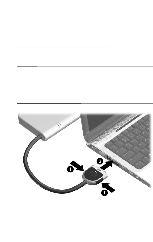
To connect the computer to the QuickDock:
1. Press the buttons on the sides of the expansion cable 1.
2. Connect the expansion cable to the computer 2, matching the
icon on the computer expansion port with the icon on the end
of the expansion cable.
ÄCAUTION: To prevent damage to the expansion port, be sure that
you correctly align the expansion cable to the expansion port on the
computer.
✎The location of the expansion port on your computer varies by
computer series and model.
The expansion port may also be called “expansion port 3” in the
computer user guide.
Connecting the Expansion Cable to the Computer
Product Description
Maintenance and Service Guide 1–15
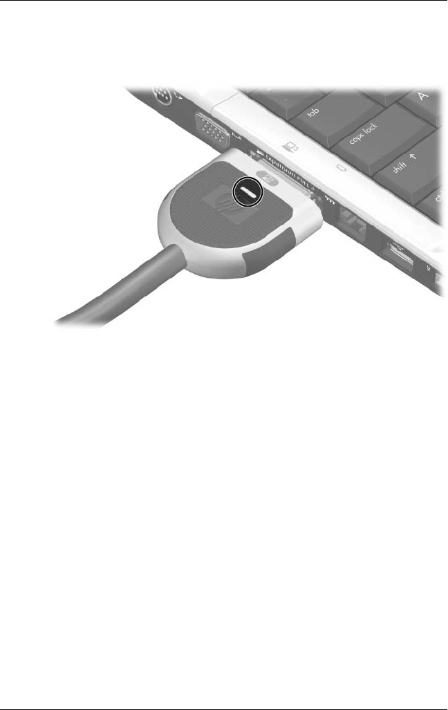
If the computer is on, the connection indicator light on the
expansion cable turns on.
Identifying the Connection Indicator Light
1–16 Maintenance and Service Guide
Product Description
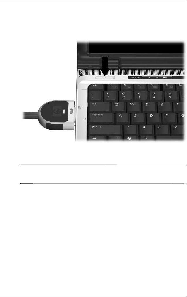
3. If the computer is not already turned on:
❏Press the power button on the computer.
Pressing the Computer Power Button
✎The power button location on the computer varies by computer
series and model.
Product Description
Maintenance and Service Guide 1–17
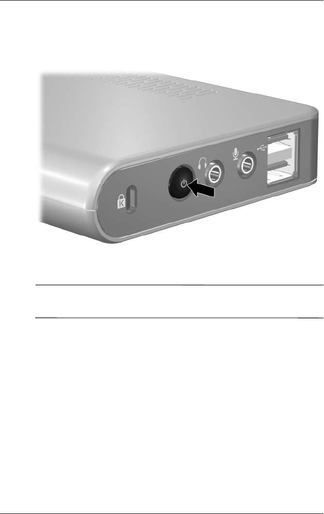
– or –
❏Press the power button on the QuickDock.
Pressing the QuickDock Power Button
✎The power button on the QuickDock allows you to turn the
computer on or off when the computer is closed.
1–18 Maintenance and Service Guide
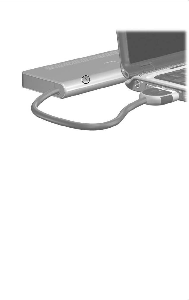
Product Description
The power light on the front of the QuickDock turns on.
Identifying the QuickDock Power Light

Product Description
Maintenance and Service Guide 1–19
1.4 Using the HP Expansion Accessory
Adapter
The following computers require use of the HP Expansion
Accessory Adapter to connect the computer to the QuickDock:
■HP Pavilion dv8300 Notebook PC
■HP Pavilion dv8000 Notebook PC
■HP Pavilion dv5000 Notebook PC
■HP Pavilion dv4000 Notebook PC
■HP Pavilion dv1400 Entertainment Notebook PC
■HP Pavilion ze2000Notebook PC
■HP Compaq nx4820 Notebook PC
■HP Special Edition L2000 Notebook PC
■Compaq Presario V5000 Notebook PC
■Compaq Presario V4000 Notebook PC
■Compaq Presario V2000 Notebook PC
■Compaq Presario M2000 Notebook PC
1–20 Maintenance and Service Guide
Product Description
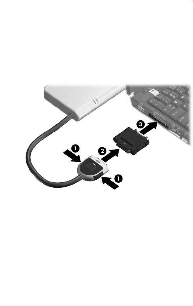
To connect a computer using the HP Expansion Accessory
Adapter:
1. Press the buttons on the sides of the expansion cable 1.
2. Connect the expansion cable to the expansion accessory
adapter 2, matching the icon on the expansion cable with
the icon on the end of the expansion accessory adapter.
3. Connect the expansion accessory adapter to the computer 3.
Connecting the HP Expansion Accessory Adapter

Maintenance and Service Guide 2–1
2
Troubleshooting
ÅWARNING: Only authorized technicians trained by HP should repair
this equipment. All troubleshooting and repair procedures are detailed
to allow only subassembly-/module-level repair. Because of the
complexity of the individual boards and subassemblies, do not attempt
to make repairs at the component level or modifications to any printed
wiring board. Improper repairs can create a safety hazard. Any
indication of component replacement or printed wiring board
modification may void any warranty or exchange allowances.
This chapter contains troubleshooting information for the
QuickDock. Carefully match the symptoms of the malfunction
against the problem description in the troubleshooting tables to
avoid a misdiagnosis. Refer to Chapter 5 for all removal and
replacement procedures.
Follow these guidelines when troubleshooting:
■Complete the recommended actions in the order in which
they are given.
■When the problem is resolved, do not complete the remaining
troubleshooting steps.
When troubleshooting a problem, check the following list for
possible solutions before requesting replacement:
■Be sure that cables are connected properly to the suspected
defective part.
■Be sure that all required device drivers are installed on the
computer.

2–2 Maintenance and Service Guide
Troubleshooting
Problems and Solutions
The following tables list possible problems, the possible cause of
each problem, and the recommended solution.
Table 2-1
General Use and Connection
Problems and Solutions
Problem Possible Cause Solution
The connection indicator
light is off.
The computer is not on. Turn on the computer.
The QuickDock is not
connected to AC power.
Connect the AC adapter
to the QuickDock and to
an AC outlet.
The expansion cable on
the QuickDock is not fully
connected to the
expansion port on the
computer.
Disconnect the
expansion cable from the
computer, and then
reconnect the cable to
the computer.
The computer is in
standby or hibernation.
Exit standby or
hibernation.

Troubleshooting
Maintenance and Service Guide 2–3
Table 2-1
General Use and Connection
Problems and Solutions
(Continued)
Problem Possible Cause Solution
The computer shuts
down unexpectedly.
The QuickDock is not
connected to AC power,
draining the computer
battery.
Connect the AC adapter
to the QuickDock and to
an AC outlet.
The ports or jacks on the
QuickDock are not
working.
The QuickDock is not
connected to AC power.
Connect the AC adapter
to the QuickDock and to
an AC outlet.
The computer is not
connected to the
QuickDock correctly.
Disconnect the
expansion cable from the
computer, and then
reconnect the cable to
the computer.

2–4 Maintenance and Service Guide
Troubleshooting
Table 2-2
Audio Problems and Solutions
Problem Possible Cause Solution
Headphones or other
audio device connected
to the QuickDock does
not produce sound.
Headphones or another
audio device is
connected to the
headphone jack on the
computer. Using the
headphone jack on the
computer mutes sound
through the QuickDock.
Disconnect the
headphones or other
audio device from the
headphone jack on the
computer.
More than one audio
device is connected to
the QuickDock.
Be sure that only one
audio device is
connected to the
QuickDock.
A microphone connected
to the computer does not
work.
A microphone is
connected to the
QuickDock. While a
microphone is connected
to the QuickDock, the
microphone jack on the
computer is disabled.
Either use the
microphone connected
to the QuickDock or
disconnect it.
A connected home
entertainment system
does not have audio.
Audio is not connected
properly.
Be sure that the
QuickDock is properly
connected to the home
entertainment system.
A connected home
entertainment system
does not experience
surround sound.
The home entertainment
system may not support
digital audio.
Be sure that your home
entertainment system is
S/PDIF compatible.
Refer to the user guide
for your home
entertainment device.

Troubleshooting
Maintenance and Service Guide 2–5
Table 2-3
Video Problems and Solutions
Problem Possible Cause Solution
A connected home
entertainment system
does not have video.
The video cable is not
connected correctly.
Disconnect and
reconnect the video
cable.
The screen image is
displaying on the
computer.
Press fn+f4 on the
computer to switch the
image from the computer
to the external display.
The QuickDock is not
connected to AC power.
Connect the AC adapter
to the QuickDock and to
an AC outlet.
The computer is not
connected to the
QuickDock correctly.
Disconnect the
expansion cable from the
computer, and then
reconnect the cable to
the computer.
A video device
connected to the
external monitor port on
the computer does not
work.
When the computer is
connected to the
QuickDock, the external
monitor port on the
computer is disabled.
Use the external monitor
port on the QuickDock.

2–6 Maintenance and Service Guide
Troubleshooting
Getting More Information
■For comprehensive information about your computer, as well
as governmental agency and safety information about the use
of your computer, access the Help and Support Center by
selecting Start > Help and Support.
■The HP Web site (http://www.hp.com) provides product news
and software updates.
Customer Care
If you cannot solve a problem using the troubleshooting tips
in this chapter, you may need to contact Customer Care.
For the fastest possible resolution of your problem, have the
following information available when you call or e-mail:
■The computer and QuickDock model types
■Serial numbers for the computer and QuickDock
■Dates the computer and QuickDock were purchased
■Conditions under which the problem occurred
■Error messages that have been displayed
■Hardware configuration of the computer
■Hardware and software you are using
■The manufacturer and model of the printer or other
accessories connected to the computer and QuickDock
■Configuration settings, including contents of the system files
To access Customer Care, visit the HP Web site at
http://www.hp.com/support.
Maintenance and Service Guide 3–1
3
Illustrated Parts Catalog
This chapter provides an illustrated parts breakdown and a
reference for spare part numbers and option part numbers.
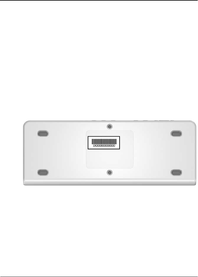
3.1 Serial Number Location
When ordering parts or requesting information, provide the
QuickDock serial number and model number located on the
bottom of the base plate.
Serial Number Location
3–2 Maintenance and Service Guide
Illustrated Parts Catalog
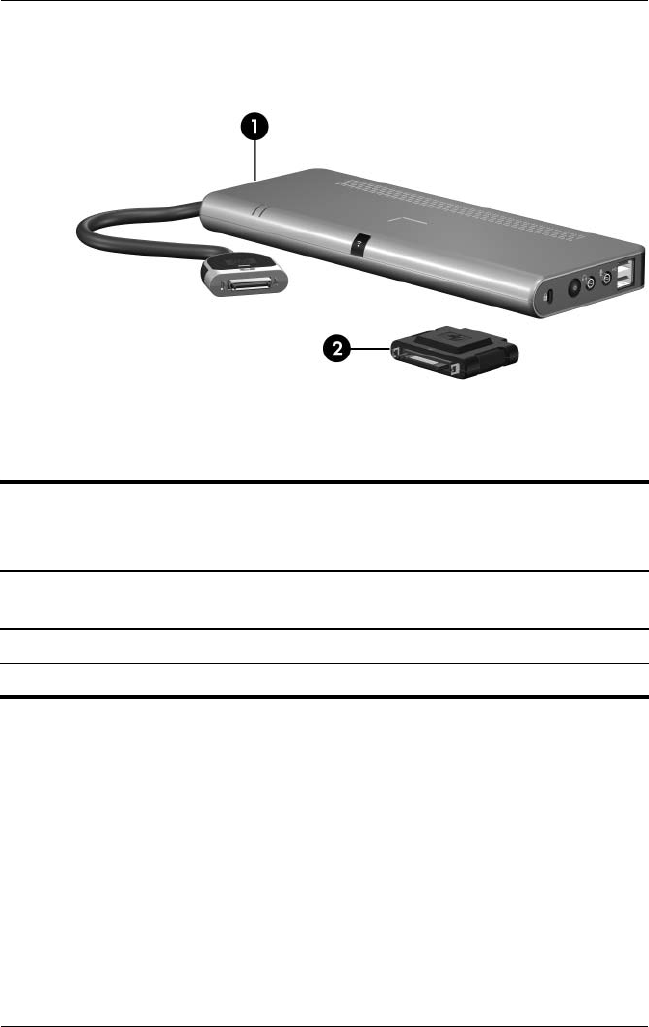
3.2 QuickDock Components
HP Notebook QuickDock Components
Table 3-1
Spare Parts: QuickDock Components
Item Description
Spare Part
Number
1HP Notebook QuickDock 430326-001
2HP Expansion Accessory Adapter 430327-001

Maintenance and Service Guide 4–1
4
Replacement Preliminaries
This chapter provides essential information for proper and safe
replacement service.
4.1 Tools Required
You will not need any tools to complete the replacement
procedures.
4.2 Service Considerations
The following sections include some of the considerations
that you should keep in mind during replacement procedures.

4–2 Maintenance and Service Guide
Replacement Preliminaries
4.3 Preventing Damage to
Removable Drives
Removable drives are fragile components that must be handled
with care. To prevent damage to the QuickDock, damage to a
removable drive, or loss of information, observe the following
precautions:
■Before removing or inserting a hard drive, shut down the
system (computer and QuickDock). If you are unsure whether
the system is off or in hibernation, turn the system on, and then
shut it down through the operating system.
■Before removing a diskette drive or optical drive, ensure that
a diskette or disc is not in the drive and ensure that the optical
drive tray is closed.
■Before handling a drive, ensure that you are discharged of
static electricity. While handling a drive, avoid touching the
connector.
■Handle drives on surfaces covered with at least one inch of
shock-proof foam.
■Avoid dropping drives from any height onto any surface.
■After removing a hard drive or MultiBay II device, place it in a
static-proof bag.
■Avoid exposing a hard drive to products that have magnetic
fields, such as monitors or speakers.
■Avoid exposing a drive to temperature extremes or liquids.
■If a drive must be mailed, place the drive in a bubble pack
mailer or other suitable form of protective packaging and label
the package, “FRAGILE: Handle With Care.”

Replacement Preliminaries
Maintenance and Service Guide 4–3
4.4 Preventing Electrostatic Damage
Many electronic components are sensitive to electrostatic
discharge (ESD). Circuitry design and structure determine the
degree of sensitivity. Networks built into many integrated circuits
provide some protection, but in many cases, the discharge
contains enough power to alter device parameters or melt
silicon junctions.
A sudden discharge of static electricity from a finger or other
conductor can destroy static-sensitive devices or microcircuitry.
Often the spark is neither felt nor heard, but damage occurs.
An electronic device exposed to electrostatic discharge might not
be affected at all and can work perfectly throughout a normal
cycle. Or the device might function normally for a while, then
degrade in the internal layers, reducing its life expectancy.

4–4 Maintenance and Service Guide
Replacement Preliminaries
4.5 Packaging and Transporting
Precautions
Use the following grounding precautions when packaging and
transporting equipment:
■To avoid hand contact, transport products in static-safe
containers, such as tubes, bags, or boxes.
■Protect all electrostatic-sensitive parts and assemblies with
conductive or approved containers or packaging.
■Keep electrostatic-sensitive parts in their containers until
the parts arrive at static-free workstations.
■Place items on a grounded surface before removing items
from their containers.
■Always be properly grounded when touching a sensitive
component or assembly.
■Store reusable electrostatic-sensitive parts from assemblies
in protective packaging or nonconductive foam.
■Use transporters and conveyors made of antistatic belts and
roller bushings. Ensure that mechanized equipment used for
moving materials is wired to ground and that proper materials
are selected to avoid static charging. When grounding is not
possible, use an ionizer to dissipate electric charges.

Replacement Preliminaries
Maintenance and Service Guide 4–5
4.6 Workstation Precautions
Use the following grounding precautions at workstations:
■Cover the workstation with approved static-shielding material
(refer to Table 4-2, “Static-Shielding Materials”).
■Use a wrist strap connected to a properly grounded work
surface and use properly grounded tools and equipment.
■Use conductive field service tools, such as cutters,
screwdrivers, and vacuums.
■When using fixtures that must directly contact dissipative
surfaces, only use fixtures made of static-safe materials.
■Keep the work area free of nonconductive materials, such
as ordinary plastic assembly aids and Styrofoam.
■Handle electrostatic-sensitive components, parts, and
assemblies by the case or PCM laminate. Handle these
items only at static-free workstations.
■Avoid contact with pins, leads, or circuitry.
■Turn off power and input signals before inserting or removing
connectors or test equipment.

4–6 Maintenance and Service Guide
Replacement Preliminaries
4.7 Grounding Equipment and
Methods
Grounding equipment must include either a wrist strap or a
foot strap at a grounded workstation.
■When seated, wear a wrist strap connected to a grounded
system. Wrist straps are flexible straps with a minimum of
one megohm ±10% resistance in the ground cords. To provide
proper ground, wear a strap snugly against the skin at all times.
On grounded mats with banana-plug connectors, use alligator
clips to connect a wrist strap.
■When standing, use foot straps and a grounded floor mat.
Foot straps (heel, toe, or boot straps) can be used at standing
workstations and are compatible with most types of shoes
or boots. On conductive floors or dissipative floor mats, use
foot straps on both feet with a minimum of one megohm
resistance between the operator and ground. To be effective,
the conductive strips must be worn in contact with the skin.
Other grounding equipment recommended for use in preventing
electrostatic damage includes:
■Antistatic tape
■Antistatic smocks, aprons, and sleeve protectors
■Conductive bins and other assembly or soldering aids
■Nonconductive foam
■Conductive tabletop workstations with ground cords of
one megohm resistance
■Static-dissipative tables or floor mats with hard ties to
the ground
■Field service kits
■Static awareness labels
■Material-handling packages
■Nonconductive plastic bags, tubes, or boxes
■Metal tote boxes
■Electrostatic voltage levels and protective materials

Replacement Preliminaries
Maintenance and Service Guide 4–7
Table 4-1 shows how humidity affects the electrostatic voltage
levels generated by different activities.
Table 4-2 lists the shielding protection provided by antistatic
bags and floor mats.
Table 4-1
Typical Electrostatic Voltage Levels
Relative Humidity
Event 10% 40% 55%
Walking across carpet 35,000 V 15,000 V 7,500 V
Walking across vinyl floor 12,000 V 5,000 V 3,000 V
Motions of bench worker 6,000 V 800 V 400 V
Removing DIPS from plastic tube 2,000 V 700 V 400 V
Removing DIPS from vinyl tray 11,500 V 4,000 V 2,000 V
Removing DIPS from Styrofoam 14,500 V 5,000 V 3,500 V
Removing bubble pack from PCB 26,500 V 20,000 V 7,000 V
Packing PCBs in foam-lined box 21,000 V 11,000 V 5,000 V
✎A product can be degraded by as little as 700 V.
Table 4-2
Static-Shielding Materials
Material Use Voltage Protection Level
Antistatic plastic Bags 1,500 V
Carbon-loaded plastic Floor mats 7,500 V
Metallized laminate Floor mats 5,000 V

Maintenance and Service Guide 5–1
5
Specifications
This chapter provides physical and performance specifications.
Table 6-1
HP Notebook QuickDock
Dimensions
Length
Width
Height
26.6 cm
10.0 cm
2.3 cm
10.74 in
3.94 in
0.91 in
Weight 0.97 kg 2.14 lbs
Temperature
Operating*
Nonoperating
5°C to 35°C
-20°C to 60°C
41°F to 95°F
-4°F to 140°F
✎Applicable product safety standards specify thermal limits for plastic
surfaces. The QuickDock operates well within this range of temperatures.
Relative humidity (noncondensing)
Operating
Nonoperating
10% to 90%
5% to 95%, 38.7°C (101.6°F) maximum
wet bulb temperature
Maintenance and Service Guide A–1
A
Connector Pin Assignments
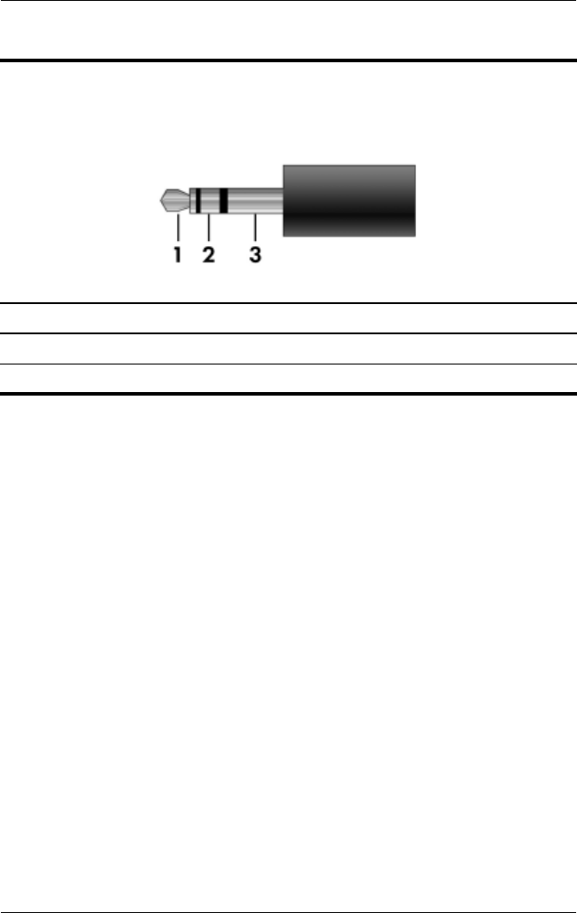
Table A-1
Audio-In (Microphone) Jack
Pin Signal Pin Signal
1 Audio signal in 3 Ground
2 Audio signal in
A–2 Maintenance and Service Guide
Connector Pin Assignments
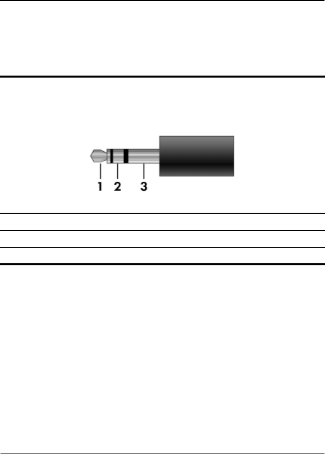
Table A-2
Audio-Out (Headphone) Jack
Pin Signal Pin Signal
1 Audio out, left channel 3 Ground
2 Audio out, right channel
Connector Pin Assignments
Maintenance and Service Guide A–3
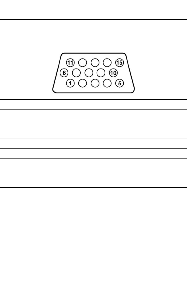
Table A-3
External Monitor Port
Pin Signal Pin Signal
1 Red analog 9 +5 VDC
2 Green analog 10 Ground
3 Blue analog 11 Monitor detect
4 Not connected 12 DDC 2B data
5 Ground 13 Horizontal sync
6 Ground analog 14 Vertical sync
7 Ground analog 15 DDC 2B clock
8 Ground analog
A–4 Maintenance and Service Guide
Connector Pin Assignments
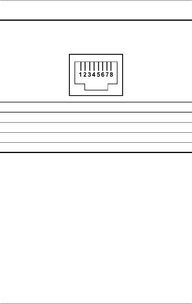
Table A-4
RJ-45 (Network) Jack
Pin Signal Pin Signal
1 Transmit + 5 Unused
2 Transmit – 6 Receive –
3 Receive + 7 Unused
4 Unused 8 Unused
Connector Pin Assignments
Maintenance and Service Guide A–5
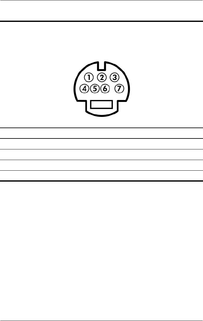
Table A-5
S-Video-Out Jack
Pin Signal Pin Signal
1 TV-Ground 5 TV-CD
2 TV-CVBS 6 TV-Ground
3 TV-Ground 7 TV-YD
4 TV-Ground

A–6 Maintenance and Service Guide
Connector Pin Assignments
Table A-6
Universal Serial Bus
Pin Signal Pin Signal
1 +5 VDC 3 Data +
2 Data – 4 Ground

Maintenance and Service Guide B–1
B
Power Cord Set Requirements
3-Conductor Power Cord Set
The wide range input feature of the QuickDock permits it to
operate from any line voltage from 100 to 120 or 220 to 240
volts AC.
The power cord set included with the QuickDock meets the
requirements for use in the country where the equipment
is purchased.
Power cord sets for use in other countries must meet the
requirements of the country where the QuickDock is used.

B–2 Maintenance and Service Guide
Power Cord Set Requirements
General Requirements
The requirements listed below are applicable to all countries.
■The length of the power cord set must be at least 1.5 m
(5.0 ft) and a maximum of 2.0 m (6.5 ft).
■All power cord sets must be approved by an acceptable
accredited agency responsible for evaluation in the
country where the power cord set will be used.
■The power cord sets must have a minimum current capacity
of 10 amps and a nominal voltage rating of 125 or 250 V AC,
as required by each country’s power system.
■The appliance coupler must meet the mechanical
configuration of an EN 60 320/IEC 320 Standard Sheet C13
connector for mating with the appliance inlet on the back of
the QuickDock.

Power Cord Set Requirements
Maintenance and Service Guide B–3
Country-Specific Requirements
3-Conductor Power Cord Set Requirements
Country/Region Accredited Agency Applicable Note Number
Australia EANSW 1
Austria OVE 1
Belgium CEBC 1
Canada CSA 2
Denmark DEMKO 1
Finland FIMKO 1
France UTE 1
Germany VDE 1
Italy IMQ 1
Japan METI 3
✎NOTES:
1. The flexible cord must be <HAR> Type HO5VV-F, 3-conductor, 1.0 mm²
conductor size. Power cord set fittings (appliance coupler and wall plug)
must bear the certification mark of the agency responsible for evaluation
in the country where it will be used.
2. The flexible cord must be Type SPT-3 or equivalent, No. 18 AWG,
3-conductor. The wall plug must be a two-pole grounding type with a
NEMA 5-15P (15 A, 125 V) or NEMA 6-15P (15 A, 250 V) configuration.
3. The appliance coupler, flexible cord, and wall plug must bear a “T” mark
and registration number in accordance with the Japanese Dentori Law. The
flexible cord must be Type VCT or VCTF, 3-conductor, 1.00 mm² conductor
size. The wall plug must be a two-pole grounding type with a Japanese
Industrial Standard C8303 (7 A, 125 V) configuration.

B–4 Maintenance and Service Guide
Power Cord Set Requirements
Korea EK 4
The Netherlands KEMA 1
Norway NEMKO 1
People’s Republic
of China
CCC 5
Sweden SEMKO 1
Switzerland SEV 1
Taiwan BSMI 4
United Kingdom BSI 1
United States UL 2
✎NOTES:
1. The flexible cord must be <HAR> Type HO5VV-F, 3-conductor, 1.0 mm²
conductor size. Power cord set fittings (appliance coupler and wall plug)
must bear the certification mark of the agency responsible for evaluation
in the country where it will be used.
2. The flexible cord must be Type SPT-3 or equivalent, No. 18 AWG,
3-conductor. The wall plug must be a two-pole grounding type with a
NEMA 5-15P (15 A, 125 V) or NEMA 6-15P (15 A, 250 V) configuration.
3. The appliance coupler, flexible cord, and wall plug must bear a “T” mark
and registration number in accordance with the Japanese Dentori Law. The
flexible cord must be Type VCT or VCTF, 3-conductor, 1.00 mm² conductor
size. The wall plug must be a two-pole grounding type with a Japanese
Industrial Standard C8303 (7 A, 125 V) configuration.
4. The flexible cord must be Type RVV, 3-conductor, 0.75 mm² conductor size.
Power cord set fittings (appliance coupler and wall plug) must bear
the certification mark of the agency responsible for evaluation in the country
where it will be used.
5. The flexible cord must be Type VCTF, 3-conductor, 0.75 mm² conductor
size. Power cord set fittings (appliance coupler and wall plug) must bear the
certification mark of the agency responsible for evaluation in the country
where it will be used.
3-Conductor Power Cord Set Requirements
(Continued)
Country/Region Accredited Agency Applicable Note Number

Maintenance and Service Guide Index–1
Index
A
AC power connect light 1–4
audio-in jack
location 1–7
pin assignments A–1
audio-out jack
location 1–7
pin assignments A–2
C
component video jacks 1–9
components
front 1–4
left-side 1–5
rear 1–8
right-side 1–6
composite video jack 1–9
connection indicator light 1–4,
1–5
connector pin assignments
audio-in jack A–1
audio-out jack A–2
external monitor port A–3
headphone jack A–2
microphone jack A–1
monitor port A–3
network jack A–4
RJ-45 jack A–4
S-Video-out jack A–5
Universal Serial Bus (USB)
port A–6
consumer infrared lens 1–4
D
design overview 1–10
drives, preventing damage 4–2
E
electrostatic discharge 4–3,
4–7
expansion accessory adapter
connecting 1–19
spare part number 3–2
expansion cable 1–5
external monitor port
location 1–9
pin assignments A–3
F
features 1–3
front components 1–4
G
grounding equipment and
methods 4–6

Index–2 Maintenance and Service Guide
Index
H
hard drive, precautions 4–2
headphone jack
location 1–7
pin assignments A–2
HP Expansion Accessory
Adapter
connecting 1–19
spare part number 3–2
HP Notebook QuickDock
components 3–2
spare part number 3–2
specifications 5–1
I
infrared lens 1–4
L
left-side components 1–5
M
microphone jack
location 1–7
pin assignments A–1
monitor port
location 1–9
pin assignments A–3
N
network jack
location 1–9
pin assignments A–4
O
optical drive, precautions 4–2
P
packing precautions 4–4
power button 1–7
power connector 1–9
power cord, set requirements
B–2
R
rear components 1–8
replacement preliminaries 4–1
right-side components 1–6
RJ-45 jack
location 1–9
pin assignments A–4
S
S/PDIF digital audio jack 1–9
security cable slot 1–7
serial number 3–1
service considerations 4–1
specifications 5–1
static shielding materials 4–7
S-Video-out jack
location 1–9
pin assignments A–5
T
tools required 4–1
transporting precautions 4–4
troubleshooting 2–1
U
Universal Serial Bus (USB)
port
location 1–7, 1–9
pin assignments A–6
W
workstation precautions 4–5
