HP ESKO_User_CA294 05780.fh9 Indigo Labels And Packaging Powered By Esko Artwork VDP Plug In User Guide C01484315
User Manual: HP HP Indigo Labels and Packaging powered by EskoArtwork - VDP Plug-in User Guide
Open the PDF directly: View PDF ![]() .
.
Page Count: 39

User Guide
HP Indigo Labels and Packaging powered by EskoArtwork
VDP Plug-in
User Guide
HP Indigo Labels and Packaging powered by EskoArtwork
VDP Plug-in
HP Indigo Labels and Packaging powered
by EskoArtwork
VDP Plug-in
User Guide

Printed in Israel
Copyright
© 2008 Copyright Hewlett-Packard
Development Company, L.P.
Reproduction, adaptation, or translation
without prior written permission is prohibited,
except as allowed under the copyright laws.
The information contained herein is subject
to change without notice.
The only warranties for HP products and
services are set forth in the express
warranty statements accompanying such
products and services. Nothing herein
should be construed as constituting an
additional warranty. HP shall not be liable for
technical or editorial errors or omissions
contained herein.
HP, HP Indigo Press, HP Indigo Press RIP,
and HP ElectroInk are trademarks or
registered trademarks of HP.
All other products or name brands are
trademarks of their respective holders.
Copyright 2007 Esko nv, Gent, Belgium
All rights reserved. Esko nv. does not warrant,
guarantee or make any representations
regarding the use, or the results of the use of
the software or the information contained
herein. Esko nv shall not be liable for any
direct, indirect, consequential or incidental
damages arising out of the use or inability to
use the software or the information contained
herein.
PANTONE Colors displayed here may not
match PANTONE-identified standards.
Consult current PANTONE Color Publications
for accurate color. PANTONE and other
Pantone, Inc. trademarks are the property of
Pantone, Inc. Pantone, Inc., 2000. Pantone,
Inc. is the copyright owner of color data and/or
software which are licensed to Esko nv to
distribute for use only in combination with LW-
Brix and CT-Brix based applications.
PANTONE Color Data and/or Software shall
not be copied onto another disk or into
memory unless as part of the execution of the
LWBrix and CTBrix based applications.This
software is based in part on the work of the
Independent JPEG Group.
This product includes software developed by
the Apache Software Foundation
(http://www.apache.org/)
Adobe, the Adobe logo, Acrobat, the Acrobat
logo, Adobe Creative Suite, Illustrator,
InDesign, PDF, Photoshop, PostScript, XMP
and the Powered by XMP logo are either
registered trademarks or trademarks of Adobe
Systems Incorporated in the United States
and/or other countries.
Microsoft and the Microsoft logo are registered
trademarks of Microsoft Corporation in the
United States and other countries.
"SolidWorks is a registered trademark of
SolidWorks Corporation."
Portions of this software are owned by Spatial
Corp. 1986 2003. All Rights Reserved.
JDF and the JDF logo are trademarks of the
CIP4 Organisation. Copyright 2001 The
International Cooperation for the Integration of
Processes in Prepress, Press and Postpress
(CIP4). All rights reserved.
The Esko software contains the "RSA Data
Security, Inc. MD5 Message-Digest
Algorithm".
Java and all Java-based trademarks and logos
are trademarks or registered trademarks of
Sun Microsystems in the U.S. and other
countries.
Confidentiality notice
This guide and any information contained
herein is confidential and should not be
disclosed to any third party outside of HP
Indigo. Do not copy and/or disseminate any
information contained in this guide. This
guide should be maintained in a manner
which shall ensure compliance with the
confidentiality requirements set forth herein.
This document contains valuable trade
secrets and confidential information of
Hewlett-Packard Company. Nothing herein
may be copied, reproduced or distributed in
any form or medium, or disclosed to any
third party in any manner, without prior
written authorization of Hewlett-Packard
Company. The copyright notice, which
appears in this document, is purely
precautionary and shall not be deemed to
constitute publication or intent to publish, in
whole or in part.
Part Number:
CA94-05780
First Edition:
February 2008
EN 3 Contents
Contents
Introduction.......................................................................................................................... 4
Components ........................................................................................................................ 4
The front end.................................................................................................................................... 5
The database ................................................................................................................................... 5
WorkFlow Manager tasks................................................................................................................. 7
DeskPack Workflow............................................................................................................. 8
Step 1: Create a job ......................................................................................................................... 8
Step 2: Prepare the data and task tickets ........................................................................................ 8
Step 3: Design a one-up in Adobe Illustrator ................................................................................. 11
Step 4: Step & Repeat and launch WorkFlow Manager tasks....................................................... 24
Configuration ..................................................................................................................... 30
FlexRip/Indigo Configuration.......................................................................................................... 30
DeskPack Configuration................................................................................................................. 32
Glossary............................................................................................................................. 33
4
Introduction
Variable Data Printing provides you the ability to print jobs with variable elements on digital presses
while keeping in mind the needs of the packaging industry.
A variable element can either be a text object, a barcode or an image.
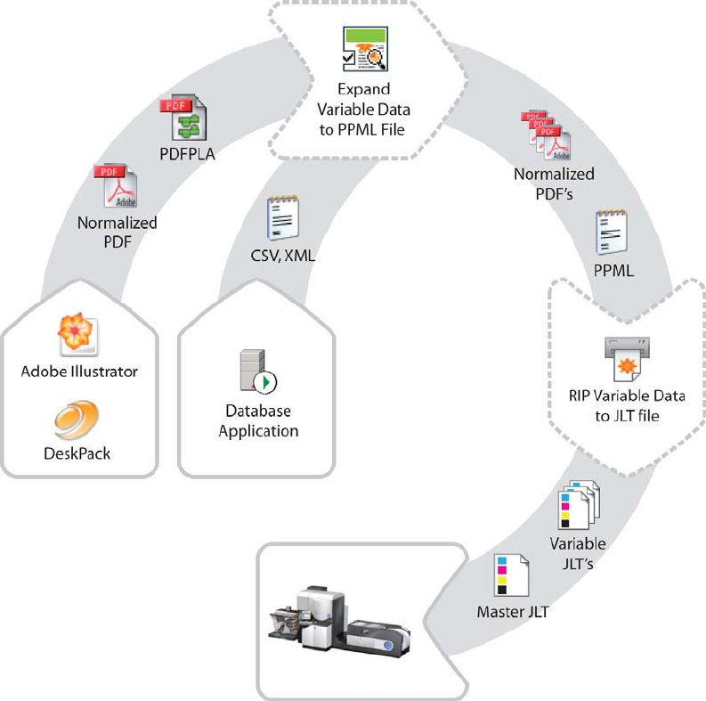
The Variable Data Printing process works as follows:
1. You can define these elements in a one-up document using Adobe Illustrator. Repetitions can
be defined using the StepX plug-in. Multiple grids with different one-ups per frame are
supported.
2. The WorkFlow Manager divides repeated one-ups into a static and a variable part, placing the
variable on top of the static part. The number of entries in the database defines the run length
of the job.
3. Based on the output generated by the workflow server, FlexRip creates bitmap files. FlexRip
can also apply HP Indigo Labels and Packaging Color Kit powered by EskoArtwork to a job.
4. Bitmaps are screened by the HP Indigo press itself.
This document will explain only the topics related to Variable Data Printing. Knowledge of WorkFlow
Manager Pilot and FlexRip is recommended.
Components
5 EN
The front end
The front end to the system consists of Adobe Illustrator and a set of DeskPack plug-ins.
The Variable Data plug-in is used to define variable elements within an open Illustrator document. For
this purpose, the concept of SmartMarks was introduced.
Introducing SmartMarks
SmartMarks are objects in the design that are linked to the database entries, and are generated
based on their contents. In other words, for various database records various SmartMark objects are
generated.
A SmartMark can be of three different types – a Text Mark, a Barcode Mark or an Image Mark:
• A Text Mark contains a text value and implements tools for its formatting;
• A Barcode Mark carries a bar code; and
• An Image Mark is used to place an image into the design, based on its file location.
Because the generation of variable elements is done on the server side, the plug-in needs to
cooperate tightly with the server, where all the graphic objects represented by SmartMarks are
created.
For this reason, a SmartMarks Preview task was introduced; its main purpose is to update the
SmartMark graphics objects and place them correctly into the design, to provide a comprehensive
preview during the actual designing process.
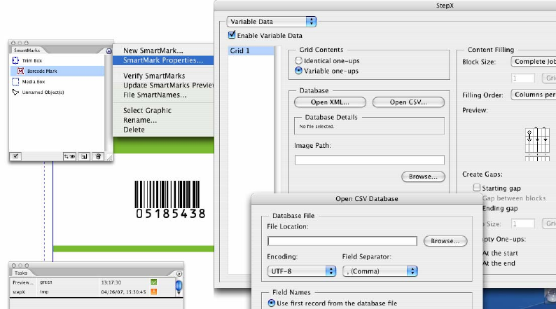
StepX for repetitions
For repetitions the StepX plug-in is used. In StepX, you can specify general repetition parameters,
such as plate and sheet size, horizontal and vertical steps, as well as variable-data-specific
parameters, such as the database parameters, ordering pattern, and gaps generation.
Front end output
The output of the front end consists of:
• A repetition file (PDFPLA file); and
• A one-up file (Normalized PDF file).
Server tasks are started via the StepX plug-in or the WorkFlow Manager Pilot application.
Much more detailed description of the front end and its features can be found in chapter
The database
Database input is limited to CSV or XML file format and must be stored using UTF-8 encoding.
CSV and XML files can be acquired from almost any database application; therefore other proprietary
file formats are not supported.
6
Field name requirements
When composing database field names you are restricted to alphanumerical characters or
underscores. The first character of a field name should not be a number.
The interpretation of field names is case insensitive. Uppercase letters will always be converted to
lowercase during import.
XML document structure requirements
The XML document structure should look like this:
<?xml version=“1.0“ encoding=“UTF-8“?>
<rootElem>
<recordElem>
<fieldName1>FieldValue-1-1</fieldName1>
<_fieldName2> FieldValue "1-2"</fieldName2>
</recordElem>
<recordElem>
<fieldName1></fieldName1>
<_fieldName2>FieldValue-2-2</fieldName2>
</recordElem>
</rootElem>
The names of the XML elements are arbitrary, but the following rules must be observed:
• Field name elements must conform to the rules for valid field names listed above.
• The amount and type of field name elements must be the same for each record.
Note: The use of element attributes in the XML database is not forbidden, but they are not interpreted
by our solution in any way.
A correct XML file can easily be exported from Microsoft Access. Microsoft Excel XML files are not
supported.
CSV format requirements
An example of the CSV format for the same database is provided below:
fieldName1,_fieldname2
FieldValue-1-1,"FieldValue ""1-2"""
,FieldValue-2-2
Aside from the standard rules creating CSV formatted files, the following must be taken into account:
• Field names must conform to the rules for valid field names listed above.
• Each record (line) must have the same number of fields, equal to the number of field
names.
• Newline characters in field values are not supported (if you want to use a newline character in
Text Mark, use the standard '[nl]' control sequence).
Field names can be extracted either from the first record of the CSV file, or can be provided in a
separate CSV file.
The delimiter character can be a comma, semicolon, space or a tab character, with the comma being
the default.

7 EN
WorkFlow Manager tasks
The WorkFlow Manager offers three tasks to handle variable data:
• The SmartMarks Preview task;
• The Expand Variable Data to PPML File (DeskPack only) task;
• The RIP to WS4000 Series task.
SmartMarks Preview task
The SmartMarks Preview task generates the variable graphic objects at the stage of designing a
variable data document in Illustrator. This task can be executed only from the Variable Data plug-in,
and cannot be found in the WorkFlow Manager Pilot application.
Expand Variable Data to PPML File (DeskPack only)
The Expand Variable Data to PPML File (DeskPack only) task performs expansion of the specified
database entries into the corresponding graphical output.
The task takes the following input
files…
And it generates these output files…
• a design file containing variable
elements (Normalized PDF file);
• a repetition file generated by the
StepX plug-in (PDFPLA file); and
• and a database file (XML or
CSV)
• one file with constant (unchanging)
graphic elements (Normalized PDF file);
and
• several files with variable graphic
elements (Normalized PDF files).
All these files are linked together by a
standard PPML file.
RIP to ws4000 Series
The RIP to ws4000 Series task triggers FlexRip to create HP Indigo proprietary JLT files.
These files can be read only by an HP Indigo press. The main difference compared to the generic RIP
tasks is that this task supports PPML files, which is essential for correct variable data interpretation.
8
DeskPack Workflow
There are several ways to prepare documents and data for Variable Data Printing. However, it is
recommended to conform to the following workflow:
1. Create a job.
2. Prepare the data and task tickets.
3. Design a one-up in Adobe Illustrator.
4. Perform Step & Repeat and launch the WorkFlow Manager tasks.
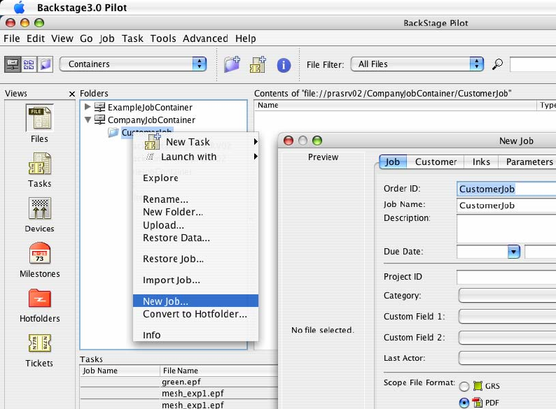
Step 1: Create a job
In the WorkFlow Manager Pilot, create a new job or use an existing job, which will be used to
encapsulate the variable data resources.
This job should contain a one-up document containing the design with variable elements definitions,
and all the documents which are created during the workflow process (such as a StepX preferences
file, PDF files for both fixed and variable parts of the job and a linking PPML file). In addition, input
data (database files and images) is also often stored in the Job folder.
Step 2: Prepare the data and task tickets
The next step is to prepare the WorkFlow Manager task tickets that will be used for variable data
expansion and consequential ripping.
Expand Variable Data to PPML File task
The first task to consider is the 'Expand Variable Data to PPML File (DeskPack only)' task, which is
the first task in the workflow chain. It is executed directly from within StepX.
In most cases, the expansion task is followed directly by the ' RIP to ws4000 Series' task, so the use
of a chained workflow ticket for both tasks is recommended. However, independent use of the
9 EN
expansion task is also possible (i.e. in case you only care about the expansion output, but do not want
to run the RIP task afterwards).
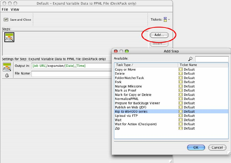
You should specify an output folder for the 'Expand Variable Data to PPML File (DeskPack only)'
task, otherwise the files are written into the DeskPack container and an error may occur.
The Jobfolder is a suitable location for this, and since you can use SmartText in the folder location,
you can create a path similar to this: [joburl]/expansion/[date]_[time].
Please note that the contents of this folder must be maintained manually as the files are not deleted
automatically.
10
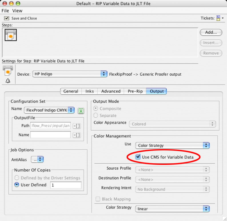
RIP to ws4000 Series task
When the expansion task finishes, the 'RIP to ws4000 Series' task can be started to launch FlexRip.
There are only two minor differences in the ticket dialog compared to a generic ripping/proofing task.
• In the Inks tab of the ticket dialog the option Use varnish inks in output was added. This
option enables or disables interpretation of the Varnish-type inks by the RIP.
• In the Output tab of the ticket the option Use CMS for Variable Data was added.
This option allows using color management also for the variable data elements, instead of just
color managing the fixed background. If the variable data are put in a Pantone or a designer
ink and the option is turned off, the inks will be converted by using the color strategy ‘linear’.
Please note that turning on color management for variable data slows down the performance
significantly.
Note: For a description on all the options of the RIP task, please refer to the WorkFlow Manager
documentation.
If the RIP to ws4000 Series task finishes successfully, the temporary files from the expansion task can
be deleted. These files are not deleted automatically.
11 EN
Step 3: Design a one-up in Adobe Illustrator
A design for Variable Data Printing consists of two main parts: fixed graphic elements forming the
background and variable elements placed on top of them.
Because merging the variable and fixed parts is not performed by the WorkFlow Manager, placing
fixed graphics on the top of the variable graphics is not supported.
All variable elements are created as SmartMarks. All other elements will be stored in a fixed
background.
Design requirements
While designing the document, the following rules have to be obeyed:
• The fixed background elements must not be located in the layer named Variable_Data.
• The SmartMarks placed in the Variable_Data layer must not be edited using the built-in
Illustrator tools (except of the selection tool, which can be used to reposition SmartMarks).
• The Variable_Data layer always remains the top layer in the document.
Creating SmartMarks with the Variable Data plug-in
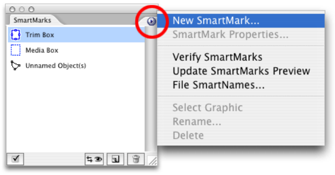
To create the SmartMarks, go to Window Æ Esko Æ Variable Data to launch the Variable Data plug-
in.
The SmartMarks palette, which is the main working area of Variable Data appears.
You can only create a SmartMark object if the file contains trim and media box definitions.
Trim and media box definitions can be added using the DeskPack Trim Box and Media Box plug-in.
Also, keep in mind that at least one ink should be used in the document’s fixed part, so that this
ink can be used by a SmartMark object.
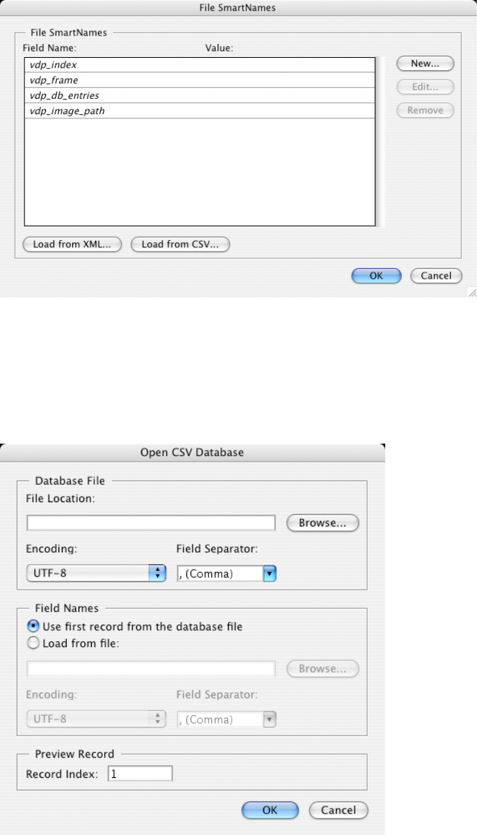
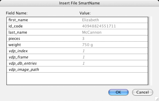
Defining File SmartNames
Select File SmartNames… from the SmartMarks palette’s menu to define File SmartNames. File
SmartNames provide a link between the SmartMarks’ values and the actual database values that are
used during the expansion.
Designers do not need access to the real database used for printing. However, they must be able to
obtain the correct field names, since these are essential when identifying the specific database
columns.
You can either:
• Use a dummy database file; or
• Enter the field names and preview values manually.
12
Using a dummy database file
Typically, the field names along with some preview values (the values used while designing the one-
up) are loaded from a database file:
• Click Load from XML to load an XML database file; or
• Click Load from CSV to load a CSV formatted file.
For XML files, only the file location and record index are specified. CSV format files need additional
information concerning the field separator, and the possibility of field names being defined in a
separate CSV file.
13 EN
Defining File SmartNames manually
You can also manually define File SmartNames by clicking the 'New...', 'Edit…' and 'Remove' buttons.
However, be careful not to misspell the column names, because during expansion only the entries in
the database that match these field names will be processed.
Very long SmartName values may be truncated in the dialog box, but this has no influence on reading
SmartNames from database files and the expansion will handle long values correctly.
Please read the chapter before you submit your first database.
Apart from the user-defined SmartNames, the following SmartNames are available:
• vdp_index – returns the number of the used database record, starting with 1
• vdp_frame – returns the number of the current frame generated by the expansion task
• vdp_db_entries – returns the total count of all entries in the current database file
• vdp_image_path – returns a path to a folder (see Image Mark for more information)\
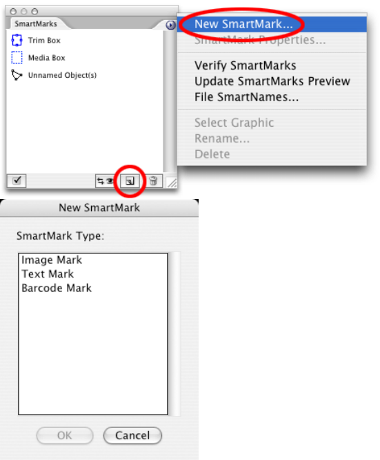
Inserting New SmartMarks
Once we have File SmartNames defined, we can create first SmartMark.
To create a new SmartMark select the 'New SmartMark…' item from the fly-out menu of the palette, or
click the shortcut icon in the bottom area of the palette.
SmartMarks are divided into three types: Text Mark, Image Mark and Barcode Mark.
Inserting Text Marks
A Text Mark is used to generate variable text elements.
The first page of the Text Mark Properties dialog allows the user to define a text value for a variable
text element and to choose formatting and aligning of the text within the specified text box.
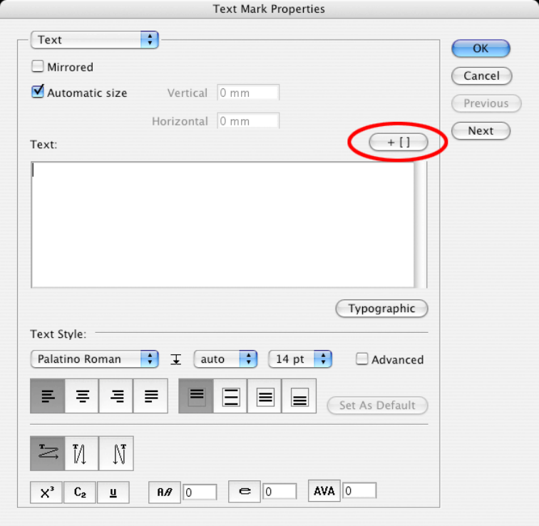
14
You can:
• Use the button '+ []' to insert a File SmartName into the text value. Once a File SmartName
is used in the Text Mark, the Text Mark carries variable information – for each record of the
database the Text Mark will be expanded into a different value. For design purposes, the
value specified in the File SmartNames dialog will be used. The inserted File SmartName is
displayed in the input field as [f.fieldname].
15 EN
• Format the text in the 'Text' input field by selecting the appropriate options in the Text Style
area:
o Every change is applied to the whole text, unless the option Advanced is enabled. In
this case formatting strings can be pasted into the text to apply the changes only on
segments of the Text Mark’s value.
o Special characters can also be inserted using the button Typographic.
• Mirror the contents of the SmartMark by enabling the Mirrored option.
• Specify custom text box dimensions or enable automatic sizing of the text box by
enabling or disabling the Automatic Size option.
Note: Only fonts installed on the WorkFlow Manager server can be used with Text Mark. Font
Manager is used for font importing.
Note: The Inks and Position pages of the dialog are explained in separate chapters, as they are
almost identical for all the three SmartMark types.
Inserting Barcode Marks
A Barcode Mark is used to generate variable barcode elements.
The first page of the Barcode Mark Properties dialog allows the user to choose a type, define a value
and some additional options for a variable barcode.
16
The following types of barcodes are supported:
• 2 of 5
• CLF-8
• CODABAR
• CODE 128
• CODE 128 (long)
• CODE 39
• DATAMATRIX
• EAN 128
• EAN 13
• EAN 8
• HIBC 128
• HIBC 39
• ITF-14
• ITF-16
• Int. 2 of 5
• Laetus Pharma Code
• M+S 7
• MSI
• Marks & Spencer
• PZN
• Paraf Italy
• UPC-A
• UPC-E
EN 17 DeskPack Workflow
Every code has its own set of attributes.
You can:
•
Enter the barcode value in the Code field. Use the '+ []' button to insert a File SmartName into the
barcode value.
•
Enable the generation of readable characters under the barcode element by enabling or
disabling the Characters option.
•
Create a masking white rectangle around the barcode to ensure legibility of the barcode by
enabling the Box option
Note: For more information on all the specific barcode options, please consult the barX documentation.
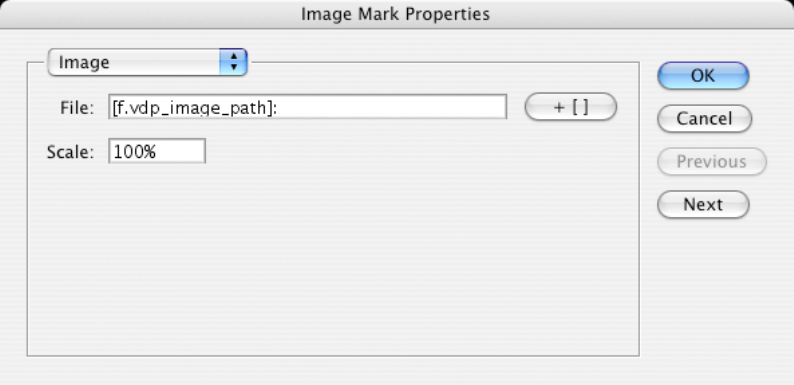
Inserting an Image Mark
An Image Mark is used to insert variable bitmap or vector-based images into the design based on their file
locations.
The first page of the Image Mark Properties dialog contains the File field, which specifies the location of the
image.
Use the '+ []' button to insert a File SmartName into the File field’s value. The
vdp_image_path
File
SmartName is already prefilled for you. This SmartName can be configured in the File SmartNames dialog
and allows the user to specify a folder path, where all the variable images are located.
Example
The full path to an image looks like this:
\\server\share\customer\job\images\image1.ct
Use
vdp_image_path
to specify the fixed part of the path:
\\server\share\customer\job\images\
(Local addresses are translated to network addresses automatically.)
Then, in the ImageMark settings, you can specify the full path as follows:
[f.vdp_image_path]\image[vdp_index].ct
Using
vdp_image_path
is recommended since it makes your job more portable. If the variable job is
moved to another Jobfolder, it is sufficient to change the document’s image path SmartName and the correct
value for all the Image Marks is reestablished.
18 EN
The Scale option provides the possibility of changing the size of the Image Mark, relatively to its original
print size.
When variable images are used in the design, the files must be stored in a container so that the WorkFlow
Manager can reach them. It is recommended to store all the images in a Jobfolder. If the same set of
images is used in multiple jobs it is possible to store them only once and reuse them from all jobs.
EN 19 DeskPack Workflow
Image requirements:
•
All images must be in CT or Normalized PDF format, and they must not use RGB or LAB color
space. Other file types can be converted into the CT format using the Import Image task on the
WorkFlow Manager.
•
Clipping paths and alpha channels are not supported for bitmap file formats.
•
Also, based on the option defined in the Inks page, all the images must be either multi-channel or
single-channel, as mixing of different color-spaced images is not allowed.
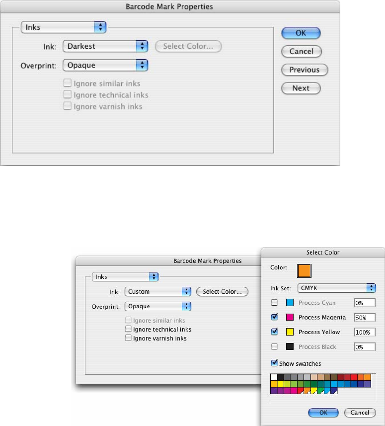
Setting Inks options on the Inks page
The Inks page of the SmartMark Properties dialog allows the user to define an ink or a color (combination
of inks) which will be used for the specific SmartMark object. The options for Text Marks and Barcode Marks
are identical; ink options for Image Marks are a little different.
The Inks page for Text Marks and Barcode Marks provides the user with the following options:
•
Ink – the inks being used for the current SmartMark
o
Custom – a user can define custom color to use. It is possible to choose either from all the
inks used in the document (including spot colors), or from predefined ink sets such as CMYK,
HP IndiChrome or HP IndiChrome Plus. A percentage of each ink can be chosen, and a
preview of the resulting color is generated.
For CMYK colors, it is also possible to use swatches as a reference – an easy way to
guarantee the required color. Moreover, if the swatch is made global, a link between the
SmartMark and a swatch name can be established. In this case, if the swatch color is
changed, the color of the SmartMark will be updated as well. The link can be destroyed by
clicking on the broken chain icon once it has been established.
20 EN
o
Darkest – sets the fill of the object to 100% of the darkest ink used in the document. Please
note that the Black is not always the darkest ink. Certain Pantones might be darker.
o
Knockout – the object fill is set to white so the background will be masked out.
•
Overprint – overprint mode being used for the current SmartMark
o
Opaque – this option will have the SmartMark object to knock out any object located
underneath it.
o
PostScript – the object will behave according to the PostScript overprint definition.
•
Ignore Similar Inks – an ink with different variants of screening or lineature is used only once. This
feature is not important for digital printing.
•
Ignore Technical Inks – inks of which the group type is set to 'Technical' are ignored for this
SmartMark.
•
Ignore Varnish Inks – inks of which the group type is set to 'Varnish' are ignored for this SmartMark.
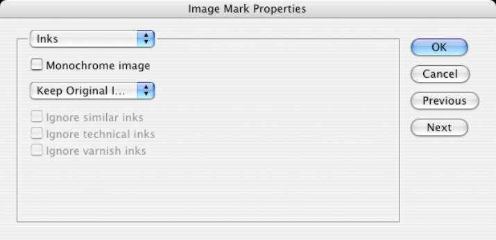
The ink options for Image Marks are identical to those of Text Mark and Barcode Mark only when the
Monochrome Image option is turned on. In this case, the ink defined in the image file is ignored and the ink
specified in the SmartMark Properties dialog is used.
However, multichannel images are also supported – the Monochrome Image option must be turned off
and the user is presented with the following options:
•
Keep Original Inks – the Image Mark will use inks defined in its document, so the appearance will
not be changed.
•
Map Inks – ink no. 1 from the one-up will be mapped onto ink no. 1 from the image file, etc. Note that
the appearance of the Image Mark may change dramatically. 'Ignore Ink' conditions can be set for this
option being enabled.
•
Keep Ink Names – inks will appear only if they are present in the one-up document.
As mentioned before, when you are not using predefined ink sets such as CMYK or HP IndiChrome, only
the inks which are part of the job can be assigned to a SmartMark.
To work around this limitation you can define an object with the requested ink outside of the Media Box of the
document. The ink will then become part of the job and can be assigned to any SmartMark object.
If a SmartMark contains a spot ink that will later be converted into a color space of the Indigo press it is not
advised to use PostScript overprint. Opaque should be used instead. Separation into inks of the press
EN 21 DeskPack Workflow
combined with PostScript overprint might cause the SmartMark to disappear. This rule also applies in case
CMS is involved.
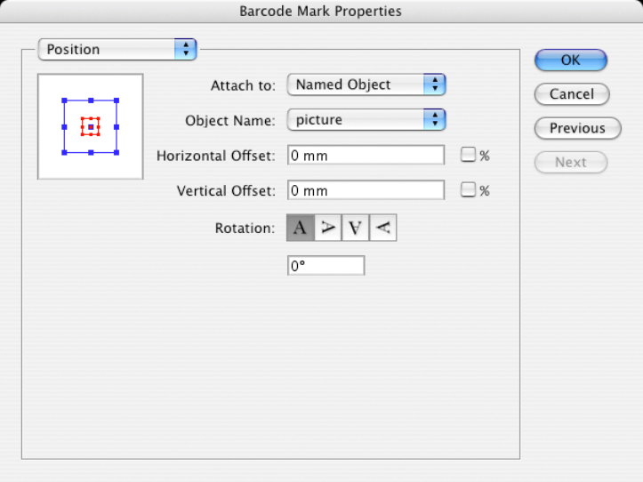
Setting Position properties on the Position page
Position is always specified relative to an object. When the size or position of the referenced object is
changed, the position of the attached SmartMark will be updated accordingly.
The page contains the following options:
•
Position diagram – here the relative position of the SmartMark to the reference object can be set.
Click the diagram to change the position.
•
Attach to – defines the reference object for determining the SmartMark’s position.
o
Trim Box – the SmartMark is referenced to the Trim Box of the document.
o
Media Box – the SmartMark is referenced to the Media Box of the document.
o
Named Object - the SmartMark is positioned relatively to a Named Object. A Named Object
can be another SmartMark with a custom name, or a graphic element or a group of graphic
elements contained in the design with an assigned name. The name can be assigned to an
object using the SmartMarks palette options. It should not be longer than 100 characters.
•
Object name – here a specific Named Object for Attach to / Named Object option is chosen.
•
Horizontal and Vertical Offset - the offset of the SmartMark from the referenced object.
•
Rotation – Rotation of the SmartMark object.
Working with Named Objects
When determining the position of SmartMarks, you must attach the marks either to the Trim Box, the Media
Box, or to a Named Object.
To create a Named Object:
1. Select the desired graphic object using the Illustrator‘s selection tool. An Unnamed Objects(s) item
appears in the SmartMarks palette.
2. Rename the unnamed object by clicking the Rename... command in the palette’s fly-out menu. This
will assign a new name to the object.
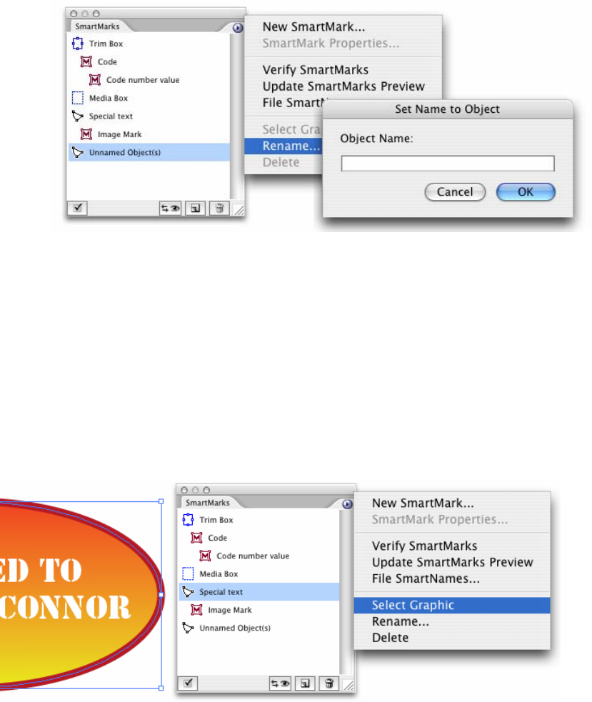
22 EN
From this moment, SmartMarks can be attached to the newly created Named Object.
Renaming an existing object is done exactly the same way: firstly select the desired object in the SmartMarks
palette, then rename it. The use of in-place editing of the object names in the SmartMarks palette is also
possible.
Named objects can be either static objects contained in a design, or SmartMarks.
For SmartMarks, you can create even longer dependency chains. This is particularly useful in case the
position of a SmartMark is dependent on a position of another SmartMark, but since SmartMarks are variable,
the exact position cannot be resolved at a design time.
If you want to move the whole tree of such dependencies, or you are just dealing with a too complex
document, you can take advantage of the feature Select Graphic, which selects the graphic objects in the
Illustrator document that corresponds to the selected SmartMarks palette item.
To delete a Named Object, use the Delete command on the fly-out menu. However, this functionality
behaves differently for static Named Objects and for SmartMarks:
•
Choosing Delete for static objects deletes just the name of the object; the graphics data of the
object are preserved.
EN 23 DeskPack Workflow
•
Choosing Delete for SmartMarks deletes the complete SmartMark, along with its graphic data. Any
SmartMarks attached to the object being deleted are re-attached to the Trim Box by default.
Viewing your SmartMarks with the preview task
A SmartMark object can be moved with Illustrator tools. Each position change will automatically update the
position offsets in the SmartMark Properties dialog box.
However, for any other change to SmartMarks (such as change to text formatting, new ink assignment or a
new rotation angle) the preview needs to be regenerated.
Also, for the initial creation of SmartMark objects the intervention of the WorkFlow Manager is required.
The Update SmartMarks Preview task is used for this purpose.
Please note that even though the Variable Data plug-in is able to perform position offsets updating without the
need to run the preview task, for the expansion the positions generated by the preview task are always taken
into account.
This is why it is recommended to always run the preview task at the end of the design process, to make
sure that the final output will be in sync with the result displayed in Adobe Illustrator.
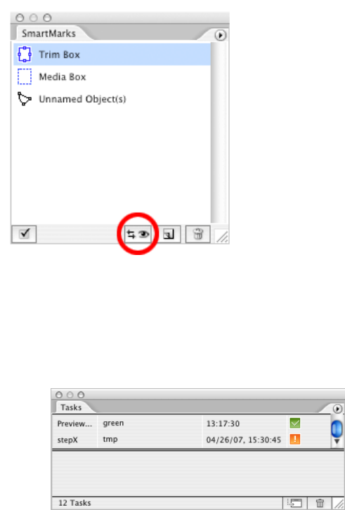
Running the Update SmartMarks Preview task
As already mentioned, SmartMarks are not generated by the Adobe Illustrator itself, but by the WorkFlow
Manager. To regenerate the SmartMarks, you have to run the Update SmartMarks Preview task.
Running the task will:
•
Send the one-up to the WorkFlow Manager;
•
Save and close the document to prevent the user from modifying the design while the preview is
being generated;
•
Display the Tasks palette, showing the progress of the task. Once the task has finished, the
document with regenerated SmartMarks can be re-opened by double-clicking the task‘s row in the
Task palette.
SmartMarks consistency
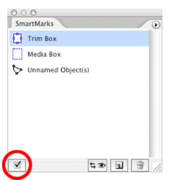
24 EN
You should not modify the contents of the Variable_Data layer directly, because by doing so, the
consistency of the SmartMark objects may be impaired.
This is also why the Verify SmartMarks feature of the Variable Data plug-in is run just before launching the
actual preview task. This feature checks whether the state of SmartMarks is consistent and shows a warning
dialog if any inconsistencies are detected.
A user can also check the consistency of SmartMarks manually without the need to run the preview task, by
clicking the Verify SmartMarks menu item. It can be used to synchronize the contents of the SmartMarks
palette with the actual state of the document.
Reviewing our work so far
Up to this point in the workflow, we have:
•
prepared a database;
•
used the database to define File SmartNames in the Variable Data plug-in;
•
created a SmartMark of the preferred type and desired attributes; and
•
visualized the SmartMark by running the 'Update SmartMarks Preview' task.
To be able to define the positions of SmartMarks more in accordance with their mutual relationship, the
concept of creating Named Objects is introduced.
Step 4: Step & Repeat and launch WorkFlow Manager
tasks
Once the variable design is created using the Variable Data plug-in, a repetition must be made. A repetition
(Step and Repeat) is performed by the StepX plug-in.
EN 25 DeskPack Workflow
The variable data-specific options are added to the StepX user interface as a new dialog page and offer the
possibility to specify the expansion parameters. If the Enable Variable Data option is turned off, StepX will
work exactly the same way as it would without the Variable Data Printing license. However please note, that
the Alternate option is not supported if the 'Enable Variable Data' option is turned on.
Note: For general information on the StepX functionality and all of its parameters, please consult the StepX
documentation. A detailed explanation of all the variable data-specific options follows.
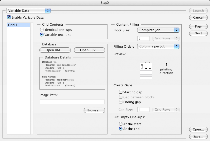
Multiple grids
For variable data, multiple grids are supported. The VDP parameters must be specified for each grid
individually.
To specify the parameters for a grid, select the grid on the left side of the page. The options for the grids do
not depend on each other, so a change of parameters for one grid will never influence the output of another
grid on a frame.
Grid Contents
The expansion task can handle two types of grid contents:
•
Identical One-ups – does not include any variable elements. It may be used to fill the empty space
on a substrate that is not used by variable data.
•
Variable One-ups – carries the design with variable data elements. The main difference for these
two types of contents is the absence of a database specification and ordering pattern possibilities for
the 'Identical One-ups' option.
Database
This parameter defines the database which will be used for expansion. The database file can be different from
the one used for loading File SmartNames.
The only requirement is that the identical column names are used. The database can be either in XML or a
CSV file format and must use the UTF-8 encoding. See chapter XXX (Database) for more information.
26 EN
XML Database
This type of database is a file in the eXtensible Markup Language format. Clicking ‘Open from XML...’ opens a
file browser, which allows you to select the XML file.
Please note that the XML file must be stored within a container, to be visible to the WorkFlow Manager which
performs the expansion task.
CSV Database
A CSV is a Comma Separated Value file. The ‘Open from CSV...’ button opens a dialog box, where the
operator has to specify a location of the database file, its encoding and the Field Separator options.
If field names are not stored in the first line of the database file, you can specify a separate file with the
required information using the Field Names part of the dialog box.
CSV file format is the preferred format, since the expansion performance for larger databases is higher. An
overview of all the settings will be displayed in the Variable Data page of the StepX dialog.
Image Path
The location specified here is used to fill in the
vdp_image_path
SmartName, which might be necessary if
the job uses Image Marks. It must contain a valid path to the images folder.
Please note, that the value specified in the File SmartNames dialog is used for designing / preview purposes
only and therefore is not used by the expansion task. Therefore it needs to be specified once again here as
an expansion task parameter.
Content Filling
This part of the dialog box is used to specify how the database values will flow through the variable job.
Please note, that according to Variable Data Printing standards, all the jobs are assumed to be portrait-
oriented.
Block Size
The following options are available:
•
Complete Job – this option defines that the database will flow through the whole job without any
interruptions.
•
One Frame – the size of a frame is equal to the size of the document defined in the StepX plug-in.
•
Custom – the size of a block can be user-defined. Units that can be used are grid rows, frames,
meters or feet. For units such as meters or feet, rounding to grid rows is applied.
EN 27 DeskPack Workflow
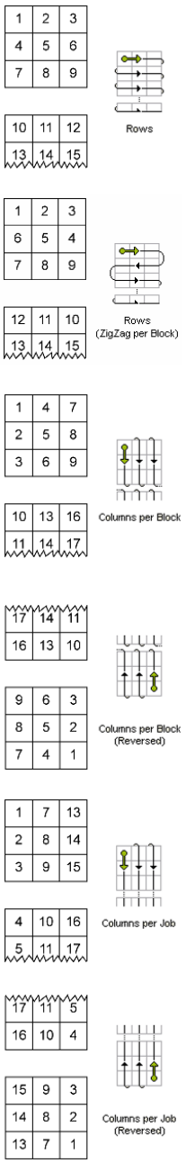
Filling Order
The following options are available:
•
Rows – the numbering pattern is restarted when end of a row is reached
and continues from the left cell of the next row. The starting position is the
top left cell of each block.
•
Rows (ZigZag per Block) – the numbering pattern alternates direction for
each row and is restarted once the beginning of a row is encountered. The
starting position is the top left cell of each block.
•
Columns per Block – the numbering pattern is restarted when the end of a
column in a block is reached and continues from the top cell of the next
column. The starting position is the top left cell of each block.
Note: If the Block Size is set to ‘Complete Job’, then this filling order is equal
to 'Columns per Job'.
•
Columns per Block (Reversed) – the numbering pattern is restarted when
the end of a column in a block is reached and continues from the bottom cell
of the next column. The starting position is the bottom right cell of each
block.
Note: If the Block Size is set to ‘Complete Job’, then this filling order is equal
to 'Columns per Job (Reversed)'.
•
Columns per Job – the numbering pattern is restarted when the last cell of
a column in the job is reached and continues from the top cell of the next column. The starting
position is the top left cell of the job.
•
Columns per Job (Reversed) – the numbering pattern is restarted when
the last cell of a column in the job is reached and continues from the bottom
cell of the next column. The starting position is the bottom right cell of the
job.
28 EN
Create Gaps
Some jobs need to be interrupted after a certain amount of labels. This amount can be defined using the
Block Size parameter. Gaps can be inserted between these blocks as well as to the beginning and to the end
of a job.
No one-ups are printed in the gap area, so the press operator can easily identify the gap as a white space.
However, all the elements outside the one-up area, such as die cut marks, are printed.
In this part of the dialog you can specify where you want the gaps to be generated. The following options
are available:
•
Starting gap – this gap will be printed first (with respect to the printing direction), before any variable
data are printed.
•
Gap between blocks – these gaps will be generated between Blocks.
Note: When Block Size is set to ‘Complete job’, this toggle is useless.
•
Ending gap – this gap will be printed last (with respect to the printing direction), after all the variable
data have been printed.
•
Gap Size –specifies the size of the gaps in grid rows, frames, meters or feet units.
Put Empty one-ups
In general, the database size is not an exact multiple of the number of cells within a block. At most cases, one
of the blocks cannot be filled completely with database entries. It will be padded with empty one-ups.
The toggles At the start or At the end specify where to put the empty one-ups with respect to the printing
direction.
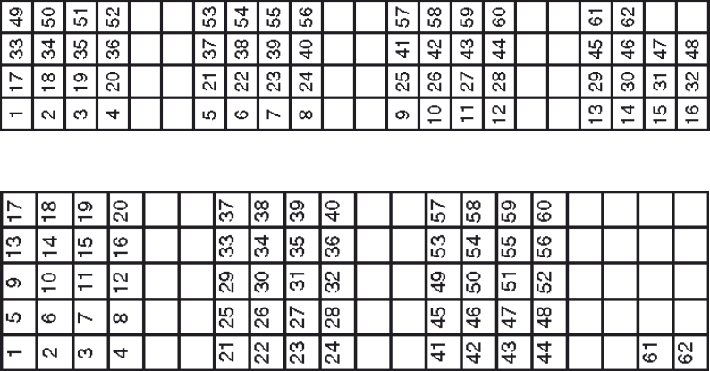
Examples
⇐
Printing direction
This job was created using the following settings: Block size: 4 grid rows; Filling order: Columns per Job; Gap
between blocks: 2 grid rows; Empty One-ups: At the end
This job was created using the following settings: Block size: 4 grid rows; Filling order: Columns per Block;
Gap between blocks: 2 grid rows; Empty One-ups: At the end
EN 29 DeskPack Workflow
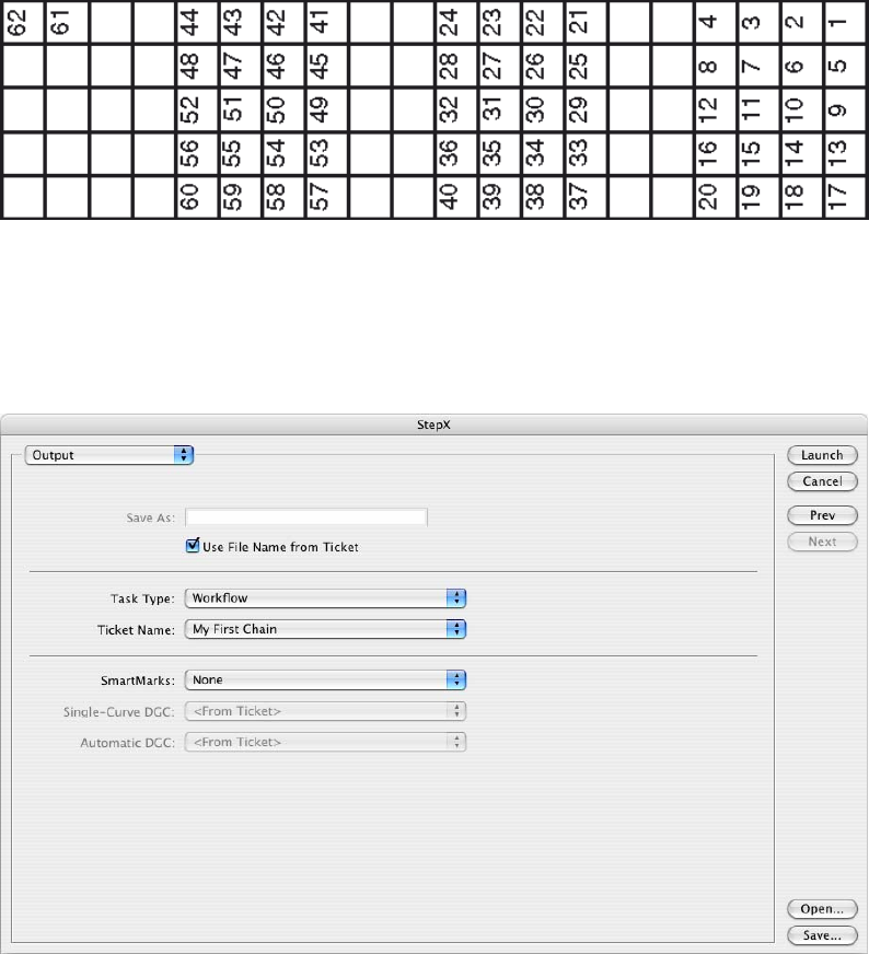
This job was created using the following settings: Block size: 4 grid rows; Filling order: Columns per Block
(Reversed); Gap between blocks: 2 grid rows; Empty One-ups: At the beginning
Launching Server Tasks
The last page of the StepX plug-in is used to launch server tasks, once all the repetitions and variable data
parameters are specified correctly. The layout of the last page depends on whether the variable data are or
are not used.
For Variable Data Printing, the output options have been slightly modified:
•
Task Type has only two options: 'Expand Variable Data to PPML File (DeskPack only)' and
'Workflow'. The list of tasks that can follow will contain only the global tasks and workflows that start
with the ticket 'Expand Variable Data to PPML File (DeskPack only)'. The tickets which were created
according to the chapter XXX (Prepare data) can be selected and run from here. The 'Expand
Variable Data to PPML File (DeskPack only)' task is used only if you care about the expansion output
but do not want to run the RIP task afterwards. In most cases, it is recommended to use a chained
ticket with a 'RIP to ws4000 Series' task.
•
The SmartMarks option allows the user to specify a Grid Mark set (created using PackEdge or
Plato), which results in generating appropriate die-cut marks in the design. You can contact us and
request a specific SmartMark set, based on your needs.
Once the configuration and all the parameters contained in StepX are specified correctly, launching the
appropriate workflow will result in expansion and ripping of the variable data, and placing the output JLT files
into the hotfolder on the press.
30 EN
Configuration
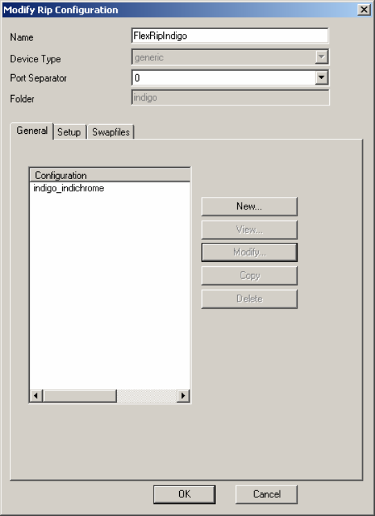
FlexRip/Indigo Configuration
To configure the RIP, a FlexRip/Indigo Dispatcher must exist. Usually a default one is created during the
installation process. To modify its settings, use the FlexRip Configurator application.
EN 31 Configuration
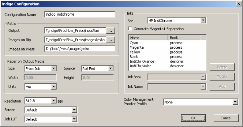
Dispatcher Configuration
The Paths area contains location of the Master JLT file and of all the variable JLT files (images). The output
folder of the RIP is the hotfolder on the press. Please note, that all of the paths must use the UNC format, with
the 'Images on Press' field being the only exception, since this path is used by the press to access the
variable JLT files stored at its local drive.
If your network drive is mapped to a drive letter, an automatic conversion to UNC format will be offered.
Typical paths look similar to this:
Output: \\indigo\Prodflow_Press\input\lan
Images on Rip: \\indigo\Prodflow_Press\images\esko
Images on Press: D:\Jobs\Press\images\esko
Access to the Press PC
The WorkFlow Manager user BGSYSTEM must have write access to the hotfolder of the press PC. If not,
the 'RIP to ws4000 Series' task will cause an error when writing the Master JLT to the hotfolder.
The configuration of access rights depends on the OS where the WorkFlow Manager runs:
•
Windows 2000 Server – make sure that you have access to the Administrator account of the press
PC. Create the user BGSYSTEM on the press PC with the same password as the one on the
WorkFlow Manager system and grant this user access to the required folders.
•
Windows 2003 Server
o
Log in as user BGSYSTEM on the WorkFlow Manager.
o
Map the hotfolder of the Press:
net use \\indigo\Prodflow_Press /SAVECRED
user: . . .
password: . . .
/SAVECRED stores the credentials permanently. During subsequent logons the share on the
press will be automatically accessible.
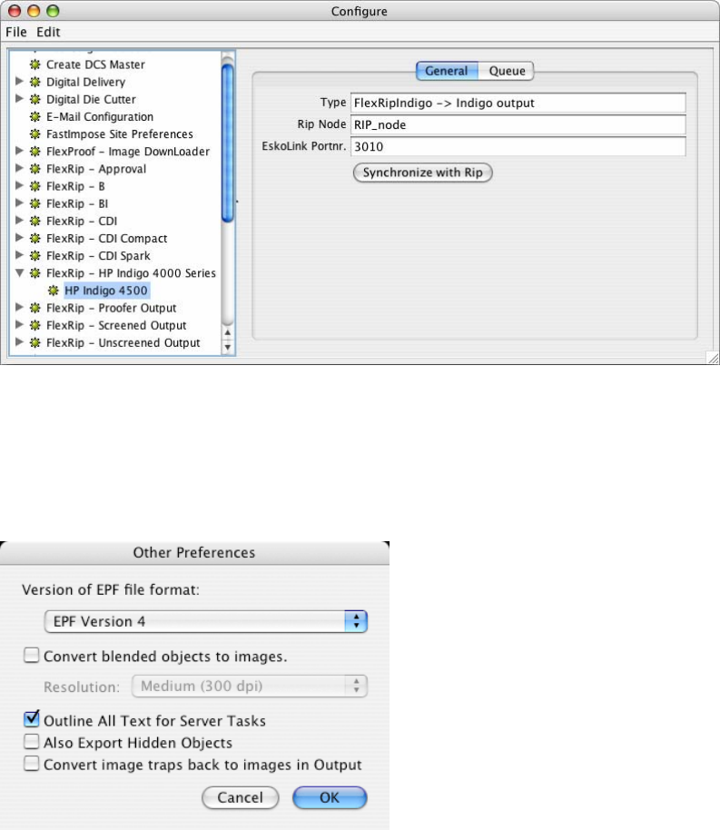
Dispatcher connection with the WorkFlow Manager
The WorkFlow Manager must be configured in order to be able to send data to the HP Indigo Dispatcher. A
new proofer device that is linked to the HP Indigo Dispatcher must be created. This can be done using the
Configure application (WorkFlow Manager Pilot > Tools menu > Configure).
In the left pane of the Configure application, select 'FlexRip – HP Indigo ws4000 Series' and click File > New
to create a new device. In the right pane, enter the port number of the Indigo Dispatcher and click
'Synchronize with Rip'.
32 EN
DeskPack Configuration
Make sure that EPF Export in Illustrator is configured to use EPF version 4.
This preference can be found in Illustrator CS2.
On Windows: Edit > Preferences > Esko > Server > Other Preferences…
On Mac: Illustrator > Preferences > Esko > Server > Other Preferences…
EN 33 Glossary
Glossary
B
Block Certain amount of continuously printed substrate.
WorkFlow Manager Pilot The client interface application of the WorkFlow Manager.
C
CMS Abbreviation of Color Management System.
Container Network share used by the WorkFlow Manager as storage.
F
Field Name Name of a database column.
File SmartName The same as a SmartName, but used specifically for files.
Frame Dimensions of the printout. Equal to sheet or spread.
G
Gap Certain amount of continuously printed substrate without one-ups.
Grid Stepped and repeated one-ups.
J
Jobfolder A folder placed within a Container managed by the WorkFlow Manager.
O
One-up Single graphical design prepared for printing process.
P
WorkFlow Manager Pilot The same as Esko WorkFlow Manager Client.
PackEdge The vector-based editor.
Plato The Step and Repeat editor.
S
SmartName A shortcut representing a value which is resolved under a certain condition.
V
VDP Abbreviation of Variable Data Printing.

reorder: P/N CA294-05780
Copyright © 2008 Hewlett-Packard Company
This is an HP Indigo digital print. Printed in Israel.
www.hp.com/go/indigo

reorder: P/N CA294-05780
Copyright © 2008 Hewlett-Packard Company
This is an HP Indigo digital print. Printed in Israel.
www.hp.com/go/indigo
