HP Z200, Z400 And Xw4000 Workstations Rack Mount Tray Installation C02027237
User Manual: HP HP Z200, Z400 and xw4000 Workstations - Rack Mount Tray Installation
Open the PDF directly: View PDF ![]() .
.
Page Count: 10

Rack mount tray installation
Introduction
This document describes how to install the HP Z200 and Z210, Z400, and xw4000 series
Workstations into a rack mount tray. It also describes how to mount the workstation-tray assembly into
a rack.
Kit contents
●Rack mount tray
●Adapter brackets
●Rails and mounting hardware (installation instructions in Appendix A of this document)
●Installation instructions
●Warranty information
Required tools
●T-15 Torx screwdriver
●T-20 Torx screwdriver
●Cross-tip screwdriver
© 2011 Hewlett-Packard Development Company, L.P. Printed in the U.S.
ENWW Introduction 1
Warnings and cautions
WARNING! Any surface or area of the equipment marked with this symbol indicates the
presence of an electrical shock hazard. To reduce the risk of injury from electrical shock, do not open
any enclosed area marked with this symbol.
WARNING! To reduce the risk of electric shock or damage to your equipment:
— Do not disable the power cord grounding plug. The grounding plug is an important safety feature.
— Plug the power cord in a grounded (earthed) outlet that is easily accessible at all times.
— Disconnect power from the equipment by unplugging the power cord from the electrical outlet.
WARNING! Any surface or area of the equipment marked with this symbol indicates the
presence of a hot surface or hot component. If this surface is contacted, the potential for injury exists.
To reduce the risk of injury from a hot component, enable the surface to cool before touching.
WARNING! If a product is shipped in packaging marked with this symbol, , the product must
always be lifted by two persons to avoid personal injury due to product weight.
WARNING! To reduce the risk of serious injury, read the Safety and Comfort Guide. It describes
proper workstation setup, posture, health, and work habits for computer users, and provides important
electrical and mechanical safety information. This guide is located at http://www.hp.com/ergo and on
the documentation CD (if one is included with the product).
CAUTION: Static electricity can damage the electronic components of the workstation. Before
beginning these procedures, be sure you discharge static electricity by briefly touching a grounded
metal object.
CAUTION: To prevent damage to the workstation, observe the following Electrostatic Discharge
(ESD) precautions while performing the system parts removal and replacement procedures:
— Work on a static-free mat.
— Wear a static strap to ensure that any accumulated electrostatic charge is discharged from your
body to the ground.
— Create a common ground for the equipment you are working on by connecting the static-free mat,
static strap, and peripheral units to that piece of equipment.
NOTE: HP accessories are for use in HP Workstation products. They have been extensively tested for
reliability and are manufactured to high quality standards.
2 Rack mount tray installation ENWW
Step 1—Preparing the workstation
NOTE: All illustrations are examples only. Workstation models vary. For product-specific information,
see the service guide for your HP workstation at http://www.hp.com/support/manuals before
beginning installation.
To prepare the workstation for component installation:
1. Power down the workstation, and then disconnect the power cord.
2. Power down all external devices, and then disconnect them from the workstation.
Step 2—Mounting the rails to the rack
1. Attach the rails to the rack. See Appendix A for installation instructions.
2. If glide strips were not factory-installed, then apply them to the rail shelf.
a. Remove the adhesive backing from the back of the glide strips.
b. Apply a glide strip to the top surface of each rail.
Figure 1 Applying glide strips
ENWW Step 1—Preparing the workstation 3
Step 3—Attaching the rack mount tray to the
workstation
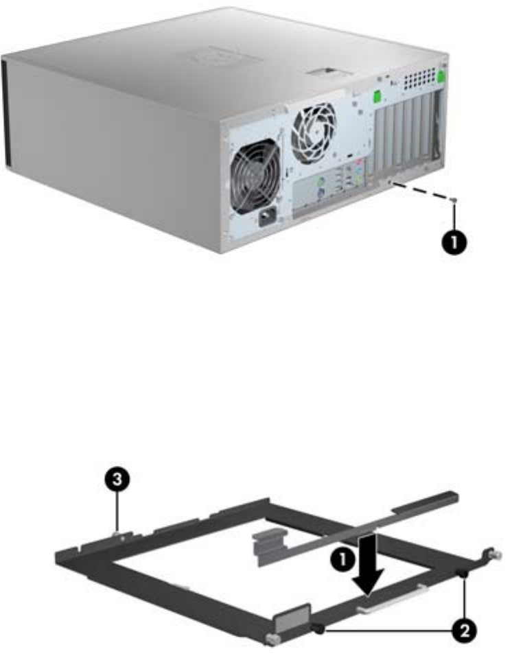
1. Using a T-15 Torx screwdriver, remove the indicated chassis screw (1), if present, from the rear of
the workstation. Some workstation models do not use the chassis screw as shown.
Figure 2 Removing the chassis screws
2. To prepare the tray:
a. Select the adapter bracket with the label that matches your workstation model.
b. To install the adapter bracket onto the tray, fit the tab (1) on the adapter bracket into the
locking hole on the tray, and then secure the two black captive screws (2).
c. Loosen the black rear captive screw (3). This will be used to secure the rear of the
workstation, once seated in the tray.
Figure 3 Installing the adapter bracket on the tray
4 Rack mount tray installation ENWW
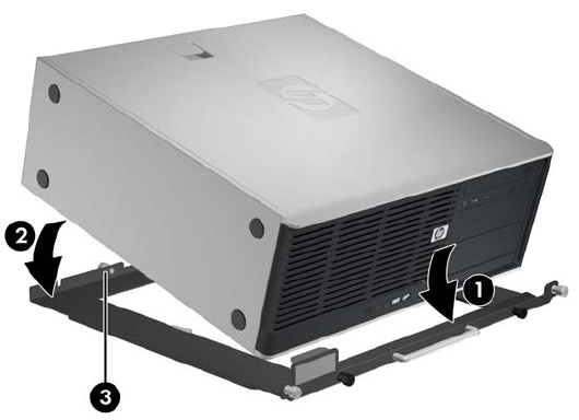
3. To install the workstation on the tray:
a. Guide the front bezel of the workstation under the lip of the adapter bracket (1).
b. Rotate the back of the workstation down onto the tray (2).
c. Tighten the single, black rear captive screw (3), to secure the rear of the workstation into the
tray.
Figure 4 Installing the workstation on the tray
Step 4—Loading the workstation-tray assembly into
the rack
To load the assembly into the rack:
1. Place the rear of the workstation-tray assembly on the rail-bracket shelf (1).
ENWW Step 4—Loading the workstation-tray assembly into the rack 5
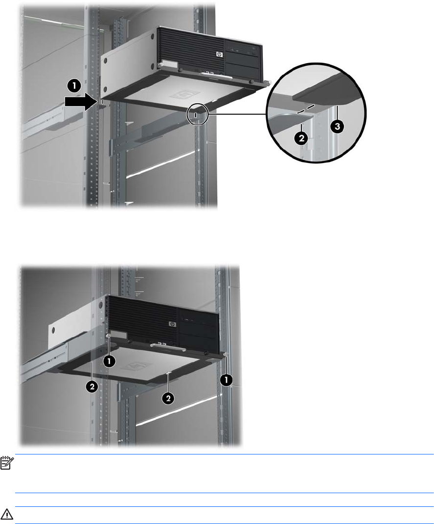
2. Ensuring that the rail-bracket shelf (2) is engaged by the lip on the underside of the tray (3), slide
the assembly into position in the rack.
Figure 5 Loading the workstation into the rack
3. Secure the assembly into the rack by tightening the silver captive screws (1).
Figure 6 Completing installation
NOTE: To remove the assembly from the rack, loosen the silver captive screws (1), and then pull
the handle to slide the assembly out of the rack until the latches in the tray (2) engage the stop
feature. Reach under the assembly and release the latches (2) to disengage the tray from the rails.
CAUTION: For removal, the workstation must be supported once the latches are disengaged.
6 Rack mount tray installation ENWW
Step 5—Completing installation
1. Reconnect power to the workstation.
2. Restore power to the workstation.
ENWW Step 5—Completing installation 7

A HP Depth-Adjustable Fixed Rails
Rack Option Kit installation
instructions
Introduction
The HP Depth-Adjustable Fixed Rails Rack Option Kit allows the user to install depth-adjustable fixed
rails in racks from 19 inches (48.26 cm) to 31 inches (78.74 cm) in depth. Once installed, these depth-
adjustable fixed rails can be used to support a variety of rack-mountable devices.
This option occupies 2U of HP rack space and can be used with all HP Series racks.
NOTE: A Rack Unit (U) is defined as 1.75 inches (4.445 cm).
Kit contents
The items and quantities required for installation include:
●Depth-adjustable fixed rail (1 left, 1 right)
●Wing nut (4)—included with rail assemblies
●Cage nut (4)
●Installation instructions (this document)
This kit may contain extra pieces of hardware for your convenience.
Required tools
●Medium cross-tip screwdriver
8 Appendix A HP Depth-Adjustable Fixed Rails Rack Option Kit installation instructions ENWW
Rack considerations
Before beginning these procedures, be sure you understand and follow these precautions:
WARNING! To reduce the risk of personal injury or damage to the equipment be sure that:
● The leveling jacks are extended to the floor.
● The full weight of the rack rests on the leveling jacks.
● The stabilizing feet are attached to the rack if it is a single-rack installation.
● The racks are coupled in multiple-rack installations.
● Only one component is extended at a time. A rack may become unstable if more than one
component is extended for any reason.
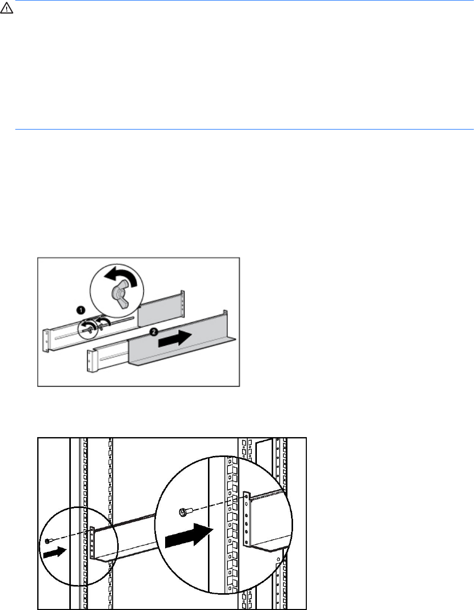
Installing the depth-adjustable fixed rails rack
option kit
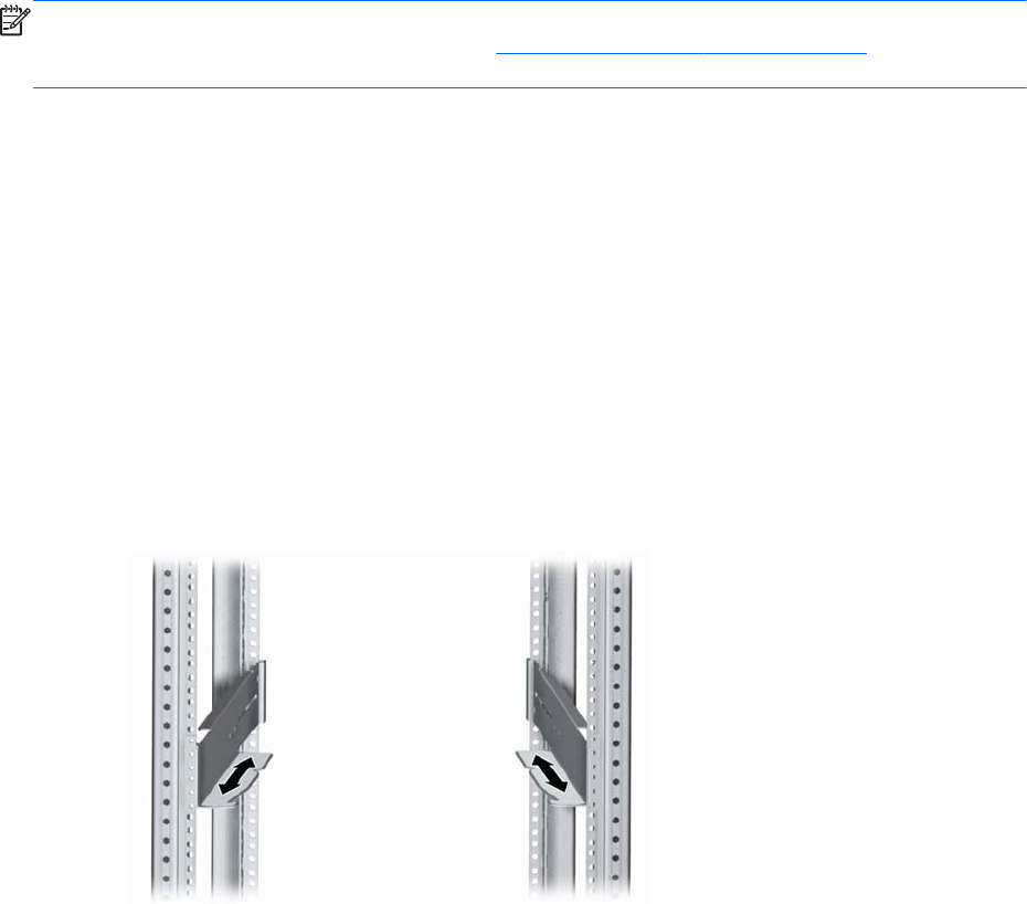
1. Loosen the wing nuts (1) and extend the brackets to the desired length (2) for each depth-
adjustable fixed rail.
2. Tighten the wing nuts slightly to stabilize the brackets during installation.
3. Beginning at the front of the rack, use the top screw holes for initial placement of the depth-
adjustable fixed rails. These screws may have to be moved later to correctly install the component.
ENWW Rack considerations 9
4. Install cage nuts into the rear locations of the rack that best align with the bottom two holes at the
rear of the depth-adjustable fixed rail, ensuring they are installed level with the front.
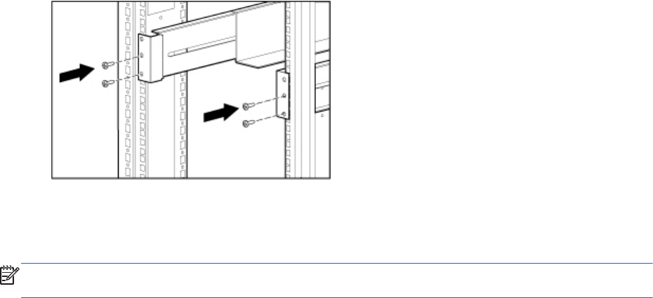
5. Insert two screws through each depth-adjustable fixed rail and into the cage nuts installed earlier,
securing the rail to the rear of the rack.
6. Retighten the wing nuts on the depth-adjustable fixed rails.
The rails are now ready for component installation. Refer to the documentation included with the
component for complete installation instructions.
NOTE: After installing the component, insert additional screws into the front depth-adjustable fixed
rails for component support.
10 Appendix A HP Depth-Adjustable Fixed Rails Rack Option Kit installation instructions ENWW
