HUAC C27G-CPAL-AB-C Quint Band Signal Booster User Manual Rev3
SHENZHEN HUAPTEC CO., LTD Quint Band Signal Booster Users Manual Rev3
HUAC >
Users Manual Rev3

Consumersignalbooster
usermanual
Content
Whatisincluded............................................................................4
1HOWITWORKS.....................................................................................4
2TOOLREQUIRED....................................................................................4
3HOWTOINSTALLYOURNEWCELLULARBOOSTER(forVehicle
installations)................................................................................................5
3.1Outsideantenna:.........................................................................5
3.2Wirelessvehicleinstallations:......................................................5
3.3Insideantenna:............................................................................6
3.4Feeder..........................................................................................6
3.5Powersupply................................................................................6
3.6Installnote:..................................................................................6
4HOWTOINSTALLYOURNEWCELLULARBOOSTER(forFixed
Installations)................................................................................................7
4.1Overview......................................................................................7
4.2Planthelayoutofyoursystem....................................................9
4.3CheckforSignalStrength.............................................................9
4.4Runcoaxialcable.......................................................................10
4.5InstalltheDonor(Outdoor)antenna........................................11
4.6InstalltheServer(Indoor)antenna..........................................11
4.7Installyourcellularbooster......................................................12
4.8Powerupyourcellularbooster................................................12
4.9ChecktheCellularBoosterStatus.............................................13
5UNDERSTANDTHEPORTS,MGCDIPSWITCH,LEDSTATUS...............14
5.1Repeaterports..........................................................................14
5.2LEDstatus..................................................................................14
5.3Deviceconnect..........................................................................15
6AuthorizedKittingOptions................................................................16
6.1Donor(Outdoor)defaultantennaforvehicleinstallations......16
6.2Donor(Outdoor)antennaforfixedinstallations......................17
6.3Server(Indoor)defaultantennaforvehicleinstallations.........17
6.4Server(Indoor)antennaforfixedinstallations.........................18
6.5AntennaKittingOptionsforvehicleinstallations.....................18
OutdoordefaultAntenna&CableKitOptions................................18
IndoordefaultAntenna&CableKitOptions...................................18
6.6AntennaKittingOptionsforfixedinstallations.........................18
OutdoorAntenna&CableKitOptions............................................18
IndoorAntenna&CableKitOptions...............................................19
7TROUBLESHOOTING...........................................................................20
8FREQUENTLYASKEDQUESTIONS.......................................................22
9FCCRFExposureStatement...............................................................24
10Warning...........................................................................................24
11Specification....................................................................................25
WHATISINCLUDED
1. BoosterC27G‐CPAL‐AB‐C
2. OutdoorMagnetMount5dbiWhipAntenna
3. IndoorStickerMountPanel3dbiMobileAntenna
4. DCPowerAdapter
1 HOWITWORKS
Thecellularboosterprovidesreliabletwo‐waycellularcoverageby
improvingsignalstrengthinhomes,buildings,offices,andotherareas
wherecellularreceptionisweakorunreliable.
Thesystemamplifiesthesignalfromthenearestcellulartowerand
retransmitsatahigherpowerlevelwithinalocalarea.
Thismanualprovidessimpleinstallationinstructionsthatwillhaveyour
cellularboosterkitrunninginrecordtime.
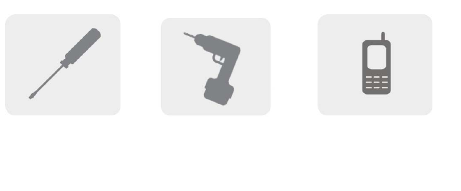
2 TOOLREQUIRED
PhillipsScrewdriver Drill Cellular Phone (to chec
k
signalstrength)
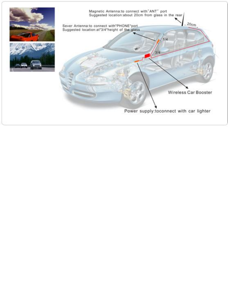
3 HOWTOINSTALLYOURNEWCELLULAR
BOOSTER(forVehicleinstallations)
3.1 Outsideantenna:
Adopt the car magnetic antenna or chuch antenna.
Function: receive the signal from the base station, through
the feeder to booster. Meanwhile transmit back the signal to
the base station after enlarge the signal.
3.2 Wirelessvehicleinstallations:
Generally, hidden inside the corner nearby the power
supply
Function: two-way, full-duplex amplifier the inside &outside
signal of the car, and the maximum uplink is to 2W.

3.3 Insideantenna:
Adopt the car magnetic antenna or chuch antenna.
Function: Transmit the enlarger signals to the mobile phone,
and receive the uplink car phone signal to booster.
3.4 Feeder
When install, hide it in the decoration materials or pads.
Function: Connect the feeder, antenna, and mobile phone
seat.
3.5 Powersupply
Adopt the9V-12V power supply, and it is extremely
convenient for direct feed by the car power, also we support
the car charger.
3.6 Installnote:
When install, try to separate the inside &outside antenna to the max
straight distance, and make the inside and outside antenna could
not mutual see (also don't mutual see each other through the roof
skylight)
4 HOWTOINSTALLYOURNEWCELLULAR
BOOSTER(forFixedInstallations)
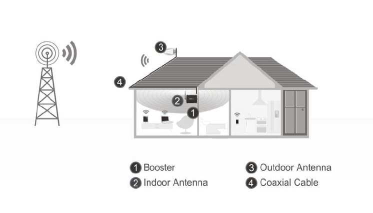
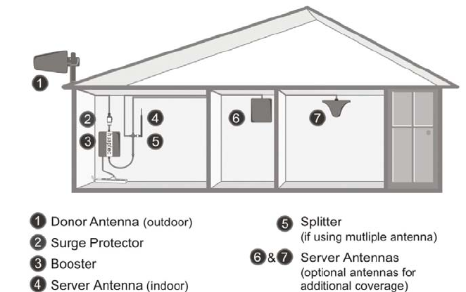
4.1 Overview
Thisguidewillhelpyouproperlyinstallyourcellularboosterkit.Itis
importanttoreadthroughalloftheinstallationstepsbeforeinstalling
yourequipment.Thoroughlyreadthroughtheinstructions,visualize
wherealltheequipmentwillneedtobeinstalledanddoasoft
installationbeforemountinganyequipment.
1
•BOOSTER– selectlocation
•Installtheboosterinanareathatisprotectedfromtheweather,properly
ventilatedandisawayfromexcessiveheatandmoisture.
2
•DONORANTENNA(OUTDOOR)‐selectlocation
•Mountthesignal(outdoor)antennainanelevatedoutdoorlocationso
thatitpointstowardsthecellulartowerandawayfromwheretheinside
antennawillbelocated.
3
•OUTDOORCOAXIALCABLE‐ selectlocation
•Theoutdoorcoaxialcableisusedtoconnectthedonor (outdoor)antenna
tothebooster.
4
•INDOORCOAXIALCABLE‐(ifused)
•Theindoorcoaxialcableisusedtoconnecttheserver(indoor)antennato
thebooster.
5
•SERVERANTENNA(indoor)
•Theideallocationforthedistributionantennawillbetheareaofyour
propertywhereyouneedtoimprovethesignalmost.
•NOTE:Thesignalstrengthwillbestrongestclosesttotheantenna.
•IMPORTANT:Thesignalantenna(outdoor)shouldalwaysbeseparatedfromthe
distributionantenna(indoor)byatleast20verticalfeetincludingtheseparationof
athickbarriersuchasarooforawall.Dependingonthestrengthofyouroutdoor
signal,theweakerthesignalthelessseparationdistanceisrequired.
7
•LIGHTNINGSURGEPROTECTOR‐(SOLDSEPARATELY)
•Thelightningsurgeprotectorconnectsinbetweenthesignalantennaandthe
booster.
•IMPORTANT:Lightningsurgeprotectormustbegrounded.
8• COMMISSIONINGTHESYSTEM
!
4.2 Planthelayoutofyoursystem
Beforeyougetstartedyouwillneedtoplanthelayoutofyoursystem.
Thisinvolvescheckingsignalstrengthforsignalscomingfromthecellular
tower,aswellasantenna,boosterandcableplacement.
4.3 CheckforSignalStrength
Selectalocationontheroofofthebuildingtoinstallthesignalantenna,
bymonitoringyourcellularphone’ssignalstrength(signalbars)tofind
thestrongestsignalfromyourcarrier’scellulartower.
MarkthatareaastheinstallationlocationfortheDonor(outdoor)
IMPORTANT:Confirmthatyouhaveatleast20feetofverticaldistance
betweenthemarkedantennalocationandthelocationwhereyouwill
placetheServer(indoor)antenna.Topreventthesystemfromoscillation
(feedback)youwanttoensurethatthereisenoughseparationbetween
thedistributionandsignalantennaorthattheyareshieldedfromeach
othertoensurethedistributionantennadoesnotsendasignalbackinto
thesignalantenna.Ifyoucannotachievetheseseparations,either
chooseanalternatelocationforthedonor(outdoor)antennaor
determineiftherearenaturalbarriersinthebuildingconstructionitself
thatwillattenuatesignalsbetweenthetwoantennassothatoscillation
canbeprevented.
4.4 Runcoaxialcable
Looselyrunthecoaxialcablefromyouroutdoorantennatoyourbooster.
(Afteryouhavetestedthesystemyoucanpermanentlysecurethe
coaxialcable).
Asyourouteandpullcabling,followthesegeneralguidelines:
Bendcablesandroutethemsmoothly,andprotecttheouterskin
againstanydamage.
Keephorizontalcablesstraightandfastenthemwithatieeverythree
tofivefeet.
Bindandfastenverticalcableseverysixtoeightfeet.
Waterproofalloutdoorconnectionswithsiliconecaulking
Becarefulwhenpluggingtheconnectorinsoasnottodamagethe
centerpinsontheconnectors.
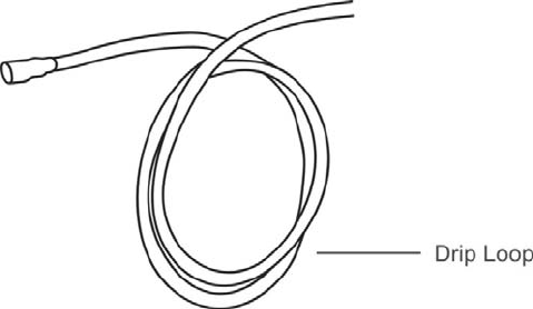
4.5 InstalltheDonor(Outdoor)antenna
Connectthesuppliedcoaxialcabletotheantenna.Werecommend
applyingsiliconecaulkingtofullywaterprooftheconnection.
Attachthecableinsuchawaythatadriploopisformed.
Oncemounted,connectoneendofthecoaxialcabletothedonor
(outdoor)antennaandtheotherendtothecellularboosterwhereitis
marked“outdoor”
4.6 InstalltheServer(Indoor)antenna
Connectoneendofthecoaxialcabletotheantennaandtheotherend
tothecellularboosterwhereitismarked“indoor”.
Selecttheinstallationlocationofyoursuppliedserver(outdoor)antenna
basedonthefollowing:
OmniCeilingdirectionalantenna
Placeinthecenteroftheareawherethesignalneedstobeamplified.
Paneldirectionalantenna
Placeintheouterperimeteroftheareathesignalneedstobeamplified.
WhipOmnidirectionalantenna
Mountdirectlytotheconnectormarked“indoor”onthecellularbooster.
4.7 Installyourcellularbooster
Installthecellularboosterinalocationthatisproperlyventilatedand
notexposedtoexcessiveheat,moistureand/ordirectsunlight.The
optimalareawouldbeonawalllocatednearapoweroutlet.
Itshouldbemountedinaneasilyaccessibleareasoit’seasytoperform
generalmaintenancewiththecoaxialcableconnections,dipswitch
settingsandpoweradaptor.
Makesureallcablesandantennasaresecurelyconnectedbefore
commissioningthesystem.
4.8 Powerupyourcellularbooster
OncealltheFollowingprecautionshavebeentaken,poweronthe
cellularbooster.
1. Verifythatyouhaveleftatleast20feetofverticalseparationspacebetweenthe
indoorandoutdoorantennas.
2. Neverpointthefrontofthedonor(outdoor)antennatowardstheinsideofthe
server(outdoor)antenna.
3. Verifythatthesuppliedcoaxialcablesfromboththedonor(outdoor)antenna
andtheserver(outdoor)antennaareproperlyconnectedtothecellularbooster
beforepoweringitup.
4. Carefullypluginthesuppliedpoweradaptorintothebackofthecellularbooster
whereitismarked‘power’andconnecttheotherendtoapoweroutlet.
TheLEDindicatormarkedpowershouldlightupgreen.
4.9 ChecktheCellularBoosterStatus
Yourcellularboostercomesequippedwithelectronicsensorsdesigned
toidentifycellularsignaloverloadoroscillationwhichcanhindersignal
boostingperformance.Yourcellularboosterisspeciallydesignedto
automaticallydecreasegaintocompensateforthesecircumstances.The
devicealsohasafeaturetoautomaticallyshutdownincaseofexcessive
oscillation.Improperequipmentinstallationandunusablesignalquality
cancauseoscillation,thisiswhyitisimportanttofullyunderstandthe
LEDalarmlightsonyourbooster,astheywillhelpyouidentifyandsolve
anypotentialissues.
ThecoloroftheLEDindicatesthestatusoftheboostersystem.
5 UNDERSTANDTHEPORTS,MGCDIP
SWITCH,LEDSTATUS
5.1 Repeaterports
1) Outdoor port: connected with the donor antenna by cable.
2) Indoor port: connected with server antenna directly or by cable.
3) DC IN: connected with power supply.
5.2 LEDstatus
1. StatusanddefinitionofPOWERindicators:
Status Definition
Green Normal
Off DC power problem
2. StatusandDefinitionofALARMindicators;AlarmLEDonlyworksfor
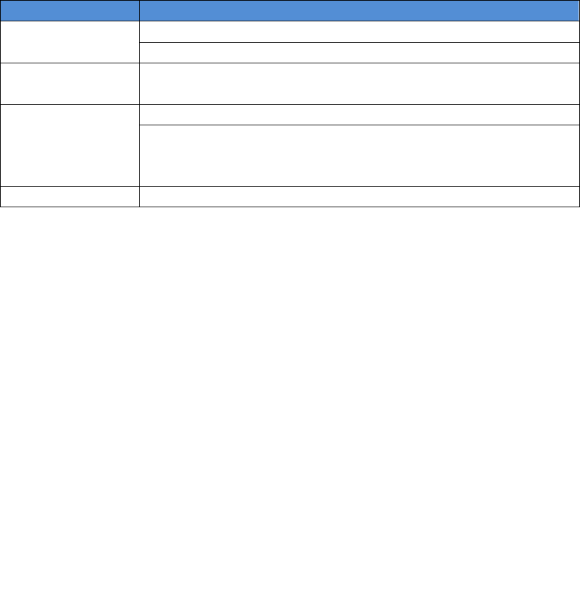
downlinksignals
Status ALARM
Green It is working in linearity
attention: Input signals may be not enough
Red There are overloading or self-oscillation, strong input signals,
measures shall be taken
Orange
It is working in linearity
Attention: Please adjust MGC to increase the attenuation value, till you
find the “edge point” (I.E. the Alarm LED shall stay at green color, with
intention of turning Orange), and let the repeater work at this point.
Off Repeater break down
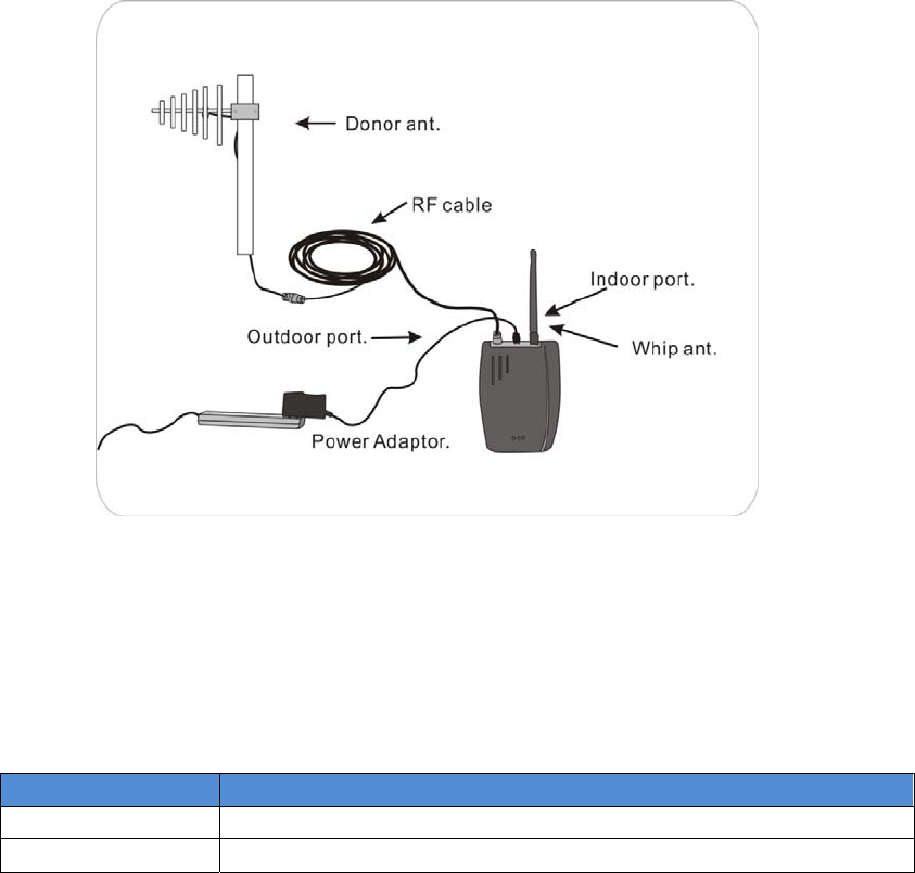
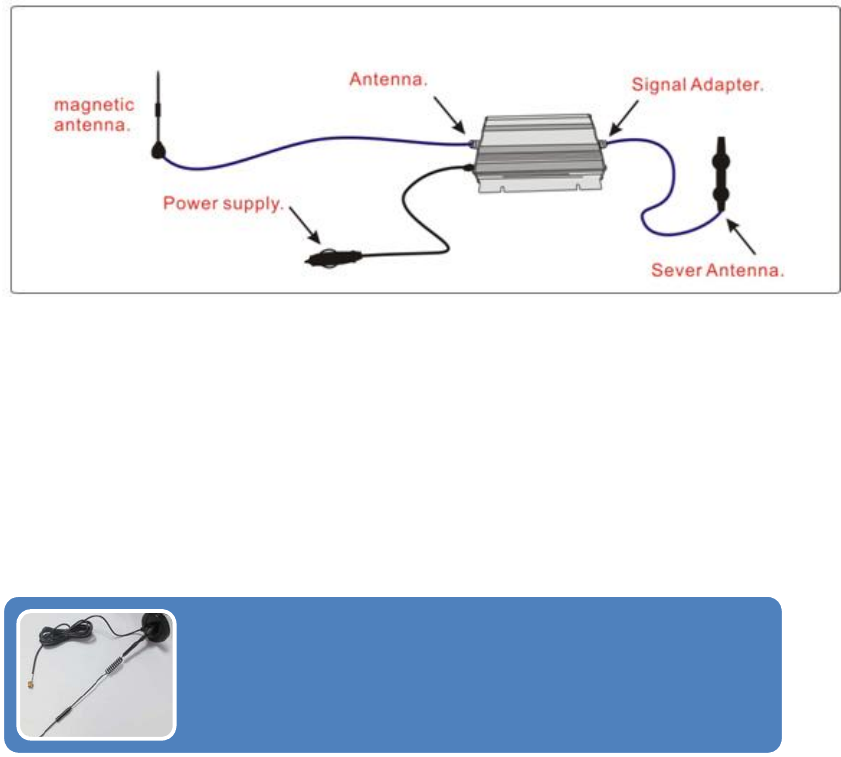
5.3 Deviceconnect
Required connection as shown in below figure:
1. Connect the magnet Antenna SMA male to the SMA
female with booster.
2. Plug the smaller one of the car booster into the socket
with DC, and another connect to the car power supply.
3. Connect the chuch antenna SMA male to the SMA
female of the adapter which marked “Signal Adapter”.
6 AuthorizedKittingOptions
6.1 Donor(Outdoor)defaultantennaforvehicle
installations
TheMagnetMountWhipAntenna
Thewhipantennaisanomni‐directionalantennawitha
360degreereach.Itisdesignedtodistributethesignal
fromthecenteroftheaffectedarea.Typicallyitis
connecteddirectlytothebooster.
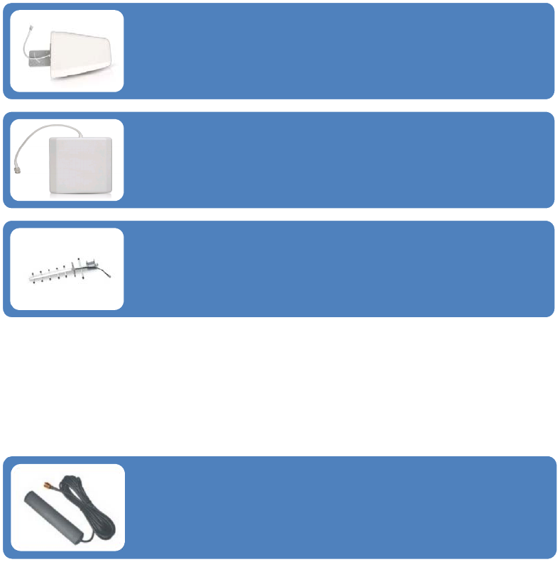
6.2 Donor(Outdoor)antennaforfixedinstallations
6.3 Server(Indoor)defaultantennaforvehicle
installations
TheYagiLpdaAntenna
Theyagiisaveryprecisedirectionalantennawithapowerfulreach.This
antennashouldbeinstalledinanelevatedpositionandmustbepointed
towardsyourcarrier’scellulartower.
NOTE:Thisantennaisnotmeanttocapturesignalfrommultiplecarriers.
ThePanelAntenna
Thepanelisadirectionalantennawitha120degreereachandisdesignedto
capturethesignalfrommultiplecarriertowers.Thisantennashouldbe
installedinanelevatedpositionandmustbepointedtowardsyourcarrier’s
cellulartowers.
YagiAntenna
Theyagiisaveryprecisedirectionalantennawithapowerfulreach.This
antennashouldbeinstalledinanelevatedpositionandmustbepointed
towardsyourcarrier’scellulartower.
NOTE:Thisantennacanonlysupportsinglebandsignalbooster.
TheStickerMountPanelMobileAntenna
Themobileantennaisanomni‐directionalantennawitha360
degreereach.Itisdesignedtodistributethesignalfromthe
centeroftheaffectedarea.Itisconnecteddirectlytothe
booster.
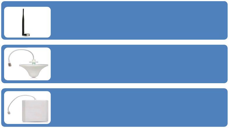
6.4 Server(Indoor)antennaforfixedinstallations
6.5 AntennaKittingOptionsforvehicleinstallations
OutdoordefaultAntenna&CableKitOptions
1. Kit66‐295‐0
OutdoorMagnetMount5dbiWhipAntenna
IndoordefaultAntenna&CableKitOptions
1. Kit3‐0
IndoorStickerMountPanel3dbiMobileAntenna
6.6 AntennaKittingOptionsforfixedinstallations
OutdoorAntenna&CableKitOptions
1. Kit11‐5050
OutdoorYagi11dbiAntenna&50’5DCoaxialCable&SMAmaletoNfemaleAdapter
2. Kit10‐50400
OutdoorPanel10dbiAntenna&50’400CoaxialCable&SMAmaletoNfemaleAdapter
3. Kit10‐7550
OutdoorPanel10dbiAntenna&75’5DCoaxialCable&SMAmaletoNfemaleAdapter
4. Kit10‐10050
OutdoorPanel10dbiAntenna&100’5DCoaxialCable&SMAmaletoNfemaleAdapter
5. Kit9‐5050
OutdoorYagi9dbiAntenna&30’5DCoaxialCable&SMAmaletoNfemaleAdapter
6. Kit9‐75400
OutdoorYagi9dbiAntenna&75’400CoaxialCable&SMAmaletoNfemaleAdapter
TheWhipAntenna
Thewhipantennaisanomni‐directionalantennawitha360degreereach.It
isdesignedtodistributethesignalfromthecenteroftheaffectedarea.
Typicallyitisconnecteddirectlytothebooster.
TheOmniAntenna
Theomniantennaisanomni‐directionalantennawitha360degreereach.It
isdesignedtodistributethesignalfromthecenteroftheaffectedarea.
Typicallyitisinstalledinafalseordroppedceiling.
ThePanelAntenna
Thepanelisadirectionalantennawitha120degreereachandisdesignedto
distributethesignalfromaperimeterwallorceiling.
7. Kit9‐100400
OutdoorYagi9dbiAntenna&100’400CoaxialCable&SMAmaletoNfemaleAdapter
8. Kit9‐7550
OutdoorYagi9dbiAntenna&75’5DCoaxialCable&SMAmaletoNfemaleAdapter
9. Kit9‐10050
OutdoorYagi9dbiAntenna&100’5DCoaxialCable&SMAmaletoNfemaleAdapter
10. Kit5‐30400
OutdoorOmni5dbiAntenna&30’400CoaxialCable&SMAmaletoNfemaleAdapter
11. Kit5‐3050
OutdoorOmni5dbiAntenna&30’5DCoaxialCable&SMAmaletoNfemaleAdapter
12. Kit5‐50400
OutdoorOmni5dbiAntenna&50’400CoaxialCable&SMAmaletoNfemaleAdapter
13. Kit5‐5050
OutdoorOmni5dbiAntenna&50’5DCoaxialCable&SMAmaletoNfemaleAdapter
14. Kit5‐70400
OutdoorOmni5dbiAntenna&70’400CoaxialCable&SMAmaletoNfemaleAdapter
15. Kit5‐100400
OutdoorOmni5dbiAntenna&100’400CoaxialCable&SMAmaletoNfemaleAdapter
16. Kit5‐7550
OutdoorOmni5dbiAntenna&75’50CoaxialCable&SMAmaletoNfemaleAdapter
17. Kit5‐10050
OutdoorOmni5dbiAntenna&100’5DCoaxialCable&SMAmaletoNfemaleAdapter
IndoorAntenna&CableKitOptions
1. Kit5‐0
IndoorWhip5dbiAntenna
2. Kit100‐1550
IndoorPanel10dbiAntenna&15'5DCoaxialCable&SMAmaletoNfemaleAdapter
3. Kit100‐30400
IndoorPanel10dbiAntenna&30’400CoaxialCable&SMAmaletoNfemaleAdapter
4. Kit100‐5050
IndoorPanel10dbiAntenna&50’5DCoaxialCable&SMAmaletoNfemaleAdapter
5. Kit100‐7550
IndoorPanel10dbiAntenna&75’5DCoaxialCable&SMAmaletoNfemaleAdapter
6. Kit102‐7550‐50
2IndoorPanel10dbiAntennas&75’5DCoaxialCable&SMAmaletoNfemaleAdapter&a50
Ohm2‐waysSplitter
7. Kit103‐7550‐75
3IndoorPanel10dbiAntennas&75’5DCoaxialCable&SMAmaletoNfemaleAdapter&a75
Ohm3‐waysSplitter
8. Kit104‐7550‐50
4IndoorPanel10dbiAntennas&75’5DCoaxialCable&SMAmaletoNfemaleAdapter&three50
Ohm2‐waysSplitters
9. Kit100‐10050
IndoorPanel10dbiAntenna&100’5DCoaxialCable&SMAmaletoNfemaleAdapter
10. Kit100‐30400
IndoorPanel10dbiAntenna&100’400CoaxialCable&SMAmaletoNfemaleAdapter
11. Kit100‐50400
IndoorPanel10dbiAntenna&50’400CoaxialCable&SMAmaletoNfemaleAdapter
12. Kit100‐75400
IndoorPanel10dbiAntenna&75’400CoaxialCable&SMAmaletoNfemaleAdapter
13. Kit3‐0350
IndoorOmni3dbiAntenna&3’5DCoaxialCable&SMAmaletoNfemaleAdapter
14. Kit3‐1550
IndoorOmni3dbiAntenna&15’5DCoaxialCable&SMAmaletoNfemaleAdapter
15. Kit3‐30400
IndoorOmni3dbiAntenna&30’400CoaxialCable&SMAmaletoNfemaleAdapter
16. Kit3‐5050
IndoorOmni3dbiAntenna&50’5DCoaxialCable&SMAmaletoNfemaleAdapter
17. Kit3‐7550
IndoorOmni3dbiAntenna&75’5DCoaxialCable&SMAmaletoNfemaleAdapter
18. Kit3‐10050
IndoorOmni3dbiAntenna&100’5DCoaxialCable&SMAmaletoNfemaleAdapter
19. Kit3‐30400
IndoorOmni3dbiAntenna&30’400CoaxialCable&SMAmaletoNfemaleAdapter
20. Kit3‐50400
IndoorOmni3dbiAntenna&50’400CoaxialCable&SMAmaletoNfemaleAdapter
21. Kit3‐75400
IndoorOmni3dbiAntenna&75’400CoaxialCable&SMAmaletoNfemaleAdapter
22. Kit3‐100400
IndoorOmni3dbiAntenna&100’400CoaxialCable&SMAmaletoNfemaleAdapter
23. Kit32‐50400‐50
2IndoorOmni3dbiAntennas&50’400CoaxialCable&SMAmaletoNfemaleAdapter&a50
Ohm2‐waysSplitter
24. Kit33‐50400‐75
3IndoorOmni3dbiAntennas&50’400CoaxialCable&SMAmaletoNfemaleAdapter&a75
Ohm3‐waysSplitter
25. Kit34‐50400‐50
4IndoorOmni3dbiAntennas&50’400CoaxialCable&SMAmaletoNfemaleAdapter&three50
Ohm2‐waysSplitters
7 TROUBLESHOOTING
TheLEDalarmlightsrepresentthestatusoftheboosteroneach
frequency.Whenthelightsaregreenthedeviceisoperatingnormally
meaningthatitisnotexperiencinganyoscillation(feedback)anditis
boostingthesignalatmaximumpower.WhentheLEDlightsbeginto
changecolorfromgreentoorangetored,itmeansthatparticular
frequencyisexperiencingsomeoscillation(feedback).
Iftheoscillationisexcessivetheboosterwillshutdownforthat
particularfrequency.Theboosterwillstillworkfortheotherfrequency
onamulti‐bandbooster.

Oscillationiscausedwhentheindoor(distribution)antennasendsa
signalbackintotheoutdoor(signal)antenna.SimilartoaPAsystem,
whenthemicrophonegetstooclosetothespeakeritcausesfeedback.
Thiswilloccurifyourantennasaretooclosetogether,ortheindoor
antennaispointedattheoutdoorantenna.Makesureyouhave
adequateseparationandsometypeofshieldingbetweentheantennas
(Usuallyyourrooforacementwallisgoodenough).
IMPORTANTNOTES
The2mostimportantthingstolookforwhensettingupyoursystemis:
Bycapturingthebestinputsignalyouwillbeabletoenjoythemaximum
coverageandbestqualitysignalinsidewhereyourIndoorantennasare
located.Thebettertheinputsignal,thebettertheoutputsignal.Inorder
tofindthebestinputsignal,youwanttoplaceyouroutdoorantennaas
highaspossiblewiththeleastamountofobstructionbetweenthe
antennaandthecellularbasetower.Aclearlineofsiteisideal.
Isolatingthesignalfromtheantennasisdonebyensuringthatthe
Agoodinputsignal(thebestyoucanfind)
Isolatingtheoutdoor(donor)antennafromtheindoor
(server)antennassotheydonotfeedbackintoeach
other.

antennasarenotpointingtoeachotherandbyhavingenoughdistance
orbarriershieldinginbetweenthem.Thesignalstravellikeraysof
sunlight,adirectionalantennawillsendthesignalinthedirectionthatit
ispointing.Anomnidirectionalantennawillsendthesignalinevery
directionaroundit.Sodependingonyourequipmentit’simportanttobe
surethatyourIndoorantennaisnotsendingthesignalbackintothe
outdoorantenna.
THINGSTOCHECKWHENEXPERIENCINGWEAKCELLULARSIGNAL
1. Ensuretheoutdoorantennaispointinginthecorrectdirectionandis
capturingadequatesignalforthebooster.
2. Checkallconnectionsonthecable,antennas,andbooster.
3. Checkcableforbendsandorcuts.
4. AllLEDlightsontheboostershouldbegreen.
5. Outdoorantennaandtheindoorantennashaveadequateseparation
andarenotcausingfeedback.
8 FREQUENTLYASKEDQUESTIONS
WHYARETHELEDLIGHTSTURNINGORANGE,REDOR
SHUTTINGOFF?
Therearecertaincaseswhereyoursystemcouldbeexperiencing
oscillation.Thiscanbeattributedtoeitherthequalityofyourinput
signalorhavingyouroutdoorantennaandindoorantennatooclose
together.Pleasereviewthefollowingguidelinestohelpresolvethis
issue:
1. Adjustthedirectionoftheoutdoorantenna.Ifthesystemis
receivingaveryhighinputsignal,youcanpointyouroutdoor
antennaawayfromthecellulartowertoreducethestrengthofthe
inputsignalandtherefore,reducetheoscillation.Alternativelyif
yoursystemisreceivingaverypoorqualitysignal(weakand
unusablesignal),youcanpointyouroutdoorantennamoredirectly
towardsthecellulartowertoincreasethestrengthoftheinputsignal.
Sometimesthismayrequirecompletelyrepositioningtheantennato
alocationwhereyoucanachievealineofsitetothetower.
2. Increasetheseparationbetweentheoutdoorantennaandthe
indoorantenna.Thiscanbeachievedbyincreasingthedistance
betweenthetwoantennasorbyplacingbarriersbetweenthem,
suchasmovingtheindoorantennatoanadjacentroomwherethere
wouldbeanadditionalwallseparatingthemfromtheoutdoor
antenna.
3. ManualGainControl.Adjustthegainwiththemanualgaincontrol
functionusingthedipswitchesonthesideofthebooster.
9 FCCRFExposureStatement
ThisequipmentcomplieswithFCCradiationexposurelimitssetforthfor
anuncontrolledenvironment.Endusersmustfollowthespecific
operatinginstructionforsatisfyingRFexposurecompliance.This
transmittermustnotbeco‐locatedoroperatinginconjunctionwithany
otherantennaortransmitter.
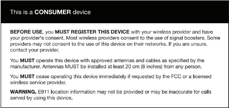
10 Warning
Warning:TheInsideAntennasforvehicleinstallationsmusthave1.5
feetofseparationdistancefromallactiveuser
devices.
Warning:TheInsideAntennasforfixedinstallationsmusthave6feetof
separationdistancefromallactiveusers.
Warning:TheOutdoorAntennasforfixedinstallationsmustbe
installednohigherthan10metersaboveground.

11 Specification
C27G-CPAL-AB-C
Electrical specification Uplink Downlink
Frequency
Range
LTE (A+B) 704~716MHz 734~746MHz
LTE C 776~787MHz 746~757MHz
CDMA 824~849MHz 869~894MHz
PCS 1850~1910MHz 1930~1990MHz
AWS 1710~1755MHz 2110~2155MHz
Band width
LTE (A+B) 12MHz
LTE C 11MHz
CDMA 25MHz
PCS 60MHz
AWS 45MHz
Max .Gain
LTE (A+B) ≤50dB ≤50dB
LTE C ≤50dB ≤50dB
CDMA ≤50dB ≤50dB
PCS ≤50dB ≤50dB
AWS ≤50dB ≤50dB
Max .Output
Power
LTE (A+B) ≤25dBm ≤7dBm
LTE C ≤23dBm ≤3dBm
CDMA ≤23dBm ≤5dBm
PCS ≤23dBm ≤5dBm

AWS ≤23dBm ≤0dBm
Automatic Level Control ≥15dB, auto shut off after 15dB
Inter-modulation 9KHz~12.75GHz ≤-19dBm ≤-19dBm
Spurious
Emission 9KHz~12.75GHz ≤-13dBm ≤-13dBm
LED Alarm Standard
Power LED Power Indicator
ALC LED Orange @ ALC1~5dB, Red @ ALC15dB
LED off after 5 seconds red color.
Mechanical Specifications Standard
I /O Port SMA-Female
Impedance 50 ohm
Operating Temperature 10ºC~+55ºC
Environment Conditions IP40
Dimensions 120*200*30
Weight ≤2.5Kg
Power Supply Input AC90~264V,outputDC12V / 3A