HUAC F10G-CP Dual Band, 60db User Manual F10G CP 1031
SHENZHEN HUAPTEC CO., LTD Dual Band, 60db F10G CP 1031
HUAC >
Users Manual

Consumersignalbooster
usermanual
Content
1HOWITWORKS.....................................................................................4
2TOOLREQUIRED....................................................................................4
3HOWTOINSTALLYOURNEWCELLULARBOOSTER..............................5
3.1Overview......................................................................................5
3.2Planthelayoutofyoursystem....................................................7
3.3CheckforSignalStrength.............................................................7
3.4Runcoaxialcable..........................................................................8
3.5InstalltheDonor(Outdoor)antenna...........................................9
3.6InstalltheServer(Indoor)antenna.............................................9
3.7Installyourcellularbooster......................................................10
3.8Powerupyourcellularbooster................................................10
3.9ChecktheCellularBoosterStatus.............................................11
4UNDERSTANDTHEPORTS,MGCDIPSWITCH,LEDSTATUS...............12
4.1Repeaterports..........................................................................12
4.2LEDstatus..................................................................................12
5UNDERSTANDTHEANTENNA............................................................13
5.1Donor(Outdoor)antenna.........................................................13
5.2Server(Indoor)antenna...........................................................14
5.3Recommending kitingoption................................................14
6TROUBLESHOOTING...........................................................................15
7FREQUENTLYASKEDQUESTIONS.......................................................17
8FCCRFExposureStatement...............................................................19
9Warnning............................................................................................19
10Specification....................................................................................19
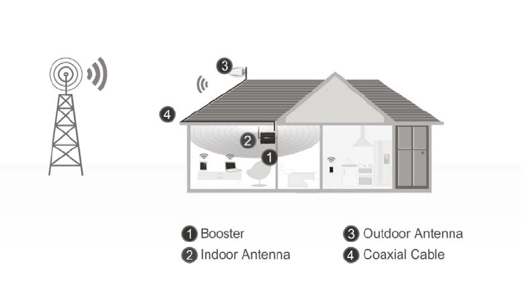
1 HOWITWORKS
Thecellularboosterprovidesreliabletwo‐waycellularcoverageby
improvingsignalstrengthinhomes,buildings,offices,andotherareas
wherecellularreceptionisweakorunreliable.
Thesystemamplifiesthesignalfromthenearestcellulartowerand
retransmitsatahigherpowerlevelwithinalocalarea.
Thismanualprovidessimpleinstallationinstructionsthatwillhaveyour
cellularboosterkitrunninginrecordtime.
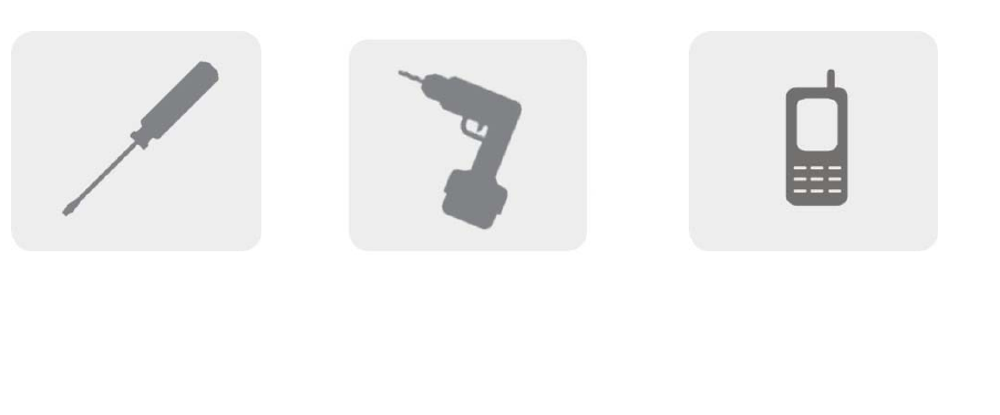
2 TOOLREQUIRED
PhillipsScrewdriver Drill Cellular Phone(tochec
k
signalstrength)
3 HOWTOINSTALLYOURNEWCELLULAR
BOOSTER
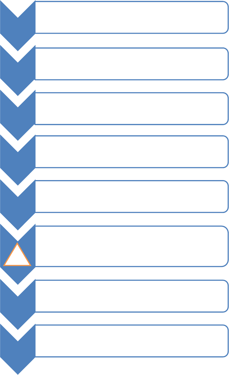
3.1 Overview
Thisguidewillhelpyouproperlyinstallyourcellularboosterkit.Itis
importanttoreadthroughalloftheinstallationstepsbeforeinstalling
yourequipment.Thoroughlyreadthroughtheinstructions,visualize
wherealltheequipmentwillneedtobeinstalledanddoasoft
installationbeforemountinganyequipment.
1
•BOOSTER– selectlocation
•Installtheboosterinanareathatisprotectedfromtheweather,properly
ventilatedandisawayfromexcessiveheatandmoisture.
2
•DONORANTENNA(OUTDOOR)‐selectlocation
•Mountthesignal(outdoor)antennainanelevatedoutdoorlocationso
thatitpointstowardsthecellulartowerandawayfromwheretheinside
antennawillbelocated.
3
•OUTDOORCOAXIALCABLE‐ selectlocation
•Theoutdoorcoaxialcableisusedtoconnectthedonor (outdoor)antenna
tothebooster.
4
•INDOORCOAXIALCABLE‐(ifused)
•Theindoorcoaxialcableisusedtoconnecttheserver(indoor)antennato
thebooster.
5
•SERVERANTENNA(indoor)
•Theideallocationforthedistributionantennawillbetheareaofyour
propertywhereyouneedtoimprovethesignalmost.
•NOTE:Thesignalstrengthwillbestrongestclosesttotheantenna.
•IMPORTANT:Thesignalantenna(outdoor)shouldalwaysbeseparatedfromthe
distributionantenna(indoor)byatleast20verticalfeetincludingtheseparationof
athickbarriersuchasarooforawall.Dependingonthestrengthofyouroutdoor
signal,theweakerthesignalthelessseparationdistanceisrequired.
7
•LIGHTNINGSURGEPROTECTOR‐(SOLDSEPARATELY)
•Thelightningsurgeprotectorconnectsinbetweenthesignalantennaandthe
booster.
•IMPORTANT:Lightningsurgeprotectormustbegrounded.
8• COMMISSIONINGTHESYSTEM
!
3.2 Planthelayoutofyoursystem
Beforeyougetstartedyouwillneedtoplanthelayoutofyoursystem.
Thisinvolvescheckingsignalstrengthforsignalscomingfromthecellular
tower,aswellasantenna,boosterandcableplacement.
3.3 CheckforSignalStrength
Selectalocationontheroofofthebuildingtoinstallthesignalantenna,
bymonitoringyourcellularphone’ssignalstrength(signalbars)tofind
thestrongestsignalfromyourcarrier’scellulartower.
MarkthatareaastheinstallationlocationfortheDonor(outdoor)
IMPORTANT:Confirmthatyouhaveatleast20feetofverticaldistance
betweenthemarkedantennalocationandthelocationwhereyouwill
placetheServer(indoor)antenna.Topreventthesystemfromoscillation
(feedback)youwanttoensurethatthereisenoughseparationbetween
thedistributionandsignalantennaorthattheyareshieldedfromeach
othertoensurethedistributionantennadoesnotsendasignalbackinto
thesignalantenna.Ifyoucannotachievetheseseparations,either
chooseanalternatelocationforthedonor(outdoor)antennaor
determineiftherearenaturalbarriersinthebuildingconstructionitself
thatwillattenuatesignalsbetweenthetwoantennassothatoscillation
canbeprevented.
3.4 Runcoaxialcable
Looselyrunthecoaxialcablefromyouroutdoorantennatoyourbooster.
(Afteryouhavetestedthesystemyoucanpermanentlysecurethe
coaxialcable).
Asyourouteandpullcabling,followthesegeneralguidelines:
Bendcablesandroutethemsmoothly,andprotecttheouterskin
againstanydamage.
Keephorizontalcablesstraightandfastenthemwithatieeverythree
tofivefeet.
Bindandfastenverticalcableseverysixtoeightfeet.
Waterproofalloutdoorconnectionswithsiliconecaulking
Becarefulwhenpluggingtheconnectorinsoasnottodamagethe
centerpinsontheconnectors.
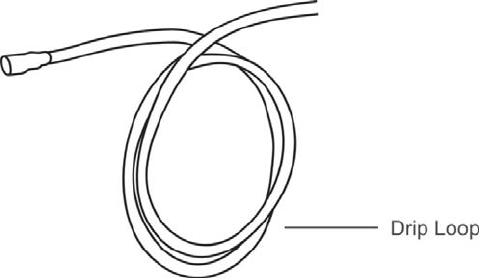
3.5 InstalltheDonor(Outdoor)antenna
Connectthesuppliedcoaxialcabletotheantenna.Werecommend
applyingsiliconecaulkingtofullywaterprooftheconnection.
Attachthecableinsuchawaythatadriploopisformed.
Oncemounted,connectoneendofthecoaxialcabletothedonor
(outdoor)antennaandtheotherendtothecellularboosterwhereitis
marked“outdoor”
3.6 InstalltheServer(Indoor)antenna
Connectoneendofthecoaxialcabletotheantennaandtheotherend
tothecellularboosterwhereitismarked“indoor”.
Selecttheinstallationlocationofyoursuppliedserver(outdoor)antenna
basedonthefollowing:
OmniCeilingdirectionalantenna
Placeinthecenteroftheareawherethesignalneedstobeamplified.
Paneldirectionalantenna
Placeintheouterperimeteroftheareathesignalneedstobeamplified.
WhipOmnidirectionalantenna
Mountdirectlytotheconnectormarked“indoor”onthecellularbooster.
3.7 Installyourcellularbooster
Installthecellularboosterinalocationthatisproperlyventilatedand
notexposedtoexcessiveheat,moistureand/ordirectsunlight.The
optimalareawouldbeonawalllocatednearapoweroutlet.
Itshouldbemountedinaneasilyaccessibleareasoit’seasytoperform
generalmaintenancewiththecoaxialcableconnections,dipswitch
settingsandpoweradaptor.
Makesureallcablesandantennasaresecurelyconnectedbefore
commissioningthesystem.
3.8 Powerupyourcellularbooster
OncealltheFollowingprecautionshavebeentaken,poweronthe
cellularbooster.
1. Verifythatyouhaveleftatleast20feetofverticalseparationspacebetweenthe
indoorandoutdoorantennas.
2. Neverpointthefrontoftheyagidonor(outdoor)antennatowardstheinsideof
theserver(outdoor)antenna.
3. Verifythatthesuppliedcoaxialcablesfromboththedonor(outdoor)antenna
andtheserver(outdoor)antennaareproperlyconnectedtothecellularbooster
beforepoweringitup.
4. Carefullypluginthesuppliedpoweradaptorintothebackofthecellularbooster
whereitismarked‘power’andconnecttheotherendtoapoweroutlet.
TheLEDindicatormarkedpowershouldlightupgreen.
3.9 ChecktheCellularBoosterStatus
Yourcellularboostercomesequippedwithelectronicsensorsdesigned
toidentifycellularsignaloverloadoroscillationwhichcanhindersignal
boostingperformance.Yourcellularboosterisspeciallydesignedto
automaticallydecreasegaintocompensateforthesecircumstances.The
devicealsohasafeaturetoautomaticallyshutdownincaseofexcessive
oscillation.Improperequipmentinstallationandunusablesignalquality
cancauseoscillation,thisiswhyitisimportanttofullyunderstandthe
LEDalarmlightsonyourbooster,astheywillhelpyouidentifyandsolve
anypotentialissues.
ThecoloroftheLEDindicatesthestatusoftheboostersystem.
4 UNDERSTANDTHEPORTS,MGCDIP
SWITCH,LEDSTATUS
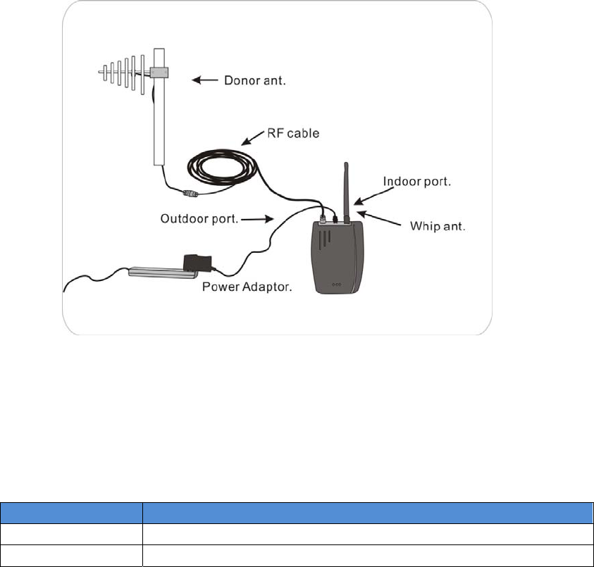
4.1 Repeaterports
1) Outdoor port: connected with the donor antenna by cable.
2) Indoor port: connected with server antenna directly or by cable.
3) DC IN: connected with power supply.
4.2 LEDstatus
1. StatusanddefinitionofPOWERindicators:
Status Definition
Green Normal
Off DC power problem
2. StatusandDefinitionofALARMindicators;AlarmLEDonlyworksfor
downlinksignals
Status ALARM
Green It is working in linearity
attention: Input signals may be not enough
Red There are overloading or self-oscillation, strong input signals,
measures shall be taken
Orange
It is working in linearity
Attention: Please adjust MGC to increase the attenuation value, till you
find the “edge point” ( I.E. the Alarm LED shall stay at green color, with
intention of turning Orange), and let the repeater work at this point.
Off Repeater break down
5 UNDERSTANDTHEANTENNA
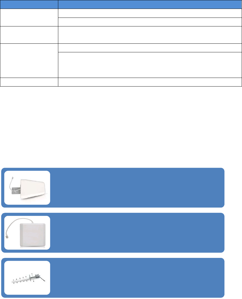
5.1 Donor(Outdoor)antenna
TheYagiLpdaAntenna
Theyagiisaveryprecisedirectionalantennawithapowerfulreach.This
antennashouldbeinstalledinanelevatedpositionandmustbepointed
towardsyourcarrier’scellulartower.
NOTE:Thisantennaisnotmeanttocapturesignalfrommultiplecarriers.
ThePanelAntenna
Thepanelisadirectionalantennawitha120degreereachandisdesignedto
capturethesignalfrommultiplecarriertowers.Thisantennashouldbe
installedinanelevatedpositionandmustbepointedtowardsyourcarrier’s
cellulartowers.
YagiAntenna
Theyagiisaveryprecisedirectionalantennawithapowerfulreach.This
antennashouldbeinstalledinanelevatedpositionandmustbepointed
towardsyourcarrier’scellulartower.
NOTE:Thisantennacanonlysupportsinglebandsignalbooster.
5.2 Server(Indoor)antenna
5.3 Recommending kitingoption
OutsideAntennakitOptionsInsideAntennakitOptions
1Kit11‐30501Kit5‐0
2Kit11‐504002Kit100‐1550
3Kit11‐50503Kit100‐30400
4Kit11‐754004Kit100‐5050
5Kit11‐1004005Kit100‐7550
6Kit11‐75506Kit102‐7550‐50
7Kit11‐100507Kit103‐7550‐75
8Kit10‐304008Kit114‐7550‐50
9Kit10‐30509Kit100‐10050
10Kit10‐5040010Kit100‐30400
11Kit10‐505011Kit100‐50400
12Kit10‐7540012Kit100‐75400
13Kit10‐10040013Kit3‐0350
14Kit10‐755014Kit3‐1550
15Kit10‐1005015Kit3‐30400
16Kit9‐3040016Kit3‐5050
17Kit9‐305017Kit3‐7550
18Kit9‐5040018Kit3‐10050
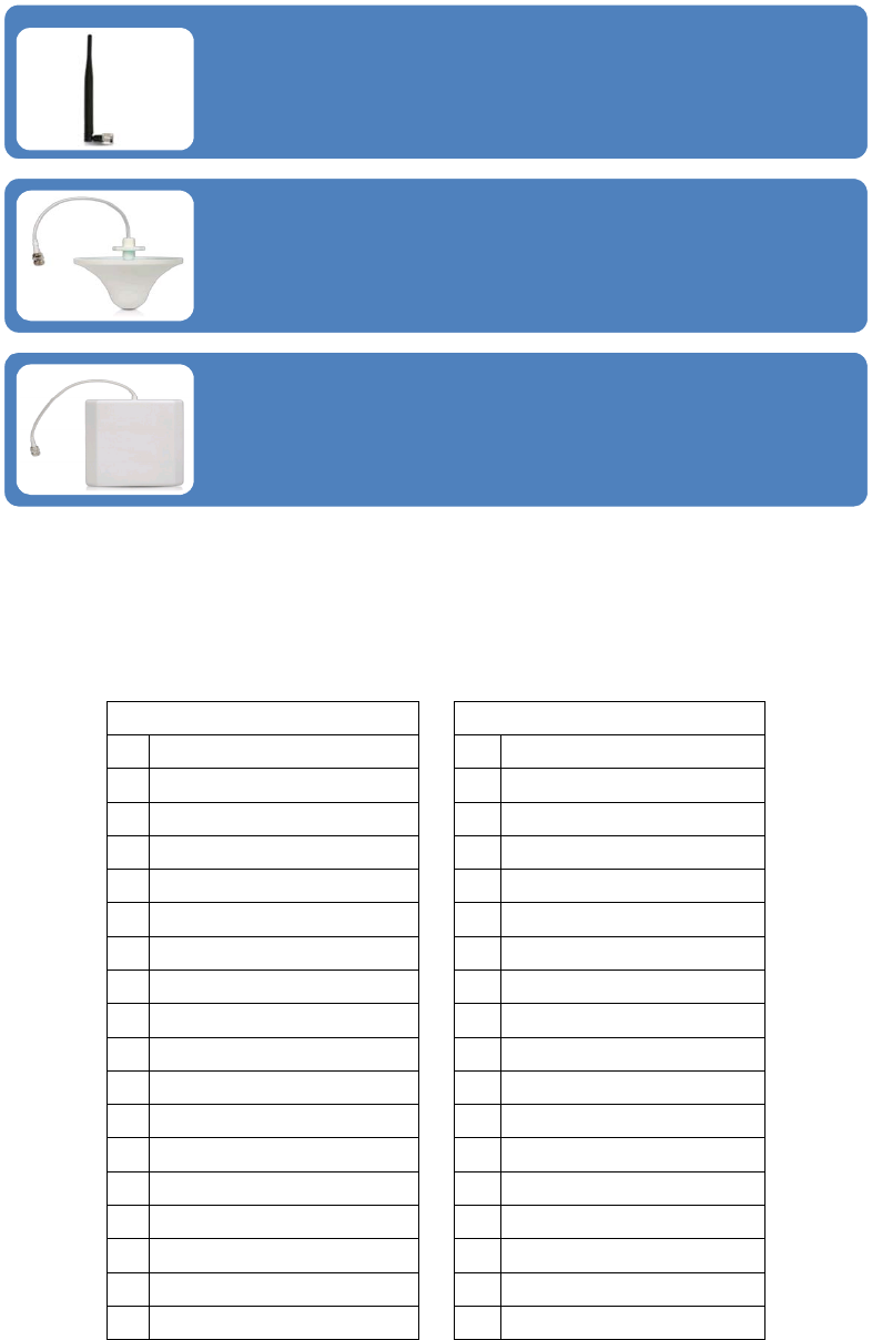
TheWhipAntenna
Thewhipantennaisanomni‐directionalantennawitha360degreereach.It
isdesignedtodistributethesignalfromthecenteroftheaffectedarea.
Typicallyitisconnecteddirectlytothebooster.
TheOmniAntenna
Theomniantennaisanomni‐directionalantennawitha360degreereach.It
isdesignedtodistributethesignalfromthecenteroftheaffectedarea.
Typicallyitisinstalledinafalseordroppedceiling.
ThePanelAntenna
Thepanelisadirectionalantennawitha120degreereachandisdesignedto
distributethesignalfromaperimeterwallorceiling.
19Kit9‐505019Kit3‐30400
20Kit9‐7540020Kit3‐50400
21Kit9‐10040021Kit3‐75400
22Kit9‐755022Kit3‐100400
23Kit9‐1005023Kit32‐50400‐50
24Kit5‐3040024Kit33‐50400‐75
25Kit5‐305025Kit34‐50400‐50
26Kit5‐50400
27Kit5‐5050
28Kit5‐75400
29Kit5‐100400
30Kit5‐7550
31Kit5‐10050
6 TROUBLESHOOTING
TheLEDalarmlightsrepresentthestatusoftheboosteroneach
frequency.Whenthelightsaregreenthedeviceisoperatingnormally
meaningthatitisnotexperiencinganyoscillation(feedback)anditis
boostingthesignalatmaximumpower.WhentheLEDlightsbeginto
changecolorfromgreentoorangetored,itmeansthatparticular
frequencyisexperiencingsomeoscillation(feedback).
Iftheoscillationisexcessivetheboosterwillshutdownforthatparticular
frequency.Theboosterwillstillworkfortheotherfrequencyona
multi‐bandbooster.

Oscillationiscausedwhentheindoor(distribution)antennasendsa
signalbackintotheoutdoor(signal)antenna.SimilartoaPAsystem,
whenthemicrophonegetstooclosetothespeakeritcausesfeedback.
Thiswilloccurifyourantennasaretooclosetogether,ortheindoor
antennaispointedattheoutdoorantenna.Makesureyouhave
adequateseparationandsometypeofshieldingbetweentheantennas
(Usuallyyourrooforacementwallisgoodenough).
IMPORTANTNOTES
The2mostimportantthingstolookforwhensettingupyoursystemis:
Bycapturingthebestinputsignalyouwillbeabletoenjoythemaximum
coverageandbestqualitysignalinsidewhereyourIndoorantennasare
located.Thebettertheinputsignal,thebettertheoutputsignal.Inorder
tofindthebestinputsignal,youwanttoplaceyouroutdoorantennaas
highaspossiblewiththeleastamountofobstructionbetweenthe
antennaandthecellularbasetower.Aclearlineofsiteisideal.
Agoodinputsignal(thebestyoucanfind)
Isolatingtheoutdoor(donor)antennafromtheindoor
(server)antennassotheydonotfeedbackintoeach
other.

Isolatingthesignalfromtheantennasisdonebyensuringthatthe
antennasarenotpointingtoeachotherandbyhavingenoughdistance
orbarriershieldinginbetweenthem.Thesignalstravellikeraysof
sunlight,adirectionalantennawillsendthesignalinthedirectionthatit
ispointing.Anomnidirectionalantennawillsendthesignalinevery
directionaroundit.Sodependingonyourequipmentit’simportanttobe
surethatyourIndoorantennaisnotsendingthesignalbackintothe
outdoorantenna.
THINGSTOCHECKWHENEXPERIENCINGWEAKCELLULARSIGNAL
1. Ensuretheoutdoorantennaispointinginthecorrectdirectionandis
capturingadequatesignalforthebooster.
2. Checkallconnectionsonthecable,antennas,andbooster.
3. Checkcableforbendsandorcuts.
4. AllLEDlightsontheboostershouldbegreen.
5. Outdoorantennaandtheindoorantennashaveadequateseparation
andarenotcausingfeedback.
7 FREQUENTLYASKEDQUESTIONS
WHYARETHELEDLIGHTSTURNINGORANGE,REDOR
SHUTTINGOFF?
Therearecertaincaseswhereyoursystemcouldbeexperiencing
oscillation.Thiscanbeattributedtoeitherthequalityofyourinput
signalorhavingyouroutdoorantennaandindoorantennatooclose
together.Pleasereviewthefollowingguidelinestohelpresolvethis
issue:
1. Adjustthedirectionoftheoutdoorantenna.Ifthesystemis
receivingaveryhighinputsignal,youcanpointyouroutdoor
antennaawayfromthecellulartowertoreducethestrengthofthe
inputsignalandtherefore,reducetheoscillation.Alternativelyif
yoursystemisreceivingaverypoorqualitysignal(weakand
unusablesignal),youcanpointyouroutdoorantennamoredirectly
towardsthecellulartowertoincreasethestrengthoftheinputsignal.
Sometimesthismayrequirecompletelyrepositioningtheantennato
alocationwhereyoucanachievealineofsitetothetower.
2. Increasetheseparationbetweentheoutdoorantennaandthe
indoorantenna.Thiscanbeachievedbyincreasingthedistance
betweenthetwoantennasorbyplacingbarriersbetweenthem,
suchasmovingtheindoorantennatoanadjacentroomwherethere
wouldbeanadditionalwallseparatingthemfromtheoutdoor
antenna.
3. ManualGainControl.Adjustthegainwiththemanualgaincontrol
functionusingthedipswitchesonthesideofthebooster.
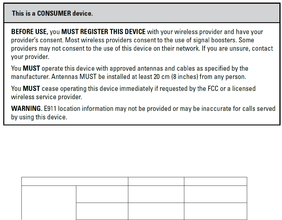
8 FCCRFExposureStatement
ThisequipmentcomplieswithFCCradiationexposurelimitssetforthfor
anuncontrolledenvironment.Endusersmustfollowthespecific
operatinginstructionforsatisfyingRFexposurecompliance.This
transmittermustnotbeco‐locatedoroperatinginconjunctionwithany
otherantennaortransmitter.
9 Warning
10 Specification
F10G-CP
Electrical specification Uplink Downlink
Frequency Range Cell 824~849MHz 869~894MHz
PCS 1850~1910MHz 1930~1990MHz

Band width Cell 25 MHz
PCS 60 MHz
Max .Gain Cell ≤58dB ≤58dB
PCS ≤63dB ≤63dB
Max .Output Power Cell 20dBm 0dBm
PCS 23dBm 0dBm
MGC ( Step Attenuation ) 31dB/1dBstep
Automatic Level Control ≥15dB, auto shut off after 15dB
Inter-modulation 9KHz~12.75GHz ≤-19dBm ≤-19dBm
Spurious Emission 9KHz~12.75GHz ≤-13dBm ≤-13dBm
LED Alarm Standard
Power LED Power Indicator
ALC LED Orange @ ALC1~5dB, Red @ ALC15dB
LED off after 5 seconds red color.
Mechanical Specifications Standard
I /O Port N-Female
Impedance 50 ohm
Operating Temperature 10ºC~+55ºC
Environment Conditions IP40
Dimensions 120*135*30
Weight ≤3Kg
Power Supply Input AC90~264V,outputDC12V / 3A