HUAC F20G-CPAL-AB-C Consumer Booster User Manual Manual Rev1
SHENZHEN HUAPTEC CO., LTD Consumer Booster Manual Rev1
HUAC >
Manual Rev1

Customer signal booster
user manual
Content
WHAT IS INCLUDED .................................................................................. 3
1 HOW IT WORKS .................................................................................. 3
2 TOOL REQUIRED ................................................................................. 3
3 HOW TO INSTALL YOUR NEW CELLULAR BOOSTER ............................. 4
3.1 Overview ................................................................................... 4
3.2 Plan the layout of your system .................................................. 6
3.3 Check for Signal Strength .......................................................... 6
3.4 Run coaxial cable ....................................................................... 7
3.5 Install the Donor (Outdoor) antenna ......................................... 7
3.6 Install the Server (Indoor) antenna ............................................ 8
3.7 Install your cellular booster ....................................................... 9
3.8 Power up your cellular booster ................................................. 9
3.9 Check the Cellular Booster Status ............................................ 10
4 UNDERSTAND THE PORTS, MGC DIP SWITCH, LED STATUS ............... 11
4.1 Repeater ports ........................................................................ 11
4.2 LED status ................................................................................ 11
5 UNDERSTAND THE ANTENNA ........................................................... 12
5.1 Donor (Outdoor) antenna ....................................................... 12
5.2 Server (Indoor) antenna .......................................................... 12
5.3 Authorized Kitting Options ...................................................... 13
6 TROUBLESHOOTING ......................................................................... 15
7 FREQUENTLY ASKED QUESTIONS ...................................................... 17
8 FCC RF Exposure Statement ............................................................. 18
9 Warning ........................................................................................... 18
10 Specification .................................................................................. 19
WHAT IS INCLUDED
1. Booster F20G-CPAL-AB-C
2. Outdoor Yagi 9dbi Antenna & 50’5D Coaxial Cable
3. Indoor Panel 10dbi Antenna& 50’5D Coaxial Cable
4. AC/DC Power Adapter
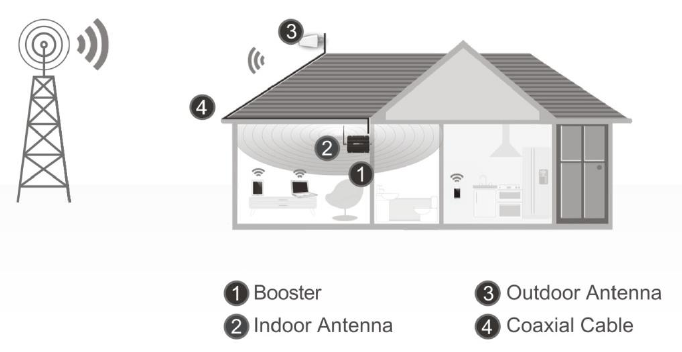
1 HOW IT WORKS
The cellular booster provides reliable two-way cellular coverage by improving
signal strength in homes, buildings, offices, and other areas where cellular
reception is weak or unreliable.
The system amplifies the signal from the nearest cellular tower and
retransmits at a higher power level within a local area.
This manual provides simple installation instructions that will have your
cellular booster kit running in record time.
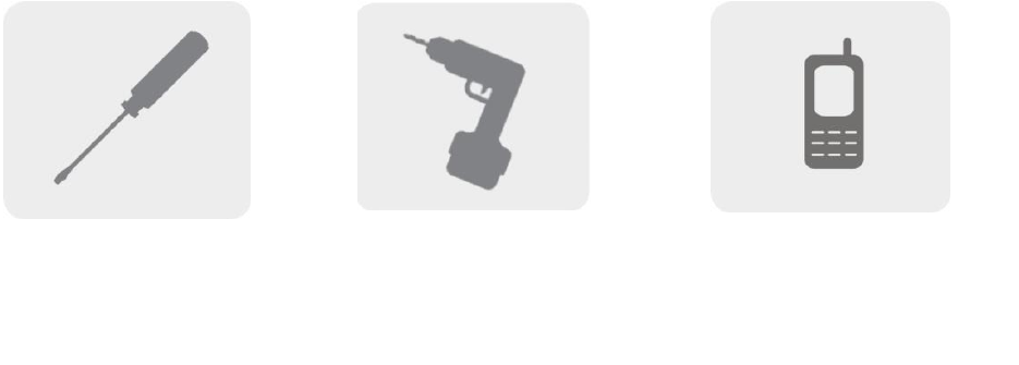
2 TOOL REQUIRED
Phillips Screwdriver
Drill
Cellular Phone (to check signal
strength)
3 HOW TO INSTALL YOUR NEW CELLULAR BOOSTER
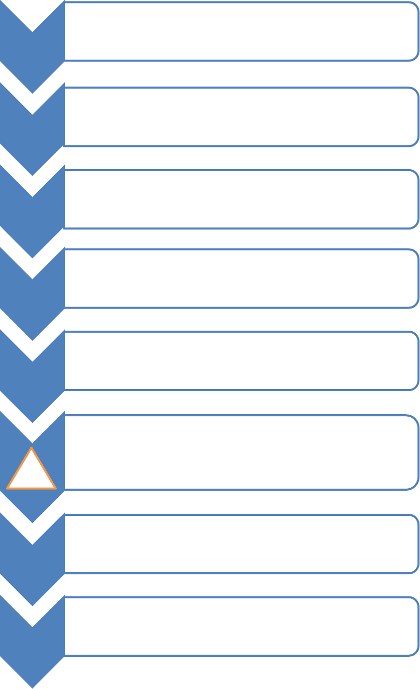
3.1 Overview
This guide will help you properly install your cellular booster kit. It is important
to read through all of the installation steps before installing your equipment.
Thoroughly read through the instructions, visualize where all the equipment
will need to be installed and do a soft installation before mounting any
equipment.
1
•BOOSTER – select location
•Install the booster in an area that is protected from the weather, properly
ventilated and is away from excessive heat and moisture.
2
•DONOR ANTENNA (OUTDOOR)- select location
•Mount the signal (outdoor) antenna in an elevated outdoor location so
that it points towards the cellular tower and away from where the inside
antenna will be located.
3
•OUTDOOR COAXIAL CABLE - select location
•The outdoor coaxial cable is used to connect the donor (outdoor) antenna
to the booster.
4
•INDOOR COAXIAL CABLE- (if used)
•The indoor coaxial cable is used to connect the server (indoor) antenna to
the booster.
5
•SERVER ANTENNA (indoor)
•The ideal location for the distribution antenna will be the area of your
property where you need to improve the signal most.
•NOTE:The signal strength will be strongest closest to the antenna.
•IMPORTANT: The signal antenna (outdoor)should always be separated from the
distribution antenna (indoor)by at least 20 vertical feet including the separation of
a thick barrier such as a roof or a wall. Depending on the strength of your outdoor
signal, the weaker the signal the less separation distance is required.
7
•LIGHTNING SURGE PROTECTOR- (SOLD SEPARATELY)
•The lightning surge protector connects in between the signal antenna and the
booster.
•IMPORTANT: Lightning surge protector must be grounded.
8 •COMMISSIONING THE SYSTEM
• !
!
3.2 Plan the layout of your system
Before you get started you will need to plan the layout of your system. This
involves checking signal strength for signals coming from the cellular tower, as
well as antenna, booster and cable placement.
3.3 Check for Signal Strength
Select a location on the roof of the building to install the signal antenna, by
monitoring your cellular phone’s signal strength (signal bars) to find the
strongest signal from your carrier’s cellular tower.
Mark that area as the installation location for the Donor (outdoor)
IMPORTANT: Confirm that you have at least 20 feet of vertical distance
between the marked antenna location and the location where you will place
the Server (indoor) antenna. To prevent the system from oscillation (feedback)
you want to ensure that there is enough separation between the distribution
and signal antenna or that they are shielded from each other to ensure the
distribution antenna does not send a signal back into the signal antenna. If you
cannot achieve these separations, either choose an alternate location for the
donor (outdoor) antenna or determine if there are natural barriers in the
building construction itself that will attenuate signals between the two
antennas so that oscillation can be prevented.
3.4 Run coaxial cable
Loosely run the coaxial cable from your outdoor antenna to your booster.
(After you have tested the system you can permanently secure the coaxial
cable).
As you route and pull cabling, follow these general guidelines:
Bend cables and route them smoothly, and protect the outer skin against
any damage.
Keep horizontal cables straight and fasten them with a tie every three to
five feet.
Bind and fasten vertical cables every six to eight feet.
Waterproof all outdoor connections with silicone caulking
Be careful when plugging the connector in so as not to damage the center
pins on the connectors.
3.5 Install the Donor (Outdoor) antenna
Connect the supplied coaxial cable to the antenna. We recommend applying
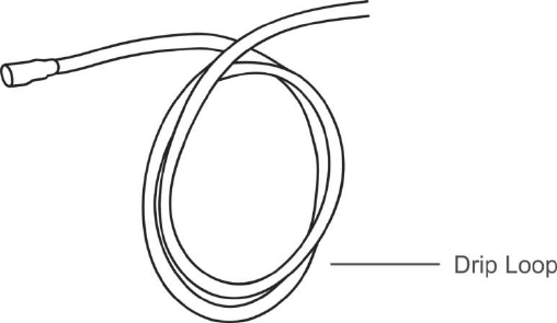
silicone caulking to fully waterproof the connection.
Attach the cable in such a way that a drip loop is formed.
Once mounted, connect one end of the coaxial cable to the donor (outdoor)
antenna and the other end to the cellular booster where it is marked
“outdoor”
3.6 Install the Server (Indoor) antenna
Connect one end of the coaxial cable to the antenna and the other end to the
cellular booster where it is marked “indoor”.
Select the installation location of your supplied server (outdoor) antenna
based on the following:
Omni Ceiling directional antenna
Place in the center of the area where the signal needs to be amplified.
Panel directional antenna
Place in the outer perimeter of the area the signal needs to be amplified.
Whip Omni directional antenna
Mount directly to the connector marked “indoor” on the cellular booster.
3.7 Install your cellular booster
Install the cellular booster in a location that is properly ventilated and not
exposed to excessive heat, moisture and/or direct sunlight. The optimal area
would be on a wall located near a power outlet.
It should be mounted in an easily accessible area so it’s easy to perform
general maintenance with the coaxial cable connections, dip switch settings
and power adaptor.
Make sure all cables and antennas are securely connected before
commissioning the system.
3.8 Power up your cellular booster
Once all the Following precautions have been taken, power on the cellular
booster.
1. Verify that you have left at least 20 feet of vertical separation space between the
indoor and outdoor antennas.
2. Never point the front of the yagi donor (outdoor) antenna towards the inside of
the server (outdoor)antenna.
3. Verify that the supplied coaxial cables from both the donor (outdoor) antenna
and the server (outdoor)antenna are properly connected to the cellular booster
before powering it up.
4. Carefully plug in the supplied power adaptor into the back of the cellular booster
where it is marked ‘power’ and connect the other end to a power outlet.
The LED indicator marked power should light up green.
3.9 Check the Cellular Booster Status
Your cellular booster comes equipped with electronic sensors designed to
identify cellular signal overload or oscillation which can hinder signal boosting
performance. Your cellular booster is specially designed to automatically
decrease gain to compensate for these circumstances. The device also has a
feature to automatically shut down in case of excessive oscillation. Improper
equipment installation and unusable signal quality can cause oscillation, this is
why it is important to fully understand the LED alarm lights on your booster, as
they will help you identify and solve any potential issues.
The color of the LED indicates the status of the booster system.
4 UNDERSTAND THE PORTS, MGC DIP SWITCH, LED STATUS
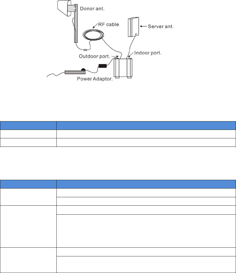
4.1 Repeater ports
1) Outdoor port: connected with the donor antenna by cable.
2) Indoor port: connected with server antenna directly or by cable.
3) DC IN: connected with power supply.
4.2 LED status
1. Status and definition of POWER indicators:
Status
Definition
Green
Normal
Off
DC power problem
2. Status and Definition of ALARM indicators; Alarm LED only works for
downlink signals
Status
ALARM
Green
It is working in linearity
Attention: Input signals may be not enough
Flashing Green
It is working in linearity.
Attention: Please adjust MGC to increase the attenuation value, till
you find the “edge point” ( I.E. the Alarm LED shall stay at green
color, with intention of turning flashing green), and let the repeater
work at this point.
Flashing Red
Repeater shut off
There are overloading or self-oscillation, strong input signals,
measures shall be taken
5 UNDERSTAND THE ANTENNA
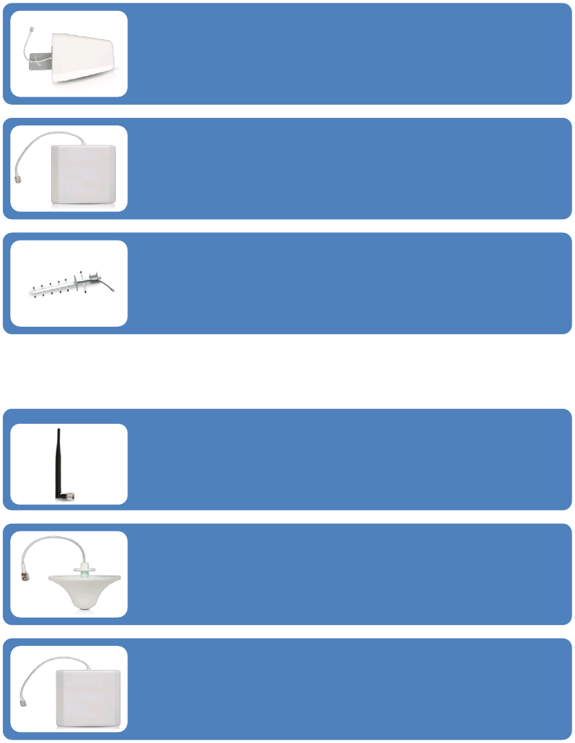
5.1 Donor (Outdoor) antenna
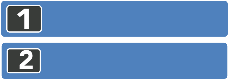
5.2 Server (Indoor) antenna
The Yagi Lpda Antenna
The yagi is a very precise directional antenna with a powerful reach. This
antenna should be installed in an elevated position and must be pointed
towards your carrier’s cellular tower.
NOTE:This antenna is not meant to capture signal from multiple carriers.
The Panel Antenna
The panel is a directional antenna with a 120 degree reach and is designed to
capture the signal from multiple carrier towers. This antenna should be
installed in an elevated position and must be pointed towards your carrier’s
cellular towers.
Yagi Antenna
The yagi is a very precise directional antenna with a powerful reach. This
antenna should be installed in an elevated position and must be pointed
towards your carrier’s cellular tower.
NOTE: This antenna can only support single band signal booster.
The Whip Antenna
The whip antenna is an omni-directional antenna with a 360 degree reach. It
is designed to distribute the signal from the center of the affected area.
Typically it is connected directly to the booster.
The Omni Antenna
The omni antenna is an omni-directional antenna with a 360 degree reach. It
is designed to distribute the signal from the center of the affected area.
Typically it is installed in a false or dropped ceiling.
The Panel Antenna
The panel is a directional antenna with a 120 degree reach and is designed to
distribute the signal from a perimeter wall or ceiling.
5.3 Authorized Kitting Options
Outdoor Default Antenna & Cable Kit Options
1. Kit 9-5050
Outdoor Yagi 9dbi Antenna & 50’ 5D Coaxial Cable
Indoor Default Antenna & Cable Kit Options
1. Kit 102-5050-50
2 Panel 10dbi Antenna &50' 5D N male & a 50 Ohm 2-Way Splitter
Outdoor Antenna & Cable Kit Options
2.Kit 11-100400
Yagi 11dbi Antennac& 100' 400 Coaxial Cable
3. Kit 11-7550
Yagi 11dbi Antenna & 75' 5D Coaxial Cable
4. Kit 11-100500
Yagi 11dbi Antenna & 100' 5D Coaxial Cable
5. Kit 10-3050
Panel 10dbi Antenna & 30' 5D Coaxial Cable
6. Kit 10-50400
Panel 10dbi Antenna & 50' 400 Coaxial Cable
7. Kit 10-5050
Panel 10dbi Antenna & 50' 5D Coaxial Cable
8. Kit 10-75400
Panel 10dbi Antenna & 75' 400 Coaxial Cable
9. Kit 10-100400
Panel 10dbi Antenna & 100' 400 Coaxial Cable
10. Kit 10-7550
Panel 10dbi Antenna & 75' 5D Coaxial Cable
11. Kit 10-10050
Panel 10dbi Antenna & 100' 5D Coaxial Cable
12. Kit 9-50400
Yagi 9dbi Antenna & 50' 400 Coaxial Cable
13. Kit 9-75400
Yagi 9dbi Antenna & 75' 400 Coaxial Cable
14. Kit 9-100400
Yagi 9dbi Antenna & 100' 400 Coaxial Cable
15. Kit 9-7550
Yagi 9dbi Antenna & 75' 5D Coaxial Cable
16. Kit 9-10050
Yagi 9dbi Antenna & 100' 5D Coaxial Cable
17. Kit 5-30400
Omni 5dbi Antenna & 30' 400 Coaxial Cable
18. Kit 5-3050
Omni 5dbi Antenna & 30' 5D Coaxial Cable
19. Kit 5-50400
Omni 5dbi Antenna & 50' 400 Coaxial Cable
20. Kit 5-5050
Omni 5dbi Antenna & 50' 5D Coaxial Cable
21. Kit 5-75400
Omni 5dbi Antenna & 75' 400 Coaxial Cable
22. Kit 5-10400
Omni 5dbi Antenna & 100' 400 Coaxial Cable
23. Kit 5-7550
Omni 5dbi Antenna & 75' 5D Coaxial Cable
24. Kit 5-10050
Omni 5dbi Antenna & 100' 5D Coaxial Cable
Indoor Antenna & Cable Kit Options
2. Kit 52-5050-50
2 Whip 5dbi Antenna &50' 5D Coaxial Cable & a 50 Ohm 2-Way Splitter
3. Kit 103-7550-50
3 Panel 10dbi Antenna & 75' 5D Coaxial Cable & a 50Ohm 3-Way Splitter
4. kit 104-7550-50
4 Panel 10dbi Antenna & 75' 5D Coaxial Cable & three 50 Ohm 2-Way Splitter
5. Kit 3-1550
Omni 3dBi Antenna with 15' 5D Coaxial Cable
6. Kit 3-30400
Omni 3dBi Antenna with 30' 400 Coaxial Cable
7. Kit 3-5050
Omni 3dBi Antenna & 50' 5D Coaxial Cable
8. Kit 3-7550
Omni 3dBi Antenna & 75' 5D Coaxial Cable
9. Kit 3-10050
Omni 3dBi Antenna & 100' 5D Coaxial Cable
10. Kit 3-30400
Omni 3dBi Antenna with 30' 400 Coaxial Cable
11. Kit 3-50400
Omni 3dBi Antenna & 50' 400 Coaxial Cable
12. Kit 3-75400
Omni 3dBi Antenna & 75' 400 Coaxial Cable
13. Kit 3-100400
Omni 3dBi Antenna & 100' 400 Coaxial Cable
14. Kit 32-50400-50
2 Omni 3dBi Antenna & 50' 400 Coaxial Cable & a 50 Ohm 2-Way Splitter
15. Kit 33-50400-50
3 Omni 3dBi Antenna & 50' 400 Coaxial Cable & a 50 Ohm 3-Way Splitter
16. Kit 34-50400-50
4 Omni 3dBi Antenna &50' 400 Coaxial Cable & three 50 Ohm 2-Way Splitter
6 TROUBLESHOOTING
The LED alarm lights represent the status of the booster on each frequency.
When the lights are green the device is operating normally meaning that it is
not experiencing any oscillation (feedback) and it is boosting the signal at
maximum power. When the LED lights begin to change status from green to
flashing green to flashing red, it means that particular frequency is
experiencing some oscillation (feedback).
If the oscillation is excessive the booster will shut down for that particular
frequency. The booster will still work for the other frequency on a multi-band
booster.
Oscillation is caused when the indoor (distribution) antenna sends a signal
back into the outdoor (signal) antenna. Similar to a PA system, when the
microphone gets too close to the speaker it causes feedback. This will occur if
your antennas are too close together, or the indoor antenna is pointed at the
outdoor antenna. Make sure you have adequate separation and some type of
shielding between the antennas
(Usually your roof or a cement wall is good enough).
IMPORTANT NOTES
The 2 most important things to look for when setting up your system is:
By capturing the best input signal you will be able to enjoy the maximum
coverage and best quality signal inside where your Indoor antennas are
located. The better the input signal, the better the output signal. In order to
find the best input signal, you want to place your outdoor antenna as high as
possible with the least amount of obstruction between the antenna and the
cellular base tower. A clear line of site is ideal.
Isolating the signal from the antennas is done by ensuring that the antennas
are not pointing to each other and by having enough distance or barrier
shielding in between them. The signals travel like rays of sunlight, a directional
antenna will send the signal in the direction that it is pointing. An omni
directional antenna will send the signal in every direction around it. So
depending on your equipment it’s important to be sure that your Indoor
antenna is not sending the signal back into the outdoor antenna.
THINGS TO CHECK WHEN EXPERIENCING WEAK CELLULAR SIGNAL
1. Ensure the outdoor antenna is pointing in the correct direction and is
capturing adequate signal for the booster.
A good input signal (the best you can find)
Isolating the outdoor (donor) antenna from the indoor
(server) antennas so they do not feedback into each
other.

2. Check all connections on the cable, antennas, and booster.
3. Check cable for bends and or cuts.
4. All LED lights on the booster should be green.
5. Outdoor antenna and the indoor antennas have adequate separation and
are not causing feedback.
7 FREQUENTLY ASKED QUESTIONS
WHY ARE THE LED LIGHTS TURNING FLASHING GREEN, FLASHING
RED OR SHUTTING OFF?
There are certain cases where your system could be experiencing oscillation.
This can be attributed to either the quality of your input signal or having your
outdoor antenna and indoor antenna too close together. Please review the
following guidelines to help resolve this issue:
1. Adjust the direction of the outdoor antenna. If the system is receiving a
very high input signal, you can point your outdoor antenna away from the
cellular tower to reduce the strength of the input signal and therefore,
reduce the oscillation. Alternatively if your system is receiving a very poor
quality signal (weak and unusable signal), you can point your outdoor
antenna more directly towards the cellular tower to increase the strength
of the input signal. Sometimes this may require completely repositioning
the antenna to a location where you can achieve a line of site to the tower.
2. Increase the separation between the outdoor antenna and the indoor
antenna. This can be achieved by increasing the distance between the two
antennas or by placing barriers between them, such as moving the indoor
antenna to an adjacent room where there would be an additional wall
separating them from the outdoor antenna.
3. Manual Gain Control. Adjust the gain with the manual gain control
function using the dip switches on the side of the booster.
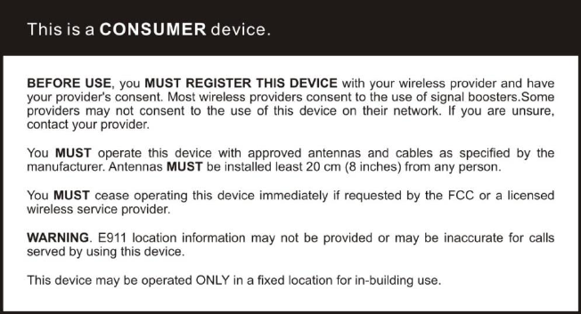
8 FCC RF Exposure Statement
This equipment complies with FCC radiation exposure limits set forth for an
uncontrolled environment. End users must follow the specific operating
instruction for satisfying RF exposure compliance. This transmitter must not be
co-located or operating in conjunction with any other antenna or transmitter.
9 Warning
Warning: The Outdoor Antennas must be installed no higher than 10
meters above ground.
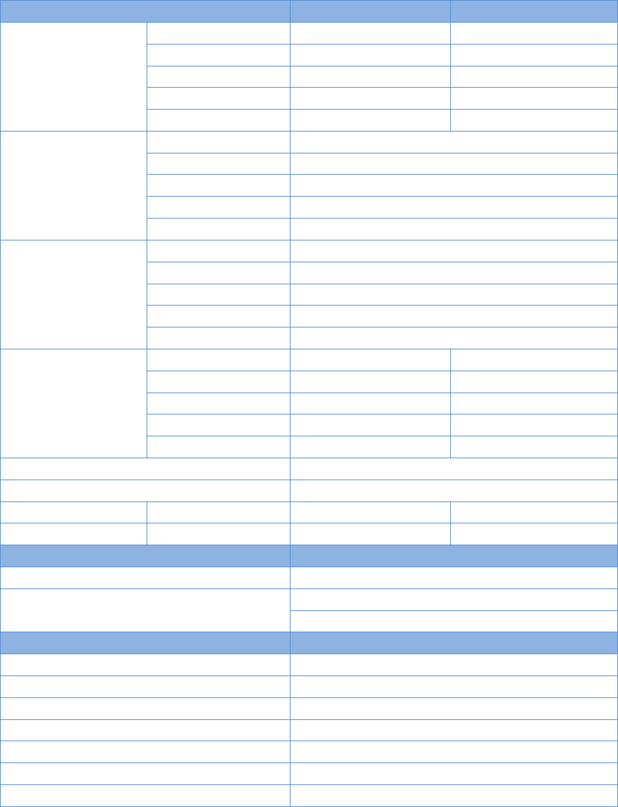
10 Specification
F20G-CPAL-AB-C
Electrical specification
Uplink
Downlink
Frequency Range
LTE (A+B)
704~716MHz
734~746MHz
LTE C
776~787MHz
746~757MHz
CDMA
824~849MHz
869~894MHz
PCS
1850~1910MHz
1930~1990MHz
AWS
1710~1755MHz
2110~2155MHz
Band width
LTE (A+B)
12MHz
LTE C
11MHz
CDMA
25MHz
PCS
60MHz
AWS
45MHz
Max .Gain
LTE (A+B)
≤63dB
LTE C
≤64dB
CDMA
≤64dB
PCS
≤70dB
AWS
≤70dB
Max .Output Power
LTE (A+B)
≤25dBm
≤10dBm
LTE C
≤25dBm
≤10dBm
CDMA
≤25dBm
≤10dBm
PCS
≤25dBm
≤10dBm
AWS
≤25dBm
≤10dBm
MGC ( Step Attenuation )
31dB/1dBstep
Automatic Level Control
≥ 15dB, auto shut off after 15dB
Inter-modulation
9KHz~12.75GHz
≤-19dBm
≤-19dBm
Spurious Emission
9KHz~12.75GHz
≤-13dBm
≤-13dBm
LED Alarm
Standard
Power LED
Power Indicator
ALC LED
Flashing green @ ALC 1~15dB
Flashing red @ auto shut off after ALC 15dB
Mechanical Specifications
Standard
I /O Port
N-Female
Impedance
50 ohm
Operating Temperature
10ºC~+55ºC
Environment Conditions
IP40
Dimensions
218*165*50
Weight
≤ 2.5Kg
Power Supply
Input AC90~264V,output DC12V / 3A