HUIZHOU GAOSHENGDA TECHNOLOGY W7LM1110 WIFI module User Manual
Hui Zhou Gaoshengda Technology Co.,LTD WIFI module Users Manual
User Manual
PRODUCT SPECIFICATION Version 2.0
IEEE 802.11 b/g/n
1T/1R
USB Module
Model Number: W7LM1110 / W7LM1110A
客户认可
Custom Approval Section
Custom Name
Department
Approval
Date:
拟制
DESIGN
审核
CHECK
批准
APPROVAL
朱晓辉
陈宇科
熊运自
2016-11-24
2016-11-24
2016-11- 24
制造商:惠州高盛达科技有限公司
Manufacturer: HUIZHOU GAOSHENGDA TECHNOLOGY CO.,LTD
中国惠州仲恺高新技术开发区华宇路 75 号
HUA YU RD., NO.75, ZHONGKAI HIGH-TECH DEVELOPMENT AREA, HUIZHOU, CHINA
TEL:(0752)2096698 FAX:(0752)2096628 E-mail:zhuxh@gaosd.cn
PRODUCTS SPECIFICATION
PAGE 2 OF 19
W7LM1110
Version2.0
Document revision history
Revision
Date
Approved by
Remarks
Version 1.0
2016-09-23
Draft
Version 1.1
2016-09-29
Update:add Schematic diagram
add label list &Package
add Appendix 4
Version 1.2
2016-09-30
Update:add FCC ID/IC ID
Version 1.3
2016-09-30
Update:Operating Voltage
Module label/picture
Version 1.4
2016-10-03
Update:Module picture
Version 1.5
2016-10-11
Update:
Appendix 5:
Reliability test report
Appendix6:Salt spray test report
Model test report
Version 1.6
2016-10-14
Update:add Appendix 7: PCB Information
Version 1.7
2016-10-20
Update:Mechanical Dimensions
Version 1.8
2016-10-27
Update:1.25mm*8PIN SMT connector
Part List
Add IPEX Connector
Module picture
Version 1.9
2016-11-01
Update:Mechanical Dimensions
Version 2.0
2016-11-24
Update:Package

PRODUCTS SPECIFICATION
PAGE 3 OF 19
W7LM1110
Version2.0
1. General Description
This document is to specify the product requirements for 802.11 b/g/n USB Module.This Module is
based on Media Tek MT7601U chipset that complied with IEEE 802.11g, IEEE 802.11b, IEEE
802.11n standard from 2.4G-2.5GHz,and it can be used to provide up to 54Mbps for 802.11g,11Mbps
for 802.11b and 150Mbps for 802.11n to connect your wireless LAN.
With seamless roaming, fully interoperability and advanced security with WEP standard,
802.11b/g/n USB Module offers absolute interoperability with different vendors 802.11 b, 802.11 g,
802.11n Access Points through the wireless LAN.
2. Features
● Compatible with IEEE 802.11b standard to provide wireless 11Mbps data rate.
● Compatible with IEEE 802.11g standard to provide wireless 54Mbps data rate.
● Compatible with IEEE 802.11n standard to provide wireless 150Mbps data rate.
● Operation at 2.4G-2.5GHz frequency band to meet worldwide regulations
● Supports WEP ,WPA ,WPA2,TKIP,AES enhanced security
● Drivers support Windows XP 32/64, 2000, 7,Vista 32/64, Linux OS
● High speed USB 2.0 interface
● RoHS compliant

PRODUCTS SPECIFICATION
PAGE 4 OF 19
W7LM1110
Version2.0
3. Application Diagrams
3.1 Functional Block Diagram
DC/DC
3.3V
5V
WL/2.4G/ Tx/Rx
Interface Signals
3.2 Schematic diagram
USB Interface
MT7601U
40MHz
XTAL
Antenna
PRODUCTS SPECIFICATION
PAGE 5 OF 19
W7LM1110
Version2.0
4. General Requirements
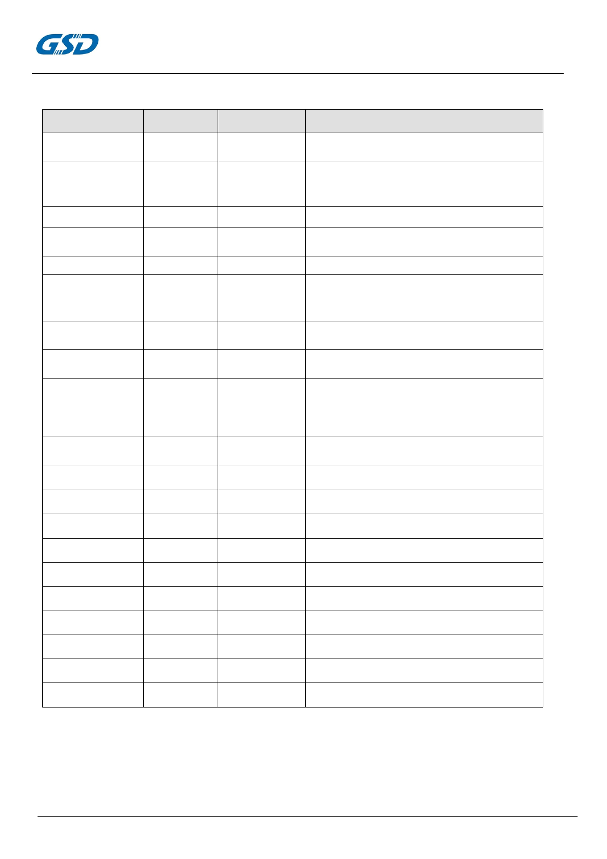
4.1 IEEE 802.11b Section
#
Feature
Detailed Description
4.1.1
Standard
●IEEE 802.11b
4.1.2
Radio and
Modulation
Schemes
●DQPSK , DBPSK , DSSS , and CCK
4.1.3
Operating
Frequency
●2400 ~2497MHz ISM band
4.1.4
Channel Numbers
●11 channels for United States
●13 channels for Europe Countries(Default)
●14 channels for Japan
4.1.5
Data Rate
●11,5.5,2,and 1Mbps
4.1.6
Media Access
Protocol
●CSMA/CA with ACK
4.1.7
Transmitter
Output
Power at Antenna
Connector
●Typical RF Output Power at each RF chain,Data Rate and at
room Temp. 25degree C
●17±1.5dBm at 11Mbps
4.1.8
Receiver
Sensitivity
at Antenna
Connector
●Typical Sensitivity at Which Frame(1000-byte PDUs)Error
Rate=8% at room Temp 25 degree C
●-90 dBm at 2Mbps
●-81 dBm for 11Mbps
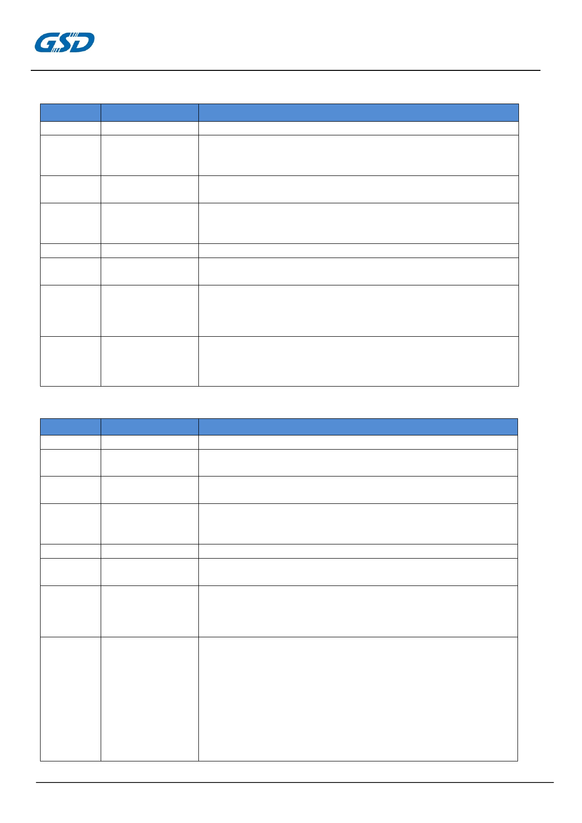
4.2 IEEE 802.11g Section
#
Feature
Detailed Description
4.2.1
Standard
●IEEE 802.11g
4.2.2
Radio and
Modulation Type
●QPSK , BPSK , 16QAM ,64QAM with OFDM
4.2.3
Operating
Frequency
●2400 ~2483.5MHz ISM band
4.2.4
Channel Numbers
●11 channels for United States
●13 channels for Europe Countries(Default)
●13 channels for Japan
4.2.5
Data Rate
●6,9,12,18,24,36,48,54Mbps
4.2.6
Media Access
Protocol
●CSMA/CA with ACK
4.2.7
Transmitter
Output
Power at Antenna
Connector
●Typical RF Output Power(tolerance±1.5dBm) at each RF chain,
Data Rate and at roomTemp. 25 degree C
●14±1.5 dBm at 54Mbps
4.2.8
Receiver
Sensitivity
at Antenna
Connector
●Typical Sensitivity at each RF chain. Frame(1000-byte
PDUs)Error Rate=10% at room Temp 25 degree C
●-87 dBm at 6Mbps
●-86 dBm at 9Mbps
●-84 dBm at 12Mbps
●-82 dBm at 18Mbps
●-80 dBm at 24Mbps
●-76 dBm at 36Mbps
●-72 dBm at 48Mbps
●-71 dBm at 54Mbps
PRODUCTS SPECIFICATION
PAGE 6 OF 19
W7LM1110
Version2.0
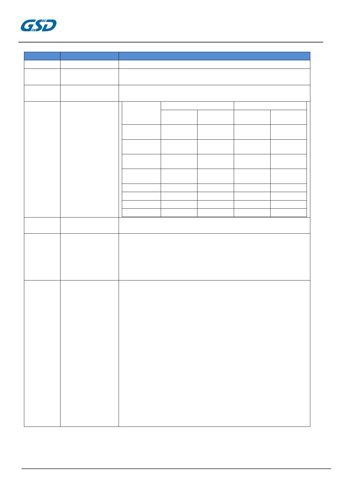
4.3 IEEE 802.11n Section
#
Feature
Detailed Description
4.3.1
Standard
●IEEE 802.11n
4.3.2
Radio and
Modulation Type
●BPSK , QPSK , 16QAM ,64QAM with OFDM
4.3.3
Operating
Frequency
●2400 ~2483.5MHz
4.3.4
Data Rate(Mbps)
MCS
GI=800ns
GI=400ns
20MHz
40MH
20M
z
40MHz
0
6.5
1
.5
7.
15
1
13
27
14.4
3
2
19.5
40.5
21.7
4
26
54
28.
60
4
39
81
43.3
90
5
52
108
57.8
120
6
58.5
121.5
65.0
135
7
65
135
72.2
150
4.3.5
Media Access
Protocol
● CSMA/CA with ACK
4.3.6
Transmitter
Output
Power at Antenna
Connector
●Typical RF Output Power(tolerance±1.5dBm) at each RF
chain,Data Rate and at roomTemp. 25degree C
HT-20
●14±1.5dBm at MCS7
HT-40
●14±1.5dBm at MCS7
4.3.7
Receiver
Sensitivity
at Antenna
Connector
●Typical Sensitivity at Which Frame(1000-byte PDUs)Error
Rate=10% at roomTemp. 25degree C
HT-20
●-87dBm at MCS0/8
●-84dBm at MCS1/9
●-82dBm at MCS2/10
●-79dBm at MCS3/11
●-76dBm at MCS4/12
●-72dBm at MCS5/13
●-70dBm at MCS6/14
●-69dBm at MCS7/15
HT-40
●-84dBm at MCS0/8
●-81dBm at MCS1/9
●-80dBm at MCS2/10
●-76dBm at MCS3/11
●-73dBm at MCS4/12
●-69dBm at MCS5/13
●-68dBm at MCS6/14
●-66dBm at MCS7/15
PRODUCTS SPECIFICATION
PAGE 7 OF 19
W7LM1110
Version2.0
5.Electrical and Thermal Characteristics
5.1 EEPROM Information
Reg Domain
Worldwide
Configured by driver
Offset 0x38 for 5G:0xFF
Offset 0x39 for 2.4G:0xFF
Vendor ID
0x148F
Product ID
0x7601
5.2 Temperature Limit Ratings
Parameter
Minimum
Maximum
Storage Temperature
-40
℃
+80
℃
Storage Relative Humidity
5-90%(non-condensing)
Operating ambient Temperature
0
℃
+80
℃
Operating Relative Humidity
5-95%(non-condensing)
Note: The above temperature is the ambient temperature recommended
modules run
5.3 General Section
#
Feature
Detailed Description
5.3.1
Antenna Type
● PIFA antenna
5.3.2
Operating Voltage
● 5.0V±5%
5.3.3
Form Factor and Interface
● High Speed USB2.0 Interface
5.3.4
Connector
● 1.25-8 pin connector (see appendix)
5.4 Software
Driver
Windows XP 32/64, 2000, 7,Vista 32/64, Linux OS
Security
WEP ,WPA ,WPA2,TKIP,AES
5.5 Power consumption
Power
consumption
mode
Average
Max:1A
TX
240mA
RX
200mA
Associated Idle mode
160mA
unassociated Idle mode
70mA
PRODUCTS SPECIFICATION
PAGE 8 OF 19
W7LM1110
Version2.0
Remarks: Strongly recommend TV platform has to fulfill output current at
least 1A
5.6 Recommended operation conditions for module
Symbol
Rating
Min
Typ
Max
units
VCC
5V supply
4.75
5
5.25
V
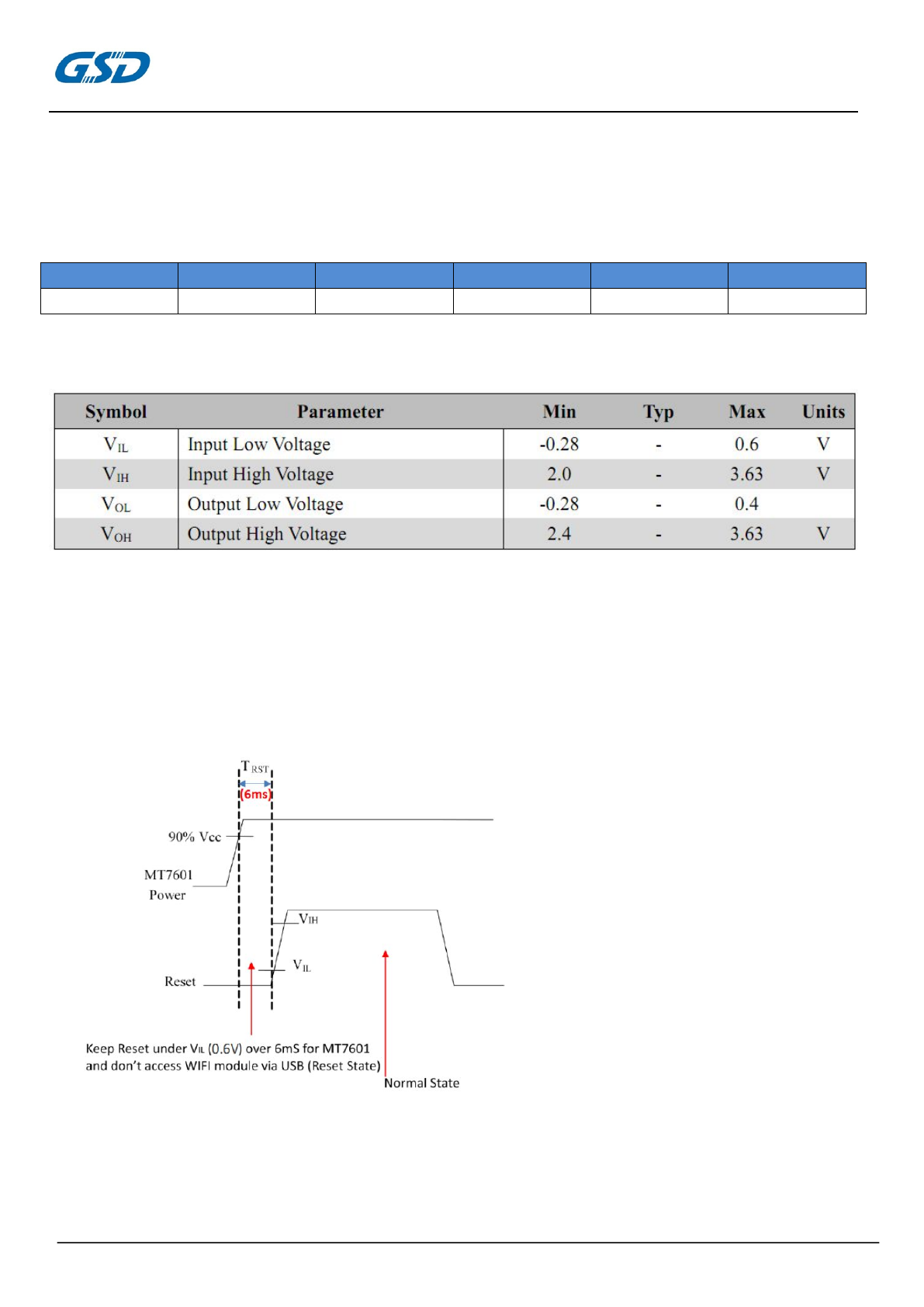
5.7 DC characteristics
5.8 WoWLAN
Wake Up System Via WiFi,High Active
5.9 Reset Timing SPEC
System Reset MT7601u ,Low Active
PRODUCTS SPECIFICATION
PAGE 9 OF 19
W7LM1110
Version2.0
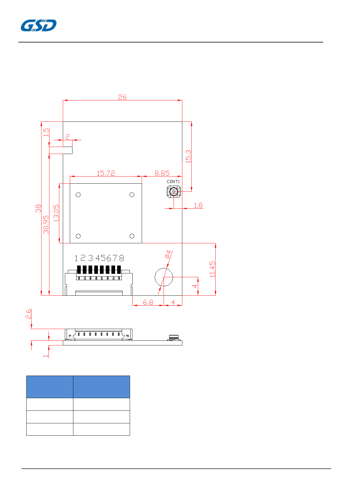
5.10 Mechanical Dimensions(unit:mm)
5.11 Pin Description
1.25-8 Pin connector
DIM
(MM)
Tolerance
(MM)
0-5
±0.15
5-10
±0.20
10-50
±0.30
PRODUCTS SPECIFICATION
PAGE 10 OF 19
W7LM1110
Version2.0
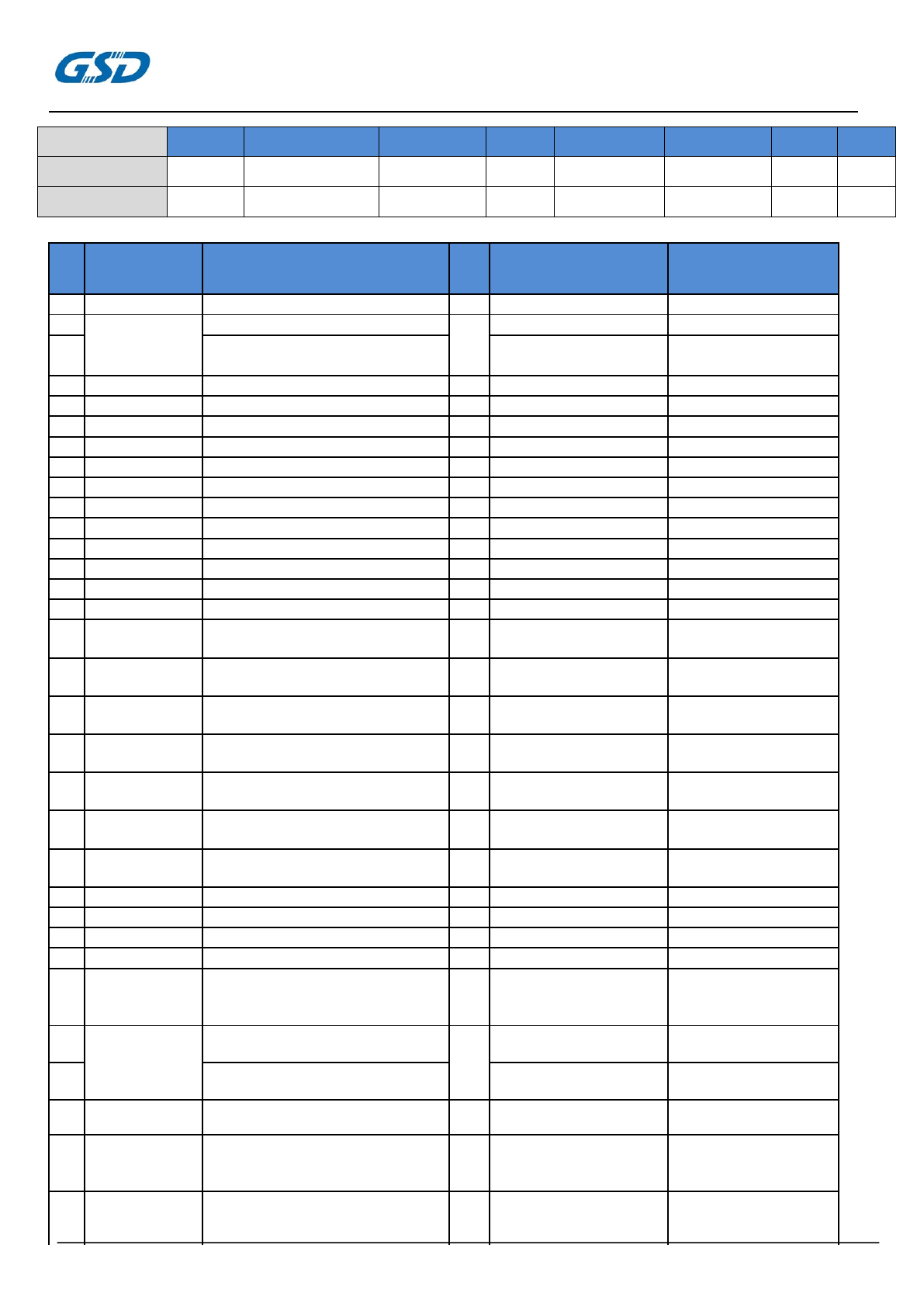
Part List
序
Type
Specification model
Numb
Manufacturer P/N
Manufacturer
号
er
1
IC
MT7601U
1
MT7601U
MTK
2
FP6381A
1
FP6381A
FITI
3
DC-DC
RT8059GJ5/DC/DC
RT8059
RICHTEK
converter,1.5MHz,1A,TSOT-23-5
4
Capacitance
0201/50V/1pF/±0.1pF/COG
1
GRM0335C1H1R0BA01D
MURATA
5
Capacitance
0201/50V/1.2pF/±0.1pF/COG
2
GRM0335C1H1R2BA01D
MURATA
6
Capacitance
0201/50V/4.7pF/±0.1pF/COG
2
GRM0335C1H4R7BA01D
MURATA
7
Capacitance
0201/50V/5.6pF/±0.25pF/COG
2
GRM0335C1H5R6CA01D
MURATA
8
Capacitance
0201/50V/22pF/±5%/C0G
1
GRM0335C1H220JA01D
MURATA
9
Capacitance
0201/50V/47pF/±5%/COG
1
GRM0335C1H470JA01D
MURATA
10
Capacitance
0201/10V/0.1uF/±10%/X5R
13
GRM033R61A104KE15D
MURATA
11
Capacitance
0402/50V/0.5pF/±0.1pF/C0G
1
GRM1555C1HR50BA01D
MURATA
12
Capacitance
0402/50V/10pF/±0.5pF/C0G
1
GRM1555C1H100JA01D
MURATA
13
Capacitance
0402/10V/1uF/±10%/X5R
5
GRM155R61A105KE15D
MURATA
14
Capacitance
0402/6.3V/2.2uF/±20%/X5R
1
GRM155R60J225ME95D
MURATA
15
Capacitance
0603/6.3V/10uF/±20%/X5R
2
GRM188R60J106ME47D
MURATA
16
Resistance
0201 1/20W 0Ω ±5%
1
WR02X000 PAL
/
WALSIN/YAGEO
RC0201JR-070R
17
Resistance
0201 1/20W 8.2KΩ ±5%
1
WR02X103 JAL
/
WALSIN/YAGEO
RC0201JR-078K2
18
Resistance
0201 1/20W 10KΩ ±5%
1
WR02X103 JAL
/
WALSIN/YAGEO
RC0201JR-0710K
19
Resistance
0201 1/20W 100KΩ ±5%
1
WR02X104 JAL
/
WALSIN/YAGEO
RC0201JR-07100K
20
Resistance
0402 1/16W 22KΩ ±5%
1
WR04X223 JTL /
WALSIN/YAGEO
RC0402JR-0722K
21
Resistance
0402 1/16W 24KΩ ±5%
1
WR04X243 JTL /
WALSIN/YAGEO
RC0402JR-0724K
22
Resistance
0402 1/16W 100KΩ ±5%
1
WR04X104 JTL /
WALSIN/YAGEO
RC0402JR-07100K
23
Inductance
0201/2.7nH/±0.1nH
2
LQP03TN2N7B02D
MURATA
24
Inductance
0201/18nH/±5%
2
LQP03TN18NJ02D
MURATA
25
Inductance
0402/1.0nH/±0.3nH
1
LQG15HN1N0S02D
MURATA
26
Inductance
0805/4.7uH/±20%/700mA
1
MPB201210T-4R7M-NA2
MURATA
Crystal
(H.ELE)
27
40MHz,CL=15pF,10ppm,LF
1
3225/40M
(CREC)
oscillator
SMD/3.2X2.5
28
IPEX
W08-5801-002-00-810
1
W08-5801-002-00-
810
(zhongjun)
29
RMVRN-33300-TP00
RMVRN-33300
-TP00
(youqun)
30
Shield
WF7E
1
WF7E
(RunDa)
31
Connector
1
A1253WRA-S-08PNLBT1
T00R
(canda)
1.25/WS/8/A1253WRA-S-08PNL
BT1T00R
32
PCB
W7L-2/155*137.6*1.0/20
1
W7L
(FuZhiXiang),
(KeXiang)
Pin
1
2
3
4
5
6
7
8
Pin Define
GND
WoW
RESET
GND
USB_D+
USB_D-
VCC
VCC
Description
GND
Wake WLAN
RESET
GND
USB Data+
USB Data-
5V
5V
PRODUCTS SPECIFICATION
PAGE 11 OF 19
W7LM1110
Version2.0
(ZHONGSHAN
33
label
1
15*12.5mm/
FUZHOU ADHESIVE-
W7LM1110
pet
PRODUCT CO.,LTD)
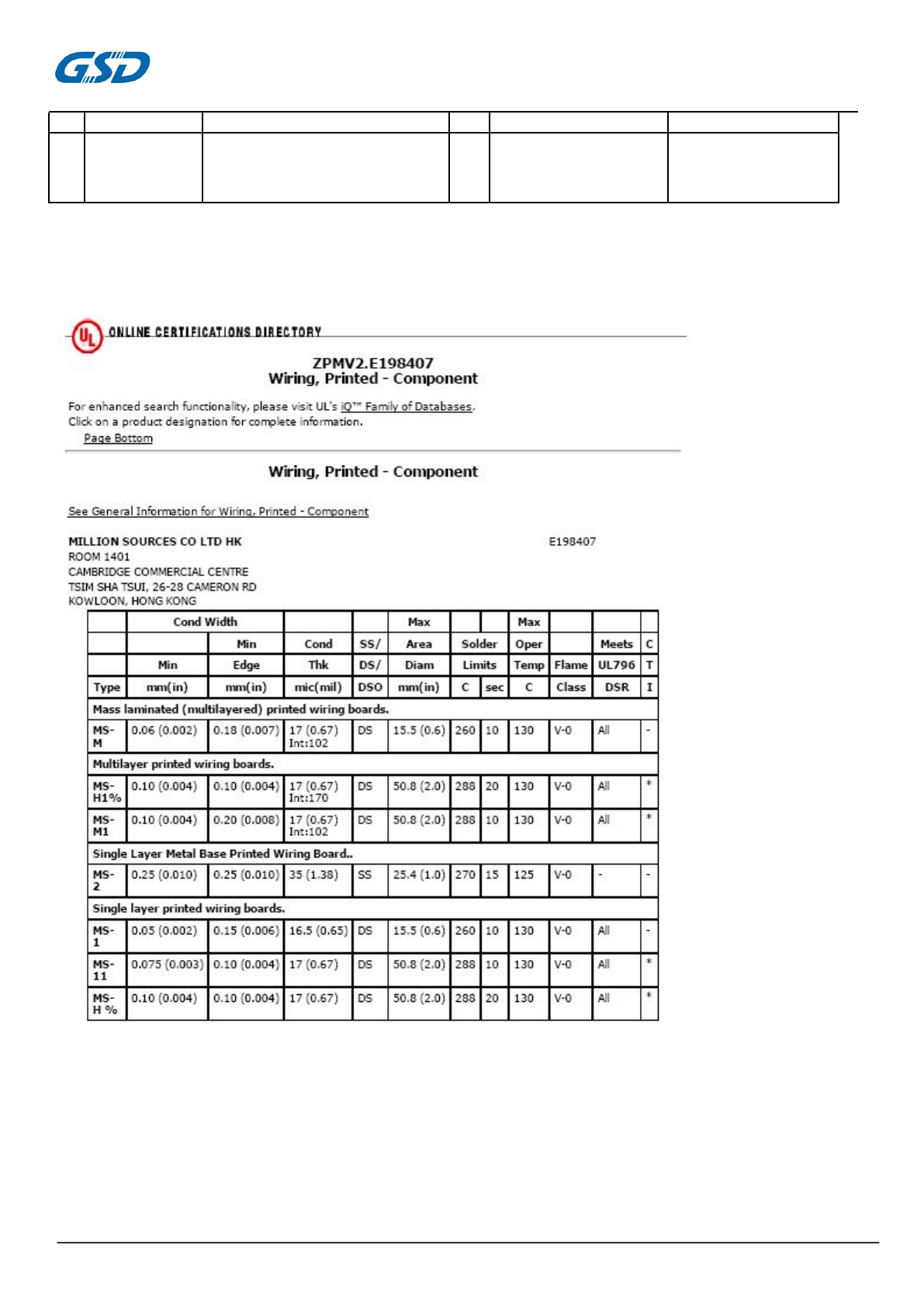
PCB Information
PCB UL Certification
PRODUCTS SPECIFICATION
PAGE 12 OF 19
W7LM1110
Version2.0
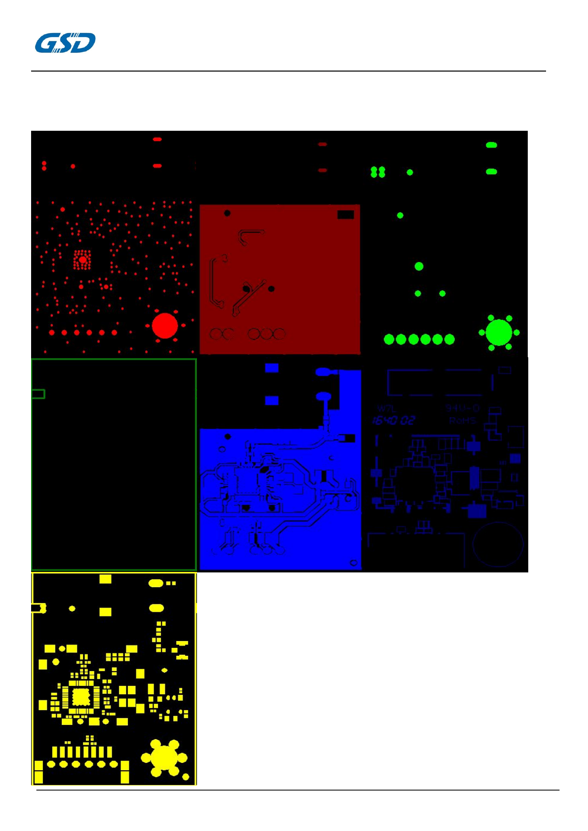
PCB gerber

PRODUCTS SPECIFICATION
PAGE 13 OF 19
W7LM1110
Version2.0
FCC Requirement
changes or modifications not expressly approved by the party responsible for compliance could void the
user’s authority to operate the equipment.
This device complies with Part 15 of the FCC Rules. Operation is subject to the following two conditions:
(1) this device may not cause harmful interference, and
(2) this device must accept any interference received, including interference that may cause undesired
operation.
Note: This equipment has been tested and found to comply with the limits for a Class B digital device,
pursuant to Part 15 of the FCC Rules. These limits are designed to provide reasonable protection against
harmful interference in a residential installation. This equipment generates, uses, and can radiate radio
frequency energy, and if not installed and used in accordance with the instructions, may cause harmful
interference to radio communications. However, there is no guarantee that interference will not occur in
a particular installation. If this equipment does cause harmful interference to radio or television
reception, which can be determined by turning the equipment off and on, the user is encouraged to try
to correct the interference by one or more of the following measures:
– Reorient or relocate the receiving antenna.
– Increase the separation between the equipment and receiver.
– Connect the equipment into an outlet on a circuit different from that to which the receiver is
connected.
– Consult the dealer or an experienced radio/TV technician for help.
Please notice that if the FCC identification number is not visible when the module is installed inside
another device, then the outside of the device into which the module is installed must also display a label
referring to the enclosed module. This exterior label can use wording such as the following: “Contains
FCC ID: 2AC23-W7LM1110” any similar wording that expresses the same meaning may be used.

PRODUCTS SPECIFICATION
PAGE 14 OF 19
W7LM1110
Version2.0
IC Requirement
This device complies with Industry Canada license-exempt RSS standard(s). Operation is subject to the
following two conditions: (1) this device may not cause interference, and (2) this device must accept any
interference, including interference that may cause undesired operation of the device.
Cet appareil est conforme aux CNR exempts de licence d'Industrie Canada. Le fonctionnement est
soumis aux deux conditions suivantes:
(1) Cet dispositif ne peut causer des interférences; et
(2) Cet appareil doit accepter toute interférence, y compris les interférences qui peuvent causer un
mauvais fonctionnement de l'appareil.
Please notice that if the IC identification number is not visible when the module is installed inside
another device, then the outside of the device into which the module is installed must also display a label
referring to the enclosed module. This exterior label can use wording such as the following: “Contains IC:
12290A-W7LM1110” any similar wording that expresses the same meaning may be used.
l'appareil hôte doit porter une étiquette donnant le numéro de certification du module d'Industrie
Canada, précédé des mots « Contient un module d'émission », du mot « Contient » ou d'une formulation
similaire exprimant le même sens, comme suit

This equipment should be installed and operated with a minimum distance of 20cm
between the radiator and any part of your body.
(1) user manual Information:
The module is limited to OEM installation ONLY
The module is limited to installation in mobile or fixed applications.
The OEM integrator has to be aware not to provide information to the end user
regarding how to install or remove this RF module in the user's manual of the end
product which integrates this module. The end user manual shallinclude all required
regulatory information/warning as show in this manual.
(2) Co-location Warning:
This device and its antenna(s) must not be co-located or operating in conjunction with
any other antenna or transmitter.
(3) OEM integration instructions:
This device is intended only for OEM integrators under the following conditions:
The transmitter module may not be co-located with any other transmitter or antenna.
The module shall be only used with the integral antenna(s) that has been originally
tested and certified with this module.
As long as 2 conditions above are met, further transmitter test will not be required.
However, the OEM integrator is still responsible for testing their end-product for any
additional compliance requirements required with this module installed (for example,
digital device emissions, PC peripheral requirements, etc.).
In the event that these conditions cannot be met (for example certain laptop
configuration or co-location with another transmitter), then the FCC authorization for
this module in combination with the host equipment is no longer considered valid and
the FCC ID of the module cannot be used on the final product. In these and
circumstance, the OEM integrator will be responsible for re-evaluating. The end
product (including the transmitter) and obtaining a separate FCC authorization.
PRODUCTS SPECIFICATION
W7LM1110
PAGE 15OF 19
Version2.0