HUIZHOU GAOSHENGDA TECHNOLOGY WC0DR2611 WIFI Module User Manual
Hui Zhou Gaoshengda Technology Co.,LTD WIFI Module Users Manual
User Manual

PRODUCT SPECIFICATION Version 1.3
IEEE
802.11 a/b/g/n/ac
2T/2R Dual Band
Module
Model Number:
WC0DR2611
HUIZHOU GAOSHENGDA TECHNOLOGY CO.,LTD
HUA YU RD., NO.75, ZHONGKAI HIGH-TECH DEVELOPMENT AREA, HUIZHOU, CHINA
TEL:( 0752)2096698
PRODUCTS SPECIFICATION
PAGE 2 OF 12
WC0DR2611
Version 1.3
Document revision history
Revision
Date
Approved by
Remarks
Version 1.0
2016-05-25
Draft
Version 1.1
2016-05-26
1、 Connector :change 6PIN to
5PIN
2、 ADD Mechanical Dimensions:
Module A ,Module B
Version 1.2
2016-05-31
1、 Modify Mechanical
Dimensions
2、 Modify ANT2 SPEC
Version 1.3
2016-06-07
3、 Modify Connector SPEC
4、 Modify ANT2 SPEC
PRODUCTS SPECIFICATION
PAGE 3 OF 12
WC0DR2611
Version 1.3
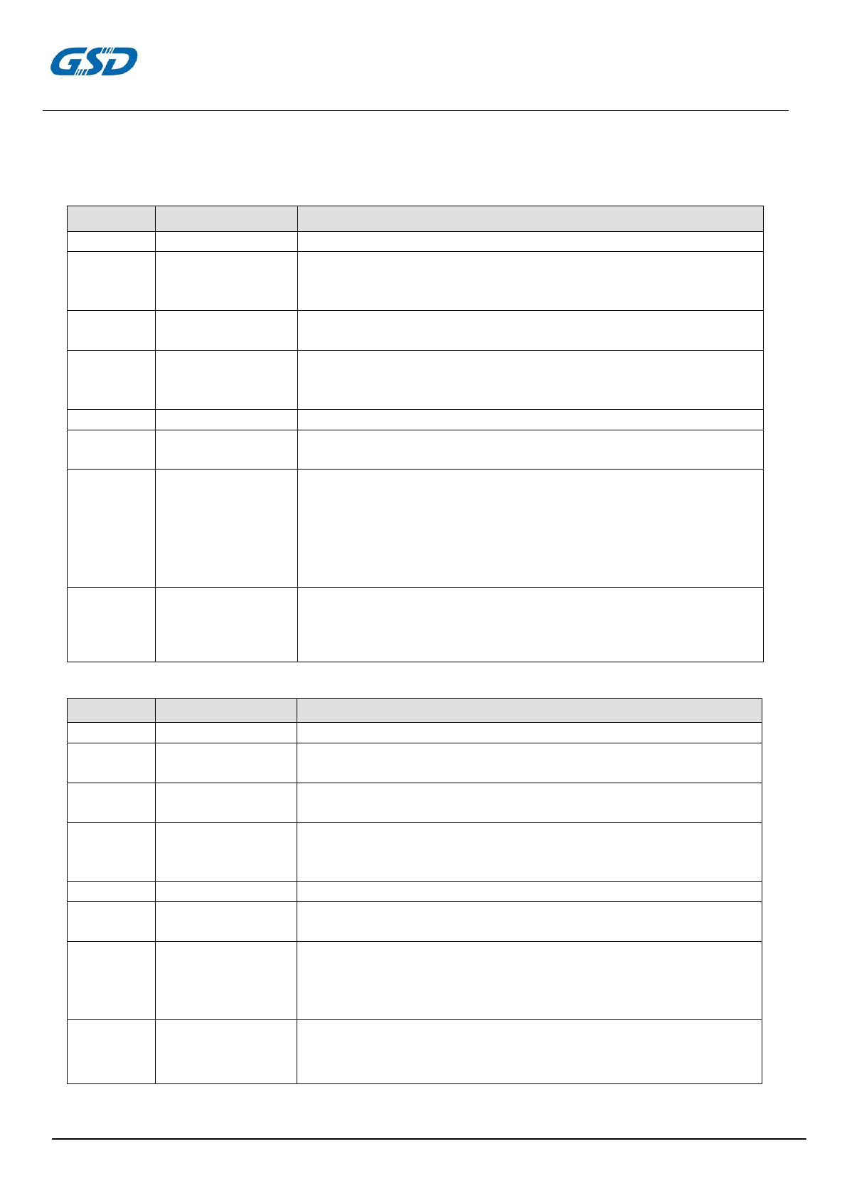
1.2 General Requirements
1.2.1 IEEE 802.11b Section
Feature
Detailed Description
1.2.1.1
Standard
● IEEE 802.11b
1.2.1.2
Radio and
Modulation
Schemes
● DQPSK , DBPSK , DSSS , and CCK
1.2.1.3
Operating
Frequency
● 2400 ~ 2483.5MHz ISM band
1.2.1.4
Channel Numbers
● 11 channels for United States
● 13 channels for Europe Countries
● 14 channels for Japan
1.2.1.5
Data Rate
● 11,5.5,2,and 1Mbps
1.2.1.6
Media Access
Protocol
● CSMA/CA with ACK
1.2.1.7
Transmitter Output
Power at Antenna
Connector
● Typical RF Output Power(tolerance±2dB) at each RF chain,Data
Rate and
at room Temp. 25℃
● +19 dBm at 1Mbps
● +18 dBm at 2Mbps
● +17 dBm at 5.5Mbps
● +16 dBm at 11Mbps
1.2.1.8
Receiver
Sensitivity
at Antenna
Connector
● Typical Sensitivity at Which Frame(1000-byte PDUs)Error
Rate=8%
● -88 dBm at 1Mbps
● -82 dBm for 11Mbps
1.2.2 IEEE 802.11g Section
Feature
Detailed Description
1.2.2.1
Standard
● IEEE 802.11g
1.2.2.2
Radio and
Modulation Type
● QPSK , BPSK , 16QAM ,64QAM with OFDM
1.2.2.3
Operating
Frequency
● 2400 ~ 2483.5MHz ISM band
1.2.2.4
Channel Numbers
● 11 channels for United States
● 13 channels for Europe Countries
● 13 channels for Japan
1.2.2.5
Data Rate
● 6,9,12,18,24,36,48,54Mbps
1.2.2.6
Media Access
Protocol
● CSMA/CA with ACK
1.2.2.7
Transmitter Output
Power at Antenna
Connector
● Typical RF Output Power(tolerance±2dB) at each RF chain,
Data Rate and at roomTemp. 25℃
● +18dBm at 6Mbps
● +14dBm at 54Mbps
1.2.2.8
Receiver
Sensitivity
at Antenna
Connector
● Typical Sensitivity at each RF chain. Frame(1000-byte
PDUs)Error Rate<10% at room Temp 25℃
● -86 dBm at 6Mbps
● -73 dBm at 54Mbps
PRODUCTS SPECIFICATION
PAGE 4 OF 12
WC0DR2611
Version 1.3
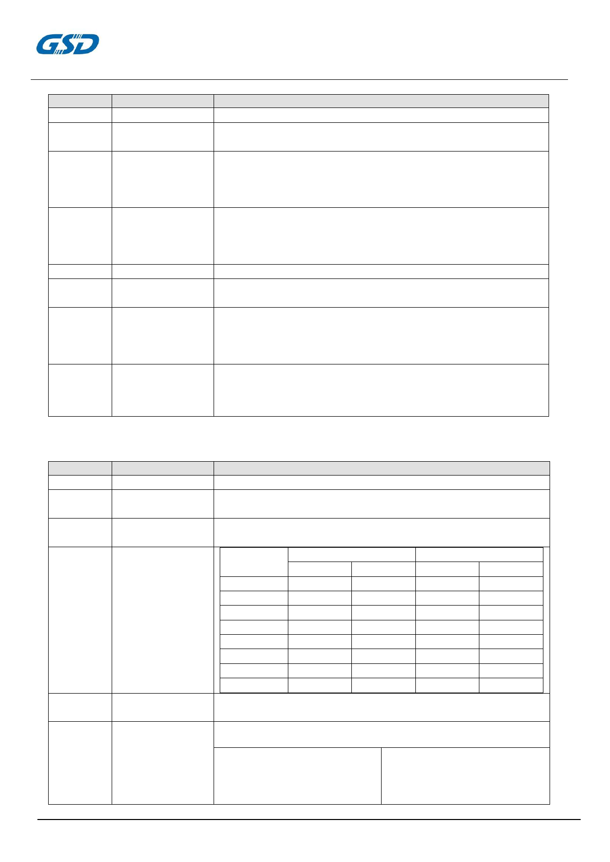
1.2.3 IEEE 802.11a Section
Feature
Detailed Description
1.2.3.1
Standard
● IEEE 802.11a
1.2.1.2
Radio and
Modulation Type
● QPSK , BPSK , 16QAM ,64QAM with OFDM
1.2.3.3
Operating
Frequency
● 5.15~5.25GHz and 5.725~5.825GHz for US and Canada
● 5.15~5.25GHz for Japan
● 5.15~5.25GHz for Europe
● 5.725~5.825GHz for China
1.2.3.4
Channel Numbers
● 12 non-overlapping channels for US and Canada
● 8 non-overlapping channels for Japan
● 19 non-overlapping channels for Europe
● 4 non-overlapping channels for China
1.2.3.5
Data Rate
● 6,9,12,18,24,36,48,54Mbps
1.2.3.6
Media Access
Protocol
● CSMA/CA with ACK
1.2.3.7
Transmitter
Output
Power at Antenna
Connector
● Typical RF Output Power(tolerance±2dB) at each RF chain,
Data Rate and at roomTemp. 25℃
● +18 dBm at 6Mbps
● +14 dBm at 54Mbps
1.2.3.8
Receiver
Sensitivity
at Antenna
Connector
● Typical Sensitivity at each RF chain. Frame(1000-byte
PDUs)Error Rate<10% at room Temp 25℃
● -86 dBm at 6Mbps
● -74 dBm at 54Mbps
1.2.4 IEEE 802.11n Section
Feature
Detailed Description
1.2.4.1
Standard
● IEEE 802.11n
1.2.2.2
Radio and
Modulation Type
● BPSK , QPSK , 16QAM ,64QAM with OFDM
1.2.4.3
Operating
Frequency
● 2.4GHz band:2400 ~ 2483.5MHz
● 5150~5250MHz, 5725~5850MHz
1.2.4.4
Data Rate
MCS
GI=800ns
GI=400ns
20MHz
40MH
20MHz
40MHz
8
13
27
14.4
30
9
26
54
28.9
60
10
39
81
43.3
90
11
52
108
57.8
120
12
78
162
86.7
180
13
104
216
115.6
240
14
117
243
130
170
15
130
270
144.4
300
1.2.4.5
Media Access
Protocol
● CSMA/CA with ACK
1.2.4.6
Transmitter Output
Power at Antenna
Connector
● Typical RF Output Power (tolerance±2dB) at each RF chain,Data Rate
and at roomTemp. 25℃
● 2.4GHz Band/HT20
● 18 dBm at MCS8
● 12 dBm at MCS15
● 2.4GHz Band/HT40
● 18 dBm at MCS8
● 12 dBm at MCS15
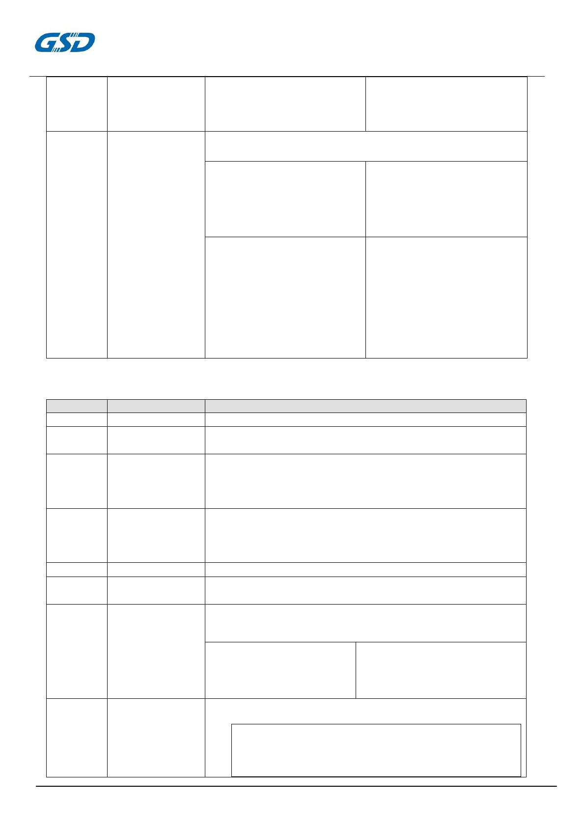
PRODUCTS SPECIFICATION
PAGE 5 OF 12
WC0DR2611
Version 1.3
● 5GHz Band/HT20
● 18 dBm at MCS8
● 12 dBm at MCS15
● 5GHz Band/HT40
● 18 dBm at MCS8
● 12 dBm at MCS15
1.2.4.7
Receiver Sensitivity
at Antenna
Connector
Typical Sensitivity at each RF chain at Which Frame (1000-byte PDUs) Error
Rate=10% and at room Temp. 25℃
2.4GHz Band/HT20
● -86 dBm at MCS8
● -70 dBm at MCS15
2.4GHz Band/HT40
● -83 dBm at MCS8
● -66 dBm at MCS15
5GHz Band/HT20
● -86 dBm at MCS8
● -71 dBm at MCS15
5GHz Band/HT40
● -83 dBm at MCS8
● -67 dBm at MCS15
1.2.5 IEEE 802.11ac Section
Feature
Detailed Description
1.2.5.1
Standard
● IEEE 802.11ac
1.2.5.2
Radio and
Modulation Type
● QPSK , BPSK , 16QAM ,64QAM,256QAM with OFDM
1.2.5.3
Operating
Frequency
● 5.15~5.25GHz and 5.725~5.825GHz for US and Canada
● 5.15~5.25GHz for Japan
● 5.15~5.25GHz for Europe
● 5.725~5.825GHz for China
1.2.5.4
Channel Numbers
● 12 non-overlapping channels for US and Canada
● 8 non-overlapping channels for Japan
● 19 non-overlapping channels for Europe
● 4 non-overlapping channels for China
1.2.5.5
Data Rate
● at most 866.7 Mbps
1.2.5.6
Media Access
Protocol
● CSMA/CA with ACK
1.2.5.7
Transmitter
Output
Power at Antenna
Connector
● Typical RF Output Power(tolerance±2dB) at each RF
chain,
Data Rate and at roomTemp. 25℃
● HT80
● 18 dBm at MCS0
● 12 dBm at MCS8
● 11 dBm at MCS9
1.2.5.8
Receiver
Sensitivity
at Antenna
Connector
● Typical Sensitivity at each RF chain. Frame(1000-byte
PDUs)Error Rate<10% at room Temp 25℃
5GHz Band / HT80
● -58 dBm at MCS9
PRODUCTS SPECIFICATION
PAGE 6 OF 12
WC0DR2611
Version 1.3
2. Electrical and Thermal Characteristics
2.1
Temperature
Limit
Ratings
Parameter
Minimum
Maximum
Units
Storage Temperature
-40
+80
℃
Ambient Operating Temperature
0
60
℃
Junction Temperature
0
125
℃
2.2
General Section
Feature
Detailed Description
2.2.1
Antenna Type
● ANT1: Metal antenna
ANT2: IPEX connector
2.2.2
Operating Voltage
● 5V±10%
2.2.3
Current Consumption
● <900mA
2.2.4
Form Factor and Interface
● High Speed USB2.0 Interface
2.3 Software
Driver
Windows XP/ WinCE/ Vista,/ Win7, Linux, MAC
Security
64/128-bits WEP, WPA, WPA2
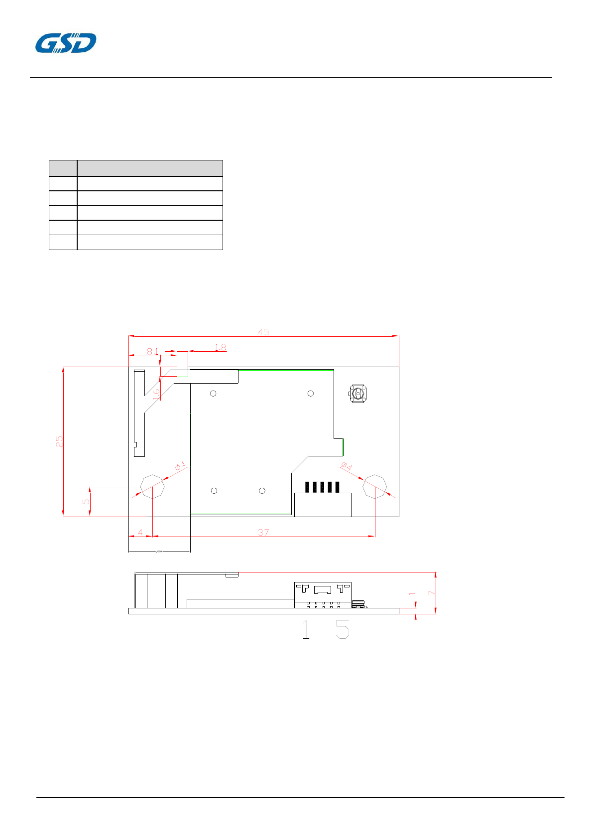
2.4 Mechanical Requirements
Feature
Detailed Description
2.4.1
Length 长度
● 45mm
2.2.2
Width 宽度
● 25mm
2.4.3
High 高度
● 7.0mm(PCB:1mm)
PRODUCTS SPECIFICATION
PAGE 7 OF 12
WC0DR2611
Version 1.3
3. Connector Definition
5-Pin 1.25 mm connector(Horizontal Type)
4 Mechanical Dimensions
ANT1
ANT2
*TOLERANCES ARE +/-0.5mm UNLESS OTHERWISE SPECIFIED
*UNIT:mm
Pin
Symbol
1
POWER_EN
2
GND
3
D+
4
D-
5
VCC(5V)
PRODUCTS SPECIFICATION
PAGE 8 OF 12
WC0DR2611
Version 1.3
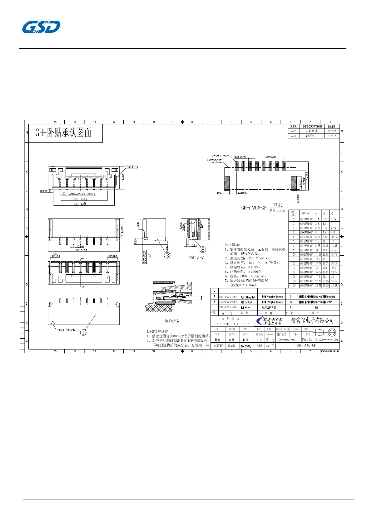
Appendix 1 : SMT connector GH-5AWB-GF
This is the N pin connector which is in common use.You can select 5pin according to
your requirement.

PRODUCTS SPECIFICATION
PAGE 9 OF 12
WC0DR2611
Version 1.3
Appendix 2 : Antenna on board spec
PRODUCTS SPECIFICATION
PAGE 10 OF 12
WC0DR2611
Version 1.3
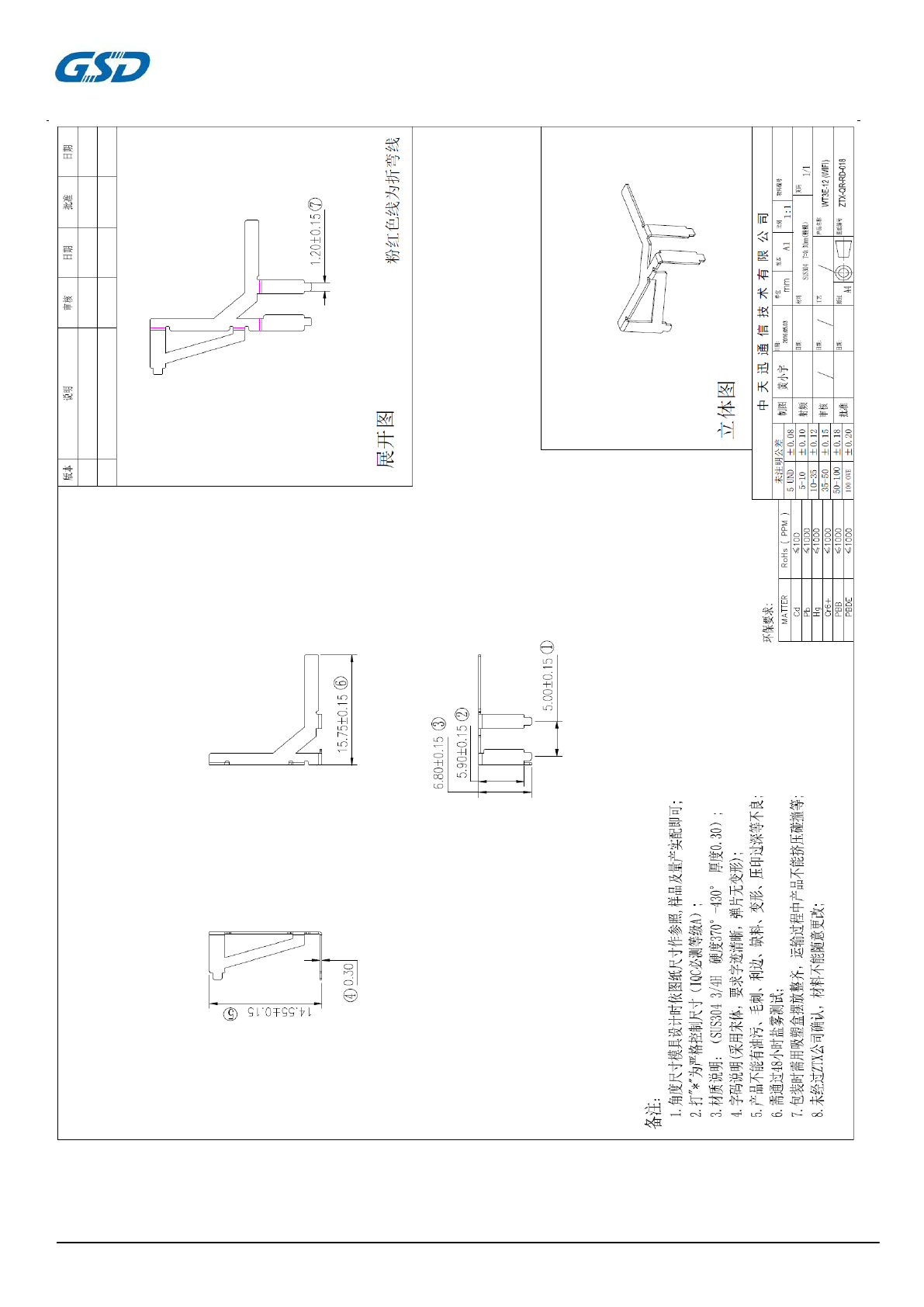
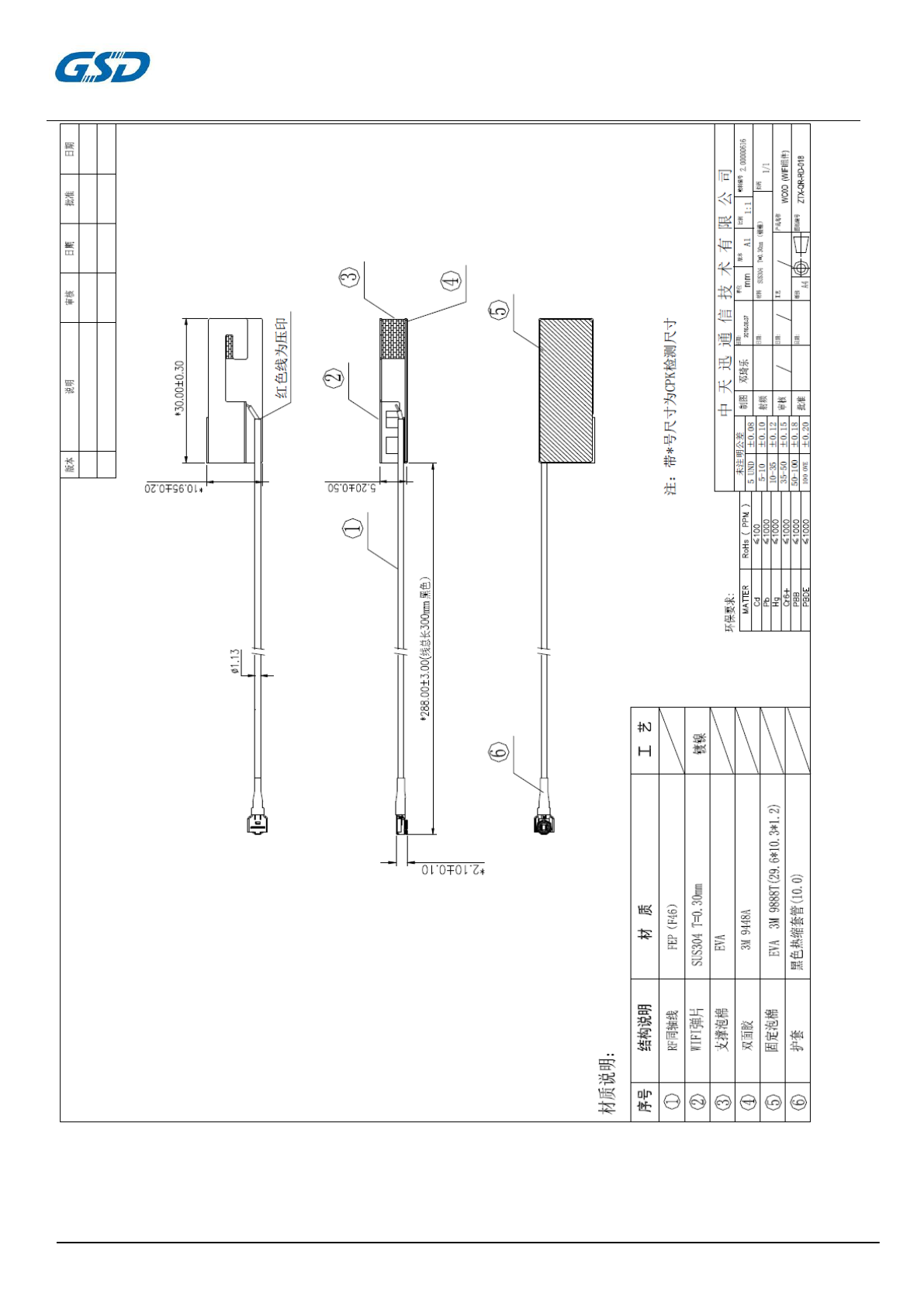
Appendix 3 : Antenna off board spec
PRODUCTS SPECIFICATION
PAGE 11 OF 12
WC0DR2611
Version 1.3

20
IC Radiation Exposure Statement for Canada
This device complies with Industry Canada licence-exempt RSS standard(s). Operation is subject to the following two conditions: (1) this device may not
cause interference, and (2) this device must accept any interference, including interference that may cause undesired operation of the device.
Le présent appareil est conforme aux CNR d'Industrie Canada applicables aux appareils radio exempts de licence. L'exploitation est autorisée aux deux
conditions suivantes : (1) l'appareil ne doit pas produire de brouillage, et (2) l'utilisateur de l'appareil doit accepter tout brouillage radioélectrique subi, même
si le brouillage est susceptible d'en compromettre le fonctionnement.
Under Industry Canada regulations, this radio transmitter may only operate using an antenna of a type and maximum (or lesser) gain approved for the
transmitter by Industry Canada. To reduce potential radio interference to other users, the antenna type and its gain should be so chosen that the equivalent
is otropically radiated power (e.i.r.p.) is not more than that necessary for successful communication.
Conformément à la réglementation d'Industrie Canada, le présent émetteur radio peut
fonctionner avec une antenne d'un type et d'un gain maximal (ou inférieur) approuvé pour l'émetteur par Industrie Canada. Dans le but de réduire les
risques de brouillage radioélectrique à l'intention des autres utilisateurs, il faut choisir le type d'antenne et son gain de sorte que la puissance isotrope
rayonnée équivalente (p.i.r.e.) ne dépasse pas l'intensité nécessaire à l'établissement d'une communication satisfaisante.
User manuals for transmitters equipped with detachable antennas shall also contain the following notice in a conspicuous location:
This radio transmitter (identify the device by certification number, or model number if
Category II) has been approved by Industry Canada to operate with the antenna types listed below with the maximum permissible gain and required
antenna impedance for each antenna type indicated. Antenna types not included in this list, having a gain greater than the maximum gain indicated for that
type, are strictly prohibited for use with this device.
Le présent émetteur radio (identifier le dispositif par son numéro de certification ou son numéro de modèle s'il fait partie du matériel de catégorie I) a été
approuvé par Industrie Canada pour fonctionner avec les types d'antenne énumérés ci-dessous et ayant un gain admissible maximal et l'impédance requise
pour chaque type d'antenne. Les types d'antenne non inclus dans cette liste,ou dont le gain est supérieur au gain maximal indiqué, sont strictement interdits
pour l'exploitation de l'émetteur.
IMPORTANT NOTE:
Radiation Exposure Statement:
This equipment complies with “Industry Canada RSS-102 for radiation exposure limits set forth for an uncontrolled environment”.
This equipment should be installed and operated with minimum distance cm between the radiator and your body.
20

The user manual for local area network devices shall contain instructions related to the restrictions mentioned in the above sections, namely that:
(i) the device for operation in the band 5150–5250 MHz is only for indoor use to reduce the potential for harmful interference to co-channel mobile satellite
systems;
(iii) for devices with detachable antenna(s), the maximum antenna gain permitted for devices in the band 5725-5850 MHz shall be such that the equipment
still complies with the e.i.r.p. limits specified for point-to-point and non-point-to-point operation as appropriate; and
(iv) the worst-case tilt angle(s) necessary to remain compliant with the e.i.r.p. elevation mask requirement set forth shall be clearly indicated.
Le guide d'utilisation des dispositifs pour réseaux locaux doit inclure des instructions précises sur les restrictions susmentionnées, notamment
:
(I) l'appareil pour fonctionner dans la bande 5150-5250 MHz est réservé à une utilisation intérieure pour réduire le potentiel d'interférences nuisibles à la co-
canal avec les systèmes mobiles par satellite;
(Iii) pour les appareils avec antenne (s) détachable, le gain d'antenne maximal autorisé pour les appareils à la bande 5725-5850 MHz doit être telle que
l'équipement satisfait encore la pire limites spécifiées pour le point-à-point et non point-à-point de l'opération, le cas échéant; et
(Iv) l'angle d'inclinaison du pire (s) nécessaire pour rester conforme à la pire masque d'élévation condition énoncée doit être clairement indiqué.
installed such that 20cm may be maintained between the antenna and users. The final en
Host Product Labelling Requirements:
This transmitter module is authorization only for use in device where the antenna may be d
product must be labeled in a visible area with the following “Contains IC: 12290A-WC0DR2611”
"Contains FCC ID: 2AC23-WC0DR2611
Federal Communications Commission (FCC) Interference
Statement
This equipment has been tested and found to comply with the limits for
a Class B digital device, pursuant to Part 15 of the FCC Rules.
These limits are designed to provide reasonable protection against
harmful interference in a residential installation. This equipment
generate, uses and can radiate radio frequency energy and, if not
installed and used in accordance with the instructions, may cause
harmful interference to radio communications.
However, there is no guarantee that interference will not occur in a
particular installation. If this equipment does cause harmful interference
to radio or television reception, which can be determined by turning the
equipment off and on, the user is encouraged to try to correct the
interference by one of the following measures:
Reorient or relocate the receiving antenna.
Increase the separation between the equipment and receiver.
Connect the equipment into an outlet on a circuit different from that
to which the receiver is connected.
Consult the dealer or an experienced radio/TV technician for help.
This device complies with Part 15 of the FCC Rules. Operation is
subject to the following two conditions:
(1) This device may not cause harmful interference, and (2) this device
must accept any interference received, including interference that may
cause undesired operation.
FCC Caution: Any changes or modifications not expressly approved by
the party responsible for compliance could void the user’s authority to
operate this equipment.
RF exposure warning
This equipment complies with FCC radiation exposure limits set forth
for an uncontrolled environment.
This equipment must not be collocated or operating in conjunction with
any other antenna or transmitter.