HUIZHOU GAOSHENGDA TECHNOLOGY WT31M2311A WIFI Module User Manual Users manual
Hui Zhou Gaoshengda Technology Co.,LTD WIFI Module Users manual
Contents
- 1. Users manual
- 2. Users manual-r2
- 3. Users manual-r1
Users manual
USER MANUAL
(FOR INTEGRATION)
PRODUCTS SPECIFICATION
PAGE 1 OF 11
Version1.0
WT31M2311A/A1/A2/A3
IEEE
802.11 a/b/g/n
2T/2R Dual Band
USB Module
Integrated Bluetooth 2.1/3.0/4.0LE
Model Number:
WT31M2311A/A1/A2/A3
(
MediaTek :MT7632TUN
)
客户认可
Custom Approval Section
Custom Name
Department
Approval Date:
拟制
DESIGN
审核
CHECK
批准
APPROVAL
PRODUCTS SPECIFICATION
PAGE 2 OF 11
WT31M2311A/A1/A2/A3
Version1.0
Document revision history
Revision Date Approved by Remarks
Version 1.0 2016-10-20 Draft

PRODUCTS SPECIFICATION
PAGE 3 OF 11
WT31M2311A/A1/A2/A3
Version1.0
1. General Description
This document is to specify the product requirements for 802.11a/b/g/n and BT combo module. This
module is based on MediaTek MT7632TUN single chip that complied with IEEE 802.11b, IEEE 802.11g, IEEE
802.11n, IEEE 802.11a standard from 2.4~2.5GHz and 5.15GHz ~ 5.35GHz , and it can be used to provide
up to 11Mbps for IEEE 802.11b, 54Mbps for IEEE 802.11g, 300Mbps for 802.11n . The module complied with
Bluetooth 2.1 with EDR, v3.0, and v4.0 with BLE.
With seamless roaming, fully interoperability and advanced security with WEP standard, 802.11a/b/g/n
combo module offers absolute interoperability with different vendors’ 802.11b, 802.11g, and 802.11n Access
Points through the wireless LAN.
2. Features
Compatible with IEEE 802.11a standard to provide wireless 54Mbps data rate
Compatible with IEEE 802.11b standard to provide wireless 11Mbps data rate
Compatible with IEEE 802.11g standard to provide wireless 54Mbps data rate
Compatible with IEEE 802.11n standard to provide wireless 300Mbps data rate
Operation at 2.4~2.5GHz and 5.15~5.825GHz frequency band to meet worldwide regulations
Compatible with Bluetooth 2.1 with EDR, v3.0 and v4.0 with BLE.
Maximum reliability, throughput and connectivity with automatic data rate switching
Supports infrastructure networks via Access Point and ad-hoc network via peer-to-peer communication
High speed USB 2.0 interface
RoHS compliant
PRODUCTS SPECIFICATION
PAGE 4 OF 11
WT31M2311A/A1/A2/A3
Version1.0
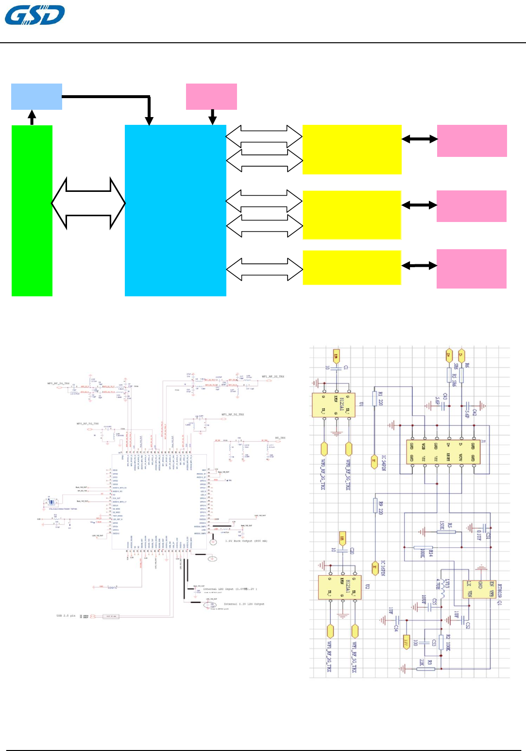
3. Application Diagrams
3.1 Functional Block Diagram
3.2 Schematic
USB2.0 Interface
MT7632TUN
Crystal
40
MHz
Interface
Sig
nals
Diplexer
Antenna 1
2.4G TX1 / RX1
5G TX1 / RX1
Diplexer
Antenna 0
2.4G TX0 / RX0
5G TX0 / RX0
Low Pass
Filter
BT
Antenna
BT TX/RX
DC/DC
5V
3.3V
MT7632TUN
PRODUCTS SPECIFICATION
PAGE 5 OF 11
WT31M2311A/A1/A2/A3
Version1.0
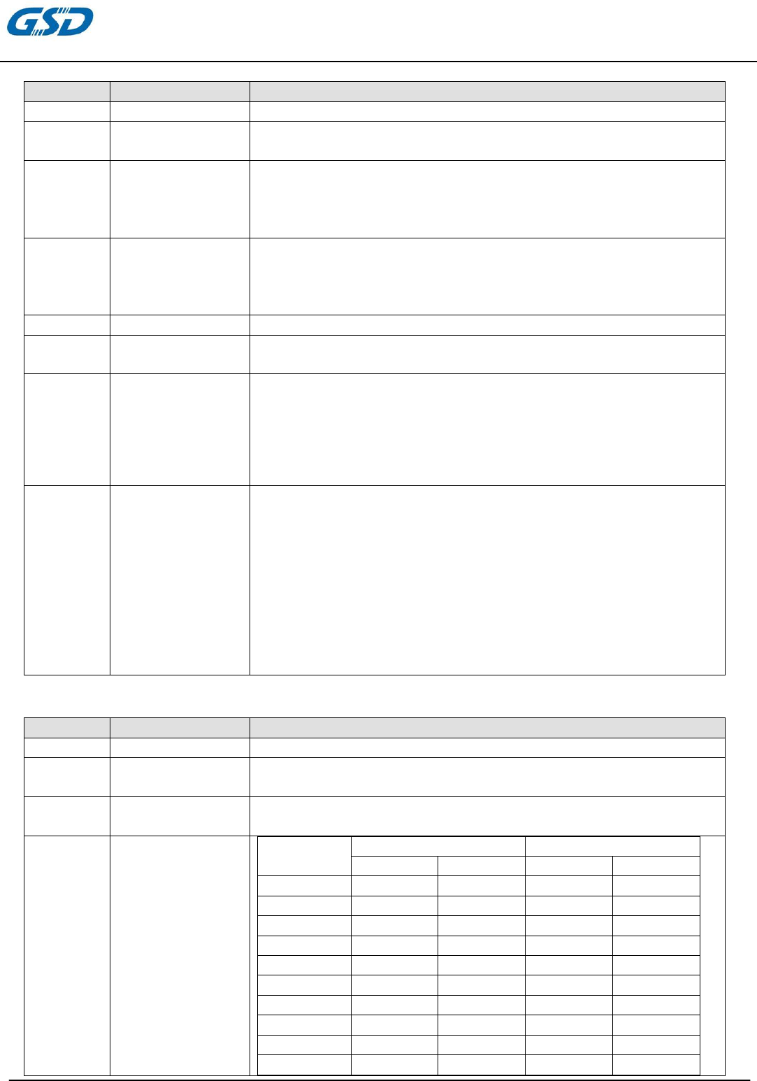
3.3 General Requirements
3.3.1 IEEE 802.11b Section
#
Feature
Detailed Description
3.3.1.1 Standard ● IEEE 802.11b
3.3.1.2
Radio and
Modulation
Schemes
● CCK(DQPSK , DBPSK , DSSS)
3.3.1.3 Operating
Freq
uenc
y
● 2400 ~ 2483.5 MHz ISM band
3.3.1.4 Channel Numbers
● 11 channels for United States
● 13 channels for Europe Countries
● 14 channels for J
ap
an
3.3.1.5 Data Rate ● 11
,5.5,2,and 1Mbp
s
3.3.1.6 Media Access
Protocol
● CSMA/CA with ACK
3.3.1.7
Transmitter Output
Power at Antenna
Connector
● Typical RF Output Power at each RF chain,Data Rate and
at room Temp. 25degree C
● 17±1.5 dBm at 1,2,5.5,11Mbps
3.3.1.8
Receiver
Sensitivity
at Antenna
Connector
● Typical Sensitivity at Which Frame(1000-byte PDUs)Error
Rate=8%
● -90 dBm at 1Mbps
● -86 dBm for 11Mbps
3.3.2 IEEE 802.11g Section
#
Feature
Detailed Description
3.3.2.1 Standard ● IEEE 802
.11g
3.3.2.2 Radio and
Modu
lation Typ
e
● QPSK , BPSK , 16QAM ,64QAM with OFDM
3.3.3.3 Operating
Freq
uenc
y
● 2400 ~ 2483.5MHz ISM band
3.3.3.4 Channel Numbers
● 11 channels for United States
● 13 channels for Europe Countries
● 13 channels for J
ap
an
3.3.2.5 Data Rate ● 6,9,12,18,24,36,48,54
Mbps
3.3.2.6 Media Access
Protocol
● CSMA/CA with ACK
3.3.2.7
Transmitter Output
Power at Antenna
Connector
● Typical RF Output Power at each RF chain,Data Rate and at
roomTemp. 25degree C
● 16±1.5 dBm at 6,9Mbps
● 16±1.5 dBm at 12,18Mbps
● 15±1.5 dBm at 24,36Mbps
● 15±1.5 dBm at 48,54
Mbps
3.3.2.8
Receiver
Sensitivity
at Antenna
Connector
● Typical Sensitivity at each RF chain. Frame(1000-byte
PDUs)Error Rate<10% at room Temp 25 degree C
● -92 dBm at 6Mbps
● -90 dBm at 9Mbps
● -88 dBm at 12Mbps
● -86 dBm at 18Mbps
● -82 dBm at 24Mbps
● -80 dBm at 36Mbps
● -76 dBm at 48Mbps
● -75 dBm
at 54Mbp
s
PRODUCTS SPECIFICATION
PAGE 6 OF 11
WT31M2311A/A1/A2/A3
Version1.0
3.3.3 IEEE 802.11a Section
#
Feature
Detailed Description
3.3.3.1 Standard ● IEEE 802.11a
3.3.3.2 Radio and
Modu
lation Typ
e
● QPSK , BPSK , 16QAM ,64QAM with OFDM
3.3.3.3 Operating
Frequency
● 5.15~5.35GHz、5.47~5.825GHz for US and Canada
● 5.15~5.35GHz and 5.47~5.725GHz for Japan
● 5.15~5.35GHz and 5.47~5.725GHz for Europe
● 5.15~5.35GHz and 5.725~5.825GHz for China
3.3.3.4 Channel Numbers
● 21 non-overlapping channels for US and Canada
● 8 non-overlapping channels for Japan
● 19 non-overlapping channels for Europe
● 16 non-ove
rlap
pin
g
channels for China
3.3.3.5 Data Rate ● 6,9,12,18,24,36,48,54
Mbps
3.3.3.6 Media Access
Protocol
● CSMA/CA with ACK
3.3.3.7
Transmitter Output
Power at Antenna
Connector
● Typical RF Output Power at each RF chain,Data Rate and at
roomTemp. 25degree C
● 16±1.5dBm at 6,9Mbps
● 16±1.5dBm m at 12,18Mbps
● 15±1.5dBm at 24,36Mbps
● 15±1.5dBm at 48,54Mb
ps
3.3.3.8
Receiver
Sensitivity
at Antenna
Connector
● Typical Sensitivity at each RF chain. Frame(1000-byte
PDUs)Error Rate<10% at room Temp 25 degree C
● -90 dBm at 6Mbps
● -88 dBm at 9Mbps
● -87 dBm at 12Mbps
● -85 dBm at 18Mbps
● -82 dBm at 24Mbps
● -80 dBm at 36Mbps
● -75 dBm at 48Mbps
● -73 dBm at 54Mbps
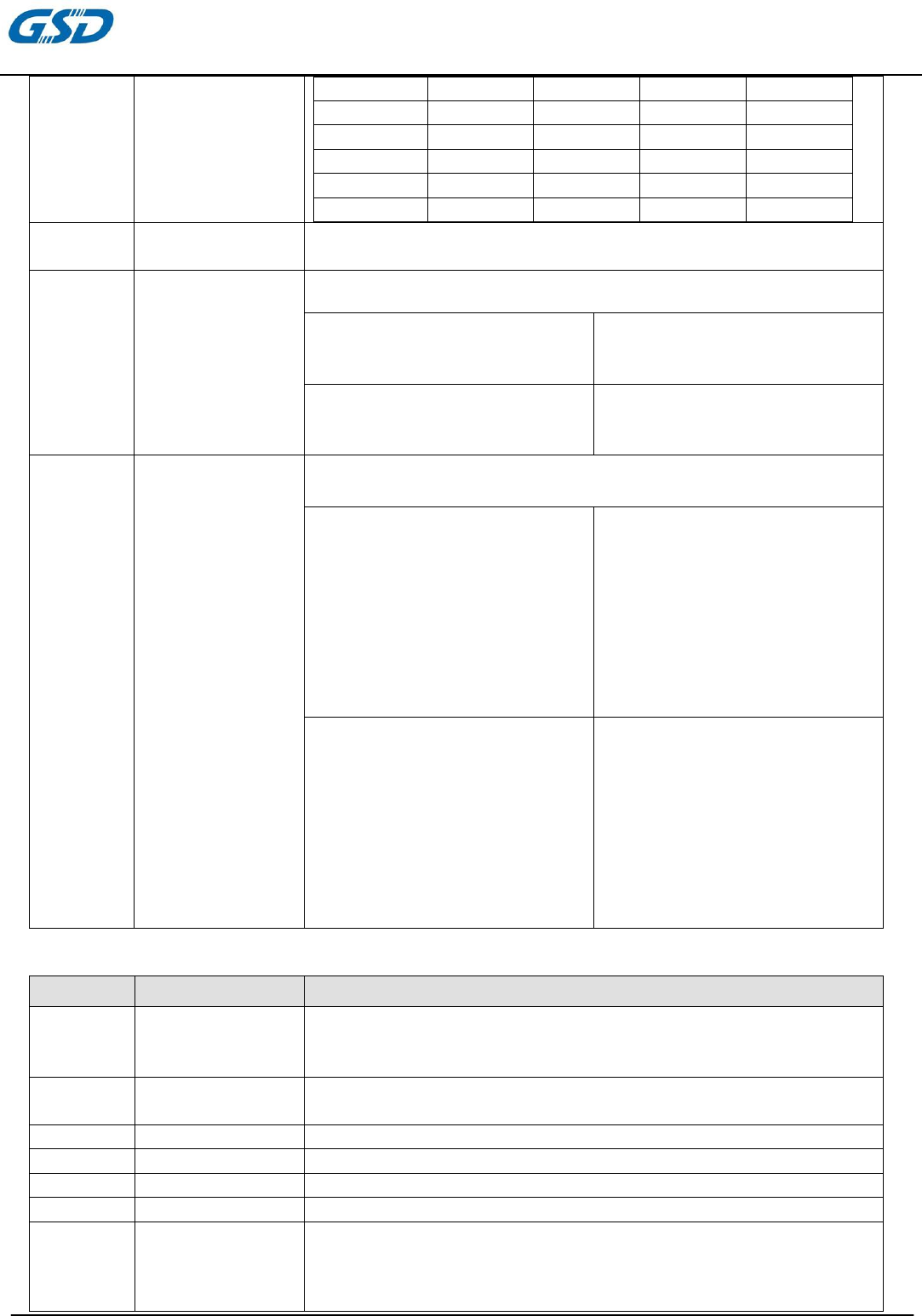
3.3.4 IEEE 802.11n Section
#
Feature
Detailed Description
3.3.4.1 Standard ● IEEE 802.11n
3.3.4.2 Radio and
Modu
lation Typ
e ● BPSK , QPSK , 16QAM ,64QAM with OFDM
3.3.4.3 Operating
Freq
uenc
y
● 2.4GHz band:2400 ~ 2483.5MHz ISM band
● 5GHz and:5150 ~ 5825MHZ
3.3.4.4 Data Rate
MCS GI=800ns GI=400ns
20MHz 40MH 20MHz 40MHz
0 6.5 13.5 7.2 15
1 13 27 14.4 30
2 19.5 40.5 21.7 45
3 26 54 28.9 60
4 39 81 43.3 90
5 52 108 57.8 120
6 58.5 121.5 65.0 135
7 65 135 72.2 150
8 13 27 14.444 30
9 26 54 28.889 60
PRODUCTS SPECIFICATION
PAGE 7 OF 11
WT31M2311A/A1/A2/A3
Version1.0
10 39 81 43.333 90
11 52 108 57.778 120
12 78 162 86.667 180
13 104 216 115.556 240
14 117 243 130.000 170
15 130 270 144.444 300
3.3.4.5 Media Access
Protocol ● CSMA/CA with ACK
3.3.4.6
Transmitter Output
Power at Antenna
Connector
● Typical RF Output Power at each RF chain,Data Rate and at
ro
omTemp. 25 deg
ree C
● 2.4GHz Band/HT20
15~14±1.5 dBm at MCS0~7
14±1.5 dBm at MCS8~15
● 2.4GHz Band/HT40
15~14±1.5 dBm at MCS0~7
14±1.5 dBm at MCS8~15
● 5GHz Band/HT20
15~14±1.5 dBm at MCS0~7
14±1.5 dBm at MCS8~15
● 5GHz Band/HT40
15~14±1.5 dBm at MCS0~7
14±1.5 dBm at MCS8~15
3.3.4.7
Receiver
Sensitivity
at Antenna
Connector
Typical Sensitivity at each RF chain at Which Frame (1000-byte
PDUs) Error Rate=10% and at room Temp.25 degree.
2.4GHz Band/HT20
● -90dBm at MCS0/8
● -87dBm at MCS1/9
● -85dBm at MCS2/10
● -82dBm at MCS3/11
● -78dBm at MCS4/12
● -76dBm at MCS5/13
● -75dBm at MCS6/14
● -74dBm at MCS7/15
2.4GHz Band/HT40
● -89dBm at MCS0/8
● -86dBm at MCS1/9
● -84dBm at MCS2/10
● -81dBm at MCS3/11
● -77dBm at MCS4/12
● -73dBm at MCS5/13
● -72dBm at MCS6/14
● -71dBm at MCS7/15
5GHz Band/HT20
● -90dBm at MCS0/8
● -87dBm at MCS1/9
● -85dBm at MCS2/10
● -82dBm at MCS3/11
● -78dBm at MCS4/12
● -74dBm at MCS5/13
● -73dBm at MCS6/14
● -72dBm at MCS7/15
5GHz Band/HT40
● -87dBm at MCS0/8
● -84dBm at MCS1/9
● -82dBm at MCS2/10
● -79dBm at MCS3/11
● -75dBm at MCS4/12
● -72dBm at MCS5/13
● -70dBm at MCS6/14
● -68dBm at MCS7/15
3.3.5 Bluetooth Section
#
Feature
Detailed Description
3.3.5.1
Radio and
Modulation
Schemes
● FHSS,GFSK,DPSK,DQPSK
3.3.5.2 Operating
Freq
uenc
y
● 2402 ~ 2480 MHz in the ISM band
3.3.5.3 Channel Numbers ● 79 channels
3.3.5.4
Symbo
l Rate ● 1、2 an
d 3 Mbps
3.3.5.5 Carrie
r Spacing
● 1.0MHZ
3.3.5.6 Antenna reference ● Small antenna with 0-2 db
i peak
ga
in
3.3.5.7
Transmitter Output
Power at Antenna
Connector
● Typical RF Output Power (tolerance +/-1.5dB) at each RF chain,
Data Rate and at room Temp. 25degree C
● -6≤Output Power≤+10 dBm ;CLASS 1.5 Device
PRODUCTS SPECIFICATION
PAGE 8 OF 11
WT31M2311A/A1/A2/A3
Version1.0
Note: The maximum power setting will vary according to individual country
regulations.
3.3.5.8
Receiver
Sensitivity
at Antenna
Connector
● Sensitivity @ BER=0.1% for GFSK (1Mbps) Typical: -86dBm
● Sensitivity @ BER=0.01% for π/4-DQPSK (2Mbps) Typical:-86dBm
● Sensitivity @ BER=0.01% for 8DPSK (3Mbps) Typical:-80dBm
3.3.5.9
Sensitive
@BER=0.01% FOR
8DQPSK(3Mbps)
Maximum input level
● GFSK(1Mbps) -20dBm
● π/4-DQPSK(2Mbps) -20dBm
● 8DQPSK(3Mbps) -20dBm
3.3.5.9 Carrier Frequency
Stablity
● DH1: ±25 kHz
● DH3/DH5: ±40 kHz
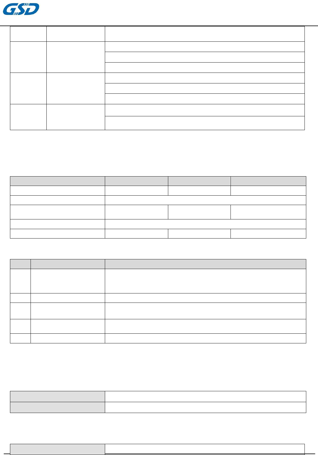
4. Thermal and Electrical Characteristics
4.1 Temperature Limit Ratings
Parameter
Minimum
Maximum
Units
Storage
Temperature
-40
+80
℃
Storage Relative Humidity
5-95%(non-condensing)
Ambient
Operating
Tem
pe
rature
0
+60
℃
Operating Relative Humidity 5-90%(non-condensing)
Junction
Temperature
0
+125
℃
4.2 General Section
#
Feature
Detailed Description
4.2.1 Antenna Type ● PIFA antenna (WiFi ) (see appendix1)
● I-PEX connector (BT) (see appendix2)
● PIFA antenna
(
BT
)
(see ap
pe
ndix3
)
4.2.2 Operating Voltage ● 5.0V±10%
4.2.3 Current Consumption ● 900 mA at continuous transmit mode
● 360 mA at receive mode w/o re
ceiving
pack
et
4.2.4 Form Factor and
Interface
● High Speed USB2.0 Interface
4.2.5 Connector ● 9 pin connector (see appendix4)
5. Software
5.1 DRIVER Information
Driver Win7, Linux, MAC
Security 64/128-bits WEP, WPA, WPA2
5.2 EEPROM Information
BT
Vendor ID 0x0E8D
PRODUCTS SPECIFICATION
PAGE 9 OF 11
WT31M2311A/A1/A2/A3
Version1.0
Product ID 0x76A1
WiFi
Reg Domain
Worldwide 2.4G/5G
Read from registry;Control by driver
Offset 0x38 for 5G:0xFF
Offset 0x39 for 2.4G:0xFF
Vendor ID 0x0E8D
Product ID 0x76A1
6. Mechanical Characteristics
6.1 Mechanical Requirements
#
Feature
Detail
ed Description
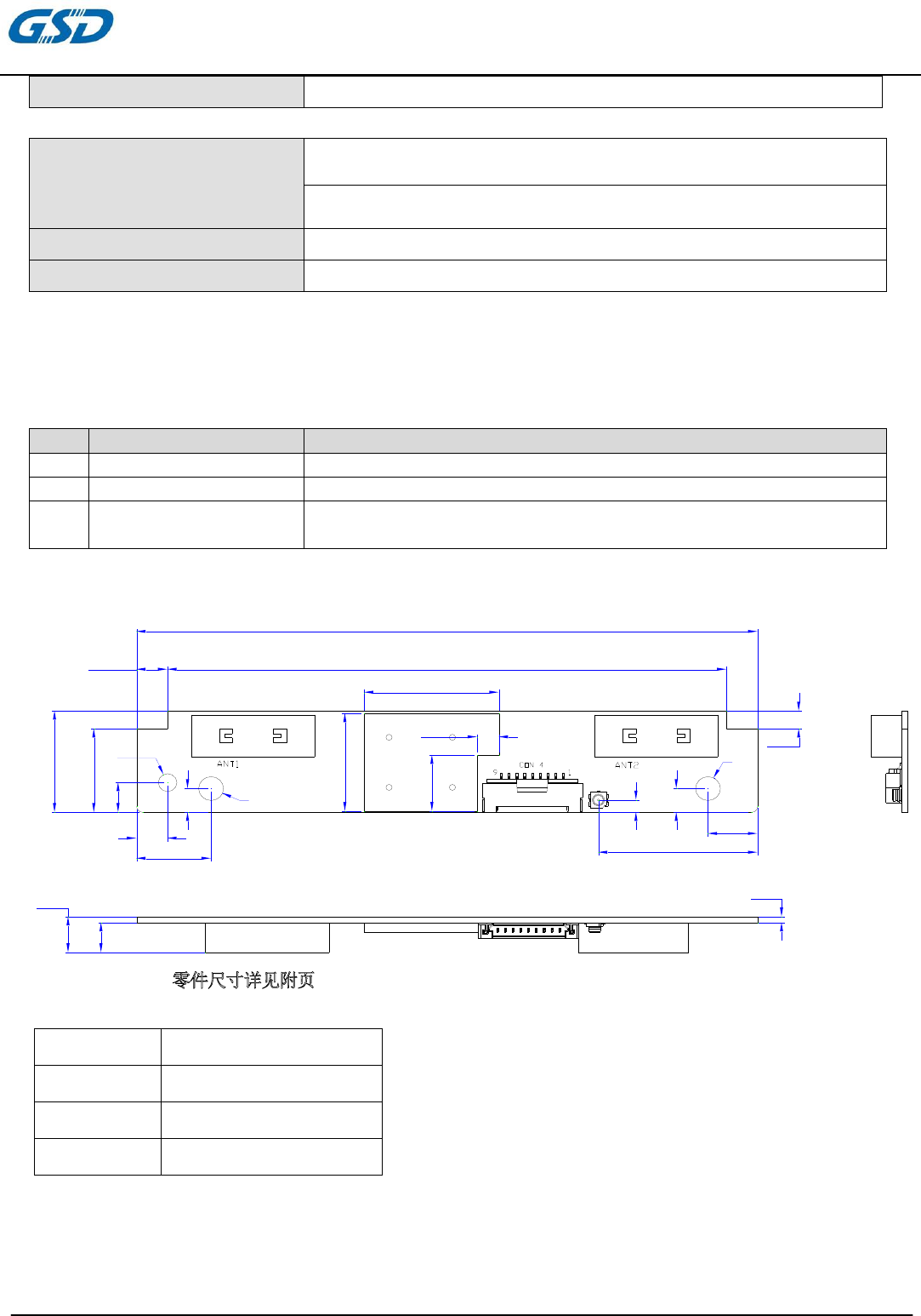
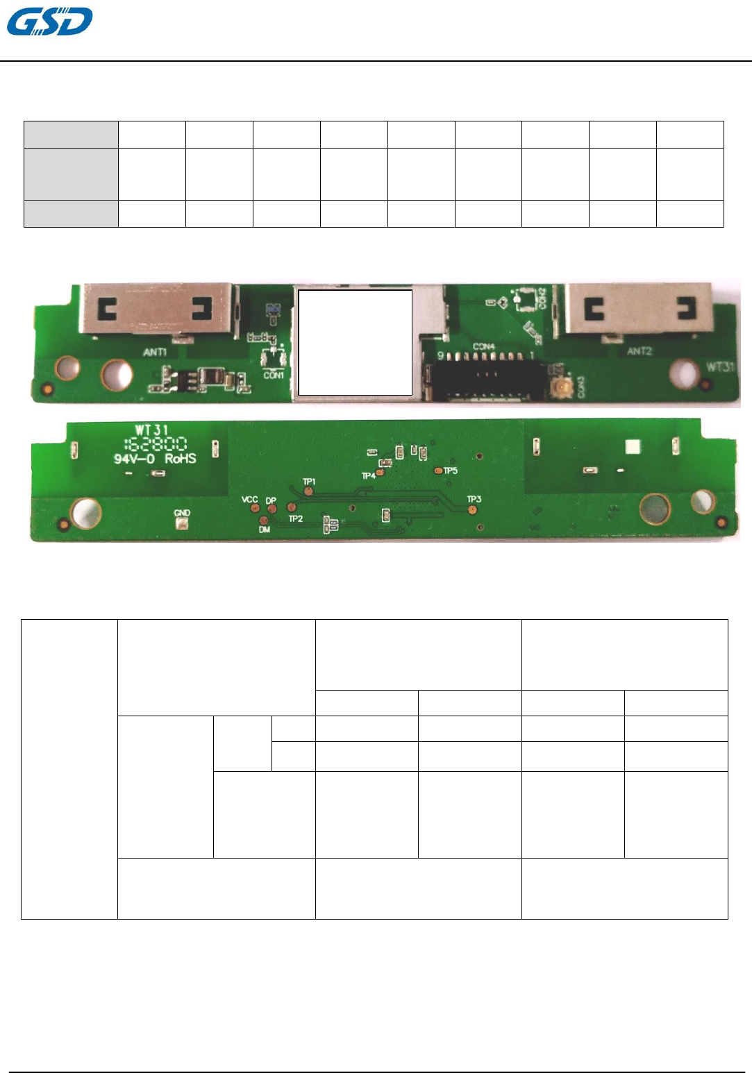
6.1.1 Length ● 100mm
6.1.2 Width ● 17mm
6.1.3 Height ● 1.0mm(PCB)
● MAX:8mm
6.2
Mechanical Dimensions
尺寸误差范围:零件尺寸详见附页
Size error range: parts size as shown in the attachment
DIM(MM) Tolerance(MM)
0-5 ±0.15
5-10 ±0.20
10-50 ±0.30
90.00
100.00
5.00
17.00
14.00
3.00
5
4
12
R1.50
4
8
6.00
5.00
1.00
R2.00
R2.00
21.70
16.40
3.50
9.40
25.65
2.10
5
PRODUCTS SPECIFICATION
PAGE 10 OF 11
WT31M2311A/A1/A2/A3
Version1.0
6.3
Pin Description
1.25-9 Pin connector
6.4
Product Pictiure
6.5
Power consumption
Remarks: Strongly recommend TV platform has to fulfill output current at least 1A
测试方法:使用MTK Tools,版本号V1.0.3.0,打出Module 所设定的最大功率,量
测耗电量。
Test method: using the MTK Tools, version number V1.0.3.0, hit the Module
maximum power set, the measured power consumption.
Pin
1 2 3 4 5 6 7 8 9
Definition VCC DM DP GND WiFi_
Reset
WiFi_I
RQn
WiFi_I
RQn
GND VCC
5V USB D- USB D+ WOLAN WOBT 5V
Power
consump
tion
mode
正常使用 MAX 值
Normal use MAX
value
瞬间启动 MAX 值
Instant on MAX value
2.4G 5G 2.4G 5G
正常使用
(联网跑
传输率)
Normal
use
(network
run rate)
WiFi TX 470mA 570mA 700mA 940mA
RX 150mA 160mA 250mA 260mA
BT 160mA 200mA
Idle Mode
(联网不跑传输率)Don't
run rate
(networking)
160mA
Lable
PRODUCTS SPECIFICATION
PAGE 11 OF 11
WT31M2311A/A1/A2/A3
Version1.0
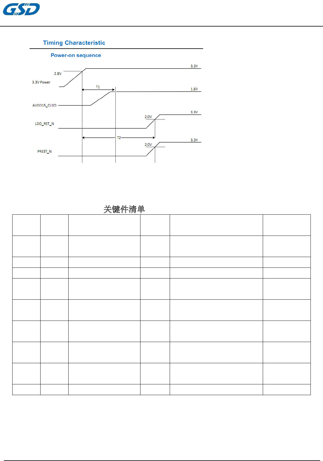
6.6
Power on sequence timing
T1:max 1ms
T2:>1ms
7. BOM(
Part List
)
关键件清单Key-module listing
序号
number
位号no. 名称name 数量
PCS
商标/制造商
trademark/manufacturers
使用状态Using
a state
1 集成电路integrated
circuit
1 MTK 在用In the use
2 WiFi天线WiFi antenna 2 ---- 在用In the use
3 印制板PCB 1 ---- 在用In the use
4 贴片电容器patch
capacitor
57 ---- 在用In the use
5 贴片电感器patch
capacitor
19 ---- 在用In the use
6 贴片电阻器SMD
resistor
9 ---- 在用In the use
7 贴片插座(镀金) SMT
socket (plating)
1 ---- 在用In the use
8 晶体振荡器Crystal
oscillator
1 ---- 在用In the use
9 BT天线BT antenna 1 ---- 在用In the use
FCC Statement
This equipment has been tested and found to comply with the limits for a Class
B digital device, pursuant to part 15 of the FCC rules. These limits are
designed to provide reasonable protection against harmful interference in a
residential installation. This equipment generates, uses and can radiate radio
frequency energy and, if not installed and used in accordance with the
instructions, may cause harmful interference to radio communications.
However, there is no guarantee that interference will not occur in a particular
installation. If this equipment does cause harmful interference to radio or
television reception, which can be determined by turning the equipment off and
on, the user is encouraged to try to correct the interference by one or more of
the following measures:
-Reorient or relocate the receiving antenna.
-Increase the separation between the equipment and receiver.
-Connect the equipment into an outlet on a circuit different from that to which
the receiver is connected.
-Consult the dealer or an experienced radio/TV technician for help.
To assure continued compliance, any changes or modifications not expressly
approved by the party.
Responsible for compliance could void the user’s authority to operate this
equipment. (Example- use only shielded interface cables when connecting to
computer or peripheral devices).
This equipment complies with Part 15 of the FCC Rules. Operation is subject
to the following two conditions:
(1) This device may not cause harmful interference, and
(2) This device must accept any interference received, including interference
that may cause undesired operation.
FCC Radiation Exposure Statement:
The equipment complies with FCC Radiation exposure limits set forth for
uncontrolled enviroment. This equipment should be installed and operated with
minimum distance 20cm between the radiator and your body.
.
FCC Important Notes:
(1)
FCC Statement
This equipment complies with FCC RF radiation exposure limits set forth for an uncontrolled environment. This
transmitter
must not be co-located or operating in conjunction with any other antenna or transmitter.
This equipment complies with Part 15 of the FCC Rules. Operation is subject to the following two conditions:
(1) This device may not cause harmful interference, and
(2) This device must accept any interference received, including interference that may cause undesired operation.
The devices must be installed and used in strict accordance with the manufacturer’s instructions as described in
the user documentation that comes with the product. Modular could be only used in mobile or fix device, and
could not be used in any portable device.
Caution!
The manufacturer is not responsible for any radio or TV interference caused by unauthorized modifications to this
equipment. Such modifications could void the user authority to operate the equipment.
FCC Radiation Exposure Statement
This equipment complies with FCC radiation exposure limits set forth for an uncontrolled environment. This
equipment should be installed and operated with minimum distance 20cm between the radiator and your body.
This device and it’s antennas(s) must not be co-located or operating in conjunction with any other antenna or
transmitter except in accordance with FCC multi-transmitter product procedures.
(2)
Co-location Warning:
This device and its antenna(s) must not be co-located or operating in conjunction with any other antenna or
transmitter.
(3)
OEM integration instructions:
This device is intended only for OEM integrators under the following conditions:
The transmitter module may not be co-located with any other transmitter or antenna. The module shall be only
used with the integral antenna(s) that has been originally tested and certified with this module.
As long as 3 conditions above are met, further transmitter test will not be required. However, the OEM integrator
is still responsible for testing their end-product for any additional compliance requirements required with this
module installed (for example, digital device emissions, PC peripheral requirements, etc.).
(4)
Validity of using the module certification:
In the event that these conditions cannot be met (for example certain laptop configurations or co-location with
another transmitter), then the FCC authorization for this module in combination with the host equipment is no
longer considered valid and the FCC ID of the module cannot be used on the final product. In these
circumstances, the OEM integrator will be responsible for re-evaluating the end product (including the
transmitter) and obtaining a separate FCC authorization.
(5)
End product labeling:
The final end product must be labeled in a visible area with the following:
“Contains Transmitter Module FCC ID: 2AC23-WT31M2311A”.
(6)
Information that must be placed in the end user manual:
The OEM integrator has to be aware not to provide information to the end user regarding how to install or remove
this RF module in the user's manual of the end product which integrates this module. The end user manual shall
include all required regulatory information/warning as show in this manual.

FCC Caution: Any changes or modifications not expressly approved by the party responsible for compliance
could void the user’s authority to operate this equipment.
IEEE 802.11b or 802.11g operation of this product in the USA is firmware-limited to channels 1 through 11.
The device for the band 5150-5250 MHz is only for indoor usage to reduce the potential for harmful interference
to co-channel mobile satellite systems.
IC Statement
- English: "
This device complies with Industry Canada licence-exempt RSS standard(s). Operation is subject
to the following two conditions: (1) this device may not cause interference, and (2) this device must accept any
interference, including interference that may cause undesired operation of the device."
The final end product must be labeled in a visible area with the following:
“Contains Transmitter Module IC: 12290A-WT31M2311A”.
- French:"
Le présent appareil est conforme aux CNR d'Industrie Canada applicables aux appareils radio
exempts de licence. L'exploitation est autorisée aux deux conditions suivantes : (1) l'appareil ne
doit pas produire de brouillage, et (2) l'utilisateur de l'appareil doit accepter tout brouillage
radioélectrique subi, même si le brouillage est susceptible d'en compromettre le fonctionnement."
The final end product must be labeled in a visible area with the following:
“Contains Transmitter Module IC: 12290A-WT31M2311A”.
Approved antennas (do not use any other antenna than listed below):
For Wi-Fi, onboard PIFA Antenna 1:
Max. Gain: 2400-2483.5: 3 dBi
Max. Gain: 5150~5250, 5725~5850: 2.54 dBi
External Antenna 1: none
For Wi-Fi, onboard PIFA Antenna 2
Gain: 2400-2483.5: 3 dBi
Max. Gain: 5150~5250, 5725~5850: 3.91 dBi
External Antenna 2: none
For Bluetooth (BT, BLE), external PIFA Antenna:
Max Gain: Gain: 3 dBi