HUNAN FN LINK TECHNOLOGY F89ESSM23 WIFI Module User Manual USE v5
FN-LINK TECHNOLOGY LIMITED WIFI Module USE v5
Contents
- 1. User Manual
- 2. User manual
User Manual
Product Specification
IEEE 802.11b/g/n 1T1R SDIO WiFi Module
Project Name RTL8189ES 11n WIFI Module
Model NO F89ESSM23-W1
Approved:: SYMEN SONG Check: Jim HU Prepared: SJ LI
FN-LINK TECHNOLOGY LIMITD
5th Floor, A Building, Haoye Logistics Park,
Shugang Channel, Bao'an District,
Shenzhen City, CHINA
TEL: 86-0755-29558186
FAX: 86-0755-29558196
Website: www.fn-link.com

FN-LINK TECHNOLOGY LIMITED
http://www.fn-link.com Page 2/14 3/27/2014
INDEX
0. REVESION HISTORY…………………………………………………………………………....3
1. INTRODUCTION………………………………………………………………………………….4
1.1 OVERVEIW…………………………………….……………………………………………...4
1.2 SPECIFICATION REFERENCE…………………….………………………………….…...4
1.3 SYSTEM CHARACTERISTICS……………………………………………………………...5
2. MECHANICAL SPECIFICATION………………………………………………………………...6
2.1 OUTLINE DRAWING………………………………………………………………………….6
2.2 CONNECTOR PIN DEFENITION……………………………………………………………6
2.3 LAYOUT GUIDLINE…………………………………………………………………………...7
3. RF SPECIFICATION………………………………………………………………………………8
3.1 TRANSMITTER POWER……………………………………………………………………..8
3.2 EVM……………………………………………………………………………………………..8
3.3 TRANSMIT CENTER FREQUENCY TOLERANCE……………………………………….9
3.4 RECEIVER SENSITIVITY………………………………………………………….………....9
3.5 POWER CONSUMPTION…………………………………………………………………....10
4. PACKAGE……………………………………….………………………………………………....11
5. USER’S MANUAL…………………………………………………………………………………12
.

FN-LINK TECHNOLOGY LIMITED
http://www.fn-link.com Page 3/14 3/27/2014
0. Revision History
REV NO Date Modifications Draft Approved
Rev1.0 May 11th,2012 XJ Hu
Rev1.1 Dec 30th,2013 SJ LI
FN-LINK TECHNOLOGY LIMITED
http://www.fn-link.com Page 4/14 3/27/2014
1. Introduction
F89ESSM23 is a highly integrated and excellent performance Wireless LAN (WLAN) SDIO
network interface device. High-speed wireless connection up to 150 Mbps .
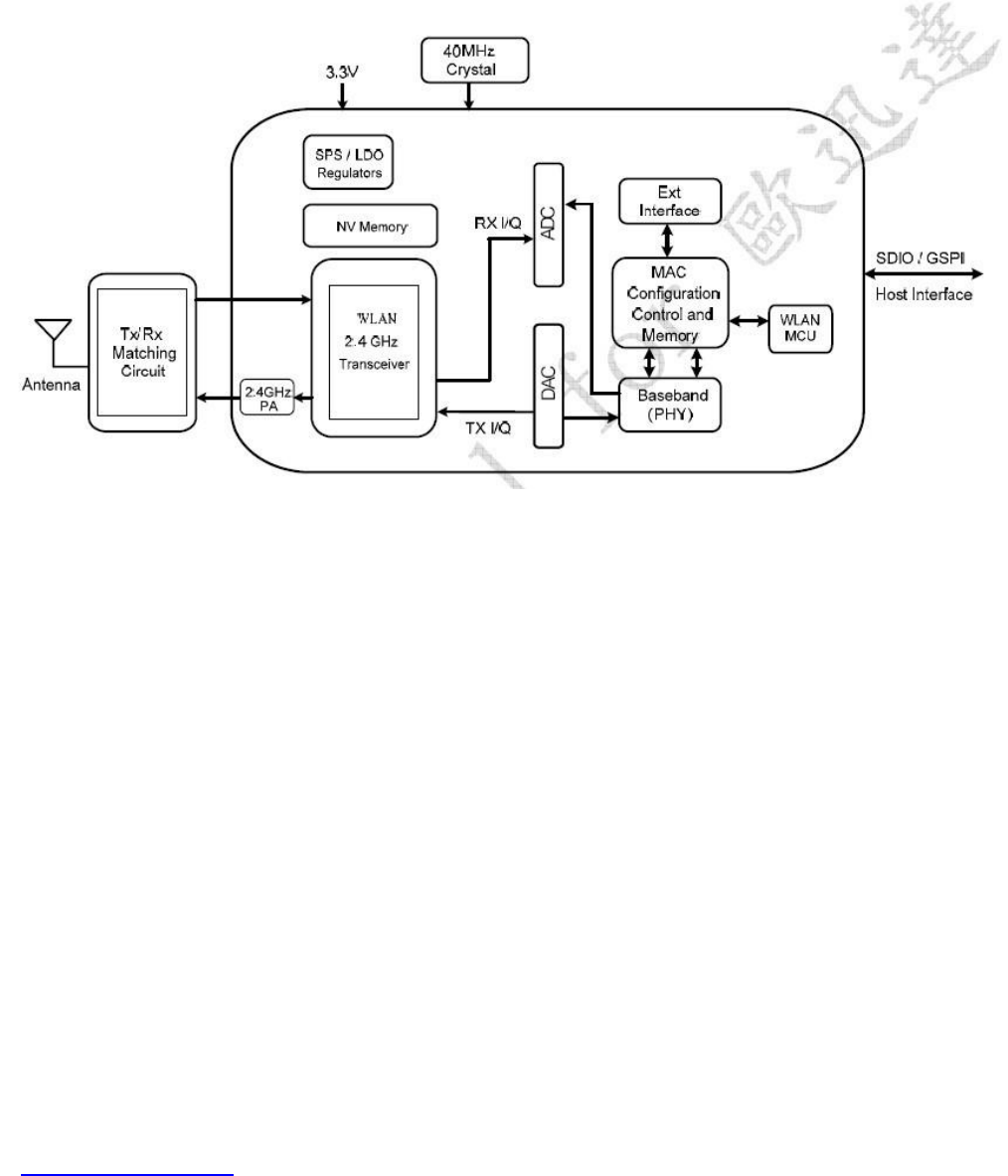
1.1 Overview
The general hardware for the module is shown in Figure 1. This WLAN Module design is based
on Realtek RTL8189ES. It is a highly integrated single-chip 1*1 MIMO (Multiple In Multiple Out)
Wireless LAN (WLAN) SDIO network interface controller complying with the 802.11n
specification. It combines a MAC, a 1T1R capable baseband, and RF in a single chip. It is
designed to provide excellent performance with low power Consumption and enhance the
advantages of robust system and cost-effective.
Figure 1: Single-brand 11n (1*1) solution
1.2 Specification Reference
This specification is based on additional references listed as below.
iEEE 802.11b
iEEE 802.11g
iEEE 802.11n

FN-LINK TECHNOLOGY LIMITED
http://www.fn-link.com Page 5/14 3/27/2014
1.3 System Characteristics
Main Chipset Realtek RTL8189ES
Operating Frequency 2.412~2.462GHz
WIFI Standard Ieee802.11b/g/n 1*1
Modulation 802.11b: CCK(11, 5.5Mbps), QPSK(2Mbps), BPSK(1Mbps)
802.11 g/n: OFDM
PHY Data rates 802.11b: 11,5.5,2,1 Mbps
802.11g: 54,48,36,24,18,12,9,6 Mbps
802.11n: up to 150Mbps
Receiver Sensitivity 130M:-70dBm@10% PER; 108M:-70dBm@10% PER; 54M:
-70dBm@10% PER; 11M:-87dBm@8% PER; 6M:-90dBm@10%
PER; 1M:-92dBm@8% PER
Host Interface SDIO/GSPI
Operation Range Up to 150meters in open space
RF Power <9.0dBm@11n,<9.8dBm@11b,<9.5dBm@11g
RF Antenna Integral Antenna (0dBi gain)
OS Support Android / Win CE /iOS /Linux/Windows 2000/XP/Vista/WIN7
Security WEP,TKIP,AES,WPA,WPA2
Power Consumption 3.3Vdc 110mA Max
Operating Temperature
-20~ +45°C Ambient Temperature
Storage Temperature -40~ +70°C Ambient Temperature
Humidity 5% to 90% maximum (non-condensing)
Dimension Typical L14.00*W12.50*T2.00mm
FN-LINK TECHNOLOGY LIMITED
http://www.fn-link.com Page 6/14 3/27/2014
2. Mechanical Specification
2.1 Outline Drawing
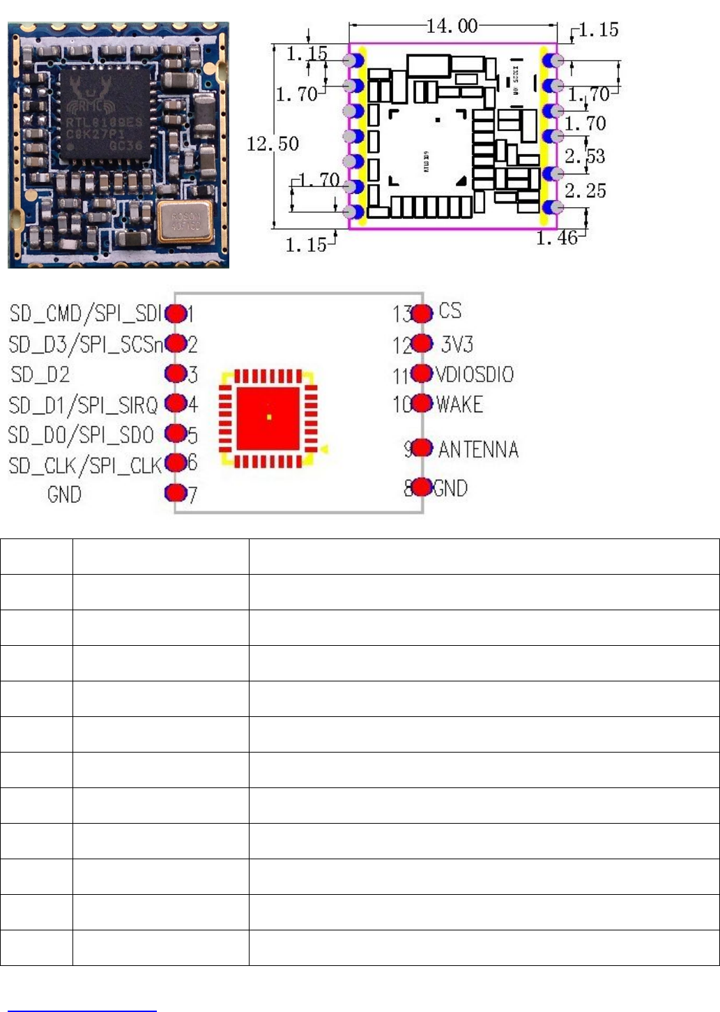
2.2 Connector Pin Definition
Pin # Name Description
1 SD_CMD SDIO Command Input
2 SD_D3 SDIO Data Line 3
3 SD_D2 SDIO Data Line 2
4 SD_D1 SDIO Data Line 1
5 SD_D0 SDIO Data Line 0
6 SD_CLK SDIO Clock Input
7 GND POWER GND
8 GND POWER GND
9 ANTENNA RF OUT
10 WAKE Wake Function
11 VDIOSDIO SDIO Voltage 1.8V-3.3V
FN-LINK TECHNOLOGY LIMITED
http://www.fn-link.com Page 7/14 3/27/2014
12 3.3 Power Supply
13 CS PDn
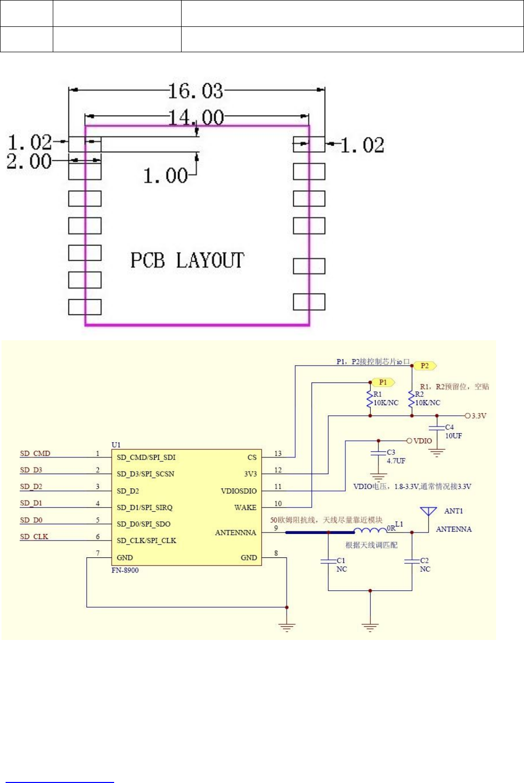
2.3 Layout reference

FN-LINK TECHNOLOGY LIMITED
http://www.fn-link.com Page 8/14 3/27/2014
3. RF Performance
3.1Transmitter Power (Unit in dBm) (Typical 1,6,11 Channel)
11n 20MHz Mode (Spec<9dBm)
Mode Rate Channel 1 Channel 6 Channel 11
MCS0 8.5 8.3 8.4
MCS3 8.3 8.4 8.3
MCS5 8.5 8.2 8.5
11n
20MHz
MCS7 8.3 8.5 8.4
11n 40MHz Mode ( Spec<9dBm)
Mode Rate Channel 1 Channel 6 Channel 11
MCS0 7.6 7.4 7.3
MCS3 7.5 7.2 7.4
MCS5 7.3 7.5 7.6
11n
40MHz
MCS7 7.5 7.2 7.3
3.2 EVM
11b Mode: unit in % (Spec≦10%)
Mode Rate Channel 1 Channel 6 Channel 11
1Mbps 5.2 5.3 5.5
2Mbps 5.4 5.3 5.5
5.5Mbps 5.6 5.3 5.5
11b
CCK
11Mbps 5.9 5.6 5.9
11g Mode: unit in dB (Spec≦-25dB)
Mode Rate Channel 1 Channel 6 Channel 11
6Mbps -29.3 -29.5 -29.1
18Mbps -29.2 -28.5 -29.3
36Mbps -28.5 -28.9 -28.1
11g
OFDM
54Mbps -29.8 -29.1 -29.0
11n 20MHz Mode: unit in dB(Spec≦-25dB)
Mode Rate Channel 1 Channel 6 Channel 11
MCS0 -28.3 -28.5 -28.5
MCS3 -28.2 -29.5 -28.4
MCS5 -28.3 -28.5 -28.1
11n
20MHz
MCS7 -28.1 -28.4 -28.0
11n 40MHz Mode: unit in dB (Spec≦-25dB)

FN-LINK TECHNOLOGY LIMITED
http://www.fn-link.com Page 9/14 3/27/2014
Mode Rate Channel 1 Channel 6 Channel 11
MCS0 -27.3 -27.5 -26.5
MCS3 -27.2 -26.5 -26.4
MCS5 -27.3 -26.5 -26.1
11n
40MHz
MCS7 -28.3 -28.2 -28.1
3.3 Transmit Center Frequency Tolerance
11g transmit center frequency tolerance test result:
Channel CH6
Result(ppm) 0.65
Frequency tolerance 1.57KHz
Pass/Fail PASS
11n transmit center frequency tolerance test result:
Channel CH6
Result(ppm) 0.71
Frequency tolerance 1.73KHz
Pass/Fail PASS
3.4 Receiver sensitivity (Unit in dBm)
11b Mode: 1RX (Spec≦-75dBm)
Mode Rate Channel 1 Channel 6 Channel 11
1Mbps -90 -90 -90
2Mbps -90 -90 -91
5.5Mbps -89 -89 -88
11b
11Mbps -85 -85 -86
11g Mode: 1RX (Spec≦-65dBm)
Mode Rate Channel 1 Channel 6 Channel 11
6Mbps -90 -90 -90
9Mbps -90 -90 -91
12Mbps -89 -89 -88
18Mbps -85 -85 -86
24Mbps -78 -79 -78
36Mbps -75 -75 -75
48Mbps -71 -71 -71
11g
54Mbps -69 -68 -70
11n 20MHz Mode: 1RX (Spec≦-65dBm)
Mode Rate Channel 1 Channel 6 Channel 11
MCS0 -85 -85 -85
MCS1 -82 -82 -82
11n
20MHz
MCS2 -80 -80 -80

FN-LINK TECHNOLOGY LIMITED
http://www.fn-link.com Page 10/14 3/27/2014
MCS3 -77 -77 -77
MCS4 -73 -74 -74
MCS5 -69 -70 -69
MCS6 -68 -68 -68
MCS7 -66 -66 -66
11n 40MHz Mode: 1RX (Spec≦-60dBm)
Mode Rate Channel 1 Channel 6 Channel 11
MCS0 -83 -83 -83
MCS1 -79 -80 -80
MCS2 -77 -77 -77
MCS3 -74 -75 -75
MCS4 -71 -71 -71
MCS5 -67 -67 -67
MCS6 -65 -65 -65
11n
40MHz
MCS7 -63 -63 -63
3.5 Power Consumption
Mode Status Power(mW) Note
3.3Vx70mA =231 20M Link
3.3Vx75 mA =248 40M
3.3Vx75mA =248 20M RX
3.3Vx75 mA =248 40M
3.3Vx100 mA =330 20M TX
3.3Vx110 mA=363 40M
Power save mode 3.3Vx20 mA =66 DTIM=100ms
Device Disable 3.3Vx25 mA =82.5
OS
Windows XP
Radio Off 3.3Vx0 mA =0
FN-LINK TECHNOLOGY LIMITED
http://www.fn-link.com Page 11/14 3/27/2014
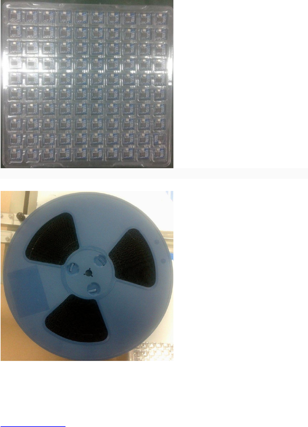
4.0 Package
4.1 blister packaging
Remark: 100pcs/Layer, 10Layer/Bag, 1,000pcs/Bag
4.2 the roll package
2,000pcs/roll
FN-LINK TECHNOLOGY LIMITED
http://www.fn-link.com Page 12/14 3/27/2014
5.0 User’s Manual
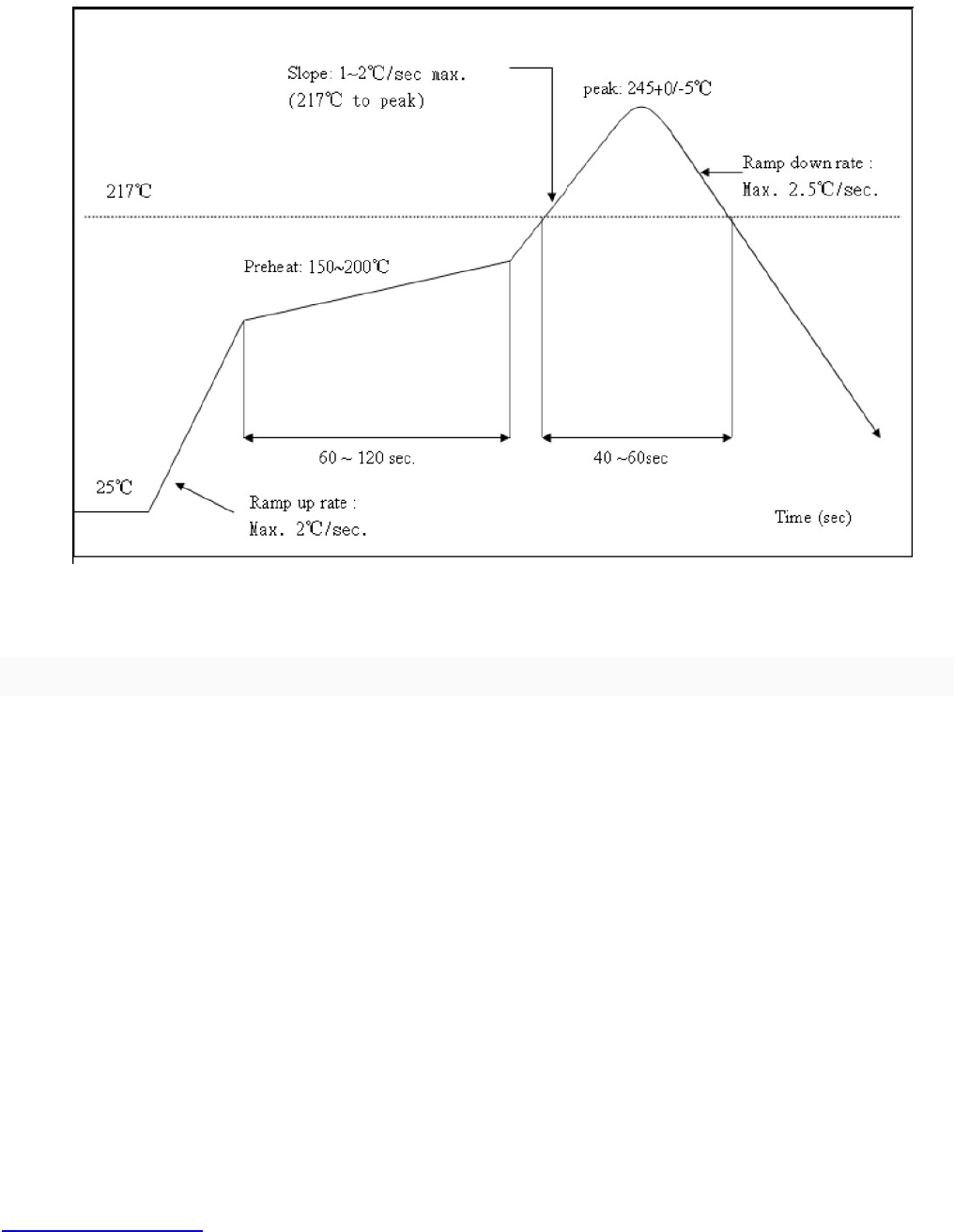
5.1 Recommended Reflow curve
Referred to IPC/JEDEC standard
Peak Temperature : <250°C
Number of Times : ≤2 times
5.2 Patch WIFI modules installed before the notice:
WIFI module installed note:
1. Please press 1 : 1 and then expand outward proportion to 0.7 mm, 0.12 mm thickness When open a
stencil
2. Take and use the WIFI module, please insure the electrostatic protective measures.
3. Reflow soldering temperature should be according to the customer the main size of the products, such
as the temperature set at 250 + 5 ℃ for the MID motherboard.
About the module packaging, storage and use of matters needing attention are as follows:
1. The module of the reel and storage life of vacuum packing: 1). Shelf life: 8 months, storage
environment conditions: temperature in: < 40 ℃, relative humidity: < 90% r.h.
2. The module vacuum packing once opened, time limit of the assembly:
Card: 1) check the humidity display value should be less than 30% (in blue), such as: 30% ~ 40% (pink),
or greater than 40% (red) the module have been moisture absorption.
2.) factory environmental temperature humidity control: ≦ 30% ℃, ≦ 60% r.h..
3). Once opened, the workshop the preservation of life for 168 hours.
3. Once opened, such as when not used up within 168 hours:
1). The module must be again to remove the module moisture absorption.
2). The baking temperature: 125 ℃, 8 hours.
3.) after baking, put the right amount of desiccant to seal packages.

FN-LINK TECHNOLOGY LIMITED
http://www.fn-link.com Page 13/14 3/27/2014
FCC ID: 2AATL-F89ESSM23
This device complies with Part 15 of the FCC Rules. Operation is subject to the following two conditions:
(1) this device may not cause harmful interference, and (2) this device must accept any interference
received, including interference that may cause undesired operation.
FCC Caution: Any changes or modifications not expressly approved by the party responsible for
compliance could void the user's authority to operate the equipment.
NOTE: This equipment has been tested and found to comply with the limits for a Class B digital device,
pursuant to Part 15 of the FCC Rules. These limits are designed to provide reasonable protection
against harmful interference in a residential installation. This equipment generates, uses and can radiate
radio frequency energy and, if not installed and used in accordance with the instructions, may cause
harmful interference to radio communications. However, there is no guarantee that interference will not
occur in a particular installation. If this equipment does cause harmful interference to radio or television
reception, which can be determined by turning the equipment off and on, the user is encouraged to try to
correct the interference by one or more of the following measures:
-- Reorient or relocate the receiving antenna.
-- Increase the separation between the equipment and receiver.
-- Connect the equipment into an outlet on a circuit different
from that to which the receiver is connected.
-- Consult the dealer or an experienced radio/TV technician for help.
IMPORTANT NOTE:
This device is intended only for OEM integrators under the following conditions:
(1) According to FCC Part 15 Subpart C Section 15.212, the radio elements of the modular transmitter
must have their own shielding. However, due to there is no shielding for this WIFI Module, this module is
granted as a Limited Modular Approval.
(2) This module has been designed to operate with a Integral antenna having a maximum gain of 0dBi.
Only this type of antenna may be used.
(3) Integration is typically strictly restricted to Grantee himself or dedicated OEM integrators under
control of the Grantee.
As long as 3 conditions above are met, further transmitter test will not be required.
However, the OEM integrator is still responsible for testing their end-product for any additional
compliance requirements required with this module installed (for example, digital device emissions, PC
peripheral requirements, etc.).
IMPORTANT NOTE:
In the event that these conditions can not be met (for example certain laptop configurations or
co-location with another transmitter).then the FCC authorization is no longer considered valid and the
FCC ID can not be used on the final product. In these circumstances, the OEM integrator will be
responsible for re-evaluating the end product (including the transmitter) and obtaining a separate FCC
authorization.
IMPORTANT NOTE:
This module is intended for OEM integrator only and the OEM integrators are instructed to ensure that
the end user has no manual instructions to remove or install the device. The OEM integrator is still
responsible for the FCC compliance requirement of the end product, which integrates this module.
LABEL OF THE END PRODUCT:
The final end product must be labeled in a visible area with the following “Contains TX FCC ID:
2AATL-F89ESSM23”. If the size of the end product is smaller than 8x10cm, then additional FCC part
15.19 statement is required to be available in the users manual: This device complies with Part 15 of the
FCC Rules. Operation is subject to the following two conditions: (1) this device may not cause harmful
interference, and (2) this device must accept any interference received, including interference that may
cause undesired operation.
We hereby requests for part 15 unlicensed limited modular transmitter approval of our device, described
as follows:
This RF Module does not have an own shielding, so that a Limited Modular Approval (LMA) was granted:
This RF module is strictly limited to the integration by the Grantee himself or the dedicated OEM

FN-LINK TECHNOLOGY LIMITED
http://www.fn-link.com Page 14/14 3/27/2014
integrators under the control of the Grantee.
Proper measurements of the host device including this RF module (radiated spurious emissions and
bandedge) are required to assure compliance with the FCC regulations.