HUNAN FN LINK TECHNOLOGY FNCC2541 Bluetooth 4.0 Module User Manual
FN-LINK TECHNOLOGY LIMITED Bluetooth 4.0 Module Users Manual
User manual

FN-LINK TECHNOLOGY LIMITED
http://www.fn-link.com Page 1/8
Bluetooth Low Energy (BLE) Module
FN-CC2541
User Manual / User Guide
FN-LINK TECHNOLOGY LIMITED
http://www.fn-link.com Page 2/8
1. Introduction
FN-CC2541 is 2.4GHz Bluetooth low power system on chip (SoC), support 250kbps, 500kbps, 1Mbps and
2Mbps data rate, with connecting budget excellent, but the front end the application, receiving 1Mbps with a
sensitivity of -94dBm, mainly used in the 2.4GHz Bluetooth low energy system, personal 2.4GHz system,
man-machine interface such as a keyboard, mouse, and remote control etc., sports and leisure equipment,
mobile phone accessories and consumer electronics.
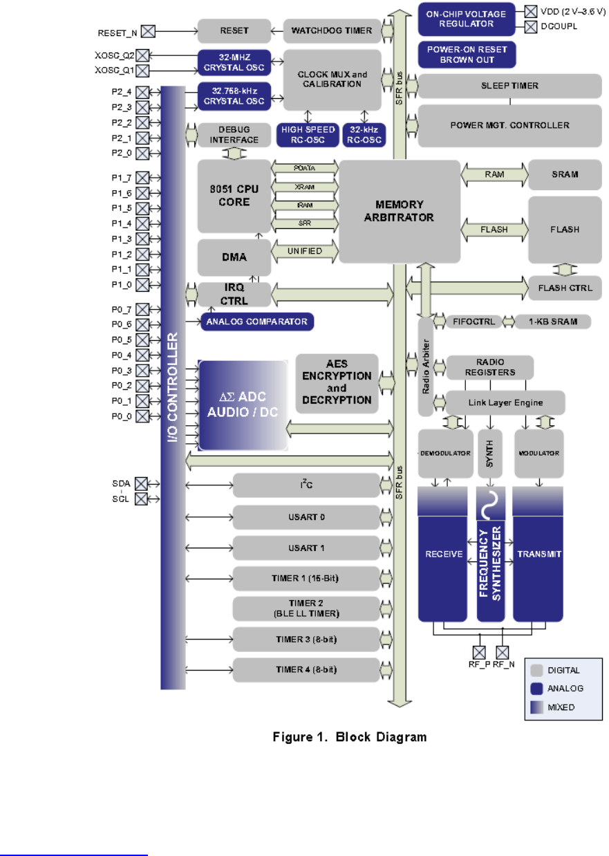
1.1 Overview
The block diagram for the module is shown in Figure 1. The modules can be roughly divided into one of
three categories: CPU-related modules; modules related to power, test, and clock distribution; and
radio-related modules.
FN-LINK TECHNOLOGY LIMITED
http://www.fn-link.com Page 3/8
1.2 SOFTWARE FEATURES
Sample Applications and Profiles
Generic Applications for GAP Central and Peripheral Roles
Proximity, Accelerometer, Simple keys, and Battery GATT Services
More Applications Supported in BLE Software Stack
Multiple Configuration Options
Single-chip configuration, allowing applications to run on CC2541
Network processor interface for applications running on an external microcontroller
BTool-Windows PC application for evaluation, development, and test
1.3 APPLICATIONS
2.4GHz Bluetooth low energy systems
Proprietary 2.4GHz systems
Human-interface devices (Keyboard, Mouse, Remote Control)
Sports and leisure equipment
Mobile Phone accessories
Consumer elecctronics
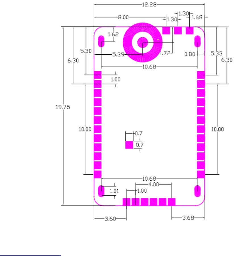
2. Mechanical Specification
2.1 Outline Drawing
FN-LINK TECHNOLOGY LIMITED
http://www.fn-link.com Page 4/8
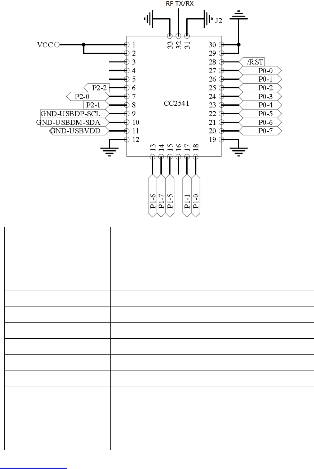
2.2 Connector Pin Definition
Pin #
Name
Description
1
VCC
2-3.6V
2
VCC
2-3.6V
3
NC
NOP
4
NC
NOP
5
NC
NOP
6
P2-2
7
P2-0
8
P2-1
9
GND
USBDP-SCL
10
GND
USBDM-SDA
11
GND
USBVDD
12
GND
GND
13
P1-6

FN-LINK TECHNOLOGY LIMITED
http://www.fn-link.com Page 5/8
14
P1-7
15
P1-5
16
NC
NOP
17
P1-1
18
P1-0
19
GND
GND
20
P0-7
21
P0-6
22
P0-5
23
P0-4
24
P0-3
25
P0-2
26
P0-1
27
P0-0
28
RST
RESET
29
GND
GND
30
GND
GND
31
GND
J2
32
TX/RX
RF TX/RX
33
GND
GND
FN-LINK TECHNOLOGY LIMITED
http://www.fn-link.com Page 6/8
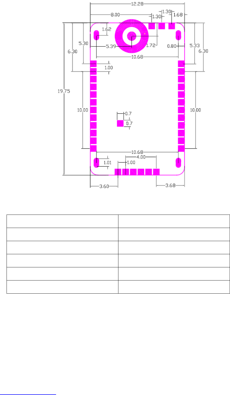
2.3 Layout reference
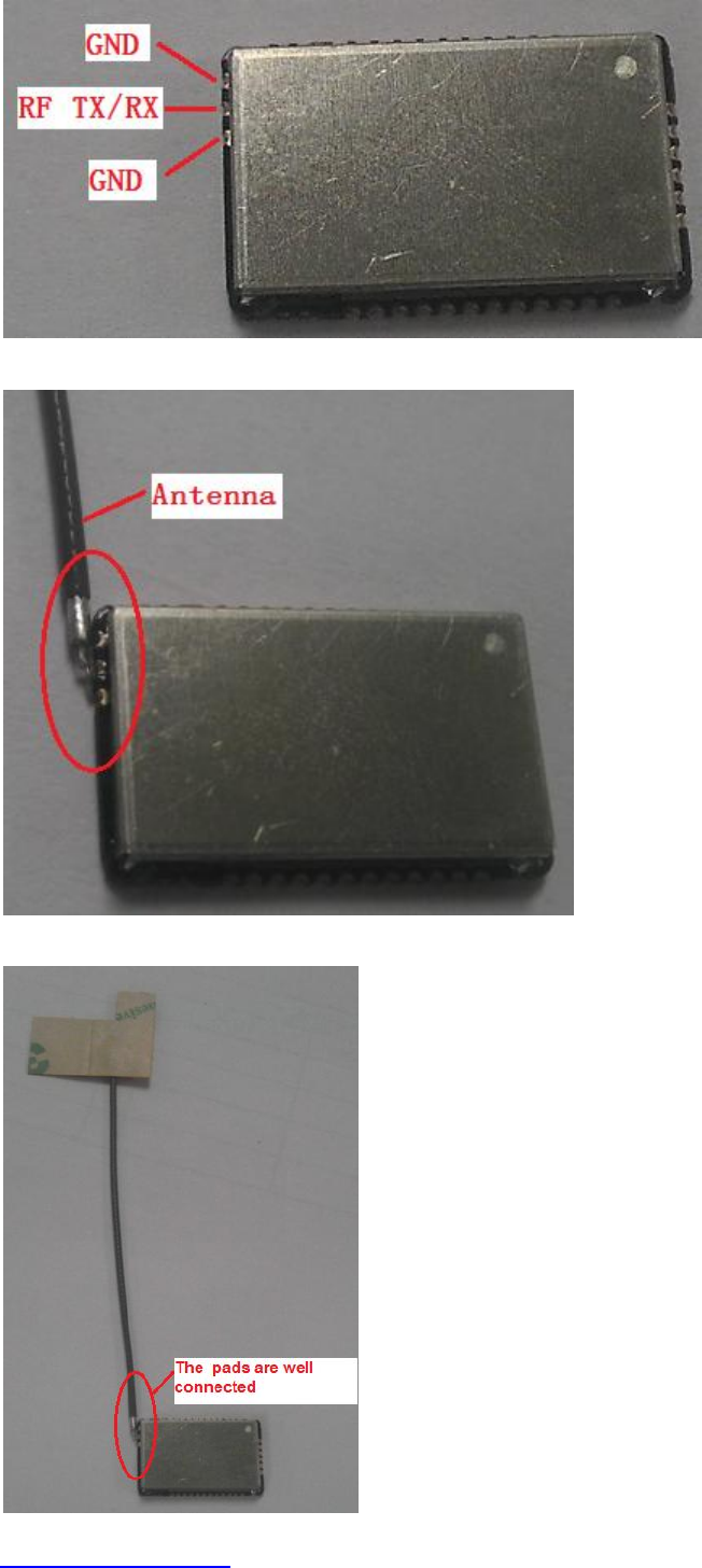
3. Antenna Specification
Antenna plate
FPC antenna
Antenna gain
0dBi
Frequency range
2.4GHZ-2.483GHZ
POWER
0dBm
Connector type
Fixed antenna
company name
HJ HECH
FN-LINK TECHNOLOGY LIMITED
http://www.fn-link.com Page 7/8
4. Antenna Installation Guide
4.1 Check FN-CC2541 Module connection pin is clean for soldering.
4.2 Place the Module on the Master PCB. Then solder it.
4.3 After soldering, Check all pads are well connected.
FN-LINK TECHNOLOGY LIMITED
http://www.fn-link.com Page 8/8
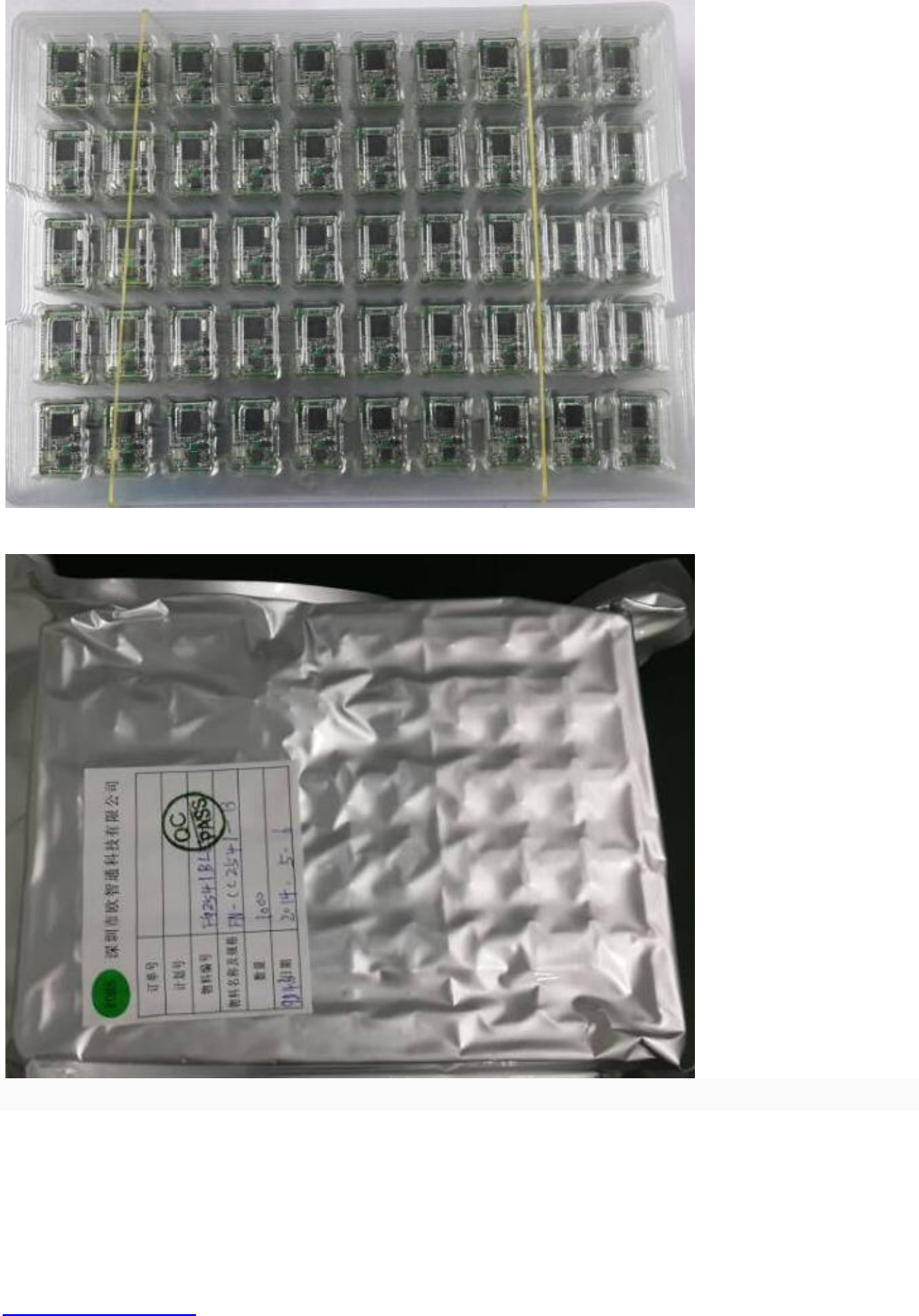
5. Package
5.1 blister packaging
Vacuum packaging
A piece of 50 PCS (500 pcs/bag)
FCC Statement:
The final end product must be labeled in a visible area with the following "Contains TX FCC
ID:2AATL-FNCC2541". If the size of the end product is smaller than 8x10cm, then additional
FCC part 15.19 stayement is required to be availale in the users manual:
This device complies with part 15 of the FCC Rules. Operation is subject to the following
two conditions: (1) This device may not cause harmful interference, and (2) this device
must accept any interference received, including interference that may cause undesired
operation.
This equipment has been tested and found to comply with the limits for a Class B digital
device, pursuant to part 15 of the FCC Rules. These limits are designed to provide
reasonable protection against harmful interference in a residential installation. This
equipment generates, uses and can radiate radio frequency energy and, if not installed
and used in accordance with the instructions, may cause harmful interference to radio
communications. However, there is no guarantee that interference will not occur in a
particular installation. If this equipment does cause harmful interference to radio or
television reception, which can be determined by turning the equipment off and on, the
user is encouraged to try to correct the interference by one or more of the following
measures:
—Reorient or relocate the receiving antenna.
—Increase the separation between the equipment and receiver.
—Connect the equipment into an outlet on a circuit different from that to which the
receiver is connected.
—Consult the dealer or an experienced radio/TV technician for help.
Caution: Any changes or modifications not expressly approved by the party responsible
for compliance could void the user's authority to operate the equipment.
FCC Radiation Exposure Statement:
This modular complies with FCC RF radiation exposure limits set forth for an uncontrolled environment.
This transmitter must not be co-located or operating in conjunction with any other antenna or transmitter.
The OEM integrator is still responsible for testing their end-product for any additional compliance
requirements required with this module installed.
This device is intended only for OEM integrators under the following conditions:
1)This module is granted as a Single Modular Approval.
2)This device has been designed to operate with a FPC antenna having a maximum gain of 0dBi.Only
this type of antenna may be used.