HUSQVARNA Lawn, Tractor Manual L0402136
User Manual: HUSQVARNA HUSQVARNA Lawn, Tractor Manual HUSQVARNA Lawn, Tractor Owner's Manual, HUSQVARNA Lawn, Tractor installation guides
Open the PDF directly: View PDF ![]() .
.
Page Count: 52

Husqvarna
02139
G ! H2548
Owner's Manual
For Parts and Service, call 1-800-448-7543
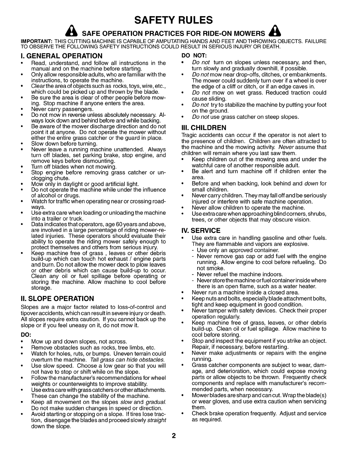
SAFETY RULES
_, SAFE OPERATION PRACTICES FOR RIDE-ON MOWERS
IMPORTANT: THIS CUTTING MACHINE IS CAPABLE OF AMPUTATINGHANDS AND FEETANDTHROWING OBJECTS. FAILURE
TO OBSERVE THE FOLLOWING SAFETY INSTRUCTIONS COULD RESULT IN SERIOUS INJURY OR DEATH.
I. GENERAL OPERATION
• Read, understand, and follow all instructions in the
manual and on the machine before starting.
• Only allow responsible adults, who are familiar with the
instructions, to operate the machine.
• Clear the area of objects such as rocks, toys, wire, etc.,
which could be picked up and thrown by the blade.
• Be sure the area is clear of other people before mow-
ing. Stop machine if anyone enters the area.
• Never carry passengers.
• Do not mow in reverse unless absolutely necessary. Al-
ways look down and behind before and while backing.
• Be aware of the mower discharge direction and do not
point it at anyone. Do not operate the mower without
either the entire grass catcher or the guard in place.
• Slow down before turning.
• Never leave a running machine unattended. Always
turn off blades, set parking brake, stop engine, and
remove keys before dismounting.
• Turn off blades when not mowing.
• Stop engine before removing grass catcher or un-
clogging chute.
• Mow only in daylight or good artificial light.
• Do not operate the machine while under the influence
of alcohol or drugs.
• Watch for traffic when operating near or crossing road-
ways.
• Use extra care when loading or unloading the machine
into a trailer or truck.
• Data indicates that operators, age 60 years and above,
are involved in a large percentage of riding mower-re-
lated injuries. These operators should evaluate their
ability to operate the riding mower safely enough to
protect themselves and others from serious injury.
• Keep machine free of grass, leaves or other debris
build-up which can touch hot exhaust /engine parts
and burn. Do not allow the mower deck to plow leaves
or other debris which can cause build-up to occur.
Clean any oil or fuel spillage before operating or
storing the machine. Allow machine to cool before
storage.
I1. SLOPE OPERATION
Slopes are a major factor related to loss-of-control and
tipover accidents, which can result in severe injury or death.
All slopes require extra caution. If you cannot back up the
slope or if you feel uneasy on it, do not mow it.
DO:
• Mow up and down slopes, not across.
• Remove obstacles such as rocks, tree limbs, etc.
• Watch for holes, ruts, or bumps. Uneven terrain could
overturn the machine. Tall grass can hide obstacles.
• Use slow speed. Choose a low gear so that you will
not have to stop or shift while on the slope.
• Follow the manufacturer's recommendations for wheel
weights or counterweights to improve stability.
• Use extra care with grass catchers or other attachments.
These can change the stability of the machine.
• Keep all movement on the slopes slow and gradual
Do not make sudden changes in speed or direction.
• Avoid starting or stopping on a slope. If tires lose trac-
tion, disengage the blades and proceed slowly straight
down the slope.
DO NOT:
•Do not turn on slopes unless necessary, and then,
turn slowly and gradually downhill, if possible.
•Do not mow near drop-offs, ditches, or embankments.
The mower could suddenly turn over if a wheel is over
the edge of a cliff or ditch, or if an edge caves in.
•Do not mow on wet grass. Reduced traction could
cause sliding.
•Do not try to stabilize the machine by putting your foot
on the ground.
•Do not use grass catcher on steep slopes.
III. CHILDREN
Tragic accidents can occur if the operator is not alert to
the presence of children. Children are often attracted to
the machine and the mowing activity. Never assume that
children will remain where you last saw them.
•Keep children out of the mowing area and under the
watchful care of another responsible adult.
•Be alert and turn machine off if children enter the
area.
•Before and when backing, look behind and down for
small children.
•Nevercarrychildren. Theymayfalloffandbeseriously
injured or interfere with safe machine operation.
•Never allow children to operate the machine.
•Use extracare when approaching blind corners, shrubs,
trees, or other objects that may obscure vision.
IV. SERVICE
•Use extra care in handling gasoline and other fuels.
They are flammable and vapors are explosive.
Use only an approved container.
Never remove gas cap or add fuel with the engine
running. Allow engine to cool before refueling. Do
not smoke.
Never refuel the machine indoors.
Never store the machine orfuel containerinsidewhere
there is an open flame, such as a water heater.
•Never run a machine inside a closed area.
•Keep nuts and bolts, especially blade attachment bolts,
tight and keep equipment in good condition.
•Never tamper with safety devices. Check their proper
operation regularly.
•Keep machine free of grass, leaves, or other debris
build-up. Clean oil or fuel spillage. Allow machine to
cool before storing.
• Stop and inspect the equipment ifyou strike an object.
Repair, if necessary, before restarting.
•Never make adjustments or repairs with the engine
running.
• Grass catcher components are subject to wear, dam-
age, and deterioration, which could expose moving
parts or allow objects to be thrown. Frequently check
components and replace with manufacturer's recom-
mended parts, when necessary.
•Mower blades are sharp and can cut.Wrap the blade(s)
or wear gloves, and use extra caution when servicing
them.
• Check brake operation frequently. Adjust and service
as required.
2
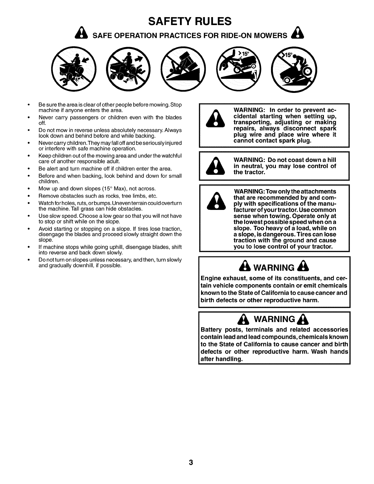
SAFETY RULES
A SAFE OPERATION PRACTICES FOR RIDE-ON MOWERS A
• Be sure the area is clear of other people before mowing. Stop
machine if anyone enters the area.
• Never carry passengers or children even with the blades
off.
• Do not mow in reverse unless absolutely necessary. Always
look down and behind before and while backing.
• Never carry children.They may fall off and be seriously injured
or interfere with safe machine operation.
• Keep children out of the mowing area and under the watchful
care of another responsible adult.
• Be alert and turn machine off if children enter the area.
• Before and when backing, look behind and down for small
children.
• Mow up and down slopes (15 ° Max), not across.
• Remove obstacles such as rocks, tree limbs, etc.
• Watch for holes, ruts, or bumps. Uneven terrain could overturn
the machine. Tall grass can hide obstacles.
• Use slow speed. Choose a low gear so that you will not have
to stop or shift while on the slope.
• Avoid starting or stopping on a slope. If tires lose traction,
disengage the blades and proceed slowly straight down the
slope.
• If machine stops while going uphill, disengage blades, shift
into reverse and back down slowly.
• Do not turn on slopes unless necessary, and then, turn slowly
and gradually downhill, if possible.
AWARNING: In order to prevent ac-
cidental starting when setting up,
transporting, adjusting or making
repairs, always disconnect spark
plug wire and place wire where it
cannot contact spark plug.
A WARNING: Do not coast down a hill
in neutral, you may lose control of
the tractor.
AWARNING: Tow only the attachments
that are recommended by and com-
ply with specifications of the manu-
facturer of your tractor. Use common
sense when towing. Operate only at
the lowest possible speed when on a
slope. Too heavy of a load, while on
a slope, is dangerous. Tires can lose
traction with the ground and cause
you to lose control of your tractor.
A WARNING A
Engine exhaust, some of its constituents, and cer-
tain vehicle components contain or emit chemicals
known to the State of California to cause cancer and
birth defects or other reproductive harm.
A WARNING A
Battery posts, terminals and related accessories
contain lead and lead compounds, chemicals known
to the State of California to cause cancer and birth
defects or other reproductive harm. Wash hands
after handling.
3
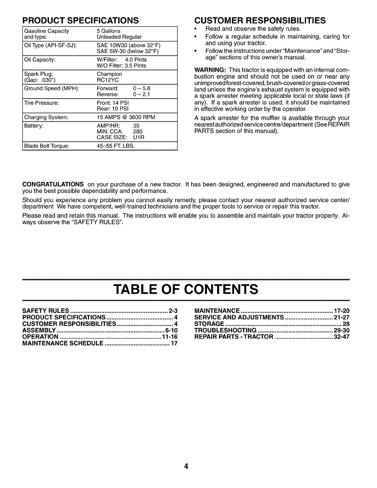
PRODUCT SPECIFICATIONS
Gasoline Capacity 5 Gallons
and type: Unleaded Regular
Oil Type(API-SF-SJ): SAE 10W30 (above 32°F)
SAE 5W-30 (below 32°F)
Oil Capacity: W/Filter: 4.0 Pints
W/O Filter: 3.5 Pints
Spark Plug: Champion
(Gap: .030") RC12YC
Ground Speed (MPH): Forward: 0 - 5.8
Reverse: 0 - 2.1
Tire Pressure: Front: 14 PSI
Rear: 10 PSI
Charging System: 15 AMPS @ 3600 RPM
Battery: AMP/HR: 35
MIN. CCA: 280
CASE SIZE: UIR
Blade Bolt Torque: 45-55 FT.LBS.
CUSTOMER RESPONSIBILITIES
• Read and observe the safety rules.
•Follow a regular schedule in maintaining, caring for
and using your tractor.
•Follow the instructions under"Maintenance" and "Stor-
age" sections of this owner's manual.
WARNING: This tractor is equipped with an internal com-
bustion engine and should not be used on or near any
unimproved forest-covered, brush-covered or grass-covered
land unless the engine's exhaust system is equipped with
a spark arrester meeting applicable local or state laws (if
any). If a spark arrester is used, it should be maintained
in effective working order by the operator.
A spark arrester for the muffler is available through your
nearest authorized servicecentre/department (See REPAIR
PARTS section of this manual).
CONGRATULATIONS on your purchase of a new tractor. It has been designed, engineered and manufactured to give
you the best possible dependability and performance.
Should you experience any problem you cannot easily remedy, please contact your nearest authorized service center/
department We have competent, well-trained technicians and the proper tools to service or repair this tractor.
Please read and retain this manual. The instructions will enable you to assemble and maintain your tractor properly. Al-
ways observe the "SAFETY RULES".
TABLE OF CONTENTS
SAFETY RULES ......................................................... 2-3
PRODUCT SPECIFICATIONS ....................................... 4
CUSTOMER RESPONSIBILITIES ................................. 4
ASSEMBLY ............................................................... 6-10
OPERATION ........................................................... 11-16
MAINTENANCE SCHEDULE ...................................... 17
MAINTENANCE ...................................................... 17-20
SERVICE AND ADJUSTMENTS ............................ 21-27
STORAGE .................................................................... 28
TROUBLESHOOTING ............................................ 29-30
REPAIR PARTS - TRACTOR .................................. 32-47
4

UNASSEMBLED PARTS
Gauge Wheel
Steering Wheel
Steering Sleeve
Steering
Wheel Adapter Steering
Wheel Insert
Steering Sleeve
Extension
Seat
(4) Lockwasher
(4) Hex Bolts 5/16-18 x 3/4
Mower
(2) Retainer Springs _,_
(double loop)
q_ (2)Flanged
(_)Pins
(4) Adjusting Bar
0.2 (4) Wheels
a
(4) Retainer.S, prings
(4) Clevis Pins
,.(4) Washers
/e x 3/4 x 14 Ga.
(4) Locknut
3/8-16 (4) Shoulder Bolt
Nose Roller
[Nose Roller
1
_r°aSce _''er
(2) Hex Bolts 5/16-18 x 1
(2) 5/1L°cknuts6-18@ _Retainer Spring
For Future Use
Keys
(2) Keys
Slope Sheet
5
ASSEMBLY
Your new tractor has been assembled at the factory with exception of those parts left unassembled for shipping purposes.
To ensure safe and proper operation of your tractor all parts and hardware you assemble must be tightened securely. Use
the correct tools as necessary to insure proper tightness.
TOOLS REQUIRED FOR ASSEMBLY
A socket wrench set will make assembly easier. Standard
wrench sizes are listed.
(1) Pliers (1) Tire pressure gauge
(2) 9/16" wrench (1) Utility knife
(1) 1/2" wrench (1) 3/4" socket w/drive ratchet
When right or left hand is mentioned in thismanual, it means
when you are in the operating position (seated behind the
steering wheel).
TO REMOVE TRACTOR FROM
CARTON
UNPACK CARTON
• Remove all accessible loose parts and parts cartons
from carton.
• Cut along dotted lines on all four panels of carton.
Remove end panels and lay side panels flat.
•Remove mower and packing materials.
• Check for any additional loose parts or cartons and
remove.
BEFORE REMOVING TRACTOR FROM
SKID
.,("_.___........_ STEERING WHEEL
_._ _ "_ INSERT
LOCK NUT
(_....._ LARGE FLAT WASHER
i
STEERING
\\_ "_ _:_ y/ STEERING
_-----_ _fWHEEL ADAP-
_-_'_ TOR
STEERING
WHEEL EXTENTION
STEERING
SHAFT
STEERING
SLEEVE
FIG. 1
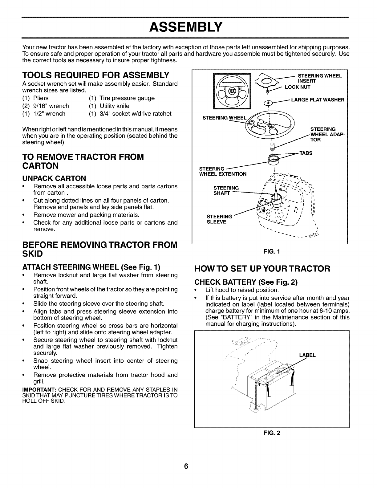
ATTACH STEERING WHEEL (See Fig. 1)
•Remove Iocknut and large flat washer from steering
shaft.
•Position front wheels of the tractor so they are pointing
straight forward.
• Slide the steering sleeve over the steering shaft.
• Align tabs and press steering sleeve extension into
bottom of steering wheel.
•Position steering wheel so cross bars are horizontal
(left to right) and slide onto steering wheel adapter.
• Secure steering wheel to steering shaft with Iocknut
and large flat washer previously removed. Tighten
securely.
• Snap steering wheel insert into center of steering
wheel.
•Remove protective materials from tractor hood and
grill.
IMPORTANT: CHECK FOR AND REMOVE ANY STAPLES IN
SKIDTHAT MAYPUNCTURETIRES WHERE TRACTOR ISTO
ROLL OFF SKID.
HOW TO SET UP YOUR TRACTOR
CHECK BATTERY (See Fig. 2)
•Lift hood to raised position.
•If this battery is put into service after month and year
indicated on label (label located between terminals)
charge battery for minimum of one hour at 6-10 amps.
(See "BATTERY" in the Maintenance section of this
manual for charging instructions).
LABEL
FIG. 2
6
ASSEMBLY
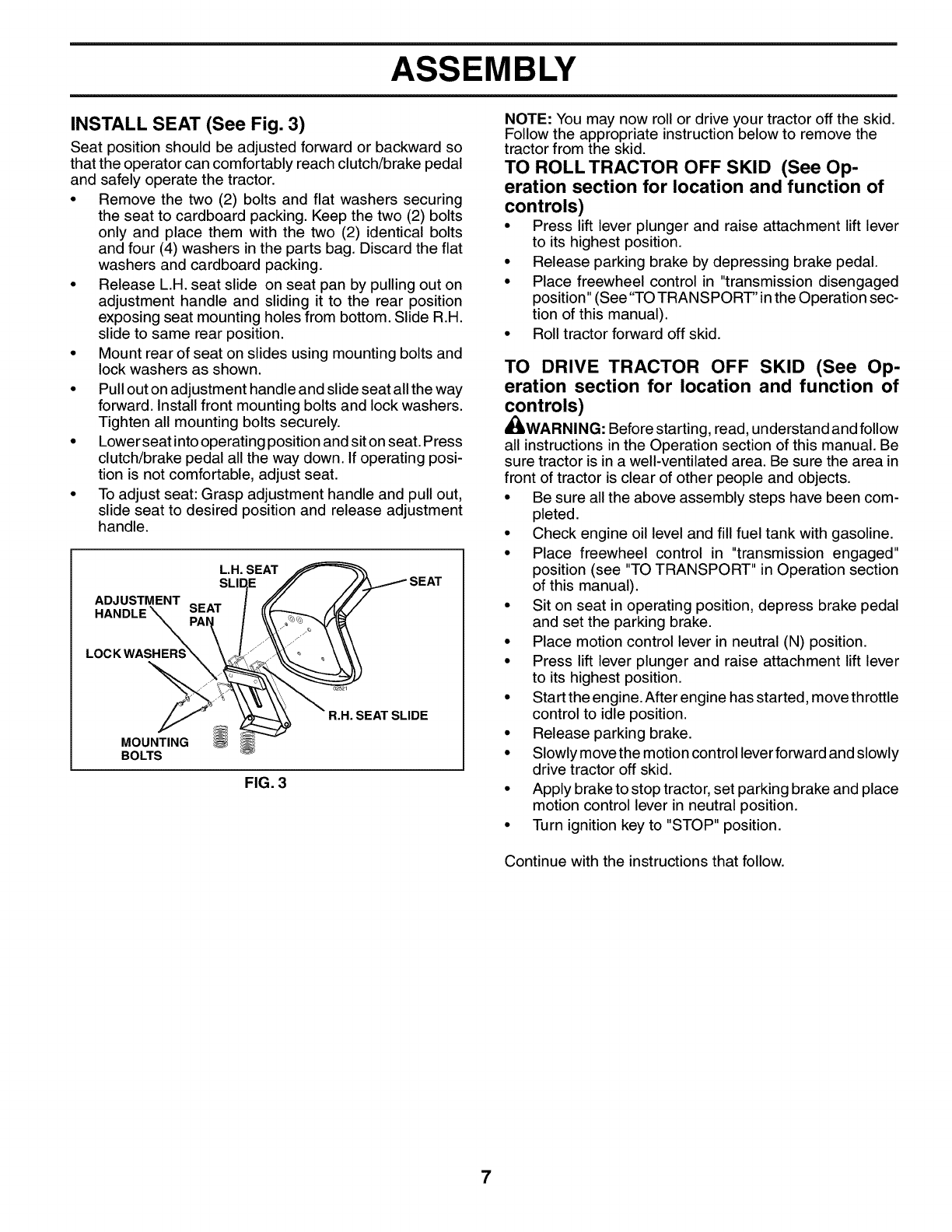
INSTALL SEAT (See Fig. 3)
Seat position should be adjusted forward or backward so
that the operator can comfortably reach clutch/brake pedal
and safely operate the tractor.
• Remove the two (2) bolts and flat washers securing
the seat to cardboard packing. Keep the two (2) bolts
only and place them with the two (2) identical bolts
and four (4) washers in the parts bag. Discard the flat
washers and cardboard packing.
•Release L.H. seat slide on seat pan by pulling out on
adjustment handle and sliding it to the rear position
exposing seat mounting holes from bottom. Slide R.H.
slide to same rear position.
•Mount rear of seat on slides using mounting bolts and
lock washers as shown.
•Pull outon adjustment handle and slide seat all the way
forward. Install front mounting bolts and lock washers.
Tighten all mounting bolts securely.
•Lower seat into operating positionand sit on seat. Press
clutch/brake pedal all the way down. If operating posi-
tion is not comfortable, adjust seat.
•To adjust seat: Grasp adjustment handle and pull out,
slide seat to desired position and release adjustment
handle.
ADJUSTMENT
HANDLE
L.H. SEAT SEAT
MOUNTING
BOLTS
FIG. 3
R.H. SEAT SLIDE
NOTE: You may now roll or drive your tractor off the skid.
Follow the appropriate instruction below to remove the
tractor from the skid.
TO ROLL TRACTOR OFF SKID (See Op-
eration section for location and function of
controls)
• Press lift lever plunger and raise attachment lift lever
to its highest position.
• Release parking brake by depressing brake pedal.
• Place freewheel control in "transmission disengaged
position" (See"TO TRANSPORT" in the Operation sec-
tion of this manual).
• Roll tractor forward off skid.
TO DRIVE TRACTOR OFF SKID (See Op-
eration section for location and function of
controls)
_WARNING: Before starting, read, understand and follow
all instructions in the Operation section of this manual. Be
sure tractor is in a well-ventilated area. Be sure the area in
front of tractor is clear of other people and objects.
• Be sure all the above assembly steps have been com-
pleted.
• Check engine oil level and fill fuel tank with gasoline.
• Place freewheel control in "transmission engaged"
position (see "TO TRANSPORT" in Operation section
of this manual).
• Sit on seat in operating position, depress brake pedal
and set the parking brake.
• Place motion control lever in neutral (N) position.
• Press lift lever plunger and raise attachment lift lever
to its highest position.
• Start the engine. After engine has started, move throttle
control to idle position.
• Release parking brake.
• Slowly move the motion control lever forward and slowly
drive tractor off skid.
• Apply brake to stop tractor, set parking brake and place
motion control lever in neutral position.
• Turn ignition key to "STOP" position.
Continue with the instructions that follow.
7
ASSEMBLY
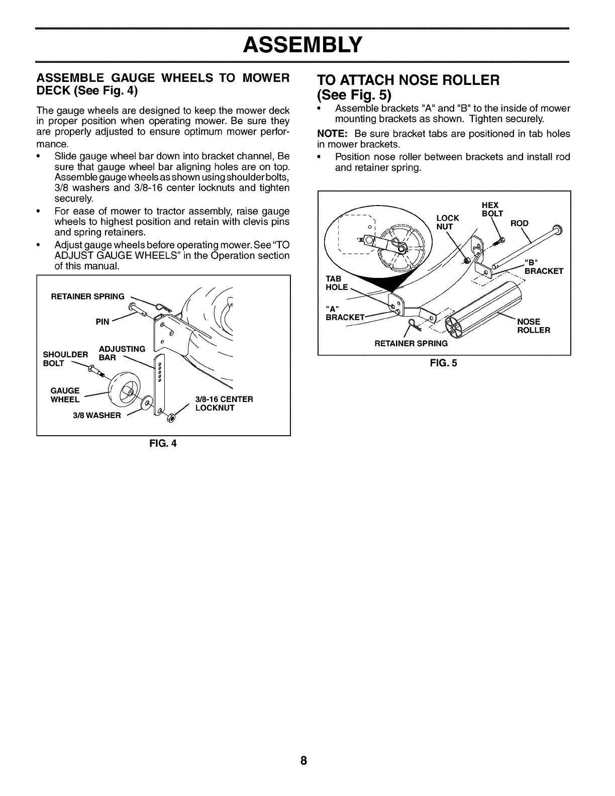
ASSEMBLE GAUGE WHEELS TO MOWER
DECK (See Fig, 4)
The gauge wheels are designed to keep the mower deck
in proper position when operating mower. Be sure they
are properly adjusted to ensure optimum mower perfor-
mance.
•Slide gauge wheel bar down into bracket channel, Be
sure that gauge wheel bar aligning holes are on top.
Assemble gauge wheels as shown using shoulder bolts,
3/8 washers and 3/8-16 center Iocknuts and tighten
securely.
• For ease of mower to tractor assembly, raise gauge
wheels to highest position and retain with clevis pins
and spring retainers.
• Adjust gauge wheels before operating mower. See"TO
ADJUST GAUGE WHEELS" in the Operation section
of this manual.
RETAINER SPRING
PIN
ADJUSTING
SHOULDER BAR
BOLT
GAUGE
WHEEL
3/8WASHER
_8-160ENTER
LOCKNUT
TO ATTACH NOSE ROLLER
(See Fig. 5)
• Assemble brackets "A" and "B" to the inside of mower
mounting brackets as shown. Tighten securely.
NOTE: Be sure bracket tabs are positioned in tab holes
in mower brackets.
• Position nose roller between brackets and install rod
and retainer spring.
HEX
BOLT
LOCK
NUT ROD
HOLE
"A"
NOSE
ROLLER
RETAINER SPRING
FIG. 5
FIG. 4
8
ASSEMBLY
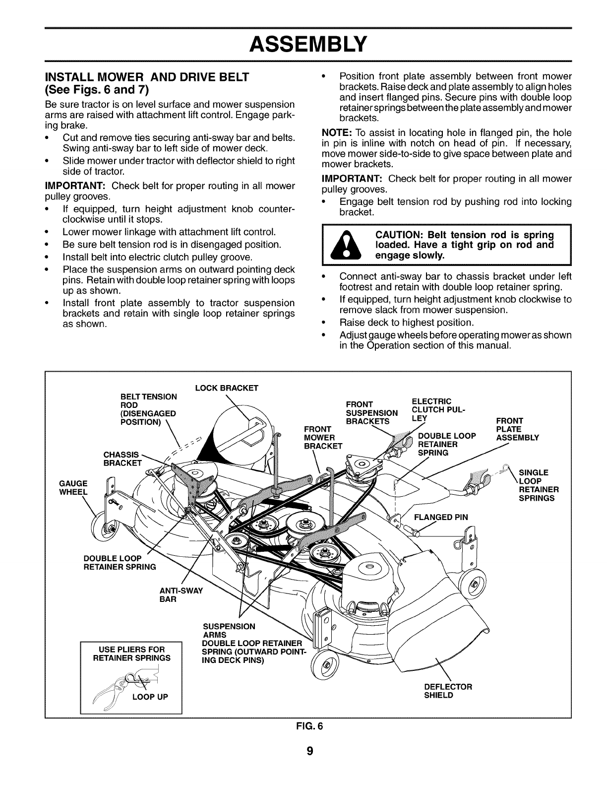
INSTALL MOWER AND DRIVE BELT
(See Figs. 6 and 7)
Be sure tractor is on level surface and mower suspension
arms are raised with attachment liftcontrol. Engage park-
ing brake.
• Cut and remove ties securing anti-sway bar and belts.
Swing anti-sway bar to left side of mower deck.
•Slide mower under tractor with deflector shield to right
side of tractor.
IMPORTANT: Check belt for proper routing in all mower
pulley grooves.
• If equipped, turn height adjustment knob counter-
clockwise until it stops.
• Lower mower linkage with attachment lift control.
• Be sure belt tension rod is in disengaged position.
• Install belt into electric clutch pulley groove.
• Place the suspension arms on outward pointing deck
pins. Retain with double loop retainer spring with loops
up as shown.
• Install front plate assembly to tractor suspension
brackets and retain with single loop retainer springs
as shown.
Position front plate assembly between front mower
brackets. Raise deck and plate assembly to align holes
and insert flanged pins. Secure pins with double loop
retainer springs between the plate assembly and mower
brackets.
NOTE: To assist in locating hole in flanged pin, the hole
in pin is inline with notch on head of pin. If necessary,
move mower side-to-side to give space between plate and
mower brackets.
IMPORTANT: Check belt for proper routing in all mower
pulley grooves.
• Engage belt tension rod by pushing rod into locking
bracket.
CAUTION: Belt tension rod is spring
loaded. Have a tight grip on rod and
engage slowly.
• Connect anti-sway bar to chassis bracket under left
footrest and retain with double loop retainer spring.
• If equipped, turn height adjustment knob clockwise to
remove slack from mower suspension.
• Raise deck to highest position.
• Adjust gauge wheels before operating mower as shown
in the Operation section of this manual.
GAUGE
WHEEL
LOCK BRACKET
BELT TENSION
ROD
(DISENGAGED
POSITION) _ _-
CHASSIS _"
BRACKET
FRONT ELECTRIC
SUSPENSION CLUTCH PUL-
BRACKETS LEY
FRONT
MOWER DOUBLE LOOP
BRACKET RETAINER
SPRING
FLANGED PIN
FRONT
PLATE
ASSEMBLY
SINGLE
RETAINER
SPRINGS
DOUBLE LOOP
RETAINER SPRING
ANTI-SWAY
BAR
USE PLIERS FOR
RETAINER SPRINGS
LOOP UP
SUSPENSION
ARMS
DOUBLE LOOP RETAINER
SPRING (OUTWARD POINT-
ING DECK PINS)
DEFLECTOR
SHIELD
FIG. 6
9

ASSEMBLY
CHECKTIRE PRESSURE
The tires on your tractor were overinflated at the factory
for shipping purposes. Correct tire pressure is important
for best cutting performance.
•Reduce tire pressure to PSI shown in "PRODUCT
SPECIFICATIONS" section of this manual.
CHECK MOWER LEVELNESS
For best cutting results, mower should be properly leveled.
See "TO LEVEL MOWER HOUSING" in the Service and
Adjustments section of this manual.
CHECK FOR PROPER POSITION OF ALL
BELTS
See the figures that are shown for replacing motion, mower
drive, and mower blade drive belts in the Service and Ad-
justments section of this manual. Verify that the belts are
routed correctly.
CHECK BRAKE SYSTEM
After you learn how to operate you rtractor,check to see that
the brake is properly adjusted. See "TO ADJUST BRAKE"
in the Service and Adjustments section of this manual.
,/CHECKLIST
BEFOREYOU OPERATE AND ENJOYYOUR NEW TRAC-
TOR, WE WISH TO ASSURE THAT YOU RECEIVE THE
BEST PERFORMANCE AND SATISFACTION FROM THIS
QUALITY PRODUCT.
PLEASE REVIEW THE FOLLOWING CHECKLIST."
,/ All assembly instructions have been completed.
,/ No remaining loose parts in carton.
,/ Battery is properly prepared and charged. (Minimum
1 hour at 6 amps).
,/ Seat is adjusted comfortably and tightened securely.
,/ All tires are properly inflated. (For shipping purposes,
the tires were overinflated at the factory).
,/ Be sure mower deck is properly leveled side-to-side/
front-to-rear for best cutting results. (Tires must be
properly inflated for leveling).
,/ Check mower and drive belts. Be sure they are routed
properly around pulleys and inside all belt keepers.
,/ Check wiring. See that all connections are still secure
and wires are properly clamped.
,/ Before driving tractor, be sure freewheel control is in
drive position.
WHILE LEARNING HOW TO USE YOUR TRACTOR, PAY
EXTRA ATTENTION TO THE FOLLOWING IMPORTANT
ITEMS:
,/ Engine oil is at proper level.
,/ Fuel tank is filled with fresh, clean, regular unleaded
gasoline.
,/ Become familiar with all controls - their location and
function. Operate them before you start the engine.
,/ Be sure brake system is in safe operating condition.
,/ It is important to purge the transmission before oper-
ating your tractor for the first time. Follow proper start-
ing and transmission purging instructions (See "TO
START ENGINE" and "PURGE TRANSMISSION" in
the Operation section of this manual).
10
OPERATION
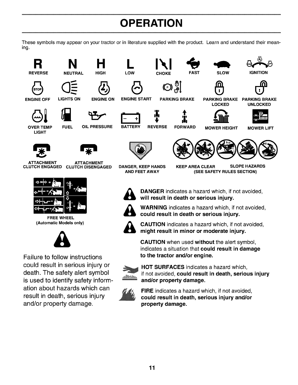
These symbols may appear on your tractor or in literature supplied with the product. Learn and understand their mean-
ing.
R N H L I'.,I
REVERSE NEUTRAL HIGH LOW CHOKE FAST SLOW IGNITION
ENGINE OFF LIGHTS ON ENGINE ON ENGINE START PARKING BRAKE PARKING BRAKE PARKING BRAKE
LOCKED UNLOCKED
OVER TEMP FUEL OIL PRESSURE BATTERY REVERSE FORWARD MOWER HEIGHT MOWER LIFT
LIGHT
ATTACHMENT
CLUTCH ENGAGED ATTACHMENT
CLUTCH DISENGAGED DANGER, KEEP HANDS
AND FEET AWAY
KEEP AREA CLEAR SLOPE HAZARDS
(SEE SAFETY RULES SECTION)
FREE WHEEL
(Automatic Models only)
Failure to follow instructions
could result in serious injury or
death. The safety alert symbol
is used to identify safety inform-
ation about hazards which can
result in death, serious injury
and/or property damage.
&
&
&
DANGER indicates a hazard which, if not avoided,
will result in death or serious injury.
WARNING indicates a hazard which, if not avoided,
could result in death or serious injury.
CAUTION indicates a hazard which, if not avoided,
might result in minor or moderate injury.
CAUTION when used without the alert symbol,
indicates a situation that could result in damage
to the tractor and/or engine.
HOT SURFACES indicates a hazard which,
if not avoided, could result in death, serious injury
and/or property damage.
FIRE indicates a hazard which, if not avoided,
could result in death, serious injury and/or
property damage.
11
OPERATION
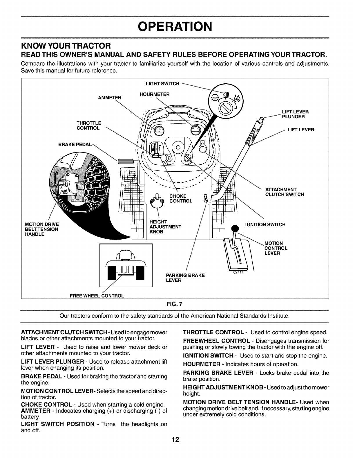
KNOW YOU R TRACTOR
READ THIS OWNER'S MANUAL AND SAFETY RULES BEFORE OPERATING YOUR TRACTOR.
Compare the illustrations with your tractor to familiarize yourself with the location of various controls and adjustments.
Save this manual for future reference.
AMMETER
LIGHT SWITCH
HOURMETER
THROTTLE
CONTROL
LIFT LEVER
PLUNGER
LIFT LEVER
BRAKE
s S
__ _s S
s
""" ~ ATTACHMENT
CHOKE CLUTCH SWITCH
CONTROL
MOTION DRIVE
BELTTENSION
HANDLE
HEIGHT
ADJUSTMENT
KNOB
IGNITION SWITCH
MOTION
CONTROL
LEVER
PARKING BRAKE
LEVER
02711
FREE WHEEL CONTROL
FIG. 7
Our tractors conform to the safety standards of the American National Standards Institute.
ATTACH MENT CLUTCH SWITCH - Used to engage mower
blades or other attachments mounted to your tractor.
LIFT LEVER - Used to raise and lower mower deck or
other attachments mounted to your tractor.
LIFT LEVER PLUNGER - Used to release attachment lift
lever when changing its position.
BRAKE PEDAL - Used for braking the tractor and starting
the engine.
MOTION CONTROL LEVER- Selects the speed and direc-
tion of tractor.
CHOKE CONTROL - Used when starting a cold engine.
AMMETER - Indocates charging (+) or discharging (-) of
battery.
LIGHT SWITCH POSITION - Turns the headlights on
and off.
THROTTLE CONTROL - Used to control engine speed.
FREEWHEEL CONTROL - Disengages transmission for
pushing or slowly towing the tractor with the engine off.
IGNITION SWITCH - Used to start and stop the engine.
HOURMETER - Indicates hours of operation.
PARKING BRAKE LEVER - Locks brake pedal into the
brake position.
H EIGHT ADJUSTMENT KNOB - Used to adjust the mower
height.
MOTION DRIVE BELT TENSION HANDLE- Used when
changing motion drive belt and, if necessary, starting engine
under extremely cold conditions.
12
OPERATION
The operation of any tractor can result in foreign objects thrown into the eyes, which can result
in severe eye damage. Always wear safety glasses or eye shields while operating your trac-
tor or performing any adjustments or repairs. We recommend a wide vision safety mask over
spectacles or standard safety glasses.
HOW TO USE YOUR TRACTOR
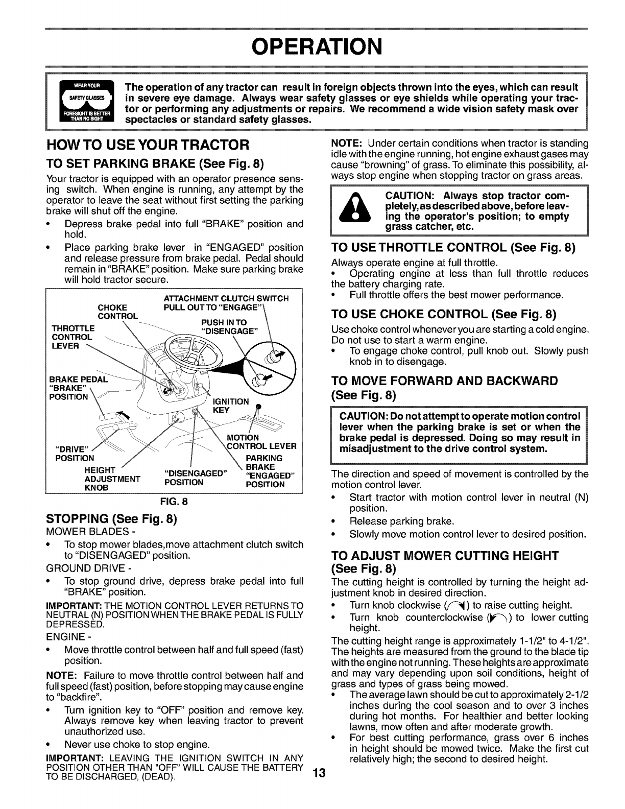
TO SET PARKING BRAKE (See Fig. 8)
Your tractor is equipped with an operator presence sens-
ing switch. When engine is running, any attempt by the
operator to leave the seat without first setting the parking
brake will shut off the engine.
° Depress brake pedal into full "BRAKE" position and
hold.
° Place parking brake lever in "ENGAGED" position
and release pressure from brake pedal. Pedal should
remain in "BRAKE" position. Make sure parking brake
will hold tractor secure.
ATTACHMENT CLUTCH SWITCH
CHOKE PULL OUTTO "ENGAGE"'
CONTROL PUSH IN TO
THROTTLE _ "DISENGAGE"
CONTROL
LEVER
BRAKE PEDAL
"BRAKE"
MOTION
"DRIVE" LEVER
POSITION PARKING
BRAKE
HEIGHT "DISENGAGED" "ENGAGED"
ADJUSTMENT POSITION POSITION
KNOB
FIG. 8
STOPPING (See Fig. 8)
MOWER BLADES -
• To stop mower blades,move attachment clutch switch
to "DISENGAGED" position.
GROUND DRIVE -
• To stop ground drive, depress brake pedal into full
"BRAKE" position.
IMPORTANT: THE MOTION CONTROL LEVER RETURNSTO
NEUTRAL (N) POSITIONWHEN THE BRAKE PEDAL IS FULLY
DEPRESSED.
ENGINE -
• Move throttle control between half and full speed (fast)
position.
NOTE: Failure to move throttle control between half and
full speed (fast) position, before stopping may cause engine
to "backfire".
• Turn ignition key to "OFF" position and remove key.
Always remove key when leaving tractor to prevent
unauthorized use.
• Never use choke to stop engine.
IMPORTANT: LEAVING THE IGNITION SWITCH IN ANY
POSITION OTHER THAN "OFF" WILL CAUSETHE BATTERY
TO BE DISCHARGED, (DEAD).
NOTE: Under certain conditions when tractor is standing
idle with the engine running, hot engine exhaust gases may
cause "browning" of grass. To eliminate this possibility, al-
ways stop engine when stopping tractor on grass areas.
&CAUTION: Always stop tractor com-
pletely, as described above, before leav-
ing the operator's position; to empty
grass catcher, etc.
TO USE THROTTLE CONTROL (See Fig. 8)
Always operate engine at full throttle.
• Operating engine at less than full throttle reduces
the battery charging rate.
• Full throttle offers the best mower performance.
TO USE CHOKE CONTROL (See Fig. 8)
Use choke control whenever you are starting a cold engine.
Do not use to start a warm engine.
• To engage choke control, pull knob out. Slowly push
knob in to disengage.
TO MOVE FORWARD AND BACKWARD
(See Fig. 8)
CAUTION: Do not attempt to operate motion control
lever when the parking brake is set or when the
brake pedal is depressed. Doing so may result in
misadjustment to the drive control system.
13
The direction and speed of movement is controlled by the
motion control lever.
• Start tractor with motion control lever in neutral (N)
position.
• Release parking brake.
• Slowly move motion control lever to desired position.
TO ADJUST MOWER CUTTING HEIGHT
(See Fig. 8)
The cutting height is controlled by turning the height ad-
justment knob in desired direction.
• Turn knob clockwise (F_I) to raise cutting height.
• Turn knob counterclockwise (_) to lower cutting
height.
The cutting height range is approximately 1-1/2" to 4-1/2".
The heights are measured from the ground to the blade tip
with the engine not running. These heights are approximate
and may vary depending upon soil conditions, height of
grass and types of grass being mowed.
• The average lawn should be cut to approximately 2-1/2
inches during the cool season and to over 3 inches
during hot months. For healthier and better looking
lawns, mow often and after moderate growth.
• For best cutting performance, grass over 6 inches
in height should be mowed twice. Make the first cut
relatively high; the second to desired height.
OPERATION
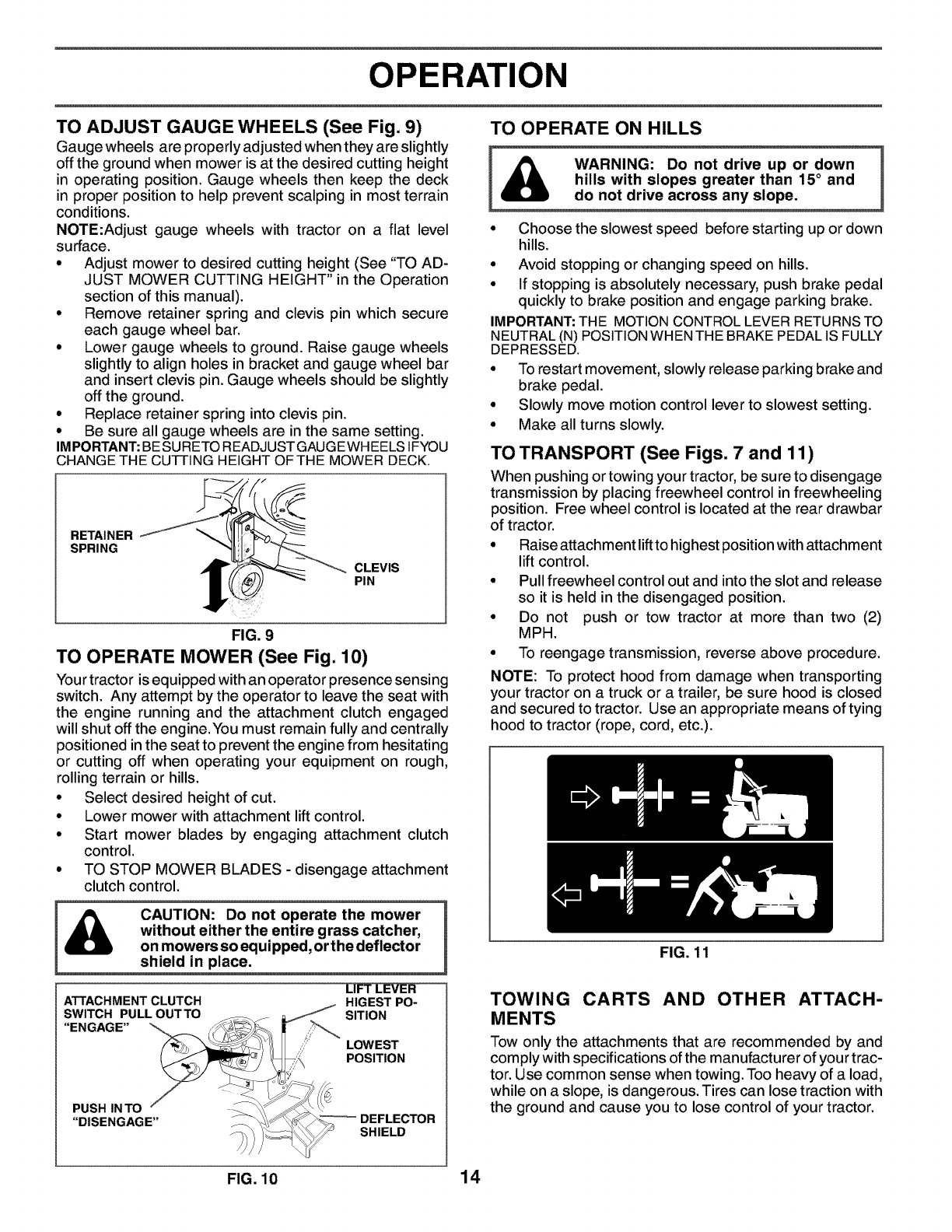
TO ADJUST GAUGE WHEELS (See Fig. 9)
Gauge wheels are properly adjusted when they are slightly
off the ground when mower is at the desired cutting height
in operating position. Gauge wheels then keep the deck
in proper position to help prevent scalping in most terrain
conditions.
NOTE:Adjust gauge wheels with tractor on a flat level
surface.
• Adjust mower to desired cutting height (See "TO AD-
JUST MOWER CUTTING HEIGHT" in the Operation
section of this manual).
• Remove retainer spring and clevis pin which secure
each gauge wheel bar.
• Lower gauge wheels to ground. Raise gauge wheels
slightly to align holes in bracket and gauge wheel bar
and insert clevis pin. Gauge wheels should be slightly
off the ground.
• Replace retainer spring into clevis pin.
• Be sure all gauge wheels are in the same setting.
IMPORTANT:BESURETO READJUSTGAUGEWHEELSIFYOU
CHANGE THE CUTTING HEIGHT OF THE MOWER DECK.
RETAINER
SPRING
CLEVIS
PIN
FIG. 9
TO OPERATE MOWER (See Fig. 10)
Your tractor is equipped with an operator presence sensing
switch. Any attempt by the operator to leave the seat with
the engine running and the attachment clutch engaged
will shut off the engine.You must remain fully and centrally
positioned in the seat to prevent the engine from hesitating
or cutting off when operating your equipment on rough,
rolling terrain or hills.
• Select desired height of cut.
• Lower mower with attachment lift control.
• Start mower blades by engaging attachment clutch
control.
• TO STOP MOWER BLADES - disengage attachment
clutch control.
CAUTION: Do not operate the mower
without either the entire grass catcher,
on mowers so equipped, orthe deflector
shield in place.
ATTACHMENT CLUTCH
SWITCH PULL OUTTO
"ENGAGE"
LIFT LEVER
HIGEST PO-
SITION
LOWEST
POSITION
PUSH IN TO
"DISENGAGE" SHIELD
TO OPERATE ON HILLS
WARNING: Do not drive up or down
hills with slopes greater than 15° and
do not drive across any slope.
• Choose the slowest speed before starting up or down
hills.
• Avoid stopping or changing speed on hills.
• If stopping is absolutely necessary, push brake pedal
quickly to brake position and engage parking brake.
IMPORTANT:THE MOTION CONTROL LEVER RETURNSTO
NEUTRAL (N) POSITIONWHEN THE BRAKE PEDAL IS FULLY
DEPRESSED.
• To restart movement, slowly release parking brake and
brake pedal.
• Slowly move motion control lever to slowest setting.
• Make all turns slowly.
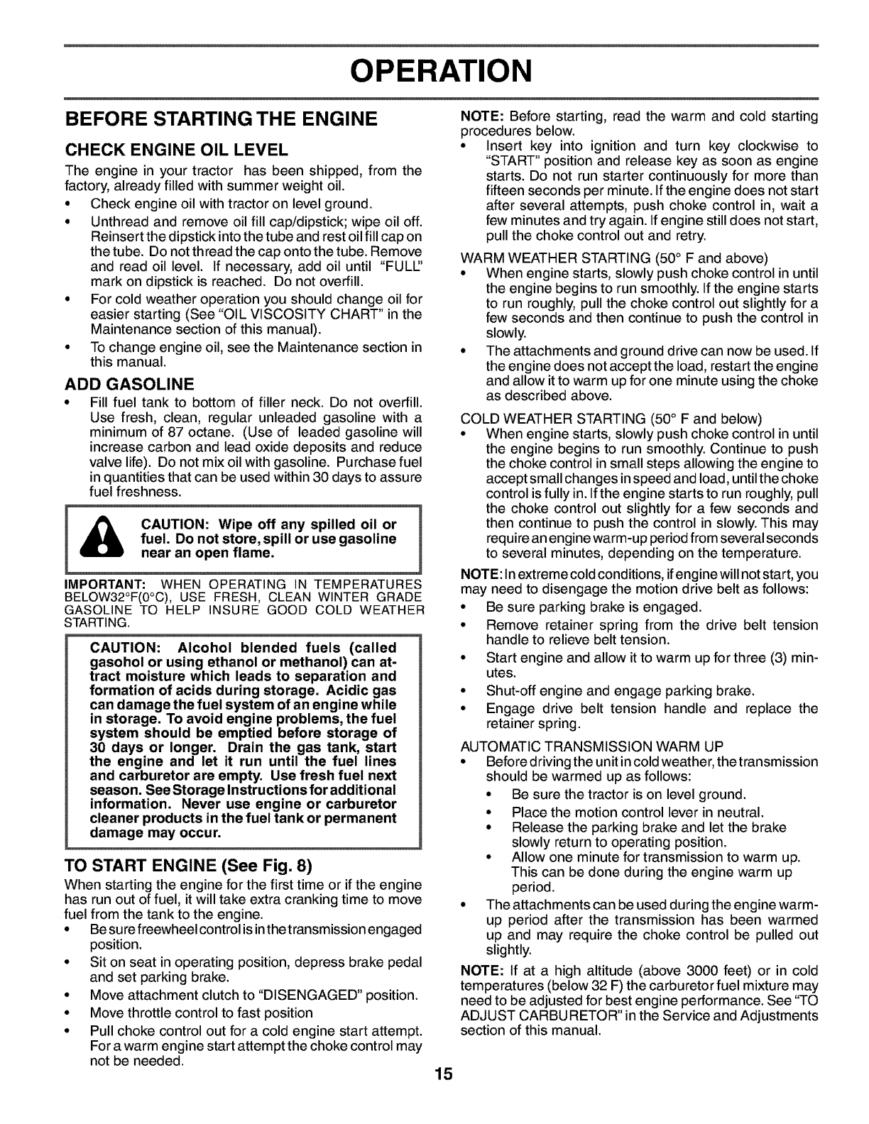
TO TRANSPORT (See Figs. 7 and 11)
When pushing or towing your tractor, be sure to disengage
transmission by placing freewheel control in freewheeling
position. Free wheel control is located at the rear drawbar
of tractor.
• Raise attachment liftto highest position with attachment
lift control.
• Pull freewheel control out and into the slot and release
so it is held in the disengaged position.
• Do not push or tow tractor at more than two (2)
MPH.
• To reengage transmission, reverse above procedure.
NOTE: To protect hood from damage when transporting
your tractor on a truck or a trailer, be sure hood is closed
and secured to tractor. Use an appropriate means of tying
hood to tractor (rope, cord, etc.).
FIG. 11
TOWING CARTS AND OTHER ATTACH-
MENTS
Tow only the attachments that are recommended by and
comply with specifications of the manufacturer of your trac-
tor. Use common sense when towing. Too heavy of a load,
while on a slope, is dangerous. Tires can lose traction with
the ground and cause you to lose control of your tractor.
FIG. 10 14
OPERATION
BEFORE STARTING THE ENGINE
CHECK ENGINE OIL LEVEL
The engine in your tractor has been shipped, from the
factory, already filled with summer weight oil.
• Check engine oil with tractor on level ground.
• Unthread and remove oil fill cap/dipstick; wipe oil off.
Reinsert the dipstick into the tube and rest oil fill cap on
the tube. Do not thread the cap onto the tube. Remove
and read oil level. If necessary, add oil until "FULL'
mark on dipstick is reached. Do not overfill.
• For cold weather operation you should change oil for
easier starting (See "OIL VISCOSITY CHART" in the
Maintenance section of this manual).
• To change engine oil, see the Maintenance section in
this manual.
ADD GASOLINE
• Fill fuel tank to bottom of filler neck. Do not overfill.
Use fresh, clean, regular unleaded gasoline with a
minimum of 87 octane. (Use of leaded gasoline will
increase carbon and lead oxide deposits and reduce
valve life). Do not mix oil with gasoline. Purchase fuel
in quantities that can be used within 30 days to assure
fuel freshness.
CAUTION: Wipe off any spilled oil or
fuel. Do not store, spill or use gasoline
near an open flame.
IMPORTANT: WHEN OPERATING IN TEMPERATURES
BELOW32°F(0°C), USE FRESH, CLEAN WINTER GRADE
GASOLINE TO HELP INSURE GOOD COLD WEATHER
STARTING.
CAUTION: Alcohol blended fuels (called
gasohol or using ethanol or methanol) can at-
tract moisture which leads to separation and
formation of acids during storage. Acidic gas
can damage the fuel system of an engine while
in storage. To avoid engine problems, the fuel
system should be emptied before storage of
30 days or longer. Drain the gas tank, start
the engine and let it run until the fuel lines
and carburetor are empty. Use fresh fuel next
season. See Storage Instructions for additional
information. Never use engine or carburetor
cleaner products in the fuel tank or permanent
damage may occur.
TO START ENGINE (See Fig. 8)
When starting the engine for the first time or if the engine
has run out of fuel, it will take extra cranking time to move
fuel from the tank to the engine.
• Be sure freewheel control is inthetransmission engaged
position.
• Sit on seat in operating position, depress brake pedal
and set parking brake.
• Move attachment clutch to "DISENGAGED" position.
• Move throttle control to fast position
• Pull choke control out for a cold engine start attempt.
For a warm engine start attempt the choke control may
not be needed.
NOTE: Before starting, read the warm and cold starting
procedures below.
• Insert key into ignition and turn key clockwise to
"START" position and release key as soon as engine
starts. Do not run starter continuously for more than
fifteen seconds per minute. If the engine does not start
after several attempts, push choke control in, wait a
few minutes and try again. If engine still does not start,
pull the choke control out and retry.
WARM WEATHER STARTING (50° F and above)
• When engine starts, slowly push choke control in until
the engine begins to run smoothly. If the engine starts
to run roughly, pull the choke control out slightly for a
few seconds and then continue to push the control in
slowly.
• The attachments and ground drive can now be used. If
the engine does not accept the load, restart the engine
and allow it to warm up for one minute using the choke
as described above.
COLD WEATHER STARTING (50 ° F and below)
• When engine starts, slowly push choke control in until
the engine begins to run smoothly. Continue to push
the choke control in small steps allowing the engine to
accept small changes in speed and load, until the choke
control is fully in. If the engine starts to run roughly, pull
the choke control out slightly for a few seconds and
then continue to push the control in slowly. This may
require an engine warm-up period from several seconds
to several minutes, depending on the temperature.
NOTE: In extreme cold conditions, if engine will not start, you
may need to disengage the motion drive belt as follows:
• Be sure parking brake is engaged.
• Remove retainer spring from the drive belt tension
handle to relieve belt tension.
• Start engine and allow it to warm up for three (3) min-
utes.
• Shut-off engine and engage parking brake.
• Engage drive belt tension handle and replace the
retainer spring.
AUTOMATIC TRANSMISSION WARM UP
° Before driving the unit in cold weather, the transmission
should be warmed up as follows:
• Be sure the tractor is on level ground.
• Place the motion control lever in neutral.
• Release the parking brake and let the brake
slowly return to operating position.
• Allow one minute for transmission to warm up.
This can be done during the engine warm up
period.
• The attachments can be used during the engine warm-
up period after the transmission has been warmed
up and may require the choke control be pulled out
slightly.
NOTE: If at a high altitude (above 3000 feet) or in cold
temperatures (below 32 F) the carburetor fuel mixture may
need to be adjusted for best engine performance. See "TO
ADJUST CARBURETOR" in the Service and Adjustments
section of this manual.
15
OPERATION
PURGE TRANSMISSION
CAUTION: Never engage or disengage
freewheel lever while the engine is run-
ning.
To ensure proper operation and performance, it is recom-
mended that the transmission be purged before operating
tractor for the first time. This procedure will remove any
trapped air inside the transmission which may have de-
veloped during shipping of your tractor.
IMPORTANT: SHOULD YOUR TRANSMISSION REQUIRE
REMOVAL FOR SERVICE OR REPLACEMENT, IT SHOULD
BE PURGED AFTER REINSTALLATIONBEFORE OPERATING
THE TRACTOR.
• Place tractor safely on level surface with engine off and
parking brake set.
• Disengage transmission by placing freewheel control
in freewheeling position (See"TO TRANSPORT" in this
section of manual).
• Sitting in the tractor seat, start engine. After the en-
gine is running, move throttle control to slow position.
Disengage parking brake
• Move motion control lever to full forward position and
hold for five (5) seconds. Move lever to full reverse
position and hold for five (5) seconds. Repeat this
procedure three (3) times.
NOTE: During this procedure there will be no movement
of drive wheels. The air is being removed from hydraulic
drive system.
• Move motion control lever to neutral (N) position. Shut-
off engine and set parking brake.
• Engage transmission by placing freewheel control in
driving position (See "TO TRANSPORT" in this section
of manual).
• Sitting inthe tractor seat, start engine. After the engine
is running, move throttle control to half (1/2) speed.
Disengage parking brake.
• Slowly move motion control lever forward, after the
tractor moves approximately five (5) feet, slowly move
motion control lever to reverse position. After the trac-
tor moves approximately five (5) feet return the mo-
tion control lever to the neutral (N) position. Repeat
this procedure with the motion control lever three (3)
times.
• Your transmission is now purged and now ready for
normal operation.
MOWING TIPS
• Tire chains cannot be used when the mower housing
is attached to tractor.
• Mower should be properly leveled for best mowing
performance. See "TO LEVEL MOWER HOUSING" in
the Service and Adjustments section of this manual.
• The left hand side of mower should be used for trim-
ming.
• Drive so that clippings are discharged onto the area
that has been cut. Have the cut area to the right of
the tractor. This will result in a more even distribution
of clippings and more uniform cutting.
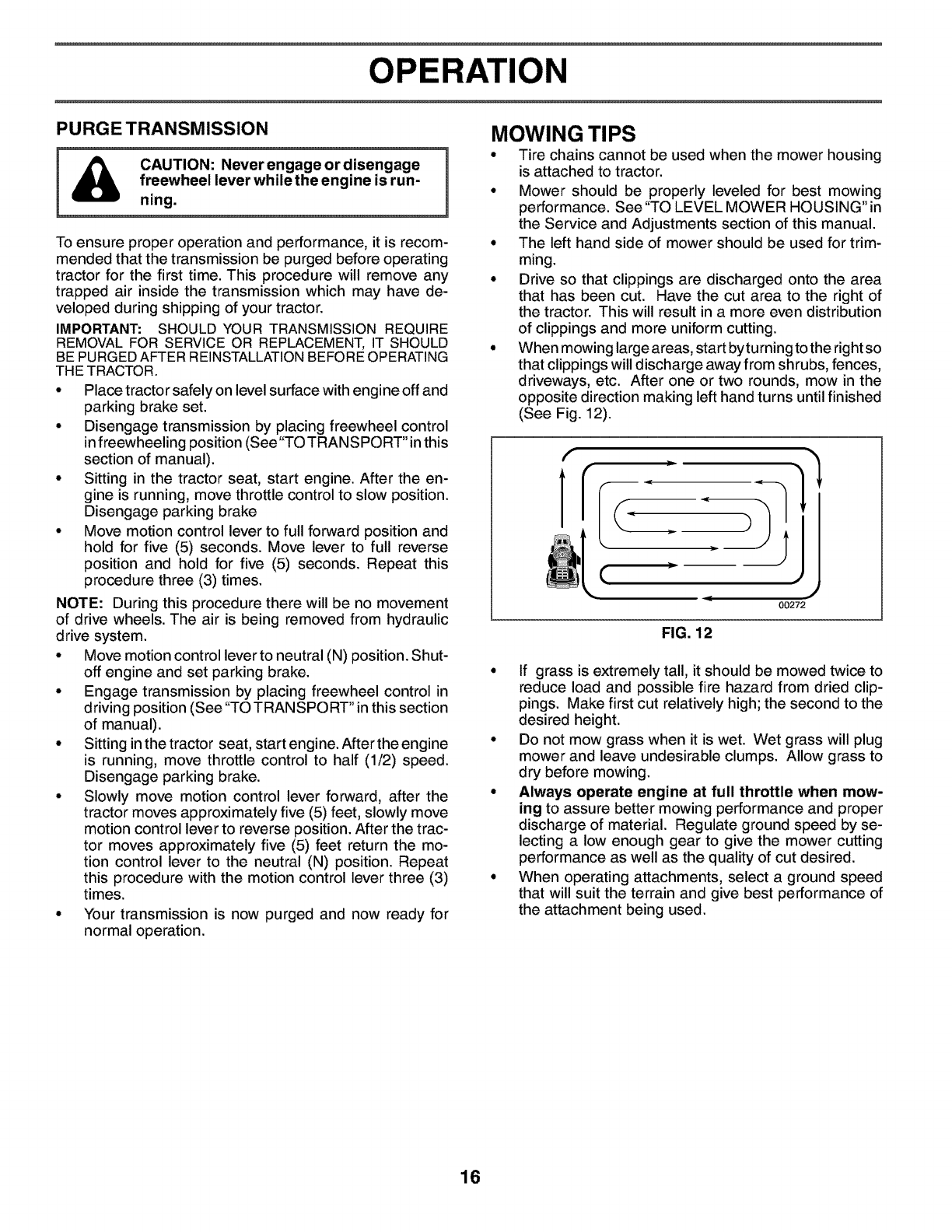
• When mowing large areas, start byturning to the right so
that clippings will discharge away from shrubs, fences,
driveways, etc. After one or two rounds, mow in the
opposite direction making left hand turns until finished
(See Fig. 12).
f
(
,. <J
00272
FIG. 12
• If grass is extremely tall, it should be mowed twice to
reduce load and possible fire hazard from dried clip-
pings. Make first cut relatively high; the second to the
desired height.
• Do not mow grass when it is wet. Wet grass will plug
mower and leave undesirable clumps. Allow grass to
dry before mowing.
•Always operate engine at full throttle when mow-
ing to assure better mowing performance and proper
discharge of material. Regulate ground speed by se-
lecting a low enough gear to give the mower cutting
performance as well as the quality of cut desired.
• When operating attachments, select a ground speed
that will suit the terrain and give best performance of
the attachment being used.
16
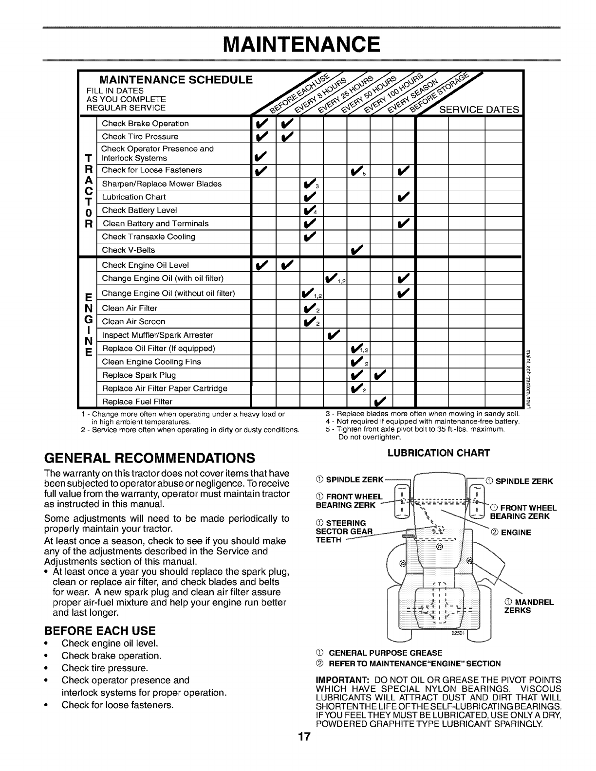
Check Brake Operation !_ !_
Check Tire Pressure V' V'
Check Operator Presence and
TInterlock Systems V'
RCheck for Loose Fasteners I_ !_'5
Sharpen/Replace Mower Blades V'3
TLubrication Chart I_ !_
0Check Battery Level _4
RClean Battery and Terminals II_ II_
Check Transaxle Cooling V'
Check V-Belts t_
Check Engine Oil Level !l_ Vp
Change Engine Oil (with oil filter) _1,2
EChange Engine Oil (without oil filter) !_1,2 !i_
N Clean Air Filter !_2
GClean Air Screen Vi2
NI Inspect Muffler/Spark Arrester v'
EReplace Oil Filter (If equipped) t_>2
Clean Engine Cooling Fins I_ 2
Replace Spark Plug II_ V'
Replace Air Filter Paper Cartridge t1_2
Replace Fuel Filter
1 - Change more often when operating under a heavy load or
in high ambient temperatures,
2 - Service more often when operating in dirty or dusty conditions,
3 - Replace blades more often when mowing in sandy soil,
4 - Not required if equipped with maintenance-free battery,
5 - Tighten front axle pivot bolt to 35 ff,-Ibs, maximum,
Do not overtighten,
GENERAL RECOMMENDATIONS
The warranty on this tractor does not cover items that have
been subjected to operator abuse or negligence. Toreceive
full value from the warranty, operator must maintain tractor
as instructed in this manual.
Some adjustments will need to be made periodically to
properly maintain your tractor.
At least once a season, check to see if you should make
any of the adjustments described in the Service and
Adjustments section of this manual.
• At least once a year you should replace the spark plug,
clean or replace air filter, and check blades and belts
for wear. A new spark plug and clean air filter assure
proper air-fuel mixture and help your engine run better
and last longer.
LUBRICATION CHART
OS
OFRONT WHEEL
BEARING ZERK
OSTEERING
SECTOR GEAR
TEETH
"O SPINDLE ZERK
FRONT WHEEL
BEARING ZERK
ENGINE
OMANDREL
ZERKS
BEFORE EACH USE
• Check engine oil level.
• Check brake operation.
• Check tire pressure.
• Check operator presence and
interlock systems for proper operation.
• Check for loose fasteners.
02501
17
OGENERAL PURPOSE GREASE
@REFERTO MAINTENANCE"ENGINE"SECTION
IMPORTANT: DO NOT OIL OR GREASE THE PIVOT POINTS
WHICH HAVE SPECIAL NYLON BEARINGS. VISCOUS
LUBRICANTS WILL ATTRACT DUST AND DIRT THAT WILL
SHORTENTHE LIFE OFTHE SELF-LUBRICATING BEARINGS.
IFYOU FEELTHEY MUST BE LUBRICATED, USE ONLY A DRY,
POWDERED GRAPHITE TYPE LUBRICANT SPARINGLY.
MAINTENANCE
TRACTOR
Always observe safety rules when performing any main-
tenance.
BRAKE OPERATION
If tractor requires more than six (6) feet stopping distance
at high speed in highest gear, then brake must be adjusted.
(See"TO ADJUST BRAKE" in the Service and Adjustments
section of this manual).
TIRES
•Maintain proper air pressure in all tires (See"PRODUCT
SPECIFICATIONS" section of this manual).
• Keep tires free of gasoline, oil, or insect control chemi-
cals which can harm rubber.
• Avoid stumps, stones, deep ruts, sharp objects and
other hazards that may cause tire damage.
NOTE: To seal tire punctures and prevent flat tires due to
slow leaks, tire sealant may be purchased from your local
parts dealer. Tire sealant also prevents tire dry rot and
corrosion.
OPERATOR PRESENCE SYSTEM
Be sure operator presence and interlock systems are work-
ing properly. If your tractor does not function as described,
repair the problem immediately.
•The engine should not start unless the brake pedal is
fully depressed and attachement clutch control is in
the disengaged position.
•When the engine is running, any attempt bythe operator
to leave the seat without first setting the parking brake
should shut off the engine.
•When the engine is running and the attachment clutch
is engaged, any attempt by the operator to leave the
seat should shut off the engine.
•The attachment clutch should never operate unless
the operator is in the seat..
BLADE CARE
For best results mower blades must be kept sharp. Replace
bent or damaged blades.
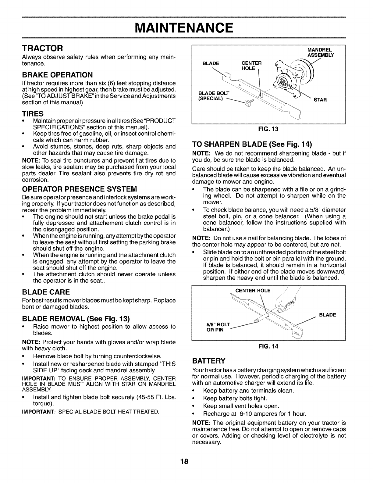
BLADE REMOVAL (See Fig. 13)
•Raise mower to highest position to allow access to
blades.
NOTE: Protect your hands with gloves and/or wrap blade
with heavy cloth.
• Remove blade bolt by turning counterclockwise.
• Install new or resharpened blade with stamped "THIS
SIDE UP" facing deck and mandrel assembly.
IMPORTANT: TO ENSURE PROPER ASSEMBLY, CENTER
HOLE IN BLADE MUST ALIGN WITH STAR ON MANDREL
ASSEMBLY.
• Install and tighten blade bolt securely (45-55 Ft. Lbs.
torque).
IMPORTANT: SPECIAL BLADE BOLT HEATTREATED.
BLADE CENTER
HOLE
MANDREL
ASSEMBLY
BLADE BOLT
(SPECIAL) _-_ _:._ STAR
FIG. 13
TO SHARPEN BLADE (See Fig. 14)
NOTE: We do not recommend sharpening blade -but if
you do, be sure the blade is balanced.
Care should be taken to keep the blade balanced. An un-
balanced blade willcause excessive vibrationand eventual
damage to mower and engine.
•The blade can be sharpened with a file or on a grind-
ing wheel. Do not attempt to sharpen while on the
mower.
• To check blade balance, you will need a 5/8" diameter
steel bolt, pin, or a cone balancer. (When using a
cone balancer, follow the instructions supplied with
balancer.)
NOTE: Do not use a nail for balancing blade. The lobes of
the center hole may appear to be centered, but are not.
• Slide blade on to an unthreaded portion of the steel bolt
or pin and hold the bolt or pin parallel with the ground.
If blade is balanced, it should remain in a horizontal
position. If either end of the blade moves downward,
sharpen the heavy end until the blade is balanced.
CENTER HOLE
5/8" BOLT
OR PIN
BLADE
FIG. 14
BATTERY
Your tractor has a battery chargingsystem which issufficient
for normal use. However, periodic charging of the battery
with an automotive charger will extend its life.
°Keep battery and terminals clean.
°Keep battery bolts tight.
°Keep small vent holes open.
°Recharge at 6-10 amperes for 1 hour.
NOTE: The original equipment battery on your tractor is
maintenance free. Do not attempt to open or remove caps
or covers. Adding or checking level of electrolyte is not
necessary.
18
MAINTENANCE
TO CLEAN BATTERY AND TERMINALS
Corrosion and dirt on the battery and terminals can cause
the battery to "leak" power.
• Remove terminal guard.
• Disconnect BLACK battery cable first then RED bat-
tery cable and remove battery from tractor.
• Rinse the battery with plain water and dry.
• Clean terminals and battery cable ends with wire brush
until bright.
• Coat terminals with grease or petroleum jelly.
• Reinstall battery (See "REPLACING BATTERY" in
the SERVICE AND ADJUSTMENTS section of this
manual).
V-BELTS
Check V-belts for deterioration and wear after 100 hours
of operation and replace if necessary. The belts are not
adjustable. Replace belts if they begin to slip from wear.
TRANSAXLE COOLING
The transmission fan and cooling fins should be kept clean
to assure proper cooling.
Do not attempt to clean fan or transmission while engine
is running or while the transmission is hot. To prevent pos-
sible damage to seals, do not use high pressure water or
steam to clean transaxle.
• Inspect cooling fan to be sure fan blades are intact and
clean.
• Inspect cooling fins for dirt, grass clippings and other
materials. To prevent damage to seals, do not use
compressed air or high pressure sprayer to clean cool-
ing fins.
TRANSAXLE PUMP FLUID
The transaxle was sealed at the factory and fluid mainte-
nance is not required for the life of the transaxle. Should
the transaxle ever leak or require servicing, contact your
nearest authorized service center/department.
ENGINE
LUBRICATION
Only use high quality detergent oil rated with API service
classification SF-SJ. Select the oil's SAE viscosity grade
according to your expected operating temperature
SAE VISCOSITY GRADES
F -20 0 30 32 40 60 80 100
c-do -20 -4 ;;o 20 ;0 4;
TEMPERATURE RANGE ANTICIPATED BEFORE NEXT OIL CHANGE
oi_ yisc chart4 e
FIG. 15
Change the oil after every 50 hours of operation or at least
once a year if the tractor is not used for 50 hours in one
year.
Check the crankcase oil level before starting the engine
and after each eight (8) hours of operation.
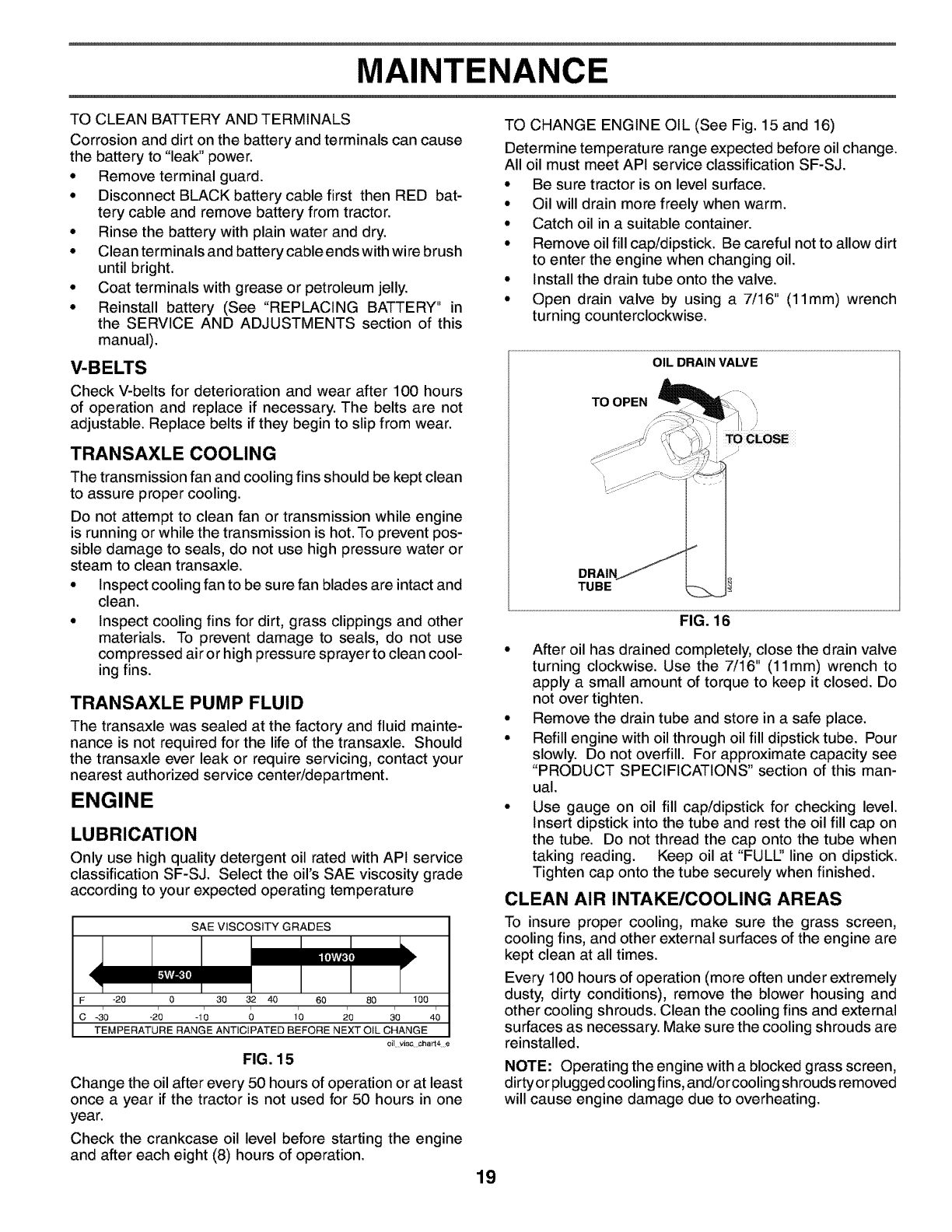
TO CHANGE ENGINE OIL (See Fig. 15 and 16)
Determine temperature range expected before oil change.
All oil must meet API service classification SF-SJ.
• Be sure tractor is on level surface.
• Oil will drain more freely when warm.
• Catch oil in a suitable container.
• Remove oil fill cap/dipstick. Be careful not to allow dirt
to enter the engine when changing oil.
• Install the drain tube onto the valve.
• Open drain valve by using a 7/16" (11mm) wrench
turning counterclockwise.
OIL DRAIN VALVE
TO OPEN
TUBE
TO CLOSE
FIG. 16
• After oil has drained completely, close the drain valve
turning clockwise. Use the 7/16" (11mm) wrench to
apply a small amount of torque to keep it closed. Do
not over tighten.
• Remove the drain tube and store in a safe place.
• Refill engine with oil through oil fill dipstick tube. Pour
slowly. Do not overfill. For approximate capacity see
"PRODUCT SPECIFICATIONS" section of this man-
ual.
• Use gauge on oil fill cap/dipstick for checking level.
Insert dipstick into the tube and rest the oil fill cap on
the tube. Do not thread the cap onto the tube when
taking reading. Keep oil at "FULl" line on dipstick.
Tighten cap onto the tube securely when finished.
CLEAN AIR INTAKE/COOLING AREAS
To insure proper cooling, make sure the grass screen,
cooling fins, and other external surfaces of the engine are
kept clean at all times.
Every 100 hours of operation (more often under extremely
dusty, dirty conditions), remove the blower housing and
other cooling shrouds. Clean the cooling fins and external
surfaces as necessary. Make sure the cooling shrouds are
reinstalled.
NOTE: Operating the engine with a blocked grass screen,
dirtyor plugged cooling fins, and/or cooling shrouds removed
will cause engine damage due to overheating.
19
MAINTENANCE
CLEAN AIR SCREEN
Air screen must be kept free of dirt and chaff to prevent
engine damage from overheating. Clean with a wire brush
or compressed air to remove dirt and stubborn dried gum
fibers. See engine manual.
AIR FILTER
Your engine will not run properly using a dirty air filter.
Service air cleaner more often under dusty conditions. See
engine manual.
ENGINE OIL FILTER
Replace the engine oil filter every season or every other oil
change if the tractor is used more than 100 hours in one
year. See engine manual.
MUFFLER
Inspect and replace corroded muffler and spark arrester
(if equipped) as it could create a fire hazard and/or dam-
age.
SPARK PLUGS
Replace spark plugs at the beginning of each mowing
season or after every 100 hours of operation, whichever
occurs first. Spark plug type and gap setting are shown in
"PRODUCT SPECIFICATIONS" section of this manual.
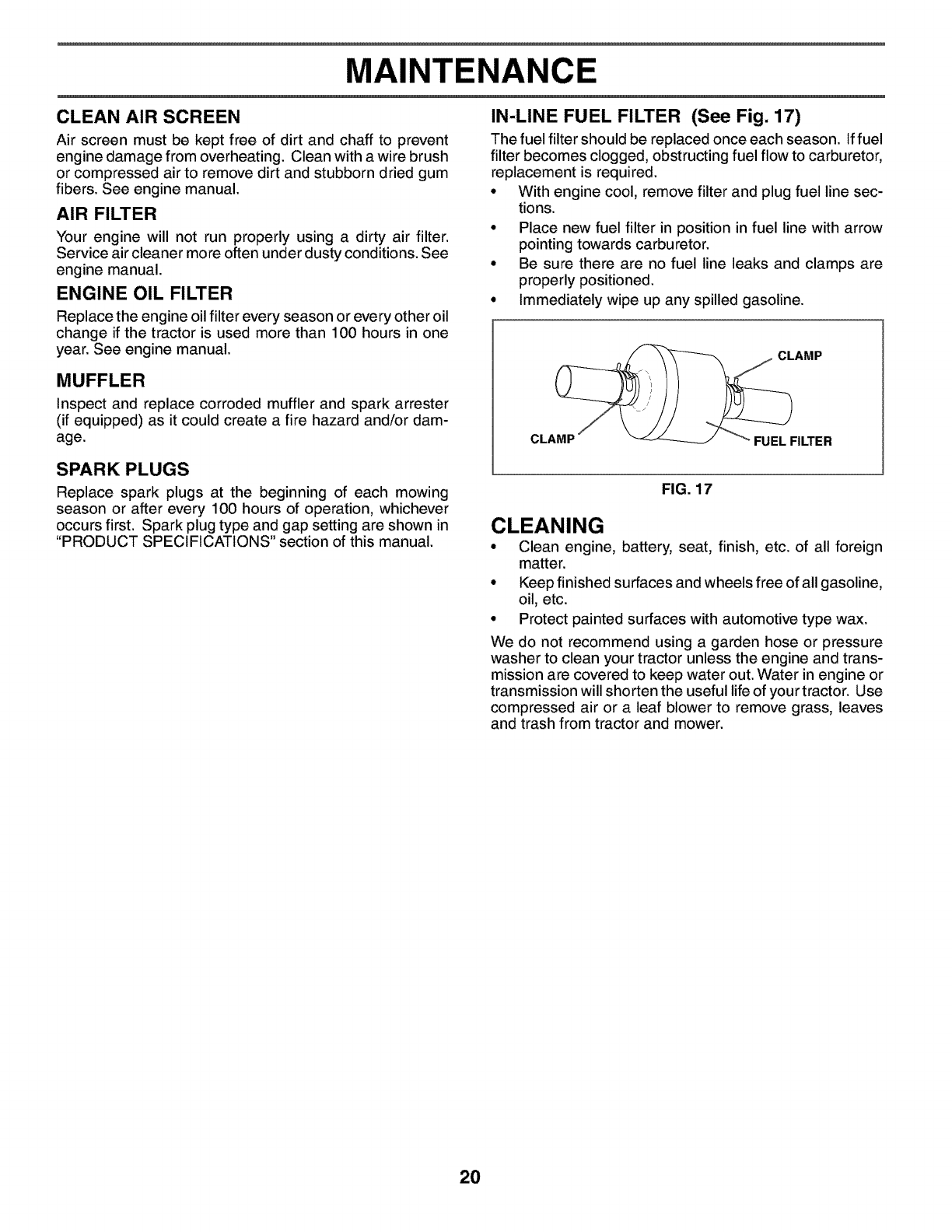
IN-LINE FUEL FILTER (See Fig. 17)
The fuel filter should be replaced once each season. Iffuel
filter becomes clogged, obstructing fuel flow to carburetor,
replacement is required.
• With engine cool, remove filter and plug fuel line sec-
tions.
• Place new fuel filter in position in fuel line with arrow
pointing towards carburetor.
• Be sure there are no fuel line leaks and clamps are
properly positioned.
• Immediately wipe up any spilled gasoline.
CLAMP
CLAMP FUEL FILTER
FIG. 17
CLEANING
• Clean engine, battery, seat, finish, etc. of all foreign
matter.
• Keep finished surfaces and wheels free of all gasoline,
oil, etc.
• Protect painted surfaces with automotive type wax.
We do not recommend using a garden hose or pressure
washer to clean your tractor unless the engine and trans-
mission are covered to keep water out. Water in engine or
transmission will shorten the useful life of your tractor. Use
compressed air or a leaf blower to remove grass, leaves
and trash from tractor and mower.
2O
SERVICE AND ADJUSTMENTS
WARNING: TO AVOID SERIOUS INJURY, BEFORE PERFORMING ANY SERVICE OR ADJUST-
MENTS:
Depress brake pedal fully and set parking brake.
Place attachment clutch in "DISENGAGED" position.
•Turn ignition key to "STOP" and remove key.
Make sure the blades and all moving parts have completely stopped.
Disconnect spark plug wire from spark plug and place wire where it cannot come in contact
with plug.
TRACTOR
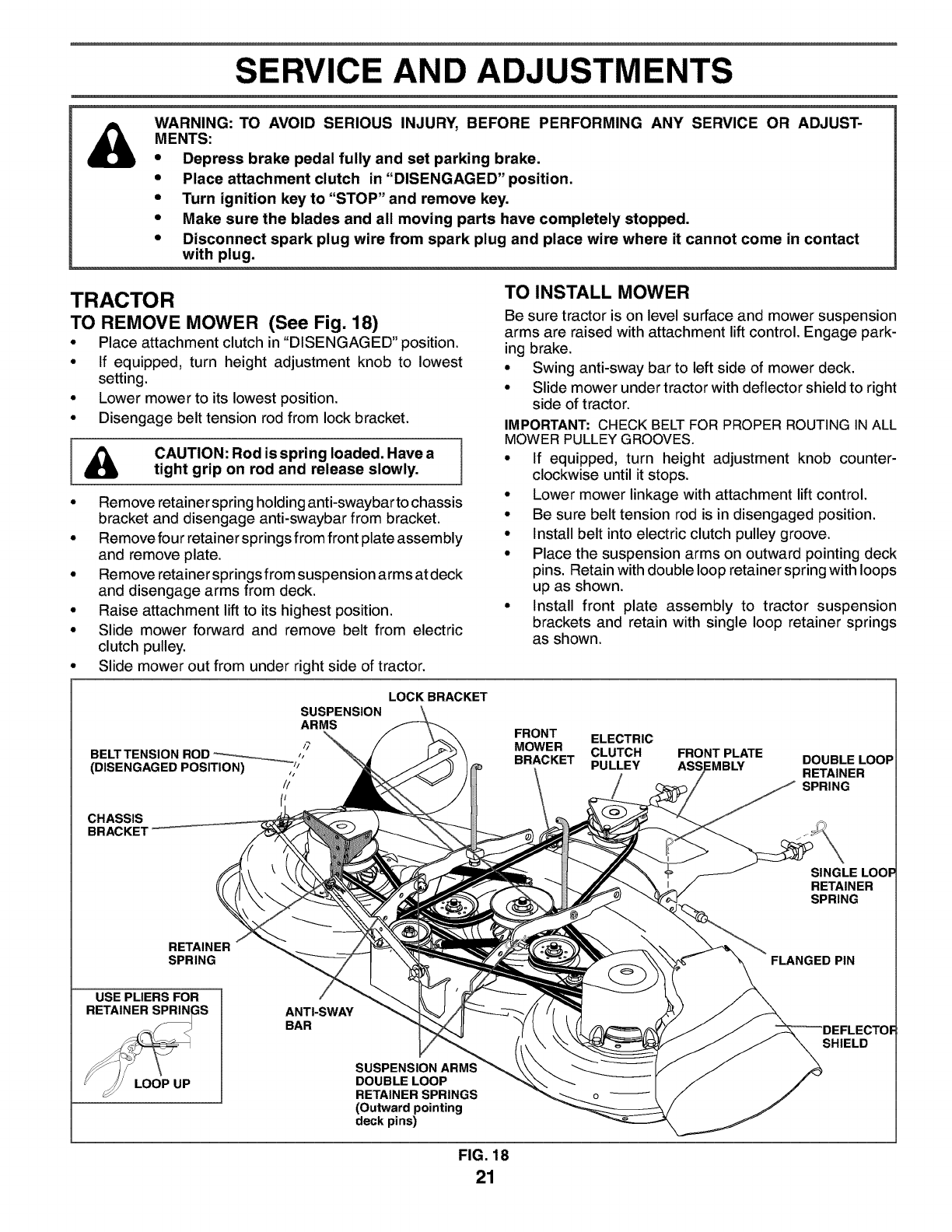
TO REMOVE MOWER (See Fig. 18)
•Place attachment clutch in "DISENGAGED" position.
• If equipped, turn height adjustment knob to lowest
setting.
• Lower mower to its lowest position.
• Disengage belt tension rod from lock bracket.
I _k CAUTION: Rod is spring loaded. Have atight grip on rod and release slowly.
• Remove retainer spring holding anti-swaybar to chassis
bracket and disengage anti-swaybar from bracket.
• Remove four retainer springs from front plate assembly
and remove plate.
• Remove retainer springs from suspension arms at deck
and disengage arms from deck.
• Raise attachment lift to its highest position.
• Slide mower forward and remove belt from electric
clutch pulley.
• Slide mower out from under right side of tractor.
TO INSTALL MOWER
Be sure tractor is on level surface and mower suspension
arms are raised with attachment lift control. Engage park-
ing brake.
• Swing anti-sway bar to left side of mower deck.
• Slide mower under tractor with deflector shield to right
side of tractor.
IMPORTANT: CHECK BELT FOR PROPER ROUTING IN ALL
MOWER PULLEY GROOVES.
• If equipped, turn height adjustment knob counter-
clockwise until it stops.
• Lower mower linkage with attachment lift control.
• Be sure belt tension rod is in disengaged position.
• Install belt into electric clutch pulley groove.
• Place the suspension arms on outward pointing deck
pins. Retain with double loop retainer spring with loops
up as shown.
• Install front plate assembly to tractor suspension
brackets and retain with single loop retainer springs
as shown.
LOCK BRACKET
SUSPENSION
ARMS
/7
BELT TENSION ROD --__ ,,
(DISENGAGED POSITION) ,i_j
//
FRONT ELECTRIC
MOWER CLUTCH
BRACKET PULLEY FRONT PLATE DOUBLE LOOP
RETAINER
SPRING
CHASSIS
BRACKE'r
RETAINER
SPRING
SINGLE
RETAINER
SPRING
FLANGED PIN
USE PLIERS FOR
RETAINER SPRIN_
LOOP UP
ANTI-SWAY
BAR
SUSPENSION ARMS
DOUBLE LOOP
RETAINER SPRINGS
(Outward pointing
deck pins)
o
FIG. 18
21
SHIELD
SERVICE AND ADJUSTMENTS
tPosition front plate assembly between front mower
brackets. Raise deck and plate assembly to align holes
and insert flanged pins. Secure pins with double loop
retainer springs between the plate assembly and mower
brackets.
NOTE: To assist in locating hole in flanged pin, the hole in
pin is inline with notch on head of pin. If necessary, move
mower side-to-side to give space between plate and mower
brackets.
IMPORTANT: CHECK BELT FOR PROPER ROUTING IN ALL
MOWER PULLEY GROOVES.
• Engage belt tension rod by pushing rod into locking
bracket.
CAUTION: Belt tension rod is spring
I loaded. Have a tight grip on rod and
slowly.
° Connect anti-sway bar to chassis bracket under left
footrest and retain with double loop retainer spring.
° If equipped, turn height adjustment knob clockwise to
remove slack from mower suspension.
° Raise deck to highest position.
TO LEVEL MOWER HOUSING
Adjust the mower while tractor is parked on level ground
or driveway. Make sure tires are properly inflated (See
"PRODUCT SPECIFICATIONS" section of this manual). If
tires are over or underinflated, you will not properly adjust
your mower.
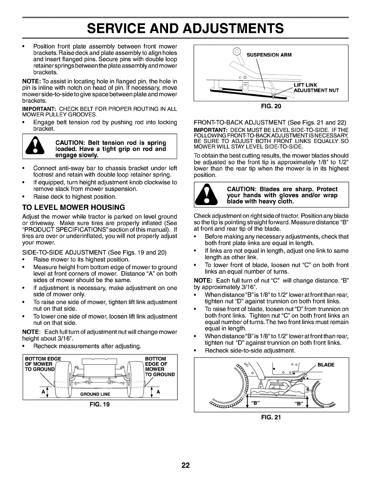
SIDE-TO-SIDE ADJUSTMENT (See Figs. 19 and 20)
• Raise mower to its highest position.
• Measure height from bottom edge of mower to ground
level at front corners of mower. Distance "A" on both
sides of mower should be the same.
• If adjustment is necessary, make adjustment on one
side of mower only.
• To raise one side of mower, tighten lift link adjustment
nut on that side.
• To lower one side of mower, loosen lift link adjustment
nut on that side.
NOTE: Each full turn of adjustment nut will change mower
height about 3/16".
° Recheck measurements after adjusting.
BOTTOM EDGE BOTTOM
MOWER _I- _ _ EDGE OF
OF
TOGROO.D/ /MOWER
FIG. 19
FIG. 20
FRONT-TO-BACK ADJUSTMENT (See Figs. 21 and 22)
IMPORTANT: DECK MUST BE LEVEL SI DE-TO-SI DE. IF THE
FOLLOWING FRONT-TO-BACK ADJ USTM ENT IS NECESSARY,
BE SURE TO ADJUST BOTH FRONT LINKS EQUALLY SO
MOWER WILL STAY LEVEL SI DE-TO-SIDE.
To obtain the best cutting results, the mower blades should
be adjusted so the front tip is approximately 1/8" to 1/2"
lower than the rear tip when the mower is in its highest
position.
CAUTION: Blades are sharp. Protect
your hands with gloves and/or wrap
blade with heavy cloth.
Check adjustment on right side oftractor. Position any blade
so the tip is pointing straight forward. Measure distance "B"
at front and rear tip of the blade.
• Before making any necessary adjustments, check that
both front plate links are equal in length.
• If links are not equal in length, adjust one link to same
length as other link.
• To lower front of blade, loosen nut "C" on both front
links an equal number of turns.
NOTE: Each full turn of nut "C" will change distance. "B"
by approximately 3/16".
• When distance"B"is 1/8" to 1/2" lower at front than rear,
tighten nut "D" against trunnion on both front links.
• To raise front of blade, loosen nut "D" from trunnion on
both front links. Tighten nut "C" on both front links an
equal number of turns.The two front links must remain
equal in length.
• When distance"B"is 1/8" to 1/2" lower at front than rear,
tighten nut "D" against trunnion on both front links.
• Recheck side-to-side adjustment.
.oj
A/o
FIG. 21
22
SERVICE AND ADJUSTMENTS
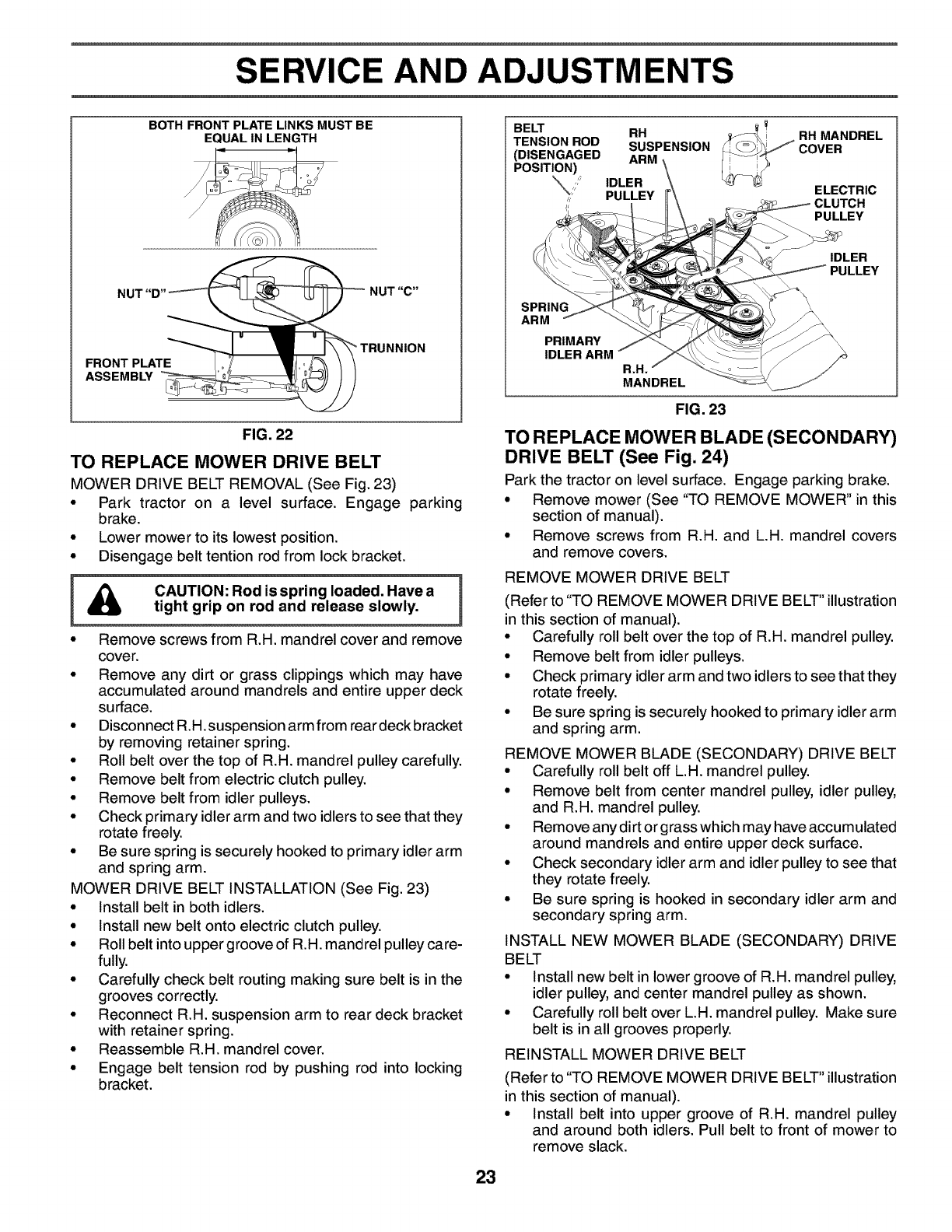
BOTH FRONT PLATE LINKS MUST BE
EQUAL IN LENGTH
NUT "C"
FRONT PLATE
ASSEMBLY _TRUNNION
FIG. 22
TO REPLACE MOWER DRIVE BELT
MOWER DRIVE BELT REMOVAL (See Fig. 23)
=Park tractor on a level surface. Engage parking
brake.
• Lower mower to its lowest position.
• Disengage belt tention rod from lock bracket.
HAC'°T'°"°°°ssprn°°a°e°"aveal
tight grip on rod and release slowly.
= =
, Remove screws from R.H. mandrel cover and remove
cover.
• Remove any dirt or grass clippings which may have
accumulated around mandrels and entire upper deck
surface.
• Disconnect R.H. suspension arm from rear deck bracket
by removing retainer spring.
• Roll belt over the top of R.H. mandrel pulley carefully.
• Remove belt from electric clutch pulley.
• Remove belt from idler pulleys.
• Check primary idler arm and two idlers to see that they
rotate freely.
• Be sure spring is securely hooked to primary idler arm
and spring arm.
MOWER DRIVE BELT INSTALLATION (See Fig. 23)
• Install belt in both idlers.
• Install new belt onto electric clutch pulley.
• Roll belt into upper groove of R.H. mandrel pulley care-
fully.
• Carefully check belt routing making sure belt is in the
grooves correctly.
• Reconnect R.H. suspension arm to rear deck bracket
with retainer spring.
• Reassemble R.H. mandrel cover.
• Engage belt tension rod by pushing rod into locking
bracket.
BELT RH
TENSION ROD SUSPENSION
(DISENGAGED ARM
POSITION) IDLER
PULLEY
RH MANDREL
COVER
ELECTRIC
CLUTCH
PULLEY
IDLER
SPRING
ARM
PRIMARY
IDLER ARM
R.H.
MANDREL
FIG. 23
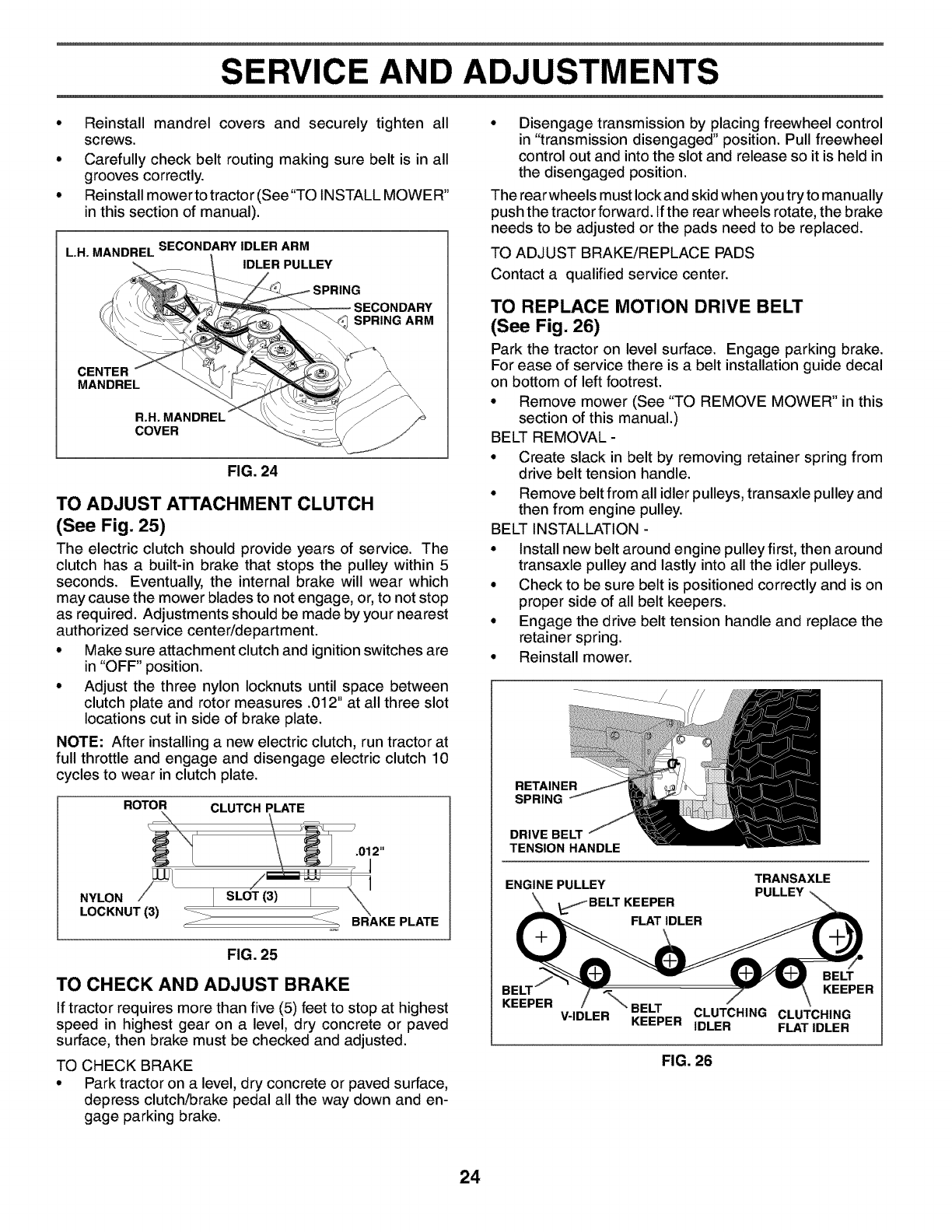
TO REPLACE MOWER BLADE (SECONDARY)
DRIVE BELT (See Fig. 24)
Park the tractor on level surface. Engage parking brake.
• Remove mower (See "TO REMOVE MOWER" in this
section of manual).
• Remove screws from R.H. and L.H. mandrel covers
and remove covers.
REMOVE MOWER DRIVE BELT
(Refer to "TO REMOVE MOWER DRIVE BELT" illustration
in this section of manual).
• Carefully roll belt over the top of R.H. mandrel pulley.
• Remove belt from idler pulleys.
• Check primary idler arm and two idlers to see that they
rotate freely.
• Be sure spring is securely hooked to primary idler arm
and spring arm.
REMOVE MOWER BLADE (SECONDARY) DRIVE BELT
• Carefully roll belt off L.H. mandrel pulley.
• Remove belt from center mandrel pulley, idler pulley,
and R.H. mandrel pulley.
• Remove any dirt or grass which may have accumulated
around mandrels and entire upper deck surface.
• Check secondary idler arm and idler pulley to see that
they rotate freely.
• Be sure spring is hooked in secondary idler arm and
secondary spring arm.
INSTALL NEW MOWER BLADE (SECONDARY) DRIVE
BELT
• Install new belt in lower groove of R.H. mandrel pulley,
idler pulley, and center mandrel pulley as shown.
• Carefully roll belt over L.H. mandrel pulley. Make sure
belt is in all grooves properly.
REINSTALL MOWER DRIVE BELT
(Refer to "TO REMOVE MOWER DRIVE BELT" illustration
in this section of manual).
• Install belt into upper groove of R.H. mandrel pulley
and around both idlers. Pull belt to front of mower to
remove slack.
23
SERVICE AND ADJUSTMENTS
t
• Reinstall mandrel covers and securely tighten all
screws.
• Carefully check belt routing making sure belt is in all
grooves correctly.
• Reinstall mower to tractor (See"TO INSTALL MOWER"
in this section of manual).
L.H. MANDREL SECONDARY IDLER ARM
IDLER PULLEY
SPRING ARM
CENTER
MANDREL
R.H. MANDREL"
COVER
FIG. 24
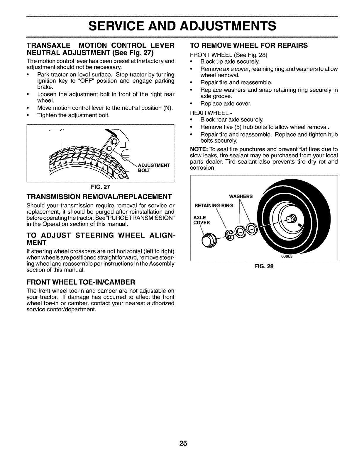
TO ADJUST ATTACHMENT CLUTCH
(See Fig. 25)
The electric clutch should provide years of service. The
clutch has a built-in brake that stops the pulley within 5
seconds. Eventually, the internal brake will wear which
may cause the mower blades to not engage, or, to not stop
as required. Adjustments should be made by your nearest
authorized service center/department.
• Make sure attachment clutch and ignition switches are
in "OFF" position.
• Adjust the three nylon Iocknuts until space between
clutch plate and rotor measures .012" at all three slot
locations cut in side of brake plate.
NOTE: After installing a new electric clutch, run tractor at
full throttle and engage and disengage electric clutch 10
cycles to wear in clutch plate.
ROTOR CLUTCH PLATE
NYLON ISLOT(3) Ij "\
LOCKNUT (3) _ _ BRAKE PLATE
FIG. 25
TO CHECK AND ADJUST BRAKE
If tractor requires more than five (5) feet to stop at highest
speed in highest gear on a level, dry concrete or paved
surface, then brake must be checked and adjusted.
TO CHECK BRAKE
• Park tractor on a level, dry concrete or paved surface,
depress clutch/brake pedal all the way down and en-
gage parking brake.
Disengage transmission by placing freewheel control
in "transmission disengaged" position. Pull freewheel
control out and into the slot and release so it is held in
the disengaged position.
The rear wheels must lock and skid when you try to manually
push the tractor forward. If the rear wheels rotate, the brake
needs to be adjusted or the pads need to be replaced.
TO ADJUST BRAKE/REPLACE PADS
Contact a qualified service center.
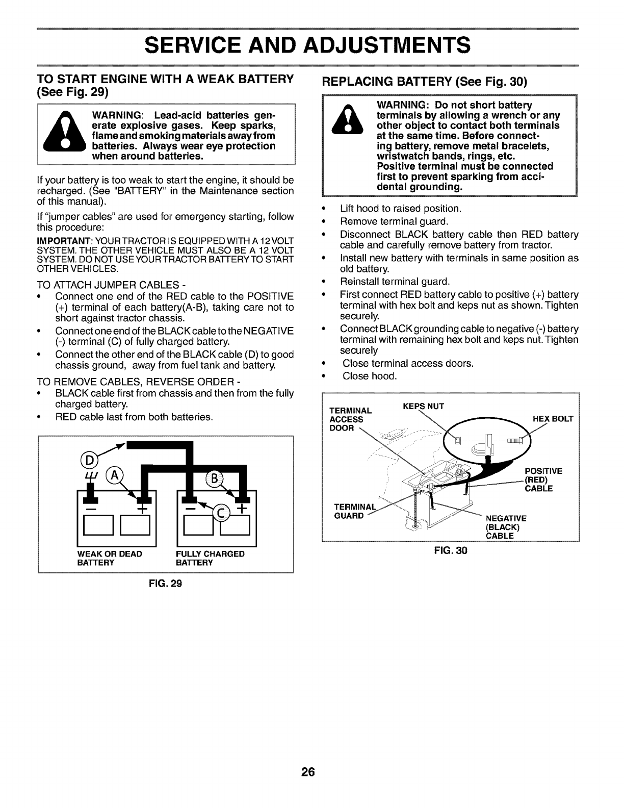
TO REPLACE MOTION DRIVE BELT
(See Fig. 26)
Park the tractor on level surface. Engage parking brake.
For ease of service there is a belt installation guide decal
on bottom of left footrest.
• Remove mower (See "TO REMOVE MOWER" in this
section of this manual.)
BELT REMOVAL-
• Create slack in belt by removing retainer spring from
drive belt tension handle.
• Remove belt from all idler pulleys, transaxle pulley and
then from engine pulley.
BELT INSTALLATION -
• Install new belt around engine pulley first, then around
transaxle pulley and lastly into all the idler pulleys.
• Check to be sure belt is positioned correctly and is on
proper side of all belt keepers.
• Engage the drive belt tension handle and replace the
retainer spring.
• Reinstall mower.
RETAINER
SPRING
DRIVE BELT
TENSION HANDLE
ENGINE PULLEY TRANSAXLE
PULLEY
_BELTKEEPER
FLATIDLER
BE
KEEPER "_" BELT
V-IDLER KEEPER
BELT
KEEPER
CLUTCHING CLUTCHING
IDLER FLAT IDLER
FIG. 26
24
SERVICE AND ADJUSTMENTS
TRANSAXLE MOTION CONTROL LEVER
NEUTRAL ADJUSTMENT (See Fig. 27)
The motion control lever has been preset at the factory and
adjustment should not be necessary.
° Park tractor on level surface. Stop tractor by turning
ignition key to "OFF" position and engage parking
brake.
° Loosen the adjustment bolt in front of the right rear
wheel.
° Move motion control lever to the neutral position (N).
° Tighten the adjustment bolt.
BOLT
TO REMOVE WHEEL FOR REPAIRS
FRONT WHEEL (See Fig. 28)
• Block up axle securely.
° Remove axle cover, retaining ring and washers to allow
wheel removal.
° Repair tire and reassemble.
° Replace washers and snap retaining ring securely in
axle groove.
° Replace axle cover.
REAR WHEEL -
° Block rear axle securely.
° Remove five (5) hub bolts to allow wheel removal.
° Repair tire and reassemble. Replace and tighten hub
bolts securely.
NOTE: To seal tire punctures and prevent flat tires due to
slow leaks, tire sealant may be purchased from your local
parts dealer. Tire sealant also prevents tire dry rot and
corrosion.
FIG. 27
TRANSMISSION REMOVAL/REPLACEMENT
Should your transmission require removal for service or
replacement, it should be purged after reinstallation and
before operating the tractor. See"PU RGETRANSMISSION"
in the Operation section of this manual.
TO ADJUST STEERING WHEEL ALIGN-
MENT
If steering wheel crossbars are not horizontal (left to right)
when wheels are positioned straightforward, remove steer-
ing wheel and reassemble per instructions in the Assembly
section of this manual.
FRONT WHEEL TOE-IN/CAMBER
The front wheel toe-in and camber are not adjustable on
your tractor. If damage has occurred to affect the front
wheel toe-in or camber, contact your nearest authorized
service center/department.
WASHERS
RETAINING RING
AXLE
COVER
00663
FIG. 28
25
SERVICE AND ADJUSTMENTS
TO START ENGINE WITH A WEAK BATTERY
(See Fig. 29)
_WARNING: Lead-acid batteries gen-
erate explosive gases. Keep sparks,
flame and smoking materials away from
batteries. Always wear eye protection
when around batteries.
If your battery is too weak to start the engine, it should be
recharged. (See "BATTERY" in the Maintenance section
of this manual).
If "jumper cables" are used for emergency starting, follow
this procedure:
IMPORTANT: YOURTRACTOR IS EQUIPPEDWlTH A 12VOLT
SYSTEM. THE OTHER VEHICLE MUST ALSO BE A 12 VOLT
SYSTEM. DO NOT USEYOUR TRACTOR BATTERYTO START
OTHER VEHICLES.
TO ATTACH JUMPER CABLES -
• Connect one end of the RED cable to the POSITIVE
(+) terminal of each battery(A-B), taking care not to
short against tractor chassis.
• Connect one end ofthe BLACK cable to the NEGATIVE
(-) terminal (C) of fully charged battery.
• Connect the other end of the BLACK cable (D) to good
chassis ground, away from fuel tank and battery.
TO REMOVE CABLES, REVERSE ORDER -
• BLACK cable first from chassis and then from the fully
charged battery.
• RED cable last from both batteries.
DD
WEAK OR DEAD
BATTERY FULLY CHARGED
BATTERY
FIG. 29
REPLACING BATTERY (See Fig. 30)
WARNING: Do not short battery
terminals by allowing a wrench or any
other object to contact both terminals
at the same time. Before connect-
ing battery, remove metal bracelets,
wristwatch bands, rings, etc.
Positive terminal must be connected
first to prevent sparking from acci-
dental grounding.
° Lift hood to raised position.
° Remove terminal guard.
° Disconnect BLACK battery cable then RED battery
cable and carefully remove battery from tractor.
° Install new battery with terminals in same position as
old battery.
° Reinstall terminal guard.
° First connect RED battery cable to positive (+) battery
terminal with hex bolt and keps nut as shown. Tighten
securely.
° Connect BLACKgrounding cable to negative (-) battery
terminal with remaining hex bolt and keps nut. Tighten
securely
° Close terminal access doors.
° Close hood.
TERMINAL
ACCESS
DOOR _,,,_
KEPS NUT
HEX BOLT
POSITIVE
CABLE
TERMINAL
GUARD
FIG. 30
NEGATIVE
(BLACK)
CABLE
26
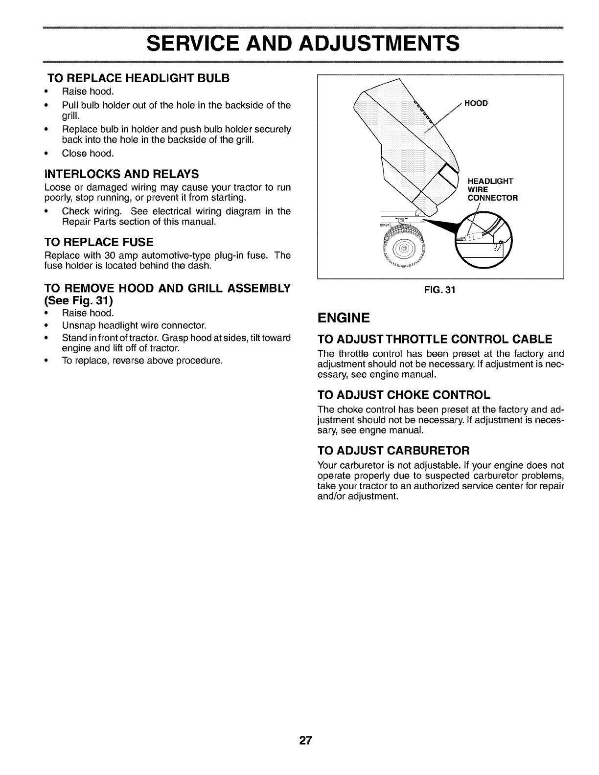
SERVICE AND ADJUSTMENTS
TO REPLACE HEADLIGHT BULB
•Raise hood.
• Pull bulb holder out of the hole in the backside of the
grill.
• Replace bulb in holder and push bulb holder securely
back into the hole in the backside of the grill.
• Close hood.
INTERLOCKS AND RELAYS
Loose or damaged wiring may cause your tractor to run
poorly, stop running, or prevent it from starting.
• Check wiring. See electrical wiring diagram in the
Repair Parts section of this manual.
TO REPLACE FUSE
Replace with 30 amp automotive-type plug-in fuse. The
fuse holder is located behind the dash.
TO REMOVE HOOD AND GRILL ASSEMBLY
(See Fig. 31)
• Raise hood.
• Unsnap headlight wire connector.
• Stand in front of tractor. Grasp hood at sides, tilt toward
engine and lift off of tractor.
• To replace, reverse above procedure.
HOOD
HEADLIGHT
WIRE
CONNECTOR
FIG. 31
ENGINE
TO ADJUST THROTTLE CONTROL CABLE
The throttle control has been preset at the factory and
adjustment should not be necessary. If adjustment is nec-
essary, see engine manual.
TO ADJUST CHOKE CONTROL
The choke control has been preset at the factory and ad-
justment should not be necessary. If adjustment is neces-
sary, see engne manual.
TO ADJUST CARBURETOR
Your carburetor is not adjustable. If your engine does not
operate properly due to suspected carburetor problems,
take your tractor to an authorized service center for repair
and/or adjustment.
27
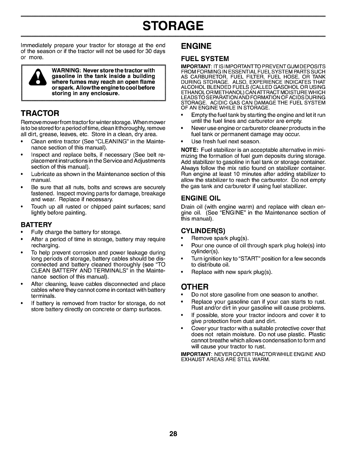
STORAGE
Immediately prepare your tractor for storage at the end
of the season or if the tractor will not be used for 30 days
or more.
WARNING: Never store the tractor with
gasoline in the tank inside a building
where fumes may reach an open flame
or spark. AIIowthe engine to cool before
storing in any enclosure.
TRACTOR
Remove mower from tractor for winter storage. When mower
is to be stored for a period of time, clean it thoroughly, remove
all dirt, grease, leaves, etc. Store in a clean, dry area.
° Clean entire tractor (See "CLEANING" in the Mainte-
nance section of this manual).
° Inspect and replace belts, if necessary (See belt re-
placement instructions in the Service and Adjustments
section of this manual).
° Lubricate as shown in the Maintenance section of this
manual.
° Be sure that all nuts, bolts and screws are securely
fastened. Inspect moving parts for damage, breakage
and wear. Replace if necessary.
° Touch up all rusted or chipped paint surfaces; sand
lightly before painting.
BATTERY
• Fully charge the battery for storage.
• After a period of time in storage, battery may require
recharging.
° To help prevent corrosion and power leakage during
long periods of storage, battery cables should be dis-
connected and battery cleaned thoroughly (see "TO
CLEAN BATTERY AND TERMINALS" in the Mainte-
nance section of this manual).
° After cleaning, leave cables disconnected and place
cables where they cannot come in contact with battery
terminals.
° If battery is removed from tractor for storage, do not
store battery directly on concrete or damp surfaces.
ENGINE
FUEL SYSTEM
IMPORTANT: IT IS IMPORTANTTO PREVENTGUM DEPOSITS
FROM FORMING IN ESSENTIAL FUEL SYSTEM PARTS SUCH
AS CARBURETOR, FUEL FILTER, FUEL HOSE, OR TANK
DURING STORAGE. ALSO, EXPERIENCE INDICATES THAT
ALCOHOL BLENDED FUELS (CALLED GASOHOL OR USING
ETHANOL OR METHANOL) CAN ATTRACT MOISTUREWHICH
LEADSTO SEPARATION AND FORMATION OF ACI DS DURING
STORAGE. ACIDIC GAS CAN DAMAGE THE FUEL SYSTEM
OF AN ENGINE WHILE IN STORAGE.
° Empty the fuel tank by starting the engine and let it run
until the fuel lines and carburetor are empty.
° Never use engine or carburetor cleaner products in the
fuel tank or permanent damage may occur.
° Use fresh fuel next season.
NOTE: Fuel stabilizer is an acceptable alternative in mini-
mizing the formation of fuel gum deposits during storage.
Add stabilizer to gasoline in fuel tank or storage container.
Always follow the mix ratio found on stabilizer container.
Run engine at least 10 minutes after adding stabilizer to
allow the stabilizer to reach the carburetor. Do not empty
the gas tank and carburetor if using fuel stabilizer.
ENGINE OIL
Drain oil (with engine warm) and replace with clean en-
gine oil. (See "ENGINE" in the Maintenance section of
this manual).
CYLINDER(S)
• Remove spark plug(s).
° Pour one ounce of oil through spark plug hole(s) into
cylinder(s).
° Turn ignition key to "START" position for a few seconds
to distribute oil.
° Replace with new spark plug(s).
OTHER
• Do not store gasoline from one season to another.
• Replace your gasoline can if your can starts to rust.
Rust and/or dirt in your gasoline will cause problems.
• If possible, store your tractor indoors and cover it to
give protection from dust and dirt.
• Cover your tractor with a suitable protective cover that
does not retain moisture. Do not use plastic. Plastic
cannot breathe which allows condensation to form and
will cause your tractor to rust.
IMPORTANT: NEVERCOVERTRACTORWHILE ENGINE AND
EXHAUST AREAS ARE STILL WARM.
28

TROUBLESHOOTING POINTS
PROBLEM CAUSE CORRECTION
Will not start
Hard to start
Engine will not turn over
Engine clicks but will not
start
Loss of power
Excessive vibration
1. Out of fuel.
2. Engine not "CHOKED" properly.
3. Engine flooded.
4. Bad spark plug.
5. Dirty air filter.
6. Dirty fuel filter.
7. Water in fuel.
8. Loose or damaged wiring.
9. Carburetor out of adjustment.
10. Engine valves out of adjustment.
11. Extreme cold conditions.
1. Dirty air filter.
2. Bad spark plug.
3. Weak or dead battery.
4. Dirty fuel filter.
5. Stale or dirty fuel.
6. Loose or damaged wiring.
7. Carburetor out of adjustment.
8. Engine valves out of adjustment.
1. Brake pedal not depressed.
2. Attachment clutch is engaged.
3. Weak or dead battery.
4. Blown fuse.
5. Corroded battery terminals.
6. Loose or damaged wiring.
7. Faulty ignition switch.
8. Faulty solenoid or starter.
9. Faulty operator presence switch(es).
1. Weak or dead battery.
2. Corroded battery terminals.
3. Loose or damaged wiring.
4. Faulty solenoid or starter.
1. Cutting too much grass/too fast.
2. Throttle in "CHOKE" position.
3. Build-up of grass, leaves and trash under mower.
4. Dirty air filter.
5. Low oil level/dirty oil.
6. Faulty spark plug.
7. Dirty fuel filter.
8. Stale or dirty fuel.
9. Water in fuel.
10. Spark plug wire loose.
11. Dirty engine air screen/fins.
12. Dirty/clogged muffler.
13. Loose or damaged wiring.
14. Carburetor out of adjustment.
15. Engine valves out of adjustment.
1. Worn, bent or loose blade.
2. Bent blade mandrel.
3. Loose/damaged part(s).
1. Fill fuel tank.
2. See 'qo START ENGINE" in Operation section.
3. Wait several minutes before attempting to start.
4. Replace spark plug.
5. Clean/replace air filter.
6. Replace fuel filter.
7. Empty fuel tank and carburetor, refill tank with fresh
gasoline and replace fuel filter.
8. Check all wiring.
9. See 'qo Adjust Carburetor" in Service Adjustments
section.
10. Contact an authorized service center/department.
11. See "To start engine" in operation section
1. Clean/replace air filter.
2. Replace spark plug.
3. Recharge or replace battery.
4. Replace fuel filter.
5. Empty fuel tank and refill tank with fresh, clean gasoline.
6. Check all wiring.
7. See 'qo Adjust Carburetor" in Service Adjustments
section.
8. Contact an authorized service center/department.
1. Depress brake pedal.
2. Disengage attachment clutch.
3. Recharge or replace battery.
4. Replace fuse.
5. Clean battery terminals.
6. Check all wiring.
7. Check/replace ignition switch.
8. Check/replace solenoid or starter.
9. Contact an authorized service center/department.
1. Recharge or replace battery.
2. Clean battery terminals.
3. Check all wiring.
4. Check/replace solenoid or starter.
1. Raise cutting height/reduce speed.
2. Adjust throttle control.
3. Clean underside of mower housing.
4. Clean/replace air filter.
5. Check oil level/change oil.
6. Clean and regap or change spark plug.
7. Replace fuel filter.
8. Empty fuel tank and refill tank with fresh, clean gasoline.
9. Empty fuel tank and carburetor, refill tank with fresh
gasoline and replace fuel filter.
10. Connect and tighten spark plug wire.
11. Clean engine air screen/fins.
12. Clean/replace muffler.
13. Check atlwiring.
14. See 'qo Adjust Carburetor" in Service Adjustments
section.
15. Contact an authorized service center/department.
1. Replace blade. Tighten blade bolt.
2. Replace blade mandrel.
3. Tighten loose part(s). Replace damaged parts.
29

TROUBLESHOOTING POINTS
PROBLEM CAUSE CORRECTION
1. Faulty operator-safety presence control system.Engine continues to run
when operator leaves seat
with attachment clutch
engaged
Poorcut-uneven
Mower blades will not
rotate
Poor grass discharge
Headlight(s) not working
(if so equipped)
Battery will not charge
Loss of drive
Engine "backfires" when
turning engine "OFF"
1. Worn, bent or loose blade.
2. Mower deck not level.
3. Buildup of grass, leaves, and trash under mower.
4. Bent blade mandrel.
5. Clogged mower deck vent holes from buildup of
grass, leaves, and trash around mandrels.
1. Obstruction in clutch mechanism.
2. Worn/damaged mower drive belt.
3. Frozen idler pulley.
4. Frozen blade mandrel.
1. Engine speed too slow.
2. Travel speed too fast.
3. Wet grass.
4. Mower deck not level.
5. Low/uneven tire air pressure.
6. Worn, bent or loose blade.
7. Buildup of grass, leaves and trash under mower.
8. Mower drive belt worn.
9. Blades improperly installed.
10. Improper blades used.
11. Clogged mower deck vent holes from buildup of
grass, leaves, and trash around mandrels.
1. Switch is "OFF".
2. Bulb(s) or tamp(s) burned out.
3. Faulty light switch.
4. Loose or damaged wiring.
5. Blown fuse.
1. Bad batterycetl(s).
2. Poor cable connections.
3. Faulty regulator (if so equipped).
4. Faulty alternator.
1. Freewheel control in "disengaged" position.
2. Motion drive belt worn, damaged, or broken.
3. Air trapped in transmission during shipment
or servicing.
1. Engine throttle control not set between hatf and
full speed (fast) position before stopping engine.
1. Check wiring, switches and connections. If not
corrected, contact an authorized service center/
department.
1. Replace blade. Tighten blade bolt.
2. Level mower deck.
3. Clean underside of mower housing.
4. Replace blade mandrel.
5. Clean around mandrels to open vent holes.
1. Remove obstruction.
2. Replace mower drive belt.
3. Replace idler pulley.
4. Replace blade mandrel.
1. Place throttle control in "FAST" position.
2. Shift to slower speed.
3. Allow grass to dry before mowing.
4. Level mower deck.
5. Check tires for proper air pressure.
6. Replace/sharpen blade. Tighten blade bolt.
7. Clean underside of mower housing.
8. Replace mower drive belt.
9. Reinstall blades sharp edge down.
10. Replace with blades listed in this manual.
11. Clean around mandrels to open vent holes.
1. Turn switch "ON".
2. Replace bulb(s) or tamp(s).
3. Check/replace light switch.
4. Check wiring and connections.
5. Replace fuse.
1. Replace battery.
2. Check/clean atl connections.
3. Replace regulator.
4. Replace alternator.
1. Place freewheel control in "engaged" position.
2. Replace motion drive belt.
3. Purge transmission.
Move throttle control between hatf and full speed
(fast) position before stopping engine.
30
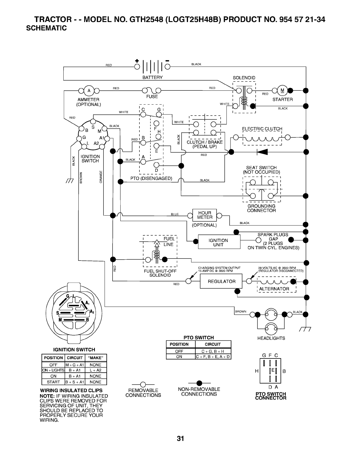
TRACTOR - - MODEL NO. GTH2548 (LOGT25H48B) PRODUCT NO. 954 57 21-34
SCHEMATIC
BATTERY
RED FUSE
AMMETER
(OPTIONAL)
WHtTE
IGNITION
SWITCH
O
BLACK
I I
,AC G'
i
, H
I _1
CLUTCH /BRAKE
(PEDAL UP)
SOLENOID
RED I
, [_J_ , STARTER
WHITE..._ _ _ •
I _J III _ B_CK •
I _
---- -q-
ELECTRIC CLUTCH
I
RED
D
PTO (DISENGAGED)
BLUE
_- . FUEL I
LINE I
I
I
LI
FUEL SHUT-OFF
SOLENOID
BLACK
CI HOUR [_
METER _J_
I (OITIONAL i I
IGNITION
!.[ UNIT
SEAT SWITCH
(NOT OCCUPIED)
I 1
I I
I I
q F-
I I
I
I
GROUNDING
CONNECTOR
BLACK
A •
lr SPARK PLUGS •
GAP
I_(2 PLUGS v •
I ON TWIN CYL. ENGINES)
I
CHARGING SYSTEM OUTPUT 28 VOLTS AC @ 3600 RPM
IGNITION SWITCH
POSITION CIRCUIT "MAKE"
OFF M + G + A1 NONE
ON+LIGHTS B+A1 L+A2
ON B + A1 NONE
START B + S + A1 NONE
WIRING INSULATED CLIPS
NOTE: IF WIRING INSULATED
CLIPS WERE REMOVED FOR
SERVICING OF UNIT, THEY
SHOULD BE REPLACED TO
PROPERLY SECURE YOUR
WIRING.
O
REMOVABLE
CONNECTIONS
15 AMP DC @ 3600 RPM (REGULATOR DISCONNECTED)
RED _ REGULATOR _l .......... )
eqD
PTO SWITCH HEADLIGHTS
POSITION CIRCUIT
OFF C+G,B+H
ON C+F,B+E,A+D
NON-REMOVABLE
CONNECTIONS
GFC
DA
PTO SWITCH
CONNECTOR
31
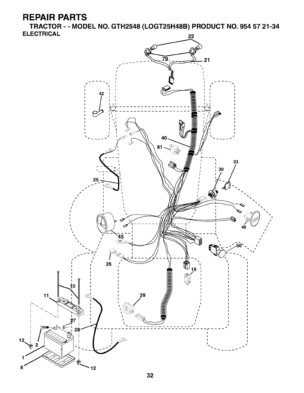
REPAIR PARTS
TRACTOR --MODEL NO. GTH2548 (LOGT25H48B) PRODUCT NO. 954 57 21-34
ELECTRICAL 22
f/f_
I
I
I
I
I
III
Iiii
I
-I
I
81
16
33
30
I
I
I
32
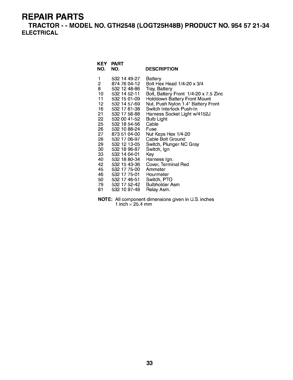
REPAIR PARTS
TRACTOR --MODEL NO. GTH2548 (LOGT25H48B) PRODUCT NO. 954 57 21-34
ELECTRICAL
KEY PART
NO. NO. DESCRIPTION
1 532 14 49-27 Battery
2 874 76 04-12 Bolt Hex Head 1/4-20 x 3/4
8 532 12 48-86 Tray, Battery
10 532 14 52-11 Bolt, Battery Front 1/4-20 x 7.5 Zinc
11 532 15 01-09 Holddown Battery Front Mount
12 532 14 57-69 Nut, Push Nylon 1.4" Battery Front
16 532 17 61-38 Switch Interlock Push-In
21 532 17 56-88 Harness Socket Light w/4152J
22 532 00 41-52 Bulb Light
25 532 18 54-56 Cable
26 532 10 88-24 Fuse
27 873 51 04-00 Nut Keps Hex 1/4-20
28 532 17 06-97 Cable Bolt Ground
29 532 12 13-05 Switch, Plunger NC Gray
30 532 18 96-87 Switch, Ign
33 532 14 04-01 Key
40 532 18 80-34 Harness Ign.
42 532 15 43-36 Cover, Terminal Red
45 532 17 75-00 Ammeter
46 532 17 75-01 Hourmeter
50 532 17 46-51 Switch, PTO
79 532 17 52-42 Bulbholder Asm
81 532 10 97-48 Relay Asm.
NOTE: All component dimensions given in U.S. inches
1 inch = 25.4 mm
33
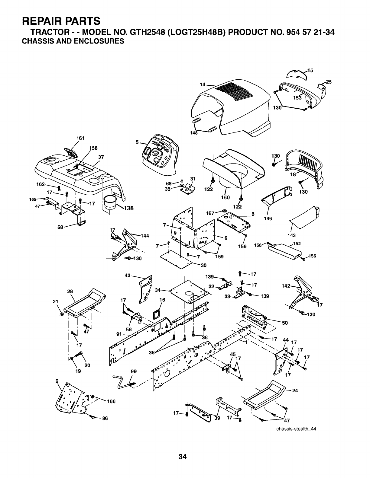
REPAIR PARTS
TRACTOR - - MODEL NO. GTH2548 (LOGT25H48B) PRODUCT NO. 954 57 21-34
CHASSIS AND ENCLOSURES
161
i
17
_o
19
2
17
56
99
16
4517
34
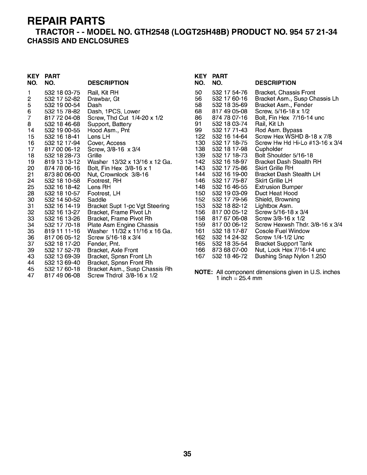
REPAIR PARTS
TRACTOR --MODEL NO. GTH2548 (LOGT25H48B) PRODUCT NO. 954 57 21-34
CHASSIS AND ENCLOSURES
KEY PART KEY PART
NO. NO. DESCRIPTION NO. NO. DESCRIPTION
1 532 18 03-75 Rail, Kit RH 50 532 17 54-76
2 532 17 52-82 Drawbar, Gt 56 532 17 60-16
5 532 19 00-54 Dash 58 532 18 35-69
6 532 15 78-82 Dash, 1PCS, Lower 68 817 49 05-08
7 817 72 04-08 Screw, Thd Cut 1/4-20 x 1/2 86 874 78 07-16
8 532 18 46-68 Support, Battery 91 532 18 03-74
14 532 19 00-55 Hood Asm., Pnt 99 532 17 71-43
15 532 16 18-41 Lens LH 122 532 16 14-64
16 532 12 17-94 Cover, Access 130 532 17 18-75
17 817 00 06-12 Screw, 3/8-16 x 3/4 138 532 18 17-98
18 532 18 28-73 Grille 139 532 17 18-73
19 8191313-12 Washer 13/32x13/16x12Ga. 142 5321618-97
20 874 78 06-16 Bolt, Fin Hex 3/8-16 x 1 143 532 17 75-86
21 873 80 06-00 Nut, Crownlock 3/8-16 144 532 16 19-00
24 532 18 10-58 Footrest, RH 146 532 17 75-87
25 532 16 18-42 Lens RH 148 532 16 46-55
28 532 18 10-57 Footrest, LH 150 532 19 03-09
30 532 14 50-52 Saddle 152 532 17 79-56
31 532 16 14-19 Bracket Supt 1-pcVgt Steering 153 532 18 82-12
32 532 16 13-27 Bracket, Frame Pivot Lh 156 817 00 05-12
33 532 16 13-26 Bracket, Frame Pivot Rh 158 817 67 06-08
34 532 17 70-18 Plate Asm Engine Chassis 159 817 00 06-12
35 81911 11-16 Washer 11/32x11/16x16Ga. 161 5321817-87
36 8170605-12 Screw 5/16-18 x 3/4 162 532 1424-32
37 532 18 17-20 Fender, Pnt. 165 532 18 35-54
39 532 17 52-78 Bracket, Axle Front 166 873 68 07-00
43 532 13 69-39 Bracket, Spnsn Front Lh 167 532 18 46-72
44 532 13 69-40 Bracket, Spnsn Front Rh
45 532 17 60-18 Bracket Asm., Susp Chassis Rh
47 817 49 06-08 Screw Thdrol 3/8-16 x 1/2
Bracket, Chassis Front
Bracket Asm., Susp Chassis Lh
Bracket Asm., Fender
Screw, 5/16-18 x 1/2
Bolt, Fin Hex 7/16-14 unc
Rail, Kit Lh
Rod Asm. Bypass
Screw HexWSHD 8-18 x 7/8
Screw Hw Hd Hi-Lo #13-16 x 3/4
Cupholder
Bolt Shoulder 5/16-18
Bracket Dash Stealth RH
Skirt Grille RH
Bracket Dash Stealth LH
Skirt Grille LH
Extrusion Bumper
Duct Heat Hood
Shield, Browning
Lightbox Asm.
Screw 5/16-18 x 3/4
Screw 3/8-16 x 1/2
Screw Hexwsh Thdr. 3/8-16 x 3/4
Cosole Fuel Window
Screw 1/4-1/2 Unc
Bracket Support Tank
Nut, Lock Hex 7/16-14 unc
Bushing Snap Nylon 1.250
NOTE: All component dimensions given in U.S. inches
1 inch = 25.4 mm
35
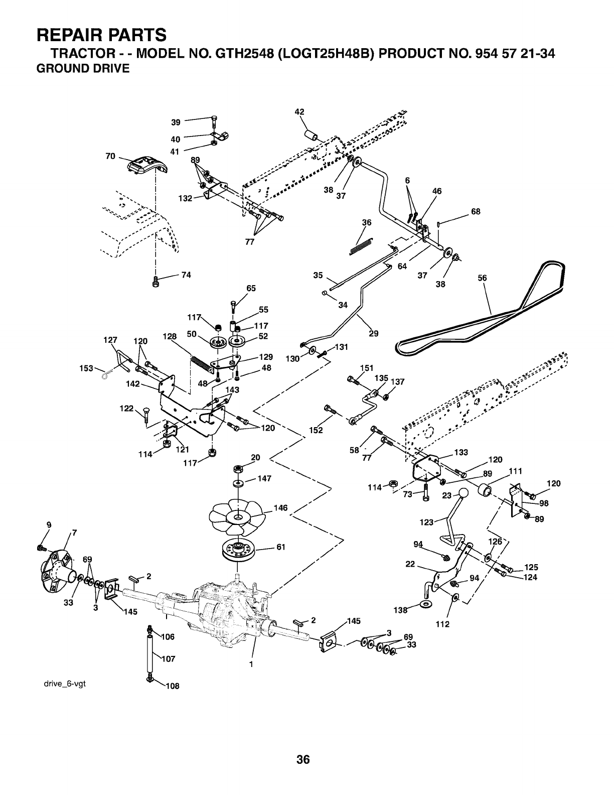
REPAIR PARTS
TRACTOR - - MODEL NO. GTH2548 (LOGT25H48B) PRODUCT NO. 954 57 21-34
GROUND DRIVE
69
33 3
drive_6-vgt
36
64 37
46
68
38 56
\
127 120
122\
128 50_
108
143
48
152
t_147
_146 /
./
./
29
,_ 120
112
36
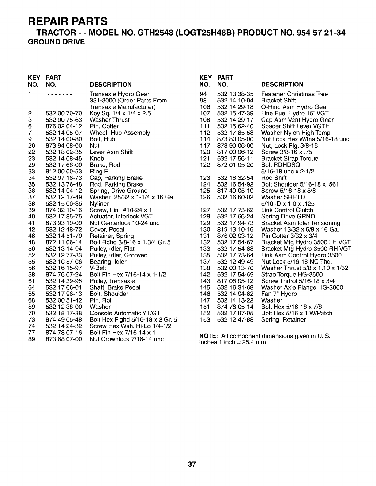
REPAIR PARTS
TRACTOR --MODEL NO. GTH2548 (LOGT25H48B) PRODUCT NO. 954 57 21-34
GROUND DRIVE
KEY PART KEY PART
NO. NO. DESCRIPTION NO. NO.
1 Transaxle Hydro Gear 94 532 13 38-35
331-3000 (Order Parts From 98 532 14 10-04
Transaxle Manufacturer) 106 532 14 29-18
2 5320070-70 KeySq. 1/4x 1/4x2.5 107 532 1547-39
3 532 00 75-63 Washer Thrust 108 532 14 29-17
6 876 02 04-12 Pin, Cotter 111 532 15 62-40
7 532 14 05-07 Wheel, Hub Assembly 112 532 17 85-58
9 532 14 00-80 Bolt, Hub 114 873 80 05-00
20 873 94 08-00 Nut 117 873 90 06-00
22 532 18 02-35 Lever Asm Shift 120 817 00 06-12
23 5321408-45 Knob 121 5321756-11
29 532 17 66-00 Brake, Rod 122 872 01 05-20
33 8120000-53 Ring E
34 532 07 16-73 Cap, Parking Brake 123 532 18 32-54
35 532 13 76-48 Rod, Parking Brake 124 532 16 54-92
36 532 14 94-12 Spring, Drive Ground 125 817 49 05-10
37 532 12 17-49 Washer 25/32 x 1-1/4 x 16 Ga. 126 532 16 60-02
38 532 15 00-35 Nyliner
39 87432 10-16 Screw, Fin. #10-24x 1 127 532 1773-62
40 532 17 85-75 Actuator, Interlock VGT 128 532 17 66-24
41 873 93 10-00 Nut Centerlock 10-24 unc 129 532 17 94-73
42 532 12 48-72 Cover, Pedal 130 819 13 10-16
46 532 14 51-70 Retainer, Spring 131 876 02 03-12
48 872 11 06-14 Bolt Rdhd 3/8-16 x 1.3/4 Gr. 5 132 532 17 54-67
50 532 13 14-94 Pulley, Idler, Flat 133 532 17 54-68
52 532 12 77-83 Pulley, Idler, Grooved 135 532 17 73-64
55 532 10 57-06 Bearing, Idler 137 532 12 49-49
56 532 16 15-97 V-Belt 138 532 00 13-70
58 874 76 07-24 Bolt Fin Hex 7/16-14 x 1-1/2 142 532 17 54-69
61 532 14 39-95 Pulley, Transaxle 143 817 06 05-12
64 532 17 66-01 Shaft, Brake Pedal 145 532 16 31-68
65 532 17 96-13 Bolt, Shoulder 146 532 14 04-62
68 532 00 51-42 Pin, Roll 147 532 14 13-22
69 532 12 38-00 Washer 151 874 76 05-14
70 532 18 17-88 Console Automatic YT/GT 152 532 17 87-05
73 874 49 05-48 Bolt Hex Flghd 5/16-18 x 3 Gr. 5 153 532 12 47-88
74 532 14 24-32 Screw HexWsh. Hi-Lo 1/4-1/2
77 874 78 07-16 Bolt Fin Hex 7/16-14 x 1
89 873 68 07-00 Nut Crownlock 7/16-14 unc
DESCRIPTION
Fastener Christmas Tree
Bracket Shift
O-Ring Asm Hydro Gear
Line Fuel Hydro 15" VGT
Cap Asm Vent Hydro Gear
Spacer Shift Lever VGTH
Washer Nylon High Temp
Nut Lock Hex W/Ins 5/16-18 unc
Nut, Lock Fig. 3/8-16
Screw 3/8-16 x .75
Bracket Strap Torque
Bolt RDHDSQ
5/16-18 unc x 2-1/2
Rod Shift
Bolt Shoulder 5/16-18 x .561
Screw 5/16-18 x 5/8
Washer SRRTD
5/16 ID x 1.0 x.125
Link Control Clutch
Spring Drive GRND
Bracket Asm Idler Tensioning
Washer 13/32 x 5/8 x 16 Ga.
Pin Cotter 3/32 x 3/4
Bracket Mtg Hydro 3500 LH VGT
Bracket Mtg Hydro 3500 RH VGT
Link Asm Control Hydro 3500
Nut Lock 5/16-18 NC Thd.
Washer Thrust 5/8 x 1.10 x 1/32
Strap Torque HG-3500
Screw Thdrol 5/16-18 x 3/4
Washer Axle Flange HG-3000
Fan 7" Hydro
Washer
Bolt Hex 5/16-18 x 7/8
Bolt Hex 5/16 x 1 W/Patch
Spring, Retainer
NOTE: All component dimensions given in U. S.
inches 1 inch = 25.4 mm
37
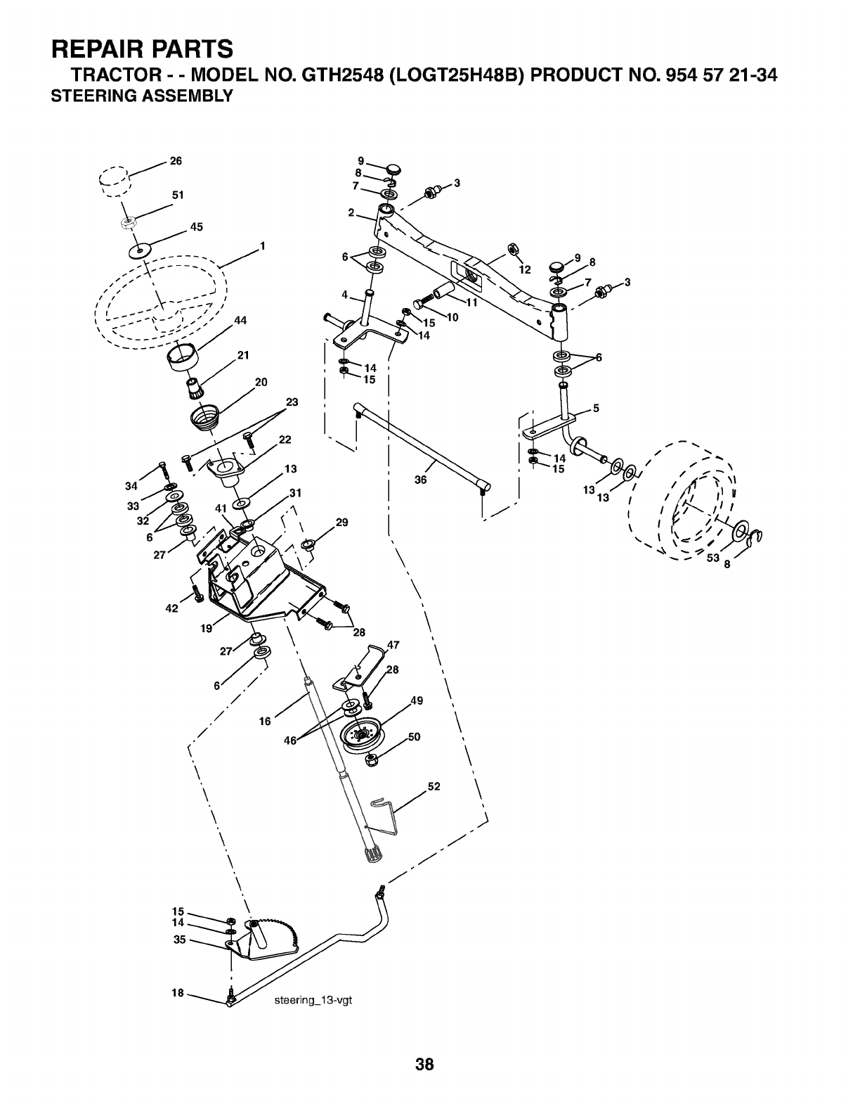
REPAIR PARTS
TRACTOR - - MODEL NO. GTH2548 (LOGT25H48B) PRODUCT NO. 954 57 21-34
STEERING ASSEMBLY
20
23
34
33
32
6
42
6'
/
/"
/
\
\
\
\
\
22
13
/
28
i
I
36
\\\\
\
\
\
\
\
i\
i
s
J
38
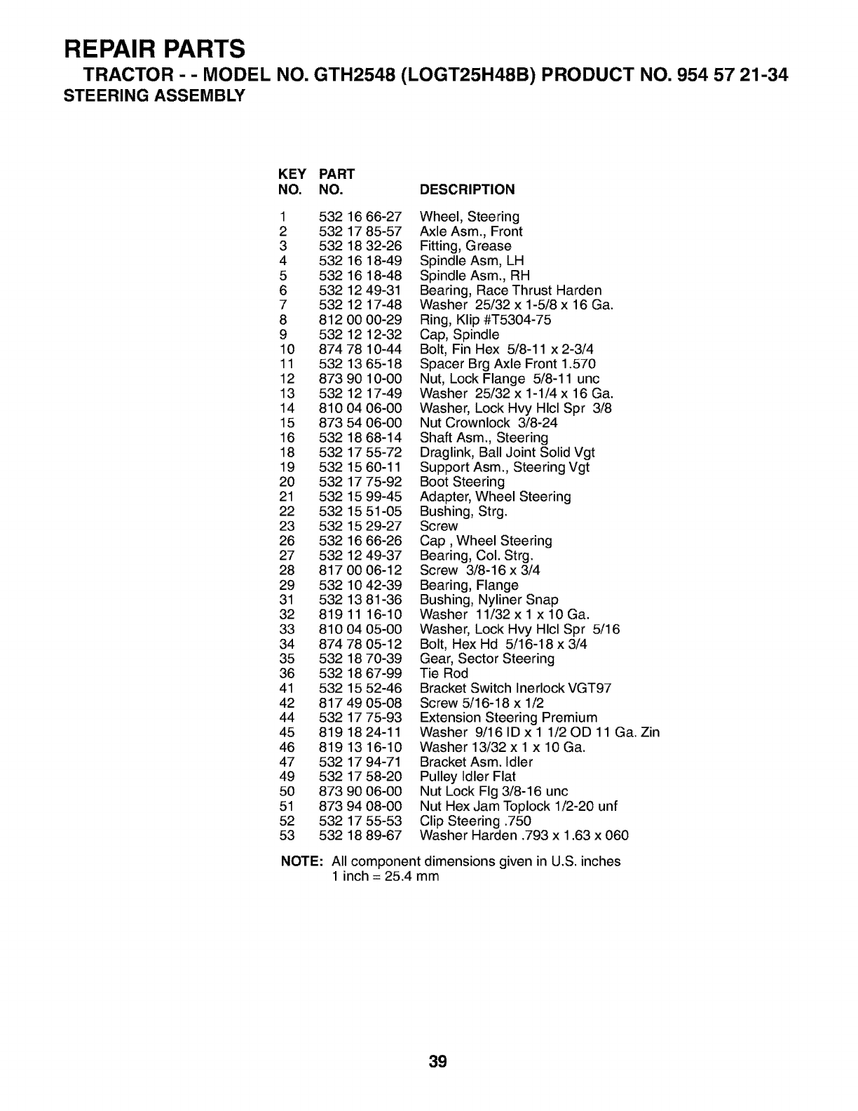
REPAIR PARTS
TRACTOR --MODEL NO. GTH2548 (LOGT25H48B) PRODUCT NO. 954 57 21-34
STEERING ASSEMBLY
KEY PART
NO. NO. DESCRIPTION
1 532 16 66-27
2 532 17 85-57
3 532 18 32-26
4 532 16 18-49
5 532 16 18-48
6 532 12 49-31
7 532 12 17-48
8 812 00 00-29
9 532 12 12-32
10 874 78 10-44
11 532 1365-18
12 873 90 10-00
13 532 12 17-49
14 810 04 06-00
15 873 54 06-00
16 532 18 68-14
18 532 17 55-72
19 532 1560-11
20 532 17 75-92
21 532 15 99-45
22 532 15 51-05
23 532 15 29-27
26 532 16 66-26
27 532 12 49-37
28 817 00 06-12
29 532 10 42-39
31 532 13 81-36
32 819 11 16-10
33 810 04 05-00
34 874 78 05-12
35 532 18 70-39
36 532 18 67-99
41 532 15 52-46
42 817 49 05-08
44 532 17 75-93
45 819 1824-11
46 819 13 16-10
47 532 17 94-71
49 532 17 58-20
50 873 90 06-00
51 873 94 08-00
52 532 17 55-53
53 532 18 89-67
Wheel, Steering
Axle Asm., Front
Fitting, Grease
Spindle Asm, LH
Spindle Asm., RH
Bearing, Race Thrust Harden
Washer 25/32 x 1-5/8 x 16 Ga.
Ring, Klip #T5304-75
Cap, Spindle
Bolt, Fin Hex 5/8-11 x 2-3/4
Spacer Brg Axle Front 1.570
Nut, Lock Flange 5/8-11 unc
Washer 25/32 x 1-1/4 x 16 Ga.
Washer, Lock Hvy Hlcl Spr 3/8
Nut Crownlock 3/8-24
Shaft Asm., Steering
Draglink, Ball Joint Solid Vgt
Support Asm., Steering Vgt
Boot Steering
Adapter, Wheel Steering
Bushing, Strg.
Screw
Cap, Wheel Steering
Bearing, Col. Strg.
Screw 3/8-16 x 3/4
Bearing, Flange
Bushing, Nyliner Snap
Washer 11/32 x 1 x 10 Ga.
Washer, Lock Hvy Hlcl Spr 5/16
Bolt, Hex Hd 5/16-18 x 3/4
Gear, Sector Steering
Tie Rod
Bracket Switch Inerlock VGT97
Screw 5/16-18 x 1/2
Extension Steering Premium
Washer 9/16 ID x 1 1/20D 11 Ga. Zin
Washer 13/32 x 1 x 10 Ga.
Bracket Asm. Idler
Pulley Idler Flat
Nut Lock Fig 3/8-16 unc
Nut Hex Jam Toplock 1/2-20 unf
Clip Steering .750
Washer Harden .793 x 1.63 x 060
NOTE: All component dimensions given in U.S. inches
1 inch = 25.4 mm
39

REPAIR PARTS
TRACTOR - - MODEL NO. GTH2548 (LOGT25H48B) PRODUCT NO. 954 57 21-34
ENGINE
I
_2o
84
I
18
engine-kohler22 17-vgt
11
41
42
4O
85
__2
69
I i
_86 ,
I
2
29
\
SPARK ARRESTER KIT
4O
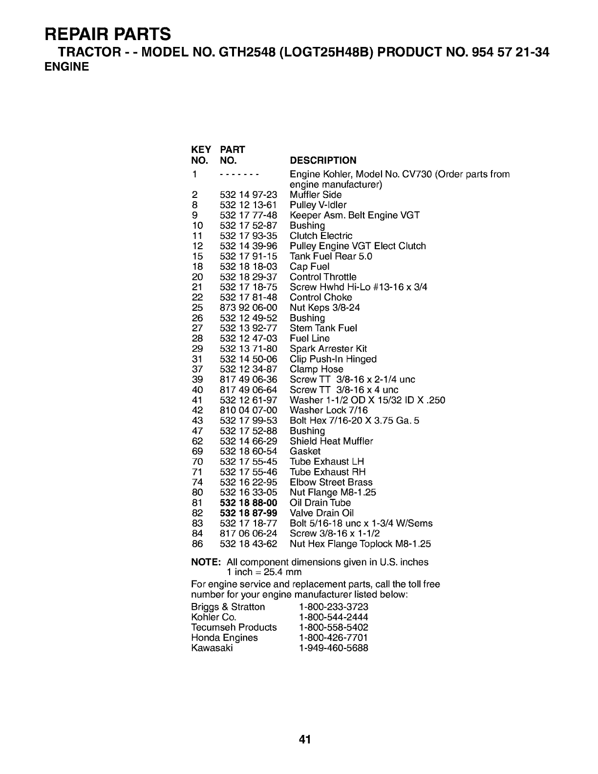
REPAIR PARTS
TRACTOR --MODEL NO. GTH2548 (LOGT25H48B) PRODUCT NO. 954 57 21-34
ENGINE
KEY PART
NO. NO. DESCRIPTION
1 Engine Kohler, Model No. CV730 (Order parts from
engine manufacturer)
2 532 14 97-23 Muffler Side
8 532 12 13-61 Pulley V-Idler
9 532 17 77-48 Keeper Asm. Belt Engine VGT
10 532 17 52-87 Bushing
11 532 17 93-35 Clutch Electric
12 532 14 39-96 Pulley Engine VGT Elect Clutch
15 532 17 91-15 Tank Fuel Rear 5.0
18 532 18 18-03 Cap Fuel
20 532 18 29-37 ControIThrottle
21 532 17 18-75 Screw Hwhd Hi-Lo #13-16 x 3/4
22 532 17 81-48 Control Choke
25 873 92 06-00 Nut Keps 3/8-24
26 532 12 49-52 Bushing
27 532 13 92-77 Stem Tank Fuel
28 532 12 47-03 Fuel Line
29 532 13 71-80 Spark Arrester Kit
31 532 14 50-06 Clip Push-In Hinged
37 532 12 34-87 Clamp Hose
39 8174906-36 ScrewTT 3/8-16x2-1/4unc
40 817 49 06-64 Screw TT 3/8-16 x 4 unc
41 532 12 61-97 Washer 1-1/20D X 15/32 ID X .250
42 810 04 07-00 Washer Lock 7/16
43 532 17 99-53 Bolt Hex 7/16-20 X 3.75 Ga. 5
47 532 17 52-88 Bushing
62 532 14 66-29 Shield Heat Muffler
69 532 18 60-54 Gasket
70 532 17 55-45 Tube Exhaust LH
71 532 17 55-46 Tube Exhaust RH
74 532 16 22-95 Elbow Street Brass
80 532 16 33-05 Nut Flange M8-1.25
81 532 18 88-00 Oil Drain Tube
82 532 18 87-99 Valve Drain Oil
83 532 17 18-77 Bolt 5/16-18 unc x 1-3/4 W/Sems
84 817 06 06-24 Screw 3/8-16 x 1-1/2
86 532 18 43-62 Nut Hex Flange Toplock M8-1.25
NOTE: All component dimensions given in U.S. inches
1 inch = 25.4 mm
For engine service and replacement parts, call the toll free
number for your engine manufacturer listed below:
Briggs & Stratton 1-800-233-3723
Kohler Co. 1-800-544-2444
Tecumseh Products 1-800-558-5402
Honda Engines 1-800-426-7701
Kawasaki 1-949-460-5688
41
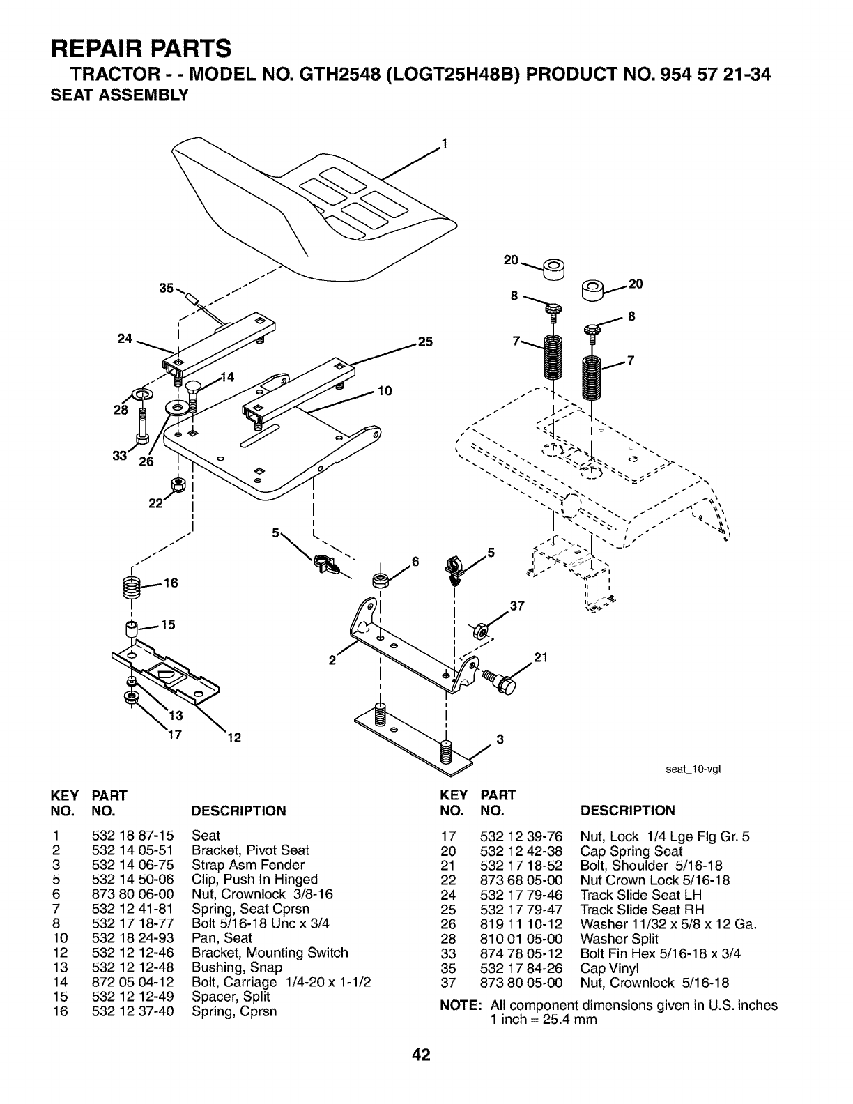
REPAIR PARTS
TRACTOR - - MODEL NO. GTH2548 (LOGT25H48B) PRODUCT NO. 954 57 21-34
SEAT ASSEMBLY
24
28
KEY PART
NO. NO. DESCRIPTION
10
37
I
II I
21
KEY PART
NO. NO.
seatl 0-vgt
DESCRIPTION
1 532 18 87-15
2 532 14 05-51
3 532 14 06-75
5 532 14 50-06
6 873 80 06-00
7 532 12 41-81
8 532 17 18-77
10 532 18 24-93
12 532 12 12-46
13 532 12 12-48
14 872 05 04-12
15 532 12 12-49
16 532 12 37-40
Seat
Bracket, Pivot Seat
Strap Asm Fender
Clip, Push In Hinged
Nut, Crownlock 3/8-16
Spring, Seat Cprsn
Bolt 5/16-18 Unc x 3/4
Pan, Seat
Bracket, Mounting Switch
Bushing, Snap
Bolt, Carriage 1/4-20 x 1-1/2
Spacer, Split
Spring, Cprsn
17 532 12 39-76
20 532 12 42-38
21 532 17 18-52
22 873 68 05-00
24 532 17 79-46
25 532 17 79-47
26 81911 10-12
28 810 01 05-00
33 874 78 05-12
35 532 17 84-26
37 873 80 05-00
Nut, Lock 1/4 Lge Fig Gr. 5
Cap Spring Seat
Bolt, Shoulder 5/16-18
Nut Crown Lock 5/16-18
Track Slide Seat LH
Track Slide Seat RH
Washer 11/32 x 5/8 x 12 Ga.
Washer Split
Bolt Fin Hex 5/16-18 x 3/4
Cap Vinyl
Nut, Crownlock 5/16-18
NOTE: All component dimensions given in U.S. inches
1 inch = 25.4 mm
42

REPAIR PARTS
TRACTOR --MODEL NO. GTH2548 (LOGT25H48B) PRODUCT NO. 954 57 21-34
DECALS 3 7
15 5 5 10
24
I
11 2
KEY PART KEY PART
NO. NO. DESCRIPTION NO. NO. DESCRIPTION
Decal, Deck Caution 13 532 18 96-69
Deck Hvy Duty 14 532 17 52-91
Hood RH 15 532 18 89-25
Hood LH 23 532 10 62-02
Side Panel 24 532 14 50-05
Warning - - 532 16 69-60
Cust. Resp. - - 532 18 19-17
Operator - - 532 18 19-16
Danger - - 532 19 08-44
Foot Rest
1 532 17 85-02
2 532 17 84-82 Decal,
3 532 18 89-47 Decal,
4 532 18 89-48 Decal,
5 532 18 97-08 Decal,
6 532 17 05-63 Decal,
7 532 18 09-41 Decal,
8 532 18 28-54 Decal,
10 532 15 71-40 Decal,
11 532 18 12-53 Decal,
Decal, Replacement
Decal, V-Belt Schematic
Decal, Ins. Strg Whl
Reflector, Taillight LH/RH
Decal, Btry Dngr/Psn
Decal, Drawbar
Pad Footrest RH
Pad Footrest LH
Manual, Operator's (Eng.)
WHEELS & TIRES
2 3
wheel
410
59
8
KEY PART
NO. NO.
1
2
3
4
5
6
7
8
9
10
11
12
DESCRIPTION
532 05 91-92 Cap, Valve, Tire
532 06 51-39 Stem, Valve
532 14 45-09 Rim Assembly, Front
532 00 81-34 Tube, Front (Service Item Only)
532 10 62-30 Tire, Front
532 12 49-57 Fitting, Grease
532 12 49-59 Bearing, Flange (Front Wheel
Only)
532 17 50-39 Cap, Hub
532 10 55-88 Tire, Rear
532 00 71-54 Tube, Rear (Service Item Only)
532 14 45-10 Rim Assembly, Rear
532 12 48-60 Fitting, Grease
532 14 43-34 Sealant, Tire (10 oz. Tube)
NOTE: All component dimensions given in U.S. inches
1 inch = 25.4 mm
43
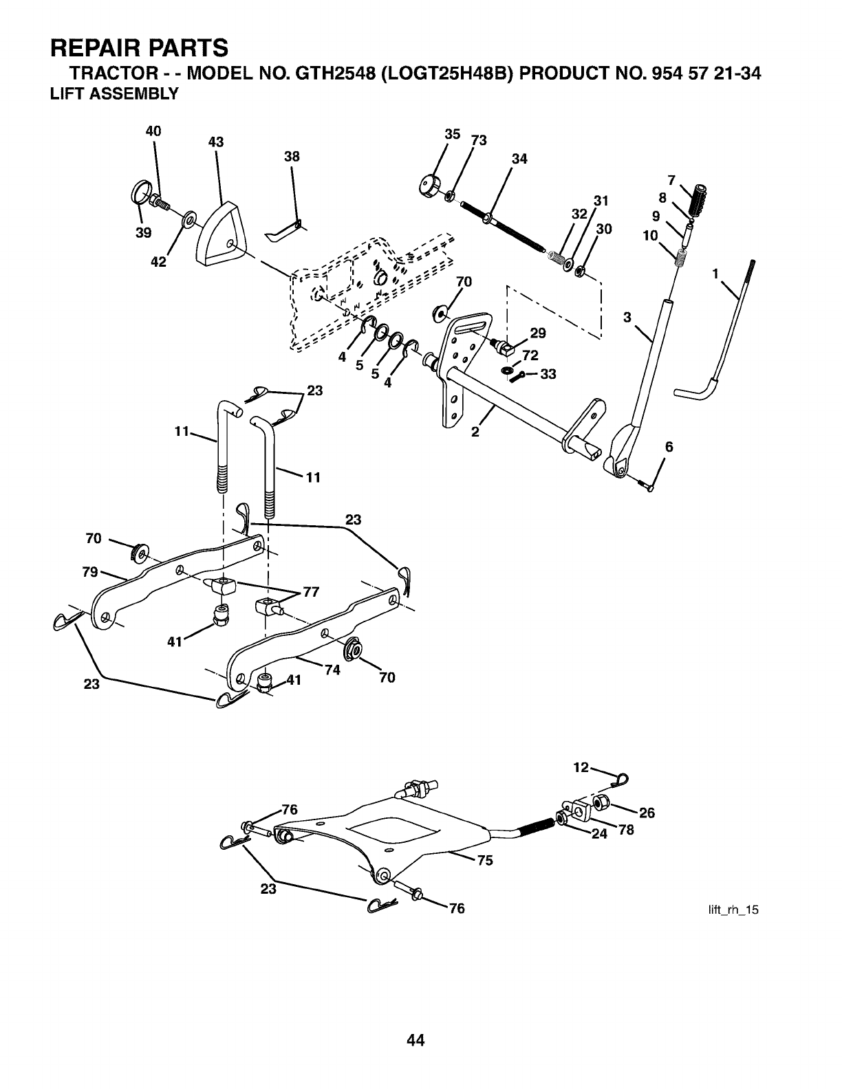
REPAIR PARTS
TRACTOR - - MODEL NO. GTH2548 (LOGT25H48B) PRODUCT NO. 954 57 21-34
LIFT ASSEMBLY
4O
39
42
43 35 73
38 34
4
4
23
70
2
32
i
I\
29 _,
72
7
31 8
3
9
10
6
23 7O
lift rh 15
44
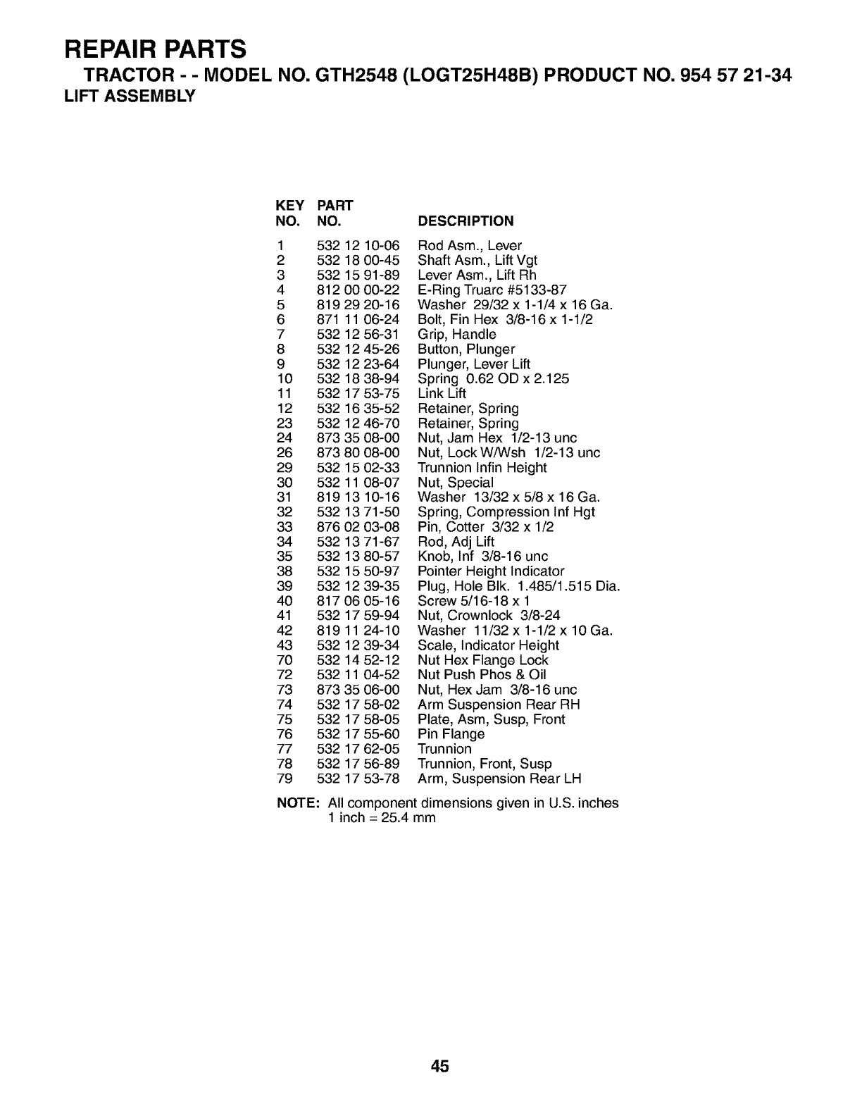
REPAIR PARTS
TRACTOR --MODEL NO. GTH2548 (LOGT25H48B) PRODUCT NO. 954 57 21-34
LIFT ASSEMBLY
KEY PART
NO. NO. DESCRIPTION
1 532 12 10-06 Rod Asm., Lever
2 532 18 00-45 Shaft Asm., Lift Vgt
3 532 15 91-89 Lever Asm., Lift Rh
4 812 00 00-22 E-Ring Truarc #5133-87
5 819 29 20-16 Washer 29/32 x 1-1/4 x 16 Ga.
6 871 11 06-24 Bolt, Fin Hex 3/8-16x 1-1/2
7 532 12 56-31 Grip, Handle
8 532 12 45-26 Button, Plunger
9 532 12 23-64 Plunger, Lever Lift
10 532 1838-94 Spring 0.62ODx2.125
11 532 17 53-75 Link Lift
12 532 16 35-52 Retainer, Spring
23 532 12 46-70 Retainer, Spring
24 873 35 08-00 Nut, Jam Hex 1/2-13 unc
26 873 80 08-00 Nut, LockWiWsh 1/2-13 unc
29 532 15 02-33 Trunnion Infin Height
30 532 11 08-07 Nut, Special
31 8191310-16 Washer 13/32x5/8x16Ga.
32 532 13 71-50 Spring, Compression Inf Hgt
33 876 02 03-08 Pin, Cotter 3/32 x 1/2
34 532 13 71-67 Rod, Adj Lift
35 532 13 80-57 Knob, Inf 3/8-16 unc
38 532 15 50-97 Pointer Height Indicator
39 532 12 39-35 Plug, Hole BIk. 1.485/1.515 Dia.
40 817 06 05-16 Screw 5/16-18 x 1
41 532 17 59-94 Nut, Crownlock 3/8-24
42 819 11 24-10 Washer 11/32x 1-1/2x 10Ga.
43 532 12 39-34 Scale, Indicator Height
70 532 14 52-12 Nut Hex Flange Lock
72 532 11 04-52 Nut Push Phos & Oil
73 8733506-00 Nut, HexJam 3/8-16unc
74 532 17 58-02 Arm Suspension Rear RH
75 532 17 58-05 Plate, Asm, Susp, Front
76 532 17 55-60 Pin Flange
77 532 17 62-05 Trunnion
78 532 17 56-89 Trunnion, Front, Susp
79 532 17 53-78 Arm, Suspension Rear LH
NOTE: All component dimensions given in U.S. inches
1 inch = 25.4 mm
45
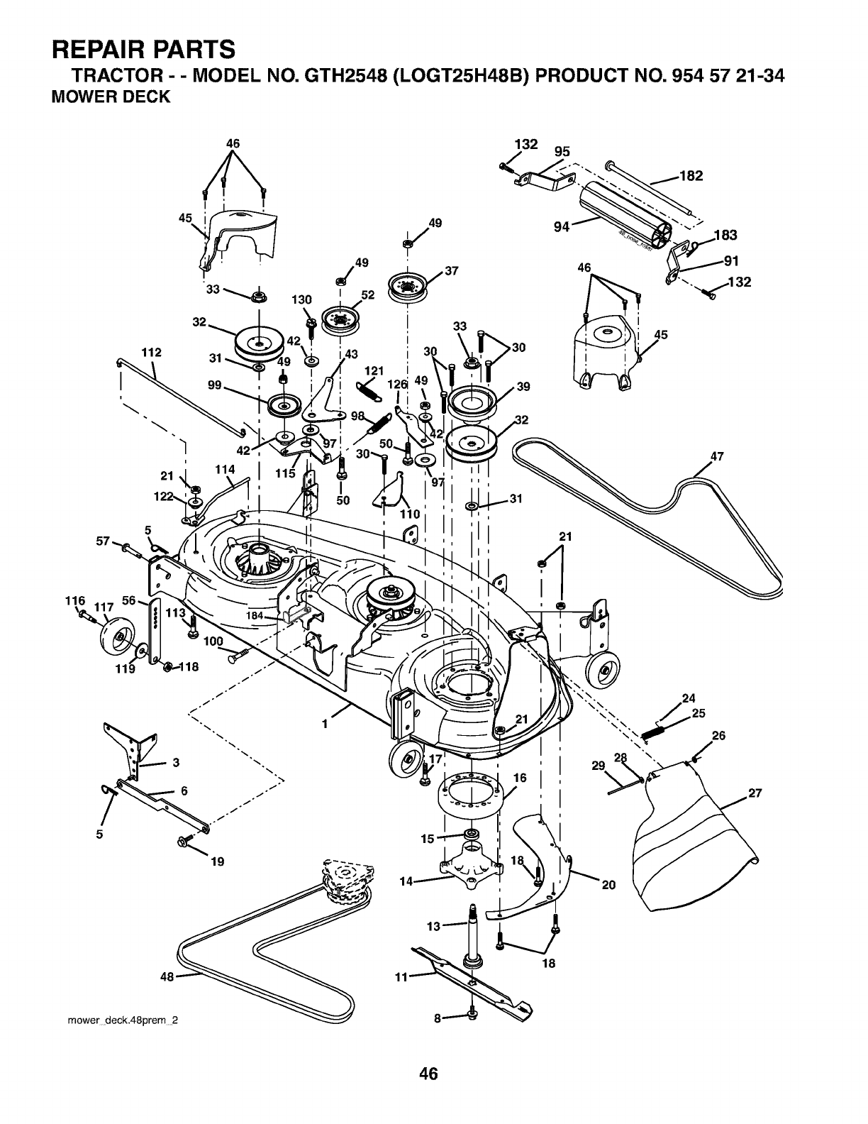
REPAIR PARTS
TRACTOR - - MODEL NO. GTH2548 (LOGT25H48B) PRODUCT NO. 954 57 21-34
MOWER DECK
116
112
I
i
"l
i
21
46
32
31
114
130
i
6
i
11_ 18
46
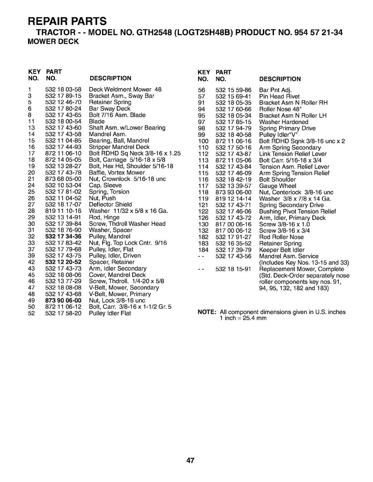
REPAIR PARTS
TRACTOR --MODEL NO. GTH2548 (LOGT25H48B) PRODUCT NO. 954 57 21-34
MOWER DECK
KEY PART KEY PART
NO. NO. DESCRIPTION NO. NO. DESCRIPTION
1 532 18 03-58 Deck Weldment Mower 48 56 532 15 59-86
3 532 17 89-15 Bracket Asm., Sway Bar 57 532 15 69-41
5 532 12 46-70 Retainer Spring 91 532 18 05-35
6 532 17 80-24 Bar Sway Deck 94 532 17 60-66
8 532 17 43-65 Bolt 7/16 Asm. Blade 95 532 18 05-34
11 532 18 00-54 Blade 97 532 17 85-15
13 532 17 43-60 Shaft Asm. w/Lower Bearing 98 532 17 94-79
14 532 17 43-58 Mandrel Asm. 99 532 18 40-58
15 532 11 04-85 Bearing, Ball, Mandrel 100 872 11 06-16
16 532 17 44-93 Stripper Mandrel Deck 110 532 17 50-16
17 872 11 06-10 Bolt RDHD Sq Neck 3/8-16 x 1.25 112 532 17 43-87
18 872 14 05-05 Bolt, Carriage 5/16-18 x 5/8 113 872 11 05-06
19 532 13 28-27 Bolt, Hex Hd, Shoulder 5/16-18 114 532 17 43-84
20 532 17 43-78 Baffle, Vortex Mower 115 532 17 46-09
21 873 68 05-00 Nut, Crownlock 5/16-18 unc 116 532 18 42-19
24 532 10 53-04 Cap, Sleeve 117 532 13 39-57
25 532 17 81-02 Spring, Torsion 118 873 93 06-00
26 532 11 04-52 Nut, Push 119 819 12 14-14
27 532 18 17-07 Deflector Shield 121 532 17 43-71
28 81911 10-16 Washer 11/32x5/8x16Ga. 122 5321746-06
29 532 13 14-91 Rod, Hinge 126 532 17 43-72
30 532 17 39-84 Screw, Thdroll Washer Head 130 817 00 06-16
31 532 18 76-90 Washer, Spacer 132 817 00 06-12
32 532 17 34-36 Pulley, Mandrel 182 532 17 91-27
33 532 17 83-42 Nut, Fig.Top LockCntr. 9/16 183 532 16 35-52
37 532 17 79-68 Pulley, Idler, Flat 184 532 17 39-79
39 532 17 43-75 Pulley, Idler, Driven - - 532 17 43-56
42 532 12 20-52 Spacer, Retainer
43 532 17 43-73 Arm, Idler Secondary - - 532 18 15-91
45 532 18 08-06 Cover, Mandrel Deck
46 532 13 77-29 Screw, Thdroll. 1/4-20 x 5/8
47 532 18 08-08 V-Belt, Mower, Secondary
48 532 17 43-68 V-Belt, Mower, Primary
49 873 90 06-00 Nut, Lock 3/8-16 unc
50 87211 06-12 Bolt, Carr. 3/8-16x1-1/2Gr. 5
52 532 17 58-20 Pulley Idler Flat
Bar Pnt Adj.
Pin Head Rivet
Bracket Asm N Roller RH
Roller Nose 48"
Bracket Asm N Roller LH
Washer Hardened
Spring Primary Drive
Pulley Idler"V"
Bolt RDHD Sqnk 3/8-16 unc x 2
Arm Spring Secondary
Link Tension Relief Lever
Bolt Carr. 5/16-18 x 3/4
Tension Asm. Relief Lever
Arm Spring Tension Relief
Bolt Shoulder
Gauge Wheel
Nut, Centerlock 3/8-16 unc
Washer 3/8 x 7/8 x 14 Ga.
Spring Secondary Drive
Bushing Pivot Tension Relief
Arm, Idler, Primary Deck
Screw 3/8-16 x 1.0
Screw 3/8-16 x 3/4
Rod Roller Nose
Retainer Spring
Keeper Belt Idler
Mandrel Asm. Service
(Includes Key Nos. 13-15 and 33)
Replacement Mower, Complete
(Std. Deck-Order separately nose
roller components key nos. 91,
94, 95, 132, 182 and 183)
NOTE: All component dimensions given in U.S. inches
1 inch = 25.4 mm
47

SERVICE NOTES
48

SERVICE NOTES
49

Z
LU
LU
>.
Z
.<
E
E
s
Z
m
8
5
I
? ','
5€--
J i
_ 5a
C_
O.__
_z 8_
_o _o_O
-o __
_ _ .=
- "8 b ._
"E
o@
o_ '_o=
C0wl- c_.p
wOO o c_
rrl.- n "_ "o
o_ _
O_ i-- n"
_o
_°_
m _I c
_o.__ o
(D d_
og oo
"o d_
_ o
_-s },
o
I=--
Z
_o
#,
b._- __
_=°
-_-
-_=E_
_o_
_rmE_
E
o
9
r_
E
8
b
b
_e
_E
ml
P_E
wl
."I.:
w_
1,1,1_
'-7
50

O1
SUGGESTED GUIDE FOR SIGHTING SLOPES FOR SAFE OPERATION
-''-'----_ o°
ONLY RIDE UP AND DOWN HILL,
NOT ACROSS HILL
15 DEGREES MAX.
_ARNING: To avoid serious injury, operate your tractor up and
down the face of slopes, never across the face. Do not mow
slopes greater than 15 degrees. Make turns gradually to prevent
tipping or loss of control. Exercise extreme caution when
changing direction on slopes.
1. Fold this page along dotted line indicated above.
2. Hold page before you so that its left edge is vertically parallel to a tree
trunk or other upright structure.
3. Sight across the fold in the direction of hill slope you want to measure.
4. Compare the angle of the fold with the slope of the hill.
iiiiiiiiiiiiiiiiiiiiii

Husqvarna
532 19 08-44 02.02.04 RD Printed in U.S.A.
