HXI 00000-30-30 User Manual Installation manual Rev1
HXI, LLC Installation manual Rev1
UserManual.wiki
>
HXI
>
00000-30-30 User Manual
>
Installation manual
Contents
1.
Users Manual
2.
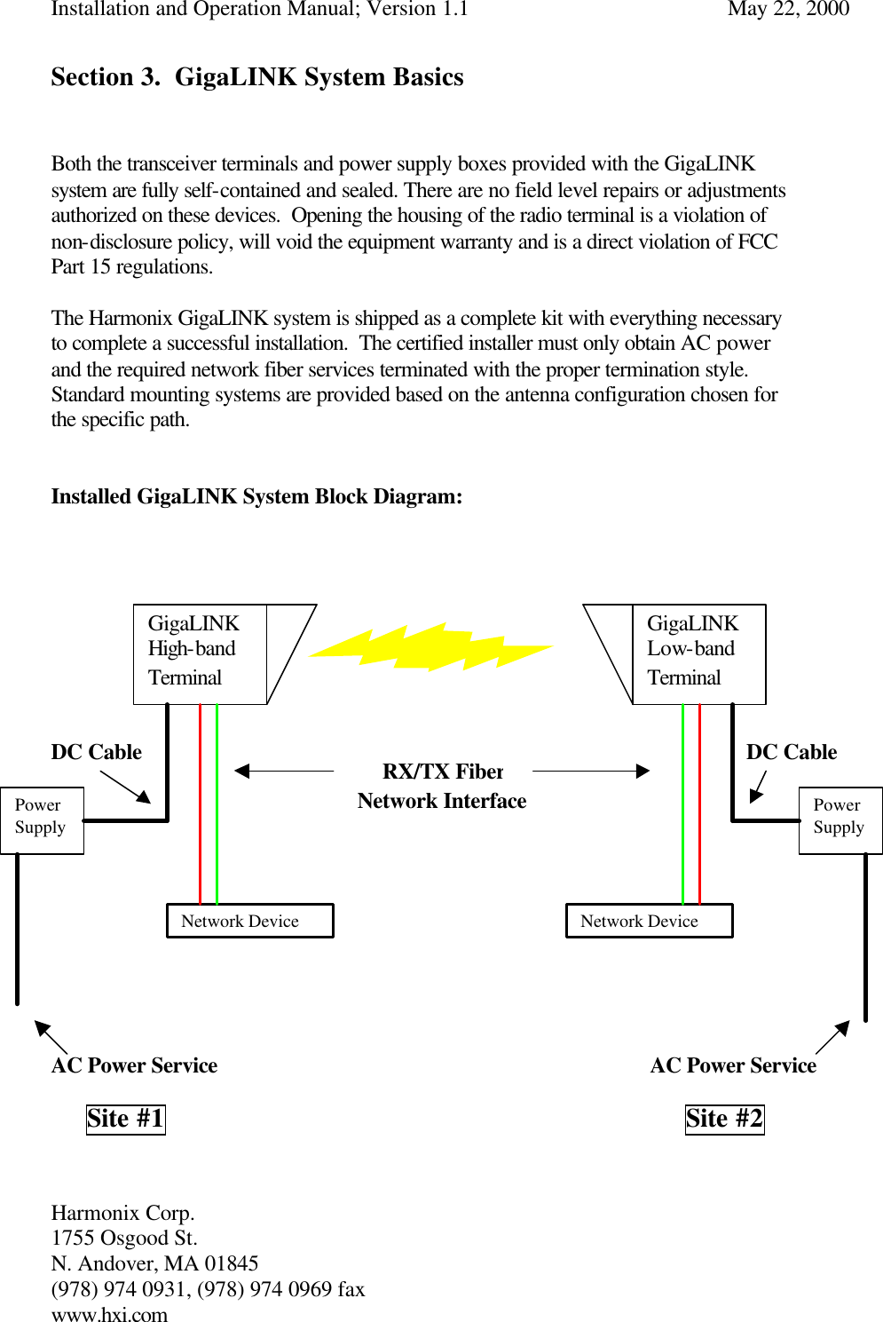
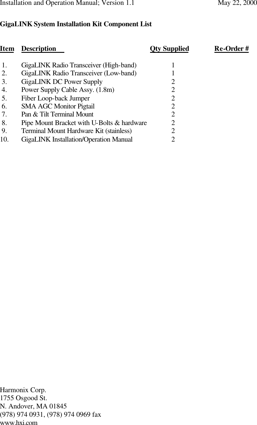
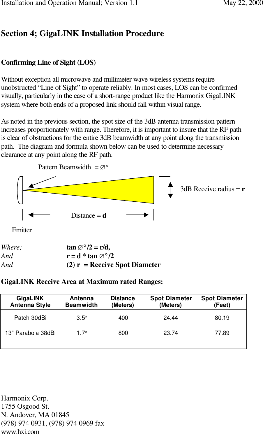
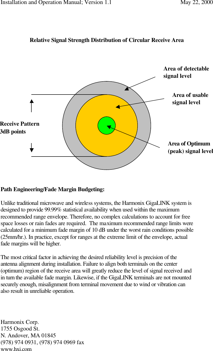
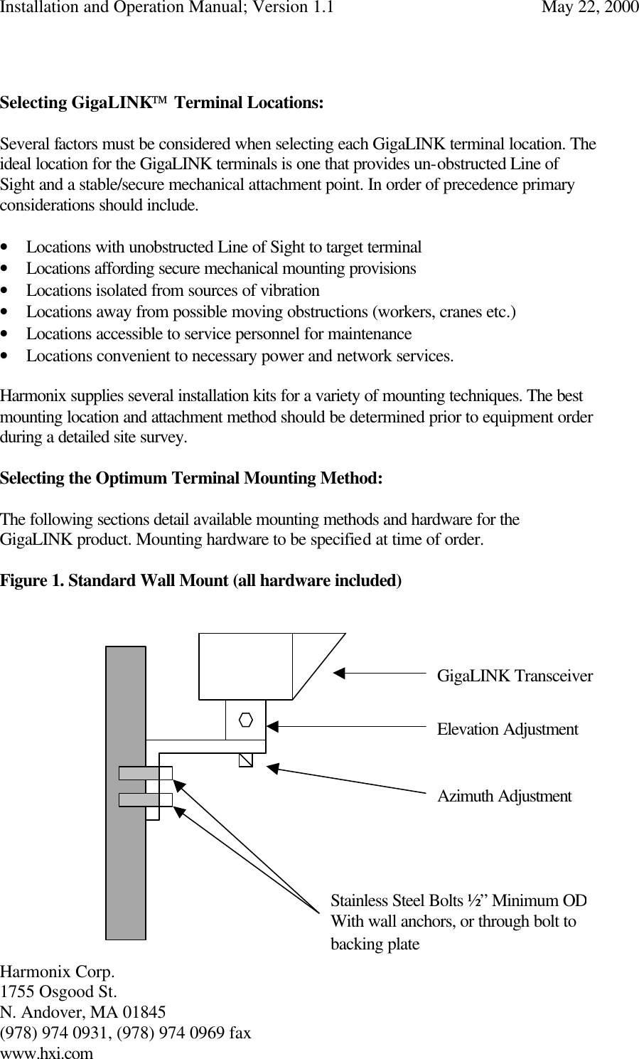
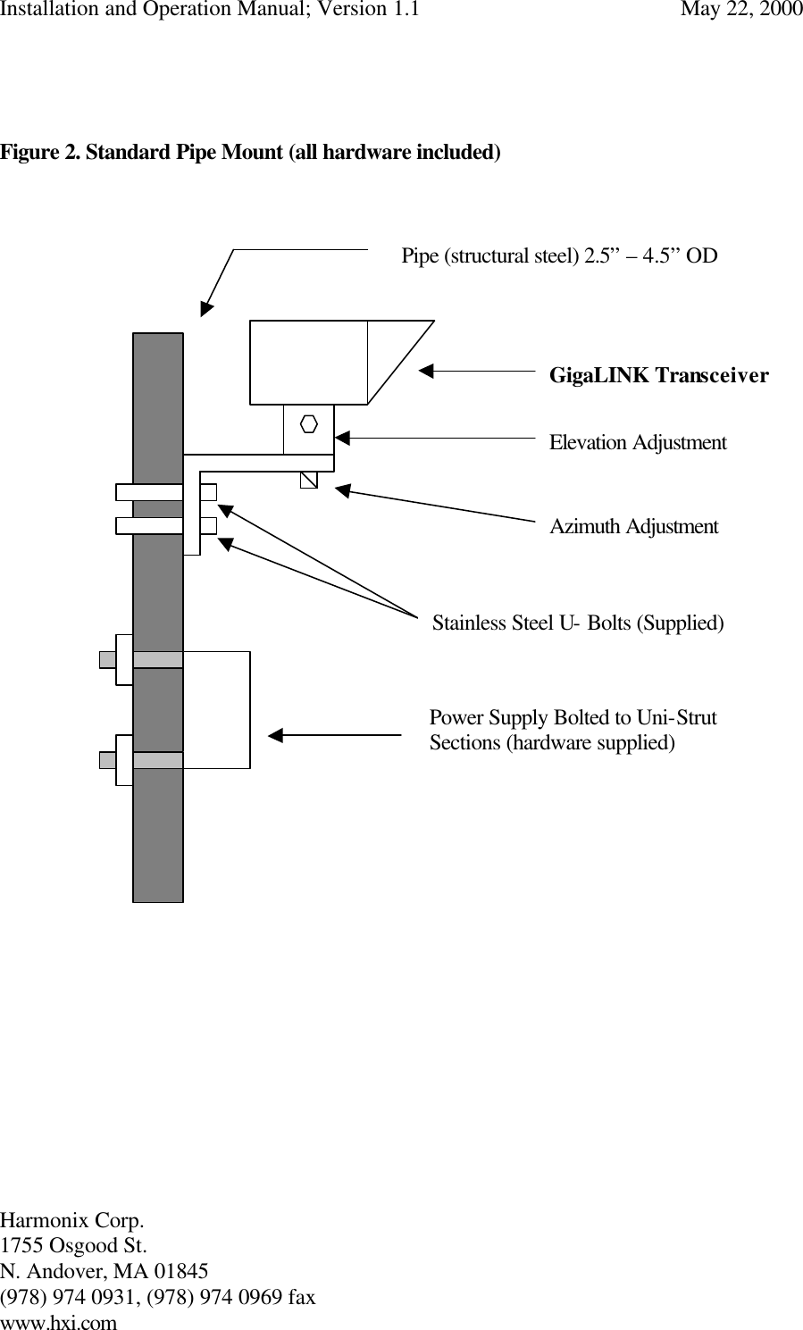
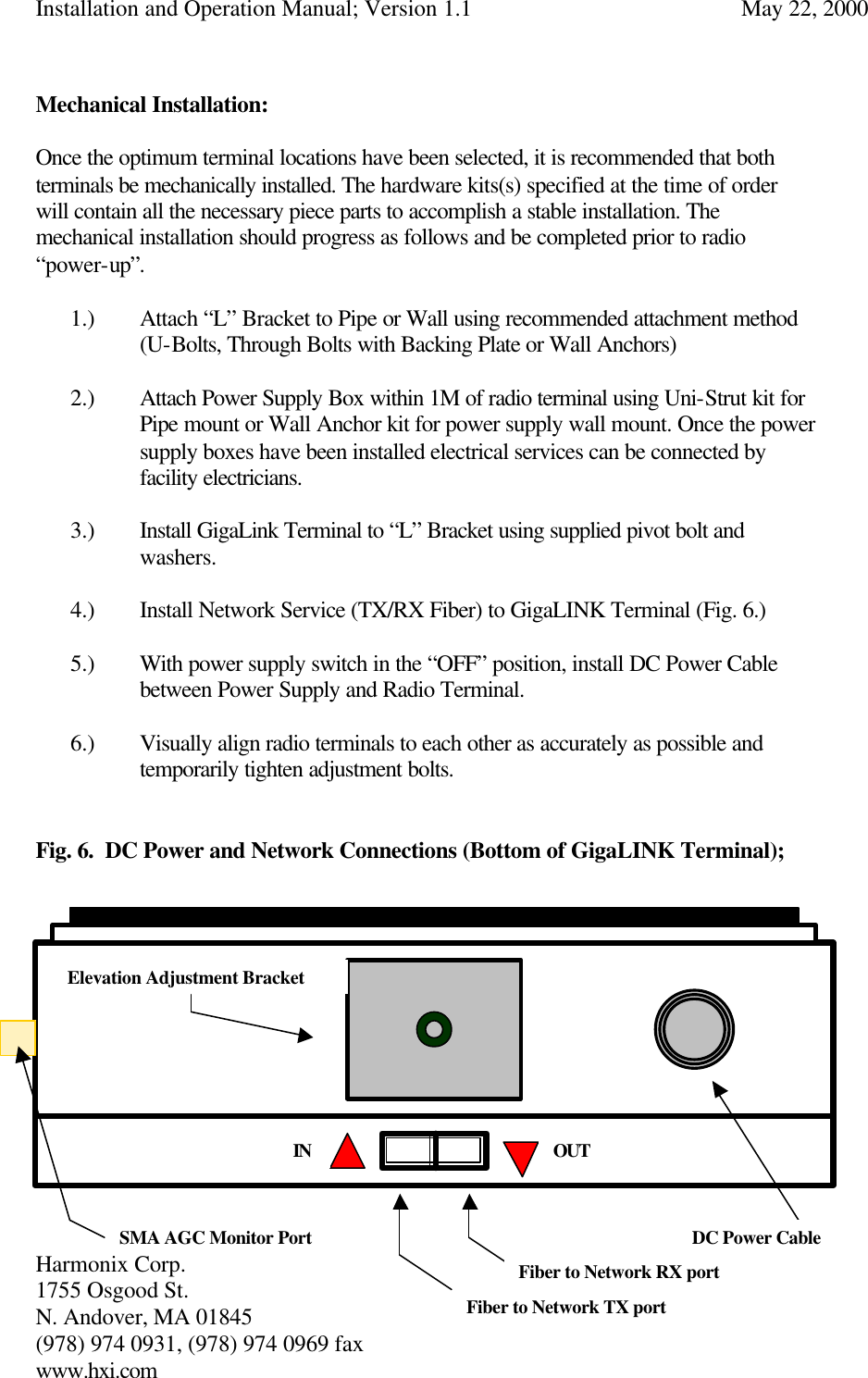
Installation manual
Installation manual
Navigation menu
Upload a User Manual
Namespaces
Wiki Guide
HTML
PDF
Info
Views
User Manual
Discussion / Help
Navigation