HXI 00001-30-30 Millimeter wave transmitter User Manual FSIMDR
HXI, LLC Millimeter wave transmitter FSIMDR
UserManual.wiki
>
HXI
>
00001 30 30 User Manual
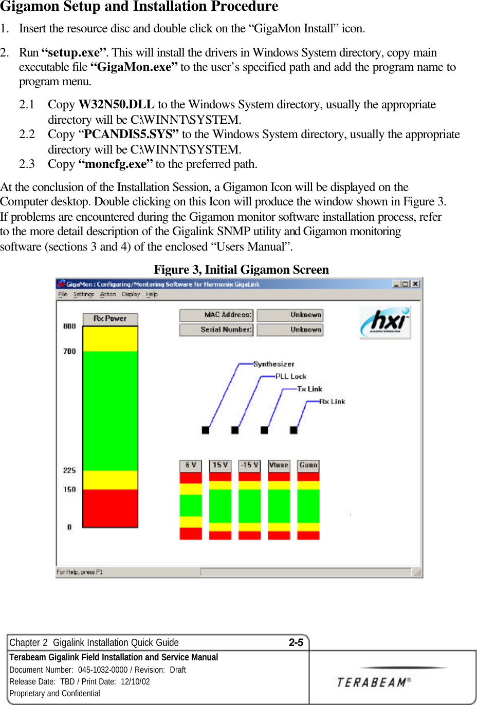
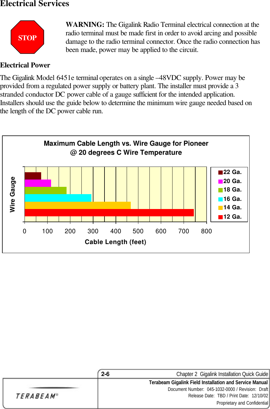
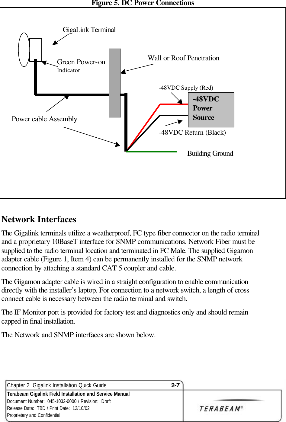
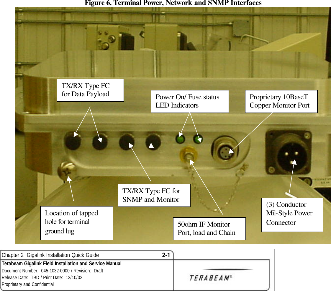
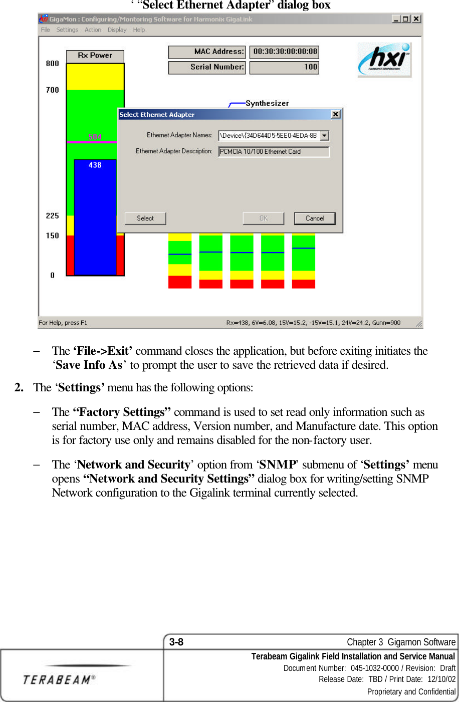
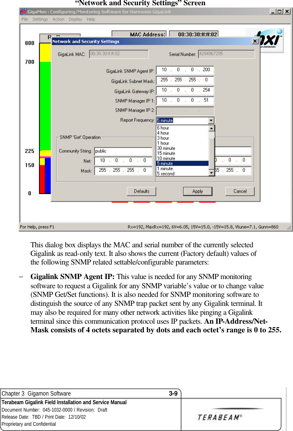
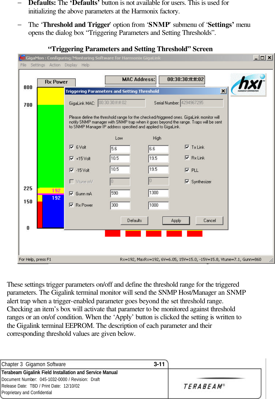
Users Manual
Navigation menu
Upload a User Manual
Namespaces
Wiki Guide
HTML
PDF
Info
Views
User Manual
Discussion / Help
Navigation