HXI 00002-30-30 Gigalink HDTV-Link Transmitter User Manual HDTV Link Rev B
HXI, LLC Gigalink HDTV-Link Transmitter HDTV Link Rev B
HXI >
Manual
Model 6292-2 User Manual # 6932 Rev. B
HXI, LLC
22 Parkridge Road
Haverhill, MA 01835
(978) 521-7304
www.hxi.com
Gigalink HDTV-Link Model 6292-2
Field Installation and Service Manual
THIS DEVICE COMPLIES WITH PART 15 OF THE FCC RULES. OPERATION IS SUBJECT TO
THE FOLLOWING TWO CONDITIONS. (1) THIS DEVICE MAY NOT CAUSE HARMFUL
INTERFERENCE, AND (2) THIS DEVICE MUST ACCEPT ANY INTERFERENCE RECEIVED,
INCLUDING INTERFERENCE THAT MAY CAUSE UNDESIRED OPERATION.
IF THIS PRODUCT IS SUSPECTED OF CAUSING HARMFUL INTERFERENCE WITH OTHER
EQUIPMENT, DISCONTINUE OPERATION IMMEDIATELY AND CONTACT HXI, LLC.
THE OPERATOR OF THIS RADIO EQUIPMENT MUST ENSURE THAT THE ANTENNA IS
LOCATED OR POINTED SUCH THAT IT DOES NOT EMIT AN RF FIELD IN EXCESS OF FCC LIMITS
FOR MAXIMUM PERMISSIBLE EXPOSUE (MPE).
A MINIMUM SEPARATION OF 34cm (13.5”) MUST BE MAINTAINED BETWEEN INDIVIDUALS AND THE
TRANSMITTER MODULE ANTENNA.
FCC ID: O2700002-30-30
Radiation Exposure Warning
A minimum separation of 34cm (13.5”) must be maintained
between Transmitter module antenna and any individual to reduce
the risk of RF radiation exposure above permissible limits.

Model 6292-2 User Manual # 6932 Rev. B
HXI, LLC
22 Parkridge Road
Haverhill, MA 01835
(978) 521-7304
www.hxi.com
Gigalink HDTV-Link Model 6292-2
Field Operation and Service Manual
June 2009
Document Number: 6932 Rev. B
Revision: B
This manual is valid for Gigalink™ HDTV-Link Model 6292-2 Systems
Copyright © 2009 HXI, LLC
All Rights Reserved
Gigalink™ and Gigamon™ are trademarks of HXI, LLC.
Federal Communications Commission (FCC) Compliance Statement
This equipment is designed to comply with the limits for a Class A digital device, pursuant to
Title 47, Volume 1, Part 15.255 of the FCC rules. These limits are designed to provide
reasonable protection against harmful interference when the equipment is operated in a
commercial environment. This equipment generates, uses, and can radiate radio frequency
energy and, if not installed and used in accordance with the field installation and service
manual, could cause interference with radio communications. Furthermore, any changes or
modifications to this equipment without the expressed approval of HXI, LLC are strictly
prohibited and would void the user’s authority to operate the equipment. Operation is
subject to the following two conditions; 1. This device may not cause harmful interference
and 2. This device must accept any interference received, including interference that may
cause undesired operation. If this product is suspected of causing harmful interference with
other equipment, discontinue operation immediately and contact HXI.
The information in this document is subject to change without notice. Although every effort
has been made to make this field installation and service manual accurate and complete,
HXI, LLC assumes no responsibility for any errors that may appear in this document.
HXI, LLC
22 Parkridge Road
Haverhill, MA 01835
(978) 521-7300
Model 6292-2 User Manual # 6932 Rev. B
HXI, LLC
22 Parkridge Road
Haverhill, MA 01835
(978) 521-7304
www.hxi.com
Safety Information
Regulatory Compliance
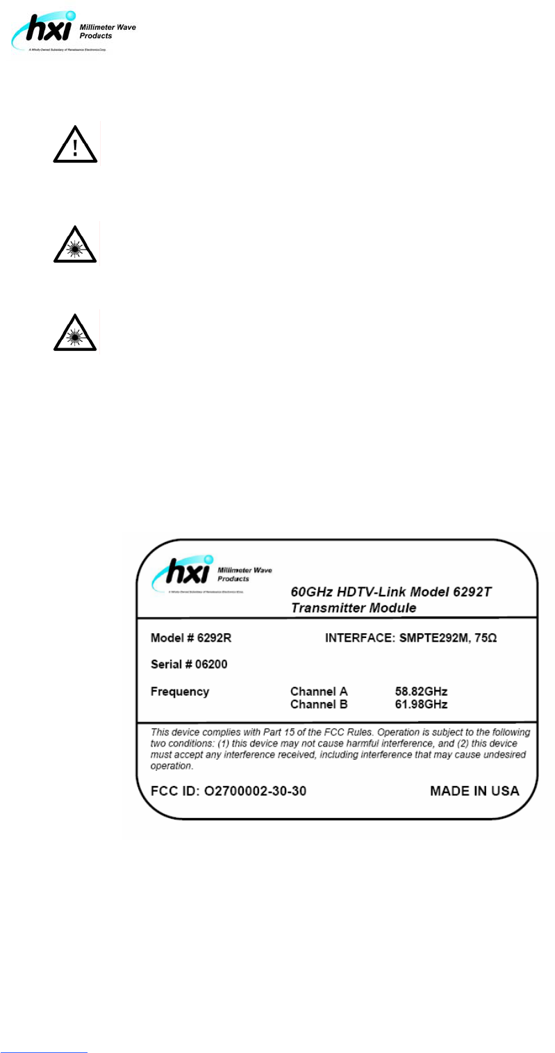
Each Gigalink Model 6292 HDTV-Link terminal displays a label attesting to FCC Part 15.255
compliance. The terminal labels must be conspicuously visible during system operation. Removal of
the terminal labels is prohibited by federal law.
Terminal Regulatory Compliance Label
WARNING – Service of this equipment is only permitted by factory-authorized
personnel who follow approved servicing procedures.
CAUTION – The use of controls or the performance of adjustments or
procedures other than those specified herein are a violation of federal law and
may result in hazardous radiation exposure.
RESTRICTION – The HXI Model 6292-2 HDTV-Link System is authorized for
outdoor use only. Transmitting from inside a building is prohibited under FCC
Part 15.255 (i)

Model 6292-2 User Manual # 6932 Rev. B
HXI, LLC
22 Parkridge Road
Haverhill, MA 01835
(978) 521-7304
www.hxi.com
Table of Contents
1
Introduction
..........................................................................................................1-1
1.1 Purpose ....................................................................................................................1-1
1.2 Organization .............................................................................................................1-1
1.3 Operational Assumptions .........................................................................................1-1
1.4 Job Site Safety .........................................................................................................1-2
1.5 Revisions..................................................................................................................1-2
1.6 Technical Assistance................................................................................................1-2
2 System Overview
.................................................................................................2-1
2.1 General Description..................................................................................................2-1
2.2 Gigalink Components ...............................................................................................2-2
2.3 Gigalink HDTV-Link Model 6292 System Architecture………………………………..2-3
2.4 Maintaining Terminal Pairing……………………………………………………………..2-3
2.5 Gigalink Model 6292 Interfaces………………………………………………………….2-3
3 Pre-operational Planning........................................................................... 3-1
3.1 Pre-deployment Survey............................................................................................3-1
3.2 Location Criteria .......................................................................................................3-1
3.3 Interference Planning for Co-located links ...............................................................3-3
4 Setup and Operation.................................................................................. 4-1
4.1 Deploying the Transmitter and Receiver...................................................................4-1
4.2 Applying terminal power…………………………………………………………………..4-1
4.3 Power Indicators…………………………………………………………………………...4-2
4.4 Terminal alignment………………………………………………………………………...4-3
4.5 Receiver Level Indicator…………………………………………………………………..4-3
4.6 Connecting Video services………………………………………………………………..4-6
4.7 Video Signal Activity Indicators…………………………………………………………...4-7

Model 6292-2 User Manual # 6932 Rev. B
HXI, LLC
22 Parkridge Road
Haverhill, MA 01835
(978) 521-7304
www.hxi.com
Tables
2-1 System Specifications ..............................................................................................2-2
5-1 XLR4 DC Connector Pin-Out…………………………………………………………….5-2
Figures
2-1 Model 6292 Transmitter and Receiver Modules.......................................................2-1
2-3 Gigalink Transceiver Connector Interfaces ..............................................................2-2
3-1 Interference Planning/Receiver Locations................................................................3-3
4-1 Power Indicators.......................................................................................................4-2
4-2 Video Activity Indicators ...........................................................................................4-2

Model 6292-2 User Manual # 6932 Rev. B
HXI, LLC
22 Parkridge Road
Haverhill, MA 01835
(978) 521-7304
www.hxi.com
1. Introduction
1.1 Purpose
The purpose of this document is to present guidance for the operation, and maintenance of
the HXI
®
Gigalink™ HDTV-Link 6292 system, a high-performance, millimeter wave (MMW)
production HDTV Video transport system. The Gigalink HDTV-Link model 6292-2 supports
(2) Independent channels of SMPTE-292M providing error free transport at short to medium
ranges. This system is designed specifically for portable HDTV production video
applications.
This document presents an overview of the Gigalink HDTV-Link Model 6292-2 and its
components and includes discussions of system requirements; installation and assembly;
alignment; routine maintenance; and troubleshooting. Information relevant to safety is also
provided. It is strongly recommended that users read this manual in its entirety prior to
installation.
1.2 Organization
This field installation and service manual is organized into chapters as follows.
• Chapter 1, Introduction. Summarizes the purpose and organization of the document.
• Chapter 2, System Overview. Describes system components.
• Chapter 3, Pre-Deployment Planning. Outlines planning activities to be completed
prior to use, including selecting equipment locations, interface planning design, and
terminal alignment.
• Chapter 4, Setup and Operation. Provides step-by-step procedures for equipment
pointing, power up, and link alignment.
• Chapter 5, Troubleshooting and Repair. Provides troubleshooting guidelines.
1.3 Operational Assumptions
This manual has been prepared to permit technicians who have no prior experience with
MMW radio equipment to deploy, align, operate, troubleshoot, and maintain Gigalink HDTV-
Link system. It is assumed that individuals using this manual are knowledgeable and
experienced in the following areas:
• Operation of point to point of wireless systems requiring unobstructed Line of Sight
• HDTV production video equipment, specifically the SMPTE292M protocol and
associated 75ohm interfaces
• Basic problem-isolation and troubleshooting skills

Model 6292-2 User Manual # 6932 Rev. B
HXI, LLC
22 Parkridge Road
Haverhill, MA 01835
(978) 521-7304
www.hxi.com
1.4 Job Site Safety
Operation of the Gigalink HDTV-Link system may require activities, such operation from
elevated locations, which, if done improperly, could pose a safety hazard to the operator.
The operator is responsible for compliance with all applicable laws, regulations, and safety
practices. Furthermore, in general, employers are responsible for the safety of their
employees and must comply with all applicable worker safety regulations, including the need
to provide training and personal protective equipment.
1.5 Revisions
Changes to this manual may be made from time to time. When this occurs, these changes
will be issued as errata and posted on the HXI support site (www.HXI.com). Customers are
advised to check the Web site periodically and prior to installation for applicable errata.
1.6 Technical Assistance
HXI, LLC maintains a technical support staff to answer questions and provide guidance
regarding installation and service.
Before calling for support, locate and record the specific model number and four-digit serial
number located on the terminal label. Providing this information with the initial contact will
help facilitate responsive support.
For calls from the United States and Canada, and international calls the number is 1-(978)
521-7304
On line support is also available at www.hxi.com
Model 6292-2 User Manual # 6932 Rev. B
HXI, LLC
22 Parkridge Road
Haverhill, MA 01835
(978) 521-7304
www.hxi.com
2. System Overview
2.1 General Description
The Gigalink HDTV-Link Model 6292 wireless HDTV-Link system operates in the FCC Part
15.255 unlicensed allocation in the frequency range of 57.05 to 64.0 GHz. No Federal
Communications Commission (FCC) license or special authorization is required to operate
Gigalink systems.
Note:
Under no circumstances should the protective covers of the Gigalink
transceiver be removed. Any non-authorized removal of the covers or any
attempts to change this equipment are strictly prohibited and will void the
Gigalink warranty as well as the user's authorization to operate this equipment.
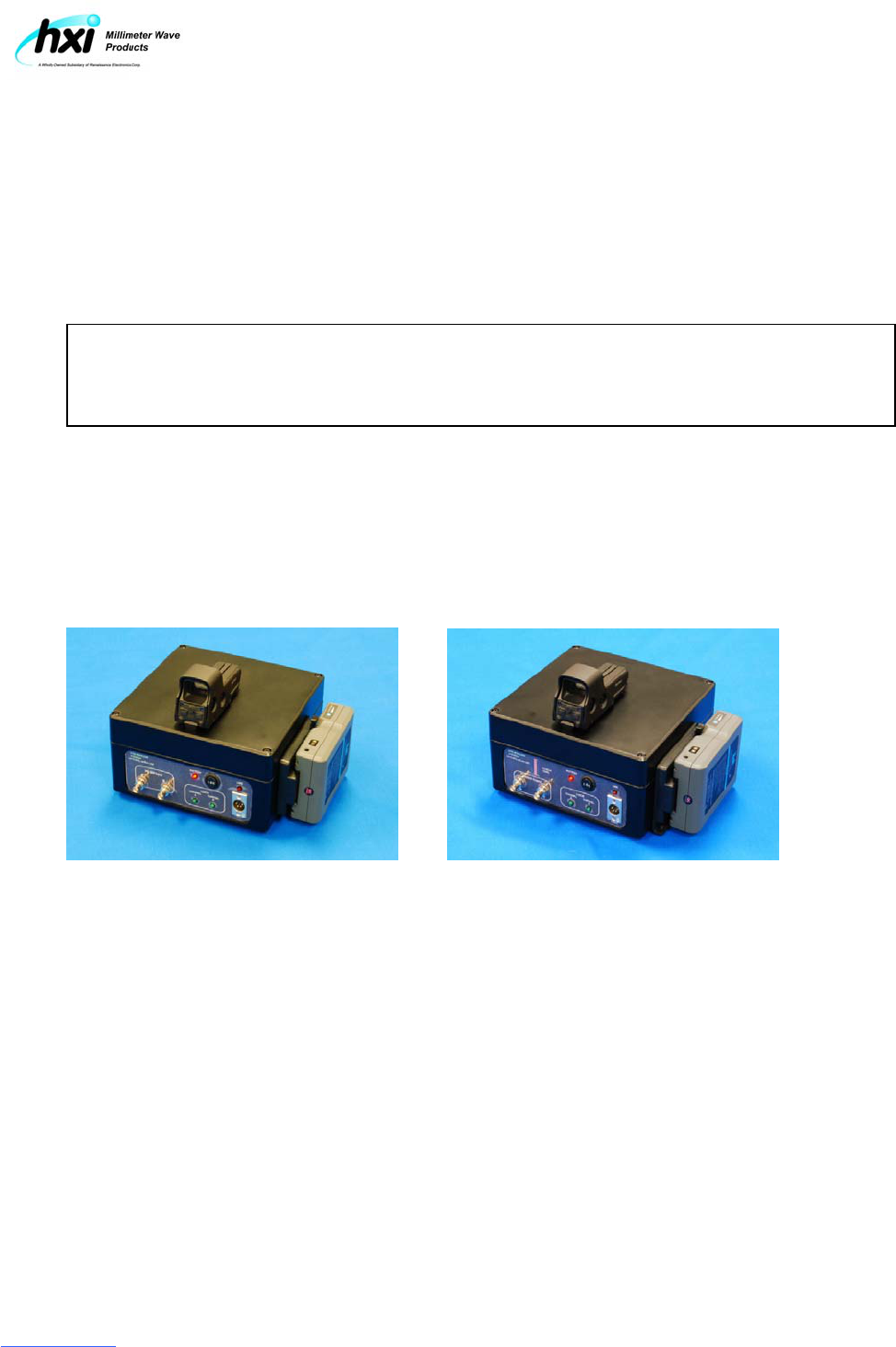
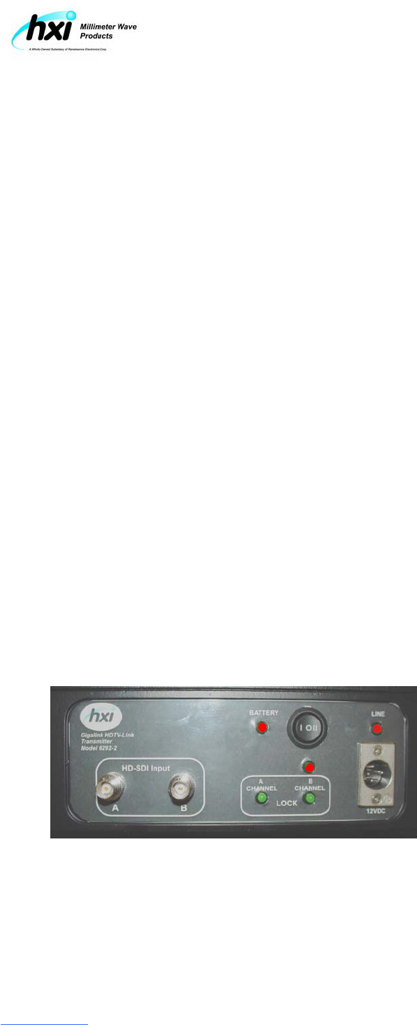
To establish a working link, one Model 6292 transmitter module and one Model 6292
receiver module must be deployed together. Each Gigalink terminal is 12VDC powered,
with power provided via XLR4 interface from customer supply or via an optional V-Mounted
onboard battery. Gigalink HDTV-Link model 6292-2 Transmitter and receiver terminals are
shown in Figure 2-1. System specifications are detailed in Table 2-1
Figure 2-1: HDTV-Link Model 6292
HDTV-Link Model 6292T Transmitter HDTV-Link Model 6292R Receiver
Note: Figure 2-1 Graphic shows transmit and receive terminals equipped with optional V-Mount
battery and alignment sight.
Model 6292-2 User Manual # 6932 Rev. B
HXI, LLC
22 Parkridge Road
Haverhill, MA 01835
(978) 521-7304
www.hxi.com
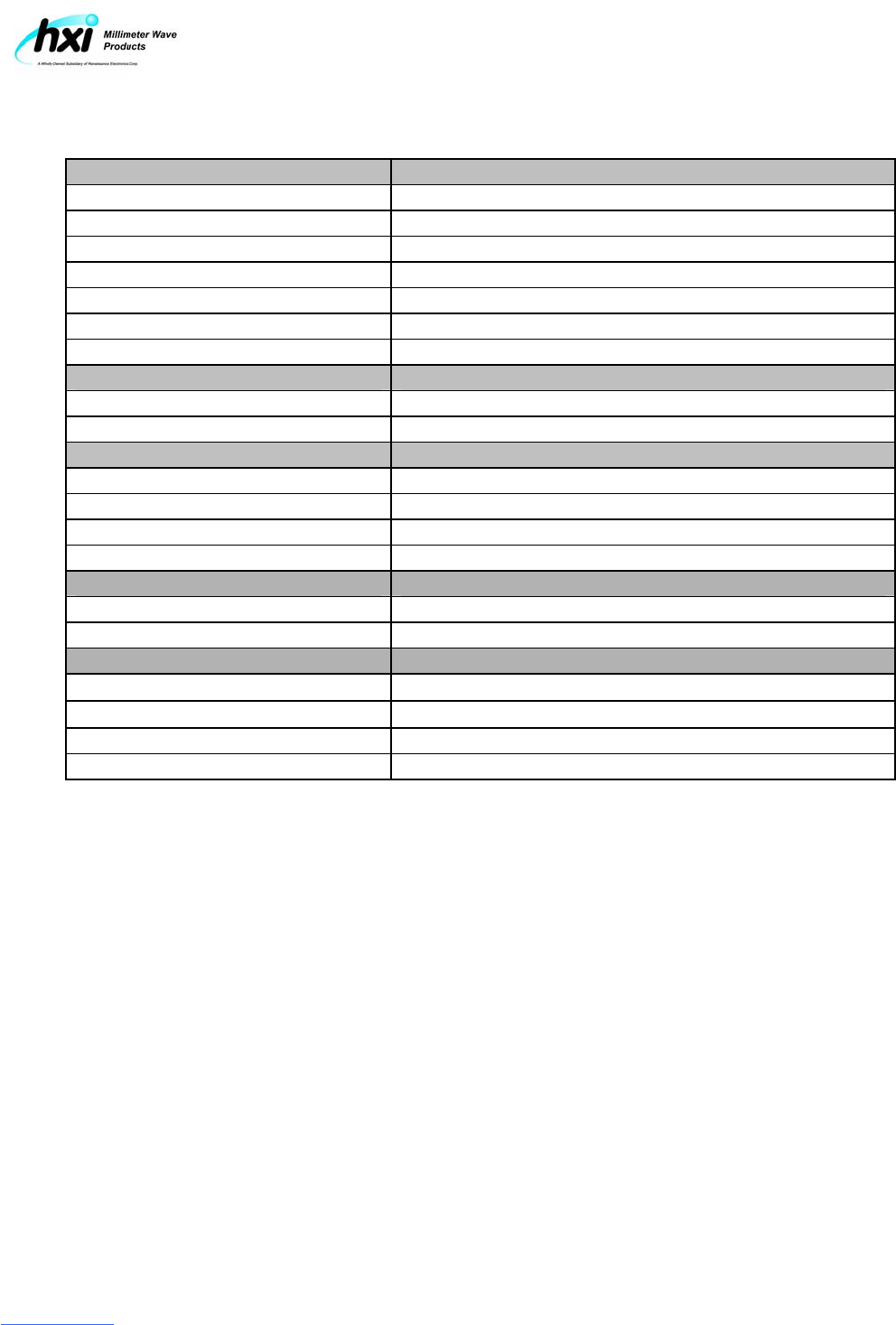
Table 2-1: System Specifications
RF Parameters Specification
Frequency of Operation FCC Part 15.255, unlicensed 57-64GHz
TX Channel Carrier Frequency Channel A = 58.82GHz, Channel B = 61.98GHz
Occupied Spectrum/Channel 1,700MHz Max.
TX Power (each Channel) 4mW (+6dBm) antenna injection
Antenna Gain +32dBi minimum TX and RX
Antenna Beam width (@-3dB) 5° TX and RX both azimuth and elevation
Operating Range (moderate rain) 10 to 500 meters
Interface Parameters Specification
Data Throughput (each Channel) Full line rate SMPTE292M, SMPTE372M, 4.4.2, 4 protocols
Payload Interface (each channel) SMPTE292M (1.48Gbps) BNC 75Ω
Power requirements Specification
DC Power Interface XLR4 type power connector
DC input voltage range 12 VDC nominal (9.5 VDC to 15 VDC)
DC power consumption Transmitter = 15W, Receiver =18W
Maximum current load Transmitter = 1.2A, Receiver = 1.5A
Mechanical Specification
Transceiver weight 11lbs (5Kg)
Transceiver dimensions (H x W x D) 9.5”L x 9.5”W x 4.75”H (240mm x 240mm x 120mm)
Environmental Parameter
Operating Temperature 32° F to 122° F (0° C to 60° C)
Storage Temperature -22° F to 185° F (-30° C to 85° C)
Humidity up to 95%, non-condensing
Enclosure Rating IPC67, NEMA
2.2 Gigalink HDTV-Link Model 6292 Components
Each Gigalink HDTV-Link Model 6292 kit includes transmitter and receiver modules, a
user’s manual and comes ready for deployment (see Figure 2-1). These components are
described in detail in the subsections that follow. The primary components of the Gigalink
include:
• Gigalink Transmitter module #6292T
• Gigalink Receiver module #6292R
• HDTV-Link Model 6292 User’s Guide document # 6932
Model 6292-2 User Manual # 6932 Rev. B
HXI, LLC
22 Parkridge Road
Haverhill, MA 01835
(978) 521-7304
www.hxi.com
2.3 Gigalink HDTV-Link Model 6292 System Architecture
Each full Gigalink HDTV-Link Model 6292 System consists of (1) transmitter and (1) receiver
module that must be aligned with each other during operation to maintain maximum signal
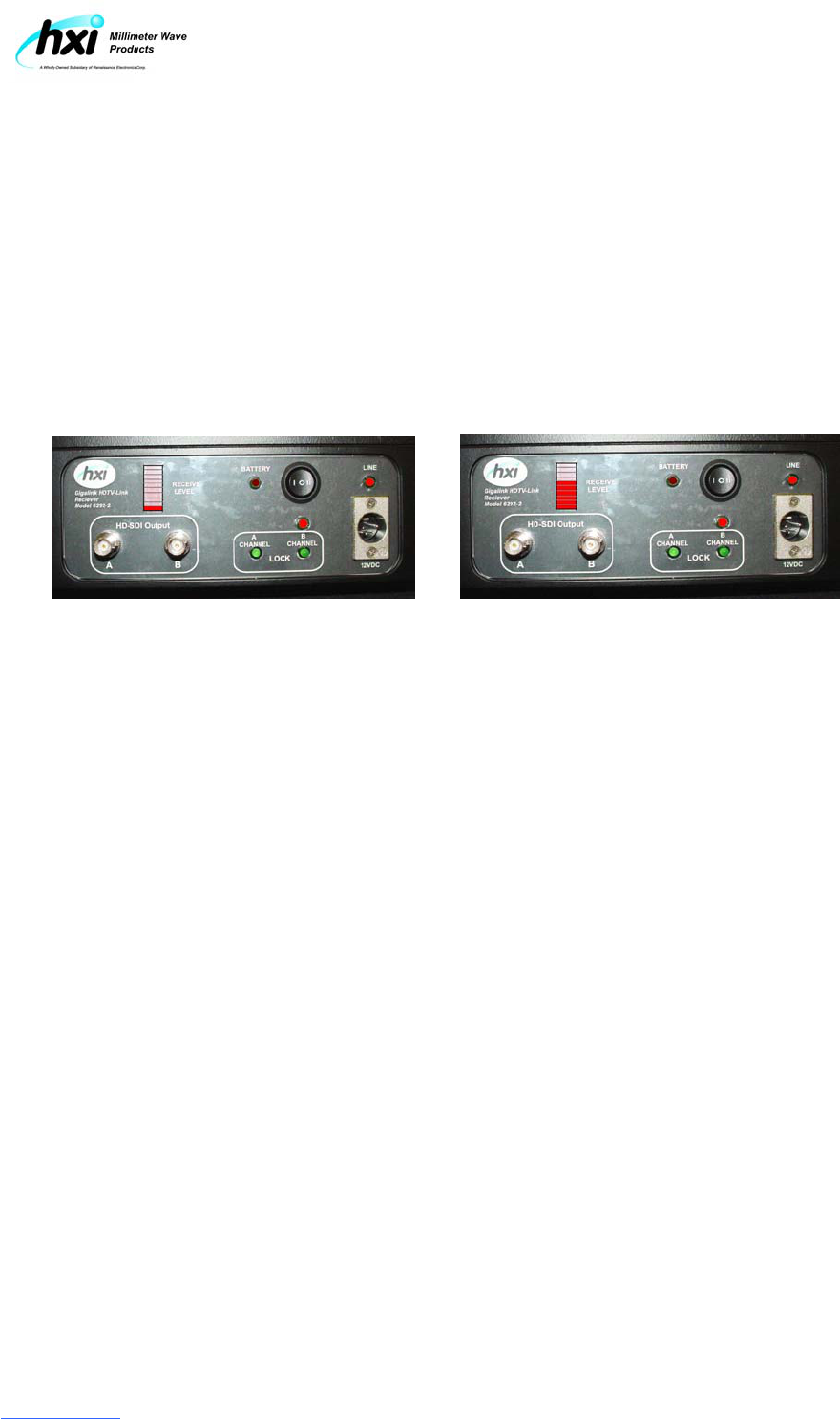
strength for error-free wireless connectivity. The receiver module is equipped with a receive
level Bar Graph indicator to simplify terminal alignment
Each Model 6292 system (link) is shipped as a matched transmitter/receiver pair. Each link
is 100% operationally tested with operating parameters recorded and kept on file at the HXI
manufacturing facility. Terminal pairing is accomplished through a simple serial number
format with the transmitter module identified by an even 4-digit serial number with the next,
higher, odd, number in sequence to identify its paired receiver module.
2.4 Maintaining Terminal Pairing
Because each system is tested and shipped as a “Link”, the original terminal pairing must be
preserved to establish and maintain traceability back to the original production acceptance
test results and recorded performance data. While pairing any Model 6292 transmitter with
any model 6292 receiver will result in an operational link such mixing of pairs will leave the
link operation unsupported by HXI technical support from lack of reference data.
All malfunctioning or defective systems should be replaced as links not as individual
modules. If a system is believed to be defective HXI Technical support should be contacted
for assistance and if necessary an RMA# for return/replacement of the defective equipment.
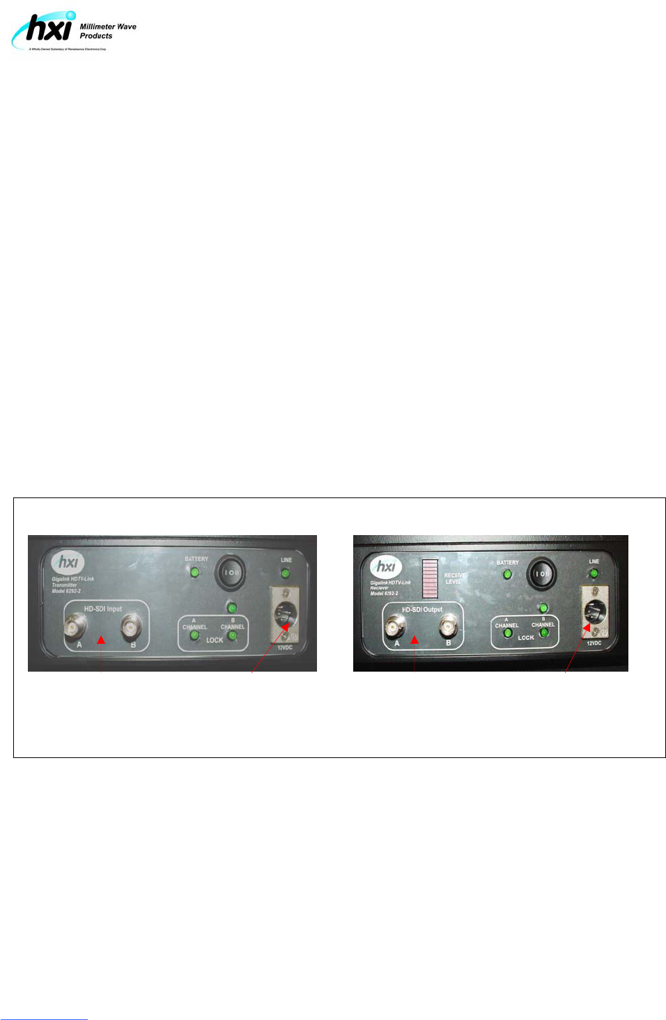
Figure 2-3: Gigalink HTTV-Link Model 6292 Interfaces
Model 6292T Transmitter Model 6292R Receiver
HD-SDI XLR4 HD-SDI XLR4
Inputs A and B Power Receptacle Outputs A and B Power Receptacle
Model 6292-2 User Manual # 6932 Rev. B
HXI, LLC
22 Parkridge Road
Haverhill, MA 01835
(978) 521-7304
www.hxi.com
3. Pre-operational Planning
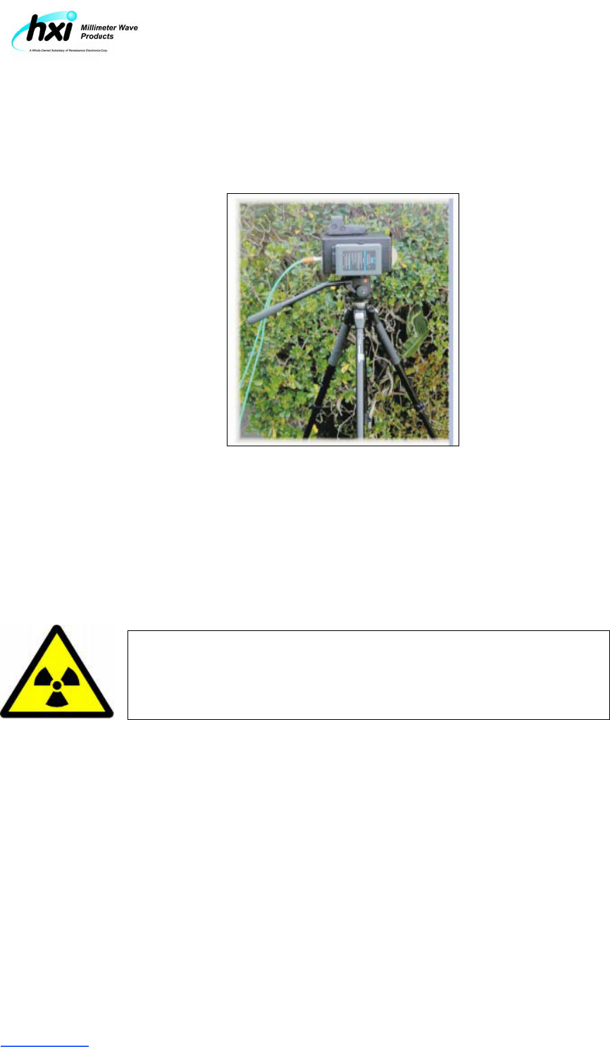
3.1 Pre-deployment Survey
It is recommended that users perform an onsite survey and complete pre-installation
planning prior to actual operation of the Gigalink HDTV system. Pre-operational planning
tasks include:
• Selecting appropriate locations for all equipment based on the location criteria (see
Section 3.1)
• Identifying and locating (as necessary) a suitable mounting structure (i.e. tripod) for each
terminal
• Locate necessary services (e.g., power source and cabling) that will be required prior to
the operation
• Obtaining any necessary permissions and verify regulatory and safety compliance.
• Verifying the type and configuration of any equipment to be used with the Gigalink
HDTV-Link system
• Determining the best terminal locations to provide unobstructed “Line of Sight” and
minimum separation of personnel from the transmit module antenna.
• Identifying additional tools and equipment, if any, that will be needed to support
equipment installation
It is also recommended that installers prepare sketches that show where all system
components will be located and how cables will be routed between components.
Pre-deployment planning is essential to avoid unanticipated problems and failures in system
operation during actual operation.
Radiation Exposure Warning
A minimum separation of 34cm (13.5”) must be maintained
between Transmitter module antenna and any individual to reduce
the risk of RF radiation exposure above permissible limits.
Model 6292-2 User Manual # 6932 Rev. B
HXI, LLC
22 Parkridge Road
Haverhill, MA 01835
(978) 521-7304
www.hxi.com
3.2 Location Criteria
Considerations for locating the Gigalink HDTV system include the following:
• Line of Sight. The location of the transceiver must have an unobstructed line of sight to
the opposite end of the link. Potential obstructions include but are not limited to the
following:
− Onsite Obstructions. The transmitter and receiver modules should be sufficiently
high and at a location such that the line of sight will not be compromised by
conditions or activities beyond the control of the operator. At a minimum, the line of
sight should clear the edge of any vertical and horizontal obstructions or areas
occupied by people by no less than 8’. Possible obstructions include Foliage,
Vehicles, or personnel moving through the RF Path.
− Obstructions across the RF Link. The line of sight across the RF Path must clear
all intervening obstacles. Any even a partial blockage of the RF signal may render
the wireless link inoperable.
• Mounting Surface. Each Gigalink Model 6292 transmitter and receiver terminal are
designed to be mounted to a standard tripod system. The tripods used must be sturdy
enough to support the weight of each terminal and stable enough to prevent terminal
movement during normal operation.
• Environmental Conditions. The Gigalink Model 6292 terminals are weatherproof but
not watertight. The terminals must be located away from standing water, severe rain
splash, or snow buildup.
• Regulatory Compliance and Permissions. The selected transceiver location must
comply with all applicable regulatory and zoning requirements as well as rules and
restrictions imposed by the location owner or manager.
Note:
The user is responsible for identifying and complying with all applicable
regulatory, zoning, or other restrictions and obtaining the necessary permissions
from the appropriate authorities and facility management prior to installation.
Model 6292-2 User Manual # 6932 Rev. B
HXI, LLC
22 Parkridge Road
Haverhill, MA 01835
(978) 521-7304
www.hxi.com
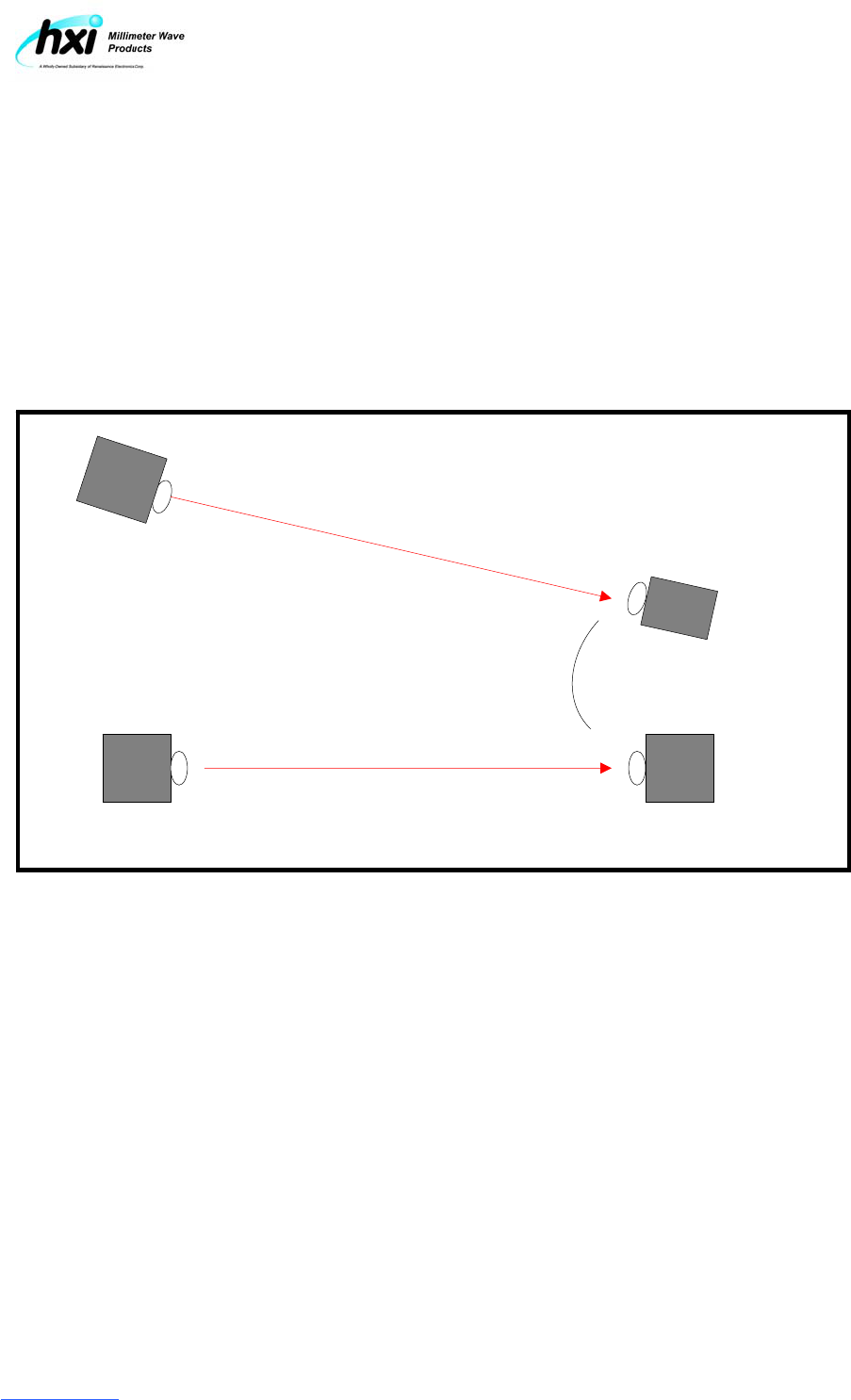
3.3 Interference Planning for Co-located Links
When more than (1) Gigalink HDTV-Link are deployed in the same general area, care must
be taken to prevent RF interference between links. It is especially important to provide
adequate physical or angular separation of the received signal paths at the receiver terminal
locations.
Figure 3.1 provides a guide of how to configure receive terminal locations to avoid RF
interference between co-located links.
Figure 3.1 Locating HDTV-Link terminals for Interference mitigation
HDTV-Link Transmitter
Locations
HDTV-Link Receiver
Locations
Minimum Separation
Angle ≥ 20°
Model 6292-2 User Manual # 6932 Rev. B
HXI, LLC
22 Parkridge Road
Haverhill, MA 01835
(978) 521-7304
www.hxi.com
4. Setup and Operation
4.1 Deploying the Transmitter and Receiver
The HDTV-Link transmitter terminal should be deployed near the associated video
production equipment (Camera) and the HDTV-Link receiver located near the Video editing
facility.
Both Terminals should be attached to suitable mounts or tripods based on earlier survey
instructions and aligned with the antennas facing in the direction of the opposing terminal.
Rough terminal alignment can be accomplished by sighting along the screws located on the
top of the terminal housing or by using the optional alignment scope.
4.2 Applying terminal power
Before applying power to the Gigalink HDTV-Link terminal, make sure the terminal power
switch is in the center “off” position.
12VDC terminal power is applied to the standard XLR4 Power connector receptacle located
on the right back-side of the terminal housing. The power cable should be inserted until the
locking tab engages. When power is present at the XLR4 connector receptacle, the Red
Line Power LED will light.
With power present to the HDTV-Link Terminal, the terminal power switch can be toggled to
the right to power the terminal on. When terminal power is on, the center red LED will
illuminate.
4.3 Power Indicators
Each Gigalink HDTV-Link terminal is equipped with (3) power indicators, one for line power,
one for terminal power and one for optional On-Board battery power.
Figure 4.1 Power Indicators
Model 6292-2 User Manual # 6932 Rev. B
HXI, LLC
22 Parkridge Road
Haverhill, MA 01835
(978) 521-7304
www.hxi.com
4.4 Terminal Alignment
In order to establish a reliable RF link, both HDTV-Link transmitter and receiver terminals
must be precisely aligned. The HDTV-Link receiver terminal is equipped a Bar Graph display
to confirm terminal alignment and signal strength.
With both transmitter and receiver terminals powered on, slowly adjust alignment both
vertically and horizontally until the receiver Signal Bar Graph display reaches the highest
level. It is recommended that two operators work together by incrementally adjusting each
side until the maximum receive level is achieved.
The use of 2-way radios or cell phones will make this task easier. Figure 4.2 shows the
operation of the Receive level Bar Graph Indicator.
Figure 4.2 Receive Level Indicator
Low Indicated Receive level High Indicated Receive Level
4.5 Connecting Video Services
The Gigalink HDTV-Link Model 6292 is equipped to transport (2) independent feeds of
SMPTE292M composite Video/audio. Channels A and B can be operated independently or together
as necessary with no degradation to signal quality.
Two BNC connectors interface with the Video feed cable (Transmitter) or supply the Video feed
cable on the receiver side. All interfaces comply with the SMPTE 75Ω Coaxial cable standard for
maximum cable length if Belden Type 1694A cable is used.
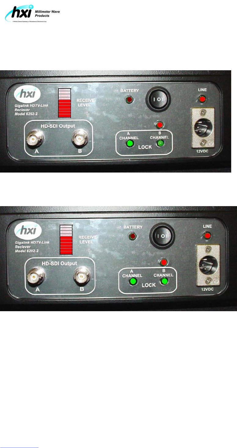
4.6 Video Activity Indicators
Both the Transmitter and receiver Module are equipped with Video Activity Indicators to show active
interfaces. Active interfaces are indicated by a lighted LED above the interface connector. Figure
4.3 depicts normal operation of the Video Activity Indicators.
Model 6292-2 User Manual # 6932 Rev. B
HXI, LLC
22 Parkridge Road
Haverhill, MA 01835
(978) 521-7304
www.hxi.com
Figure 4.3 Video Activity Indicators
Channel “A” Active, Channel “B” Inactive
Channel “A” and Channel “B” Active