HYT Science and Technology Co TC-310U2 Two-way Radio User Manual TC 310 Owner s Manual V01
Shenzhen HYT Science &Technology; Co Ltd Two-way Radio TC 310 Owner s Manual V01
UserManual.wiki
>
HYT Science and Technology Co
>
TC 310U2 User Manual
Users Manual
Navigation menu
Upload a User Manual
Namespaces
Wiki Guide
HTML
PDF
Info
Views
User Manual
Discussion / Help
Navigation
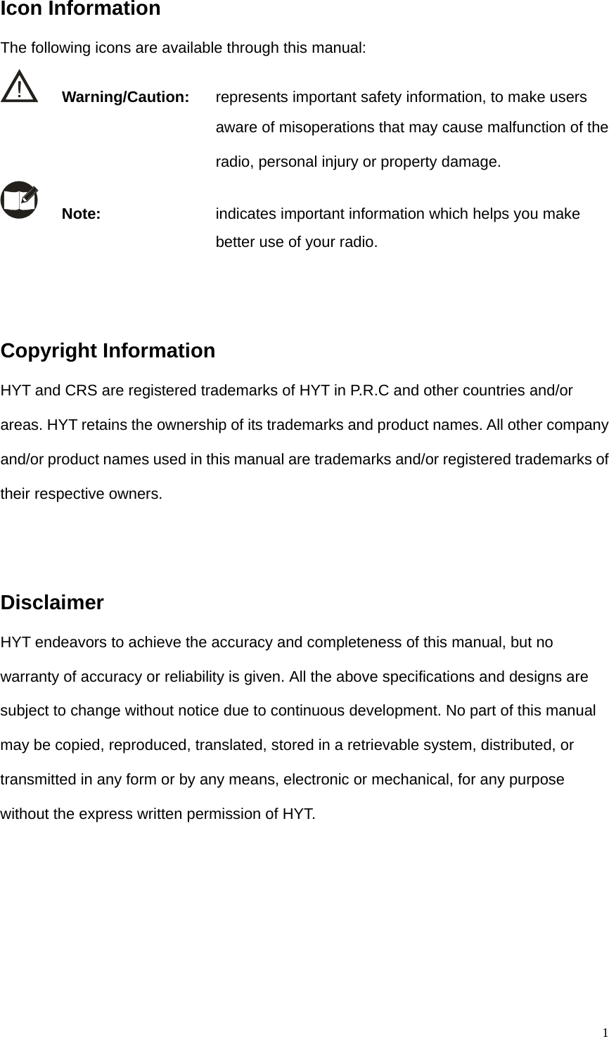
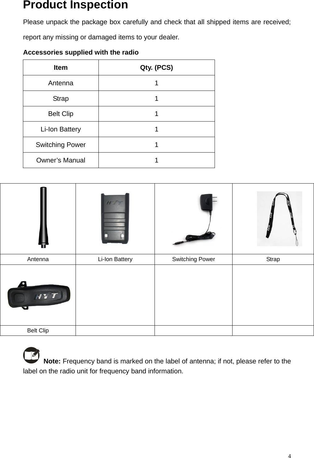
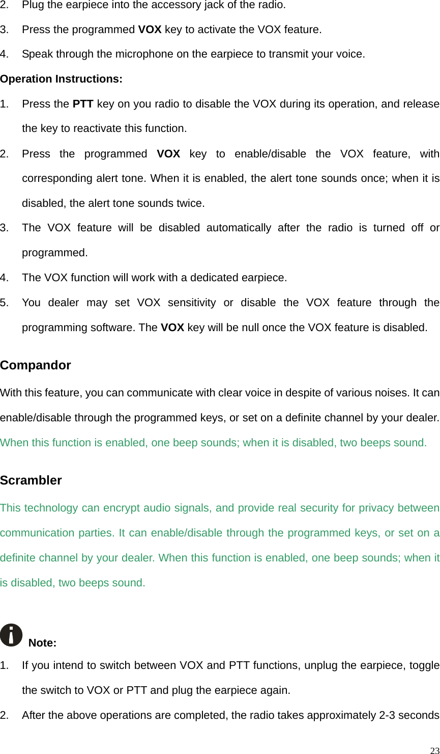
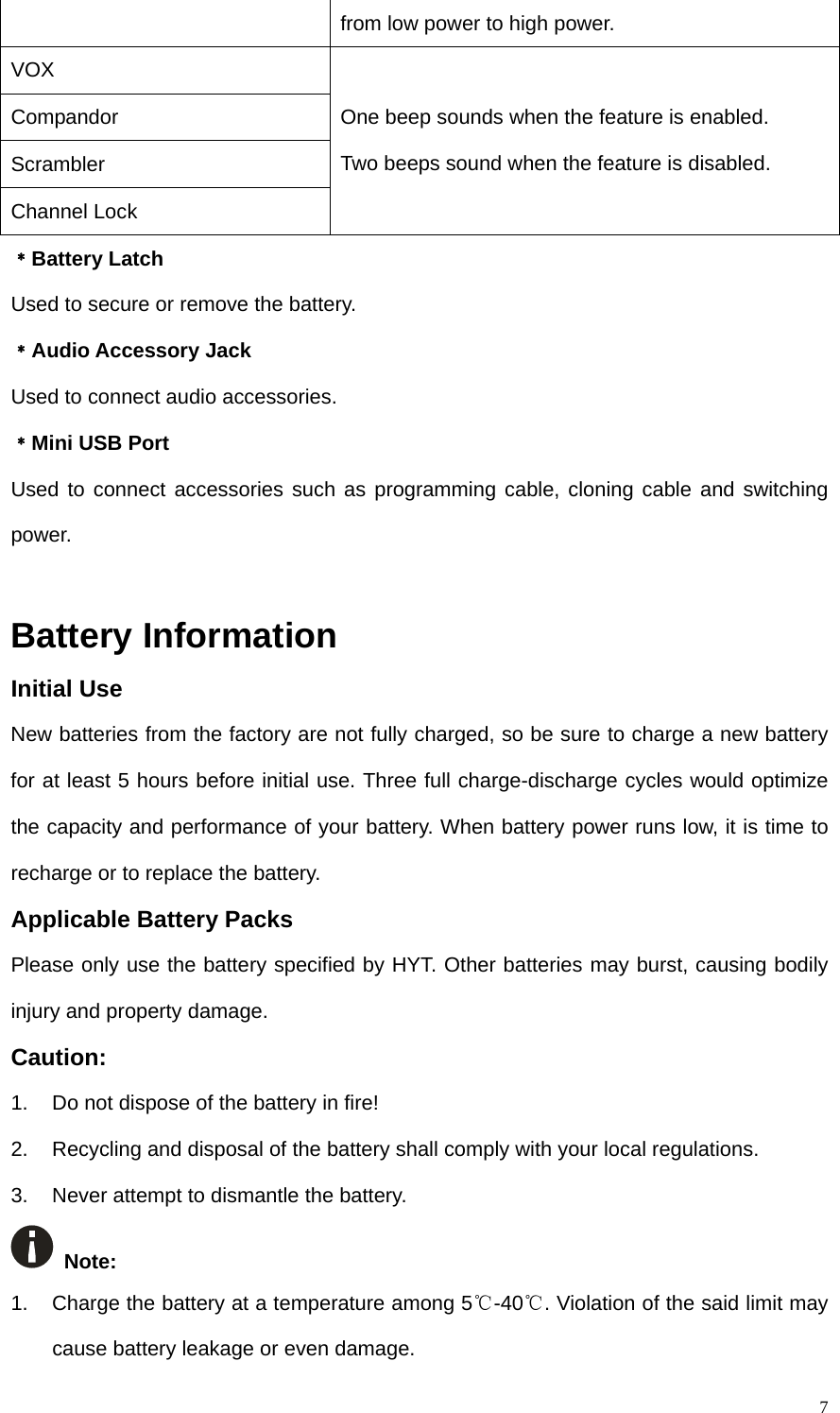
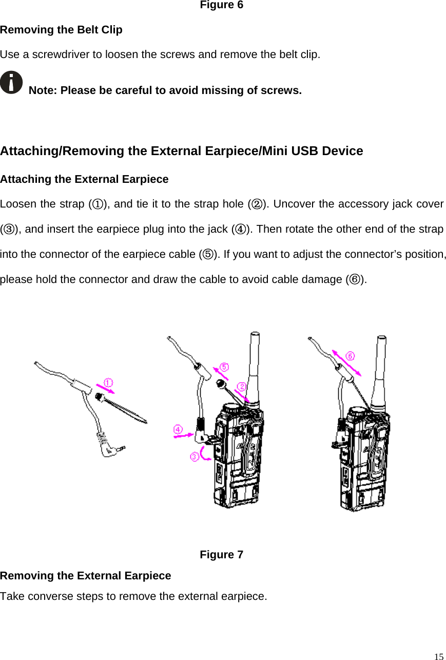
![5Radio Overview (1) Strap Hole (2) Power On/Off Key (3) Antenna (4) Volume Control Key [+] (5) PTT (Push-to-Talk) Key (6) Volume Control Key [-] (7) Programmable Function Key (8) Microphone (9) Channel Selector Knob (10) Channel Mark (11) Status Indicator (12) HYT Logo (13) Charge Indicator (14) Speaker (15) Accessory Cover (16) Model Label (17) Audio Accessory Jack (18) MINI USB Port (19) Screw for Belt Clip (20) Battery (21) Belt Clip (22) Charging Piece (23) Battery Latch ﹡PTT (Push-to-Talk) Key Press and hold down the PTT key to transmit, and release it to receive. ﹡Programmable Function Key The side keys can be programmed with long/short press functions by your dealer.](https://usermanual.wiki/HYT-Science-and-Technology-Co/TC-310U2/User-Guide-1136123-Page-8.png)
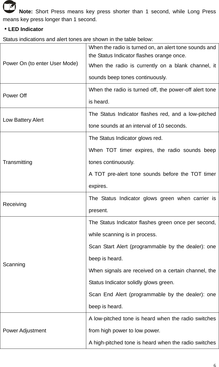
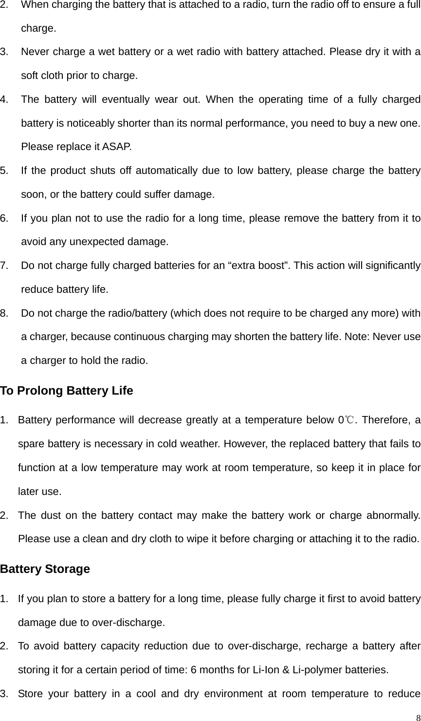
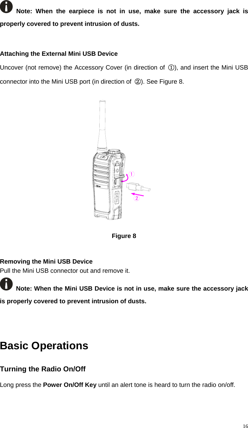
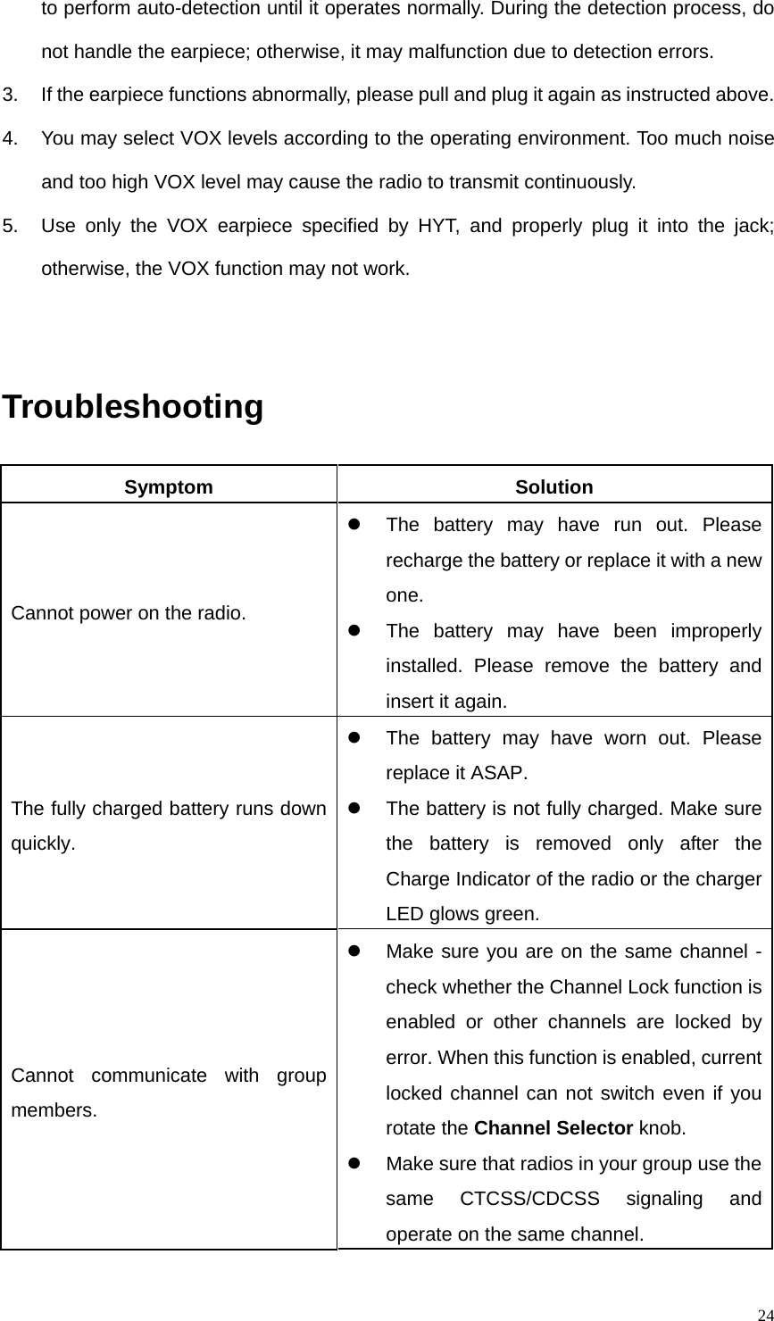
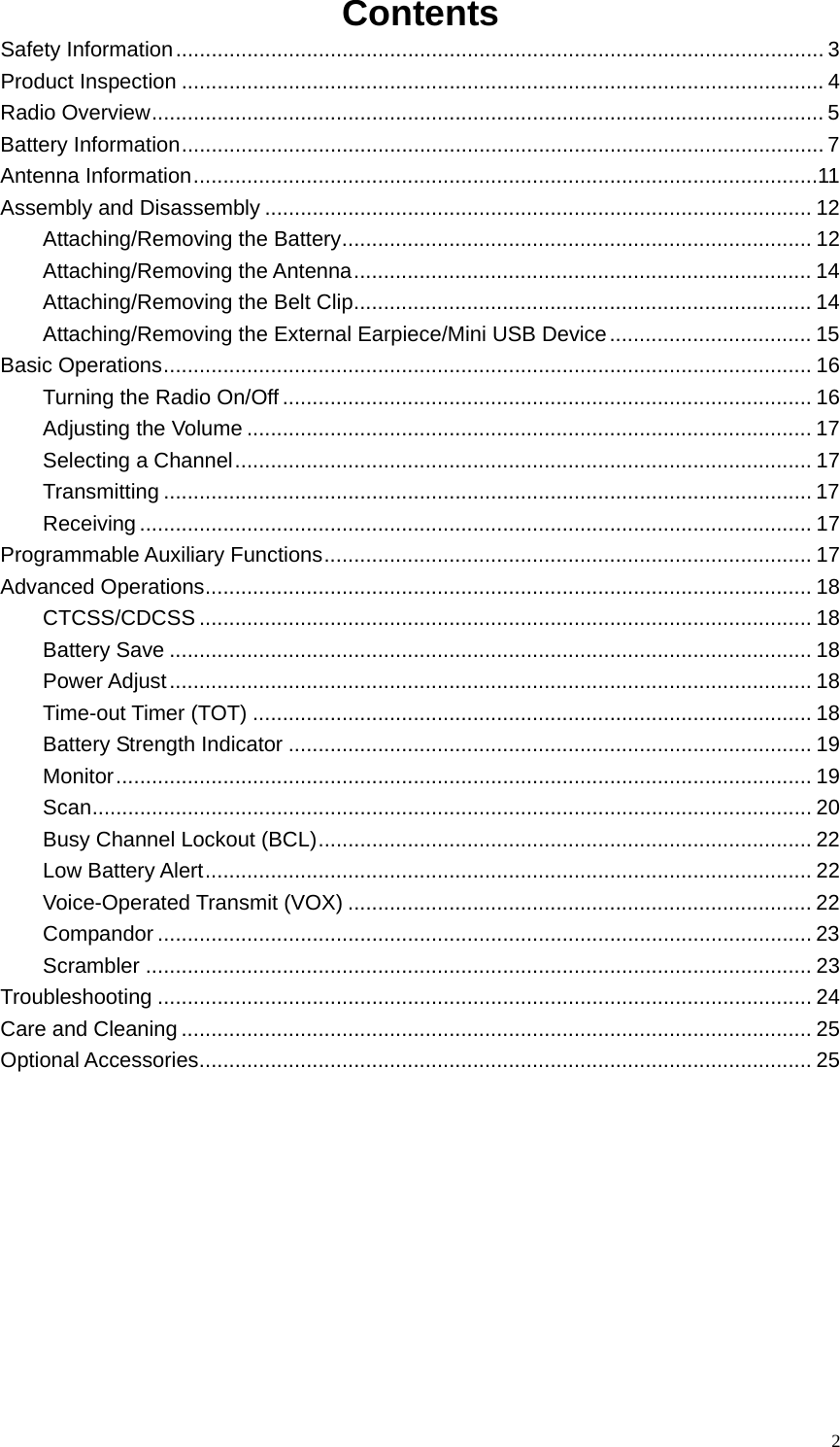
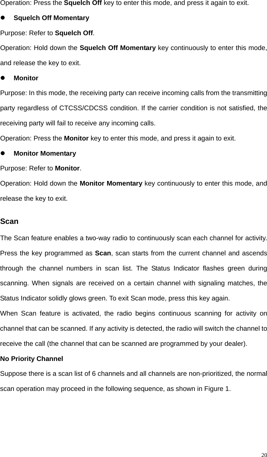
![17Adjusting the Volume Press [+] to increase or [-] to decrease the volume level. During volume adjustment, the radio will sound alert tones at your selected volume level. Selecting a Channel Rotate the Channel Selector Knob to align the channel numbers. Transmitting Press and hold down the PTT key, and speak into the microphone at your normal voice level. Hold the radio about 2.5 to 5 centimeters away from your mouth. Receiving Release the PTT key to receive. Programmable Auxiliary Functions Your dealer can program the following auxiliary functions to the programmable keys (with long/short press). z None z Power Adjustment z Monitor z Monitor Momentary z Scanning z Scrambler z Voice-operated Transmit (VOX) z Compandor z Squelch Off z Squelch Off Momentary z Battery Strength z Channel Lockout (When this function is enabled, the current locked channel can not](https://usermanual.wiki/HYT-Science-and-Technology-Co/TC-310U2/User-Guide-1136123-Page-20.png)
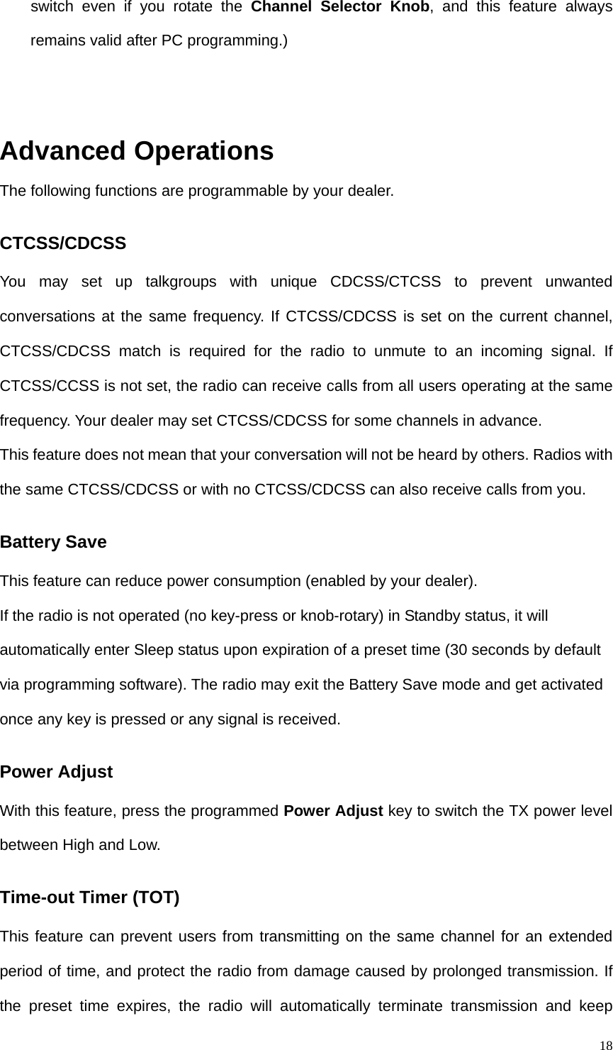
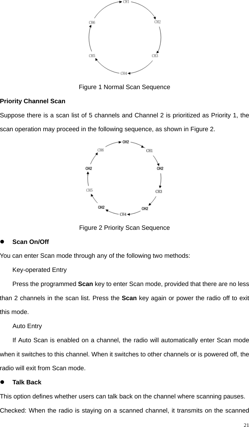
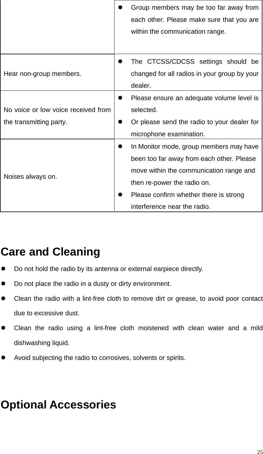
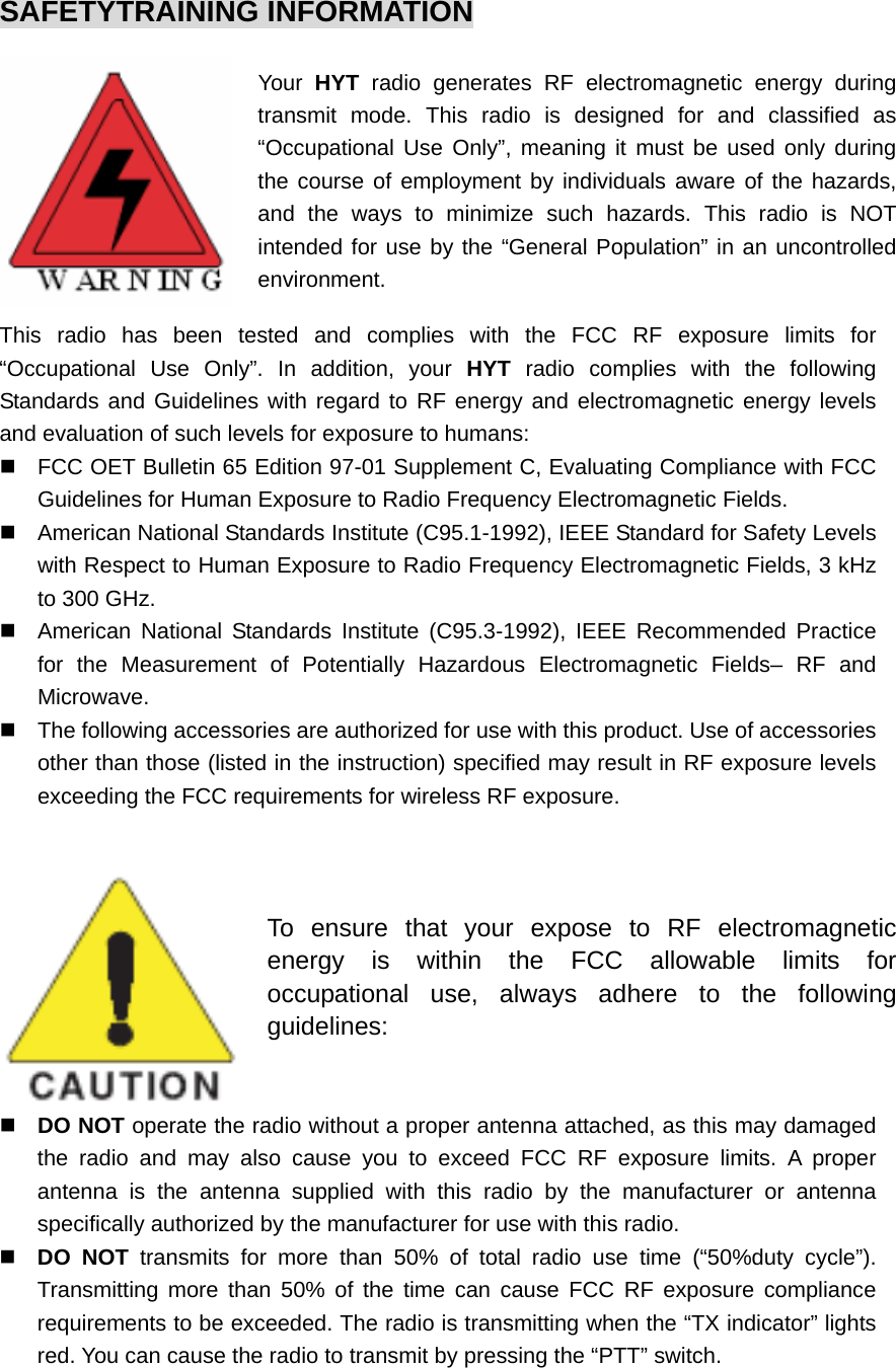
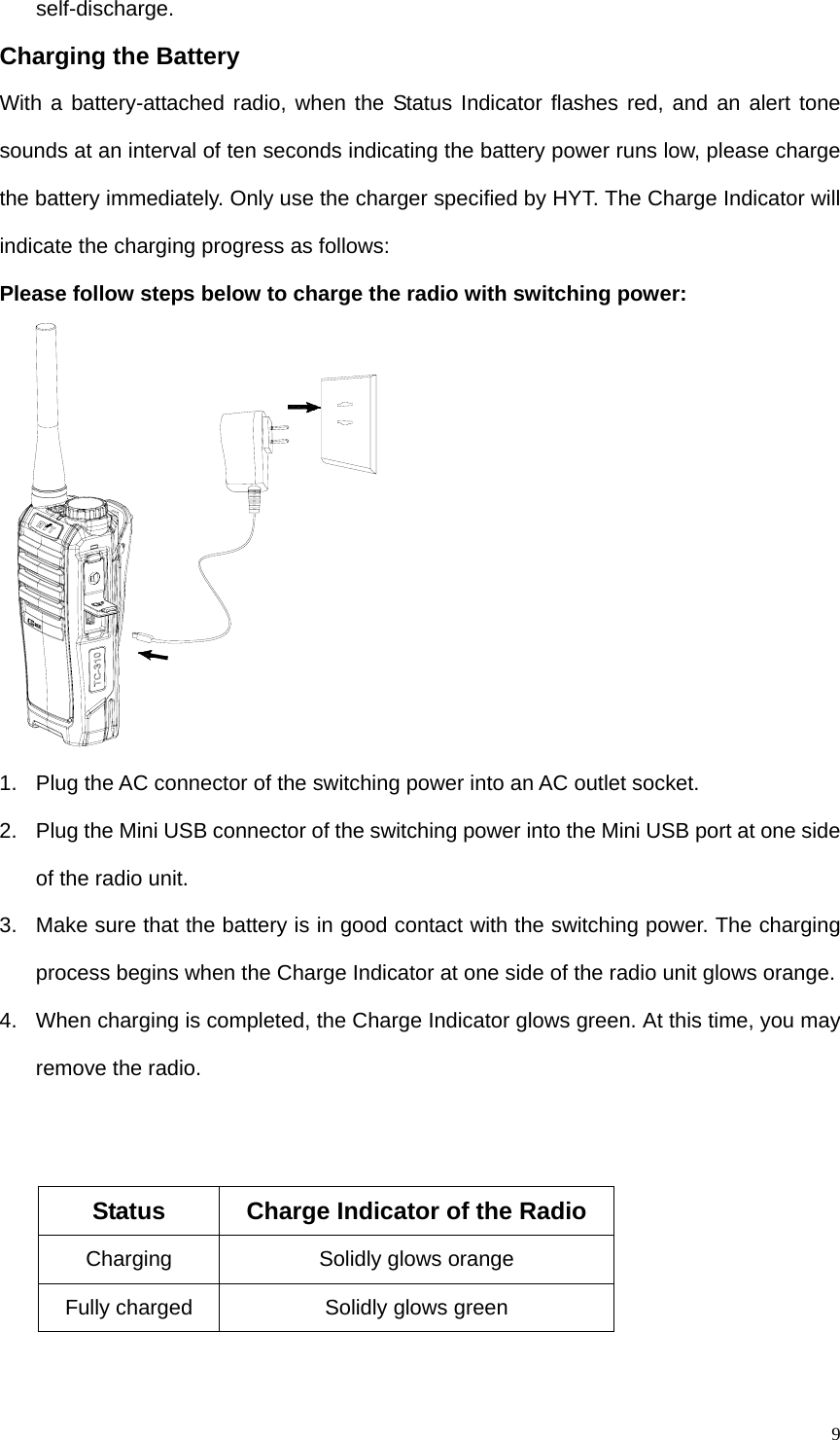
![22channel; when the radio is not staying on a scanned channel, it transmits on a preset channel. Unchecked: The radio transmits on the preset channel. z Priority Scan This function enables users to scan the most frequently used channel so that messages will not be missed. The priority channels are programmed by your dealer via programming software. Please contact your local dealer for more information. Note: Even though the radio stays on a non-priority channel, activities on the priority channel are still under detection. The radio will switch to the priority channel once any activity is detected. z Available Keys in Scan Mode PTT key, Volume Control key [+]/[-], Squelch Off, Squelch Off Momentary, Monitor and Monitor Momentary. Busy Channel Lockout (BCL) This function can help avoid interference between radios operating on the same channel. When the channel is already in use, the radio will sound a continuous warning tone and return to Receive mode upon PTT press. To cancel the tone, release the PTT key. Low Battery Alert When battery power runs low, the Status Indicator flashes red and a low-pitched tone will sound at an interval of ten seconds to remind users to replace the battery or charge the battery. Voice-Operated Transmit (VOX) With the dedicated VOX earpiece, you can enjoy hands-free communication. After this function is enabled, the radio will automatically begin transmitting when you speak, and terminate transmitting when you stop talking, with no need of PTT press. Operation Steps: 1. Push the PTT/VOX switch on the earpiece to VOX.](https://usermanual.wiki/HYT-Science-and-Technology-Co/TC-310U2/User-Guide-1136123-Page-25.png)