HYT Science and Technology Co TC-700U Two Way Radio User Manual THANK YOU
Shenzhen HYT Science &Technology; Co Ltd Two Way Radio THANK YOU
Users Manual
THANK YOU!
We are grateful for your purchase of HYT product. We believe this easy–to-use
radio will provide you with clear and reliable communications in high efficiency.
This HYT portable two-way radio is a precision device. Treat it with care, and
you will enjoy years of reliable operation.
MODELS COVERED IN THIS MANUAL
TC700 VHF Two-way Radio
TC700 UHF Two-way Radio
1
Contents
User Safety, Training, and General Information
Compliance with RF Energy Exposure Standards
FCC Compliance
Precautions
Product Inspection
Battery Information
Accessory Installation
Attaching/Removing the Battery
Attaching/Removing the Antenna
Attaching/Removing the Belt Clip
Attaching Remote Earphone/Microphone
Getting Acquainted
Programmable Auxiliary Functions
Basic Operation
Advanced Operations
Auto Dial
Emergency
Lone Worker
Man Down (optional)
Monitor/Squelch Off
Scan
SQL Check & Adjust
Voice Encryption
Talk Around
Power Check & Adjust
Whisper
VOX
Battery Power Indicator
Rental Time Indicator
2
Communication Range Alarm
Background Operations
Time-out Timer (TOT)
Busy Channel Lockout (BCL) and Busy Tone Lockout (BTL)
Battery Save
Low Battery Alert
CTCSS/DCS
DTMF
2-Tone/5-Tone
Signaling Control
PTT ID
Troubleshooting Guide
Care and Cleaning
Optional Accessories
Frequency Chart
3
User Safety, Training, and General Information
READ THIS IMPORTANT INFORMATION ON SAFE AND EFFICIENT OPERATION
BEFORE USING YOUR HYT PORTABLE TWO-WAY RADIO.
Compliance with RF Energy Exposure Standards
Your HYT two-way radio is designed and tested to comply with a number of national and
international standards and guidelines (listed below) regarding human exposure to radio
frequency electromagnetic energy. This radio complies with the IEEE (FCC) and ICNIRP
exposure limits for occupational/controlled RF exposure environment at duty cycles of up
to 50% talk-50% listen and should be used for occupational use only. In terms of
measuring RF energy for compliance with the FCC exposure guidelines, your radio
radiates measurable RF energy only while it is transmitting (during talking), not when it is
receiving (listening) or in standby mode.
Note: The approved batteries supplied with this radio are rated for a 5-5-90 duty cycle (5%
talk-5% listen-90% standby), even though this radio complies with the FCC
occupational RF exposure limits at duty cycles of up to 50% talk.
SAR measured values of body-worn is 3.52 mW/g and face-held is 2.29 mW/g.
Your HYT two-way radio complies with the following of RF energy exposure
standards and guidelines:
z United States Federal Communications Commission, Code of Federal Regulations;
47CFR part 2 sub-part J
z American National Standards Institute (ANSI)/Institute of Electrical and Electronic
Engineers (IEEE) C95. 1-1992
z Institute of Electrical and Electronic Engineers (IEEE) C95. 1-1999 Edition
International Commission on Non-Ionizing Radiation Protection (ICNIRP) 1998
Operational Instructions and Training Guidelines
To ensure optimal performance and compliance with the occupational/controlled
environment RF energy exposure limits in the above standards and guidelines, users
should transmit no more than 50% of the time and always adhere to the following
procedures:
4

Transmit and Receive
To transmit (talk), push the Push-To-Talk (PTT) button; to receive, release the PTT button.
Hand-held radio operation
Hold the radio in a vertical position with the microphone one to two inches (2.5 to 5 cm)
away from the lips.
Body-worn operation
z Always place the radio in an HYT approved clip, holder, holster, case, or body
harness for this product. Use of non-HYT-approved accessories may exceed FCC
RF exposure guidelines.
Antennas & Batteries
Use only HYT approved, supplied antenna or HYT approved replacement antenna.
Unauthorized antennas, modifications, or attachments could damage the radio and may
violate FCC regulations.
z Use only HYT approved, supplied batteries or HYT approved replacement batteries.
Use of non- HYT -approved batteries may exceed FCC RF exposure guidelines.
Approved Accessories
For a list of HYT approved accessories, see the accessories page of this user manual or
visit the following website which lists approved accessories: http://www.HYT.com.cn
FCC Compliance
This equipment has been tested and found to comply with the limits for a Class B digital
device, pursuant to FCC Rules. These limits are designed to provide reasonable
protection against harmful interference in a residential installation. This equipment
generates, uses and can radiate radio frequency energy and, if not installed and used in
accordance with the instructions, may cause harmful interference to radio
communications. However, there is no guarantee that interference will not occur in a
particular installation. If this equipment does cause harmful interference to radio or
television reception, which can be determined by turning the equipment off and on, the
user is encouraged to try to correct the interference by one or more of the following
measures:
Reorient or relocate the receiving antenna.
Increase the separation between the equipment and receiver.
Connect the equipment into an outlet on a circuit different from that to which the
5
receiver is connected.
Consult the dealer or an experienced radio/TV technician for help.
FCC Licensing Requirements
Your radio must be properly licensed Federal Communications Commission prior to use.
Your HYT Wireless dealer can assist you in meeting these requirements. Your dealer will
program each radio with your authorized frequencies, signaling codes, etc., and will be
there to meet your communications needs as your system expands.
Precautions
• Only qualified technicians are allowed to maintain this product.
• Do not use the radio or charge a battery in explosive areas such as coal gas, dust,
steam, etc.
• Switch OFF the radio while refueling or parking at gas station.
• Do not modify or adjust this radio without permission.
• Do not expose the radio to direct sunlight over a long time, nor place it close to heating
source.
• Do not place the radio in excessively dusty, humid areas, nor on unstable surfaces.
Safety: It is important that the operator is aware of and understands hazards common to
the operation of any radio.
6

Product Inspection
Please carefully unpack the radio. Before use, it is recommended that you inspect the
product as follows.
First check the shipping carton for any signs of damage. Confirm the supplied product
against the packing slip to assure accuracy. If any items are missing or have been
damaged during shipment, please file a claim to the carrier immediately.
Supplied Accessories
Item Qty. (PCS)
Antenna * 1
Battery 1
Desktop Charger 1
Power Adapter 1
Strap 1
Belt Clip 1
Screw (belt clip) 2
Owner’s Manual 1
Warranty Card 1
Declaration of Conformity 1
*Note: Frequency is marked on the color circle of the antenna. Red circle indicates UHF
and green indicates VHF. If frequency is not marked on the color circle, please refer to the
label on the main unit for details.
7
Battery Information
Battery Charging Information
The battery is not charged at the factory. Batteries must be fully charged before initial use
or if they have not been used for some period of time. The battery capacity will be
optimum only after being charged/discharged for two or three times. When the battery
power is low, it either needs to be charged or replaced with a new one.
Applicable Battery Packs
Charge only the battery packs listed below. Other types of batteries may burst, causing
personal injury.
BL-700A (7.2V 1700mAh)
BL-700B (7.2V 1700mAh)
Notes:
1. Do not short out the battery terminals or dispose of the battery by fire.
2. Never attempt to disassemble the battery.
3. Charge the battery in 5 to 40℃ temperature, otherwise the battery can’t be fully
charged.
4. Turn off the radio before charging. Using the radio while charging its battery will
interfere with correct charging.
5. Do not pull/plug the adaptor and the battery in the charging process to avoid interfering
with the charging phase.
6. When the battery operating time decreases even though it is fully and correctly charged,
that means the battery life is over, please replace it with a new one.
7. Do not recharge the optional Ni-MH battery if it is already fully charged, otherwise, the
battery life will be shortened or damage may be caused.
WARNING: Conductive metals including jewelry, key, decorating lace may result in short
circuit and generate a large quantity of heat when coming into contact with battery
electrodes. To avoid damage to articles or human injury, treat any battery with care,
especially when placing it into pocket, wallet or other mental containers.
8
Charging the Battery
When radio LED flashes red and three Beeps sound within 30 seconds after the battery is
installed, that means battery power is low. Please charge the battery.
You are recommended to use HYT-approved, supplied charger; Charger LED will indicate
the charging status.
LED Status
Red LED glows Charging
Green LED glows Done
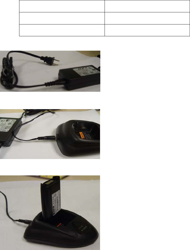
1. Plug the power cord into the adapter. (See Fig. 1)
Fig. 1
2. Plug the DC socket of adapter into the DC jack on back of the charger. (See Fig. 2)
Fig. 2
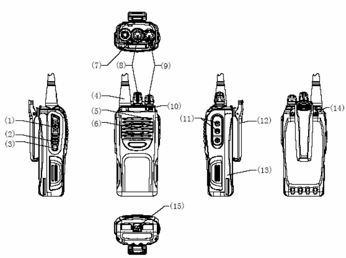
3. Insert the battery or the radio with battery into the charger cup. (See Fig. 3)
Fig. 3
4. Plug the AC socket of adapter into an AC outlet. (See Fig. 4)
9
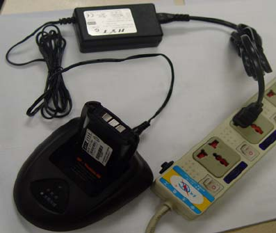
Fig. 4
5. Make sure the battery is well connected with the charger connectors; when charging
starts, the red LED glows.
5. The green LED glows when the battery is fully charged in about 3 hours, please remove
the battery or the radio with battery from the charger.
*Notes:
*Charger LED may flash if you connect the charger to power source before inserting the
battery.
*After removing the battery from charger, do not insert the battery or another one into
charger until charger LED glows green.
* When battery and charger connector are well connected, charger LED will solidly glow
red in charging mode and flashes when the battery is damaged or ambient temperature
is over high or over low.
10
Accessory Installation
Attaching the Battery
1. Push the battery along the guide on back of the radio until the battery latch at the
bottom of the radio locks.
Removing the Battery
1. Turn off the radio.
2. Pull back the battery latch.
3. Slide the battery away from the radio.
Attaching the Antenna
1. Screw the antenna into the connector on the top of radio by holding the antenna at its
base.
2. Turn the antenna clockwise to fasten it.
Removing the Antenna
1. Turn the antenna counter-clockwise until you can remove it.
Attaching the Belt Clip
1. Align the screw eyelets of belt clip holder with those of radio chassis.
2. Use the supplied screws to lock it.
Removing the Battery Clip
1. Loosen the screw to remove the belt clip.
Attaching Remote Earphone/Microphone
1. Unclose the cover of the earphone/microphone jack (no need to remove it);
2. Insert the earphone/microphone plug into the jack.
Note: The radio is not fully water resistant while using remote earphone/microphone.
11
Getting Acquainted
(1) PTT Key
●To transmit, hold down the PTT key and speak into the microphone; Release it to
receive.
(2) SK1 (Side Key 1)
●Programmable key
(3) SK2 (Side Key 2)
●Programmable key
(4) Antenna
(5) Microphone
(6) Speaker
(7) TK (Top Key)
●Programmable key
(8) Channel Selector Knob
●Rotate the knob to select channel 1-16.
(9) Power/Volume Control Knob
●Rotate the knob clockwise until a “click” sounds to turn on the radio; Rotate it
counter clockwise to turn off the radio. When the radio is on, turn the knob to adjust
12

the volume.
(10) LED Indicator
Radio status is indicated by LED state/color or alert tone.
Indication LED State/Color Alert Tone
Power on Flash orange twice
Source radio during
cloning Solidly glow red
User Wired Clone Mode
Target radio during
cloning Solidly glow green
Power on Flash orange three times
Source radio during
cloning Solidly glow red
Special Wired Clone Mode
Target radio during
cloning Solidly glow green
Power on Flash orange once
Source radio during
cloning Solidly glow red
Wireless Clone Mode
Target radio during
cloning Solidly glow green
Power on Flash red twice
Switch to wideband Flash red once
Switch to F1 Flash green once
Manual Adjust Mode
Select adjustment
item group
Group 1: flash orange
once
Group 2: flash orange
twice
All Reset Mode Flash green twice
Power on in User Mode Flash green once
Low Battery Alert Solidly glow red three Beeps
every 30s
Transmit Glow red
Receive Glow green
Scan Flash red once every
second
Read Glow red
Read/Write Write Glow green
Transmitting Glow red DTMF/PTT ID/2Tone
/5Tone Transmit Done Glow orange
2Tone/5Tone Decode Flash orange when
decoding is completed
1W one Beep High/Middle/Low Power
2.5W two Beeps
13

4W three Beeps
Enter one Beep
Programmable Key Exit two Beeps
(11) Speaker/Microphone Jack
(12) Belt Clip
(13) Battery
(14) Screws (belt clip)
(15) Battery Latch
14
Programmable Auxiliary Functions
Your dealer can program each of the TK, SK1, SK2 keys with one of the following auxiliary
functions. Please refer to their descriptions in “Advanced Operation”.
● None (No Function)
● Call1/Call2
● Emergency
● Emergency Cancel
● Lone Worker
● Man Down (optional)
● Monitor Toggle
● Monitor Momentary
● Nuisance Temporary Delete
● Nuisance Delete
● SQL Check & Adjust
● Scan
● Scrambler
● Scrambler with Back Up
● Squelch Off
● Squelch Off Momentary
● Talk Around
● Power Check & Adjust
● Whisper
● VOX
● Battery Power Indicator
● Rental Time Indicator
● Communication Range Alarm
15
Basic Operation
1. Turn On the Radio: Rotate the Power/Volume Control knob clockwise until green LED
flashes one time.
● A BEEP sounds if alert tone is set your dealer.
2. Monitor: press the preprogrammed MONI key or SQ OFF key to hear
background noise, then turn the Power/Volume Control knob to adjust the volume.
3. Select Channel: Rotate Channel Selector Knob to select your desired channel; the
radio will report the current channel number when one is selected.
4. Transmit: Press and hold PTT, speak into the microphone with normal voice.
● Keep microphone about 3 to 4cm away from your lips.
5. Receive: Release PTT, the radio returns to receive mode.
16

Advanced Operations
The following functions are programmable by your dealer, as described above.
Auto Dial
Press the preprogrammed Call1/Call2 key to transmit the stored DTMF code, 2-tone
/5-tone code.
Emergency
Program the programmable key (TK) with emergency feature. When activated, the
emergency feature enables the radio to emit emergency alarm or send ENI (Emergency
Number Identity) / background tone to companions or system (as selected by user via
programming software).
① ②
Emergency Press and hold Briefly press
Emergency Cancel Briefly press Press and hold
Lone Worker
The preprogrammed Lone Worker key is pressed to ensure user’s safety when they work
alone. It includes two modes:
■Auto Check: In lone worker mode, the radio will sound an alert tone at the preset time.
User must press a key to reset the timer (the user is safe), otherwise, the radio will
automatically enter emergency mode.
■Safety Check: When receiving a safety check signal, the radio will emit an alert tone.
Press any key to reset the radio, indicating the user is safe; otherwise, the radio will
automatically enter emergency mode
Man Down(optional)
In man down mode, the radio will automatically enter emergency alert mode if it is
horizontally or inversely positioned after the preset time elapses. Place the radio in the
vertical position to disable the emergency alert feature.
17
Monitor/Squelch Off
● Monitor Toggle
Press the preprogrammed Monitor Toggle key to enable the signaling squelch feature;
press it again to exit.
● Monitor Momentary
Press and hold the Monitor Momentary key to enable the signaling squelch feature;
release it to exit.
● Squelch Off
Press the preprogrammed Squelch Off key to activate the noise squelch feature; press
it again to exit.
● Squelch Off Momentary
Press and hold the Squelch Off Momentary key to activate the noise squelch feature;
release it to exit.
Scan
Press the preprogrammed Scan key, scan starts from the current channel and goes
through the scan list. Red LED flashes in scan mode and solidly glows when a signal is
received on a channel and signaling matches. Press the key again to exit.
● Nuisance Temporary Delete
When scan stops on a channel, press the preprogrammed Nuisance Temporary
Delete key to temporarily remove the channel from the scan list.
■ You cannot delete the priority channel, if one has been set.
■ You cannot delete a channel if there will be less than 2 channels available for
scanning.
■ Exit from scan mode or turn on the radio again, the deleted channel will return
to the scan list.
● Nuisance Delete
Press the preprogrammed Nuisance Delete key to permanently remove the channel
from the scan list. The deleted channel can’t return to the scan list even though the
18
radio exits from Scan mode or restarts.
■ You cannot delete the priority channel, if one has been set.
■ You cannot delete a channel if there will be less than 2 channels available for
scanning.
SQL Check & Adjust
Program one of the programmable keys with this feature;
Press and hold the preprogrammed key to hear the squelch level of the current channel.
Briefly press the key to adjust the SQL. Squelch will be increased by one level and setting
is saved each time when you press the key.
Voice Encryption
The voice encryption feature includes scrambler and scrambler with back up.
Usually both the calling and called radios activate the scrambler feature to prevent other
parties using the same frequency from wiretapping.
■ Scrambler
Press the preprogrammed Scrambler key, the radio scrambles your voice so
that anybody listening to your conversation will not be able to understand what
you are saying. The information is not stored when the radio is powered on
again.
■ Scrambler with Back Up
Press the preprogrammed Scrambler with Back Up key to activate the
scrambling feature. The information is stored when the radio is powered on
again.
Talk Around
Press the preprogrammed Talk Around key, the radio will transmit on the RX frequency.
Power Check & Adjust
Program one of the programmable keys with this feature;
19
Press and hold the preprogrammed key, Beep tone corresponds to power level, a Beep
indicates Low power; two Beeps indicate Middle power and three Beeps indicate High
power.
Briefly press the key to adjust the power level; Power will be increased by one level and
setting is saved each time when you press the key.
Whisper
Press the preprogrammed Whisper key, you would be clearly heard even if you speak with
low voice.
Press it again to exit.
VOX
Press the preprogrammed VOX key, the user can transmit without holding down the PTT
key. This feature can only be used with required audio accessory.
Battery Power Indicator
Press the preprogrammed Battery Power Indicator key, the battery power will be indicated
by audible indicating tone (“1”, “2”, “3”, “4”).
Rental Time Indicator
In rental mode, the radio can only be used for a preset period of time. Press the
preprogrammed Rental Time Indicator key, the radio will report the remaining time the
user is allowed to use the radio until the preset rental time elapses.
Communication Range Alarm
Audible alert will sound when your radio is out of communication range.
20
Background Operations
Time-Out-Timer (TOT)
Time-Out-Timer is used to prevent someone from using the same channel for a long time.
If the transmission exceeds the time preset by your dealer (default is 1 minute),
transmission will stop and an alert tone will sound. To stop the alert tone, release the PTT
key. Press the PTT key again to resume transmitting.
Your dealer can program a warning function to alert you before the TOT elapses.
Busy Channel Lockout (BCL) and Busy Tone Lockout (BTL)
When activated, the BCL and BTL feature will prevent you from talking on a channel that is
already in use. Press PTT while the channel is in use, the radio will generate an alert tone
and return to receive mode.
Carrier: If the selected channel is set by your dealer as “busy channel lockout” and is
being used by other users, press PTT, the radio will emit a Beep and will not
transmit signals.
CTCSS/DCS: If CTCSS/DCS is set on the selected channel that is programmed by your
dealer as “busy channel lockout” and is being used by other users, press
PTT, the radio will emit a Beep and will not transmit signals.
Opt signaling: If 2-Tone/5-Tone/DTMF/HDC-2400 is programmed on the selected channel
which is set by your dealer as “busy channel lockout” and is being used by
other users, press PTT, the radio will emit a Beep and will not transmit
signals.
Battery Save
It’s enabled by your dealer to minimize the amount of power used.
When there is no activity on the channel and no operation (no key is being pressed, and
no switch is being turned) is performed for 12 seconds, Battery Save is automatically
turned on. When a signal is received or an operation is performed, Battery Save is
automatically turned off.
21
Low Battery Alert
Low Battery Alert alerts you to recharge or replace the battery. When the battery voltage
becomes low, radio LED will flash red and three Beeps sound within 30 seconds,
indicating to recharge or replace the battery with a new one.
CTCSS/DCS
When CTCSS/DCS is set, the squelch feature will be opened only when signals
containing the matching tone or code are received. Likewise, your signals will be received
only by parties using the same CTCSS/DCS signaling.
CTCSS/DCS may have been programmed on a channel to block unwanted calls from
other parties using the same channel.
If other parties transmit on the same channel with different tone or code, the squelch
feature will not open and you will not hear the call. This allows you to ignore (not hear)
these calls. Although it may seem like you have a private channel while using
CTCSS/DCS, other parties can still hear your calls if the same tone or code is set.
DTMF
DTMF feature is set On/Off by your dealer. When it is set on a channel, press the
Programmable key (Call 1, Call 2) to transmit DTMF code.
●LED glows red during transmission and goes out when transmission ends.
2-Tone/5-Tone
2-Tone/5-Tone feature is set On/Off by your dealer. When it is set on a channel, press the
Programmable key (Call 1, Call 2) to transmit 2-Tone/5-Tone signal.
When 2-Tone/5-Tone is set on a channel, the preset functions will only be activated when
the matching 2-Tone/5-Tone signals are received. Likewise, your signals will be received
only by parties using the same 2-Tone/5-Tone signals.
● Red LED glows during transmission; orange LED glows when the radio completes
the transmission and receives a confirmation signal indicating successful decode,
otherwise, the light goes out.
22
● LED glows green in decode mode, and flashes orange for a preset period of time
after successful decoding.
Signaling Control
CTCSS/DCS AND 2-Tone/5-Tone: If both signalings are employed, the squelch feature
is only opened when both match.
CTCSS/DCS OR 2-Tone/5-Tone: If both signalings are employed, the squelch feature
is opened when either matches.
PTT ID
Beginning / End of Transmission Identification signal (PTT ID) is used to
connect/disconnect the radio with repeaters and telephone systems.
Press PTT to transmit a Beginning of Transmission signal.
Release PTT to transmit an End of Transmission signal.
When both are set, briefly press PTT to transmit the ID signal.
23

Troubleshooting Guide
Trouble Solution
No power *Battery may be used up. Please recharge or replace the
battery.
*The battery may not be properly installed. Remove the battery
and attach it again.
Power doesn't last long even if fully
charged
*Battery life is over, please replace it with a new one.
Can't talk to or hear group members *Make sure you are using the same frequency and same
CTCSS as your group members.
*Your group members may be out of the communication range.
Other voice (non-group members)
are present on the channel
*Change CTCSS tone. Make sure your group members all
change to the same tone.
Care and Cleaning
* Do not carry your radio by the antenna or remote microphone;
* Wipe the battery contacts with a lint-free cloth to remove dirt, grease, or other material
that may prevent good electrical connection;
* When not in use, keep the accessory jacks covered with the protective caps;
* Clean the shell, controls and keys of your radio with neutral detergent and warm water
after a long period of usage. Avoid using strong chemicals.
24

Optional Accessories
Earset with boom microphone & in-line PTT EH-M2
Earset with in-line microphone & PTT EH-M3
Earbud with in-line microphone & PTT ES-M1
Remote speaker microphone
Antenna (VHF/UHF)
Frequency Chart
Model: ____________________
Serial Number: ________________
Channel Transmit Frequency Transmit CTCSS/CDCSS Receive Frequency
Receive
CTCSS/CDCSS
1
2
3
4
5
6
7
8
9
10
11
12
13
14
15
16
HYT endeavors to achieve the accuracy and completeness of this manual, but cannot
guarantee its accuracy at all times. All the above specifications and design are subject to
change by HYT without notice.
All the reproduction and translation of this manual without authorization of HYT is not allowed.
25