HYT Science and Technology Co TC-780MU1 TWO-WAY RADIO User Manual User s Manual
Shenzhen HYT Science &Technology; Co Ltd TWO-WAY RADIO User s Manual
UserManual.wiki
>
HYT Science and Technology Co
>
TC 780MU1 User Manual
USERS MANUAL
Navigation menu
Upload a User Manual
Namespaces
Wiki Guide
HTML
PDF
Info
Views
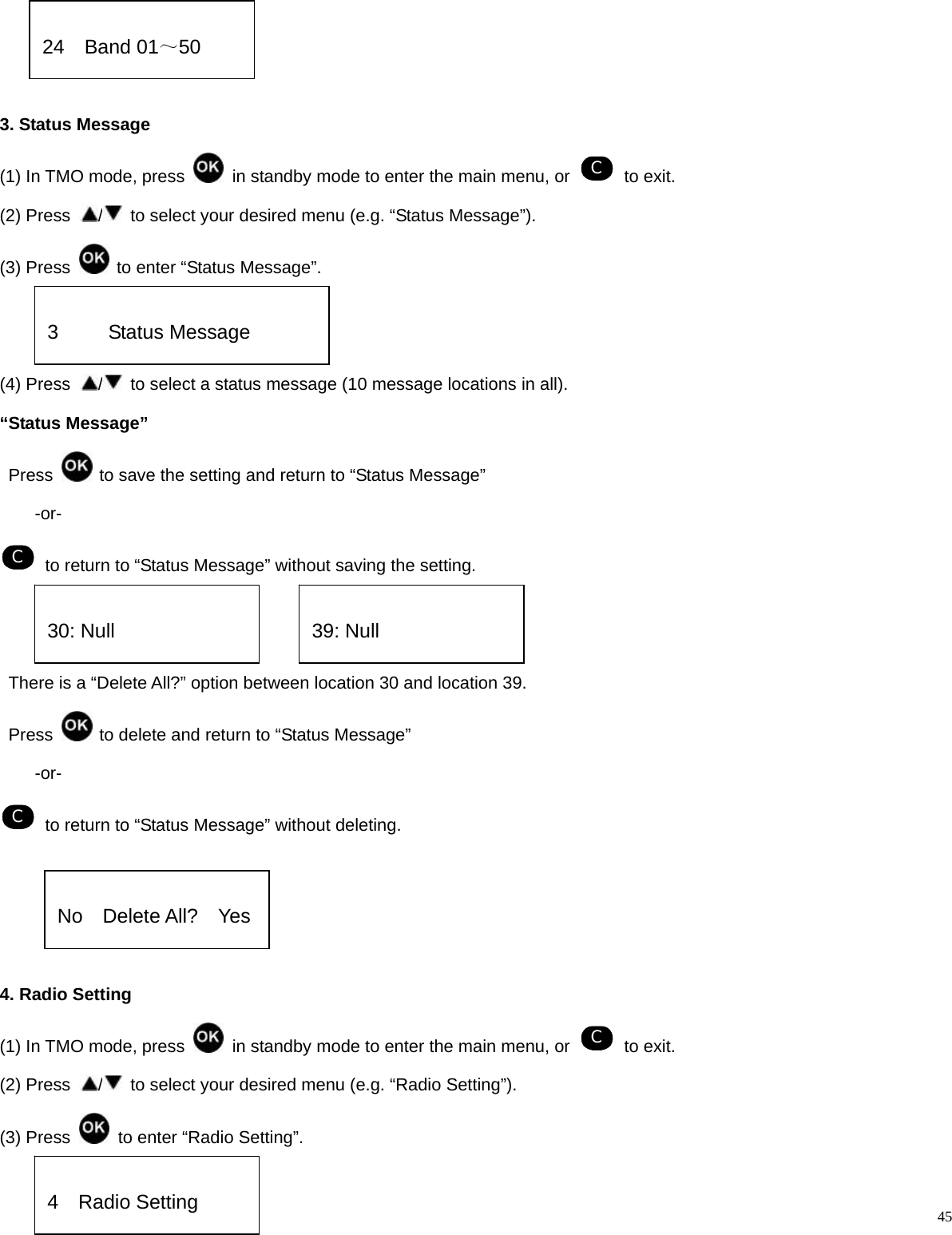
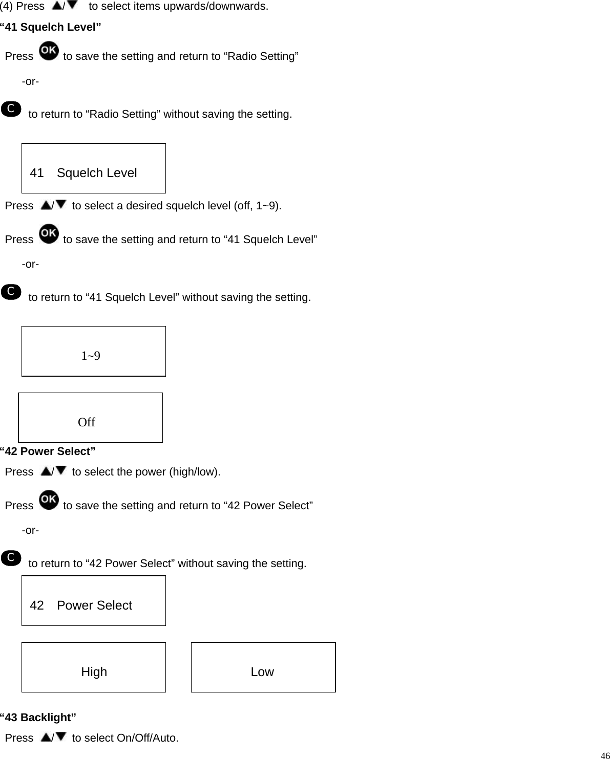
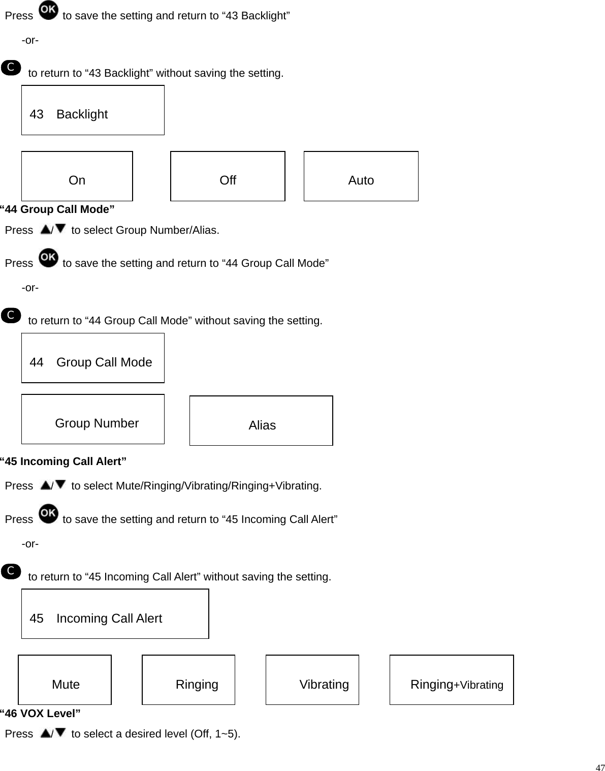
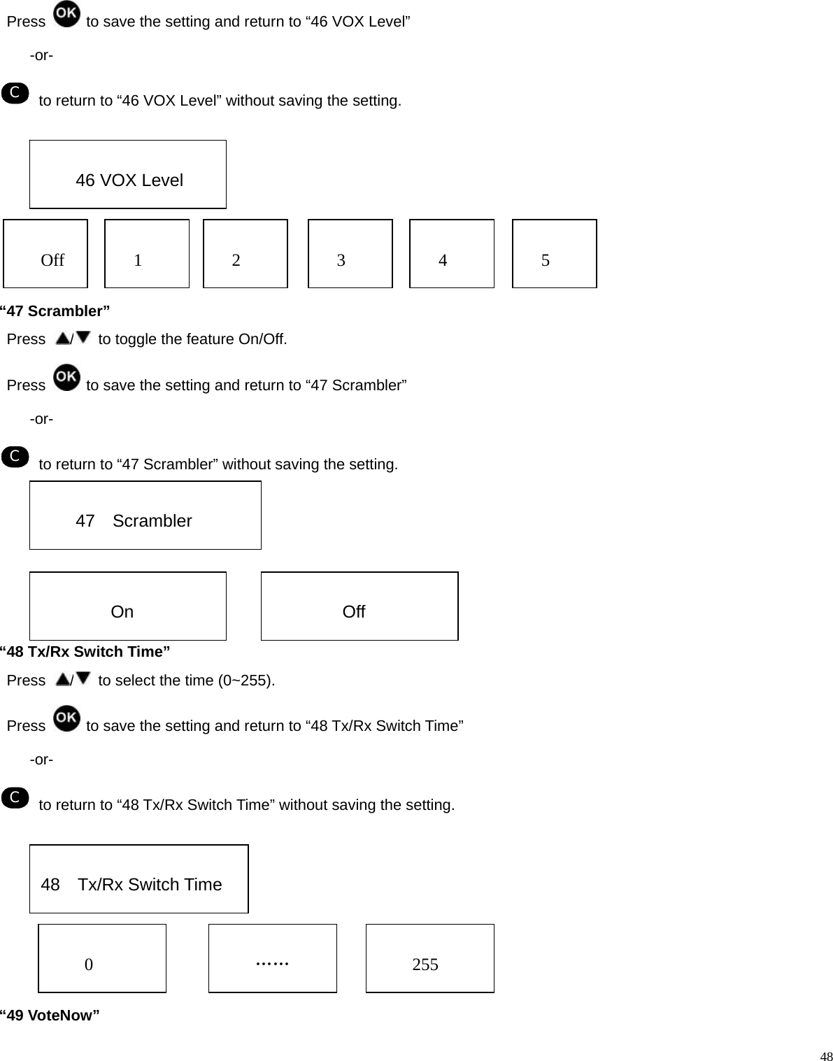
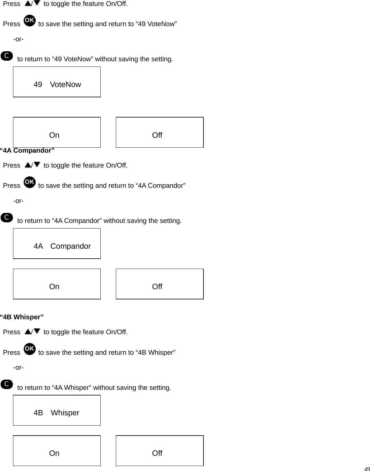
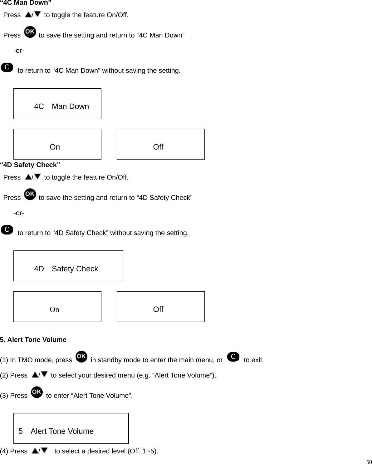
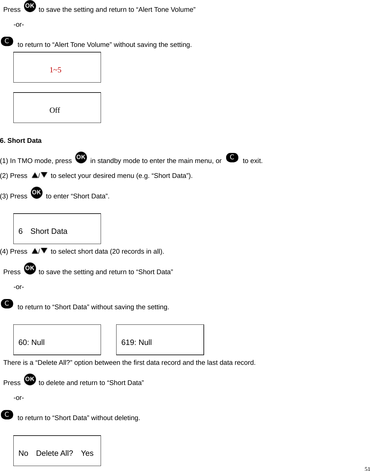
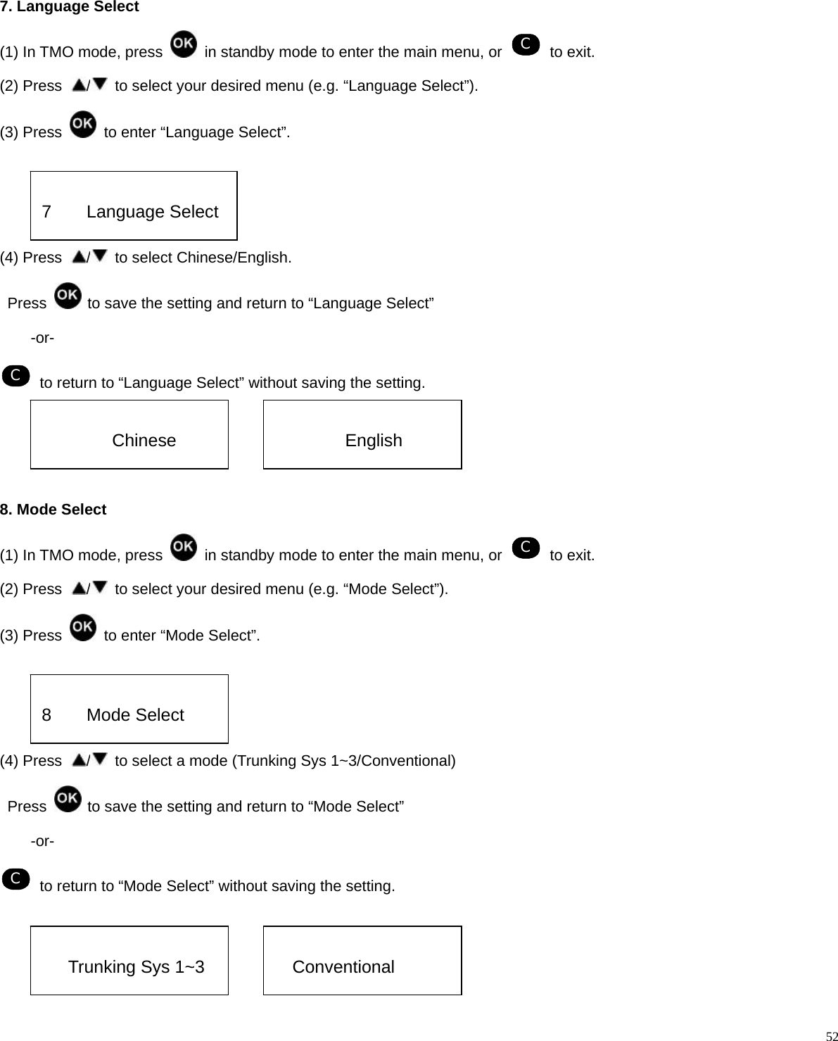
User Manual
Discussion / Help
Navigation