HYT Science and Technology Co TC-780MU2 Two-Way Radio User Manual User s Manual
Shenzhen HYT Science &Technology; Co Ltd Two-Way Radio User s Manual
Users Manual
PREFACE
Thank you for your purchase of the HYT TC-780M trunking radio. This radio is compliant with the GA176-1998 police use
standard and has passed the detect by the Ministry of Public Security. With powerful trunking functions, the radio supports
CPSX and MPT1343 numbering schemes, for domestic public security systems and other trunking users using standard
MPT1327 signalling. This easy-to-use radio will deliver your secure, instant and reliable communication at peak efficiency.
Please read this manual carefully before use. The information presented herein will help you to derive maximum
performance from your radio.
MODELS COVERED IN THIS MANUAL
TC-780M VHF Trunking Radio
TC-780M UHF Trunking Radio
1
Contents
Safety and General Information ................................................................................................................错误!未定义书签。
Product Inspection ..................................................................................................................................................................4
Radio Overview.......................................................................................................................................................................5
Battery Information..................................................................................................................................................................9
Antenna Information.............................................................................................................................................................. 11
Assembly and Disassembly .................................................................................................................................................. 11
Attaching the Battery...................................................................................................................................................... 11
Removing the Battery ....................................................................................................................................................12
Attaching the Antenna....................................................................................................................................................12
Removing the Antenna...................................................................................................................................................12
Attaching the Belt Clip....................................................................................................................................................13
Removing the Belt Clip ..................................................................................................................................................13
Removing the Accessory Cover.....................................................................................................................................14
Attaching the Earpiece/Microphone ...............................................................................................................................14
General Radio Operations ....................................................................................................................................................15
Programmable Auxiliary Functions........................................................................................................................................16
Trunking Mode ......................................................................................................................................................................18
Keypad Function............................................................................................................................................................18
Function Description ......................................................................................................................................................22
Manual Dial....................................................................................................................................................................30
Menu Operation.............................................................................................................................................................40
Conventional Mode...............................................................................................................................................................55
Advanced Operations ....................................................................................................................................................55
Background Operations .................................................................................................................................................59
Chinese/English Menu Operations ................................................................................................................................62
Appendix 1 LCD Icons ...................................................................................................................................................66
Appendix 2 Keypad Characters .....................................................................................................................................67
Troubleshooting ....................................................................................................................................................................67
Care and Cleaning................................................................................................................................................................67
Optional Accessories ............................................................................................................................................................68

2
SAFETYTRAINING INFORMATION
Your HYT radio generates RF electromagnetic energy during transmit mode. This radio is designed for and
classified as “Occupational Use Only”, meaning it must be used only during the course of employment by
individuals aware of the hazards, and the ways to minimize such hazards. This radio is NOT intended for use
by the “General Population” in an uncontrolled environment.
This radio has been tested and complies with the FCC RF exposure limits for “Occupational Use Only”. In addition, your
HYT radio complies with the following Standards and Guidelines with regard to RF energy and electromagnetic energy
levels and evaluation of such levels for exposure to humans:
FCC OET Bulletin 65 Edition 97-01 Supplement C, Evaluating Compliance with FCC Guidelines for Human Exposure to
Radio Frequency Electromagnetic Fields.
American National Standards Institute (C95.1-1992), IEEE Standard for Safety Levels with Respect to Human Exposure
to Radio Frequency Electromagnetic Fields, 3 kHz to 300 GHz.
American National Standards Institute (C95.3-1992), IEEE Recommended Practice for the Measurement of Potentially
Hazardous Electromagnetic Fields– RF and Microwave.
The following accessories are authorized for use with this product. Use of accessories other than those (listed in the
instruction) specified may result in RF exposure levels exceed the FCC requirements for wireless RF exposure.
To ensure that your expose to RF electromagnetic energy is within the FCC allowable limits for occupational
use, always adhere to the following guidelines:
DO NOT operate the radio without a proper antenna attached, as this may damaged the radio and may also cause you
to exceed FCC RF exposure limits. A proper antenna is the antenna supplied with this radio by the manufacturer or
antenna specifically authorized by the manufacturer for use with this radio.
DO NOT transmits for more than 50% of total radio use time (“50%duty cycle”). Transmitting more than 50% of the time
can cause FCC RF exposure compliance requirements to be exceeded. The radio is transmitting when the “TX indicator”
lights red. You can cause the radio to transmit by pressing the “PTT” switch.
ALWAYS keep the antenna at least 2.5 cm (1 inch) away from the body when transmitting and only use the HYT belt-clip
which is listed in instructions when attaching the radio to your belt, etc., to ensure FCC RF exposure compliance
requirements are not exceeded. To provide the recipients of your transmission the best sound quality, hold the antenna
at least 5 cm (2 inches) from your mouth, and slightly off to one side.
The information listed above provides the user with the information needed to make him or her aware of RF exposure,
and what to do to as-sure that this radio operates with the FCC RF exposure limits of this radio.
Electromagnetic Interference/Compatibility
During transmissions, your HYT radio generates RF energy that can possibly cause interference with other devices or
systems. To avoid such interference, turn off the radio in areas where signs are posted to do so. DO NOT operate the
transmitter in areas that are sensitive to electromagnetic radiation such as hospitals, aircraft, and blasting sites.
Occupational/Controlled Use
The radio transmitter is used in situations in which persons are exposed as consequence of their employment provided
those persons are fully aware of the potential for exposure and can exercise control over their exposure.

3
IMPORTANT
READ ALL INSTRUCTIONS carefully and completely before using the transceiver
SAVE THIS INSTRUCTION MANUAL- This instruction manual contains important operating instructions for the
Two-Way Radio
EXPLICIT DEFINITIONS
WORD DEFINITION
WARNING Personal injury, fire hazard or electric shock may occur.
CAUTION Equipment damage may occur.
NOTE If disregarded, inconvenience only. No risk of personal injury, fire or electric shock.
OPERATING NOTES
When transmitting with a portable radio, hold the radio in a vertical position with its microphone 5 to 10 cm (2 to 4 inches)
away from your mouth. Keep the antenna at least 2.5 cm (1 inch) from your head and body.
If you wear a portable two-way radio on your body, ensure that the antenna is at least 2.5 centimeters (1 inch) from your
body when transmitting.
PRECAUTIONS
WARNING! NEVER hold the transceiver so that the antenna is very close to, or touching exposed parts of the body,
especially the face or eyes, while transmitting. The transceiver will perform best if the microphone is 5 to 10 cm (2 to 4
inches) away from the lips and the transceiver is vertical.
WARNING! NEVER operate the transceiver with a headset or other audio accessories at high volume levels.
CAUTION! NEVER short the terminals of the battery pack.
NEVER connect the transceiver to a power source other than the Battery listed below Such a connection will ruin the
transceiver.
DO NOT push the PTT when not actually desiring to transmit.
AVOID using or placing the transceiver in direct sunlight or in areas with temperatures below –30°C (–22°F) or above
+60°C (+140°F).
DO NOT modify the transceiver for any reason.
MAKE SURE the flexible antenna and battery pack are securely attached to the transceiver, and that the antenna and
battery pack are dry before attachment. Exposing the inside of the transceiver to water will result in serious damage to
the transceiver.
BE CAREFUL! The series transceivers employ waterproof construction, which corresponds to IPX7 of the international
standard IEC 60529 (2001), 1 m depth for 30 minutes. However, once the transceiver has been dropped, waterproofing
cannot be guaranteed due to the fact that the transceiver may be cracked, or the waterproof seal damaged, etc.
The use of non-HYT battery packs/chargers may impair transceiver performance and invalidate the warranty.
FCC CAUTION:
Changes or modifications to this device, not expressly approved by HYT, could void your authority to operate this
transceiver under FCC regulations.
4
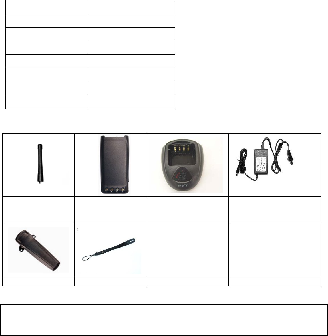
Product Inspection
Please unpack the package box carefully and check that all items shipped were received; report any missing or damaged
items to your dealer.
Accessories
Item Qty. (PCS)
Antenna 1
Belt Clip 1
Leather Strap 1
Li-Ion Battery 1
MCU Rapid-rate Charger 1
Switching Power 1
Owner’s Manual 1
Antenna Li-Ion Battery
(1700mAh)
MCU Rapid-rate Charger Switching Power (100-240V) (for
use with different power cords in
different countries and areas)
Belt Clip Leather Strap
Note: Frequency band is marked on the label of antenna, if not, identify the frequency band according to the color circle.
Please refer to the label on the radio unit for detailed frequency band information.
5
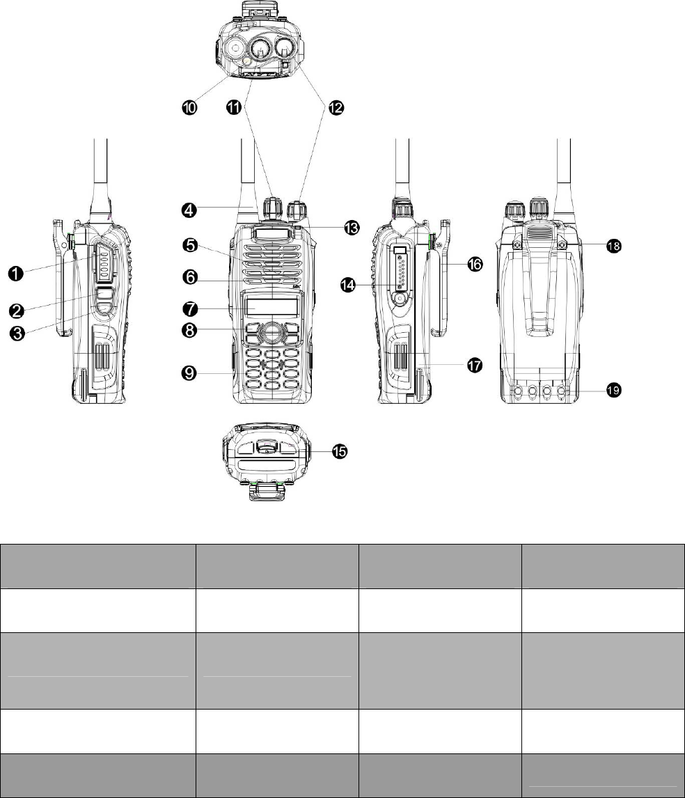
Radio Overview
○
1 PTT (Push-to-Talk) Key ○
2 SK1 (Side Key 1) ○
3 SK2 (Side Key 2) ○
4 Antenna
○
5 Microphone ○
6 Speaker ○
7 LCD Display ○
8 Function Keypad
○
9 Numeric Keypad ○
10 TK (Top Key) ○
11 Channel Selector
Knob
○
12 Radio On-Off
/Volume Control Knob
○
13 LED Indicator ○
14 Accessory Jack ○
15 Battery Latch ○
16 Belt Clip
○
17 Battery ○
18 Screw, Belt Clip ○
19 Charging Piece
﹡PTT (Push-to-Talk) Key
Press and hold down the PTT key to transmit; release it to receive.
6
﹡SK1 (Side Key 1)
Programmable function key.
﹡SK2 (Side Key 2)
Programmable function key.
﹡LCD Display
Used to display radio status information.
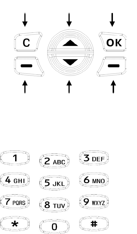
﹡Function Keypad
z Exit key
Use the Exit key to return to the previous menu.
z Up key
z Down key
z Menu/Select key
Used to enter the menu mode. When you are in the menu mode, this key is also used to make menu selections.
Exit Up Menu/Select
Call Back Down Redial
﹡Numeric Keypad
Used to enter information for programming the radio’s lists. When the radio operates in trunking mode, the keys are also
used to dial a phone number.

7
﹡TK (Top Key)
Programmable function key.
﹡Channel Selector Knob
Rotate the knob to select a desired channel.
﹡Radio On-Off/Volume Control Knob
Rotate the knob clockwise to turn the radio on, and rotate the knob fully counter-clockwise until a click is heard to turn the
radio off.
Turn the knob clockwise to increase the volume, or counter-clockwise to decrease the volume.
﹡LED Indicator
Status LED Indications and Tones
Source radio: Turn the radio on while
holding down PTT and SK2.
Target radio: Rotate the Radio On-Off
knob clockwise to turn the radio on.
The orange LED flashes twice.
Source radio: turn on the target radio
and connect the cloning cable. Then
press the PTT on the source radio to
initiate cloning.
1. LED solidly glows red when
cloning is in progress;
2. LED goes out when cloning is
completed;
3. LED flashes red when cloning
fails.
Wired Clone
Target radio 1. LED solidly glows green when
cloning is in progress;
2. LED goes out when cloning is
completed.
Power On The green LED flashes once.
Low Battery Alert Three beeps are heard.
Transmitting LED glows red.
Receiving LED glows green when carrier
presents.
Scanning Red LED flashes once every 1
second. The green LED flashes when

8
carrier is detected.
Programming Reading: LED glows red;
Writing: LED glows green.
Encoding (DTMF) LED glows red while transmitting
Power Select 1W: One beep is heard;
4W/5W: Three beeps are heard.
Function Key Press One beep to enable, two beeps to
disable.
﹡Accessory Jack
The jack is used to connect audio accessories, or other accessories such as programming cable.
9
Battery Information
Initial Use
New batteries are shipped uncharged from the factory. Charge a new battery for 5 hours before initial use. The maximum
battery capacity and performance is achieved after three full charge/discharge cycles. If you notice the battery power runs
low, please recharge the battery.
Applicable Battery Packs
To reduce the risk of injury, charge only the battery specified by the manufacturer. Other batteries may burst, causing bodily
injury and damage.
Caution:
1. To avoid risk of personal injury, do not dispose of batteries in a fire!
2. Dispose of batteries according to local regulations (e.g. recycling). Do not dispose as household waste.
3. Never attempt to disassemble the battery.
Battery Tips
1. When charging your battery, keep it at a temperature among 5℃ ~ 40℃ to ensure a full charge. Temperature out of the
limit will significantly reduce battery life.
2. When charging a battery attached to a radio, turn the radio off to ensure a full charge.
3. Do not cut off the power supply or remove the battery when charging a battery.
4. Never charge a battery that is wet. Please dry it with soft cloth prior to charge.
5. The battery will eventually wear out. When the operating time (talk-time and standby time) is noticeably shorter than
normal, it is time to buy a new battery.
To Prolong Battery Life
1. Battery performance will be greatly decreased at a temperature below 0℃. A spare battery is necessary in cold weather.
The cold battery unable to work in this situation may work under room temperature, so keep it for later use.
2. The dust on the battery contact may cause the battery cannot work or charge. Please use clean dry cloth to wipe it
before attaching the battery to the radio.
Battery Storage
1. Fully charge a battery before you store it for a long time, to avoid battery damage due to over-discharge.
2. Recharge a battery after 3 months’ storage, to avoid reducing battery capacity due to over-discharge.
3. When storing your battery, keep it in a cool, dry place under room temperature.
Charging the Battery
10
When the battery level is very low, please recharge the battery.
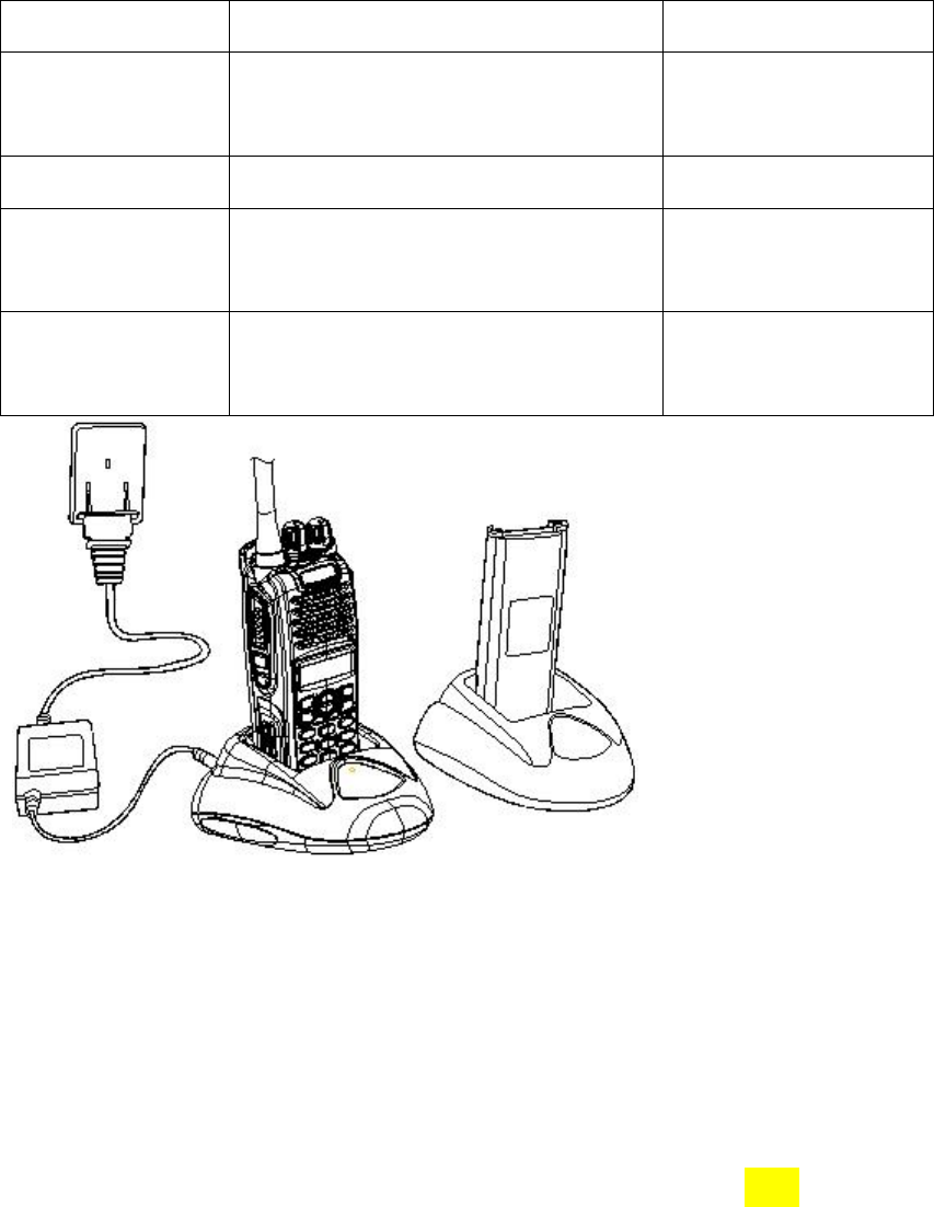
Use only the charger specified by the manufacturer. The charger’s LED indicates the charging progress.
Status Charger LED Remarks
Standby (no-load) Red LED flashes slowly (0.2s on/3s off ) For MCU rapid-rate
charger
Battery is charging Red LED solidly glows
Battery is fully
charged
Green LED solidly glows
Error Red LED flashes rapidly (0.2s on/0.2s
off)
For MCU rapid-rate
charger
Please follow these steps:
1. Plug the power cord into the adapter.
2. Plug the AC connector of the adapter into the AC outlet socket.
3. Plug the DC connector of the adapter into the DC socket on the back of the charger.
4. Place the radio with the battery attached, or the battery alone, in the charger.
5. Make sure the battery is in well contact with the charging terminals. The charging process initiates when the red LED
lights.
6. The greed LED lights about 3 hours later indicating the battery is fully charged. Then remove the radio with the battery
attached or the battery alone from the charger.
Troubleshooting (MCU intelligent rapid-rate charger only):

11
When troubleshooting, always observe the color of the LED:
No LED Indication?
1. Make sure that the power cord is plugged into an appropriate AC outlet.
Red LED flashes rapidly (0.2s on/0.2s off)?
1. Remove the battery from the charger, and:
a) Make sure that it is a HYT authorized battery. Other batteries may not charge.
b) Remove power from the battery charger, and clean the gold metal, charging contacts of the battery and charger,
using a clean dry cloth.
2. The battery temperature may be above 45℃.
3. Defective battery. Please replace it with a new one.
4. Power up the charger and place the battery back into the charger pocket. If the LED indicator continues to flash red,
replace the battery.
Note:
When the battery charger detects the proper battery conditions, rapid charging begins automatically (steady red LED).
If the battery temperature is above 45℃, the charger will report the fault by flashing red LED rapidly (0.2s on/0.2s off),
and will not charge until the battery temperature is below 45℃, with red LED solidly glows (Ni-MH battery only).
Antenna Information
1. Stubby antenna is ideal for communication within limited range. Thin and long antenna optimizes communication
coverage, and its flexible and soft characteristic makes it ideal for wearing your radio on the belt.
2. Communication range may vary with terrain and your operating conditions. Rainy days or forest locations may narrow
your communication range, please make preparation in advance to avoid potential inconvenience.
Assembly and Disassembly
Attaching the Battery
1. When attaching the battery, make sure the battery is in parallel and good contact with the aluminum chassis. The battery
bottom is about 1 to 2 centimeters below the bottom of the radio’s body.
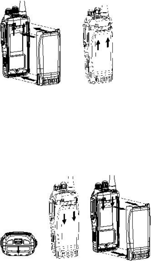
12
2. Align the battery with the guide rails on the aluminum chassis and slide it upwards until a “click” is heard.
3. The battery latch at the bottom locks the battery. See figure 1.
Figure 1
Removing the Battery
1. Turn off the radio before removing the battery.
2. Slide the battery latch, at the bottom of the radio’s body, in the direction indicated by the arrow.
3. Slide down the battery for about 1 to 2 centimeters, and then remove the battery from the radio’s body. See figure 2.
Figure 2
Attaching the Antenna
1. Align the threaded end of the antenna with the radio’s antenna connector.
2. Turn the antenna clockwise to fasten it. See figure 3
Removing the Antenna
Turn the antenna counter-clockwise until you can remove it. See figure 3
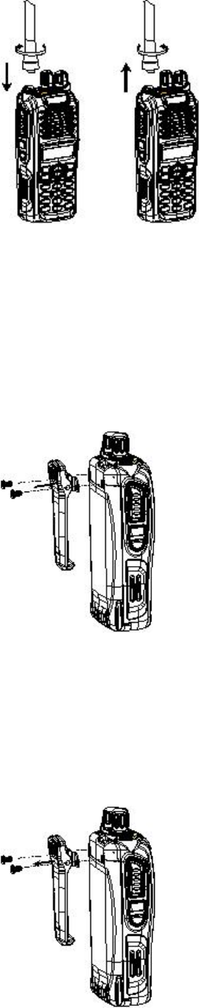
13
Figure 3
Attaching the Belt Clip
1. Remove the screws (belt clip) on the radio’s body.
2. Align the screw holes on the metal holder of belt clip with those on the radio’s body.
3. Tighten the screws. See figure 4.
Figure 4
Removing the Belt Clip
1. Remove the screws (belt clip).
2. Remove the belt clip. See figure 5.
Figure 5
14
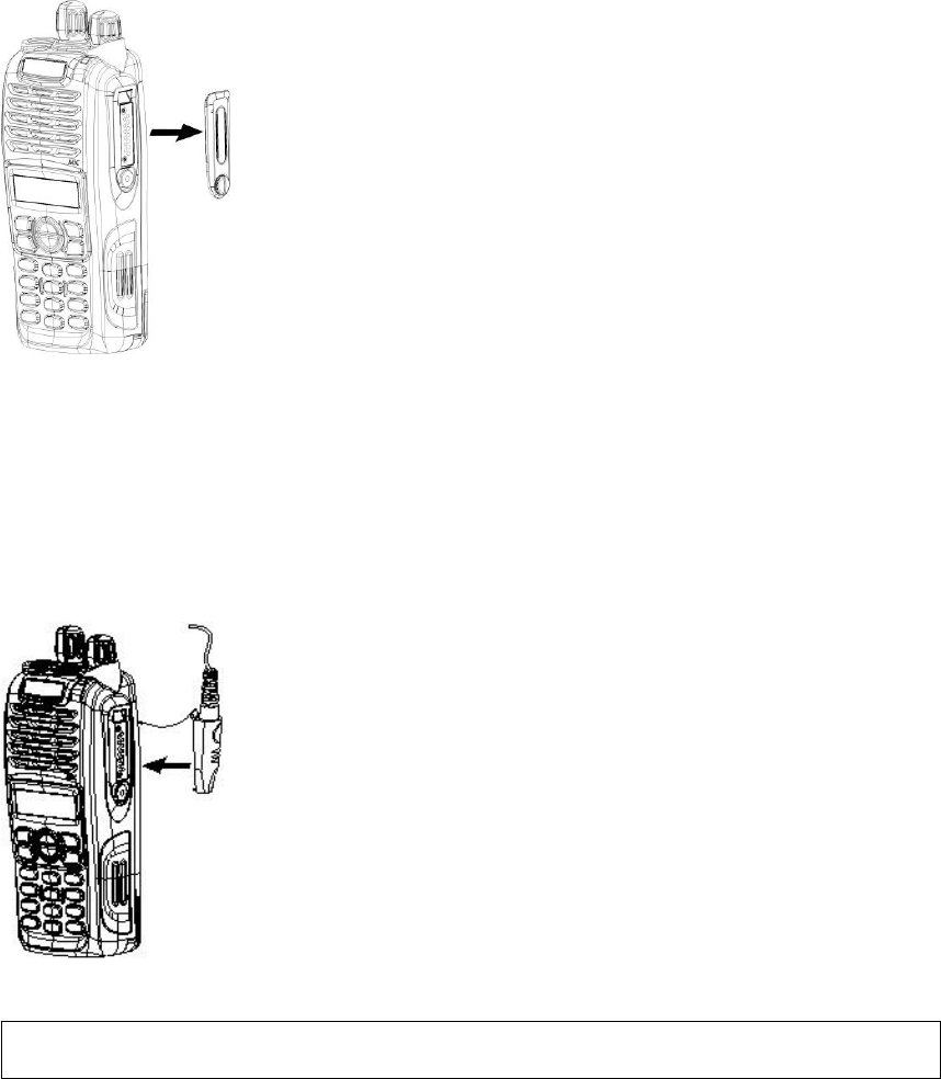
Removing the Accessory Cover
1. Unscrew the screw on the accessory cover counter-clockwise with a flat head screwdriver.
2. Remove the accessory cover. See figure 6.
Figure 6
Attaching the Earpiece/Microphone
1. Insert the tab at the bottom of the earphone/microphone into the slot on the radio.
2. Align the screw at the top of the earphone/microphone with the threaded hole on the radio.
3. Rotate the screw clockwise to fasten. See Figure 7.
Figure 7
Note: The figures above are only for references. Please make the object as the standard.
15
General Radio Operations
Turn On/Off the Radio
Rotate the Radio On-Off/Volume Control knob clockwise to turn the radio on, or counter-clockwise until a “click” is heard to
turn the radio off.
Adjust the Volume
Rotate the Radio On-Off/Volume Control knob clockwise to increase the volume, or counter-clockwise to decrease the

16
volume.
Password
If the Password feature is set, the LCD will display “PSW” after power-on. Input the correct password (1~8 digits) to enter the
conventional mode.
Lock/Unlock
To lock the keypad, press while holding down . When locked, the LCD displays “Key Locked”.
To unlock the keypad, press while holding down . When unlocked, the LCD displays “Key Unlocked”.
Select a Channel
The radio provides 32 conventional channels, some of which may not be programmed and can not be used. Please contact
your dealer for detailed information.
Rotate the Channel Selector knob to select a desired channel.
Transmit
To transmit, press and hold down the PTT key, and speak into the microphone at your normal voice level.
Hold the microphone about 2.5 to 5 centimeters away from your mouth.
Receive
To receive, release the PTT key.
Programmable Auxiliary Functions
Your dealer may assign one of the following auxiliary functions to the TK, SK1, SK2 keys (short or long button-press). Press
the key to enable the function, and press it again to disable the function. Please refer to Advanced Operations.
Trunking Mode:
z Off
z Disconnect
z Emergency
z Hunt
17
z Man Down
z Whisper
z Scrambler
z Power Select
Conventional Mode:
z Off
z Call 1/Call 1
z Emergency
z Emergency Cancel
z Man Down
z Man Down Backup
z Monitor
z Monitor Momentary
z Scrambler
z Scrambler Backup
z Squelch Off
z Squelch Off Momentary
z Talk Around
z Power Select
z Whisper
z Whisper Backup
z VOX
z VOX Backup
z Busy Channel Lock
18
Trunking Mode
Keypad Function
Function Keypad
Exit Key
Up Key
Down Key
Redial Key
Call Back Key
Menu/Select Key
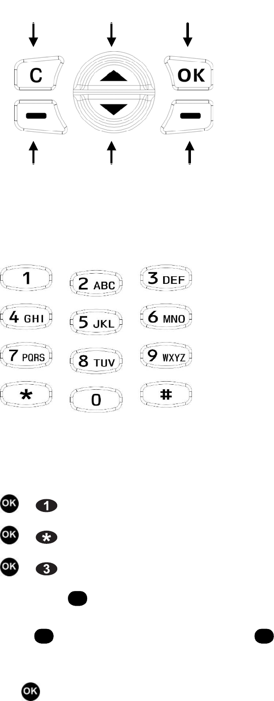
19
Used to enter the menu mode. When you are in the menu mode, this key is also used to make menu selections.
Exit Up Menu/Select
Call Back Down Redial
z Numeric Keypad
Used to enter information for programming the radio’s lists. When the radio operates in trunking mode, the keys are also
used to dial a phone number.
Combined Function Key
+ : used to switch between trunking mode and conventional mode.
+ : used to lock/unlock the keypad.
+ : used to enable/disable Scrambler (valid in trunking mode).
1. Dial Key
#
Press
#
to make a call. Both the PTT key and
#
key are programmed with the same feature to meet personal
requirements, making your operation more convenient.
2. Key

20
Press to enter the lower level menu, or to confirm one item in the menu. When icon appears, press the key to view
missed calls.
3. Exit Key
C
Press
C
to clear the error prompt on the LCD in case of call failure. Each press of
C
will clear the last digit of a
wrong number. Long press
C
to return to the main menu directly.
In addition,
C
is the hang up key for all successful calls.
4. Redial Key
Hold down the Redial key just below , and the last dialled number appears. Press it again to make a call. Or press the
PTT key or
#
to make the call.
5. Call Back Key
Hold down the Call Back key below
C
, and the last caller number appears. Press it again to make a call. Or press the
PTT key or
#
to make the call.
6. Numeric Key
Each digit appears on the LCD as it is entered. Press
C
to clear when a wrong digit is entered.
7. Each valid press of the numeric key is followed by an alert tone.
8. The programmable function keys SK1, SK2 and TK can be programmed as the Manual Hunt key via the programming
software.
When the base station, which the radio currently locks onto, can not provide good voice quality, press the Manual Hunt key
to scan again, in order to search a better base station.
If the Manual Hunt key is held down, scan starts from the current frequency and move downwards in the frequency table. If
the radio disconnects from the network, it will automatically scan from the start frequency in the frequency table, to ensure
Note: If the radio locates at the boundary of two adjacent systems, pressing the key may cause the radio to switch to
the other system. Pay attention to the current channel number and the roaming icon on the LCD during
scanning.

21
the system’s frequencies are scanned with priority.
9. The programmable function keys SK1, SK2 and TK can be programmed as the Disconnect key via the programming
software.
When transmitting on the traffic channel, press the Disconnect key to return to the control channel.
10. The programmable function keys SK1, SK2 and TK can be programmed as the Emergency key via the programming
software.
When the radio is standby on the control channel, press the Emergency key to send an emergency call to a predefined
number (dispatcher number 8170-8180, individual call number, or group call number). The number is set via the
programming software.
11. The programmable function keys SK1, SK2 and TK can be programmed as the Man Down key via the programming
software.
Press the key to enable/disable the Man Down feature.
12. The programmable function keys SK1, SK2 and TK can be programmed as the Scrambler key via the programming
software.
Press the key to enable/disable the Scrambler feature.
13. The programmable function keys SK1, SK2 and TK can be programmed as the Whisper key via the programming
software.
Press the key to enable/disable the Whisper feature.
14. The programmable function keys SK1, SK2 and TK can be programmed as the Power Select key via the programming
software.
Press the key to select the transmit power.
Note: The programmable function keys can be set to long or short button press and can be programmed with respective
functions.
22
Function Description
Power On Status
Power on the radio in trunking mode. Enter the password if power on password is set and “Welcome!” appears on the LCD.
The power on display can be changed in Model Information in the programming software.
Then the radio scans automatically. The LED indicator and at the top right of the LCD flash, indicating the radio is
scanning.
Scan recycles according to the preset mode until the radio has registered successfully. There are four scan modes: control
channel table scan, band scan, all frequency scan and flexible channel plan.
Take all frequency scan for example.
After the radio has registered successfully, the LCD displays “Register Success” and icon appears at the top right of the
LCD, indicating the radio has automatically locked onto the local system. If the radio roams to other systems, icon
appears at the top right of the LCD. If the radio does not lock onto a system, scan recycles automatically. Whether to display
is dependant on the roaming icon display parameters set in the programming software. Please refer to the Help File of
the programming software for details.
After the radio has registered successfully, the radio will enter the standby status automatically with green LED flashing. The
LCD displays ID or number/alias of the work group in which the radio is in before power-off.
Chinese/English Menu
Scan Channel XXXX
Welcome!
ID XXXXXXXXXX
01 taking part in XXXXXXXXX
01 Vice Squad 1
Note: Pay attention to the use of the long or short press definitions. The short press is not applicable for all features. Man
Down and Whisper features must be enabled/disabled via long button press. It is recommended to fix the use in the
programming software.

23
The dot matrix display and simple Chinese/English menus make operations easy for TC-780M. This feature can be set in
item 7 Language Select in the menu.
Auto Select BS
The advanced scan technology enables the radio to always lock onto the BS with stronger signals, ideally suited for the
multiple BS covered system. As for the single BS covered system, this feature can be disabled. This feature can be set in
the Background Scan item (sub-menu of control channel) of trunking system setting in the programming software.
Full Off Air Call Setup (FOACSU)
The feature is available after both the calling and called parties are set with the feature. If the feature is set, the called radio
rings when the calling radio transmits. However, the system does not allocate a traffic channel to the two parties until the
PTT key of the called party is pressed to respond to the call. This feature can save channel resources and can be set in
basic information of trunking system setting in the programming software. It asks for system support.
Manual Select BS
The radio can quickly switch to the designated control channel via combined keys. Press + 4-digit
FCC value +
#
to scan on the channel directly.
A: For control channel table scan, the 4-digit FCC value is within the FCC range listed in the channel.
B: For all frequency scan, the 4-digit FCC value is between the start channel and stop channel of all frequency scan.
C: For flexible channel plan, the 4-digit FCC value is within the control channel range listed in the flexible channel table.
D: For band N scan, the 4-digit FCC value is within the range listed in band N. N is set in the programming software.
Flexible Channel Plan
Tx/Rx frequency on the used control/traffic channel can be set by the user in the programming software. This feature can
meet irregular channel frequencies of users.
Note: When selecting BS manually, the input range of the 4-digit FCC value is limited and is dependant on the radio’s
current scan mode.
Note: The set frequency must be a whole-number multiple of 1.25kHz.

24
Kill/Revive
Through the base station, a lost radio may be remotely killed, and a killed radio can be remotely revived.
Compandor
The feature effectively improves the dynamic range of voice signal and enhances the SNR of the given frequency deviation.
Decreased background noise insures a transmission of clear voice even in noisy environment. The feature can be set in
basic information of the programming software and can be enabled/disabled manually in the menu.
Whisper
The feature allows you to speak quietly into the radio and still be heard clearly. This feature can be checked in basic
information of the programming software and can be enabled manually in the radio menu.
Man Down
If the feature is enabled, the radio will send the emergency message to the system when the radio is horizontally or inversely
positioned for a certain period (set via the programming software). The feature can be enabled via the shortcut key or in the
menu and can be used under special environments.
Safety Check
The system sends a Safety Check signalling to the radio at intervals and the radio sounds a special alert. Press the PTT key
to acknowledge, indicating safe situation. If the PTT key is not pressed, the alert keeps sounding.
Special ID Calling
The user can assign 101 with a specific ID number, such as all call number, wired dispatcher number. Refer to the sub-item
of Manual Dial for details.
Temporary Grouping in Roaming System
Manually change the system code (PFIX) to join the temporary grouping of the roaming system. Refer to the sub-item of
Manual Dial for details.
Missed Call Display
Icon appears, reminding the user of the missed call. This feature is not required to be set. Enter Call Record in the
menu to view.
Calling Party Number Display
During a group call, the radio can display the number of the calling party for caller identification.
High/Low Power Switchable

25
By simple pressing one button, users can switch to low power when communicating within limited range coverage or switch
to high power when further distance is required. The feature can be set in Radio Setting in the menu.
Customized Display
LCD displays the radio’s ID, group call alias and group call number when the radio is standby. This feature can be set in
CPSX or MPT1343 terminal grouping in the programming software.
LCD Icons
LCD icons provide quick recognition of battery strength, signal strength, transmit power, vibrate, roam, man down, whisper,
etc.
Customized Programming Interface
The simple programming interface (in Chinese/English) is customized for your easier operation and test.
Four System Networks
The user may define parameters for three trunking networks and one conventional network. The current operating network
can be selected manually in the radio.
Transmit a Call
The radio can transmit various calls, including individual call, group call, call to PABX/PSTN subscriber, via group call list or
manual dial.
Individual Call
The radio can transmit an individual call by entering the called party’s number via the keypad. The radio enters
non-encryption or encryption mode according to the preset mode when communicating. Press the user-defined keys +
to quickly switch between non-encryption and encryption mode. The radio returns to the preset mode after hang-up.
Group Call
TC-780M radio can be set with 82 groups at most. Rotate the Channel Selector knob to select a group of the local system
or roaming system as the current group. Rotate the Channel Selector knob to view the property and number of the group,
which are displayed on the LCD, as join group 205-20-900 (CPSX dial). The group alias can be set to be displayed. Press
the PTT key to call the current group. The calling party displays remaining time; the called party displays the caller ID and
time (when the called party receiving), and displays group number and time upon no transmission.
The talk group can be categorized into hidden group, join group, simulcast group, ack group, temporary group, data group
and encryption group.
Hidden Group: This group can only receive calls, but can not transmit calls. Hidden group can be called with the Group Call
Selector at any position, but not displayed in the group call list.

26
Join Group: This group can not only receive calls, but also transmit calls. When called, the radio can only acknowledge in
individual call and in current group.
Simulcast Group: It is same with join group, but PFIX is not compared.
Ack Group: The group can both receive and transmit calls with the Group Call Selector at any position.
Temporary Group: It is grouped with dynamic regrouping command. Its functions are same with those of ack group.
Data Group: The group can only respond to the data group call from the radio, and other radios won’t respond to the call
even if they join this group. This group is mainly used for data transmission.
Encryption Group: When this group talks, members in this group enters encryption mode automatically. After disconnect,
they return to non-encryption or encryption mode, which is set during standby. Other functions are same with those of ack
group.
Receive Broadcast Message
The radio can receive broadcast messages sent by the system on the control channel, to accomplish the following functions:
add control channel frequency, delete control channel frequency, specify call maintenance parameters, specify registration
parameters, etc. Please refer to the MPT1327 signaling standard for details.
Note 1: Encryption is enabled in encryption mode and encryption is not enabled in non-encryption mode.
Note: 2: In group call mode, the radio only responds to current group, hidden group, fleet-wide all call, ack group,
encryption group, temporary group, system-wide all call and individual group, but not responds to calls of other join
groups.
Note 3: PFIX can be set whether to be compared via the programming software for the above groups except simulcast
group.

27
Other Features
1. Dynamic Calling Party Number Display
If the calling party and called party are in the same fleet, the called party will display the number of the calling party
dynamically.
2. Time-Out Timer (TOT)
Set the amount of time the radio user can continuously transmit on a channel via the TC-780M programming software. The
timer counts down upon transmission. When the timer expires, the radio will stop transmitting automatically.
3. Fleet Call Inhibit
Calls (individual call/group call) are prohibited on some fleets by selecting hidden at the corresponding fleets in the TC-780M
programming software. This feature only supports CPS dial.
4. VoteNow
After the VoteNow feature is enabled via the programming software, the radio will compare the signal strength of the
broadcast BS with that of the currently locked BS. This feature asks for system support.
LCD Display
Note: Only one frequency can be added for the radio each time if more than one frequency is added for the system. You
can add another frequency via manual scan or turning the radio off and back on. Same operations for deleting
frequencies. This feature asks for corresponding function support of the system.
Note: This feature asks for system support, that is to say, the system must transmit broadcast messages on control
channel, notifying all radios to send their own ID for message maintenance when the PTT key is pressed.
Note: The TOT feature is only applicable for the calling party. The called party only displays the actual communication
time.
28
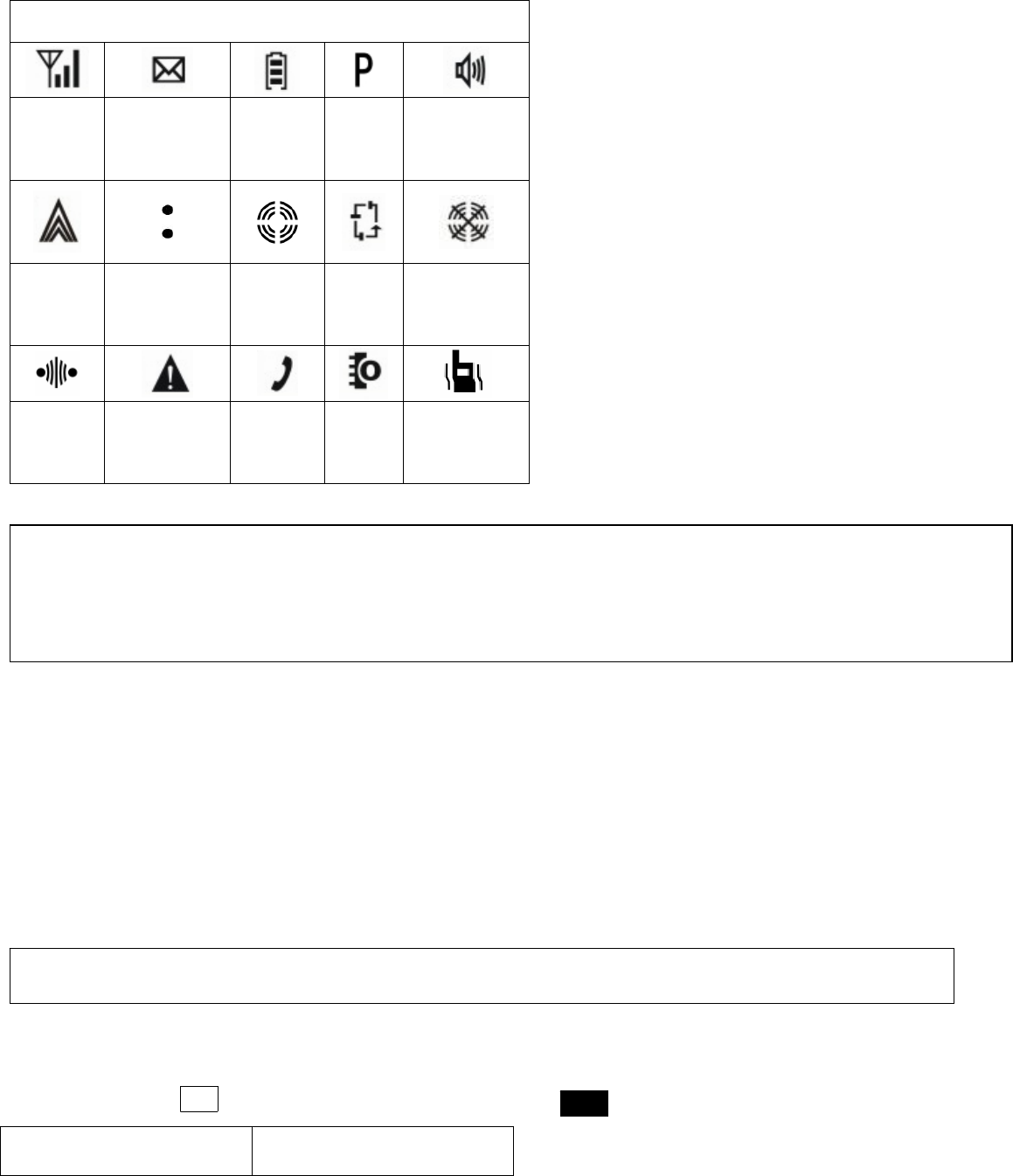
In trunking mode, icons displayed on the LCD are as follows:
Icons and Indications
Signal
Strength
Status
Message
Battery
Strength
Call
Forward
Speaker
Unmute
Transmit
Power Transmit Lock Scan Roam
Scrambler Man Down Missed
Call Whisper Vibrate
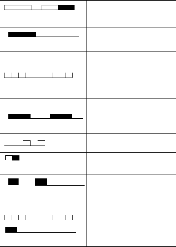
Signal Tone
The radio provides a series of audible tones which can tell the operating status of the radio along with the LCD display.
Signal tones include high-pitched and low-pitched tones. The operating statuses are indicated by changes in alert time,
sequence and interval.
When being called, the radio will continuously sound an alert tone until the PTT key is pressed.
High-pitched Tone Low-pitched Tone
Signal Tone Indication
Note: After the individual call is connected, the called radio rings continuously and displays the number of the calling
party simultaneously. After the PTT key is pressed, the radio stops ringing. The communication time, which starts upon
the radio’s ringing, is displayed.
Note: A different, rapid beep tone is employed for Low Battery Alert.
29
Power on/revive
Call failure
Successfully called by other
radios or PSTN/PABX
subscribers
System handling failure
Successful call setup
Hang up
Grouped into the dynamic
temporary grouping
System call by the dispatcher
Dial error
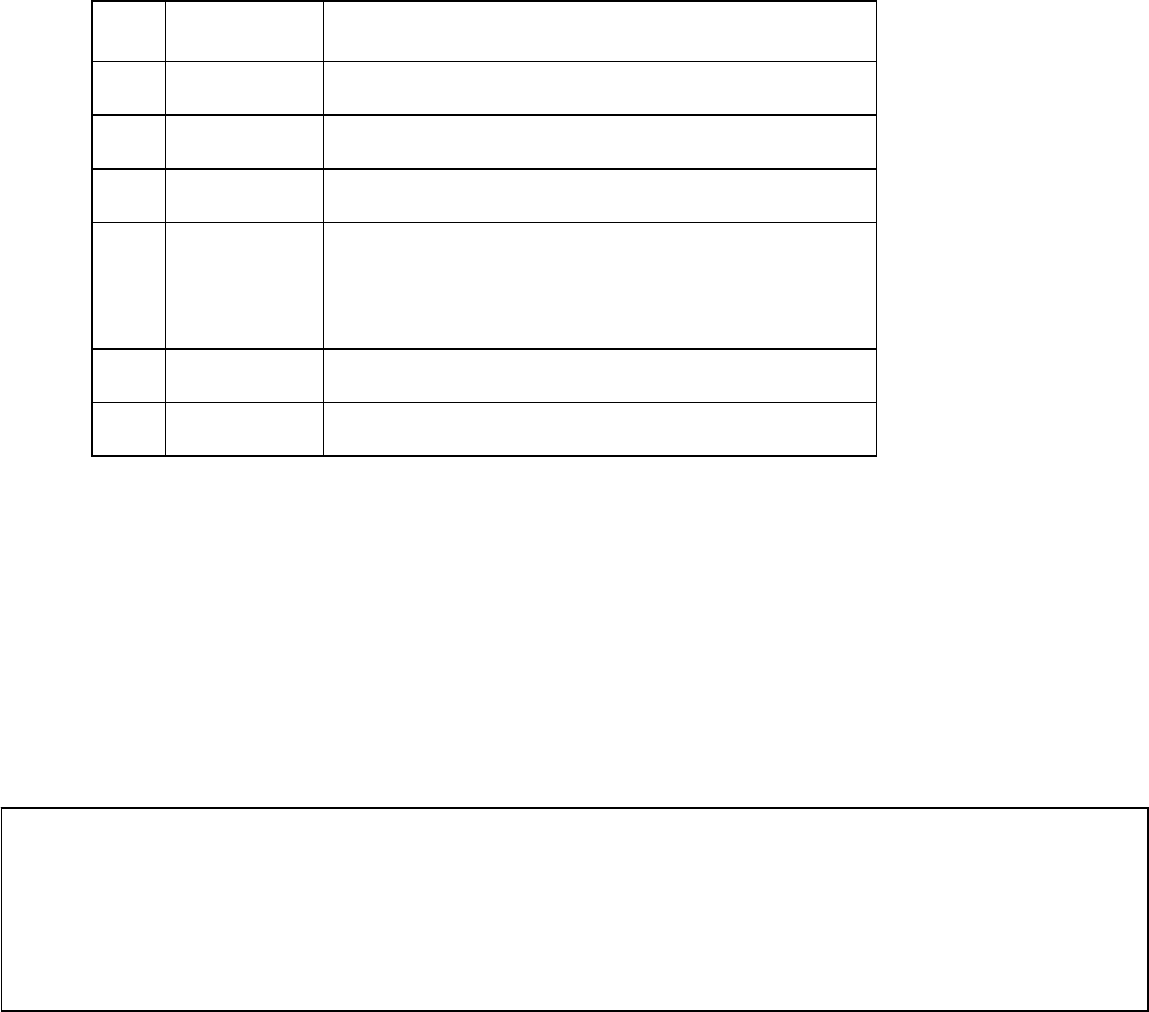
LED Indicator
The LED indicator located between the antenna and Channel Selector knob indicates the operating status of the radio to
some extent.
30
Programming
The radio is programmed with the dedicated programming cable and software. Operations are as follows:
1. Connect the radio to the PC serial port with the programming cable.
2. Power on the radio.
3. Run the programming software.
Remove the programming cable after programming is completed.
Manual Dial
The radio supports CPSX and MPT1343 numbering schemes. PABX call, PSTN call, emergency call, priority call, call
forward and any group call can be made only when the corresponding right is programmed.
If Fleet Individual Call Inhibit is set in the programming software, individual calls are prohibited on the corresponding fleet. If
Fleet Group Call Inhibit is set, group calls are prohibited on the corresponding fleet. This setting can limit the user’s call right.
CPSX Manual Dial
No. LED Indication
1 Not light Power off or flat battery
2 Green Receiving in the network
3 Red Transmitting in the network or in talk around mode
4 Flash Green The radio locks onto a system. The flash frequency is
dependant on the frame length of the current system
signalling.
5 Flash Red Poor signal, code error
6 Flash Orange Scanning
Precautions:
1. Install the programming software into your computer first.
2. Many functions can be set via the programming software. Read the Help File of the programming software carefully
before programming.

31
1. Radio to Radio
The radio can make radio-to-radio individual call and group call. After Any Group Call Right is programmed, any group call
can be made. If there is no any group call right, the radio can only transmit calls in the group call list.
z In-fleet Individual Call
3-digit ID number (200~899) +
#
or PTT
z In-fleet Group Call
3-digit group call number (900~999) +
#
or PTT
z Fleet-wide All Call
#
or PTT
z Inter-fleet Individual Call
5-digit ID number (20~79 + 200~899) +
#
or PTT
z Inter-fleet Group Call
5-digit group call number (20~79 + 900~999) +
#
or PTT
z Inter-fleet All Call
5-digit all call number +
#
or PTT
z Interprefix Individual Call
8-digit ID number (200~327 + 20~79 + 200~899) +
#
or PTT
z Interprefix Group Call
8-digit ID number (200~327 + 20~79 + 900~999) +
#
or PTT
Hang Up: Press
C
or the Disconnect key.
2. Radio to PABX/PSTN
The radio can call PABX and PSTN subscribers.
1) Radio to PABX
The radio can call 4~8 digit PABX number. When the PABX number exceeds 4 digits, prefix or is required in
Note: When the fleet number of inter-fleet call reachs 70, please dial the system PFIX before the fleet number because of
the conflict with leading character of the PABX call.

32
the number.
z 4-digit Extension PABX
4-digit PABX number +
#
or PTT
e.g.:
#
z 5~8 Digit Extended Addressing PABX
+5~8 digit PABX number+
#
or PTT
2) Radio to PSTN
+ telephone number +
#
or PTT
The telephone number including DDD and IDD number is 3~15 digits.
Hang Up: Press
C
or the Disconnect key.
3. Special Call
1) Emergency Call
The emergency call has the highest call priority.
z Emergency In-fleet Call
+ 3-digit individual call or group call number +
#
or PTT
z Emergency Inter-fleet Call
+ 5-digit individual call or group call number+
#
or PTT
z Emergency Inter-zone Call
+8-digit individual call or group call number+
#
or PTT
z Emergency Call to PABX/PSTN
This operation is more or less the same with radio-to-PABX/PSTN operation except that prefix is
required here.
Hang Up: Press
C
or the Disconnect key
2) Priority Call

33
This call has call priority.
z Priority In-fleet Call
+ 3-digit individual call or group call number+
#
or PTT
z Priority Inter-fleet Call
+ 5-digit individual call or group call number +
#
or PTT
z Priority Call to PABX/PSTN
This operation is more or less the same with radio-to-PABX/PSTN operation except that prefix is required
here.
Hang Up: Press
C
or the Disconnect key
3) Call Forward
Forward the incoming call to another radio and PABX/PSTN subscribers.
z Forward to Another Radio
+ individual call or group call number +
#
or PTT
z Forward to PABX
4-digit extension PABX:
+ 4-digit PABX number+
#
or PTT
5~8 digit extended PABX:
+ or + 5~8 digit PABX number+
#
or PTT
z Forward to PSTN
+ 3~15 digit PSTN number+
#
or PTT
The PSTN number including area code has a maximum of 15 digits.
z Cancel Call Forward
4) Short Data (CPSX manual dial)
34
1~25 digit short data can be sent between portable radios.
+3, 5 or 8 digit ID number+ +1~25 digit number +
#
or PTT
5) Include Call
After a call is established, enter 3, 5 or 8 digit ID number +
#
Hang Up: Press
C
or the Disconnect key
6) RQQ Status Message
The status message is a code used to transfer the preset information and needs system support. For example, status “08”
indicates “on mission”. Preset the English information with 16 English characters through programming.
+3, 5 or 8 digit ID number + + 2-digit number among 00~31+
#
(32 statuses can be defined in all)
7) Emergency: Use the Emergency key.
8) PFIX Manually Grouped into Temporary Grouping
This feature can enable the radio to join the temporary grouping when roaming.
Rotate the Work Group Selector to the specified temporary group and then enter + 3-digit PFIX +
#
The 3-digit PFIX is a number among 200~327 specified by MPT1343.
9) Special ID Calling
Note: The Temporary Grouping feature can only be used within the local system, because MPT1327 and the police
use standard does not specify PFIX in temporary grouping signaling. Ease of use, this feature is ideal for policemen
on mission in other areas.
Note: Calls made by the special function key are emergency calls. When this function is used, the radio must have
emergency call right.
35
Preset a special ID number to 101 through keypad operations + XXXXXXX + . The 7-digit ID number
“XXXXXXX” is 3-digit PFIX plus 4-digit ID number among 8136~8191. The radio can transmits a call to the set ID by dialling
101 and will not lose the set ID number even if it is powered off.
10) Call to Dispatcher
According to the police use standard, the radio can call several dispatchers. The following table lists the dispatchers’ ID
corresponding to dial numbers.
Table 1
No. Dial No. ID
1 8170
2 8171
3 8172
4 8173
5 8174
6 8175
7 8176
8 8177
9 8178
10 8179
MPT1343 Manual Dial
Note: Calls directly transmitted to the following dispatchers are common calls. To transmit emergency call to the
dispatchers, prefix is required.

36
1. Radio to Radio
The radio can make radio-to-radio individual call and group call. After Any Group Call Right is programmed, any group call
can be made. If there is no any group call right, the radio can only transmit calls in the group call list.
z In-fleet Individual Call
2-digit ID number (20~89) +
#
or PTT
3-digit ID number (200~899) +
#
or PTT
z In-fleet Group Call
2-digit ID number (90~98) +
#
or PTT
3-digit group call number (900~998) +
#
or PTT
z Inter-fleet Individual Call
6-digit ID number with a leading digit in the range 2~6 (2001~6050 + 20~89)+
#
or PTT
7-digit ID number with a leading digit in the range 2~6 (2001~6050 + 200~899) +
#
or PTT
z Inter-fleet Group Call
6-digit ID number with a leading digit in the range 2~6 (2001~6050 + 90~98) +
#
or PTT
7-digit ID number with a leading digit in the range 2~6 (2001~6050 +900~998) +
#
or PTT
z Interprefix Individual Call
9-digit ID number with a leading digit 2 or 3 (200~327 + 2001~6050 + 20~89) +
#
or PTT
10-digit ID number with a leading digit 2 or 3 (200~327 + 2001~6050+ 200~899)+
#
or PTT
z Interprefix Group Call
9-digit ID number with a leading digit 2 or 3 (200~327 + 2001~6050 + 90~98) +
#
or PTT
10-digit ID number with a leading digit 2 or 3 (200~327 + 2001~6050 + 900~998) +
#
or PTT
Hang Up: Press
C
or the Disconnect key
2. Radio to PABX/PSTN
The radio can call PABX and PSTN subscribers.

37
1) Radio to PABX
1. 0 +
#
or PTT: call short addressing PABX (ID=8000)
0 + 3~6+
#
or PTT: call short addressing PABX (ID=8000)
1000~8999 +
#
or PTT: call 4-digit short addressing PABX
3~6+1000~8999 +
#
or PTT: call 4-digit short addressing PABX
0, 7, 8 + PABX number (4~6 digit)
7, 8 + PABX number (4~8 digit)
2) Radio to PSTN
+ telephone number +
#
or PTT
The telephone number including DDD and IDD number is 7~20 digits.
Hang Up: Press
C
or the Disconnect key
3. Special Call
1) Emergency Call
The emergency call has the highest call priority.
+ individual call or group call number +
#
or PTT
z Emergency Call to PABX/PSTN
This operation is more or less the same with radio-to-PABX/PSTN operation except that prefix is required
here.
Hang Up: Press
C
key
In addition, 999 +
#
or PTT: (ID=8180)
Note: Calls made by the special function key are emergency calls. When this function is used, the radio must have
emergency call right.

38
2) Call Forward
Forward the incoming call to another radio and PABX/PSTN subscribers.
z Forward to Radio
+ individual call or group call number +
#
or PTT
z Forward to PABX
+ PABX number +
#
or PTT
z Forward to PSTN
+4~15 digit number +
#
or PTT
The PSTN number including area code has a maximum of 15 digits.
z Cancel Call Forward
#
or PTT
3) Short Data Transmit
1~25 digit short data can be sent between portable radios.
+ data + + called party’s number +
#
or PTT
4) RQQ Status Message
The status message is a code used to transfer the preset information, which needs system support. For example, status “08”
indicates “on mission”. Preset the English information with 16 English characters through programming.
+ 3, 5 or 8 digit ID number + + 2-digit number among 00~31 +
#
(32 statuses in all can be
programmed)
5) Emergency Alarm:
Press the Emergency key, and the radio will transmit emergency call to the dispatcher or other terminals.
6) Abbreviated Dialling
20~29 + 200~998 + PTT
90~99 + 200~998 + PTT
200~299 + 20~98 + PTT
900~999 + 20~98 + PTT
7) Call to Dispatcher
39
This feature is consistent with CPS.
8) Direct Call to Called Party (MPT1327 dial)
1+ PFIX (000~127) + ID (0001-8100)
e.g.: 1 0120246
40
Menu Operation
11. Sys Code
13. Channel Number
15. Fre
q
Ran
g
e
17. Edit
12. PFIX
14. Signal Strength
16. Software Ver
10 Messages
21. Control Channel Table
22. All Frequency
24. Band (1~50)
91. Dialed Calls
(
10 records
)
92. Received Calls (10 records)
Off, 1~5
20 Short Data Records
Chinese/English
Trunkin
g
S
y
s
(
1~3
)
/Conventional S
y
s
(
1
)
23. Flexible Channel Plan
93. Missed Calls (10 records)
Menu
1. Sys Info
2. Scan Mode
3.Status Message
4.Radio Setting
5. Alert Tone Volume
6. Short Data
7. Language Select
8. Mode Select
9.Call Record
41
Menus
1. Sys Info
Group Number/Alias
Mute, Ringing, Vibrating, Ringing+Vibrating
Off, 1~5
42. Power Select
43. Backli
g
ht
44. Group Call Mode
4
5
. In
co
min
g
Ca
ll Al
e
rt
4
6
. V
O
X L
e
v
e
l
4. Radio Setting
4
8
.Tx
/
Rx
S
wit
c
h Tim
e
4
9
. V
o
t
e
N
o
w
0 ~ 255
41. S
q
uelch Level
47. Scrambler
4A
Co
m
pa
n
do
r
4B Whi
spe
r
4
C
M
a
n D
o
wn
4D
Sa
f
e
t
y
C
h
ec
k
On/Off
On/Off/Auto
High/Low
Off, 1 9
42
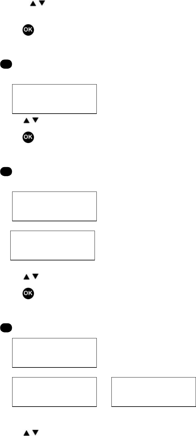
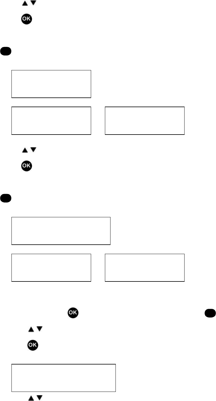
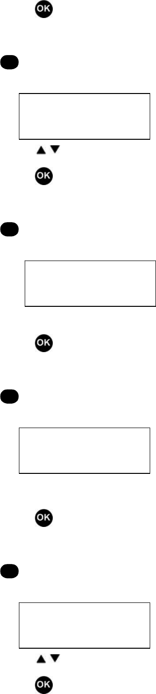
(1) In TMO mode, press in standby mode to enter the main menu, or
C
to exit.
(2) Press / to select your desired menu (e.g. “Sys Info”).
(3) Press to enter “Sys Info”.
(4) Press / to select items upwards/downwards.
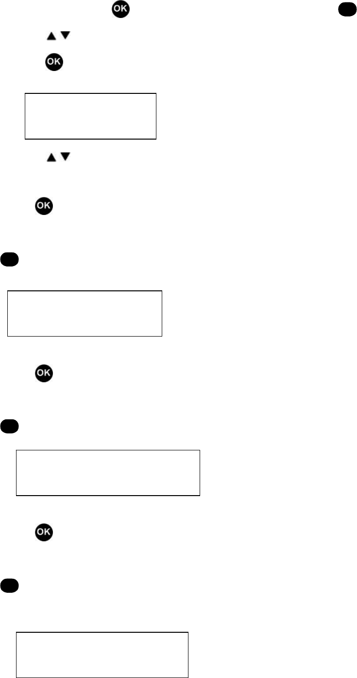
“11 Sys Code”
Press to save the setting and return to “Sys Info”
-or-
C
to return to “Sys Info” without saving the setting.
“12 PFIX”
Press to save the setting and return to “Sys Info”
-or-
C
to return to “Sys Info” without saving the setting.
“13 Channel Number”
Press to save the setting and return to “Sys Info”
-or-
C
to return to “Sys Info” without saving the setting.
“14 Signal Strength”
1 Sys Info
11 Sys Code XXXX
13 Channel Number XXXX
12 PFIX XXX
43
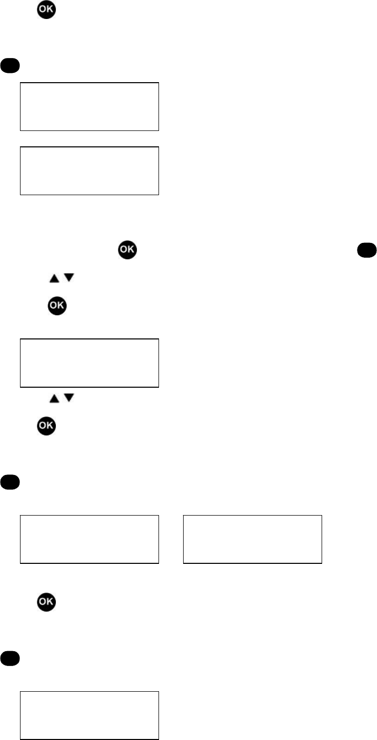
Press to save the setting and return to “Sys Info”
-or-
C
to return to “Sys Info” without saving the setting.
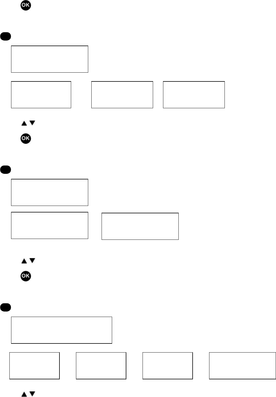
“15 Freq Range”
Press to save the setting and return to “Sys Info”
-or-
C
to return to “Sys Info” without saving the setting.
“16 Software Ver”
Press to save the setting and return to “Sys Info”
-or-
C
to return to “Sys Info” without saving the setting.
“17 Edit”
Press to save the setting and return to “Sys Info”
-or-
C
to return to “Sys Info” without saving the setting.
2. Scan Mode
(1) In TMO mode, press in standby mode to enter the main menu, or
C
to exit.
14 Signal Strength XXXXdbm
15 Freq Range XXX~XXXM
16 VX . XX . XX . XXX
17 Edit Month/Date/Year
44
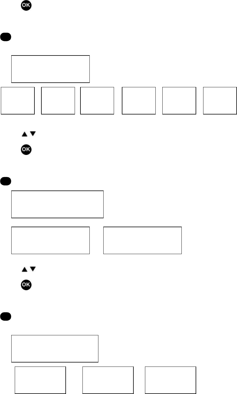
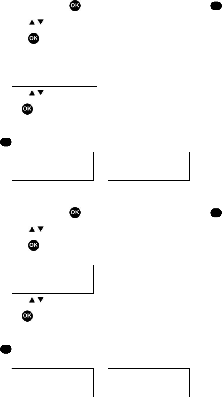
(2) Press / to select your desired menu (e.g. “Scan Mode”).
(3) Press to enter “Scan Mode”.
(4) Press / to select items upwards/downwards.
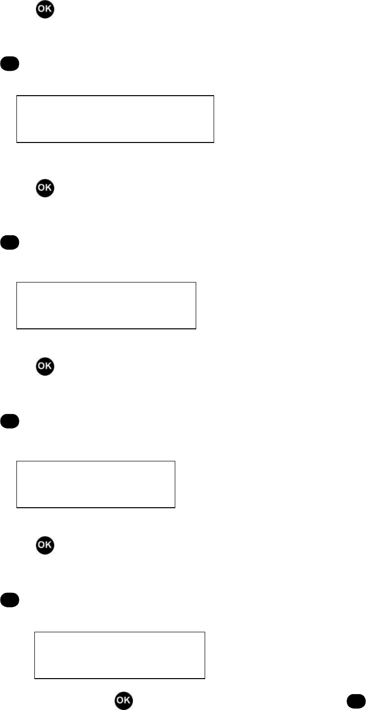
“21 Channel Table”
Press to save the setting and return to “Scan Mode”
-or-
C
to return to “Scan Mode” without saving the setting.
“22 All Frequency”
Press to save the setting and return to “Scan Mode”
-or-
C
to return to “Scan Mode” without saving the setting.
“23 Flexible Channel Plan”
Press to save the setting and return to “Scan Mode”
-or-
C
to return to “Scan Mode” without saving the setting.
“24 Band”
Press to save the setting and return to “Scan Mode”
-or-
C
to return to “Scan Mode” without saving the setting.
2 Scan Mode
21 Control Channel Table
22 All Frequency
23 Flexible Channel Plan
45
3. Status Message
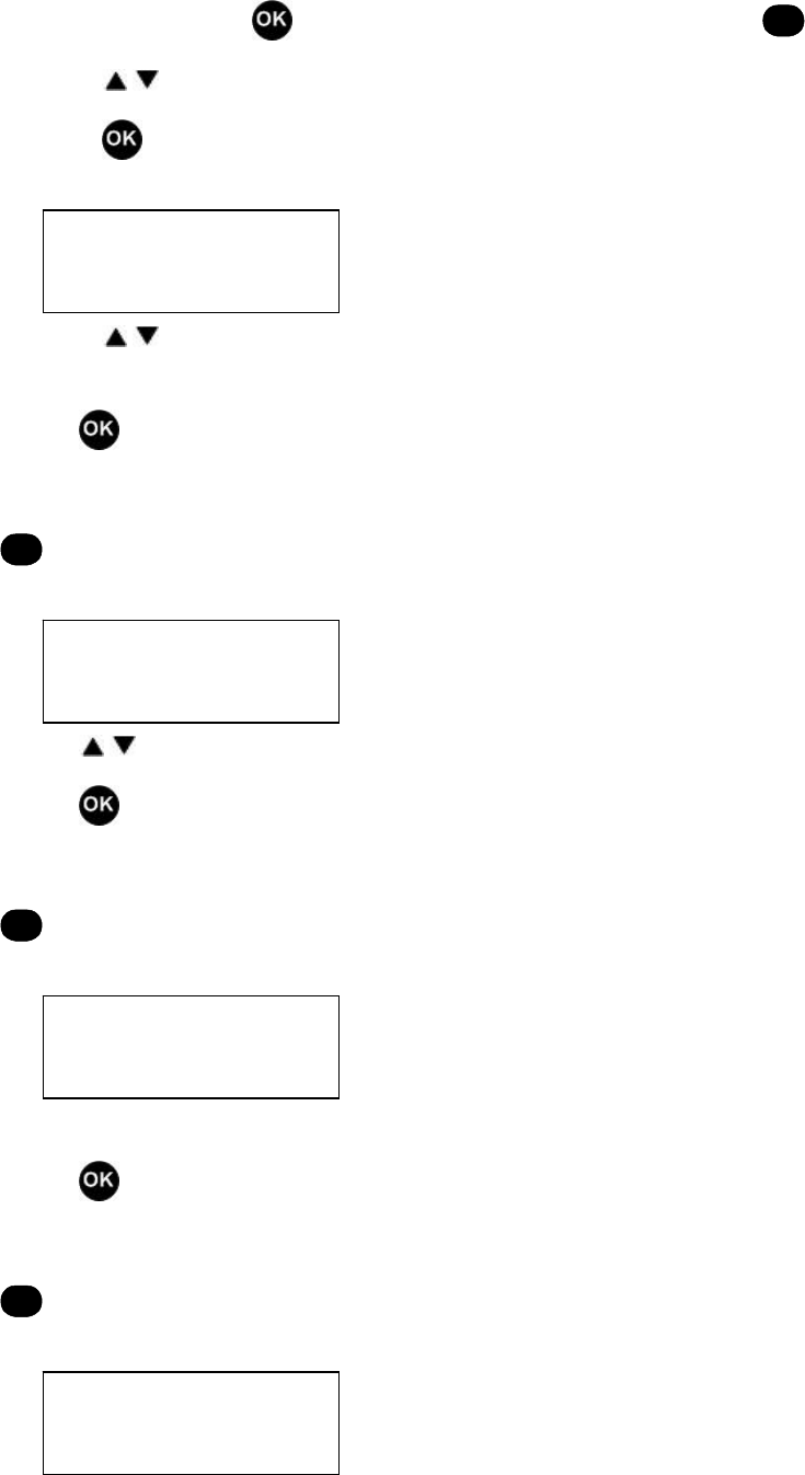
(1) In TMO mode, press in standby mode to enter the main menu, or
C
to exit.
(2) Press / to select your desired menu (e.g. “Status Message”).
(3) Press to enter “Status Message”.
(4) Press / to select a status message (10 message locations in all).
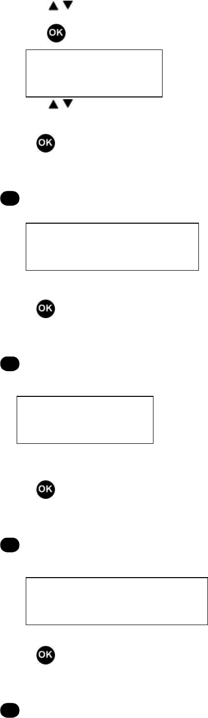
“Status Message”
Press to save the setting and return to “Status Message”
-or-
C
to return to “Status Message” without saving the setting.
There is a “Delete All?” option between location 30 and location 39.
Press to delete and return to “Status Message”
-or-
C
to return to “Status Message” without deleting.
4. Radio Setting
(1) In TMO mode, press in standby mode to enter the main menu, or
C
to exit.
(2) Press / to select your desired menu (e.g. “Radio Setting”).
(3) Press to enter “Radio Setting”.
3 Status Message
30: Null
No Delete All? Yes
4 Radio Setting
39: Null
24 Band 01~50
46
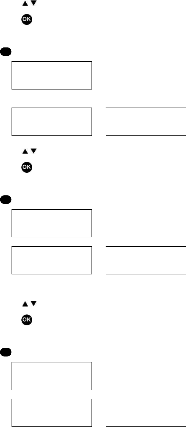
(4) Press / to select items upwards/downwards.
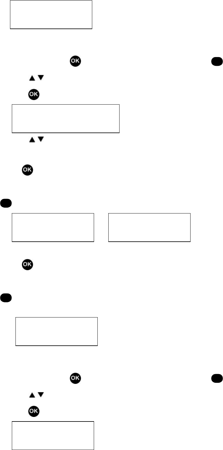
“41 Squelch Level”
Press to save the setting and return to “Radio Setting”
-or-
C
to return to “Radio Setting” without saving the setting.
Press / to select a desired squelch level (off, 1~9).
Press to save the setting and return to “41 Squelch Level”
-or-
C
to return to “41 Squelch Level” without saving the setting.
“42 Power Select”
Press / to select the power (high/low).
Press to save the setting and return to “42 Power Select”
-or-
C
to return to “42 Power Select” without saving the setting.
“43 Backlight”
Press / to select On/Off/Auto.
41 Squelch Level
42 Power Select
1~9
Off
High
Low
47
Press to save the setting and return to “43 Backlight”
-or-
C
to return to “43 Backlight” without saving the setting.
“44 Group Call Mode”
Press / to select Group Number/Alias.
Press to save the setting and return to “44 Group Call Mode”
-or-
C
to return to “44 Group Call Mode” without saving the setting.
“45 Incoming Call Alert”
Press / to select Mute/Ringing/Vibrating/Ringing+Vibrating.
Press to save the setting and return to “45 Incoming Call Alert”
-or-
C
to return to “45 Incoming Call Alert” without saving the setting.
“46 VOX Level”
Press / to select a desired level (Off, 1~5).
43 Backlight
On
Off
44 Group Call Mode
Group Number
Alias
45 Incoming Call Alert
Mute
Ringing
Vibrating
Ringing+Vibrating
Auto
48
Press to save the setting and return to “46 VOX Level”
-or-
C
to return to “46 VOX Level” without saving the setting.
“47 Scrambler”
Press / to toggle the feature On/Off.
Press to save the setting and return to “47 Scrambler”
-or-
C
to return to “47 Scrambler” without saving the setting.
“48 Tx/Rx Switch Time”
Press / to select the time (0~255).
Press to save the setting and return to “48 Tx/Rx Switch Time”
-or-
C
to return to “48 Tx/Rx Switch Time” without saving the setting.
“49 VoteNow”
46 VOX Level
Off
48 Tx/Rx Switch Time
0
……
255
47 Scrambler
On
Off
1
2
3
4
5
49
Press / to toggle the feature On/Off.
Press to save the setting and return to “49 VoteNow”
-or-
C
to return to “49 VoteNow” without saving the setting.
“4A Compandor”
Press / to toggle the feature On/Off.
Press to save the setting and return to “4A Compandor”
-or-
C
to return to “4A Compandor” without saving the setting.
“4B Whisper”
Press / to toggle the feature On/Off.
Press to save the setting and return to “4B Whisper”
-or-
C
to return to “4A Whisper” without saving the setting.
49 VoteNow
On
Off
4A Compandor
On
Off
4B Whisper
On
Off
50
“4C Man Down”
Press / to toggle the feature On/Off.
Press to save the setting and return to “4C Man Down”
-or-
C
to return to “4C Man Down” without saving the setting.
“4D Safety Check”
Press / to toggle the feature On/Off.
Press to save the setting and return to “4D Safety Check”
-or-
C
to return to “4D Safety Check” without saving the setting.
5. Alert Tone Volume
(1) In TMO mode, press in standby mode to enter the main menu, or
C
to exit.
(2) Press / to select your desired menu (e.g. “Alert Tone Volume”).
(3) Press to enter “Alert Tone Volume”.
(4) Press / to select a desired level (Off, 1~5).
5 Alert Tone Volume
4C Man Down
On
Off
4D Safety Check
On
Off
51
Press to save the setting and return to “Alert Tone Volume”
-or-
C
to return to “Alert Tone Volume” without saving the setting.
6. Short Data
(1) In TMO mode, press in standby mode to enter the main menu, or
C
to exit.
(2) Press / to select your desired menu (e.g. “Short Data”).
(3) Press to enter “Short Data”.
(4) Press / to select short data (20 records in all).
Press to save the setting and return to “Short Data”
-or-
C
to return to “Short Data” without saving the setting.
There is a “Delete All?” option between the first data record and the last data record.
Press to delete and return to “Short Data”
-or-
C
to return to “Short Data” without deleting.
Off
1~5
6 Short Data
60: Null
No Delete All? Yes
619: Null
52
7. Language Select
(1) In TMO mode, press in standby mode to enter the main menu, or
C
to exit.
(2) Press / to select your desired menu (e.g. “Language Select”).
(3) Press to enter “Language Select”.
(4) Press / to select Chinese/English.
Press to save the setting and return to “Language Select”
-or-
C
to return to “Language Select” without saving the setting.
8. Mode Select
(1) In TMO mode, press in standby mode to enter the main menu, or
C
to exit.
(2) Press / to select your desired menu (e.g. “Mode Select”).
(3) Press to enter “Mode Select”.
(4) Press / to select a mode (Trunking Sys 1~3/Conventional)
Press to save the setting and return to “Mode Select”
-or-
C
to return to “Mode Select” without saving the setting.
7 Language Select
Chinese
8 Mode Select
Trunking Sys 1~3
English
Conventional
53
9. Call Record
(1) In TMO mode, press in standby mode to enter the main menu, or
C
to exit.
(2) Press / to select your desired menu (e.g. “Call Record”).
(3) Press to enter “Call Record”.
(4) Press / to select items upwards/downwards.
“91 Dialled Calls”
Press to save the setting and return to “Call Record”
-or-
C
to return to “Call Record” without saving the setting.
Press / to select a dialled call (10 records in all).
Press to save the setting and return to “91 Dialled Calls”
-or-
C
to return to “91 Dialled Calls” without saving the setting.
There is a “Delete All?” option between the first record and the last record.
Press to delete and return to “91 Dialled Calls”
-or-
C
to return to “91 Dialled Calls” without deleting.
“92 Received Calls”
9 Call Record
91 Dialled Calls
910: Null
No Delete All? Yes
54
Press to save the setting and return to “Call Record”
-or-
C
to return to “Call Record” without saving the setting.
Press / to select a received call (10 records in all).
Press to save the setting and return to “92 Received Calls”
-or-
C
to return to “92 Received Calls” without saving the setting.
There is a “Delete All?” option between the first record and the last record.
Press to delete and return to “92 Received Calls”
-or-
C
to return to “92 Received Calls” without deleting.
“93 Missed Calls”
Press to save the setting and return to “Call Record”
-or-
C
to return to “Call Record” without saving the setting.
Press / to select a missed call (10 records in all).
Press to save the setting and return to “93 Missed Calls”
92 Received Calls
920~929: Null
No Delete All? Yes
93 Missed Calls

55
-or-
C
to return to “93 Missed Calls” without saving the setting.
There is a “Delete All?” option between the first record and the last record.
Press to delete and return to “93 Missed Calls”
-or-
C
to return to “93 Missed Calls” without deleting.
Conventional Mode
Advanced Operations
As stated above, the following features are programmable by your dealer.
930~939: Null
No Delete All? Yes

56
Call 1/Call 2
Press the key programmed as Call 1/Call 2 to send the stored DTMF code.
Emergency
Press the key programmed as Emergency, and the LCD displays “Emergency” and icon . The radio can transmit the
emergency alert, or send its ID or background tone to other radio subscribers or the system (selectable by the user via
programming software).
A corresponding long/short button press will disable the Emergency feature.
Man Down
Press the key programmed as Man Down, and the LCD displays “Man Down On”. The radio enters Man Down mode. The
radio will sound an alert tone if it is horizontally or inversely positioned for a certain period. If it keeps such status within the
pre-set time, it will automatically enter Emergency mode. Place the radio in vertical position to cancel the alert.
Press the key again to disable the Man Down feature. The LCD displays “Man Down Off”.
The Man Down status will not be memorized once the radio is off and back on.
Man Down Backup
Press the key programmed as Man Down, and the LCD displays “Man Down On”. The radio enters Man Down mode. The
radio will sound an alert tone if it is horizontally or inversely positioned for a certain period. If it keeps such status within the
pre-set time, it will automatically enter Emergency mode. Place the radio in vertical position to cancel the alert.
Press the key again to disable the Man Down feature. The LCD displays “Man Down Off”.
The Man Down status will be memorized after the radio is off and back on.
Monitor
z Monitor
1. Press the Monitor key to hear activities on the current channel. The LCD displays icon .
2. Press the Monitor key again to exit.
After the Monitor feature is enabled, the radio will mute for all signallings. The speaker will unmute directly if carrier presents.
z Monitor Momentary
1. Press the Monitor key to hear activities on the current channel. The LCD displays icon .

57
2. Release the Monitor key to exit.
3. There is only one monitor mode (carrier monitor).
Scrambler
Press the key programmed as Scrambler to prevent the third party eavesdropping your communication. The LCD displays
“Scrambler On”.
Press the key again to disable the Scrambler feature. The LCD displays “Scrambler Off”.
The Scrambler status will not be memorized once the radio is off and back on.
Scrambler Backup
Press the key programmed as Scrambler to prevent the third party eavesdropping your communication. The LCD displays
“Scrambler On”.
Press the key again to disable the Scrambler feature. The LCD displays “Scrambler Off”.
The Scrambler status will be memorized after the radio is off and back on.
Squelch Off
z Squelch Off
Press the key programmed as Squelch Off to open squelch with icon on the LCD. Press the key again to exit.
z Squelch Off Momentary
Press the key programmed as Squelch Off to open squelch with icon on the LCD. Release the key again to exit.
Talk Around
Press the key programmed as Talk Around to enable the Talk Around feature. The LCD displays “TalkAround On”. When
enabled, the Rx frequency is used in place of the Tx frequency when transmitting, and the decoding CTCSS/CDCSS is used
in place of encoding CTCSS/CDCSS.
Press the key again to disable the feature. The LCD displays “TalkAround Off”.
Power Select
Each channel is preset with different power levels.
The radio can operate at high power when further distance is required, or at low level to save battery.
Press the key programmed as Power Select to select and save high/low power. The LCD displays icon .

58
Whisper
Press the key programmed as Whisper to enable the Whisper feature. The LCD displays “Whisper On”. When enabled, you
can speak quietly into the radio and still be heard clearly.
Press the key agian to disable the feature. The LCD displays “Whisper Off”.
The Whisper status will not be memorized once the radio is off and back on.
Whisper Backup
Press the key programmed as Whisper to enable the Whisper feature. The LCD displays “Whisper On”. When enabled, you
can speak quietly into the radio and still be heard clearly.
Press the key agian to disable the feature. The LCD displays “Whisper Off”.
The Whisper status will be memorized after the radio is off and back on.
VOX
Press the key programmed as VOX to enable the VOX feature. The LCD displays “VOX On”. The feature can be used when
an earpiece is inserted.
1. Transmission starts automatically when you speak directly into the microphone.
2. Transmission stops automatically when you stop speaking.
Press the key again to disable the feature. The LCD displays “VOX Off”.
The VOX status will not be memorized once the radio is off and back on.
VOX Backup
Press the key programmed as VOX to enable the VOX feature. The LCD displays “VOX On”. The feature can be used when
an earpiece is inserted.
3. Transmission starts automatically when you speak directly into the microphone.
4. Transmission stops automatically when you stop speaking.
Press the key again to disable the feature. The LCD displays “VOX Off”.
The VOX status will be memorized after the radio is off and back on.
Channel Lock
Press the key programmed as Channel Lock to enable the Channel Lock feature. The LCD displays “ChannelLock On”.
To purchase earpieces, please contact your local dealer, or dial 86-0755-26972999-1126, or send an email
to service@hyt.com.cn.

59
When enabled, the Channel Selector knob is invalid.
Press the key again to disable the feature. The LCD displays “ChannelLock Off”.
Keypad Lock
Press while holding down to lock the keypad. When the keypad is locked, press while holding down
to unlock the keypad. When locked, the LCD displays “Key Locked”; when unlocked, the LCD displays “Key Unlocked”.
Background Operations
Time-Out Timer (TOT)
The feature allows for more efficient use of channels by limiting the maximum time of each transmission. Once a continuous
transmission exceeds the preset time (programmable by your dealer), the transmission is automatically terminated and an
alert tone is heard. Release the PTT to cancel the alert tone.
Your dealer may program the alert tone sounds before the TOT timer almost expires.
60
Busy Channel Lockout (BCL)
When the BCL feature is enabled, you are prevented from transmitting on a channel that is already in use. Press the PTT
key on a channel that is already in use, the radio will sound an alert tone and turn back to the receive mode.
Carrier: If BCL is set on the current channel, press the PTT key while the channel is already in use, and the radio will sound
beeps without transmission.
CTCSS/CDCSS: If CTCSS/CDCSS and BCL are set on the current channel, press the PTT key while the channel is already
in use, and the radio will sound beeps without transmission.
Battery Save
When enabled, the Battery Save feature is automatically enabled once the situation, in which no activity is on the channel or
no operation is performed, lasts for 12 seconds.
Pressing any key or receiving a signal will cause the radio to exit Battery Save.
Low Battery Alert
For extra convenience, the red LED flashes and the radio sounds three beeps within 30 seconds, to remind the user to
recharge the battery if the battery level runs low.
CTCSS/CDCSS
If CTCSS/CDCSS is set on the current channel, causes a CTCSS/CDCSS match to be required on an incoming signal for
the radio to unmute. Radios set with the same CTCSS/CDCSS, or not set with CTCSS/CDCSS, can hear from you.
Your dealer may program the current channel with CTCSS/CDCSS, to prevent unwanted conversations on the same
frequency.
The radio will not unmute to an incoming call with invalid CTCSS/CDCSS. This feature does not mean that your
conversation will not be heard by others.
DTMF
The DTMF signalling can be enabled/disabled by your dealer. If DTMF signalling is set on the current channel, press the key
programmed as Call 1/Call 2 to transmit DTMF code.
Direct Call
In receive mode, the input DTMF number (16 digits at maximum) scrolls on the LCD. Press the PTT key to transmit. The
radio sounds a corresponding DTMF tone and returns to the current channel.

61
When encoding, LED glows red; after encoding, red LED goes out.
When decoding, LED glows green; after successful decoding, LED flashes orange until the valid time expires.
BOT ID & EOT ID (PTT ID)
Your dealer may configure whether to transmit Connect ID (BOT ID) or Disconnect ID (EOT ID), to connect or disconnect to
a repeater or telephone system.
BOT ID: sent upon each press of the PTT key.
EOT ID: sent upon each release of the PTT key.
Both: sent both upon each press and release of the PTT key.
Note: If a wrong digit is entered or you do not want to dial the number, press
C
to delete and exit.
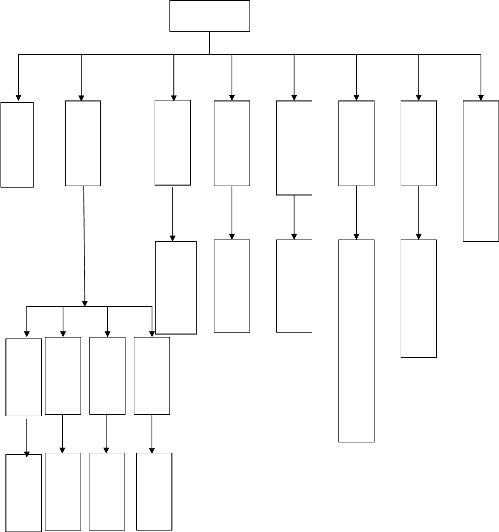
62
Chinese/English Menu Operations
Call List
Off,
1~9
Squelch Level
Menu
Function
Volume Level
Talk Around
Language Select
Channel Display
Chinese/English
Channel Number/Alias/Frequency
Off,
1~5
VOX
Power Select
Backlight
Mode Select
Off/On
Conventional/Trunking
High/Low
Off,
1~5
On/Off/Auto
Signal Strength XXXdBm
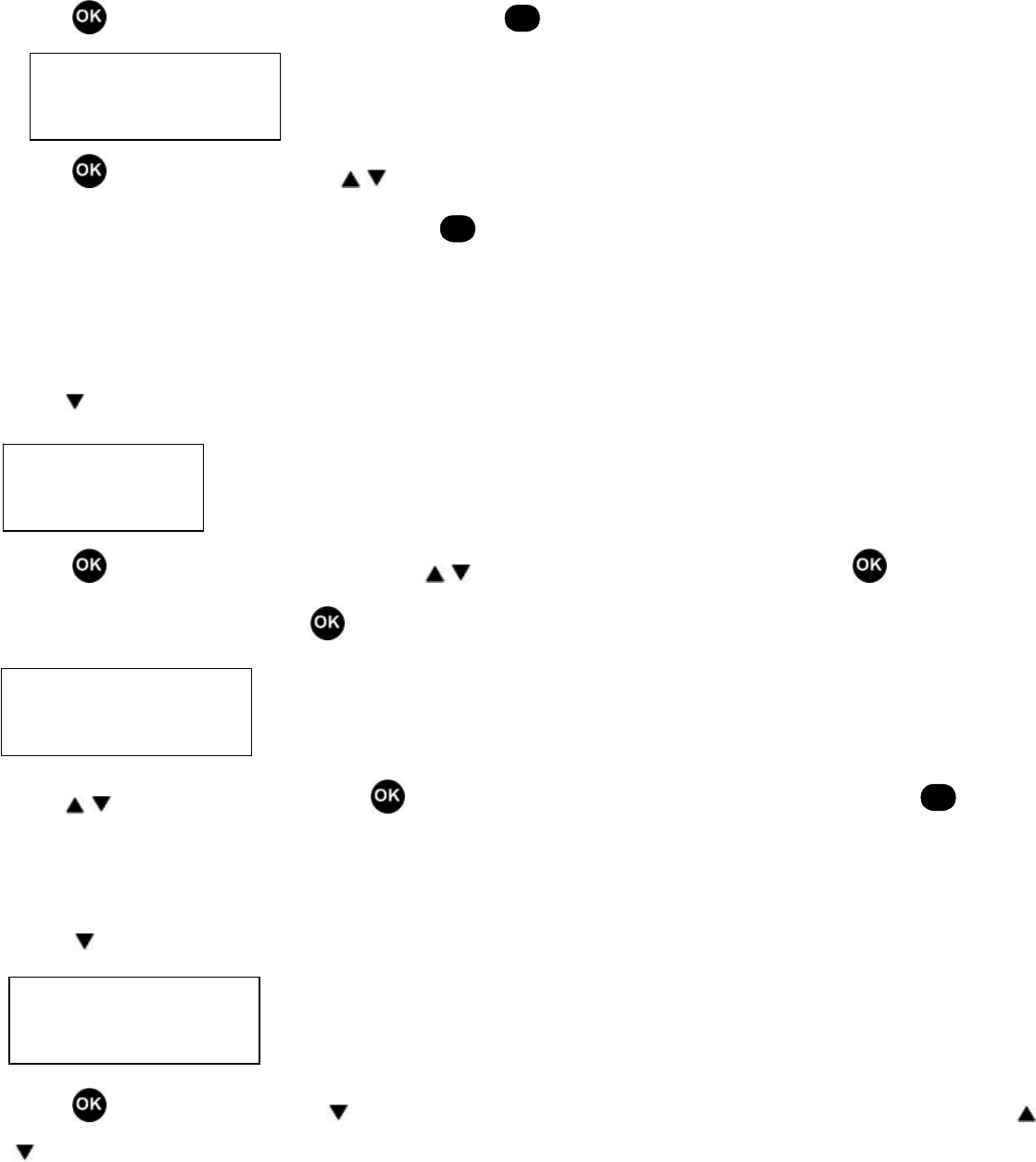
63
Call List
1. Press in standby mode to enter the main menu, or
C
to exit. The radio enters “Call List” first.
2. Press to enter the call list. Press / to select the DTMF ID to be called.
3. Press the PTT key to call and then exit, or press
C
to return to the previous menu.
Function
Backlight
1. Press to select “Function”.
2. Press to enter the function list. Then press / to select the item to be changed and press to enter the item.
To change backlight status, press .
3. Press / to select On/Off/Auto. Press to save the setting and return to the function list, or press
C
to return
to the function list without saving the setting.
Squelch Level
1. Press to select “Function”.
2. Press to enter and then press to select and enter “Squelch”. The current squelch level is displayed. Press /
to select a squelch level (Off, 1~9).
Call List
Function
Function
Backlight
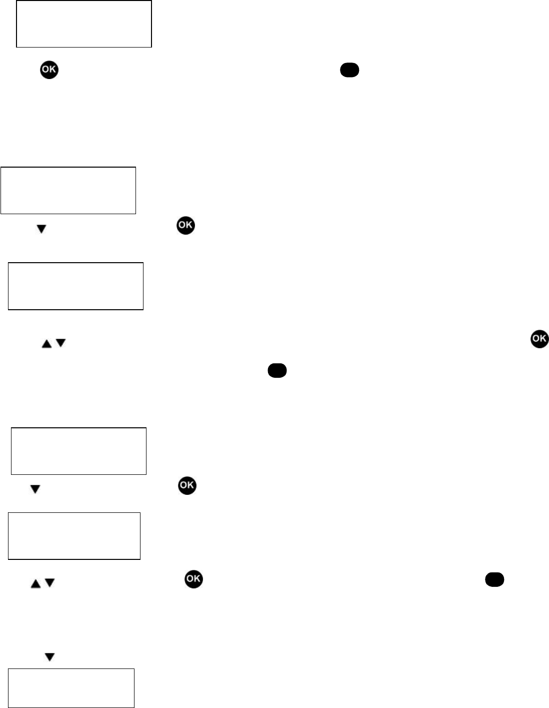
64
3. Press to save the setting and return to the function list, or press
C
to return to the function list without saving
the setting.
VOX
1. Enter “Function”
2. Press to select “VOX” and press to enter. The VOX level is displayed on the LCD.
3. Press / to select a VOX level (Off, 1~5). “Off” on the LCD indicates that the VOX feature is disabled. Press to
save the setting and return to the function list, or press
C
to return to the function list without saving the setting.
Power Select
1. Enter “Function”.
2. Press to select “Power” and press to enter. Power select is displayed on the LCD.
3. Press / to select High/Low. Press to save the setting and return to the function list, or press
C
to return to
the function list without saving the setting.
Volume Level
1. Press to select “Volume Level”.
Squelch Level
Function
VOX
Function
Power Select
Volume Level
65
2. Press to enter. The volume level is displayed on the LCD. Press / to select a volume level (Off, 1~5). Press
to save the setting and return to the main menu, or press
C
to return to the main menu without saving the
setting.
Talk Around
1. Press to select “Talk Around”.
2. Press to enter. The current repeat status is displayed on the LCD. Press / to select On/Off. Press to
save the setting and return to the function list, or press
C
to return to the function list without saving the setting.
Language Select
1. Press to select “Language Select” and to enter. The current language is displayed on the LCD. Press / to
select Chinese/English.
2. Press to save the setting and return to the function list, or
C
to return to the function list without saving the
setting.
Channel Display
1. Press to select “Channel Display”.
2. Press to enter. The current channel display mode is displayed on the LCD. Press / to select Channel
Number/Alias/Frequency. Press to save the setting and return to the function list, or press
C
to return to the
function list without saving the setting.
Mode Select
1. Press to select “Mode Select”.
Talk Around
Language Select
Channel Display
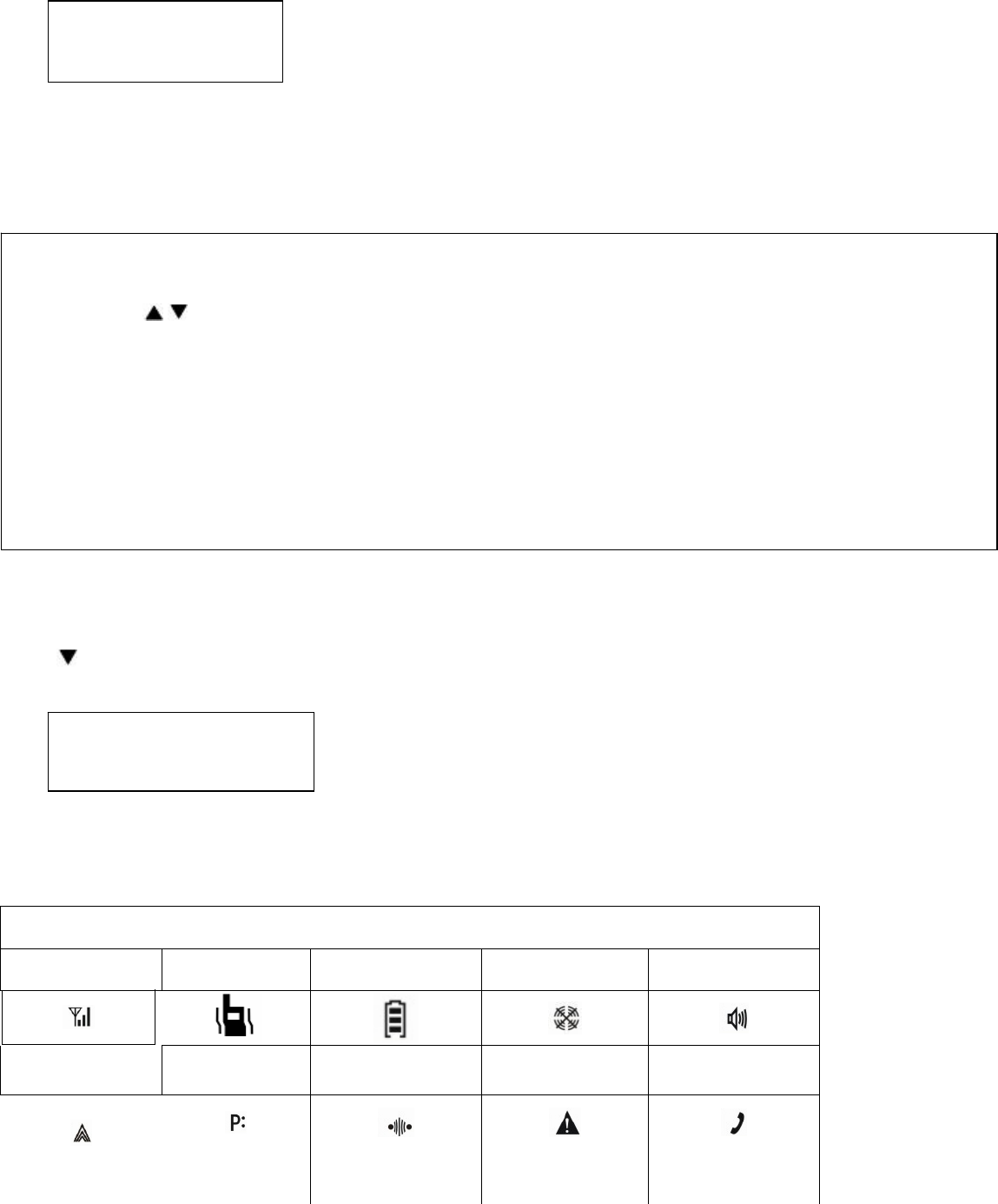
66
2. Select Conventional/Trunking.
3. Conventional: The radio operates with conventional features.
Trunking: The radio operates with trunking features.
Signal Strength
Press to enter “Signal Strength”. The signal strength value of the current channel is displayed.
Appendix 1 LCD Icons
Icons & Indications
Signal Strength Vibrate Battery Strength Transmit Inhibit Monitor/Squelch On
Transmit Power Priority Channel Talk Around Emergency Call
Accessory Interface Short Message
Mode Select
Signal Strength XXXdBm
Note:
1. Press / in the main menu to switch repeatedly according to the above order.
2. During menu operation, if the radio remains at one interface for more than 20 seconds or the Channel Selector
knob is rotated, the radio will return to the standby mode. All values will not be saved. Responses to other keys
are identical with processes in the standby mode.
3. Chinese/English interface.
4. Languages can be changed to others via the programming software and are displayed according to the
programming set.

67
Appendix 2 Keypad Characters
Keypad
0 1 2 3 4 5 6 7 8 9 * #
Troubleshooting
Symptom Solution
Cannot power on the radio.
z The battery runs out. Please recharge the
battery or replace it with a new one.
z The battery is not properly installed.
Please remove the battery and attach it
again.
The operating time is noticeably shorter than
normal.
z The battery has worn out. It is time to buy
a new battery.
Cannot talk to or hear group members. z Make sure that your radio operates on the
same frequency and has the same
CTCSS/CDCSS settings with your group
members.
z Make sure you are within the
communication range.
Hear non-group members z Please change your CTCSS/CDCSS
settings, and so as your group members.
Care and Cleaning
z Do not handle the radio by its antenna or external microphone directly.
z Do not place the radio in a dusty or dirty environment.
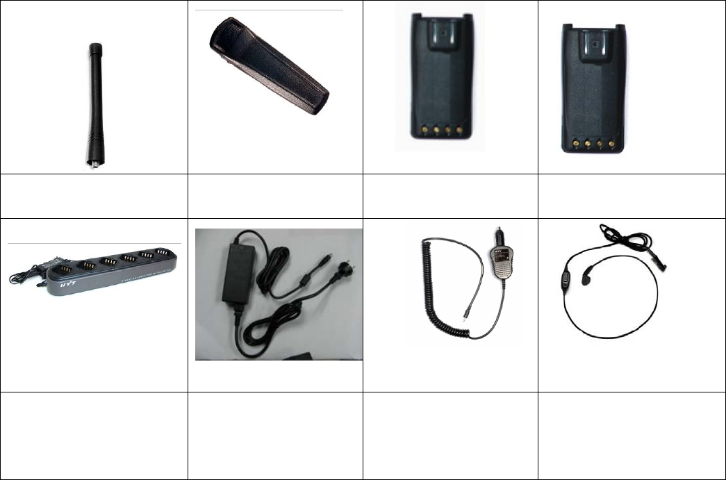
68
z Clean the radio with a lint-free cloth to remove dirt or grease, to avoid poor contact due to excessive dust.
z Clean the radio using a lint-free cloth moistened with clean water and a mild dishwashing liquid.
z Avoid subjecting the radio to corrosives, solvents or spirits.
Optional Accessories
Antenna Belt Clip BC09 Ni-MH Battery (1800mAh)
BH1801
Li-Ion Battery (2100mAh)
BL2102
MCU Multi-unit Charger (for
Li-Ion/Ni-MH batteries) MCA03
Switching Power PS7501
(for use with different power
cords for different countries
and areas)
Vehicle Adapter CHV09 Earbud with in-Line PTT
ESN05
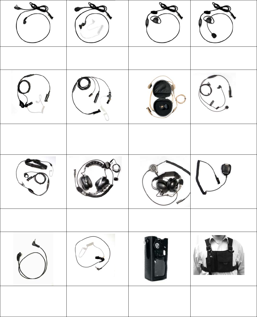
69
Earbud with on-MIC PTT
ESN06
Earpiece with on-MIC PTT &
Transparent Acoustic Tube
EAN04
D-earset with in-Line
Microphone & PTT EHN07
D-earset with Boom
Microphone & in-Line PTT
EHN08
2-Wire Surveillance Earpiece
with Transparent Acoustic
Tube (beige/black)
EAN05/EAN07
3-Wire Surveillance
Earpiece with Transparent
Acoustic Tube (beige/black)
EAN06/EAN02
2-Wire Earpiece with
Wireless Earphone and
Neck Loop (beige) EWN03
Bone Induction Earpiece with
in-Line PTT EBN01
Light-weight, Throat-Vibrating
Earpiece with in-Line PTT
ELN02
Heavy Duty,
Noise-Cancelling Headset
ECN08
Behind-the-Head,
Noise-Cancelling Headset
ECN09
Remote Speaker Microphone
SM08N1
Receive-only Earpiece (for use
with remote speaker
microphone) ESS07
Receive-only Earpiece with
Transparent Acoustic Tube
(for use with remote speaker
microphone) ESS08
Leather Carrying Case
(swivel) (for keypad and
display models) LCBY22
Chest Pack LCBN13

70
Programming Cable (COM
port) PC18
Programming Cable (USB
port) PC25
HYT endeavors to achieve the accuracy and completeness of this manual, but no warranty of accuracy or reliability is given.
All the above specifications and design are subject to change without notice due to continuous development.
No part of this manual may be copied, reproduced, translated, stored in a retrieval system, distributed, or transmitted in any
form or by any means, electronic or mechanical, for any purpose without the express written permission of HYT.