HYT Science and Technology Co TM-610U1 Mobile Radio User Manual
Shenzhen HYT Science &Technology; Co Ltd Mobile Radio
UserManual.wiki
>
HYT Science and Technology Co
>
TM 610U1 User Manual
Users Manual
Navigation menu
Upload a User Manual
Namespaces
Wiki Guide
HTML
PDF
Info
Views
User Manual
Discussion / Help
Navigation
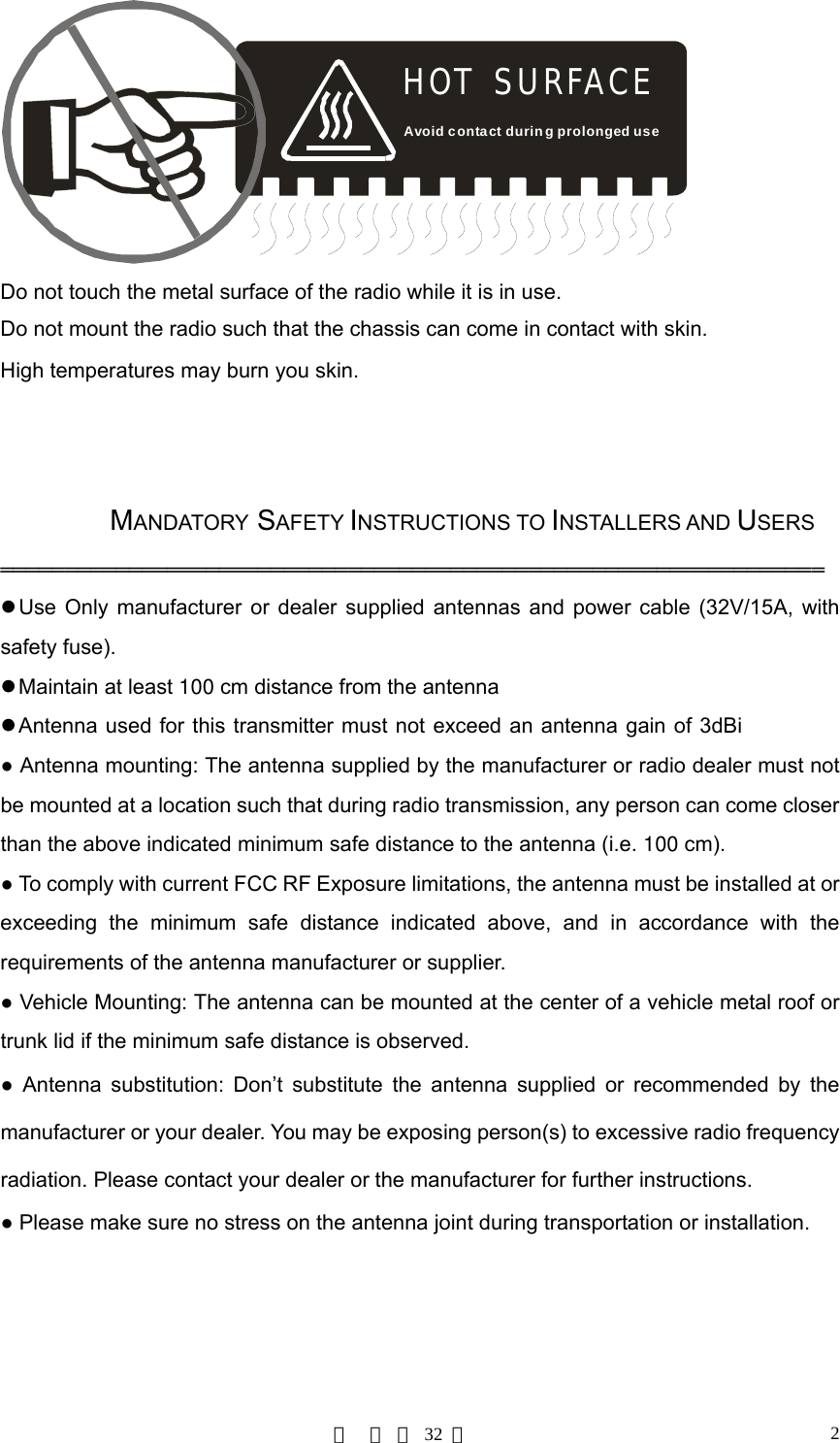
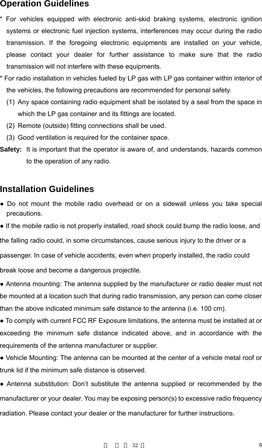
![第 页 共 32 页 6Product Safety and RF Exposure Compliance Your HYT mobile radio is designed and tested to comply with a number of national and international standards and guidelines (listed below) regarding human exposure to radio frequency electromagnetic energy. This radio complies with the IEEE and ICNIRP exposure limits for occupational/controlled RF exposure environment at operating duty factors of up to 50% transmitting and is authorized by the FCC for occupational use only. In terms of measuring RF energy for compliance with the FCC exposure guidelines, your radio radiates measurable RF energy only while it is transmitting (during talking), not when it is receiving (listening) or in standby mode. Your HYT mobile radio complies with the following of RF energy exposure standards and guidelines z United States Federal Communications Commission, Code of Federal Regulations; 47CFR part 2 sub-part J z American National Standards Institute (ANSI)/Institute of Electrical and Electronic Engineers (IEEE) C95. 1-1992 z Institute of Electrical and Electronic Engineers (IEEE) C95. 1-1999 Edition z International Commission on Non-Ionizing Radiation Protection (ICNIRP) 1998 Operational Instructions and Training Guidelines To ensure optimal performance and compliance with the occupational/controlled environment RF energy exposure limits in the above standards and guidelines, users should transmit no more than 50% of the time and always adhere to the following procedures: Transmit and Receive To transmit (talk), push the Push-To-Talk ([PTT]) key; to receive, release the [PTT] key.](https://usermanual.wiki/HYT-Science-and-Technology-Co/TM-610U1/User-Guide-743264-Page-6.png)
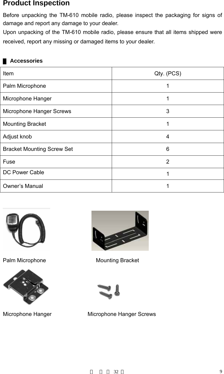
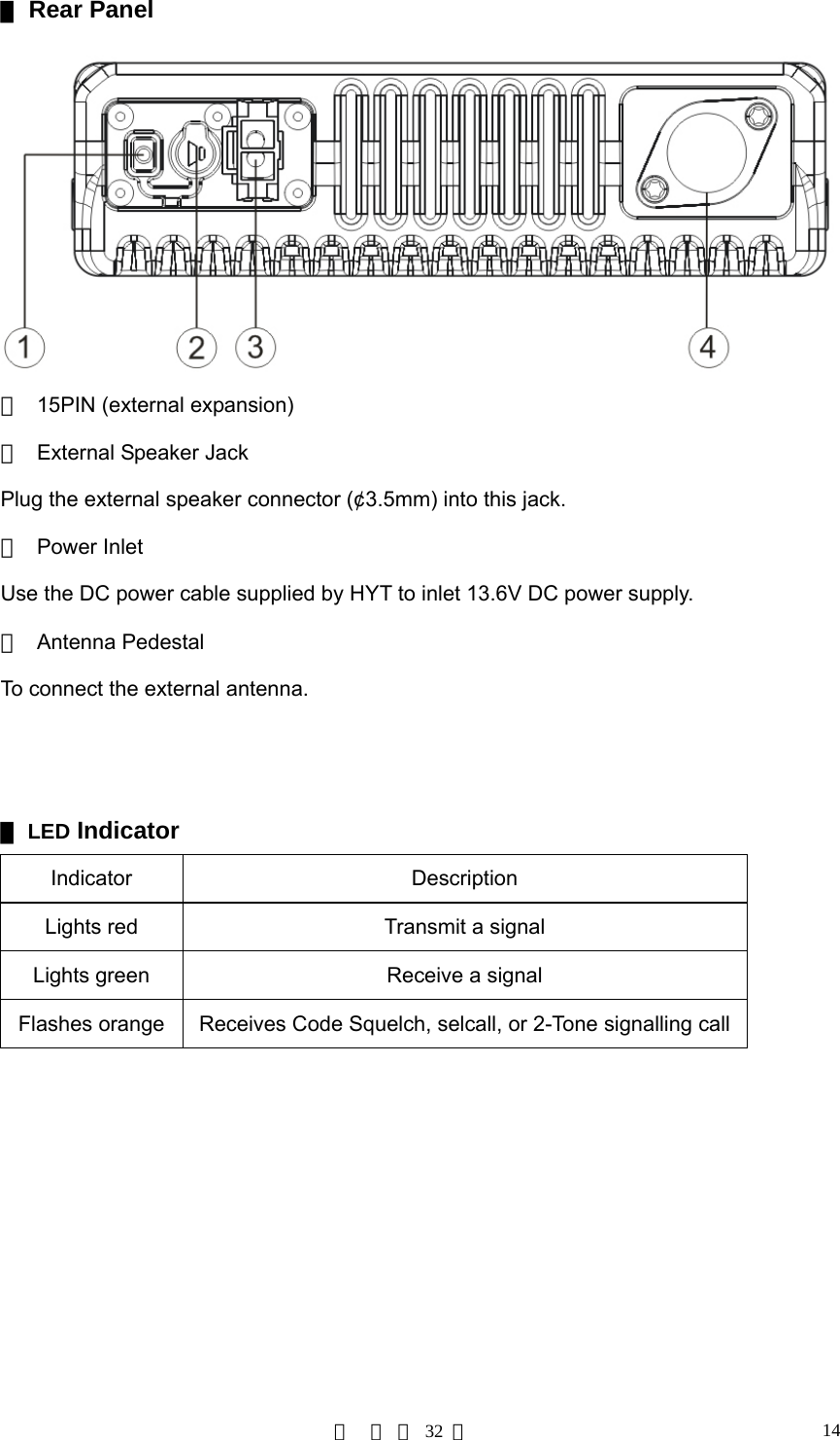
![第 页 共 32 页 13Radio Overview ▇Front Panel ① Volume Control Knob Turn the Volume Control Knob clockwise to increase the volume, or counter-clockwise to decrease the volume. ② LCD Please refer to the “LCD Display” section for details. ③ Programmable Functions Keys ([▲] / [▼]) The [▲] / [▼] keys are programmable with auxiliary functions by your dealer. Please refer to the “Programmable Functions Keys” section. ④ LED Indicator ⑤ Speaker ⑥ Power Switch ⑦ Programmable Functions Keys ([P1]/[P2]/[P3]/[P4]) The [P1]/[P2]/[P3]/[P4] keys are programmable with auxiliary functions by your dealer. Please refer to the “Programmable Functions Keys” section. ⑧ Mic Jack Plug the microphone connector into this jack.](https://usermanual.wiki/HYT-Science-and-Technology-Co/TM-610U1/User-Guide-743264-Page-13.png)
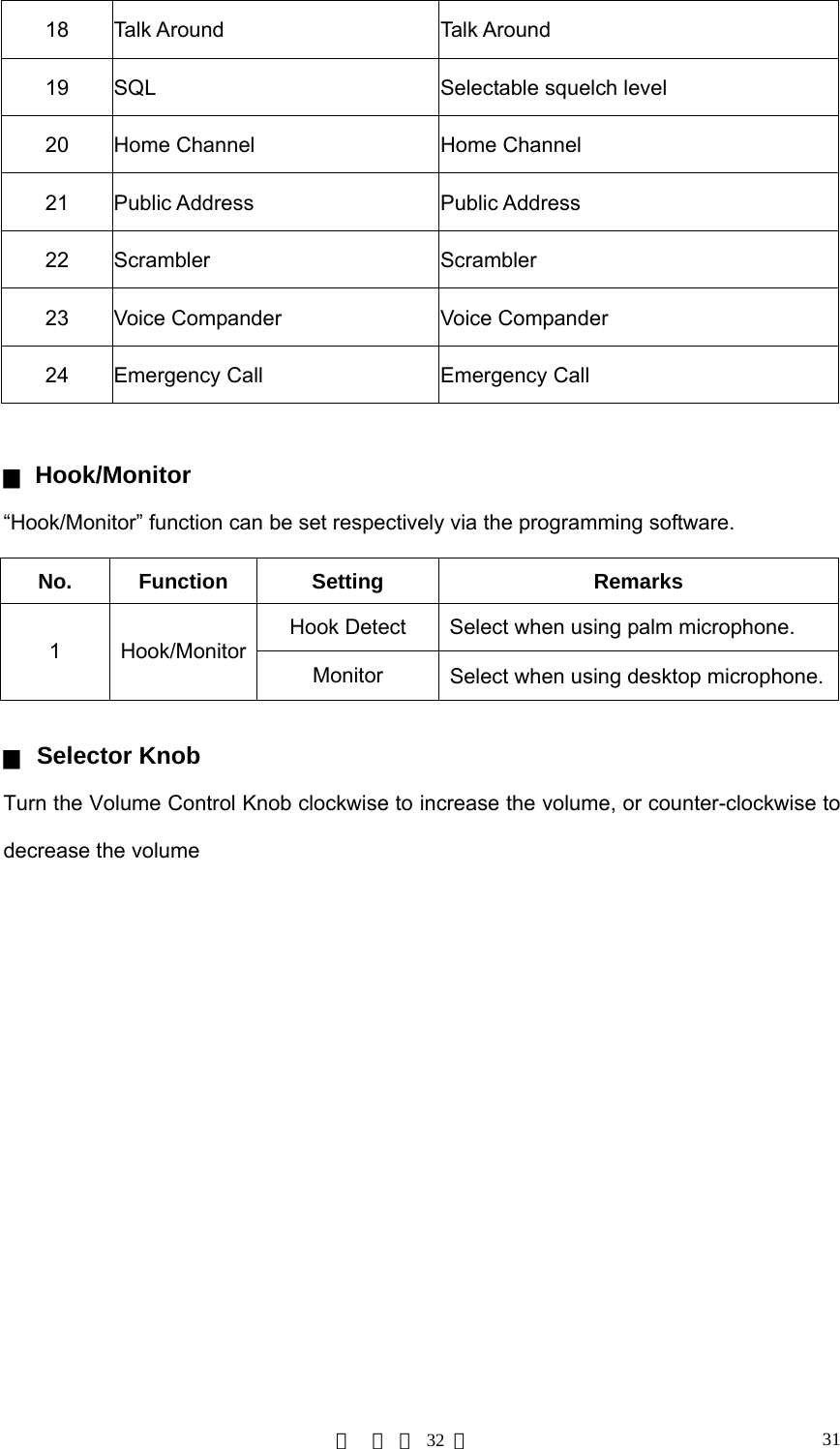
![第 页 共 32 页 15 ▇Programmable Function Keys The [P1]-[P4], [▲]/ [▼] keys are programmable with auxiliary functions as follows: 1. Off 2. CH Up 3. CH Down 4. Zone Up 5. Zone Down 6. Monitor A 7. Monitor B 8. Monitor C 9. Monitor D 10. Display Frequency 11. Display Mode 12. User Selectable CTCSS/CDCSS (UST) 13. 2-Tone Encode Select 14. TX Power Select 15. Scan 16. Scan Add/Delete 17. Reverse Frequency 18. Talk Around 19. Select Squelch Level 20. Home Channel 21. Public Address 22. Scrambler 23. Voice Compander 24. Emergency Call](https://usermanual.wiki/HYT-Science-and-Technology-Co/TM-610U1/User-Guide-743264-Page-15.png)
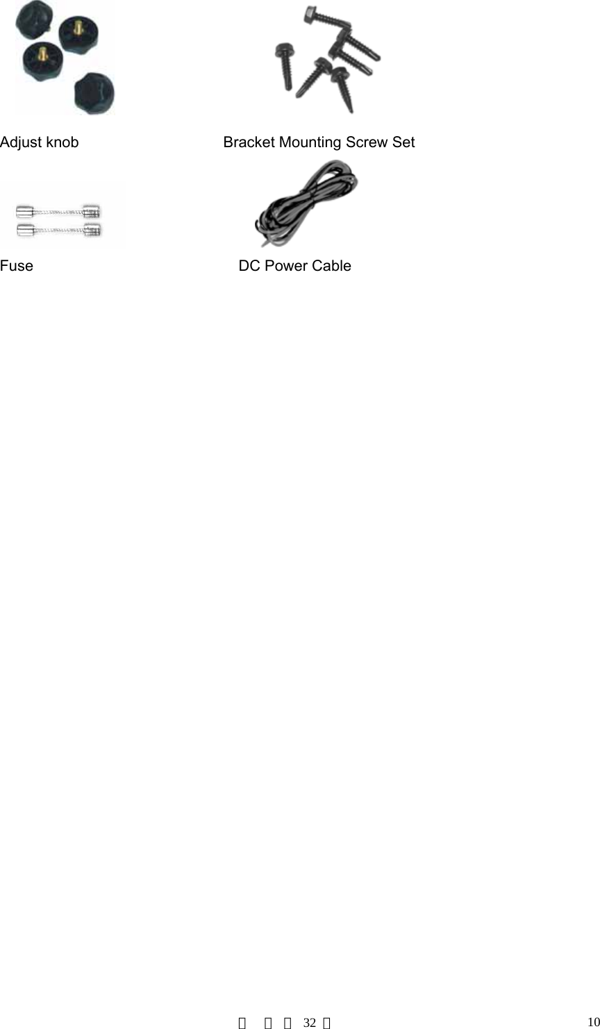
![第 页 共 32 页 16 ▇LCD Display Figure 1 LCD panel Indicator Description Displays CH number/name, zone number/name, DTMF number, frequency, menu and options, etc. Lo Low power output. Press the [Monitor] key: 1. The “ ” icon is displayed when CTCSS/CDCSS, 2-Tone decoding is off. 2. The “ ” icon is displayed when speaker is unmuted. Appears when activity is detected on non-priority channel during the Scan status. Appears when transmitting a selective call. C indicates that the current channel is within the scan sequence. Z indicates multi zone scan. The scrambler feature is enabled. The voice compander feature is enabled. The current channel is already in use. Indicates the current channel is the priority channel. P• indicates priority channel 1, P. indicates priority channel 2, P: indicates priority channel 1 and 2.](https://usermanual.wiki/HYT-Science-and-Technology-Co/TM-610U1/User-Guide-743264-Page-16.png)
![第 页 共 32 页 17Basic Operations Turn Radio On/Off Press the power switch to turn on the radio. Press and hold down the power switch for about 1 second to turn off the radio. Adjust the Volume Turn the Volume Control Knob clockwise to increase the volume, or counter-clockwise to decrease the volume. During adjusting, please note that if the radio is programmed with CTCSS/CDCSS or 2-Tone signalling squelch, noise will not be heard from local speaker even though you turn the volume control knob fully clockwise. Monitor If the Monitor function is set by your dealer, press the programmed Monitor key while in receive mode, to hear activities on the current channel. The Monitor key is programmable with one of the following four operating modes by your dealer: 1. Carrier Squelch-Momentary Hold down the [MONI] key to open CTCSS/CDCSS/2-Tone signalling squelch. Release to close the signalling squelch. 2. Carrier Squelch-Toggle Press the [MONI] key to open CTCSS/CDCSS/2-Tone signalling squelch. Press again to close the signalling squelch. 3. Squelch Off-Momentary Hold down the [MONI] key to open carrier squelch; Release to close the carrier squelch. 4. Squelch Off-Toggle Press the [MONI] key to open carrier squelch. Press again to close the carrier squelch. Select a Channel The [▲]/[▼], [P1]-[P4] function keys are programmable by your dealer to select a channel.](https://usermanual.wiki/HYT-Science-and-Technology-Co/TM-610U1/User-Guide-743264-Page-17.png)
![第 页 共 32 页 18The RX/TX frequency on each channel is set by your dealer. Press the [CH Up] key (programmable) to select a higher numbered channel; press the [CH Down] key (programmable) to select a lower numbered channel. Select a Zone The [▲]/[▼], [P1]-[P4] function keys are programmable by your dealer to select a zone. The RX/TX frequency on each channel is set by your dealer. Press the programmed [Zone Up] key to select a higher numbered zone; press the programmed [Zone Down] key to select a lower numbered zone. Receive a Call If CTCSS/CDCSS, 2-Tone is set on the current channel by your dealer, you can receive calls with matched signalling only. If CTCSS/CDCSS, 2-Tone is not set, you can hear from all the users on the same channel. Send a Call 1. Hold down the [PTT]. 2. Speak into the microphone. The red LED lights while calling. 3. Release the [PTT] to return to the receive mode. 4. When transmission ends, put the microphone on hook. Select Power Level If the current channel is programmed with high power by your dealer, the power output toggles between high and low upon each press the programmed Tx Power Select key. The “LO” icon is displayed on LCD while using low power. A higher level means you can reach a radio that is farther away. A lower power level saves battery and reduces the possibility of interference. Use the high power setting only when necessary. Note: * If the current channel is programmed with lower power, press the Tx Power Select key](https://usermanual.wiki/HYT-Science-and-Technology-Co/TM-610U1/User-Guide-743264-Page-18.png)
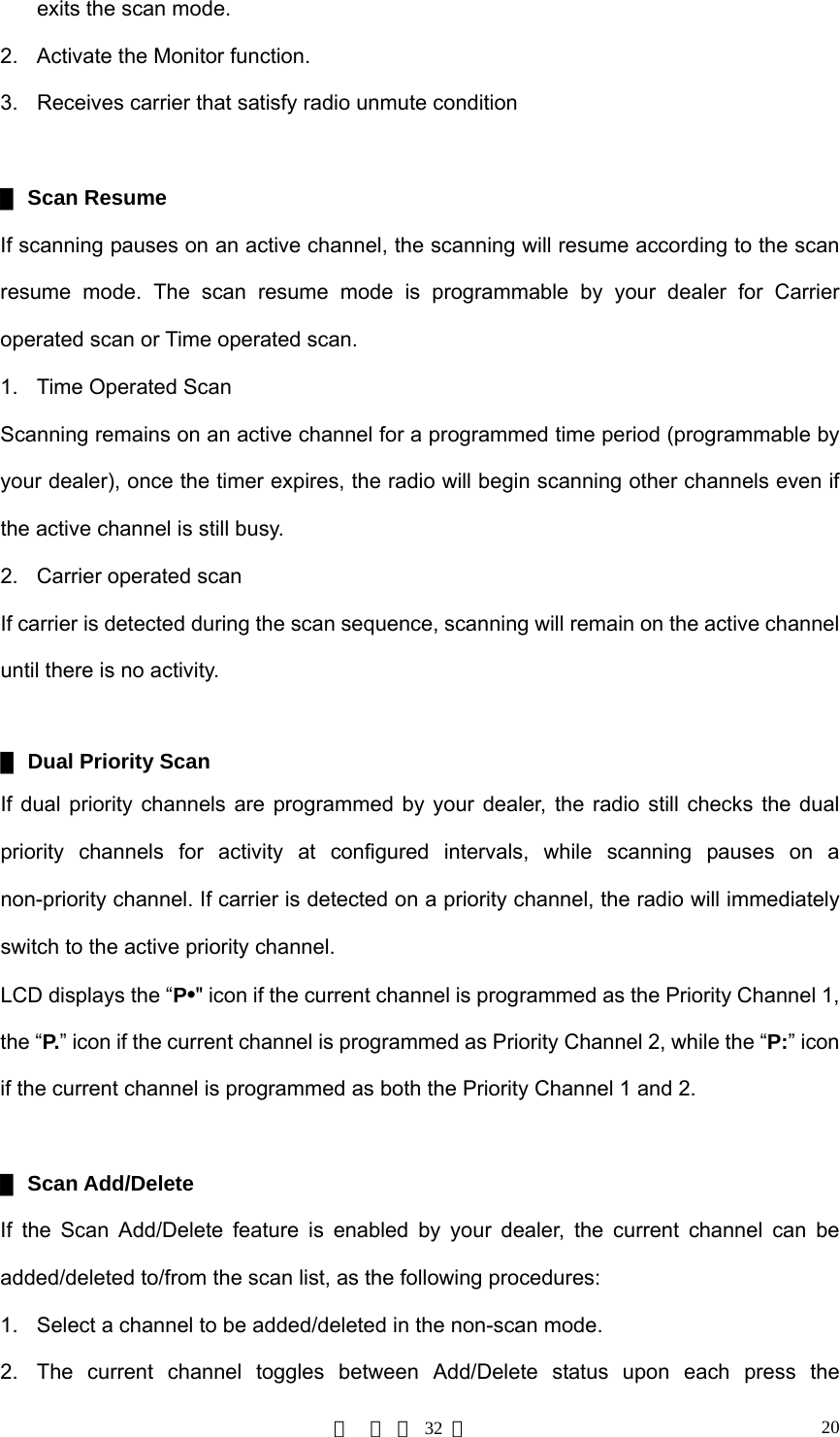
![第 页 共 32 页 19prompts an error tone, and the power level will not change. * If you switch to low power on a channel that was set with high power, this configuration is done on all other channels that were set with high power. BOT ID and EOT ID Your dealer may configure whether to transmit Connect ID (BOT ID) and Disconnect ID (EOT ID), when connecting or disconnecting a repeater or telephone system. The following modes are programmable: 1. BOT ID occurs on each press of [PTT]. EOT ID occurs on each release of [PTT]. 2. Press the [*] while holding down the [PTT], then BOT ID is transmitted. Pres the [#] while holding down the [PTT], then EOT ID is transmitted. Scan ▇Scan Type 1. Single Zone Scan Radio scans all the channels that added into the scan list on the current zone. 2. Multi Zone Scan Multiple zones that added into a multi scan list can be scanned. All channels within all the zones that added into the scan list can be scanned. ▇Scan Start 1. Add one or several non-priority channels into the scan list. 2. Press the programmed Channel Scan key to initiate scan from the current channel, and ascends through the channel numbers in scan list. The LCD displays the “SCAN” icon (“-SCAN-” indicates multi zone scan). ▇Scan Cease Scanning pauses or ceases upon the following: 1. Upon repress the programmed Channel Scan key, scanning ceases, and the radio](https://usermanual.wiki/HYT-Science-and-Technology-Co/TM-610U1/User-Guide-743264-Page-19.png)
![第 页 共 32 页 21programmed Scan Add/Delete key. Note: Only channels that added into the scan list can be scanned. ▇Nuisance Channel Delete Temporarily deletes a specific channel from your scan list during the scan sequence. When scan pauses on an unwanted channel such as a noise channel, press the programmed Add/Del Scan key to temporarily deleted the channel from the scan list, then scanning reinitiates immediately. Note: the temporary delete is not memorized once radio exits from the scan mode. ▇Revert Channel Upon pressing the [PTT] during scanning, the radio will pause scanning and switch to the Revert Channel to transmit. This feature is programmable by your dealer. ▇Off-Hook Scan If the feature is enabled by your dealer, radio scans no matter the microphone is in the off or on hook condition. Otherwise, microphone must be on hook for scanning. Busy Channel Lockout (BCL) The feature can be enabled/disabled by your dealer, this feature is to prevent transmission on a channel that is already in use. Press the [PTT] on a channel that is already in use, transmission is inhibited and an alert tone is heard. Upon release the [PTT], the alert tone ceases and radio returns to receive mode. Press the [PTT] to transmit while the channel is free. BCL Override If the BCL Override feature is enabled, you can override the BCL feature to transmit on a busy channel. Press the [PTT], a BCL alarm will be heard, then repress the [PTT] within 0.5s to override the BCL feature and transmit on the busy channel.](https://usermanual.wiki/HYT-Science-and-Technology-Co/TM-610U1/User-Guide-743264-Page-21.png)
![第 页 共 32 页 22DTMF Call ▇Manual Dial Press any key from the DTMF keypad of the microphone, while holding down the [[PTT]], to transmit the DTMF frequency, and the DTMF tone will be heard from the local speaker. Release the [[PTT]] to remain transmission for 2s (programmable by your dealer), press a numeric key within the 2s to continue transmission. ▇Keypad Auto [PTT] If the feature is enabled by your dealer, press numeric key to transmit DTMF frequency without pressing the [[PTT]]. ▇Store & Send When the feature enabled, enter a pre-stored DTMF number (up to 16 digits) in receive mode, then press the [PTT] on the microphone to initiate a call, simultaneously, the dialed DTMF number scrolls across the LCD, and the corresponding DTMF tone is heard. Note: * If you dialed a wrong number or you want to cancel the dialing, you just simply press any key on the front panel other than the power switch to exit. * The “D” character can be programmed by your dealer as a blank tone, that is, the “D” tone will not be heard while transmitting, but only a delay. The delay time of the “D” character is programmable by your dealer. ▇DTMF Speed 6, 8, 10 or 15 digits per second is programmable by your dealer. The feature is designed to reduce false decode by providing a fixed interval time between digits. Default: 10 digits per second. ▇Store DTMF Numbers Allows you to store a DTMF number (up to 16 digits) in each of the 32 Auto Dial memory (01~32) respectively, detailed as follows:](https://usermanual.wiki/HYT-Science-and-Technology-Co/TM-610U1/User-Guide-743264-Page-22.png)
![第 页 共 32 页 231. Press the [#] key on the microphone keypad, then the LCD displays “D ------”. 2. Enter the desired number (range from 0~9, A~F) via the microphone keypad. If you want to enter A, B, C, D, E, F, please enter 2, 5, 8, 0, *, # respectively while holding down the [PTT]. 3. Press the [#] key, the “ --” is displayed following the “D” character, indicating the location of the memory number. 4. Enter the desired memory number (01~32). 5. Press again the [#] key on the microphone keypad, then the entered number is stored into the corresponding memory. If you dialed a wrong number or you want to cancel the dialing, please press any key on the front panel other than the power switch to exit. ▇Confirm the Stored DTMF Numbers 1. Press the [*] key on the microphone keypad, then the LCD displays “A --”. 2. Enter the memory number (01~32), the LCD displays the stored number or its alias. 3. Press any key other than the [PTT], the LCD resumes the initial display. ▇Auto Dial 1. Press the [*] key on the microphone keypad, then the LCD displays “A --”. 2. Enter the memory number (01~32), the LCD displays the stored number or its alias. 3. Press the [PTT], then the number is transmitted. ▇Clear Stored DTMF Numbers 1. Press the [#] key on the microphone keypad, then the LCD displays “D ------”. 2. Press again the [#] key on the microphone keypad, then the LCD displays “Clear --”. 3. Enter the memory number that to be cleared (01~32). To cancel this operation, please press any key other than 0~9. 4. Press the [#] key on the microphone keypad, then the stored number is cleared. ▇Redial 1. Press the [*] key on the microphone keypad, the LCD displays “A --”.](https://usermanual.wiki/HYT-Science-and-Technology-Co/TM-610U1/User-Guide-743264-Page-23.png)
![第 页 共 32 页 242. Press the [0] key twice, then the last dialed number (up to 16 digits) is dialed and displayed on LCD. 3. Press the [PTT], the number is transmitted. Note: The redial memory is cleared once radio power off. Code Squelch This feature can be enabled/disabled by your dealer. If the feature is enabled, the preset 2-Tone controls radio mute/unmute. The radio will not unmute until matched signalling is received. ▇Receive 1. Radio is unmuted when matched 2-Tone signalling (programmed by your dealer) is received, the user can hear from the transmitter without any other operation. 2. The “ ” icon flashes on LCD, and the LED flashes orange. 3. Radio is muted upon press the programmed Monitor key, or no signal is received within the preset time period. 4. If the alert tone is enabled, radio will emits alert tone when match signalling is received. If the Transpond is enabled, radio will transpond a tone to the calling radio. However, radio will not transpond if a group call is received. ▇Transmit 1. Holding down the [PTT] 2. While encoding, the LED lights red. Please refer to the [TTS] key for 2-Tone encoding. 3. Upon release the [PTT], the signalling squelch is disabled, the “ ” icon flashes on LCD, and LED flashes orange. The LED lights green while signal is received, and flash orange if signal off. 4. If the programmed [Monitor] key is pressed, or no signal is received within the preset time period, the signalling squelch is enabled.](https://usermanual.wiki/HYT-Science-and-Technology-Co/TM-610U1/User-Guide-743264-Page-24.png)
![第 页 共 32 页 25Off Hook Decode If the feature is enabled by your dealer, CTCSS/CDCSS signalling is active no matter the microphone is in the off/on hook condition. If the feature is disabled, CTCSS/CDCSS signalling is disabled while the microphone is in the off hook condition. Time-out Timer (TOT) ▇ Time-out Timer(TOT) The feature allows for more efficient use of channels by limiting the amount of time of each transmission. It protects the radio from damage caused by long time transmission. Once a continuous transmission exceeds the preset time (15~1200s programmable), the transmission is automatically terminated and alert tone is heard. The alert tone ceases upon release the [PTT]. The TOT default is 180s, it meets normal operation needs. Any change should be permitted by professional technicians. ▇ TOT Pre-alert The radio has a TOT Pre-alert timer. The radio will emit the Pre-alert tone at the programmed time (1~10s before the TOT timer expires). ▇ TOT Re-key Time The radio has a TOT Re-key timer. Since transmission is terminated upon the TOT timer expires, the TOT Re-key timer is activated, and transmission is inhibited if press the [PTT] before the expiration of TOT Re-key timer (programmable by your dealer as Off, 1~60s). ▇ TOT Reset Time The TOT Reset timer is activated upon release the [PTT]. While the TOT timer will not reset until the TOT Reset timer expires. Press the [PTT] before the TOT Reset timer expires, the TOT timer continues to countdown. The TOT Reset Time is programmable by your dealer as Off, 1~15s. Emergency Call Holding down the Emergency Call key (programmable as long or short press), the radio](https://usermanual.wiki/HYT-Science-and-Technology-Co/TM-610U1/User-Guide-743264-Page-25.png)
![第 页 共 32 页 26will enter the Emergency Call mode and switch to the preset Emergency Zone/Channel. The radio will firstly transmit within the preset time period, and then receive within the preset time period, and so does the cycle. The radio will back to the channel before the Emergency Call mode, upon re-holding down the Emergency Call key (programmable as long or short press). Programmable Auxiliary Functions The [P1]-[P4], [▲]/ [▼] keys are respectively programmable with one of the following auxiliary functions by your dealer. Reverse Frequency If communications between radios are disrupted because of a long distance from the repeater, the Reverse Frequency function can be used to re-establish communications with another radio. When the function is activated, the transmit frequency and receive frequency will be reversed. The preset CTCSS/CDCSS encode and decode will also be reversed. Press the programmed Reverse Frequency key to toggle the Reverse Frequency function ON or OFF. Enabled Disabled Talk Around If the Talk Around feature is enabled, the Rx frequency is used in place of the Tx frequency when transmitting, and the CTCSS/CDCSS decoding signal is used in place of the encoding signal when encoding. Press the programmed Talk Around key to toggle the Talk Around function ON or OFF. Enabled Disabled](https://usermanual.wiki/HYT-Science-and-Technology-Co/TM-610U1/User-Guide-743264-Page-26.png)
![第 页 共 32 页 27Selectable Squelch Level (SQL) 1. Upon press the programmed SQL key, LCD displays the current squelch level as the following figure: 2. Select the desired squelch level via the programmable function key [▲]/ [▼]. 3. Pressing any key from [P1]-[P4] to save the selected squelch level. The LCD resumes its initial display. Note: High squelch level may cause the radio to ignore weak signals; while low squelch level may cause noise or unwanted signals to be heard. User Selectable CTCSS/CDCSS (UST) If the UST feature is enabled by your dealer, the user can temporarily change the CTCSS/CDCSS codes that preset on the current channel. Operations are as follows: 1. Select a desired channel. 2. Press the programmed UST key to enter the UST mode. 3. Use the [▲]/[▼] keys to select from the preset UST codes (the newly selected CTCSS/CDCSS code is valid in the UST mode only), then the CTCSS/CDCSS code on the current channel is set as the selected UST code. 4. Repress the UST key to exit the UST mode, then the LCD resumes its initial display. Note: This configuration is automatically memorized if the UST BackUp function is enabled, or else, it will not be memorized once switching channel or power off. Public Address (PA) The PA feature amplifies audio inputted from the microphone, and the audio can be heard from the external speaker. 1. Press programmed PA key to activate the PA feature, then the LCD displays “PA”. Repress the PA key to disable the PA feature, then the radio returns to normal user mode. 2. Once the PA feature is activated, the radio is unable to transmit and receive.](https://usermanual.wiki/HYT-Science-and-Technology-Co/TM-610U1/User-Guide-743264-Page-27.png)
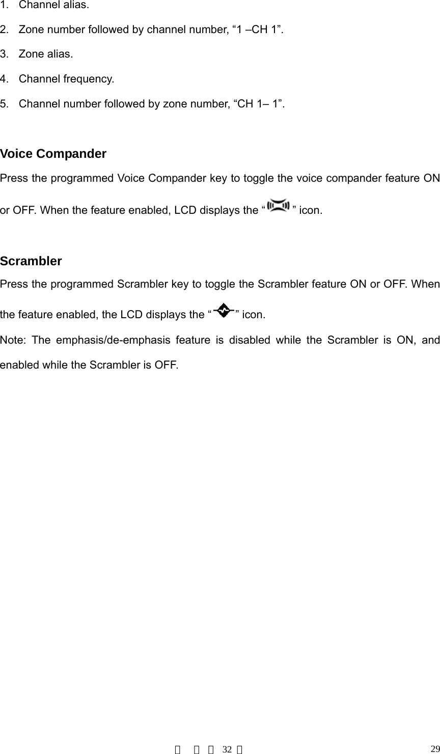
![第 页 共 32 页 283. Speak into the microphone while holding down the [PTT], the PA process initiates, and the LCD displays “PA ON”. While in PA mode or the PA process initiates, you can adjust the volume via the volume control knob. 4. Release the [PTT] to end PA process, then the radio returns to the PA mode, and the LCD displays “PA”. Note: While using the PA system, the optional PA accessories and external speaker must be installed by your dealer. Home Channel Upon press the programmed Home Channel key, the radio will promptly go to the programmed home channel. When dual home channels are set, press the programmed Home Channel key to promptly go to Home Channel 1, press again to promptly go to Home Channel 2, and press for the third time to return to the original channel. 2-Tone Encode Select (TTS) 1. Press the programmed TTS key, the LCD displays the preset 2-Tone number or alias. The LCD scrolls the alias if it exceeds 8 digits. 2. Press the [▲]/ [▼] key to select 2-Tone number (01~32) or alias. 3. Holding down the [PTT] to transmit the selected code. 4. Upon release the [PTT], the signalling squelch is disabled and LED flashes orange. The LED lights green when signal is received, and flashes orange if signal off. 5. If the programmed Monitor key is pressed, or no signal is received within the preset time period, the signalling squelch is enabled. Display Frequency Upon press the programmed Display Frequency key, the LCD displays the frequency of the current channel. Display Mode Upon press the programmed Display Mode key, the radio toggles among the following 5 display modes:](https://usermanual.wiki/HYT-Science-and-Technology-Co/TM-610U1/User-Guide-743264-Page-28.png)
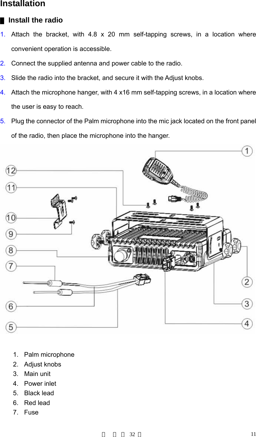
![第 页 共 32 页 30Key Assignment ▇ Programmable Function Keys [P1]-[P4], [▲]/ [▼] are programmable Function keys. Key Assignment No. Function Options Remarks 1 Off No function 2 CH Up ([▲] default) Channel Up 3 CH Down ([▼] default) Channel Down 4 Zone Up ([P3] default) Zone Up 5 Zone Down ([P4] default) Zone Down 6 MONI A Monitor A: Carrier Squelch-Momentary 7 MONI B Monitor B: Carrier Squelch -Toggle 8 MONI C ([P1] default) Monitor C: Squelch Off-Momentary 9 MONI D Monitor D: Squelch Off-Toggle 10 Display Frequency Display frequency of the current channel 11 Display Mode Channel number/channel alias/zone number/zone alias/frequency 12 UST 01-32 (CTCSS/CDCSS) 13 2-Tone Encode Select Select 2-Tone encode 14 TX Power Select Toggle transmit power high/low 15 Scan ([P2] default) Scan status Add/Delete scan channel in non-scan mode 16 Add/Delete Temporarily deletes a noise channel 17 Reverse Frequency Reverse Frequency](https://usermanual.wiki/HYT-Science-and-Technology-Co/TM-610U1/User-Guide-743264-Page-30.png)