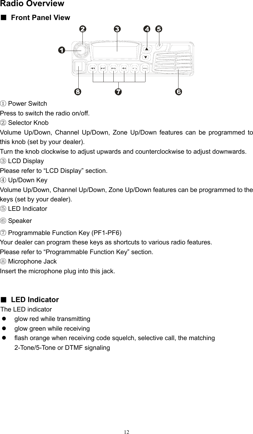
HYT Science and Technology Co TM-800U mobile Radio User Manual TM 800U
Shenzhen HYT Science &Technology; Co Ltd mobile Radio TM 800U
UserManual.wiki
>
HYT Science and Technology Co
>
TM 800U User Manual
users manual
Navigation menu
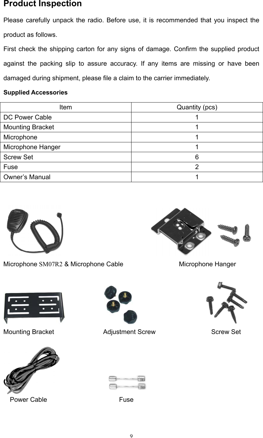
Upload a User Manual
Namespaces
Wiki Guide
HTML
PDF
Info
Views
User Manual
Discussion / Help
Navigation
![13 ■ LCD Display Indicator Description 1. Display zone / channel number. 2. Display zone / channel label (set by your dealer, up to 12 alphanumeric characters). 3. Display channel Frequency 4. Display the preprogrammed functions 1. Display zone / channel number. 2. Display transmit power level (H, M or L). 3. Display the preprogrammed functions Appears when the selected channel is busy. Appears when [MONI] key is pressed to disable CTCSS, CDCSS, DTMF or 2-Tone/5-Tone. Appears when [MONI] key is pressed to switch the speaker on.A 1. Indicate second development feature. 2. Appears when the auxiliary function is activated. SCAN Appears while scanning. CALL Appears when transmitting a selective call. Appears when a new message is received. Appears when the selected zone is in the scan list. Appears when the selected channel is in the scan list.](https://usermanual.wiki/HYT-Science-and-Technology-Co/TM-800U/User-Guide-631488-Page-13.png)
![16 Basic Operations Turn the Radio On/Off Press the Power switch to switch the radio on. Press and hold the Power switch for approximately 1 second to switch the radio off. If Power on Password is set to protect your radio, “Chk P” and the cursor will appear on the display when power is turned on. You can unlock the radio by entering the correct password (8 digits maximum): 1. Select a digit (0-9) by rotating the selector knob. If you are using an optional microphone with a keypad, you can also enter the password by pressing the appropriate keypad keys. 2. Press the [PF3] / [PF4] key to move cursor forward and backward. This step can be skipped when using the keypad. 3. Repeat steps 1 and 2 to enter the entire password. 4. Press the [PF6] key or the [PTT] key to complete the entry. Adjust the Volume Selector Knob, [▲] / [▼] or the function keys PF1-PF6 can be programmed with VOL Up / VOL Down features to adjust volume level. Rotate the Selector Knob clockwise or press the key which be programmed as [VOL Up] key to increase the volume; rotate the knob counter-clockwise or press the key which be programmed as [VOL Down] key to decrease the volume. The current volume level is displayed on the LCD. The LCD returns to original display mode in 5 seconds. Press any key to exit from the volume level display mode. Monitor If monitor feature is set by your dealer, press the key programmed as [MONI] in receive mode to monitor activity on your selected channel. Your dealer can select one of the following four modes for monitor feature: Monitor Unmute-Momentary Hold down the [MONI] key to open CTCSS/CDCSS/DTMF/2-Tone/5-Tone signalling squelch. Release to close the signalling squelch. Monitor Unmute-Toggle Press the [MONI] key to open CTCSS/CDCSS/DTMF/2-Tone/5-Tone signalling squelch. Press again to close the signalling squelch. Carrier Squelch-Momentary Hold down the [MONI] key to open carrier squelch; Release to close the carrier squelch. Carrier Squelch-Toggle Press the [MONI] key to open carrier squelch. Press again to close the carrier squelch. Select a Channel Selector Knob, [▲] / [▼] or the function keys PF1-PF6 can be programmed with CH Up/](https://usermanual.wiki/HYT-Science-and-Technology-Co/TM-800U/User-Guide-631488-Page-16.png)
![17 CH Down features to select a channel. Transmit/Receive frequencies of the channel are set by your dealer. Rotate the Selector Knob clockwise or press the key which be programmed as [CH Up] key to select a channel upwards; Turn the knob counterclockwise or press the key which be programmed as [CH Down] key to select downwards. Select a Zone Selector Knob, [▲] / [▼] or the function keys PF1-PF6 can be programmed with Zone Up/ Zone Down features to select a zone. Transmit/Receive frequencies of the channel are set by your dealer. Rotate the Selector Knob clockwise or press the key which be programmed as [Zone Up] key to select a zone upwards; Turn the knob counterclockwise or press the key which be programmed as [Zone Down] key to select downwards. Receive If your dealer has programmed CTCSS/CDCSS/DTMF/2-Tone/5-Tone signalling on the selected channel, you will hear calls only when the matching code or tone is received; otherwise, all calls on the same channel can be heard. Transmit 1. Press the key programmed as [MONI] to make sure that the selected channel is not in use. 2. Hold down the [PTT] key. 3. Dial a DTMF number using the microphone keypad. Step 3 is not necessary all the time. 4. Speak into the microphone with normal voice. The LED glows red during transmission. 5. Release the [PTT] key to receive. 6. When your conversation is finished, return the microphone to its hanger. Selectable Power Level If transmit power (programmed by your dealer) is set to “high” (or "middle”) on any given channel, press the key programmed as [TX Power] to toggle the TX power among high, middle and low. The current power level is indicated by “H” /“M” / “L” icon on the LCD. Since low power helps to conserve battery power and reduce the risk of interfering with others, you are recommended to select low power when communication quality is guaranteed. Notes: ● Press the [TX Power] key while using a channel programmed with low power, an error tone will sound and the transmit power will not change. ● When changing a channel from high/middle power to low power, all other channels programmed with high/middle power will change to low power accordingly.](https://usermanual.wiki/HYT-Science-and-Technology-Co/TM-800U/User-Guide-631488-Page-17.png)
![18 Beginning/End of Transmission ID Signal The radio can be programmed to send Beginning/End of Transmission ID when accessing / releasing repeaters or telephone systems. The ID signal includes DTMF and 5-Tone types. Two modes can be configured: ● Press the [PTT] key to send a Beginning of Transmission ID Signal; Release the [PTT] key to send an End of Transmission ID Signal. ● Press [*] while holding down the [PTT] key to send a Beginning of Transmission ID Signal; press [#] while holding down the [PTT] key to send an End of Transmission ID Signal (for DTMF type only). Channel Scan ▇ Scan Types ● Single Zone Scan All channels in the current zone that have been added to the scan list can be scanned. ● Multi Zone Scan All channels within all the zones that have been added to the scan list can be scanned. ● List Zone Scan The radio only scans the channels within the specified range of zones that have been added to the scan list. Individually each zone is assigned with a scan list, which provides quick recognition of the zones to be locked out of scan list. Note: Scan list for each zone can be added/ deleted. ▇ Scan Start Press the key programmed as [SCN], scan starts from the current channel and ascends through the channel numbers in scan list. “SCAN” appears on the LCD (“-SCAN X -” in List Zone Scan mode, “X” is the current list number). Note: Scan function can be used only when two or more channels are in the scan list. ▇ Scan Stop 1. Press the [SCN] key again to stop scanning. “SCAN” disappears on the LCD. 2. Activate the Monitor function. 3. Carrier is detected on channels where no signalling is set. 4. Carrier is detected on channels where signalling is set, and the matching signalling is received. ▇ Scan Restart When the radio stops on a busy channel, scanning can be restarted according to the restart mode, which can be programmed by the dealer as carrier-operated scan or time-operated scan. ● Carrier Operated Scan Scanning remains on an active channel until there are no activities; while the channel is free, the radio remains on the channel for the programmed Dropout Delay Time (programmed by your dealer) before it resumes scanning.](https://usermanual.wiki/HYT-Science-and-Technology-Co/TM-800U/User-Guide-631488-Page-18.png)
![19 ● Time Operated Scan Scanning remains on the active channel for only the programmed Dropout Delay Time (programmed by your dealer) before it resumes scanning. After the expiration of Dropout Delay Time, the radio will begin scanning other channels even if the channel is still busy. ▇ Dual Priority Scan If your dealer has programmed dual priority channels, the radio will periodically detect the activity on priority channels while stopping on non-priority channels. When any activity is detected on the priority channels, the radio will switch to the priority channels for communications. “P1” appears on the LCD when the channel is set as Priority 1, “P2” appears when set as Priority2, and “PP” when set as both Priority 1 and Priority 2. ▇ Operator Selectable Priority Channel If priority channel is programmed by your dealer as “Operator Selectable”, you can set the current channel as priority or non-priority channel: Press the key programmed as [MONI] twice while holding down the key programmed as [SCN], the current channel is changed to "Priority 2". Press the [MONI] key three times while holding down the [SCN] key, the current channel is changed to "Priority 1". Press the [MONI] key four times while holding down the [SCN] key, the current channel restores to original setting. ▇ Scan Add/Delete This feature allows you to add/delete a channel to/from the scan list in the non-scan mode. 2. Select the channels to be added/ deleted by using the channel selector knob. 3. Press the key programmed as [Add/Del] to toggle between ADD and DELETE. “”appears on the LCD when a channel is added. Note: The radio only scans the channels that have been added to the scan list. ▇ Look Back Temporary Disable When scanning looks back and stops on a priority channel, press the key programmed as [Add/Del] to deactivate the Look Back function. ▇ Nuisance Channel Temporary Delete This feature allows you to temporarily add/delete a channel to/from the scan list during scanning. When scanning stops on an undesired channel (e.g. nuisance channel), press the key programmed as [Add/Del], the channel is temporarily removed from the scan list and scanning resumes. Note: The addition/ deletion of channels are not saved when radio exits from the scan mode.](https://usermanual.wiki/HYT-Science-and-Technology-Co/TM-800U/User-Guide-631488-Page-19.png)
![20 ▇ Revert Channel Press the [PTT] key during scanning, the radio will stop scanning and switch to the preset revert channel (programmed by your dealer) for transmission. ▇ Off Hook Scan Normally scanning is not controlled by microphone hook status, it also means that the radio always scans, and stops by signal presence. But if your dealer has programmed Off Hook Scan feature, microphone must be on hook for scanning. Busy Channel Lockout (BCL) When activated by your dealer, the BCL feature will prevent you from talking on a channel that is already in use. Press the [PTT] key while the channel is in use, the radio will emit an alert tone and transmission will be inhibited. Release the [PTT] key to stop the alert tone. Wait until the channel is not in use before you try to transmit again. BCL Override If BCL Override feature is activated, you can override the BCL feature and transmit on a busy channel. To override the BCL, release the [PTT] key when the alert tone sounds, then press the [PTT] key again within 0.5 second. DTMF Call ▇ Manual Dial Hold down the [PTT] key, then enter the DTMF number by pressing the keys ([0] ~ [9], [*], [#]) on optional microphone keypad. Audible tone sounds when corresponding DTMF tone is transmitted. The radio can be programmed by your dealer to remain in transmit mode for 2 seconds after releasing the [PTT] key. Press any numeric key within 2 seconds to continue transmission. ▇ Keypad Auto PTT If this feature is programmed by your dealer, you can transmit a DTMF tone by pressing the keys on optional microphone keypad without holding down the [PTT] key. ▇ Store & Send If this feature is activated, enter a preset DTMF number (16 digits maximum) in receive mode, then press the [PTT] key to place the call. The DTMF number scrolls across the LCD display as it is entered, and its corresponding audible tone sounds. Notes: ● If you enter a wrong digit or decide not to dial the number, press any key other than the power switch on the front panel to exit. ● The [D] key can be programmed by your dealer as a null tone. This also means that “D” tone is not transmitted when “D” is entered. Instead, “D” is used for a pause time (programmable by your dealer). ▇ Dial Speed Your dealer can select dial speed at 6, 8, 10 or 15 digits per second. This is designed to reduce false decoder operation by providing a fixed time period](https://usermanual.wiki/HYT-Science-and-Technology-Co/TM-800U/User-Guide-631488-Page-20.png)
![21 between digits. Default: 10 digits per second ▇ Store DTMF Numbers You can store DTMF numbers (16 digits maximum) in each of the 32 Auto Dial memory locations (01~32). 1. Press the [#] key, “D----------” appears on the LCD. 2. Enter the DTMF number (16 digits maximum). You can enter the digits 0-9, A-F. To enter A,B,C,D,E,F, hold down the [PTT] key, then enter 2, 5, 8, 0, *, # respectively. 3. Press the [#] key, “------” appears on the LCD indicating the memory location. 4. Enter the desired memory location number (01~32). 5. Press the [#] key again to store the DTMF number into the memory location. If you enter a wrong digit or decide not to dial the number, press any key other than the power switch on the front panel to exit. ▇ Confirm Stored DTMF Numbers 1. Press the [*] key, “A---” appears on the LCD. 2. Enter the desired memory location number (01~32). The stored DTMF number or caller ID is displayed on the LCD. Press any key other than the [PTT] key, the original display is restored. ▇ Dial Stored DTMF Numbers 1. Press the [*] key, “A---” appears on the LCD. 2. Enter the desired memory location number (01~32). The stored DTMF number or caller ID is displayed on the LCD. 3. Press the [PTT] key to place the call. ▇ Clear Stored DTMF Numbers 1. Press the [#] key, “D----------” appears on the LCD. 2. Press the [#] key again, “D Clear” appears on the LCD. 3. Enter the desired memory location number (01~32). To cancel the process, press any key other than [0]~[9]. 4. Press the [#] key, the stored DTMF number is cleared. ▇ Redial 1. Press the [*] key, “A--” appears on the LCD. 2. Press the [0] key twice, the last number (16 digits maximum) you dialed is redialed. The redialed number is displayed on the LCD. 3. Press the [PTT] key to place the call. Note: The redial memory is cleared when the radio is turned off. Code Squelch The code squelch feature can be programmed by your dealer. If this feature is activated, squelch turns on only when the received DTMF/2-Tone/5-Tone code matches the radio ID code (set by your dealer). Otherwise, your radio will not](https://usermanual.wiki/HYT-Science-and-Technology-Co/TM-800U/User-Guide-631488-Page-21.png)
![22 respond to the calls. ▇ Receive 1. When the received DTMF/2-Tone/5-Tone code matches the radio ID code (set by your dealer), squelch turns on and you will hear the call without any further action after an alert tone/Transpond finishes. 2. “CALL” icon appears on the LCD and radio LED flashes orange. 3. Signalling squelch will turn back ON when you press the key programmed as [MONI] or when no signal is received for the preset time period. 4. The radio can be programmed to sound an alert tone when receiving a matching code. If Transpond for Code Squelch function is enabled, the radio will send a transpond signal (programmed by your dealer) to the calling station when receiving the matching code. The Transpond for Code Squelch function can not be used in Group Call mode. ▇ Transmit 1. Hold down the [PTT] key. 2. Enter the preset DTMF code (ID code of the called radio or group) through the keypad. ● If desired, you can use “store and send” or “speed dial” function to transmit codes. Then operates the mobile radio in the same way as a portable radio. ● During code transmission, “CALL” icon appears on the LCD and radio LED glows red. ● Please refer to the [TTS], [FTS] key for 2-Tone/5-Tone transmission. 3. Release the [PTT] key, signalling squelch will turn OFF and LED flashes orange. Radio LED glows green when a signal is received and flashes orange again when the signal drops out. 4. Signalling squelch will turn back ON when you press the key programmed as [MONI] or when no signal is received for the preset time period. Auto Transpond The Auto Transpond function can be programmed by your dealer to use with the Code Squelch function. When activated, the radio will send a transpond signal when receiving the matching code. Four types of transpond signal can be programmed by your dealer: • Ringing tone • Alert Tone • Transpond code • Alert Tone + Transpond code Press any key to stop the ringing tone. Off-Hook Decode If your dealer has activated the feature, CTCSS/DCS decode signalling will be activated no matter whether the microphone is on-hook. Decode signalling is deactivated during the off hook condition, squelch works as carrier squelch. Time-Out-Timer Time-out-Timer (TOT) feature can be set in each zone.](https://usermanual.wiki/HYT-Science-and-Technology-Co/TM-800U/User-Guide-631488-Page-22.png)
![23 ▇ TOT TOT is used to prevent user from transmitting on the same channel for extended period of time. This also protects the radio from damage caused by long time transmissions. If continuous transmission exceeds the preset time (15-1200 seconds), the transmission will be inhibited and an alert tone will sound. Release the [PTT] key to stop the alert tone. The default TOT time of this mobile radio is 180 seconds, which can meet general user’s need. The modification can only be done with the qualified technician’s permission. ▇ TOT Pre-Alert When this feature is activated, the radio will sound an alert tone at the programmed pre-alert time before TOT expires. TOT will expire when the selected time passes after a "Pre-Alert Tone". Pre-alert time (1-10 seconds before the TOT expiration) is set by your dealer. ▇ TOT Rekey Time When this feature is activated, transmission will remain inhibited until TOT Re-key Time expires, even if you have pressed the [PTT] key. Rekey time (Off, 1-60 seconds ) is set by your dealer. ▇ TOT Reset Time TOT won’t reset even after PTT is released unless the TOT Reset Timer has expired. Reset time (Off, 1-15 seconds ) is set by your dealer. Emergency Call Hold down the key programmed as [Emergency] for longer than a preset time ("Emergency Key Delay Time", programmable by your dealer) to enter emergency call mode. The radio will switch to the preset emergency zone / channel, then transmit and receive for a preset time in turn automatically. While in Emergency mode, switch the power OFF or hold down the key again for longer than a preset time ("Emergency Key Delay Time", programmable by your dealer) to exit Emergency mode . Stun & Revive This feature allows user to enable/disable the transmission/reception over the air by transmitting stun code. Stun code (1-16 digits) is programmable. When receiving the stun code, the radio will enter stun mode. The radio will return to normal mode upon receiving a revive code (stun code + [#]). 3 types of stun are shown as following: ● Inhibit transmission ● Inhibit both transmission and reception ● Kill (inhibit all radio functions)](https://usermanual.wiki/HYT-Science-and-Technology-Co/TM-800U/User-Guide-631488-Page-23.png)
![24 Programmable Auxiliary Functions Your dealer can program the following auxiliary functions to the programmable keys PF1-PF6. Reverse Frequency If communications between radios are disrupted because of a long distance from the repeater, reverse frequency function can be used to re-establish communications to another radio. When the function is activated, the transmit frequency and receive frequency will be reversed. The corresponding CTCSS/DCS encoding and decoding signals will also be reversed. Press the key programmed as [Reverse] to toggle the reverse frequency function ON and OFF. ON OFF Talkaround If Talkaround is programmed, the transmit frequency can be changed to be the same as the receive frequency. The CTCSS/DCS encoding signals also change to be the same as the decoding signals. Press the key programmed as [TA] to toggle the Talkaround function ON and OFF. ON OFF Selectable Squelch Level 1. Press the key programmed as [SEL SQL], the current squelch level is displayed on the LCD as shown below. 2. Turn the Selector Knob to select your desired squelch level. 3. Press any key other than the power switch to save the selected squelch level. The LCD returns to the original display mode. Note: If the squelch level is set too high, you may not efficiently receive weak signals; if the level is set too low, you may hear a constant white noise, a sputtering noise, or unwanted signals. User Selectable Tone (CTCSS/DCS) This function can be programmed by your dealer to temporarily change the preset CTCSS/DCS frequency on a channel.](https://usermanual.wiki/HYT-Science-and-Technology-Co/TM-800U/User-Guide-631488-Page-24.png)
![25 1. Select your desired channel. 2. Press the key programmed as [UST] to enter the UST mode. 3. Use the Selector Knob to select a desired UST code/ name. The selected CTCSS/DCS frequency is valid only in UST mode. 4. Press the [UST] key again, the radio exits from UST mode and the LCD returns to the original display mode. Public Address This function can be used to amplify all the audio from the speaker and output the audio through external speaker. 1. Press the key programmed as [PA] to activate Public Address function. “PA” appears on the LCD display. Press the key again to deactivate this function and return to normal user mode. 2. In PA mode, no transmission and reception occurs. 3. Hold down the [PTT] key and speak into the microphone, your voice can be heard from the external speaker that is connected to the radio. “PA On” appears on the LCD display. 4. Release the [PTT] key, the public address process halts and “PA” appears on the LCD display. Notes: ● In Public Address mode, turn the volume knob to adjust the volume. ● To use this function, the dealer should install public address optional accessory and external speaker. Dual Home Channels Press the key programmed as [Home CH], the radio will go to the programmed home channel. When dual home channels are set, press the key programmed as [Home CH] to switch to Home Channel 1, press again to switch to Home Channel 2, and press for the third time to return to the original channel. Horn Alert 1. Press the key programmed as [HA] to activate Horn Alert function, “HA” appears on the LCD display. 2. The radio’s accessory ports HRI and HRO is connected when receiving calls of the matching 2-Tone/5-Tone/DTMF code from the base station or other radios. 3. Press the [HA] key again to exit from the Horn Alert mode. Note: This function is especially helpful when user is away from the radio. It can be used to control the electronic devices over the air.](https://usermanual.wiki/HYT-Science-and-Technology-Co/TM-800U/User-Guide-631488-Page-25.png)
![26 Selectable Two-Tone Encode 1. Press the key programmed as [TTS], the programmed 2-Tone code or name will be displayed on the LCD. 2. Turn the selector knob to select 2-Tone code (01-32) or name. 3. Hold down the [PTT] key to transmit the selected code. 4. Release the [PTT] key, signalling squelch turns off and radio LED flashes orange. 5. Press the key programmed as [MONI], signalling squelch turns back on. Note: The radio will opens signalling squelch automatically if no signal is received for the preset period of time. Selectable Five-Tone Encode 1. Press the key programmed as [FTS], the programmed 5-Tone code or name will be displayed on the LCD. 2. Turn the selector knob to select 5-Tone code (01-32) or name. 3. Hold down the [PTT] key to transmit the selected code. 4. Release the [PTT] key, signalling squelch turns off and radio LED flashes orange. 5. Press the key programmed as [MONI], signalling squelch turns back on. Note: The radio will opens signalling squelch automatically if no signal is received for the preset period of time. Display Frequency Press the key programmed as [DFreq], LCD will display the frequency of the current channel. Display Label Press the key programmed as [DLabel], LCD will display channel label. Display Mode The radio will toggle among the 5 display modes each time when the key programmed as [DMode] is pressed. 5 display modes are shown as follows: Channel number Channel label Zone number Zone label Channel frequency LCD Backlight Press the key programmed as [LCD Backlight] to toggle LCD backlight on/off Compander Press the key programmed as [Compander] to toggle Compander on/off.](https://usermanual.wiki/HYT-Science-and-Technology-Co/TM-800U/User-Guide-631488-Page-26.png)
![27 Scrambler Press the key programmed as [Scrambler] to toggle Scrambler on/off. Note: Emphasis/de-emphasis features are turned off when scrambler is activated and turned on when scrambler is deactivated. GPS Report When GPS receiver is installed, press the key programmed as [Send GPS] to transmit your position data. Short Message(under development) The received short message will scroll across the LCD. “M” and the message number appear on the display to indicate the incoming short message. Status Message(under development) The received status message will scroll across the LCD. Max. 10 status messages (up to 16 alphanumeric characters per message) can be stored in the radio. “M” and the message number appear on the display to indicate the incoming status message. Optional Signalling (DTMF/2-Tone/5-Tone) The preset functions are activated when the received signal matches the optional signalling. When optional signalling is programmed on a channel or zone, radio LED will flash orange and the radio will sound an alert tone or transpond to the call if a signal containing the correct tone/code is received. ▇ CTCSS/DCS AND / OR DTMF/2-Tone/5-Tone Signalling Logic Squelch Alert Tone / Transpond AND Unmutes only when both CTCSS/DCS and Optional Signalling (2-Tone/5-Tone/DTMF) are received and matches the preset one on selected channel. Activated only when both CTCSS/DCS and Optional Signalling (2-Tone/5-Tone/DTMF) are received and matches the preset one on selected channel. OR Unmutes when either CTCSS/DCS or Optional Signalling (2-Tone/5-Tone/DTMF) is received and matches the preset one on selected channel. Activated only when either CTCSS/DCS or Optional Signalling (2-Tone/5-Tone/DTMF) is received and matches the preset one on selected channel. ▇ Auto Reset Signalling squelch will automatically turn back on when no signal is received for a preset period of time.](https://usermanual.wiki/HYT-Science-and-Technology-Co/TM-800U/User-Guide-631488-Page-27.png)
![28 User Set Mode Turn the power on while holding down the [PF1] key, the radio enters User Set mode after correct power-on password is entered (if Power-On Password is set). In User Set mode, the following menus can be selected: Main Menu No. Menu Item LCD Display 1 Function Set Function Set 2 Power On Text Power On Text 3 Power On Password PWR Password 4 UST Code UST Code 5 Key Assignment Key Assign Press the [PF6] key to enter the selected menu. In User Set mode, turn the power off and back on to enter the Conventional mode. In User Set mode, you can operate as following: 1. Turn the Selector Knob to make settings; 2. Press the [PF6] key to save the settings and enter the next setting item; 3. Press [Up]/[Down] to select the setting item upwards/downwards without saving the settings; 4. Press the [PF1] key to return to user set menu mode. ▇ Function Set Select “Function Set” in main menu and press the [PF6] key to make settings as following: Function Set No. Function Setting Display Remarks Home Off Home Off Home 1 On Home 1 On Home 2 On Home 2 On Home Both On Home Both On 1 Home Channel Zone Home Channel Home Zone Zone 1 Selector Knob: change zone or channel Home Channel 1 Channel Home1 1 [PF5]: Toggle between zone and channelZone 1 Selector Knob: change zone or channel 2 Home Channel 2 Channel Home2 1 [PF5]: Toggle between zone and channel ▇ Power On Text Select “Power on Text” in main menu and press the [PF6] key to make settings. The power-on text will be displayed. Press the [PF1] key to enter Text Edit mode. Please refer to Appendix 1 “Entering Characters” for more details. Power On Text Function Setting Display Remarks](https://usermanual.wiki/HYT-Science-and-Technology-Co/TM-800U/User-Guide-631488-Page-28.png)
![29 Blank ------------------- Power On Text Text Welcome Please refer to Appendix 1 “Character Input”. 12 characters maximum. ▇ Power On Password Select “PWR Password” in the main menu and press the [PF6] key to make settings. “Power On Password” will be displayed. Press the [PF1] key to enter Password Edit mode. Please refer to Appendix 1 “Entering Characters” for more details. Power On Password Function Setting Display Remarks Blank ------------ Power On Password Number 88888888 Please refer to Appendix 1 “Entering Characters”. Numeric character only (8 digits maximum). ▇ UST Code Select “UST Code” in the main menu and press the [PF6] key to make settings. UST Code No. Function Setting Display Remarks 1-32 UST 1 1 UST Code No. UST 32 ASCII CODE UST 1 2 UST Code Name ---------- No input Off R Off PF5: OFF/CTCSS/CDCSS CTCSS (EIA standard mode) R CTCSS 67.0 [PF4]: Toggle between standard mode and step mode67.0-254.1Hz R CTCSS 254.1 [PF3]: Toggle between CDCSS and reverse CDCSS CTCSS (step: 0.1Hz) R CTCSS 67.0* 67.0-254.1Hz R CTCSS 254.1* CDCSS (standard mode) R CDCSS 023N 023-754 R CDCSS 754N CDCSS (1 step mode) R CDCSS 000N* 3 RX Signalling 000-777 R CDCSS 777N*](https://usermanual.wiki/HYT-Science-and-Technology-Co/TM-800U/User-Guide-631488-Page-29.png)
![30 CDCSS (standard mode) R CDCSS 023Ⅰ 023-754 Reverse R CDCSS 754Ⅰ CDCSS (1 step mode) R CDCSS 000Ⅰ* 000-777 Reverse R CDCSS 777Ⅰ* OFF T Off [PF5]: OFF/CTCSS/CDCSS CTCSS (EIA standard mode) T CTCSS 67.0 [PF4]: Toggle between standard mode and step mode67.0-254.1Hz R CTCSS 254.1 [PF3]: Toggle between CDCSS and reverse CDCSS CTCSS (step: 0.1Hz) T CTCSS 67.0* 67.0-254.1Hz T CTCSS 254.1* CDCSS (standard mode) T CDCSS 023N 023-754 T CDCSS 754N CDCSS (1 step mode) T CDCSS 000N* 000-777 T CDCSS 777N* CDCSS (standard mode) T CDCSS 023 I 023-754 Reverse T CDCSS 754 I CDCSS (1 step mode) T CDCSS 000 I* 4 TX Signalling 000-777 Reverse T CDCSS 777 I* ▇ Key Assignment Select “Key Assign” in the main menu and press the [PF6] key to program the programmable keys PF1-PF6 as following: Key Assignment No. Function Key Setting Display Remarks Off PF1 Off No function 1 [PF1] VOL UP PF1 VOL UP Volume Up](https://usermanual.wiki/HYT-Science-and-Technology-Co/TM-800U/User-Guide-631488-Page-30.png)
![31 VOL Down PF1 VOL Down Volume Down CH Up PF1 CH Up Channel Up CH Down PF1 CH Down Channel Down Zone Up PF1 Zone Up Zone Up Zone Down PF1 Zone Down Zone Down MONI A PF1 MoniA Monitor A: Monitor Unmute-momentaryMONI B PF1 MoniB Monitor B: Monitor Unmute-Toggle MONI C (default) PF1 MoniC Monitor C: Carrier Squelch-momentaryMONI D PF1 MoniD Monitor D: Carrier Squelch-Toggle DisplayLabel PF1 DLabel Display channel label Display Frequency PF1 Dfreq Display frequency Display Mode PF1 Dmode Display toggles among channel number, channel label and channel frequency User Selectable Tone PF1 UserTone Tone 01-32 (CTCSS/CDCSS) Sel 2Tone PF1 Sel2Tone Select 2-Tone encode Sel 5Tone PF1 Sel5Tone Select 5-Tone encode TX Power PF1 TXPower Switch transmit power Scan PF1 Scan Scan Add/Del as not at scan status Temporarily delete nuisance channel Add/Del PF1 Add/Del Temporarily delete priority channel Reverse PF1 Reverse Reverse frequency Talk Around PF1 TA Talk around SEL SQL PF1 SELSQL Select squelch level Home CH PF1 HomeCH Home channel Public Address PF1 PA Public address Horn Alert PF1 HornAler Horn alert LCD Backlight PF1 LCDBL LCD backlight Scrambler PF1 Scramble Scrambler Compander PF1 Compand Compander AUX A PF1 AUX A AUX A Port output control AUX B PF1 AUX B AUX B Port output control Send GPS PF1 Send GPS Send GPS Emergency Call PF1 Emergency Emergency call Message PF1 Message Message Off PF2 Off No function VOL UP PF2 VOL Up Increase volume VOL Down PF2 VOL Down Decrease volume CH Up PF2 CH Up Channel up CH Down PF2 CH Down Channel down 2 [PF2] Zone Up PF2 Zone Up Zone up](https://usermanual.wiki/HYT-Science-and-Technology-Co/TM-800U/User-Guide-631488-Page-31.png)
![32 Zone Down PF2 Zone Down Zone down MoniA PF2 MoniA Monitor A: Monitor Unmute-momentaryMoniB PF2 MoniB Monitor B: Monitor Unmute-Toggle MoniC PF2 MoniC Monitor C: Carrier Squelch-momentaryMoniD PF2 MoniD Monitor D: Carrier Squelch-Toggle DisplayLabel PF2 Dlabel Display channel label Display Frequency PF2 DFreq Display frequency DisplayMode [default] PF2 DMode Display toggles among channel number, channel label and channel frequency User Selectable Tone PF2 UserTone Tone 01-32 (CTCSS/CDCSS) Sel 2Tone PF2 Sel2Tone Select 2-Tone encode Sel 5Tone PF2 Sel5Tone Select 5-Tone encode TX Power PF2 TXPower Switch transmit power Scan PF2 Scan Scan Add/Del in non-scan mode Temporarily delete nuisance channel Add/Del PF2 Add/Del Temporarily delete priority channel Reverse PF2 Reverse Reverse frequency Talk Around PF2 TA Talk around SEL SQL PF2 SELSQL Select squelch level Home CH PF2 HomeCH Home channel Public Address PF2 PA Public address Horn Alert PF2 HornAler Horn alert LCD Backlight PF2 LCDBL LCD backlight Scrambler PF2 Scramble Scrambler Compander PF2 Compand Compander AUX A PF2 AUX A AUXA Port output control AUX B PF2 AUX B AUXB Port output control Send GPS PF2 Send GPS Send GPS Emergency Call PF2 Emergency Emergency call Message PF2 Message Message Off PF3 Off No function VOL UP PF3 VOL Up Volume Up VOL Down PF3 VOL Down Volume Down CH Up PF3 CH Up Channel Up CH Down PF3 CH Down Channel Down Zone Up PF3 Zone Up Zone Up Zone Down PF3 Zone Down Zone Down MoniA PF3 MoniA Monitor A: Monitor Unmute-momentary3 [PF3] MoniB PF3 MoniB Monitor B: Monitor Unmute-Toggle](https://usermanual.wiki/HYT-Science-and-Technology-Co/TM-800U/User-Guide-631488-Page-32.png)
![33 MoniC PF3 MoniC Monitor C: Carrier Squelch-momentaryMoniD PF3 MoniD Monitor D: Carrier Squelch-Toggle DisplayLabel PF3 Dlabel Display channel label Display Frequency PF3 DFreq Display frequency Display Mode PF3 DMode Display toggles among channel number, channel label and channel frequency User Selectable Tone PF3 UserTone Tone 01-32 (CTCSS/CDCSS) Sel 2Tone PF3 Sel2Tone Select 2-Tone encode Sel 5Tone PF3 Sel5Tone Select 5-Tone encode TX Power [default] PF3 TXPower Switch transmit power Scan PF3 Scan Scan Add/Del as not at scan status Temporarily delete nuisance channel Add/Del PF3 Add/Del Temporarily delete priority channel Reverse PF3 Reverse Reverse frequency Talk Around PF3 TA Talk around SEL SQL PF3 SELSQL Select squelch level Home CH PF3 HomeCH Home channel Public Address PF3 PA Public address Horn Alert PF3 HornAler Horn alert LCD Backlight PF3 LCDBL LCD backlight Scrambler PF3 Scramble Scrambler Compander PF3 Compand Compander AUX A PF3 AUX A AUXA Port output control AUX B PF3 AUX B AUXB Port output control Send GPS PF3 Send GPS Send GPS Emergency Call PF3 Emergency Emergency call Message PF3 Message Message Off PF4 Off No function VOL UP PF4 VOL Up Volume Up VOL Down PF4 VOL Down Volume Down CH Up PF4 CH Up Channel Up CH Down PF4 CH Down Channel Down Zone Up PF4 Zone Up Zone Up Zone Down PF4 Zone Down Zone Down Moni A PF4 MoniA Monitor A: Monitor Unmute-momentaryMoni B PF4 MoniB Monitor B: Monitor Unmute-Toggle Moni C PF4 MoniC Monitor C: Carrier Squelch-momentaryMoni D PF4 MoniD Monitor D: Carrier Squelch-Toggle DisplayLabel PF4 Dlabel Display channel label 4 [PF4] Display Frequency PF4 DFreq Display frequency](https://usermanual.wiki/HYT-Science-and-Technology-Co/TM-800U/User-Guide-631488-Page-33.png)
![34 Display Mode PF4 DMode Display toggles among channel number, channel label and channel frequency User Selectable Tone PF4 UserTone Tone 01-32 (CTCSS/CDCSS) Sel 2Tone PF4 Sel2Tone Select 2-Tone encode Sel 5Tone PF4 Sel5Tone Select 5-Tone encode TX Power PF4 TXPower Switch transmit power Scan [default] PF4 Scan Scan Add/Del as not at scan status Temporarily delete nuisance channel Add/Del PF4 Add/Del Temporarily delete priority channel Reverse PF4 Reverse Reverse frequency Talk Around PF4 TA Talk around SEL SQL PF4 SELSQL Select squelch level Home CH PF4 HomeCH Home channel Public Address PF4 PA Public address Horn Alert PF4 HornAler Horn alert LCD Backlight PF4 LCDBL LCD backlight Scrambler PF4 Scramble Scrambler Compander PF4 Compand Compander AUX A PF4 AUX A AUXA Port output control AUX B PF4 AUX B AUXB Port output control Send GPS PF4 SendGPS Send GPS Emergency Call PF4 Emergency Emergency call Message PF4 Message Message Off PF5 Off No function VOL UP PF5 VOL Up Volume Up VOL Down PF5 VOL Down Volume Down CH Up PF5 CH Up Channel Up CH Down PF5 CH Down Channel Down Zone Up PF5 Zone Up Zone Up Zone Down [default] PF5 Zone Down Zone Down Moni A PF5 MoniA Monitor A: Monitor Unmute-momentaryMoni B PF5 MoniB Monitor B: Monitor Unmute-Toggle Moni C PF5 MoniC Monitor C: Carrier Squelch-momentaryMoni D PF5 MoniD Monitor D: Carrier Squelch-Toggle DisplayLabel PF5 Dlabel Display channel label Display Frequency PF5 DFreq Display frequency 5 [PF5] Display Mode PF5 DMode Display toggles among channel number, channel label and channel frequency](https://usermanual.wiki/HYT-Science-and-Technology-Co/TM-800U/User-Guide-631488-Page-34.png)
![35 User Selectable Tone PF5 UserTone Tone 01-32 (CTCSS/CDCSS) Sel 2Tone PF5 Sel2Tone Select 2-Tone encode Sel 5Tone PF5 Sel5Tone Select 5-Tone encode TX Power PF5 TXPower Switch transmit power Scan PF5 Scan Scan Add/Del as not at scan status Temporarily delete nuisance channel Add/Del PF5 Add/Del Temporarily delete priority channel Reverse PF5 Reverse Reverse frequency Talk Around PF5 TA Talk around SEL SQL PF5 SELSQL Select squelch level Home CH PF5 HomeCH Home channel Public Address PF5 PA Public address Horn Alert PF5 HornAler Horn alert LCD Backlight PF5 LCDBL LCD backlight Scrambler PF5 Scramble Scrambler Compander PF5 Compand Compander AUX A PF5 AUX A AUXA Port output control AUX B PF5 AUX B AUXB Port output control Send GPS PF5 SendGPS Send GPS Emergency Call PF5 Emergency Emergency call Message PF5 Message Message Off PF6 Off No function VOL UP PF6 VOL Up Volume Up VOL Down PF6 VOL Down Volume Down CH Up PF6 CH Up Channel Up CH Down PF6 CH Down Channel Down Zone Up [default] PF6 Zone Up Zone Up Zone Down PF6 Zone Down Zone Down Moni A PF6 MoniA Monitor A: Monitor Unmute-momentaryMoni B PF6 MoniB Monitor B: Monitor Unmute-Toggle Moni C PF6 MoniC Monitor C: Carrier Squelch-momentaryMoni D PF6 MoniD Monitor D: Carrier Squelch-Toggle DisplayLabel PF6 Dlabel Display channel label Display Frequency PF6 DFreq Display frequency Display Mode PF6 DMode Display toggles among channel number, channel label and channel frequency User Selectable Tone PF6 UserTone Tone 01-32 (CTCSS/CDCSS) Sel 2Tone PF6 Sel2Tone Select 2-Tone encode 6 [PF6] Sel 5Tone PF6 Sel5Tone Select 5-Tone encode](https://usermanual.wiki/HYT-Science-and-Technology-Co/TM-800U/User-Guide-631488-Page-35.png)
![36 TX Power PF6 TXPower Switch transmit power Scan PF6 Scan Scan Add/Del as not at scan status Temporarily delete nuisance channel Add/Del PF6 Add/Del Temporarily delete priority channel Reverse PF6 Reverse Reverse frequency Talk Around PF6 TA Talk around SEL SQL PF6 SELSQL Select squelch level Home CH PF6 HomeCH Home channel Public Address PF6 PA Public address Horn Alert PF6 HornAler Horn alert LCD Backlight PF6 LCDBL LCD backlight Scrambler PF6 Scramble Scrambler Compander PF6 Compand Compander AUX A PF6 AUX A AUXA Port output control AUX B PF6 AUX B AUXB Port output control Send GPS PF6 SendGPS Send GPS Emergency Call PF6 Emergency Emergency call Message PF6 Message Message Volume Knob [Default] Volume Knob Volume Knob Channel Knob Channel Knob Channel selector knob 7 [Selector Knob] Zone Knob Zone Knob Zone selector knob Volume Up/Down Volume UpDn Volume Knob Channel Up/Down [Default] Channel UpDn Channel selector knob 8 [UP/Down] Zone Up/Down Zone UpDn Zone selector knob 9 END END END Indicate the end of menu options](https://usermanual.wiki/HYT-Science-and-Technology-Co/TM-800U/User-Guide-631488-Page-36.png)
![37 Appendix 1 Entering Characters ▇ Entering characters with an optional microphone keypad KEY CHARACTER Number of times key is pressed 1 2 3 4 5 6 7 8 NUMBER REMARKS 1 Space 1 2 A B C a b c 2 3 D E F d e f 3 4 G H I g h i 4 5 J K L j k l 5 6 M N O m n o 6 7 P Q R S p q r s 7 8 T U V t u v 8 9 W X Y Z w x y z 9 0 0 A @ ! # $ % ^ & ~ B + - * / = \ _ | C ( ) < > [ ] { } D , . ? : ; “ ‘ ` * Press to toggle between number and character # Press to clear the input PTT Enter (Complete programming and store) Each key can generate numeric and character information. Pressing a key will cause the first character of the key’s character cycle to appear on the LCD; Subsequent pressing of the same key will cause subsequent characters in the cycle to appear. For example, to enter the character “S”, press the “7” key four (4) times.](https://usermanual.wiki/HYT-Science-and-Technology-Co/TM-800U/User-Guide-631488-Page-37.png)
![38 ▇ Entering characters without a keypad ① Turn Selector Knob to choose the character to be entered. ② Press the [PF2] key to toggle among number, uppercase letter, lowercase letter and symbol. ③ Press the [PF3] / [PF4] key to move the cursor forward/backward. ④ Press the [PF1] key to clear the input. ⑤ Press the [PF6] key to confirm the input. Optional Accessories A) Keypad Microphone B) Front Panel (Remote Mount) Remote Mount Cable Remote Mount Bracket External Speaker GPS Extension Board](https://usermanual.wiki/HYT-Science-and-Technology-Co/TM-800U/User-Guide-631488-Page-38.png)