HYT Science and Technology Co TR-800U2 REPEATER BASE STATION User Manual User s Manual Add Information
Shenzhen HYT Science &Technology; Co Ltd REPEATER BASE STATION User s Manual Add Information
UserManual.wiki
>
HYT Science and Technology Co
>
TR 800U2 User Manual
USERS MANUAL
Navigation menu
Upload a User Manual
Namespaces
Wiki Guide
HTML
PDF
Info
Views
User Manual
Discussion / Help
Navigation
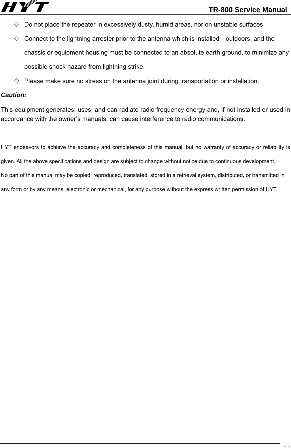
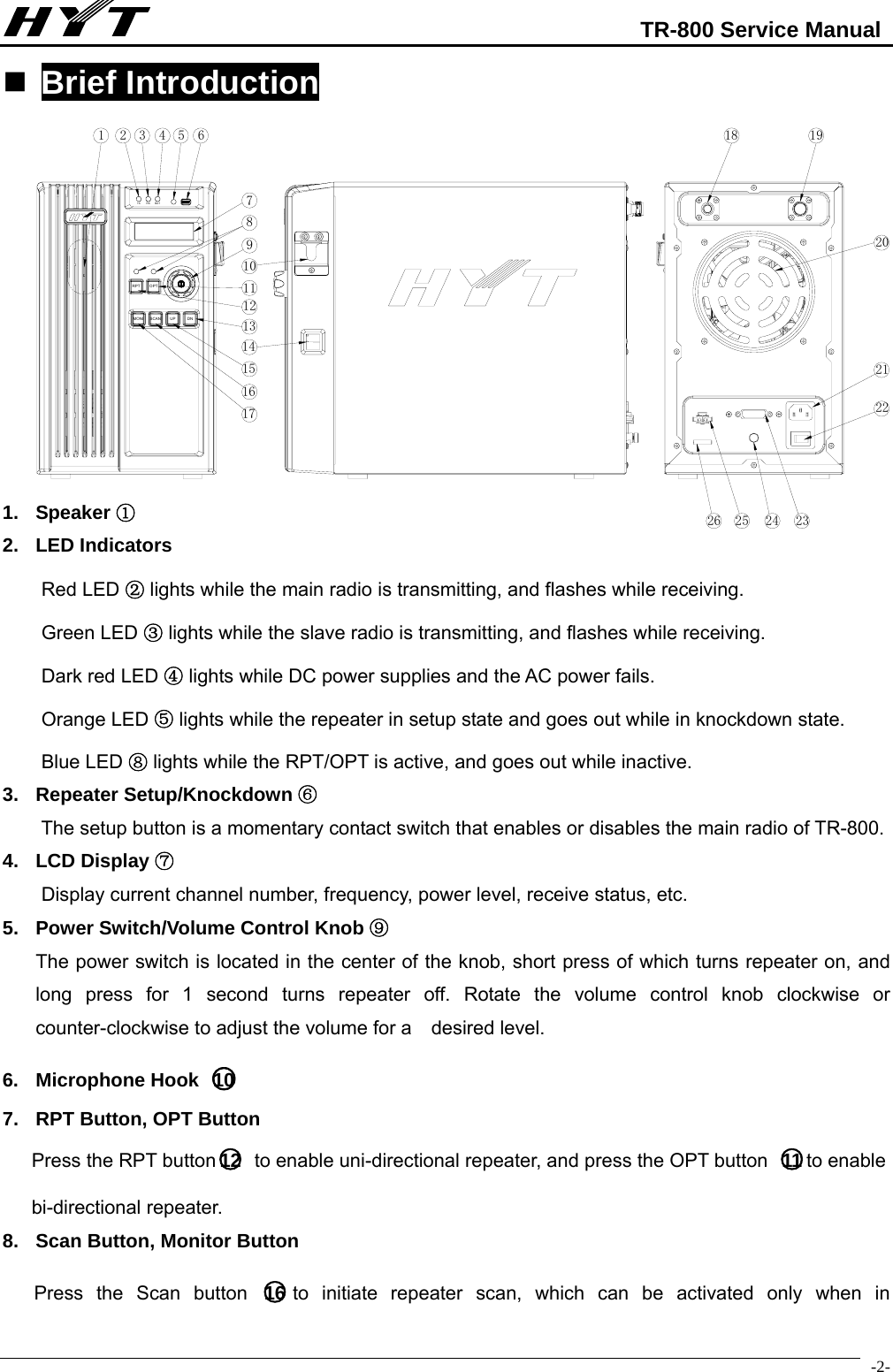
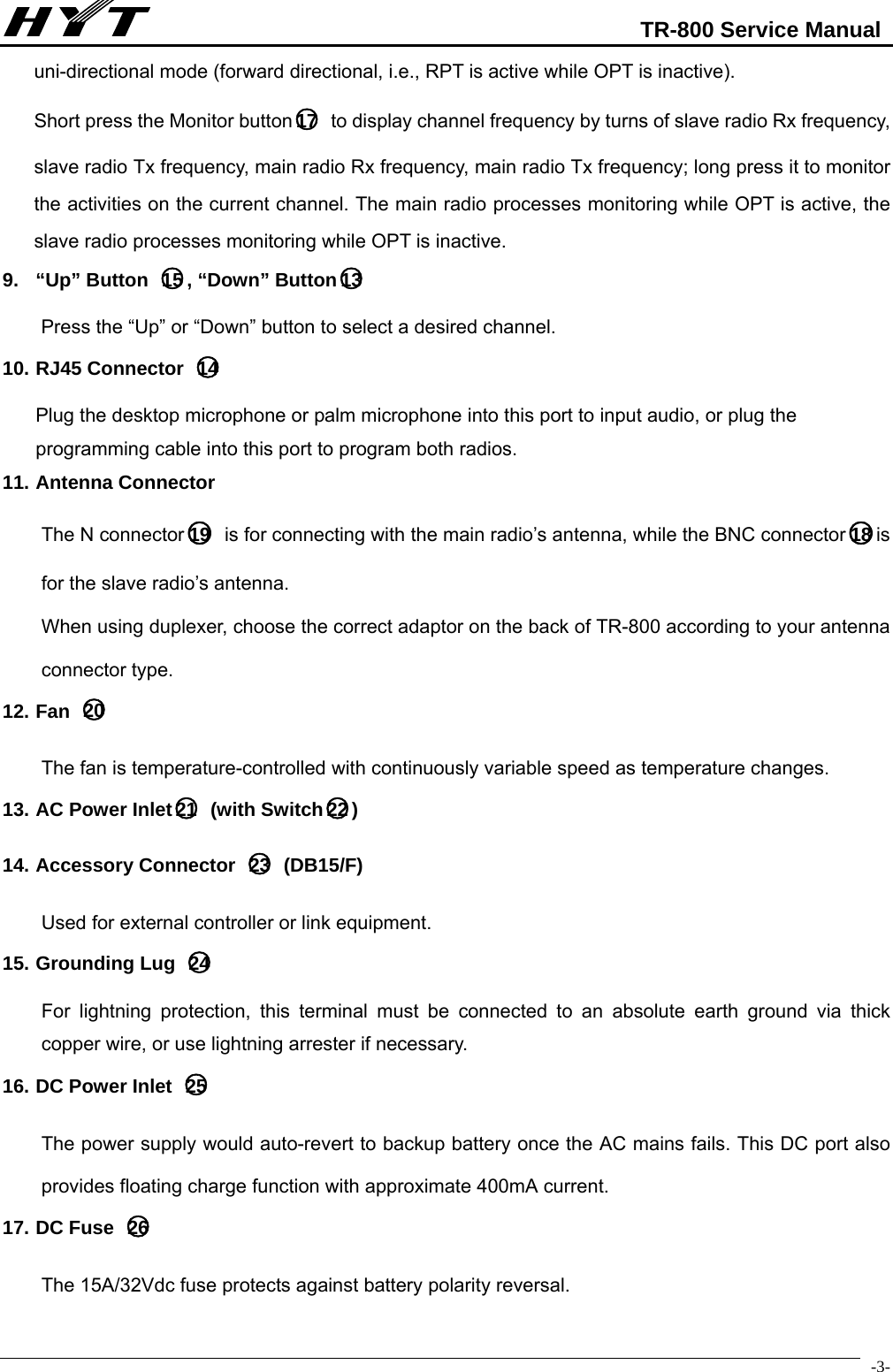
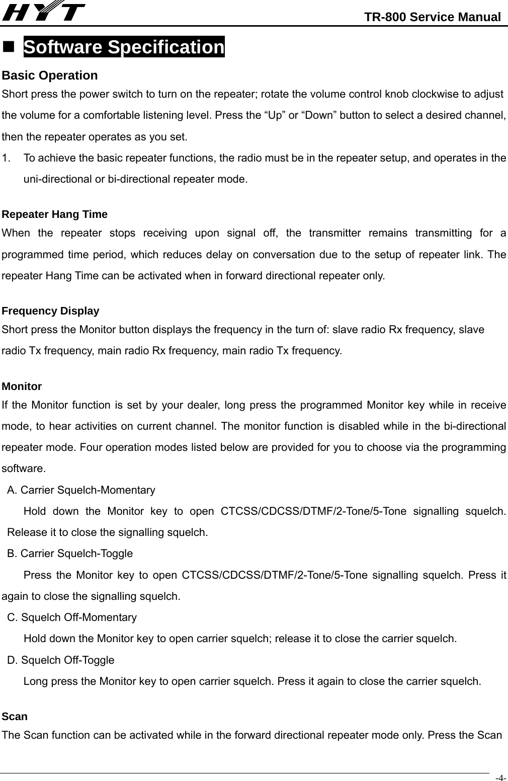
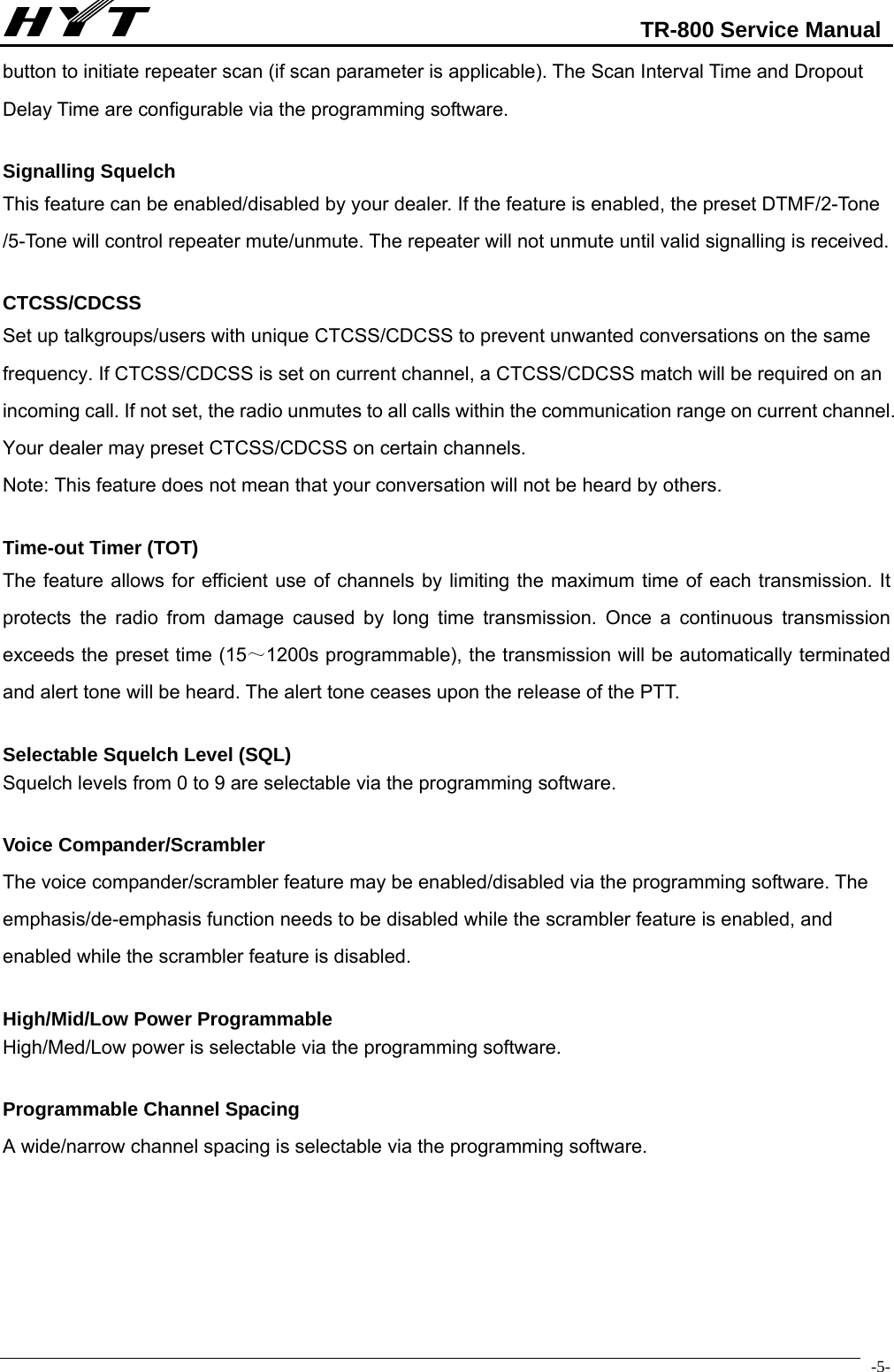

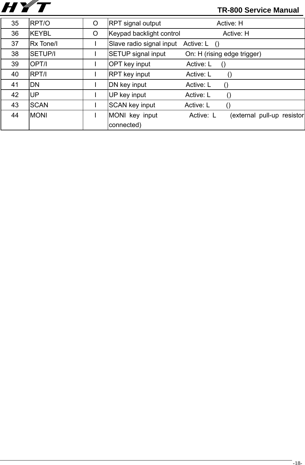
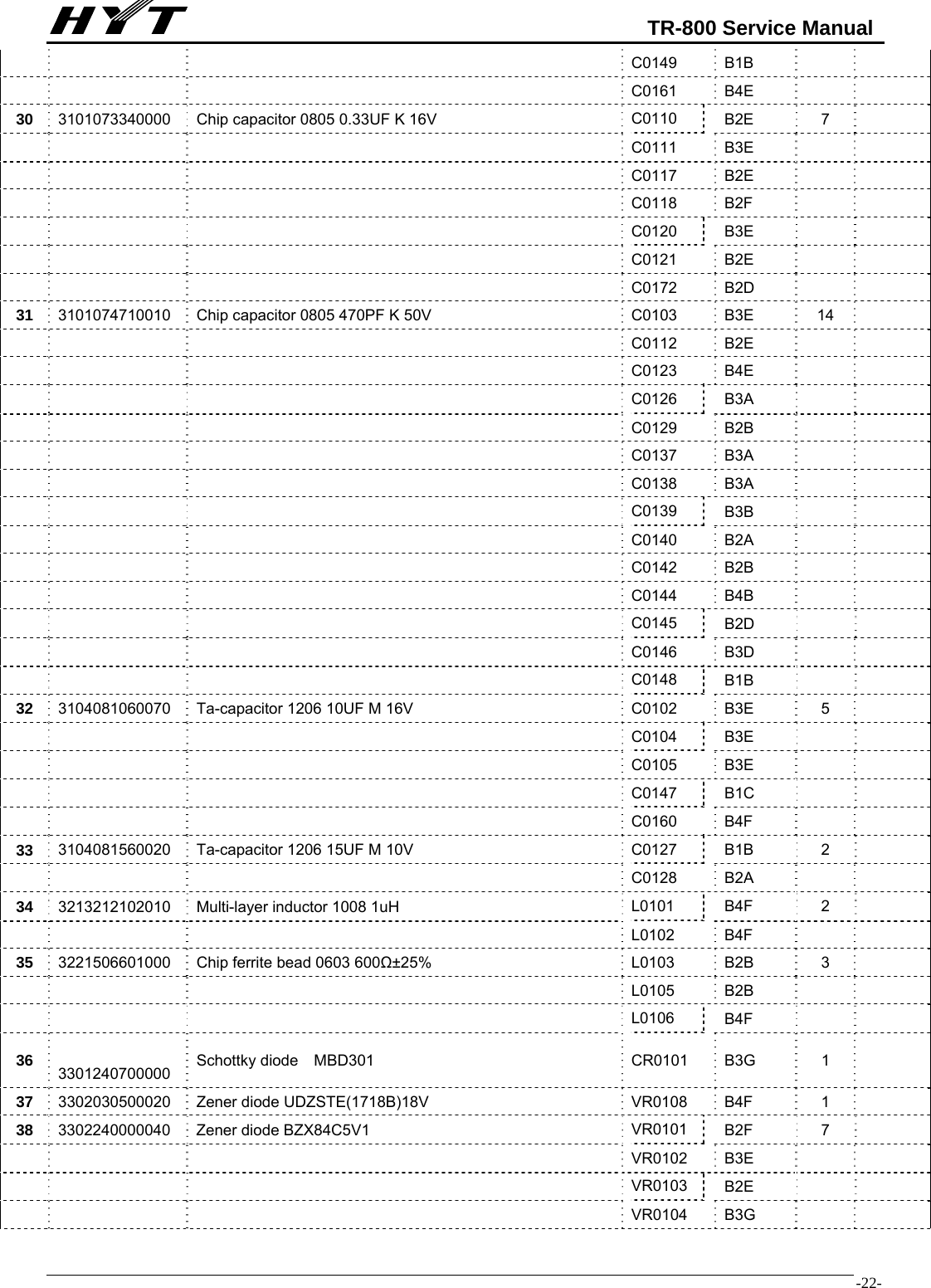
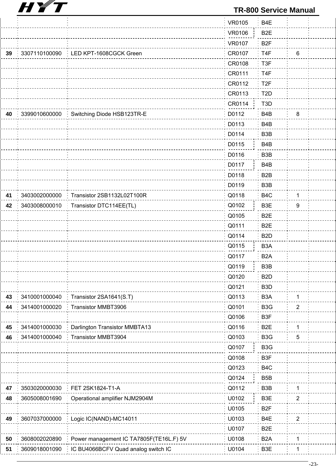
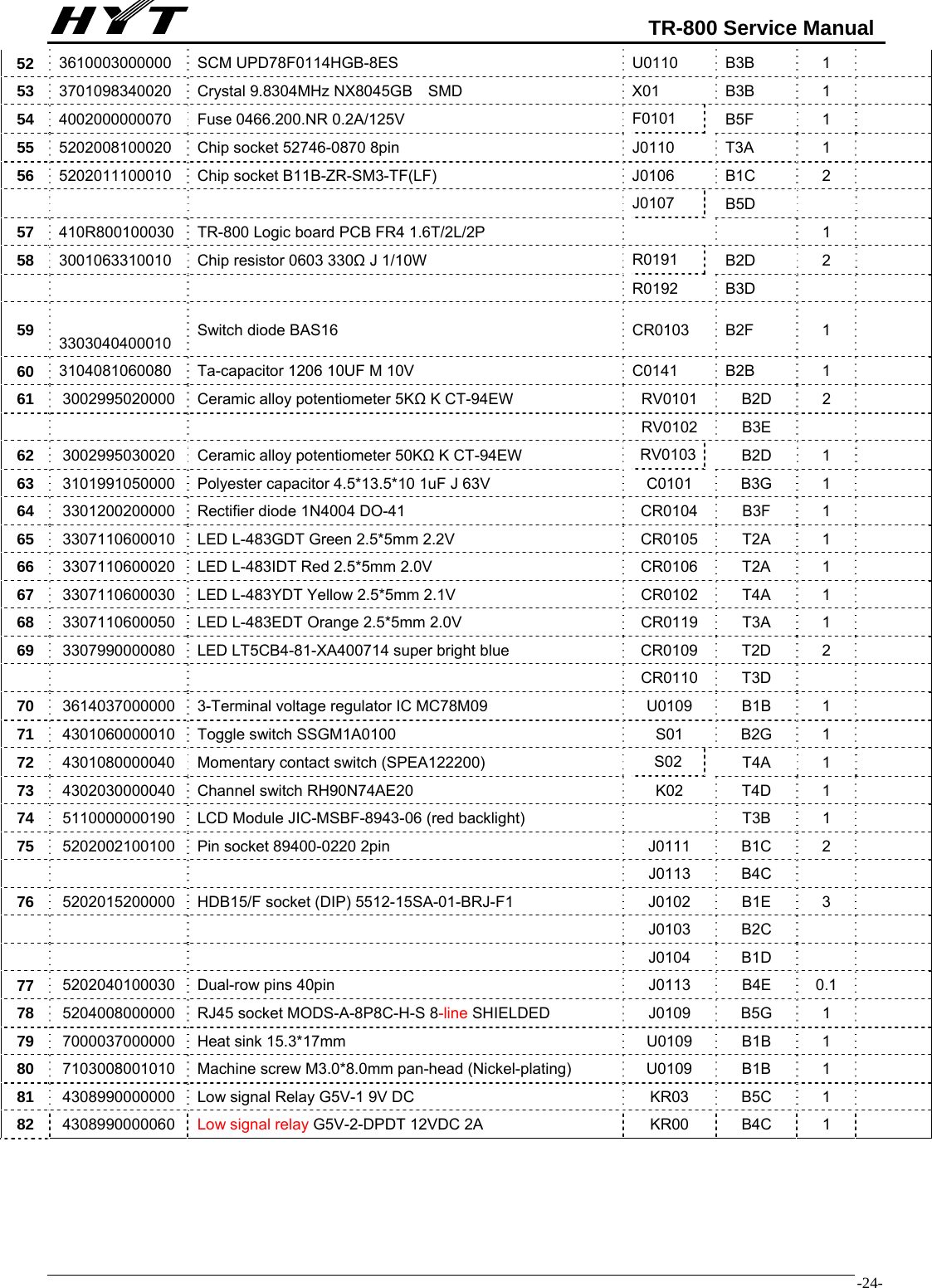
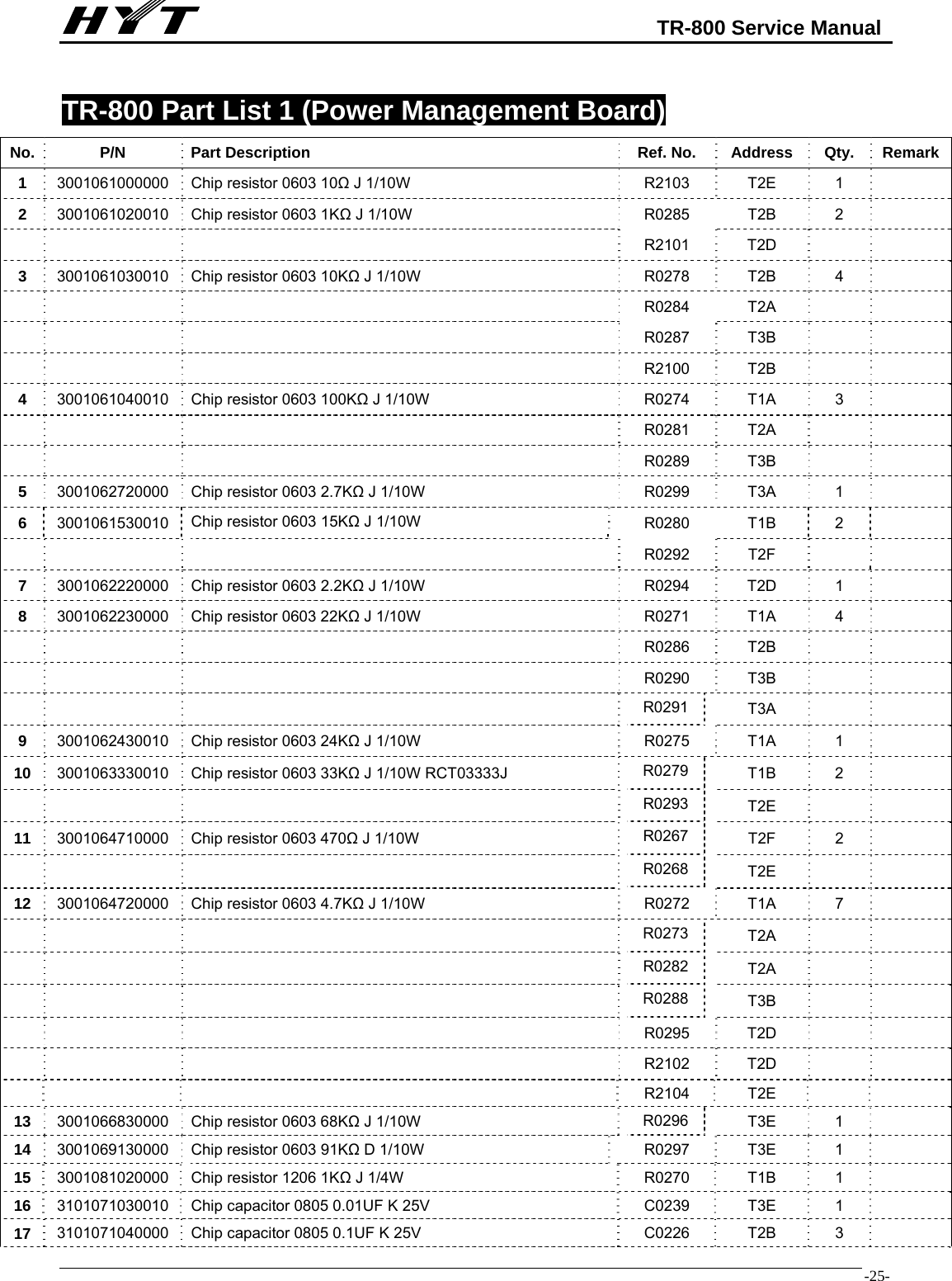
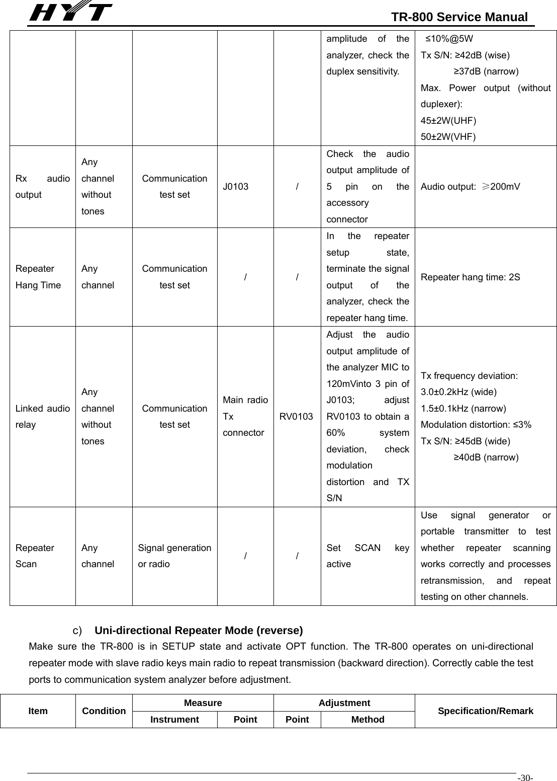
![TR-800 Service Manual -17- MPU Pins Repeater front panel (MPU Model: uPD780114, CRYSTAL: 9.8304MHz) PIN No. PIN NAME I/O DESCRIPTION 1 AVref I Connect VDD 2 AVss I To GND 3 IC(VPP) I To GND (programming pin) short-circuit resistor added 4 VDD I +5V 5 Vss I GND 6 X1 I Clock Input 7 X2 O Clock output 8 RESET I Knockdown 9 XT1 I NC Connect VDD 10 XT2 I NC Open 11 SHIFT O Clock Frequency Shift Active: H 12 PTT/O O Main radio PTT signal output control Active: L 13 RxD2 I Analog serial data input (slave MPU communication) 14 TxD2 O Analog serial data output (slave MPU communication) 15 RSW0(DN) I Encoder knob [DOWN] button input High/low level 16 RSW1(UP) I Encoder knob [UP] button input Rising Edge / Falling Edgeactive 17 LCDBL/LED0 O LCD backlight control/LED0 Active: H 18 LCDCS/LED1 O LCD chip selection output/LED1 19 LCDSOD/LED2 I/O LCD data reading/LED2 (LCD/LED I/O) 20 LCDDAT/LED3 O LCD data output/LED3 21 LCDCLK/LED4 O LCD clock output/LED4 22 EVss I GND 23 E VDD I Connect VDD (programming pin) 24 AFTest O Audio test control 25 SpkSW O Main/slave speaker output control H: Main unit outputs L: slave radio outputs 26 RXD1 I Serial data input (main MPU communication) 27 TXD1 O Serial data output (main MPU communication) 28 SETUP/O O Repeater setup output Active: H 29 HOOK/RXD0 I Palm microphone HOOK input/serial data input Active: L 30 TXD0 O Serial data output PTT active: L 31 RLED O Red LED Active: H 32 GLED O Green LED Active: H 33 PTT I Palm microphone PTT key input PTT Active: L 34 OPT/O O OPT signal output Active: H](https://usermanual.wiki/HYT-Science-and-Technology-Co/TR-800U2/User-Guide-904991-Page-21.png)