HYT Science and Technology Co TR-800V REPEATER (BASE STATION) User Manual User s Manual Add Information
Shenzhen HYT Science &Technology; Co Ltd REPEATER (BASE STATION) User s Manual Add Information
USERES MANUAL

SAFETYTRAINING INFORMATION
Your HYT radio generates RF electromagnetic energy during
transmit mode. This radio is designed for and classified as
“Occupational Use Only”, meaning it must be used only during
the course of employment by individuals aware of the hazards,
and the ways to minimize such hazards. This radio is NOT
intended for use by the “General Population” in an uncontrolled
environment.
This radio has been tested and complies with the FCC RF exposure limits for
“Occupational Use Only”. In addition, your HYT radio complies with the following
Standards and Guidelines with regard to RF energy and electromagnetic energy levels
and evaluation of such levels for exposure to humans:
FCC OET Bulletin 65 Edition 97-01 Supplement C, Evaluating Compliance with FCC
Guidelines for Human Exposure to Radio Frequency Electromagnetic Fields.
American National Standards Institute (C95.1-1992), IEEE Standard for Safety Levels
with Respect to Human Exposure to Radio Frequency Electromagnetic Fields, 3 kHz
to 300 GHz.
American National Standards Institute (C95.3-1992), IEEE Recommended Practice
for the Measurement of Potentially Hazardous Electromagnetic Fields– RF and
Microwave.
The following accessories are authorized for use with this product. Use of accessories
other than those (listed in the instruction) specified may result in RF exposure levels
exceeding the FCC requirements for wireless RF exposure.
To ensure that your expose to RF electromagnetic
energy is within the FCC allowable limits for
occupational use, always adhere to the following
guidelines:
DO NOT operate the radio without a proper antenna attached, as this may damaged
the radio and may also cause you to exceed FCC RF exposure limits. A proper
antenna is the antenna supplied with this radio by the manufacturer or antenna
specifically authorized by the manufacturer for use with this radio.
DO NOT transmits for more than 50% of total radio use time (“50%duty cycle”).
Transmitting more than 50% of the time can cause FCC RF exposure compliance
requirements to be exceeded. The radio is transmitting when the “TX indicator” lights
red. You can cause the radio to transmit by pressing the “PTT” switch.

ALWAYS keep the antenna at least 150 cm away from the body when transmitting
The information listed above provides the user with the information needed to make him
or her aware of RF exposure, and what to do to assure that this radio operates with the
FCC RF exposure limits of this radio.
Electromagnetic Interference/Compatibility
During transmissions, your HYT radio generates RF energy that can possibly cause
interference with other devices or systems. To avoid such interference, turn off the radio in
areas where signs are posted to do so. DO NOT operate the transmitter in areas that are
sensitive to electromagnetic radiation such as hospitals, aircraft, and blasting sites.
Occupational/Controlled Use
The radio transmitter is used in situations in which persons are exposed as consequence
of their employment provided those persons are fully aware of the potential for exposure
and can exercise control over their exposure.
IMPORTANT
READ ALL INSTRUCTIONS carefully and completely before using the
transceiver
SAVE THIS INSTRUCTION MANUAL- This instruction manual contains
important operating instructions for the Two-Way Radio
EXPLICIT DEFINITIONS
WORD DEFINITION
WARNING Personal injury, fire hazard or electric shock
may occur.
CAUTION Equipment damage may occur.
NOTE If disregarded, inconvenience only. No risk
of personal injury, fire or electric shock.

OPERATING NOTES
When transmitting, Please Keep the antenna at least 150 cm from your head and
body.
PRECAUTIONS
WARNING! NEVER hold the transceiver so that the antenna is very close to, or touching
exposed parts of the body, especially the face or eyes, while transmitting. The transceiver
will perform best if the microphone is 150 cm away from the antenna.
WARNING! NEVER operate the transceiver with a headset or other audio accessories at
high volume levels.
DO NOT push the PTT when not actually desiring to transmit.
AVOID using or placing the transceiver in direct sunlight or in areas with temperatures
below –30°C (–22°F) or above +60°C (+140°F).
DO NOT modify the transceiver for any reason.
FCC CAUTION:
Changes or modifications to this device, not expressly approved by HYT, could void
your authority to operate this transceiver under FCC regulations.

Revision History
P/N Release Date Revision
Initial Release
General
Manual Scope
This manual is intended for use by experienced technicians familiar with similar types of communication
equipment. It contains all service information required for the equipment and is current as of the
publication date.
Safety and General Information
The following general safety precautions as would normally apply, should be observed during all
phases of operation, service and repair of this equipment.
◇ This equipment should be serviced by qualified technicians only.
◇ Do not modify the repeater for any reason.
◇ To avoid electromagnetic interference and/or compatibility conflicts, do not operate your
repeater when you are near 380V AC mains or above.
◇ For vehicles with an air bag, do not place a repeater in the area over an air bag or in the air bag
deployment area. Air bags inflate with great force. If a repeater is placed in the air bag
deployment area and the air bag inflates, the repeater may be propelled with great force and
cause serious injury to occupants of the vehicle.
◇ Turn off your repeater prior to entering any area with a potentially explosive atmosphere.
◇ To avoid possible interference with blasting operations, turn off your repeater when you are near
electrical blasting caps, in a blasting area, or in areas posted: “Turn off two-way radio.” Obey all
signs and instructions.
◇ Do not charge your back-up battery in a potentially explosive atmosphere
◇ Do not expose the repeater to direct sunlight over a long time, nor place it close to heating
source.

TR-800 Service Manual
-1-
◇ Do not place the repeater in excessively dusty, humid areas, nor on unstable surfaces
◇ Connect to the lightning arrester prior to the antenna which is installed outdoors, and the
chassis or equipment housing must be connected to an absolute earth ground, to minimize any
possible shock hazard from lightning strike.
◇ Please make sure no stress on the antenna joint during transportation or installation.
Caution:
This equipment generates, uses, and can radiate radio frequency energy and, if not installed or used in
accordance with the owner’s manuals, can cause interference to radio communications.
HYT endeavors to achieve the accuracy and completeness of this manual, but no warranty of accuracy or reliability is
given. All the above specifications and design are subject to change without notice due to continuous development.
No part of this manual may be copied, reproduced, translated, stored in a retrieval system, distributed, or transmitted in
any form or by any means, electronic or mechanical, for any purpose without the express written permission of HYT.
TR-800 Service Manual
-2-
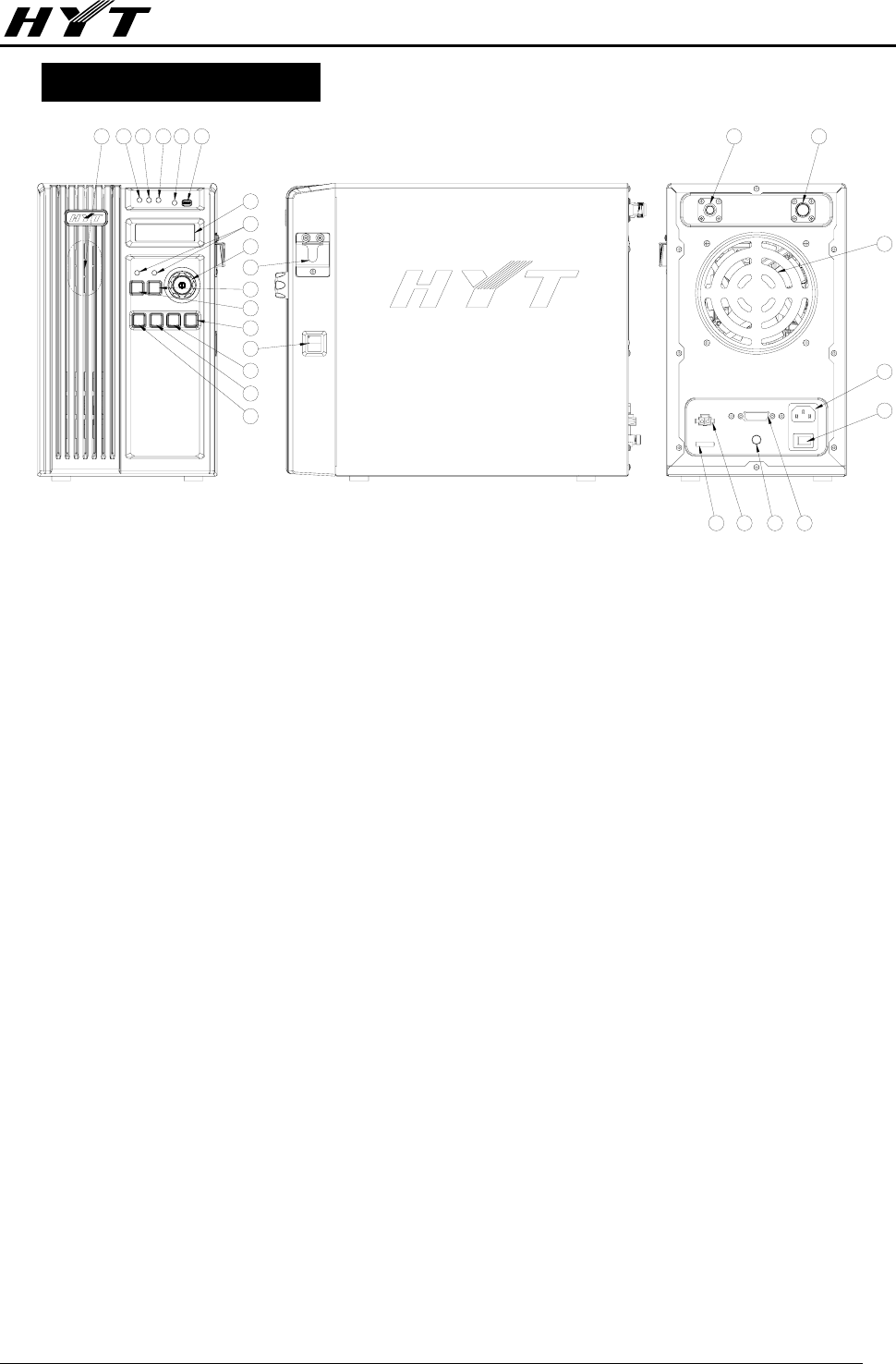
Brief Introduction
1. Speaker ①
2. LED Indicators
Red LED ②lights while the main radio is transmitting, and flashes while receiving.
Green LED ③ lights while the slave radio is transmitting, and flashes while receiving.
Dark red LED ④ lights while DC power supplies and the AC power fails.
Orange LED ⑤ lights while the repeater in setup state and goes out while in knockdown state.
Blue LED ⑧ lights while the RPT/OPT is active, and goes out while inactive.
3. Repeater Setup/Knockdown ⑥
The setup button is a momentary contact switch that enables or disables the main radio of TR-800.
4. LCD Display ⑦
Display current channel number, frequency, power level, receive status, etc.
5. Power Switch/Volume Control Knob ⑨
The power switch is located in the center of the knob, short press of which turns repeater on, and
long press for 1 second turns repeater off. Rotate the volume control knob clockwise or
counter-clockwise to adjust the volume for a desired level.
6. Microphone Hook
○
10
7. RPT Button, OPT Button
Press the RPT button○
12 to enable uni-directional repeater, and press the OPT button ○
11 to enable
bi-directional repeater.
8. Scan Button, Monitor Button
Press the Scan button ○
16 to initiate repeater scan, which can be activated only when in
1
17
16
15
12
11
19
TX RX BAT
RPT OPT
MONI SCAN UP DN
23456
7
8
9
13
10
14
18
20
21
22
23242526

TR-800 Service Manual
-3-
uni-directional mode (forward directional, i.e., RPT is active while OPT is inactive).
Short press the Monitor button○
17 to display channel frequency by turns of slave radio Rx frequency,
slave radio Tx frequency, main radio Rx frequency, main radio Tx frequency; long press it to monitor
the activities on the current channel. The main radio processes monitoring while OPT is active, the
slave radio processes monitoring while OPT is inactive.
9. “Up” Button
○
15 , “Down” Button○
13
Press the “Up” or “Down” button to select a desired channel.
10. RJ45 Connector ○
14
Plug the desktop microphone or palm microphone into this port to input audio, or plug the
programming cable into this port to program both radios.
11. Antenna Connector
The N connector○
19 is for connecting with the main radio’s antenna, while the BNC connector○
18 is
for the slave radio’s antenna.
When using duplexer, choose the correct adaptor on the back of TR-800 according to your antenna
connector type.
12. Fan ○
20
The fan is temperature-controlled with continuously variable speed as temperature changes.
13. AC Power Inlet○
21 (with Switch○
22 )
14. Accessory Connector ○
23 (DB15/F)
Used for external controller or link equipment.
15. Grounding Lug ○
24
For lightning protection, this terminal must be connected to an absolute earth ground via thick
copper wire, or use lightning arrester if necessary.
16. DC Power Inlet ○
25
The power supply would auto-revert to backup battery once the AC mains fails. This DC port also
provides floating charge function with approximate 400mA current.
17. DC Fuse ○
26
The 15A/32Vdc fuse protects against battery polarity reversal.

TR-800 Service Manual
-4-
Software Specification
Basic Operation
Short press the power switch to turn on the repeater; rotate the volume control knob clockwise to adjust
the volume for a comfortable listening level. Press the “Up” or “Down” button to select a desired channel,
then the repeater operates as you set.
1. To achieve the basic repeater functions, the radio must be in the repeater setup, and operates in the
uni-directional or bi-directional repeater mode.
Repeater Hang Time
When the repeater stops receiving upon signal off, the transmitter remains transmitting for a
programmed time period, which reduces delay on conversation due to the setup of repeater link. The
repeater Hang Time can be activated when in forward directional repeater only.
Frequency Display
Short press the Monitor button displays the frequency in the turn of: slave radio Rx frequency, slave
radio Tx frequency, main radio Rx frequency, main radio Tx frequency.
Monitor
If the Monitor function is set by your dealer, long press the programmed Monitor key while in receive
mode, to hear activities on current channel. The monitor function is disabled while in the bi-directional
repeater mode. Four operation modes listed below are provided for you to choose via the programming
software.
A. Carrier Squelch-Momentary
Hold down the Monitor key to open CTCSS/CDCSS/DTMF/2-Tone/5-Tone signalling squelch.
Release it to close the signalling squelch.
B. Carrier Squelch-Toggle
Press the Monitor key to open CTCSS/CDCSS/DTMF/2-Tone/5-Tone signalling squelch. Press it
again to close the signalling squelch.
C. Squelch Off-Momentary
Hold down the Monitor key to open carrier squelch; release it to close the carrier squelch.
D. Squelch Off-Toggle
Long press the Monitor key to open carrier squelch. Press it again to close the carrier squelch.
Scan
The Scan function can be activated while in the forward directional repeater mode only. Press the Scan

TR-800 Service Manual
-5-
button to initiate repeater scan (if scan parameter is applicable). The Scan Interval Time and Dropout
Delay Time are configurable via the programming software.
Signalling Squelch
This feature can be enabled/disabled by your dealer. If the feature is enabled, the preset DTMF/2-Tone
/5-Tone will control repeater mute/unmute. The repeater will not unmute until valid signalling is received.
CTCSS/CDCSS
Set up talkgroups/users with unique CTCSS/CDCSS to prevent unwanted conversations on the same
frequency. If CTCSS/CDCSS is set on current channel, a CTCSS/CDCSS match will be required on an
incoming call. If not set, the radio unmutes to all calls within the communication range on current channel.
Your dealer may preset CTCSS/CDCSS on certain channels.
Note: This feature does not mean that your conversation will not be heard by others.
Time-out Timer (TOT)
The feature allows for efficient use of channels by limiting the maximum time of each transmission. It
protects the radio from damage caused by long time transmission. Once a continuous transmission
exceeds the preset time (15~1200s programmable), the transmission will be automatically terminated
and alert tone will be heard. The alert tone ceases upon the release of the PTT.
Selectable Squelch Level (SQL)
Squelch levels from 0 to 9 are selectable via the programming software.
Voice Compander/Scrambler
The voice compander/scrambler feature may be enabled/disabled via the programming software. The
emphasis/de-emphasis function needs to be disabled while the scrambler feature is enabled, and
enabled while the scrambler feature is disabled.
High/Mid/Low Power Programmable
High/Med/Low power is selectable via the programming software.
Programmable Channel Spacing
A wide/narrow channel spacing is selectable via the programming software.

TR-800 Service Manual
-6-
Repeater Modes

TR-800 Service Manual
-7-
Knockdown Mode
Setup Mode
Base Station
Forward Directional
Repeater
Reverse Directional
Repeater
Bi-directional Repeater
PC Programming Mode
Modes Description
Mode Description
Knockdown
Press the SETUP button while the repeater is
power on. The repeater enters knockdown
mode once the orange LED goes out.
Base Station
Press RPT and OPT buttons when the SETUP
orange LED is on. The radio enters base
station mode once both the RPT and OPT
blue LEDs go out.
Forward Directional
Repeater
Press RPT and OPT buttons when SETUP
orange LED is on. The repeater enters
forward directional mode once the RPT blue
LED is on while the OPT blue LED goes out.
Reverse Directional
Repeater
Press RPT and OPT buttons when the SETUP
orange LED is on. The repeater enters
reverse directional mode once the RPT blue
LED goes out while the OPT blue LED is on.
Setup
Bi-directional Repeater
Press RPT and OPT buttons when the SETUP
orange LED is on. The repeater enters
bi-directional repeater mode once both the
RPT and OPT blue LEDs is on.
PC Programming
The repeater enters PC programming mode
once command is received from PC, while the
SETUP orange LED is on.
Repeater Setup/Knockdown
TR-800 Service Manual
-8-
Press the SETUP button located on the front panel to toggle between repeater setup and knockdown,
with LED indications. While in setup state, both radios turn on at power up; in knockdown state, only
receive radio turns on at power up. There are three repeater types: base station, uni-directional and
bi-directional in the repeater setup state. The repeater is initialized to base station mode when it toggles
from knockdown to setup state. But in the knockdown state, the repeater works only as a receiver.
In base station mode, the repeater function is disabled, with the slave radio as a receiver and the main
radio as a transmitter. In bi-directional repeater mode, the front panel PTT is disabled.
The repeater setup/knockdown status will be recorded after the repeater power failure. (E.g. If the
repeater operates in forward directional mode, it will still work in such mode after the power recovers)
PC Programming Mode
Connect the PC with the repeater via programming cable. Data can be transmitted from PC to the
repeater. Repeater LCD displays “PROGRAMMING” while reading/writing data from/into the radio, with
red LED flashes indicating programming the main radio, and then green LED flashes indicating
programming the slave radio. The repeater resets automatically after programming is finished.
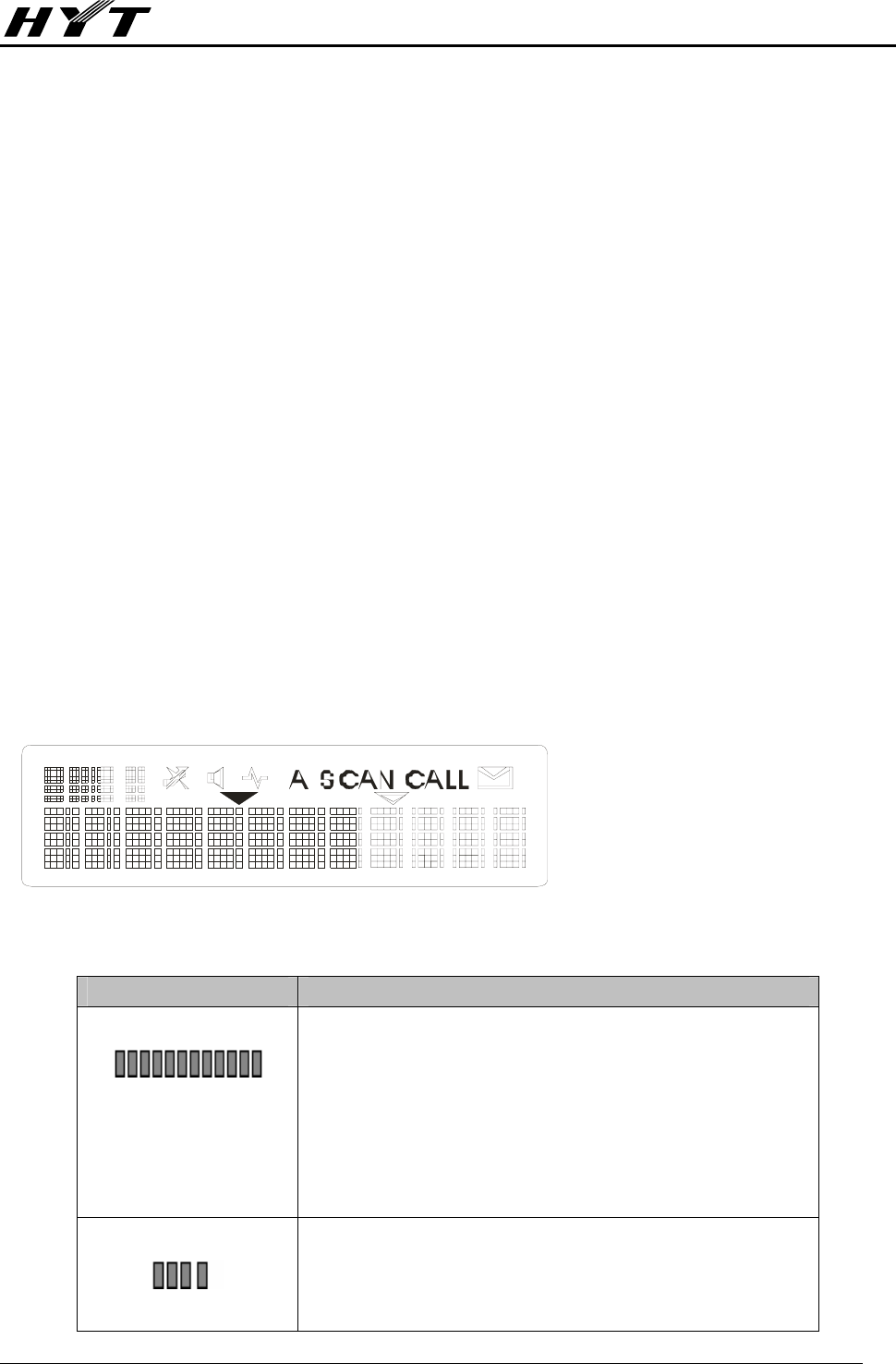
LCD Display
LCD Icon Description
Indicator Description
1. Displays zone/channel number
2. Displays zone/channel name up to 12 alphanumeric
characters (preprogrammed by your dealer)
3. Displays channel frequency
4. Displays preprogrammed function
1. Displays zone/channel number
2. Displays transmit power level (the 4th digit: H, M, L)
3. Displays preprogrammed function
TR-800 Service Manual
-9-
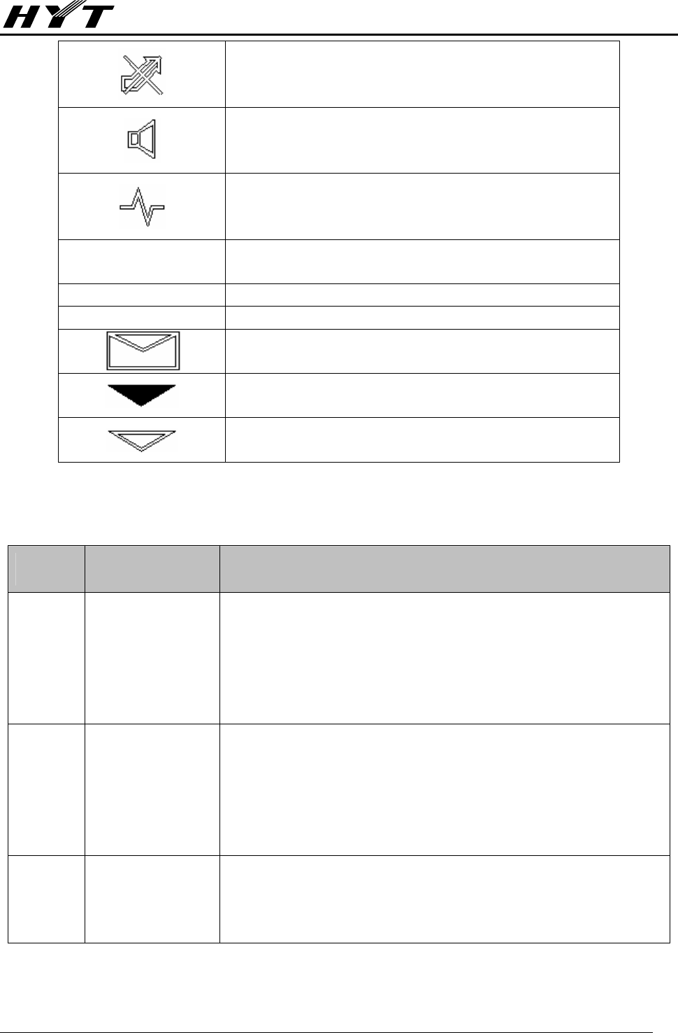
Appears when the current channel is already in use
Appears when the Monitor key is pressed to disable
CTCSS/DCS, DTMF, 2-Tone/5-Tone decoding.
Appears when the repeater is unmuted upon the monitor
key is pressed.
A Indicates the feature development feature.
SCAN Appears while repeater scanning.
CALL Appears when transmitting a selective call.
Appears when a message is received.
Reserved
Reserved
LED Indicator
LEDs indicate real-time radio status shown as the following table:
LED Description Indicates:
Tx Red
1. Lights while the main radio is transmitting.
2. Flashes while the main radio is receiving.
3. Flashes while the main radio is monitoring channel activities.
4. Flashes while programming the main radio.
Rx Green
1. Lights while the slave radio is transmitting.
2. Flashes while the slave radio is receiving.
3. Flashes while the slave radio is monitoring channel activities.
4. Flashes while programming the slave radio.
RPT Blue, ultra bright
1. Lights while the RPT is active.
2. Goes out while the RPT is inactive.

TR-800 Service Manual
-10-
OPT Blue, ultra bright
1. Lights while the OPT is active.
2. Goes out while the OPT is inactive.
SETUP Orange
1. Lights while in the Setup state.
2. Goes out while in the Knockdown state.
BAT Dark red
1. Lights while the backup battery supplies power.
2. Goes out while the AC mains supplies power.

TR-800 Service Manual
-11-
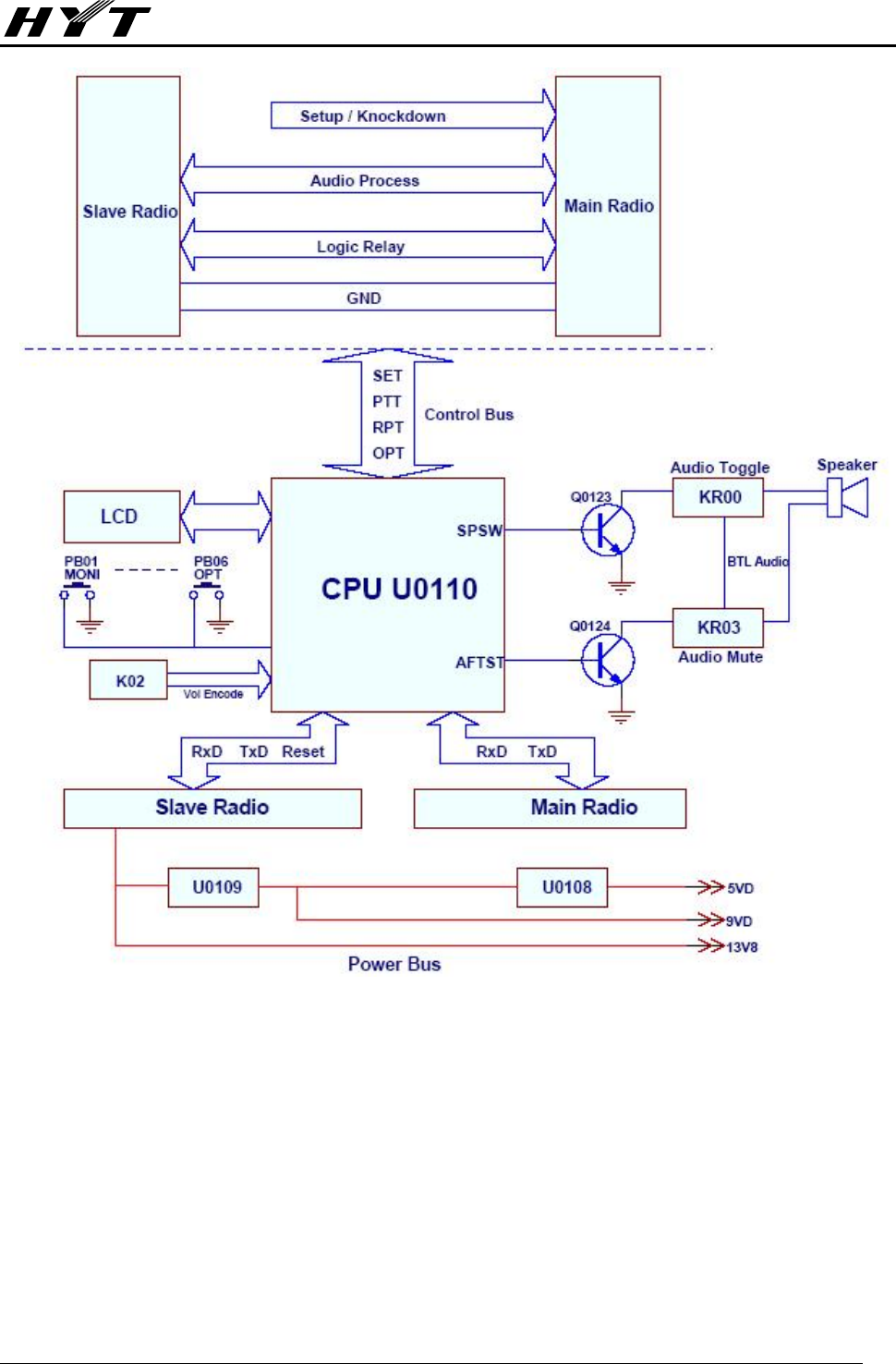
Circuit Description
Repeater Communication Interface & Display Unit
Theory of Operation
Setup/Knockdown (U0107D, Q0101, Q0103, Q0106, Q0107 and Q0108):
The Setup/Knockdown state at power-up can be configured via HR-800 programming software. The
electronic switch, Q0106 and Q0108, causes the Setup/Knockdown action by applying or removing
voltage at the ignition control, pin15, of “J0102-Main”. After power-up, the Setup or Knockdown state
may be changed remotely with a signal from pin10 of “J4-Slave” or locally through the front panel
SETUP. S0102 is a momentary contact switch that is debounced by the Q0103/Q0107 latch circuit. The
orange “SETUP” LED, CR0102, illuminates to indicate the Setup state.
As the Setup/Knockdown circuit goes from the Knockdown to the Set-up state, Q1 is momentarily turned
on by Q0108 via the C0101/R0103 timing circuit. The push to talk (PTT) input of the slave radio, pin8 of
“J4-Slave” is pulled low by Q0101 and keys the transmitter. The “Rx” LED, CR0105, will briefly flash
during the moment that Q0101 is conducting.
Forward Audio Routing (U0103A, U0104A, U0104D and U0105A):
The audio gate, U0104D, quarter of an analog switch BU4066B, enables and disables the audio from
front panel MIC audio input. U0104D is turned on with an active dc level high driven at the output of
NAND gate U0103A-3 by the front panel PTT input. The salve radio audio output from pin5 of
“J0104-Slave” is routed to a potentiometer, RV0101. The output of RV0101 is applied to another switch
U0104A. U0104A is enabled once a valid signal is received and will route the audio to transmitter. The
external audio input, ACC Relay audio, is routed to another potentiometer, RV0103. The output of
RV0103 is applied to the second half of U0105, an operational amplifier NJM2904. U0105A, R1106 and
R0118 make a buffer amplifier for the link audio. All the “forward” audio will mix together and route
through S0101-5 to the main microphone transmitter audio, pin2 of “J0106-Main”.
Reverse Audio Routing (U0104B and U0104C):
Part of front panel MIC audio is routed to the input of U0104B, quarter of the analog switch BU4066B.
The output of U0104B is also controlled with an active low input by the front panel PTT. Audio present on
pin5 of “J0102-Main” is routed through S0102-7 to a potentiometer, RV0102, which is used to adjust the
audio level for proper deviation. As with the forward direction, the audio output of RV0102 is applied to
an analog switch U0106A. This switch turns on only if a valid signal is detected and pin6 of U0104 goes
high.
Forward and Reverse Key-up (Q0102, U0103, U0107, Q0105, Q0111 and Q0116):
When a valid input signal is present at the slave radio, pin6 of “J0104-Slave” will be pulled low and turn
off Q0105 through two NAND gates, U0107B and U0107C, along with RPT enable trigger. A dc level
high output from Q0105 will be applied to pin37 of U0110 and keys the main radio PTT through output
from pin12. The red “Tx” LED, CR0106, illuminates.
When the reverse key-up function is enabled, as in the bi-directional repeater configuration, S0101-8
must be on. Q0116 is a dc amplifier (buffer) for the Rx Carrier signal from pin6 of “J0102-Main”. An active

TR-800 Service Manual
-12-
low state at the input of the NAND gate U0107A, one quarter of a MC14011B, will be conversed to a high
state to drive the buffer for the Rx Carrier signal. The active low level of Rx Carrier signal, along with the
OPT enable signal, cause a series of NAND gates, U0103D, U0103C and U0103B to generate a high dc
level to turn on Q0102. The output of Q0102 is pulled low for pin8 of “J0104-Slave” and keys the
transmitter of slave radio. The green “Rx” LED, CR0105, illuminates.
Q0111 is used to prevent the simultaneous active state on PTT and Rx Carrier signal of “J0102-Main”,
which possibly causes unwanted tie condition of keying of both radios.
Accessory D-SUB 15pin receptacle (“J0103-Acc”)
The accessory D-Sub, “J0103-ACC”, is connected to “J0102-Main” and “J0104-Slave” to supply Rx
audio and PTT for linked radios (repeaters) or external controllers. Receive audio and PTT activation
from the linked facilities are applied to the repeater for transmission.
Display Unit (U0110, PB01-PB06, K02, Q0113 and Q0118)
All the functional triggers of enable and disable come from keypad PB01 to PB06. K02 is an encoder
switch for front speaker audio output adjustment. A high output from pin37 of CPU U0110 will turn Q0119
on, driving the base of Q0118 to go low. The backlight LED for the keypad, CR0107, CR0108,
CR0111-CR0114 illuminate. Another backlight driver, Q0113, is controlled by Q0114 through the output
from pin17 of U0110.
Peripheral Circuitry (U0108, U0109, KR00 and KR03)
Operating power bus for all the electronics originates from the switch power 13.8Vdc output, pin9 of
“J0107-Slave”, and goes through U0109 and U0108 to obtain the reference voltages of 9Vdc and 5Vdc.
KR00 is a DPDT relay driven by transistor Q0123. The output from pin25 of U0110 will turn on/off Q0123,
which activates relay KR00 to toggle the front speaker audio routes from slave radio or from main radio.
KR03 is another SPDT relay for audio test requirement. A dc level high output from pin26 of U0110 will
turn on Q0124 and keys relay KR03. The receive audio to the speaker is blocked and routes only to pin8
of the front RJ45 connector J0109.
IMPORTANT NOTE
Using CTCSS or CDCSS tones may have a lower
probability to open squelch than carrier operation. But the
CTCSS codes near 100Hz and 150Hz have a high false
opening probability due to 50Hz AC power harmonics.
Countries having 60Hz AC power may have false opening
on 120Hz and 180Hz. CTCSS code 254.1Hz has a high
probability of squelch tails.
TR-800 Service Manual
-13-
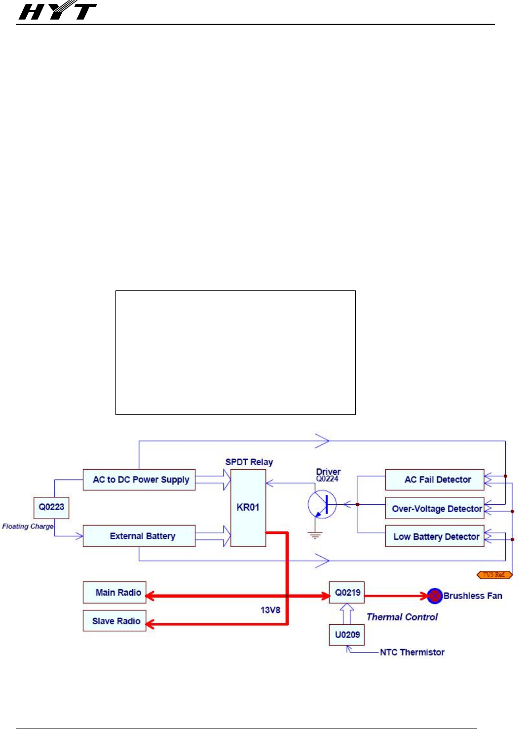
Figure Block DiagramⅠ

TR-800 Service Manual
-14-
Power Management
Theory of Operation
Battery Revert Circuit:
A voltage reference network consisting of CR0212, CR0213, R0268, and VR0209 provides a stable
voltage reference of 7.5Vdc. This reference voltage, at the anode of VR0209, is applied to the negative
input of the Over Voltage Detector U0206B-6, to the positive input of AC Fail Detector U0206A-3, and to
the positive input of the Low Battery Detector U0205B-5. Operating positive supply voltage for the
integrated circuits is obtained from the TR-800 power supply through CR0212 when the TR-800 is
operating on AC mains input power. The supply voltage is obtained through CR02013 when the station is
operating on the battery.
During normal operation under AC mains power, the negative input of the AC Fail Detector U0206A-2 is
more positive than the positive input U0206A-3. The output of U0206A-1 is low and Q0224, the driver for
relay KR01, and Q0216, the “BATTERY ON” driver, are turned off. When AC mains power is lost, the
voltage at U0206A-2 becomes lower than the reference voltage applied to U0206A-3. The output at
U0206A-1 then goes high and turns on both Q0224, which activates relay KR01 and transistor Q0216,
which provides a low at the output point “BATTERY ON”. The “BAT ON” LED, CR0219, illuminates to
indicate the DC power supply is operating.
If the battery voltage falls below approximately 10.2Vdc, the output at U0205B-7 will go high. This action
turns on Q0218 that shunts the base drive to Q0224 through CR0217 and turns off the relay. Q0218 also
provides a low through CR0218 at output point “BAT LOW”. This auxiliary output might be used to key a
portable radio to signal the repeater operator that the battery has exceeded the low voltage limit for the
radios. Hysteresis is provided by the feedback network consisting of CR0221, R0289 and R0288 from
the output of U0205B-7 to the positive input U0205B-5. The reference voltage at the positive input of
U0205B-5 is increased such that the battery voltage must rise above 12Vdc before relay KR01 will
reactivate and place the TR-800 back on battery power. This latching action is used to prevent
excessively deep discharging of the battery.
The repeater will remain turned off until either AC mains return or a charged battery is substituted for the
discharged battery. The circuit consisting of C0233, R0285, R0286, CR0220, R0287 and Q0217 resets
U0205B-7 to low upon the return of the AC mains power.
Capacitor C0234 at the negative input of U0205B-6 smoothes the variation in the battery voltage
between the transmit radio keyed and unkeyed conditions. Capacitor C0230 at U0206A-2 input, in
conjunction with C0234 at U0205B-6, ensures proper resetting of U0205B with the return of the AC
mains power.
The Over Voltage Detector consisting of U0206B and resistors R0274, R0275 and R0271 monitors the
DC output of the TR-800 power supply. If the voltage exceeds 16.4Vdc, the output of U0206B-7 goes
high and turns on relay driver Q0224. The station switches to battery power although there is no
indication at the “BAT ON” output point.
Zener diodes VR0210, VR0211, VR0212, VR0215 and VR0216 protect the electronics from damage by
accidental static discharge.
Fuse F0203-15A and diode and CR0215 provide protection from reverse polarity if the battery is
inadvertently connected “backward”.
TR-800 Service Manual
-15-
Variable speed, Temperature controlled Fan Circuit:
The TL431AILP is a three-terminal programmable shunt regulator diode. This monolithic IC voltage
reference operates as a low temperature coefficient zener that is programmed from 6Vdc to 12Vdc with
a resistor network consisting of R0296, R0297 and an NTC thermistor Rth0201. Q0219 operates as a
fast power switch between “ON” and “OFF” (similar to PWM mode) controlled by the output at cathode of
TL431AILP. The rotating speed of brushless fan is voltage controlled at collector of Q0219. The higher
temperature, the higher power supply to the fan, hence the faster it rotates.
Battery charging (Float Maintenance) Circuit:
The battery charging circuit is intended for use with sealed lead acid gel cell batteries. The charging
current, limited to approximately 400mA, is used to maintain a “float” charging condition on the battery.
After operating the TR-800 station on the battery for long periods of time, or if the battery reaches the low
battery limit of the revert circuit, the battery must be recharged with an external high-current charger.
Recharging with the internal trickle charger requires an extended period of time.
The trickle charging voltage is derived from AC mains. Resistors R0269 limit the charging current to
approximately 400mA to a partially discharged battery (terminal voltage of 12Vdc). Once the battery is
fully charged, the current will decrease to 10 to 25mA to float the battery at a terminal voltage of 13.6Vdc.
NOTE
This trickle charger is intended to maintain the
battery for long periods of time between power
failures and is not intended for charging a fully
discharged battery. If the battery is completely
discharged, it must be removed and charged via a
battery charger with higher current capability.
Figure Block DiagramⅡ

TR-800 Service Manual
-16-
Glossary
Bi-directional Repeater:
A repeater configuration in which the main and slave radios perform both receive and transmit functions.
The audio and Rx Carrier signals from the receiver of the slave radio are routed to the transmitter of the
main radio. Unlike the unidirectional case, though, the audio and Rx Carrier signals of the receiver of the
main radio are also routed to the transmitter of the slave radio.
Cross band repeater:
A repeater in which the slave radio operates in a different frequency band than the main radio. Example:
the slave radio operates on 162.075MHz in the high band VHF and the main radio operates on
452.025MHz in the 450-470MHz UHF band. Cross-band repeaters may be either unidirectional or
bi-directional.
Main Radio:
The radio that performs the transmitting functions in the TR800 repeater station in the general
unidirectional application.
Relay Delay Time:
The time duration the repeater remains in transmit mode after an active or valid signal is no longer
detected.
Repeater Knockdown:
To deactivate a repeater or to remove it from service. Only the slave radio turns on at power up.
Repeater Setup:
To activate a repeater or to place it into service. Both radios turn on at power-up (repeater functional).
Single band repeater:
A repeater in which both the slave radio operates in a same frequency band. Example: receive at
455.075MHz and transmit at 460.075MHz in the 450-470MHz UHF band.
Slave Radio:
The radio that performs the receiving functions in the TR800 repeater station in the general
unidirectional application.
Unidirectional Repeater:
A repeater configuration in which the slave radio receives signals only from the field radios and the main
radio transmits signals only to the field radios.

TR-800 Service Manual
-17-
MPU Pins
Repeater front panel
(MPU Model: uPD780114, CRYSTAL: 9.8304MHz)
PIN No. PIN NAME I/O DESCRIPTION
1 AVref I Connect VDD
2 AVss I To GND
3 IC(VPP) I To GND (programming pin) short-circuit resistor added
4 VDD I +5V
5 Vss I GND
6 X1 I Clock Input
7 X2 O Clock output
8 RESET I Knockdown
9 XT1 I NC Connect VDD
10 XT2 I NC Open
11 SHIFT O Clock Frequency Shift Active: H
12 PTT/O O Main radio PTT signal output control Active: L
13 RxD2 I Analog serial data input (slave MPU communication)
14 TxD2 O Analog serial data output (slave MPU communication)
15 RSW0(DN) I Encoder knob [DOWN] button input High/low level
16 RSW1(UP) I Encoder knob [UP] button input Rising Edge / Falling Edge
active
17 LCDBL/LED0 O LCD backlight control/LED0 Active: H
18 LCDCS/LED1 O LCD chip selection output/LED1
19 LCDSOD/LED2 I/O LCD data reading/LED2 (LCD/LED I/O)
20 LCDDAT/LED3 O LCD data output/LED3
21 LCDCLK/LED4 O LCD clock output/LED4
22 EVss I GND
23 E VDD I Connect VDD (programming pin)
24 AFTest O Audio test control
25 SpkSW O Main/slave speaker output control
H: Main unit outputs L: slave radio outputs
26 RXD1 I Serial data input (main MPU communication)
27 TXD1 O Serial data output (main MPU communication)
28 SETUP/O O Repeater setup output Active: H
29 HOOK/RXD0 I Palm microphone HOOK input/serial data input Active: L
30 TXD0 O Serial data output PTT active: L
31 RLED O Red LED Active: H
32 GLED O Green LED Active: H
33 PTT I Palm microphone PTT key input PTT Active: L
34 OPT/O O OPT signal output Active: H

TR-800 Service Manual
-18-
35 RPT/O O RPT signal output Active: H
36 KEYBL O Keypad backlight control Active: H
37 Rx Tone/I I Slave radio signal input Active: L ()
38 SETUP/I I SETUP signal input On: H (rising edge trigger)
39 OPT/I I OPT key input Active: L ()
40 RPT/I I RPT key input Active: L ()
41 DN I DN key input Active: L ()
42 UP I UP key input Active: L ()
43 SCAN I SCAN key input Active: L ()
44 MONI I MONI key input Active: L (external pull-up resistor
connected)

TR-800 Service Manual
-19-
TR-800 Part List (Logic board)
No. P/N Part Description Ref. No. Address Qty. Remark
1 3001060000000 Chip resistor 0603 0Ω J 1/10W R0158 B3B 15
R0164 B2E
R0170 B4C
R0176 B4C
R0178 B4B
R0181 B4B
R0182 B4B
R0183 B4B
R0184 B4B
R0185 B3B
R0186 B3B
R0199 B2B
R1101 B4C
R1103 B3B
R1113 B4F
2 3001061020010 Chip resistor 0603 1KΩ J 1/10W R0148 B3C 10
R0149 B3C
R0163 B3A
R0172 B3C
R0173 B3C
R0174 B3C
R0175 B3C
R0179 B4B
R0180 B4B
R0195 B1C
3 3001061030010 Chip resistor 0603 10KΩ J 1/10W R0103 B2G 12
R0104 B3E
R0115 B3E
R0117 B3E
R0130 B3F
R0140 B3E
R0141 B3E
R0143 B2E
R0146 B1B
R0147 B1B
R0171 B3B

TR-800 Service Manual
-20-
R1121 B2D
4 3001061040010 Chip resistor 0603 100KΩ J 1/10W R0118 B3F 4
R0145 B1B
R0198 B4E
R1106 B2D
5 3001061220000 Chip resistor 0603 1.2KΩ J 1/10W R0125 B2E 1
6 3001061510000 Chip resistor 0603 150Ω J 1/10W R0168 B2A 1
7 3001061520000 Chip resistor 0603 1.5KΩ J 1/10W R0127 B3F 1
8 3001061540010 Chip resistor 0603 150KΩ D 1/10W R1115 B2D 1
9 3001062230000 Chip resistor 0603 22KΩ J 1/10W R0139 B2F 2
R0121 B3E
10 3001062240010 Chip resistor 0603 220KΩ J 1/10W R0197 B4E 1
11 3001062720000 Chip resistor 0603 2.7KΩ J 1/10W R0107 B3G 3
R0126 B3G
R0128 B3F
12 3001062730000 Chip resistor 0603 27KΩ D 1/10W R0166 B3A 1
13 3001064710000 Chip resistor 0603 470Ω J 1/10W R0129 B2F 1
14 3001064720000 Chip resistor 0603 4.7KΩ J 1/10W R0105 B3E 7
R0124 B2D
R0142 B2E
R0159 B3B
R0177 B4C
R1114 B4C
R1118 B4B
15 3001064730000 Chip resistor 0603 47KΩ J 1/10W R0101 B3G 25
R0102 B2G
R0106 B3G
R0108 B2E
R0109 B3G
R0110
B3G
R0111 B3G
R0112 B3F
R0150 B3C
R0151 B3C
R0152 B3C
R0153
B3C
R0154 B3C
R0155 B3C
R0156 B3E
R0160
B3B
R0161 B4E
R0162 B4E
R0187 B3B

TR-800 Service Manual
-21-
R0188 B3B
R0189 B3B
R0190 B3B
R1105
B3B
R1111 B4B
R1112 B3B
16 3001065620010 Chip resistor 0603 5.6KΩ J 1/10W R0138 B2F 2
R0157
B2C
17 3001065630000 Chip resistor 0603 56KΩ J 1/10W R1109 B2D 1
18 3001066800000 Chip resistor 0603 68Ω J 1/10W R0167 B3A 1
19 3001066820000 Chip resistor 0603 6.8KΩ J 1/10W R1104 B3B 1
20 3001066830000 Chip resistor 0603 68KΩ J 1/10W R1110 B3D 1
21 3001162290000 Chip resistor 2010 2.2Ω J 1/2W R0193 B4E 2
R0194 B4D
22 3001162700000 Chip resistor 2010 27Ω J 1/2W R0165 B4A 1
23 3002994720010 Trimmer resistor 2.7*2.0*1.6 4.7KΩ ±25% RV0104
B3A 1
24 3009161510000 Chip thick-film resistor 2010 150Ω F 3/4W R0169 B4C 1
25 3101061010010 Chip capacitor 0603 100PF J 50V C0163 B4F 5
C0164
B4F
C0165 B4F
C0168 B4F
C0171
B3F
26 3101062200010 Chip capacitor 0603 22PF J 50V C0131 B2B 2
C0132 B2B
27 3101066800000 Chip capacitor 0603 68PF J 50V C0133
B3B 1
28 3101071020010 Chip capacitor 0805 1000PF K 50V C0150 B1C 12
C0151 B1B
C0152 B4D
C0154 B1C
C0155
B1C
C0156 B5E
C0157 B5E
C0162 B4F
C0166 B4F
C0169 B5F
C0170 B5F
C0175
B1C
29 3101071030010 Chip capacitor 0805 0.01UF K 25V C0124 B2E 8
C0130 B2B
C0134 B3B
C0135
B4E
C0136 B4E
C0143 B2B

TR-800 Service Manual
-22-
C0149 B1B
C0161 B4E
30 3101073340000 Chip capacitor 0805 0.33UF K 16V C0110
B2E 7
C0111 B3E
C0117 B2E
C0118 B2F
C0120
B3E
C0121 B2E
C0172 B2D
31 3101074710010 Chip capacitor 0805 470PF K 50V C0103 B3E 14
C0112 B2E
C0123 B4E
C0126
B3A
C0129 B2B
C0137 B3A
C0138 B3A
C0139
B3B
C0140 B2A
C0142 B2B
C0144 B4B
C0145
B2D
C0146 B3D
C0148
B1B
32 3104081060070 Ta-capacitor 1206 10UF M 16V C0102 B3E 5
C0104
B3E
C0105 B3E
C0147
B1C
C0160 B4F
33 3104081560020 Ta-capacitor 1206 15UF M 10V C0127
B1B 2
C0128 B2A
34 3213212102010 Multi-layer inductor 1008 1uH L0101
B4F 2
L0102 B4F
35 3221506601000 Chip ferrite bead 0603 600Ω±25% L0103 B2B 3
L0105 B2B
L0106
B4F
36
3301240700000 Schottky diode MBD301 CR0101 B3G 1
37 3302030500020 Zener diode UDZSTE(1718B)18V VR0108 B4F 1
38 3302240000040 Zener diode BZX84C5V1 VR0101
B2F 7
VR0102 B3E
VR0103
B2E
VR0104 B3G

TR-800 Service Manual
-23-
VR0105 B4E
VR0106
B2E
VR0107 B2F
39 3307110100090 LED KPT-1608CGCK Green CR0107 T4F 6
CR0108 T3F
CR0111 T4F
CR0112 T2F
CR0113 T2D
CR0114
T3D
40 3399010600000 Switching Diode HSB123TR-E D0112 B4B 8
D0113 B4B
D0114 B3B
D0115
B4B
D0116 B3B
D0117
B4B
D0118 B2B
D0119 B3B
41 3403002000000 Transistor 2SB1132L02T100R Q0118 B4C 1
42 3403008000010 Transistor DTC114EE(TL) Q0102
B3E 9
Q0105 B2E
Q0111 B2E
Q0114 B2D
Q0115
B3A
Q0117 B2A
Q0119
B3B
Q0120 B2D
Q0121 B3D
43 3410001000040 Transistor 2SA1641(S.T) Q0113 B3A 1
44 3414001000020 Transistor MMBT3906 Q0101 B3G 2
Q0106 B3F
45 3414001000030 Darlington Transistor MMBTA13 Q0116 B2E 1
46 3414001000040 Transistor MMBT3904 Q0103 B3G 5
Q0107
B3G
Q0108 B3F
Q0123 B4C
Q0124
B5B
47 3503020000030 FET 2SK1824-T1-A Q0112 B3B 1
48 3605008001690 Operational amplifier NJM2904M U0102
B3E 2
U0105 B2F
49 3607037000000 Logic IC(NAND)-MC14011 U0103 B4E 2
U0107 B2E
50 3608002020890 Power management IC TA7805F(TE16L.F) 5V U0108 B2A 1
51 3609018001090 IC BU4066BCFV Quad analog switch IC U0104 B3E 1

TR-800 Service Manual
-24-
52 3610003000000 SCM UPD78F0114HGB-8ES U0110 B3B 1
53 3701098340020 Crystal 9.8304MHz NX8045GB SMD X01 B3B 1
54 4002000000070 Fuse 0466.200.NR 0.2A/125V F0101
B5F 1
55 5202008100020 Chip socket 52746-0870 8pin J0110 T3A 1
56 5202011100010 Chip socket B11B-ZR-SM3-TF(LF) J0106 B1C 2
J0107
B5D
57 410R800100030 TR-800 Logic board PCB FR4 1.6T/2L/2P 1
58 3001063310010 Chip resistor 0603 330Ω J 1/10W R0191
B2D 2
R0192 B3D
59
3303040400010 Switch diode BAS16 CR0103 B2F 1
60 3104081060080 Ta-capacitor 1206 10UF M 10V C0141 B2B 1
61 3002995020000 Ceramic alloy potentiometer 5KΩ K CT-94EW RV0101 B2D 2
RV0102 B3E
62 3002995030020 Ceramic alloy potentiometer 50KΩ K CT-94EW RV0103
B2D 1
63 3101991050000 Polyester capacitor 4.5*13.5*10 1uF J 63V C0101 B3G 1
64 3301200200000 Rectifier diode 1N4004 DO-41 CR0104 B3F 1
65 3307110600010 LED L-483GDT Green 2.5*5mm 2.2V CR0105 T2A 1
66 3307110600020 LED L-483IDT Red 2.5*5mm 2.0V CR0106 T2A 1
67 3307110600030 LED L-483YDT Yellow 2.5*5mm 2.1V CR0102 T4A 1
68 3307110600050 LED L-483EDT Orange 2.5*5mm 2.0V CR0119 T3A 1
69 3307990000080 LED LT5CB4-81-XA400714 super bright blue CR0109 T2D 2
CR0110 T3D
70 3614037000000 3-Terminal voltage regulator IC MC78M09 U0109 B1B 1
71 4301060000010 Toggle switch SSGM1A0100 S01 B2G 1
72 4301080000040 Momentary contact switch (SPEA122200) S02
T4A 1
73 4302030000040 Channel switch RH90N74AE20 K02 T4D 1
74 5110000000190 LCD Module JIC-MSBF-8943-06 (red backlight) T3B 1
75 5202002100100 Pin socket 89400-0220 2pin J0111 B1C 2
J0113 B4C
76 5202015200000 HDB15/F socket (DIP) 5512-15SA-01-BRJ-F1 J0102 B1E 3
J0103 B2C
J0104 B1D
77 5202040100030 Dual-row pins 40pin J0113 B4E 0.1
78 5204008000000 RJ45 socket MODS-A-8P8C-H-S 8-line SHIELDED J0109 B5G 1
79 7000037000000 Heat sink 15.3*17mm U0109 B1B 1
80 7103008001010 Machine screw M3.0*8.0mm pan-head (Nickel-plating) U0109 B1B 1
81 4308990000000 Low signal Relay G5V-1 9V DC KR03 B5C 1
82 4308990000060 Low signal relay G5V-2-DPDT 12VDC 2A KR00 B4C 1

TR-800 Service Manual
-25-
TR-800 Part List 1 (Power Management Board)
No. P/N Part Description Ref. No. Address Qty. Remark
1 3001061000000 Chip resistor 0603 10Ω J 1/10W R2103 T2E 1
2 3001061020010 Chip resistor 0603 1KΩ J 1/10W R0285 T2B 2
R2101 T2D
3 3001061030010 Chip resistor 0603 10KΩ J 1/10W R0278 T2B 4
R0284 T2A
R0287 T3B
R2100 T2B
4 3001061040010 Chip resistor 0603 100KΩ J 1/10W R0274 T1A 3
R0281 T2A
R0289 T3B
5 3001062720000 Chip resistor 0603 2.7KΩ J 1/10W R0299 T3A 1
6 3001061530010 Chip resistor 0603 15KΩ J 1/10W
R0280 T1B 2
R0292 T2F
7 3001062220000 Chip resistor 0603 2.2KΩ J 1/10W R0294 T2D 1
8 3001062230000 Chip resistor 0603 22KΩ J 1/10W R0271 T1A 4
R0286 T2B
R0290 T3B
R0291
T3A
9 3001062430010 Chip resistor 0603 24KΩ J 1/10W R0275 T1A 1
10 3001063330010 Chip resistor 0603 33KΩ J 1/10W RCT03333J R0279
T1B 2
R0293
T2E
11 3001064710000 Chip resistor 0603 470Ω J 1/10W R0267
T2F 2
R0268
T2E
12 3001064720000 Chip resistor 0603 4.7KΩ J 1/10W R0272 T1A 7
R0273
T2A
R0282
T2A
R0288
T3B
R0295 T2D
R2102 T2D
R2104 T2E
13 3001066830000 Chip resistor 0603 68KΩ J 1/10W R0296
T3E 1
14 3001069130000 Chip resistor 0603 91KΩ D 1/10W
R0297 T3E 1
15 3001081020000 Chip resistor 1206 1KΩ J 1/4W R0270 T1B 1
16 3101071030010 Chip capacitor 0805 0.01UF K 25V C0239 T3E 1
17 3101071040000 Chip capacitor 0805 0.1UF K 25V C0226 T2B 3

TR-800 Service Manual
-26-
C0233 T2A
C0240 T2D
18 3101074710010 Chip capacitor 0805 470PF K 50V C0227 T2B 8
C0228 T1B
C0229
T2B
C0231 T1A
C0235 T2A
C0236 T3A
C0237 T3A
C0238 T3A
19 3101081050020 Chip capacitor 1206 1UF K 25V C0242 T2D 1
20 3414001000040 Transistor 300MHz 0.3V Q0126
T2A 4
Q0218 T3B
Q0220 T2D
Q0224 T1A
21 3414001000020 Transistor PNP-SOT23-250MHz-0.3V Q0217 T3B 2
Q0222 T1B
22 3605008001690 Operational amplifier NJM2904M DUAL U0205 T3B 2
U0206 T1A
23 Switch diode BAS16 CR0212 T3D 7
3303040400010 CR0213 T2F
CR0216 T2A
CR0217 T2B
CR0218 T3B
CR0220 T2B
CR221 T2B
24 3413001000000 Transistor UFMMT718 PNP SOT23 Q0223 T1B 1
25 3104082250030 Ta-capacitor 1206 2.2UF K 16V C0234 T3B 1
26 3302240000050 Zener diode BZX84C27 VR0208 T3D 10
VR0209 T2E
VR0210 T1B
VR0211 T1A
VR0212 T2E
VR0213 T2A
VR0214 T2A
VR0215 T3F
VR0217 T1B
27 4011000000010 SMD fuse SMD 200F-2 15V 2A F0202 T2B 1
28 410R800200100 TR-800 power supply board PCB FR4 1.6T/2L/4P 1
29 3302240000030 Zener diode-BZX84C7V5 VR0209 T2E 2
VR0218 T2A
30 3003991040010 Thermistor sensor 100KΩ ±1% NTC Rth0201 B3D 1
31 3099990228000 Leaded resistor 0.22Ω J 2W R0269 B3C 1

TR-800 Service Manual
-27-
32 3103991060020 Electrolytic capacitor 4*7 10UF ±20% 25V C0230 B2B 1
33 3103991070090 Electrolytic capacitor 6*12 100UF ±20% 25V C0225 B2D 2
C0232 B2D
34 3103992280020 Electrolytic capacitor 12.5*25 2200uF ±20% 25V C0241
B2D 1
35 3103994770030 Electrolytic capacitor 2512 470UF 25V M 105 ℃ C0243 B3E 1
36 3216599224000 Bobbin inductor 0.35mm 220uH PI-DRU002-0031 L0201 B2E 1
37 3301160200000 Rectifier diode 1N5401D CR0224 B3E 1
38 3301200200000 Rectifier diode 1N4004 DO-41 CR0214 B1B 2
CR0223 B1B
39 3301200200010 Rectifier diode 1N5821_rlg CR0222 B2E 1
40 3301240400000 Three-terminal regulator diode TL431 U0209 B2D 1
41 3004116050000 Varistor 2512 6MΩ 0-0.05%/℃ CR0215 B1F 1
42 3416002000010 Transistor TIP42C PNP Q0219 B1E 1
43 4002000000040 ATO Fuse clip 100057 15A F0203 B2F 1
44 4210080000700 Speaker connection cable (2Pin plug) 2-core 80mm Rth0201 B3D 1
45 4200250000000 TR-920 DC power cable#14 250mm CN0201 B3D 1
46 4200250000100 TR-920DC power cable#14 250mm CN0201 B3D 1
47 4200400000010 Connection cable 2PIN 450MM UL1007 #26 CR0219 B3A 1
48 4200400000200 Power cable L400MM 2PIN UL1015 #14 CN0202 B1D 1
49 4200250000200 Power cable L250MM 2PIN UL1015 #14 CN0203 B1D 1
50 4308990000010 Power relay G8P-1C4P-SPDT 12VDC 20A KR01 B2C 1
51 5202002100100 Pin socket 89400-0220 2pin Rth0201 B3D 1
52 5202002100000 Socket 3750S-02 2pin CONN1 B3F 1
53 5202040100030 Dual-row pin 40pin BAT LOW B2B 0.05
54 5204002000000 DC power socket L150MM UL1015 #14 CN0204
B1F 1
55 7000037000000 Heat sink 15.3*17mm Q0219 B1E 1
56 7103008001010 Machine screw M3.0*8.0mm Pan-head Q0219 B1E 1
TR-800 Service Manual
-28-
Adjustment Description
Logic Board Adjustment
Test Apparatus
1. 20A/30V Power Supply 1set
2. Ammeter 1set
3. Digital Voltmeter 1set
4. Test Jumper Cables (mating with test ports of TR-800 and the communication test set)
5. Communication System Analyzer (such as HP8921 series) 1set
Adjustment
Radio Configuration
Use HR-800E to program the TR-800. Table Ⅰ and table Ⅱ illustrate the factory default settings in a
general operation mode. The “Ignition Sense Time” of main radio defines time delay from SETUP to
KNOCKDOWN.
Table Radio Programming Preset
Ⅰ
Item Main Radio Slave Radio
AUX3 I/O Ext. PTT Ext. PTT
AUX4 I/O Rx Carrier(Tone) Rx Carrier(Tone)
AUX5 I/O Rx Tone(Carrier) Rx Tone(Carrier)
Horn Alert Logic NA 1s
Ignition Sense 0h0m NA
Drop Out Delay 3s
Scan Gap Time 400ms
Repeater Hang Time 2s
Table Logic Board Switch Configuration
Ⅱ:
Toggle Switch S01-1 S01-2 S01-3 S01-4 S01-5 S01-6 S01-7 S01-8 S01-9 S01-10
Factory Default ON OFF OFF ON ON ON ON ON OFF ON
Test Procedure
a) Base Station Mode
Make sure the TR-800 is in SETUP state and deactivate RPT & OPT functions. The TR-800 operates on base
station mode with main radio to transmit and slave radio to receive (similar to a mobile radio). Correctly cable the
test ports to communication system analyzer before adjustment.
Measure Adjustment
Item Condition
Instrument Point Point Method Specification/Remark
Slave radio
receive
Channels
with/without
Communication
test set J0109 K02
Rotate the knob to
adjust the volume
Squelch open sensitivity:
-118±3dBm

TR-800 Service Manual
-29-
tones to rated power,
check receiver’s
squelch open/off
sensitivity, with
signaling squelch
open sensitivity,
audio distortion &
Rx S/N
Squelch off sensitivity:
-118±3dBm
CCTSS squelch sensitivity:
-118±3dBm
CDCSS squelch sensitivity:
-118±3dBm
Audio distortion: ≤3%@3W
≤10%@5W
Rx S/N: ≥45dB (wide)
≥40dB (narrow)
Main radio
transmit
Any channel
without
tones
Communication
test set
Main radio
Tx
connector
/
Adjust the MIC
audio output
amplitude of
Analyzer to
6-10mVinto J0109
3pin; check Tx
frequency deviation
matching 60%
system Dev.; check
modulation
distortion and Tx
S/N
Tx frequency deviation:
3.0±0.2kHz (wide)
1.5±0.1kHz (narrow)
Modulation distortion: ≤3%
Tx S/N: ≥45dB (wide)
≥40dB (narrow)
b) Uni-directional Repeater Mode (Forward)
Make sure the TR-800 is in SETUP state and activate RPT function. The TR-800 operates on uni-directional
repeater mode with slave radio keys main radio to repeat transmission (forward direction). Correctly cable the test
ports to communication system analyzer before adjustment.
Measure Adjustment
Item Condition
Instrument Point Point Method Specification/Remark
MONI Any
channel / / MONI Check up
Long press monitor key, the
slave radio processes
monitoring, with green LED
flashes
Uni-direction
al repeater
(forward)
Channels
with/
without
tones
Communication
test set
Main radio
Tx
connector
RV0101
Adjust the signal
output amplitude of
Analyzer to
-47dBm, adjust
RV0101 to obtain a
60% system
deviation; check the
modulation
distortion and RX
S/N; decrease the
signal output
Duplex sensitivity:
-116(+1/-3dBm)
CTCSS sensitivity:
-116(+1/-3dBm)
CDCSS sensitivity:
-116(+1/-3dBm)
Repeater frequency deviation:
2.9±0.2kHz (wide)
1.4±0.1kHz (narrow)
Repeater audio distortion:
≤3%@3W

TR-800 Service Manual
-30-
amplitude of the
analyzer, check the
duplex sensitivity.
≤10%@5W
Tx S/N: ≥42dB (wise)
≥37dB (narrow)
Max. Power output (without
duplexer):
45±2W(UHF)
50±2W(VHF)
Rx audio
output
Any
channel
without
tones
Communication
test set J0103 /
Check the audio
output amplitude of
5 pin on the
accessory
connector
Audio output: ≥200mV
Repeater
Hang Time
Any
channel
Communication
test set / /
In the repeater
setup state,
terminate the signal
output of the
analyzer, check the
repeater hang time.
Repeater hang time: 2S
Linked audio
relay
Any
channel
without
tones
Communication
test set
Main radio
Tx
connector
RV0103
Adjust the audio
output amplitude of
the analyzer MIC to
120mVinto 3 pin of
J0103; adjust
RV0103 to obtain a
60% system
deviation, check
modulation
distortion and TX
S/N
Tx frequency deviation:
3.0±0.2kHz (wide)
1.5±0.1kHz (narrow)
Modulation distortion: ≤3%
Tx S/N: ≥45dB (wide)
≥40dB (narrow)
Repeater
Scan
Any
channel
Signal generation
or radio / /
Set SCAN key
active
Use signal generator or
portable transmitter to test
whether repeater scanning
works correctly and processes
retransmission, and repeat
testing on other channels.
c) Uni-directional Repeater Mode (reverse)
Make sure the TR-800 is in SETUP state and activate OPT function. The TR-800 operates on uni-directional
repeater mode with slave radio keys main radio to repeat transmission (backward direction). Correctly cable the test
ports to communication system analyzer before adjustment.
Measure Adjustment
Item Condition
Instrument Point Point Method Specification/Remark

TR-800 Service Manual
-31-
MONI Any
channel / / MONI Check up
Long press the monitor key,
the main radio processes
monitoring, with red LED
flashes.
Slave radio
transmit
Any
channel
without
tones
Communication
test set
Slave
radio Rx
connector
/
Adjust the audio
output amplitude of
the analyzer MIC to
7mVinto 3 pin of
J0109, check the
TX frequency dev.
Matching of 60%
system Dev., check
modulation
distortion and TX
S/N.
duplex frequency deviation:
3.0±0.2kHz (wide)
1.5±0.1kHz (narrow)
Modulation distortion: ≤3%
Tx S/N: ≥ 45dB (wide)
≥40dB (narrow)
Uni-directional
repeater
(reverse)
Channels
with/
without
tones
Communication
test set
Slave
radio Rx
connector
RV0102
Adjust the signal
output amplitude of
Analyzer to
-47dBm, adjust
RV0102 to obtain a
frequency dev. of
60%; check the
modulation
distortion and TX
S/N; decrease the
signal output
amplitude, check
the duplex
sensitivity.
Duplex sensitivity:
-117(+1/-3dBm)
CTCSS duplex sensitivity:
-117(+1/-3dBm)
CDCSS duplex sensitivity:
-117(+1/-3dBm)
Repeater frequency deviation:
2.9±0.2kHz (wide)
1.4±0.1kHz (narrow)
Repeater audio distortion:
≤3%@3W
≤10%@5W
Tx S/N: ≥42dB (wide)
≥37dB (narrow)
Max. Power output (without
duplexer):
45±2W(UHF)
50±2W(VHF)
d) Radio Kill Function
Measure Adjustment
Item Condition
Instrument Point Point Method Specification/Remark
Remote
Knockdown
Channel with
optional
signaling
Radio / / Set S01-2 “ON”
Transmit DTMF code via the
portable radio to remotely disable
the main radio, orange LED goes
out and the TR-800 is in knockdown
state
e) Knockdown State

TR-800 Service Manual
-32-
Measure Adjustment
Item Condition
Instrument Point Point Method Specification/Remark
Knockdown
state
Any channel
with SETUP
disabled
Handheld
microphone or
test cable
/
MONI,
SCAN
pushbutton
/
Short or long press of the monitor
and scan button is disabled; unable
to transmit with palm microphone or
test cable connected, only receives
(i.e. only slave radio works and
receive only)
f) Provisory Settings
At the end of the test, set S01-2, S01-3, S01-9 to “OFF” to prohibit users the access to the D.B.D feature, only your
dealer or skilled technicians are authorized to enable this feature upon the requirement of users.

TR-800 Service Manual
-33-
Power Management Board Adjustment
Test Apparatus
1、 20A/30V Power Supply 1set
2、 Analog ammeter 1set
3、 Digital Voltmeter 1set
4、 12V lead acid battery (not fully charged) 1set
Circuit detect and temperature-control test
Connect CN0201 (To Power Supply) and CN0204 (To Ext. Battery) with DC power output 13.8V respectively.
Measure Adjustment
Item Condition
Instrument Point Point Method Specification/Remark
AC to DC
over-voltage
detect
/ Digital
voltmeter CR0219 CN0201
Increase or
decrease
the input
voltage
Gradually increase the voltage of
CN0201 to 16.4V, the protection
circuit will drive KR01 to revert
to DC power supply. Decrease the
voltage of CN0201 to 13.4V and
return to AC power supply.
AC mains fail
detect / / CR0219 CN0201
Close or
open input
voltage
Remove the voltage of CN0201,
driving KR01 to revert to DC
power supply with CR0219
illuminates; Apply voltage to
CN0201, and KR01 is activated,
then return to AC power supply with
CR0219 goes out.
Battery low
detect
Close
CN0201
voltage
Digital
voltmeter
CR0219
,BAT
LOW
CN0204
Raise or
lower input
voltage
Gradually decrease the voltage of
CN0204 to 10.2V, driving KR01 to
cut down DC power supply, with
CR0219 goes out, “BAT
LOW”provides a low; Apply voltage
to CN0201, with CR0219 flashes
briefly, then return to AC power
supply; remove the voltage of
CN0201, gradually increase the
voltage of CN0204 to 12V, the
KR01 is activated to toggle to DC
power supply with CR0219
illuminates.
Thermal
controlled fan
Soldering
iron or hot
air gun
Digital
voltmeter Fan Rth0201 Heating or
cooling
Heat the Rth0201 with soldering
iron or hot air gun, check the
voltage of fan increases
(6.0V~11.5V) with the air flow
increases.

TR-800 Service Manual
-34-
Floating charge test
Connect CN0204 to 12V battery; CN0201 remains connected with 13.8V power supply.
Measure Adjustment
Item Condition
Instrument Point Point Method Specification/Remark
Floating
charge / Analog
Ammeter CN0204 / Check
Check the charging current is about
400mA, and will drop to 10-25mA
when fully charged.

TR-800 Service Manual
-35-
Duplexer Instructions
Electrically a duplexer is a device using sharply tuned resonate circuits to isolate a transmitter from
a receiver. This allows both of them to operate on the same antenna at the same time without the
transmitter RF frying the receiver. Before using your repeater, you must tune the duplexer using one
of the following three methods for ensuring that the duplexer is tuned to the correct frequencies of
operation:
Pre-Tuned Method (preferred method)
Order the duplexer from the manufacturer or supplier pre-tuned to the desired frequencies. This
is not a “method” of tuning the duplexer but does not require any field tuning or test equipment.
Note that there must be a separation of the transmit and receive frequencies. This is called
“split”. On two meters the split is about 600 KHz. On 70cm the split is much easier to do 5MHz.
Visual Method
Use a tracking (sweep) generator and spectrum analyzer to adjust the tuning of the pass bands
and reject bands of the duplexer.
Emergency Method
The following paragraphs address a simple method of tuning a “notched” duplexer such as
DT04 UHF duplexer. This is not as accurate a method of tuning as the visual method afforded
by the tracking generator /spectrum analyzer sweep setup but it is much less costly. It may be
sufficiently good for all but the most exacting applications.
Use this method only when the operating frequencies of the main radio and slave radio meet
the requirements of the duplexer. The duplexer you can order from HYT is notched type
(band-reject) only and the minimum separation available is 4MHz on UHF band and 3.5MHz on
VHF band. Note that this notched type duplexer offers a considerably narrow bandwidth. If the
operating transmitter/receiver frequencies for the TR-800 are appreciably different than that of
duplexer specification, degraded performance of the repeater will result.
The following procedure assumes that the duplexer is applied and the radios should be connected
to the proper ports of the duplexer with the RF coaxial cables provided in the TR-800 kit. The
duplexer should not be mounted on the bracket and the tuning screws of the duplexer (on the other
side of the cavities, opposite to the RF connectors) should be accessible.
Programming the Radios
1. Program the main radio with an additional “receive only” mode at the frequency of receive
(assume that the main radio operates as transmitter of a uni-directional repeater).
2. Program the slave radio with an additional “receive only” mode at the frequency of transmit
(assume that the slave radio operates as receiver of a uni-directional repeater).
3. Connect a communications test set, such as HP8921 series, or an RF signal generator to
the antenna port of the duplexer. The test set should be operating in the “Generate” mode.
Modulate the RF source with a 1kHz tone at 60% system deviation to facilitate “hearing”
the signal during the tune-up procedure.
Tuning the Main Radio Section
Tuning the main radio section of the duplexer begins with the tuning screw closest to the antenna
port of the duplexer.

TR-800 Service Manual
-36-
1. Adjust the frequency of the communication test set or generator to that of receive.
2. Place the main radio on the receive frequency mode defined in Step 1 under
“Programming the Radios”.
3. Adjust the level of the communication test set or generator until the main radio emits a
weak signal.
4. Increase the level of the communication test set or generator by approximately 20dB.
5. Adjust the tuning screw of the duplexer for the greatest rejection of the signal. This will
appear as a noisier signal. If necessary:
5A. Slightly loosen the locking nuts of the tuning screws to allow the tuning screws to turn more
freely (but not “sloppy”) and
5B. Increase the level of the communication test set or generator to maintain an audible 1kHz
tone.
6. Repeat steps Step 4, Step 5, Step 5A and Step 5B for each of the tuning screws on the
duplexer. Begin with the tuning screw closest to the antenna port and move in order toward
the tuning screw closest to the main radio port.
7. Tighten the locking nuts of the tuning screws.
To avoid damage to the tuning screws and to allow fine tuning of the duplexer, do not over
tighten the locking nuts.
8. Repeat Step 5, Step 5A and Step 5B to fine-tune the main radio section of the duplexer.
Tuning the Slave Radio Section
Tuning the slave radio section of the duplexer begins with the tuning screw closest to the antenna
port of the duplexer.
9. Adjust the frequency of the communication test set or generator to that of transmit.
10. Place the slave radio on the receive frequency mode defined in Step 2 under “Programming
the Radios”.
11. Adjust the level of the communication test set or generator until the slave radio emits a
weak signal.
12. Increase the level of the communication test set or generator by approximately 20dB.
13. Adjust the tuning screw of the duplexer for the greatest rejection of the signal. This will
appear as a noisier signal. If necessary:
13A. Slightly loosen the locking nuts of the tuning screws to allow the tuning screws to turn
more freely (but not “sloppy”) and
13B. Increase the level of the communication test set or generator to maintain an audible 1kHz
tone.
14. Repeat steps Step 12, Step 13, Step 13A and Step 13B for each of the tuning screws on the
duplexer. Begin with the tuning screw closest to the antenna port and move in order toward
the tuning screw closest to the slave radio port.
15. Tighten the locking nuts of the tuning screws.
To avoid damage to the tuning screws and to allow fine tuning of the duplexer, do not over
tighten the locking nuts.
16. Repeat Step 13, Step 13A and Step 13B to fine-tune the slave radio section of the duplexer.
TR-800 Service Manual
-37-
Disassembly and Installation
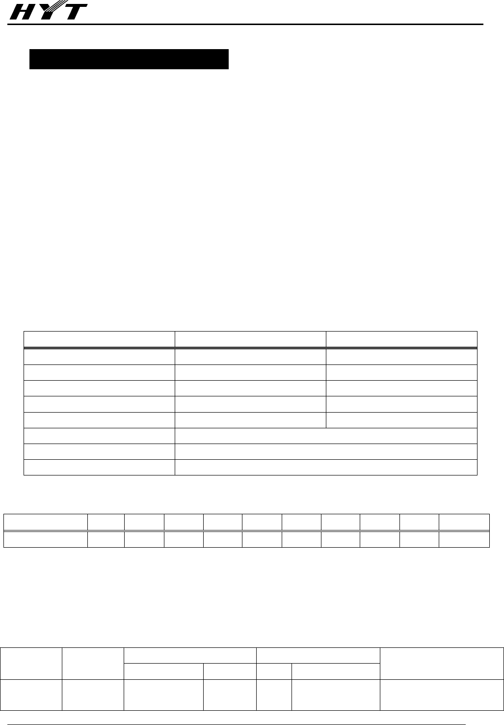
Removing and Installing the Top Cover
1. using a screwdriver to Remove the seven screws (M3.0X6.0) that locking the top cover of ①
repeater, shown as Figure 1.
2. Remove the top cover , shown as Figure 1.②
3. Install the top cover as reverse steps.
Figure 1
Removing and Installing the Front Panel
1. Press the 6 latches that locking the front panel to the housing to separate and remove them from
the housing , s①hown as Figure 2.
2. Remove the front panel shown as Figure 2, and pull out the two ②set of jumper wires, two repeater
cables, accessory connector cable, and connecting cable of the DC power indication LED.
3. Install the front panel as reverse steps.
Figure 2
2
1
1
1
1
1
1
1
2
1
1
1
1
TR-800 Service Manual
-38-
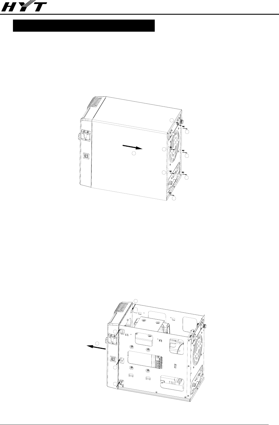
Removing and Installing the Control Panel
1. Remove the Volume Control knob ① shown as Figure 3.
2. Remove the nut using a special spanner, shown as Figure 3. ②
3. Remove the six screws (ST3.0X8.0) that secure the control panel using a screwdriver, sho③wn as
Figure 4.
4. Gently press and remove the RJ45 port from the front panel, then pull out the speaker cable to ④
remove the controller PCB, shown as Figure 4.
5. Install the control panel as reverse steps.
Figure 3 Figure 4
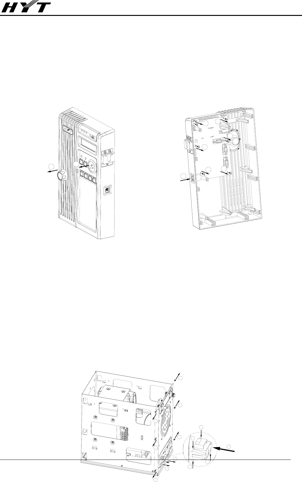
Removing and Installing the Rear Plate
1. Pull out the ATO fuse , shown as Figure 5.①
2. Press the spring latch located on the two ②edges of the DC socket, and push the DC socket into
the housing to separate the socket from the rear plate , shown as Figure 5.③
3. Remove the seven screws (M3.0X6.0) that secure the rear ④plate using a screwdriver, shown as
Figure 5.
4. Remove the two RF cables of both radios, and connecting cable of the fan, then remove the 3 power
jumper cables that connecting AC socket with switch power, using a screwdriver, and that’s all for
you to get prepared to remove the rear plate.
5. Installing the rear plate as the reverse steps.
2
1
4
3
3
3
3
3
3
4
4
4
3
2
2
2
2
1
4
4
4
4
TR-800 Service Manual
-39-
Figure 5
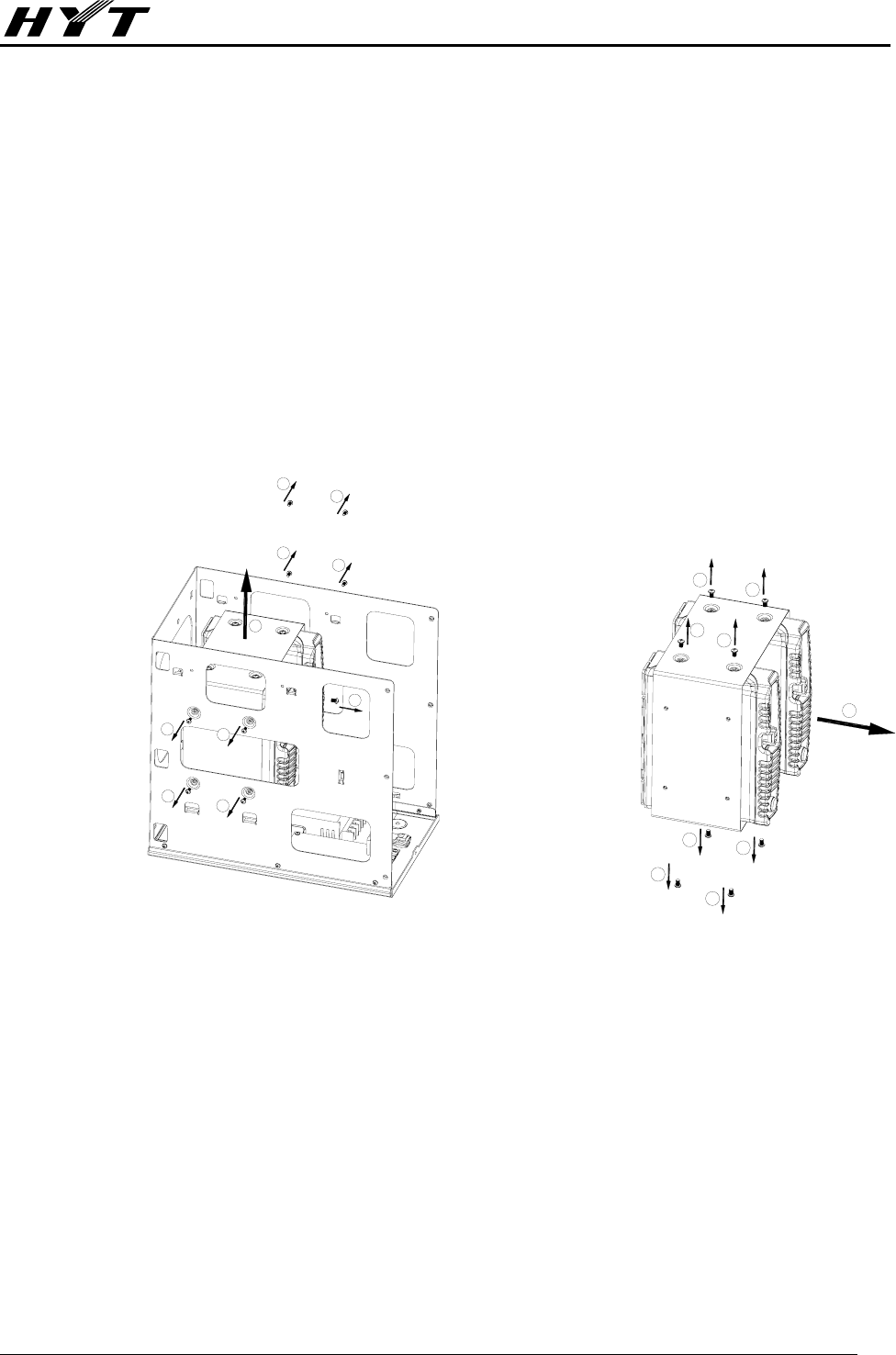
Removing and Installing the Radio
1. Remove the screw (M4.0X6.0) that secure the ①thermistor sensor using a screwdriver, shown as
Figure 6.
2. Remove the eight screws (M3.0X6.0) that secure the bracket of radio using a screwdriver, shown ②
as Figure 6.
3. Remove the bracket ③ shown as Figure 6, and remove the 2 signal cables and 2 power cables of
both radios.
4. Remove the eight screws (M4.0X6.0) that secure both radios using a screwdriver, and then ④
remove both radios , shown as Figure 7.⑤
5. Install both radios as the reverse steps.
Figure 6 Figure 7
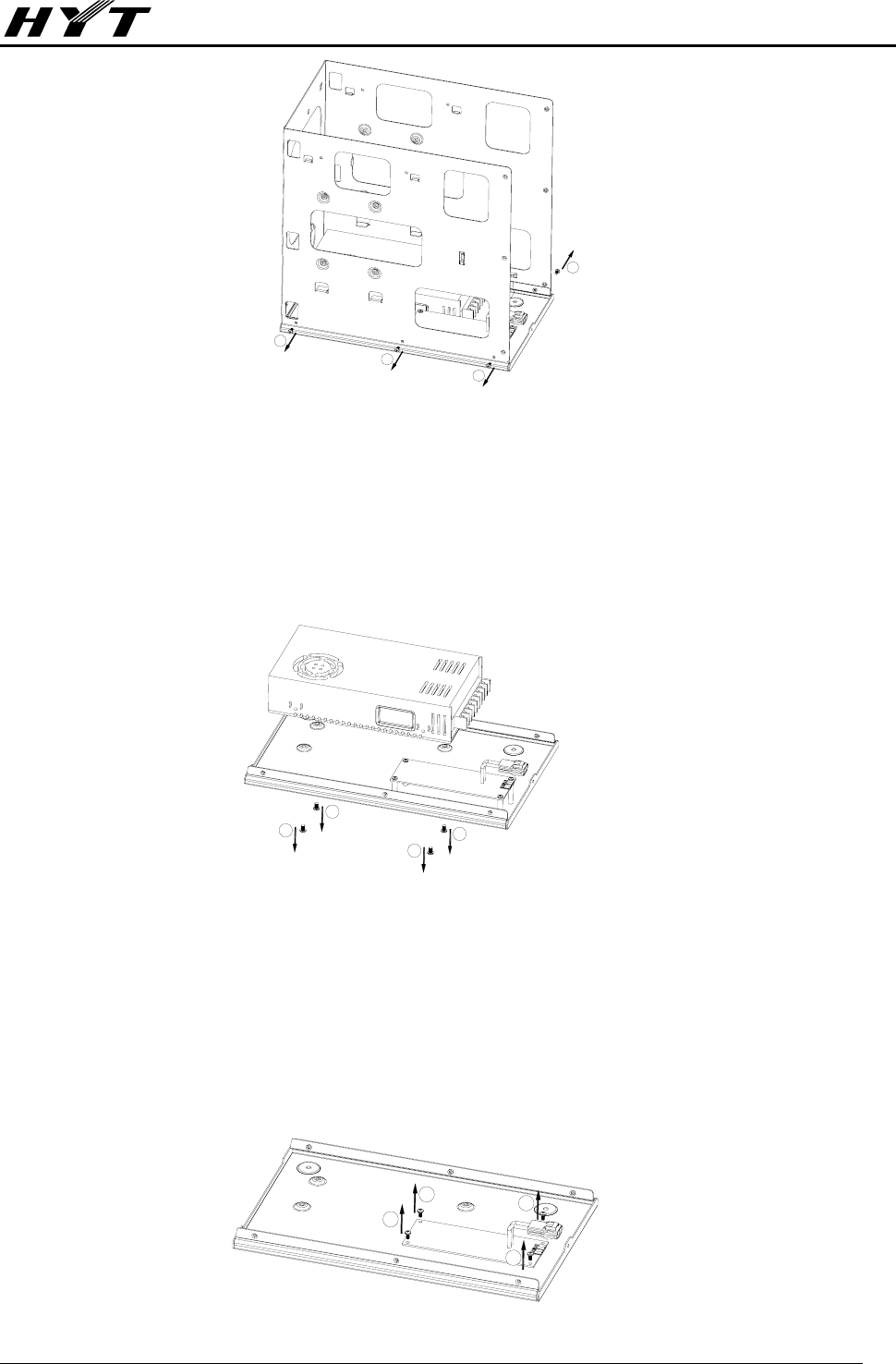
Removing and Installing Housing
1. Remove the six screws (M3.0X6.0) that secure the housing using a screwdriver, to remove the
housing ①, shown as Figure 8.
2. Install the housing as the reverse steps.
3
1
2
2
2
2
2
2
2
2
5
4
4
4
4
4
4
4
4
TR-800 Service Manual
-40-
Figure 8
Removing and Installing Switch Power
1. Remove the four screws (M4.0X6.0) that secure the switch power using a screwdriver, to remove the
switch power ①, shown as Figure 9.
2. Install the switch power as the reverse steps.
Figure 9
Removing and Installing the Power Management PCB
1. Remove the four screws (M3.0X6.0) that secure the power management PCB using a screwdriver,
to remove the power management PCB ①, shown as Figure 10.
2. Install the power management PCB as the reverse steps.
Figure 10
1
1
1
1
1
1
1
1
1
1
1
1
TR-800 Service Manual
-41-
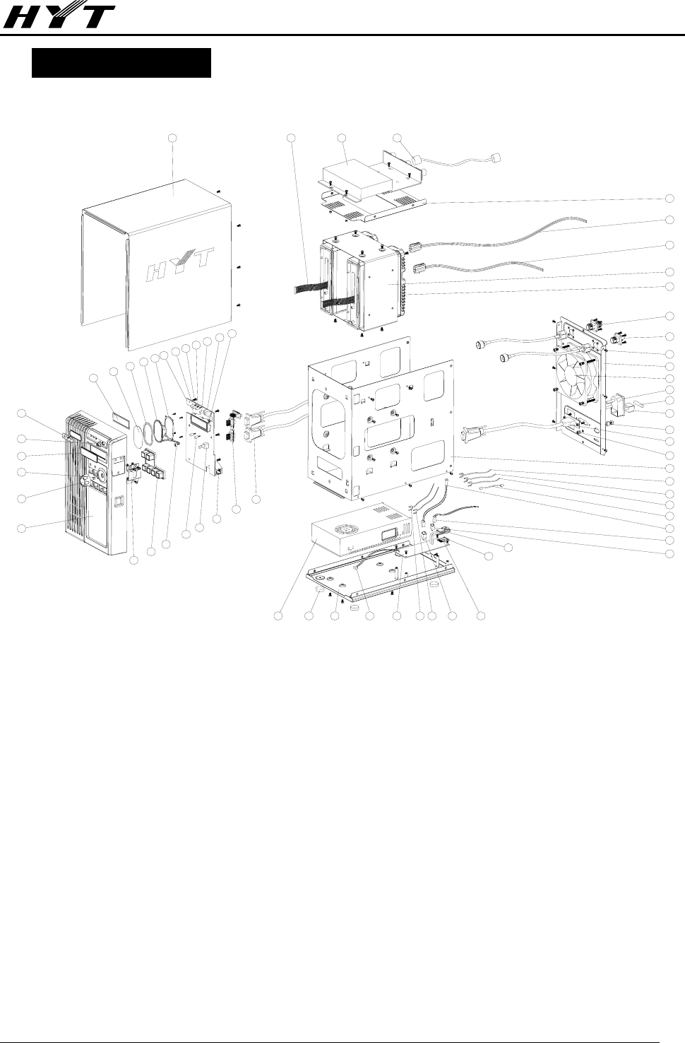
Exploded View
A
B
B
B
C
CC
DD
DD
E
E
E
E
F
F
F
F
F
F
F
F
F
F
F
F
F
F
F
F
F
F
F
FF
F
F
F
G
G
G
G
G
G
B
B
B
B
H
H
HH
H
H
H
H
H
H
H
I
I
I
I
I
J
J
J
J
CC
CCC
C
1
2
3
4
5
6
78910 11 12 13 14 15 16 17 18
19
21
22
23
24
25
26
27 28 29 30
31
32
33
34
35
36
37
38
39
40
41
42
43
44
45
46
47
48
49
50
53
54
55
56
5759606162636465
51
52
58
20

TR-800 Service Manual
-42-
TR-800 Parts List 2
No. Material No. Material Name Qty.
A 7207002200000 Nut M7.0*2.2mm 1
B 7203002400000 Nut M3.0*2.4mm 9
C 7103008001010 Machine screw M3.0*8.0mm 13
D 7102007020000 Self-tapping screw ST2.0*7.0mm 4
E 7103008020000 Self-tapping screw ST3.0*8.0mm 6
F 7103006001000 Machine screw M3.0*6.0mm 34
G 7103008001020 Machine screw M3.0*8.0mm 8
H 7104006000000 Machine screw M4.0*6.0mm 13
I 7204003001000 Nut M4.0*3.0mm 5
J 7104045000000 Machine screw M4.0*45.0mm 4
1 6000220000000 Front panel 1
2 6000221000000 Volume control Knob 1
3 6201066000000 Inner liner knob 0.20mm 1
4 6000232000010 LCD lens 1
5 6000222000000 SETUP button 1
6 5403000000040 HYT LOGO aluminum 1
7 7500068000000 LCD sponge 1
8 7400048010000 grill cloth 58*35mm 1
9 6100182000000 speaker 1
10 5001020000000
Speaker 16Ω 7W D:35mm 1
11 6201176000000
speaker tabletting 1
12 1302008000000 control board 1
13 3307110600020 LED L-483IDT red 1
14 3307110600010 LED L-483GDT green 1
15 3307110600050 LED L-483EDT orange 1
16 3307110600030 LED L-483YDT yellow 1
17 4301080000040 Momentary contact switch 1
18 5110000000110 LCD Module TM-800 1
19 4210400000100 repeater cable 2
20 5202015200000 HDB15/F socket (DIP) 3
21 5204008000000 RJ45 socket 1
22 4302030000040 Channel selector 1
23 3307990000080 LED LT5CB4-81-XA400714 ultra bright blue 2
24 4210080000700 Connecting cable of speaker (with 2 Pin plug) 2-core 2
25 6100135000000 silica rubber key 1
26 6201197000000 SM07 Hook 1
27 6201166000000 top cover 1
28 4200200000000 jumper cable 2

TR-800 Service Manual
-43-
29 Optional Duplexer 1
30 4220300000200 RF cable 1
31 6201171000000 duplexer bracket 1
32 4200400000200 power cable 1
33 4200250000200 power cable 1
34 6201170000000 bracket 0.8mmSECC 1
35 Optional main radio (Slave radio) 2
36 4408100002000 RF adaptor 1
37 4408100003000 RF adaptor 1
38 4220250000100 RF cable 2
39 6201168000000 rear plate 1
40 5401000000050 DC fan 12Vdc 0.9A 1
41 5205000000240 AC socket L46.80*W27.40mm 3pin 1
42 4099000000150 Cartridge fuse 1
43 4399010000000 Power switch 1
44 7104008000000 GND lug 1
45 4210400000200 T expansion signal cable 1
46 6201192000000 spring lock washer 5
47 6201169000000 housing 1
48 4210250000000 DC jumper cable #14 250mm red 1
49 4210250000100 DC jumper cable #14 250mm black 1
50 4210250000200 DC jumper cable #14 250mm yellow 1
51 4210250000300 DC jumper cable #14 250mm green 1
52 3003991040010 Surface temperature sensor 1
53 4200050000000 power cable of fan (2 pin with plug) 50mm 1
54 5202002100000 Socket 2pin 1
55 5204002000000 DC power socket 1
56 4002000000030 ATO Fuse 2
57 4002000000040 ATO Fuse clamper 2
58 5202002100100 Pin socket 3
59 4200250000000 DC power cable #14 250mm red 1
60 4200250000100 DC power cable #14 250mm black 1
61 1302008000010 Power supply board 1
62 4200400000010 Connection cable 1
63 6201167000000 Base tray 1
64 7500147000100 Foot 4
65 1603S24000010 Switch power 1
TR-800 Service Manual
-44-
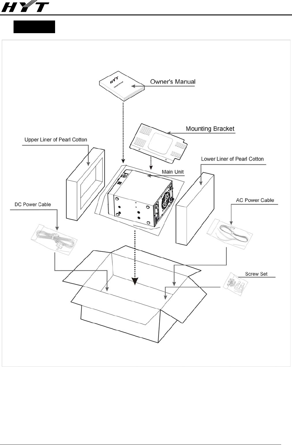
Packing
TR Service Manual
45
Specifications
General
Frequency range (Unit: MHz) VHF:136MHz~174MHz;U5:350MHz~400MHz
U1: 400MHz~470MHz; U2: 450MHz~512MHz
Channel capacity 512
Channel spacing 25KHz / 12.5KHz
Power supply requirement 13.8 V DC±20% / 88-264V AC 50/60Hz
Duty cycle 25W(100% Continuous) / 50W(VHF)45W(UHF)(50% Intermittent)
Power consumption
<1.8A Standby
<2.5A Receive
<13A @ 50/45W Transmit (13.8V dc)
Operating temperature range -25℃ ~ +60℃
Dimensions 190mm(W)×310mm(H)×362mm(D)
Weight 11kg
Receiver
Sensitivity <0.35uV@12dB SINAD
Adjacent channel selectivity ≥70dB(Wide) ≥60dB(Narrow)
Intermodulation response
rejection ≥70dB
Spurious response rejection ≥75dB
Rated Audio Output Power 5W(Int.) 12W(Ext. @ 4Ω)
Rated Audio Distortion ≤3%(3W) ≤10%(5W)
Frequency stability ±2ppm@ -25℃ ~ +60℃
Transmitter
Carrier output power
(Conducted) 25W / 50W(VHF) 45W(UHF)
Spurious emission ≤ -36dBm (below 1GHz)
Max. Frequency deviation 5KHz(Wide) / 2.5KHz(Narrow)
FM Hum and Noise ≥45dB(Wide) ≥40dB(Narrow)
Audio harmonic distortion ≤3% @ 60% Dev.
Frequency stability ±2ppm@ -25℃ ~ +60℃
All Specifications are subject to change without notice due to continuous development.