Hafele America 102 RF Door Lock User Manual PW3102 User Information
Hafele America Co. RF Door Lock PW3102 User Information
UserManual.wiki
>
Hafele America
>
102 User Manual
PW3102 User Information
Navigation menu
Upload a User Manual
Namespaces
Wiki Guide
HTML
PDF
Info
Views
User Manual
Discussion / Help
Navigation
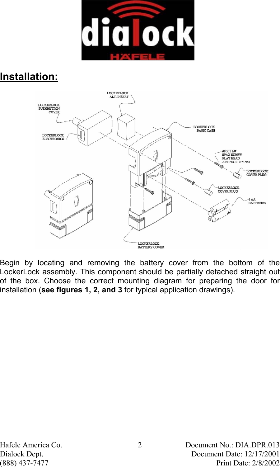

![Hafele America Co. 7 Document No.: DIA.DPR.013 Dialock Dept. Document Date: 12/17/2001 (888) 437-7477 Print Date: 2/8/2002 After the LockerLock unit has been attached to the door install four AA batteries per the + and – designations on the LockerLock body. Replace battery cover. The two extension hooks on the cover will have to be pressed in as the cover is reseated. Make sure the cover is secured. The unit is ready to be programmed for operation. Programming: Setting unit into Simple mode Read these sections through completely before powering the system Learning of Addition and Deletion Key-Sticks As soon as the system is activated (the system is activated by depressing fully the push button with a finger), a green LED light flashes for a several seconds. This light as well as the red LED are located in the small plastic window on the back side of the unit (center of the LockerLock unit on the side opposite the push button). The red LED light flashes, also for several seconds. These are the two learning phases for the addition and deletion key-sticks. During the time when the green LED flashes, the green addition key-stick must be presented to the LockerLock push button by depressing the button for a second. During the time when the red LED flashes, the red deletion key-stick must be presented to the LockerLock push button by depressing the button for a second. After these two key-sticks have been initialized, user keys can be added or deleted in the LockerLock memory. If the reader push button is pressed on the LockerLock without having the green and red key-sticks available, you must wait for the learning process to be completed. Afterwards, the push button on the LockerLock must be pressed again, when the keys are accessible. IMPORTANT!!!! IN STAND ALONE [SIMPLE] (GREEN AND RED) PROGRAMMING, THE FIRST TWO TRANSPONDERS SHOWN TO A FLASHING GREEN AND RED LED BECOME THE ADDITION AND DELETION KEYS RESPECTIVELY. CARE SHOULD BE TAKEN TO MAKE SURE THE PROPER KEYS ARE PROGRAMMED!!!!!](https://usermanual.wiki/Hafele-America/102/User-Guide-226050-Page-7.png)