Hafele America 104 Wall-mounted door and lock control User Manual PW3104
Hafele America Co. Wall-mounted door and lock control PW3104
PW3104 User Manual
Wall Terminal
Mounting instructions

Mounting instructions
engl. 15
Technical information
All wall terminals are supplied in the basic method of operation.
With this method of operation, electronic keys are given access
authorisations directly at the wall terminal with a special programming
key stick (green). Up to 100 electronic keys can be allocated per wall
terminal. With a clearing key stick (red), the access authorisations of an
authorised electronic key can be withdrawn directly at the wall terminal.
If a different method of operation needs to be chosen, please contact
your Dialock sales office.
Technical data
Voltage supply 10 - 12 VDC, 8 - 10 VAC
Continuous current intake <200 mA
Peak current intake 250 - 400 mA, depending on
number of relays
Number of relays 1 - 3
Contact load relay
Voltage on contact max. 60 VDC, max. 125 VAC
Current on contact max. 2 A, (short term)
Contact rating max. 30 W, max. 60 VA
Continuous current max. 1 A
Data retention in case of power cut 10 years
for external
sector for internal
sector
Protection level
Reader module IP 68 IP 54
Control electronics module IP 66 IP 66
Temperature-operating range
Reader module -20 - 80 °C 0 - 60 °C
Control electronics module 0 - 60 °C 0 - 60 °C
relative air humidity (non
condensating)
0 - 95 % 0 - 95 %
Mounting instructions
16 engl.
Range of application
Wall terminals control electric door openers and motor locks for:
external or internal doors
or:
automatic roller shutters
barriers
appliances and installations, such as goods dispensers or sun beds
can also be monitored via wall terminals.
Important characteristics:
suitable for surface- and flush fitted installation
can be used as cash terminal
can be connected to a central unit (PC) via online adapter
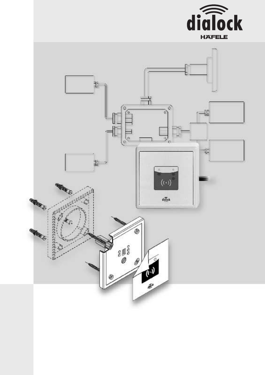
Supply schedule
The configuration supplied, consists of:
reader module with approx. 2.5m long, round, flat band cable and
plug for connection to the control electronics module
front foil to apply onto the reader module
spacer plate for the surface installation of the reader module
control electronics module with one relay (optionally up to 3)
screw fixings for the casing of the control electronics module
PG-9-screw fixing for connecting the flat band cable to the control
electronics module
feeder implement to connect cables to the control electronics module
spare plug for the flat band cable
Mounting instructions
engl. 17
Installation
The following steps are necessary for the installation:
install the reader module
install the control electronics module
electrical installation
6 5 4
3
10
7
8
9
1
2
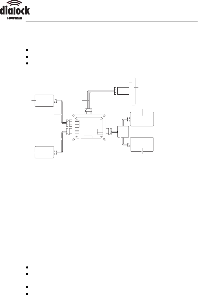
1 flat band cable (round, shielded)
2 reader module
3 element to be switched (appliance)
4 power supply for element to be switched (appliance)
5 distributor
6 control electronics module
7 power supply for control electronics module
8 conductor
9 interface cable (optional)
10 online-adapter (optional)
During the planning phase, the following installation measures need to
be considered:
internal or external installation of the modules
exact location for the modules to be installed, considering the
position of the elements to be switched (i.e. door lock, barrier)
surface- or flush fitted installation of the modules
connection of the wall terminals to a central unit (PC) via online-
adapter
Mounting instructions
18 engl.
Install the reader module
Preparations:
drill a hole into the wall for the connecting cable between the reader
module and the control electronics module. Lay a protective pipe
with an internal diameter of at least 12 mm or a cable channel.
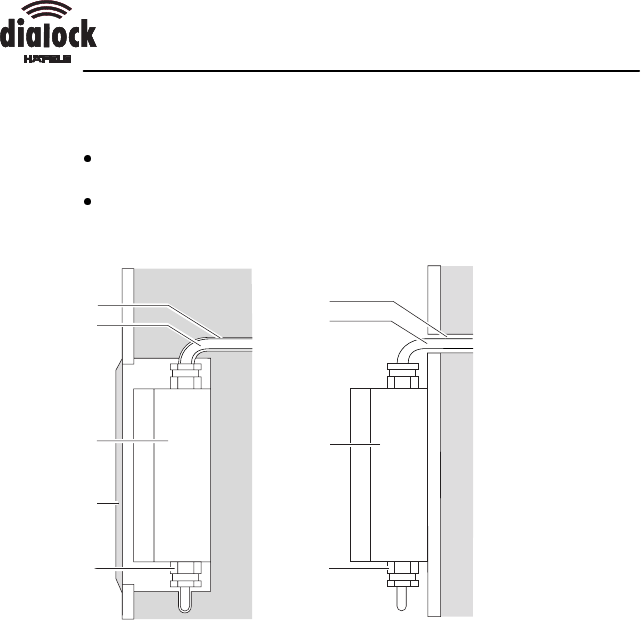
flush fitted installation: install a flush fitted container with a diameter of
70 mm and a minimum depth of 60 mm.
surface installation: drill a 25 mm diameter hole and minimum 48 mm
depth for the PG-9-screw fixing.
12
3
min. 48
4
5
min. 25
12
3
min. 60
4
70
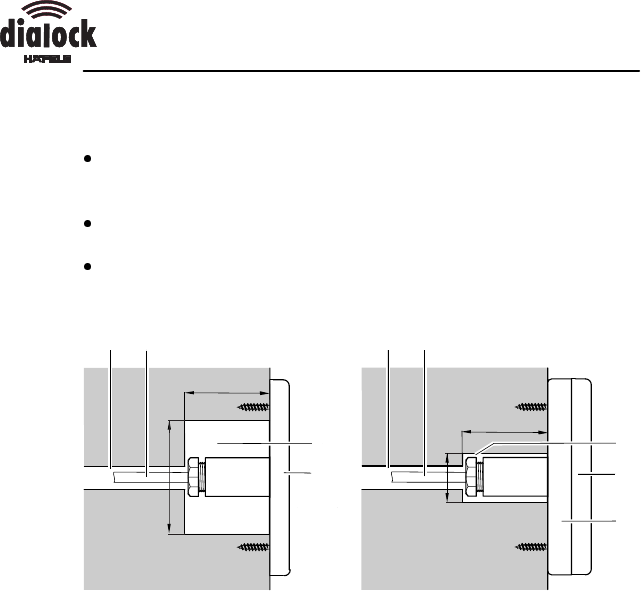
Flush fitted installation (left) and surface installation (right) of the reader module
1 protective pipe (internal diameter min. 12 mm)
2 cable (diameter = 8 to 9 mm, length = 2,5 m)
3 flush fitted container, resp. drilling for PG-9-screw fixing
4 reader module
5 spacer plate
1. for flush fitted installation: drill a 12 mm diameter hole in the centre
of the flush fitted container.
2. for flush fitted installation: remove the spacer plate of the reader
module.
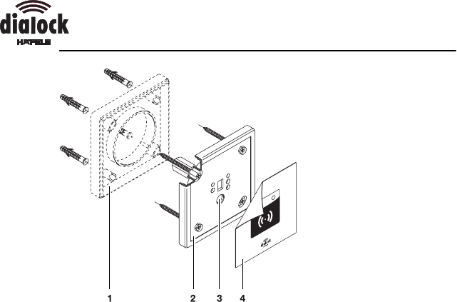
Mounting instructions
engl. 19
1 spacer plate
2 reader module
3 10-mm-hole
4 front foil
3. For installation on brick work:
Ødrill holes for 6 mm dowels into the wall to fix the reader module.
Øfix the reader module with 4 Hospa screws, 4x50 mm. Make
sure, that the 10 mm hole is at the bottom and that the screws
do not protrude over the countersinkings.
4. For installation on metal:
Ødrill four holes for an M4 thread.
Øcut the thread
Øfix the reader module with four countersunk screws. Make sure,
that the 10 mm hole is at the bottom and that the screws do not
protrude over the countersinkings.
5. guide the free end of the cable through the hole in the brick work to
the control electronics module.
If the plug does not fit through the hole in the brick work:
Øcut off the plug.
Øloosen the PG-9-screw fixing and strip it off the cable.

Mounting instructions
20 engl.
Øguide the free end of the cable through the hole to the control
electronics module.
Øcut the cable to length.
Øre-fit the PG-9-screw fixing to the cable.
Øguide the flat band cable through the aperture in the spare plug,
such that the arrow on the plug is on the same side as the red
marking of the flat band cable (polarity!)
Øsqueeze the spare plug shut with water pump pliers or with
special squeezing pliers.
6. Apply the front foil onto the reader module. Line up the cut outs of
the front foil with the apertures in the reader module for coverage.
Mounting instructions
engl. 21
Install the control electronics module
Conditions:
cables and power supply for all appliances to be connected have
been laid
for flush fitted installation: a sufficiently large drilling has been
prepared
1
2
3
4
3
4
2
5
1
Flush fitted installation (left) and surface installation (right) of the control
electronics module
1 protective pipe (internal diameter min. 12 mm)
2 cable (diameter = 8 to 9 mm, length = 2,5 m)
3 control electronics module
4 connection for power supply
5 inspection flap
ØDrill four holes for 6 mm dowels into the wall to fix the control
electronics module.
Mounting instructions
22 engl.
Electrical installation
2
4
+
RxData
TxData
GND
RTS
CTS
NO
NC
COM
NO
NO
COM
COM
7
8
Input1
Input2
S-Input1
6
3
5
NC
NC
1
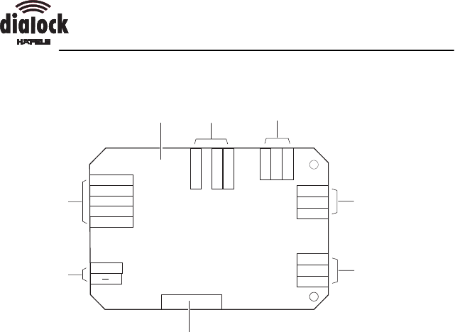
Occupancy schedule of the control electronics module
1 Plate of control electronics module
2 TTL-entrances, to be approached via a switch
3 relay 3 (optional)
4 relay 2 (optional)
5 relay 1
6 flat band cable connection to the reader module (pin bar)
7 supply voltage
8 serial RS-232-interface to the PC or online adapter
Mounting instructions
engl. 23
4 3
2
16
5
4 3
2
1
5
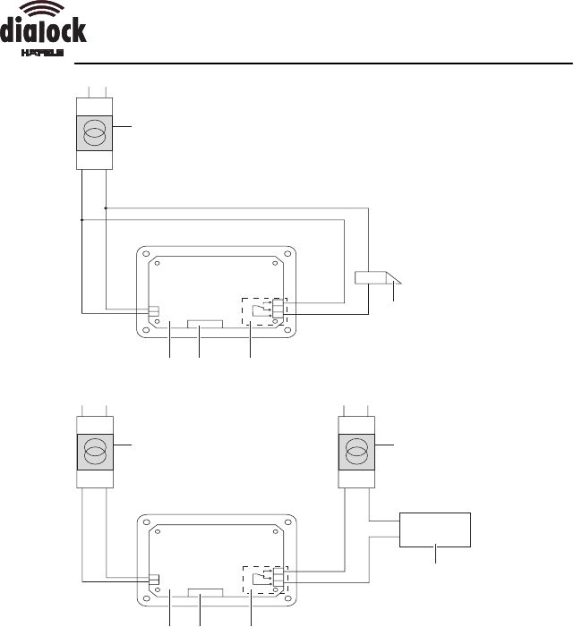
Switch example: joint (top) and separate (bottom) power supply for the
consuming device and the terminal
1 transformer (adapted to the voltage and output requirements of the
element to be switched)
2 element to be switched (appliance)
3 relay 1
4 connection for the reader module
5 plate of control electronics module
6 transformer (adapted to the voltage and output requirements of the
element to be switched)

Mounting instructions
24 engl.
Danger of death through an electric shock!
ØMake sure, that the electrical installation is carried out by qualified
personnel.
Destruction of the relay contacts when operating the door
opener with direct current!
ØUse a free running diode.
1. turn off the fuses of all consuming devices to be connected and the
power supply for the wall terminal!
2. make sure, all cables are voltage-free.
3. drill holes to feed the cables of the PG-9-screw fixings for the
reader module, power supply, elements to be switched and if
necessary the cable of the online adapter into the casing of the
control electronics module.
4. cut the cable to length.
5. slide the PG-9-screw fixings onto the cable to be connected.
6. fix the casing of the control electronics module to the wall with four
Hospa-screws 4 x 50 mm.
7. guide the cables through the holes in the casing.
8. slide the nuts of the PG-9-screw fixings onto the cables and tighten
the PG-9-screw fixings.
Mounting instructions
engl. 25
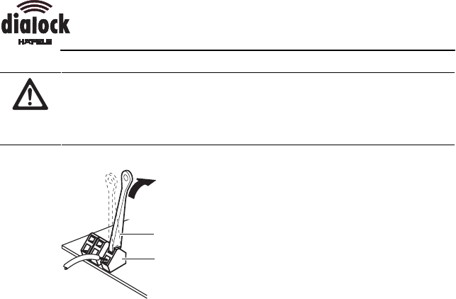
The plate is destroyed, if inappropriate tools are used!
ØConnect the cables of the appliances to be connected only with the
enclosed feeder implement.
1
2
1 feeder implement
2 contact clamp
9. open the contact clamps with the feeder implement.
10. slide the cable into the contact apertures.
11. remove the feeder implement.
12. insert the cable of the sensor head into the pin bar.
13. fix the casing lid onto the casing with the enclosed plastic screws.
14. if the control electronics module is flush-fitted: install an inspection
flap.
Mounting instructions
26 engl.
Initiation for basic method of operation
Allocate the programming and deletion key-stick
In the basic method of operation, the programming and deletion key-
sticks are allocated during the initiation.
This step is only possible straight after the installation of the supply
voltage for the wall-terminal.
Prevent the misuse by unauthorised persons!
ØKeep the programming and deletion key-sticks in a safe place, as
these can allocate and withdraw locking authorisations to/ from an
electronic key.
1. Have the green programming key-stick and the red deletion key-
stick ready.
2. If there is voltage already at the wall terminal, interrupt the voltage.
3. Produce voltage supply.
The green indicator (LED) flashes for a few seconds.
4. Place the green programming key-stick in front of the reader
module, whilst the green LED flashes.
The red indicator (LED) flashes briefly to confirm the successful
allocation.
5. Place the red deletion key-stick in front of the reader module, whilst
the red LED flashes.
The red indicator (LED) is illuminated.
If errors have occurred during the allocation:
Ødisconnect and re-connect the voltage.
ØRe-allocate the programming and deletion key-stick.
If continuous errors occur:
Øcontact your Dialock-sales office.

Mounting instructions
engl. 27
Brief operating instructions for basic method of operation
Allocate access authorisations
1. Place the green programming key-stick in front of the reader
module.
The green indicator (LED) flashes.
2. Place the key to be introduced in front of the reader module within
5 seconds.
The green indicator (LED) flashes briefly.
The locking authorisation for the electronic key to be introduced has
been allocated.
3. Remove the introduced key.
If the red indicator (LED) is illuminated, the attempt has been
unsuccessful:
Ørepeat the allocation of the access authorisations.
4. Place the next electronic key to be introduced in front of the reader
module in intervals of 5 seconds.
Withdraw access authorisations
1. Place the red deletion key-stick in front of the reader module.
The red indicator (LED) flashes.
2. Place the electronic key to be deleted in front of the reader module.
The red indicator (LED) flashes briefly.
The access authorisations are withdrawn.
Withdraw the access authorisations of all electronic keys
If an electronic key has been lost and should no longer have locking
authorisations, all electronic keys have to be deleted at the reader
module. Afterwards, all electronic keys which should have access
authorisations, have to be re-allocated.
1. Place the red deletion key-stick in front of the reader module.
The red indicator (LED) flashes.
2. Place the green programming key-stick in front of the reader
module.
The red indicator (LED) flashes briefly.
3. All electronic keys, which need to retain the locking authorisation,
will be re-allocated with access authorisations.

Mounting instructions
28 engl.
How to operate the Wall Terminal
ØPlace the electronic key with locking authorisation in front of the
reader module at a distance of a few centimetres.
The green indicator (LED) lights up, the red indicator (LED) switches
off.
The element to be switched is activated, i. e. the door opener is
unlocked.
If the LEDs do not switch from red to green:
ØPlace the electronic key closer to the terminal.
If the LEDs still do not switch from red to green:
The electronic key has no access authorisation.
ØPlace the access authorised electronic key in front of the reader
module.
Mounting instructions 732.29.101
The reprint of the mounting instructions, even extracts, or copying of the illustrations and drawings as well
as copying of the layout are prohibited.
No liability is accepted for printing errors or errors occurred during the creation of the mounting instructions.
We reserve the right for technical changes and changes of availability.
Status 06.00
Copyright
Häfele GmbH & Co
Adolf-Häfele-Strasse 1 · D-72202 Nagold
Postfach 1237 · D-72192 Nagold
Telefon +49 (0) 74 52 / 95-0
Telefax +49 (0) 74 52 / 95-200
E-Mail: info@haefele.de · www.haefele.de
NOTICE: Any changes or modifications made to the Wall Terminal will void
the user's authority to operate this equipment in compliance with FCC
regulations.
NOTE: This equipment has been tested and found to comply with the limits
for a Class B digital device, pursuant to Part 15 of the FCC Rules. These
limits are designed to provide reasonable protection against harmful
interference in a residential installation. This equipment generates, uses and
can radiate radio frequency energy and, if not installed and used in
accordance with the instructions, may cause harmful interference to radio
communications. However, there is no guarantee that interference will not
occur in a particular installation. If this equipment does cause harmful
interference to radio or television reception, which can be determined by
turning the equipment off and on, the user is encouraged to try to correct the
interference by one or more of the following measures: Reorient or relocate
the receiving antenna. Increase the separation between the equipment and
receiver. Connect the equipment into an outlet on a circuit different from that
to which the receiver is connected. Consult the factory or an experienced
radio/TV technician for help.