Haier Esa412K Users Manual 1.FH10
General Electric Heat Pump 5200 P020110831595246434785
ESA412K to the manual d45765cc-82df-4460-8256-5107e24ed1fc
2015-01-23
: Haier Haier-Esa412K-Users-Manual-258928 haier-esa412k-users-manual-258928 haier pdf
Open the PDF directly: View PDF ![]() .
.
Page Count: 259 [warning: Documents this large are best viewed by clicking the View PDF Link!]

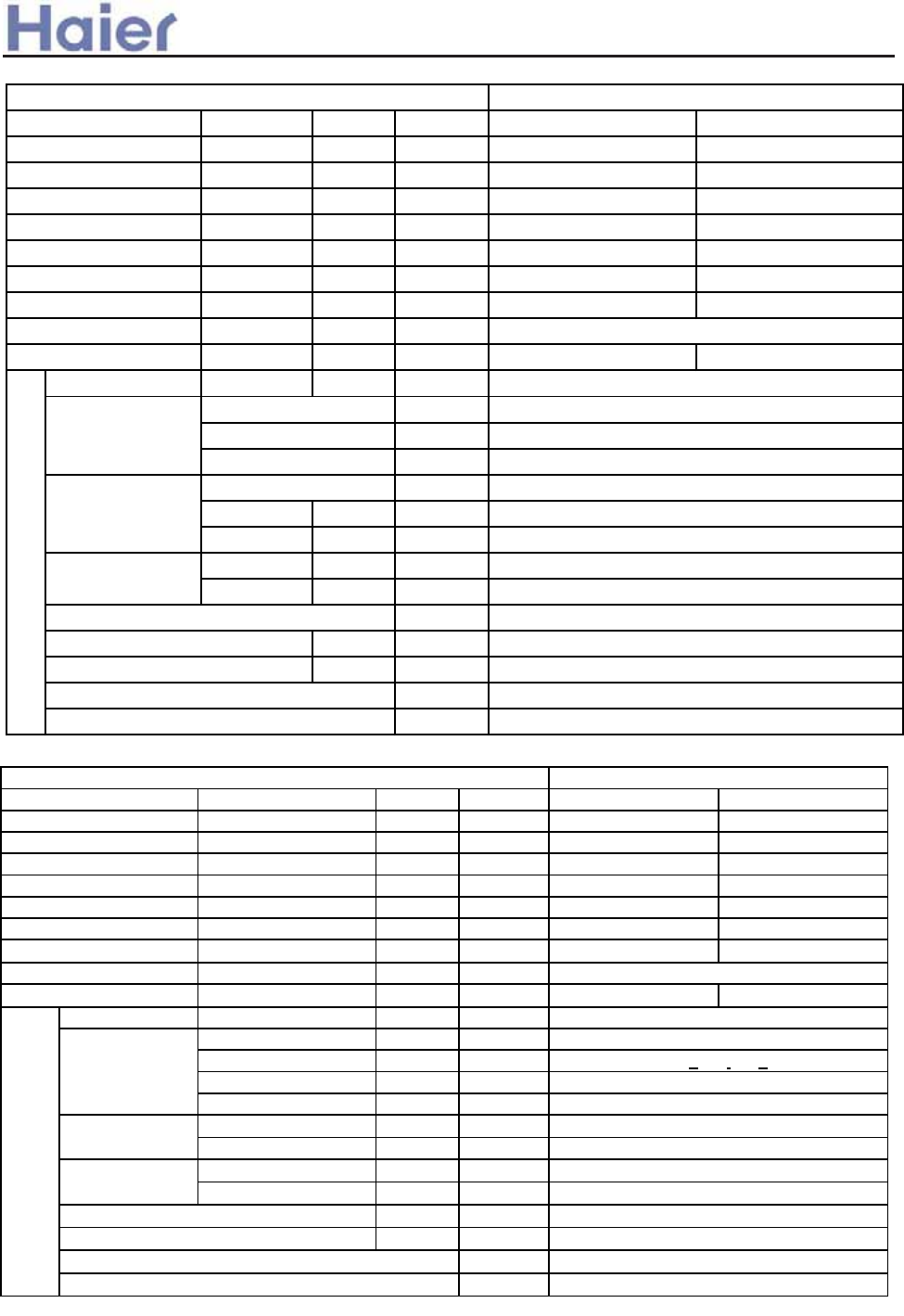
L@KOD>@ G<HN<F
CRZVb >_]]VbTZR\ <Zb >_^UZdZ_^Vb
6/P<Q ><LL@MM@ DH?IIK NHDM
>IHO@KMD=F@ DH?IIK NHDM
?N>M DH?IIK NHDM
><=DH@M MQJ@
P<FF GINHM@? MQJ@
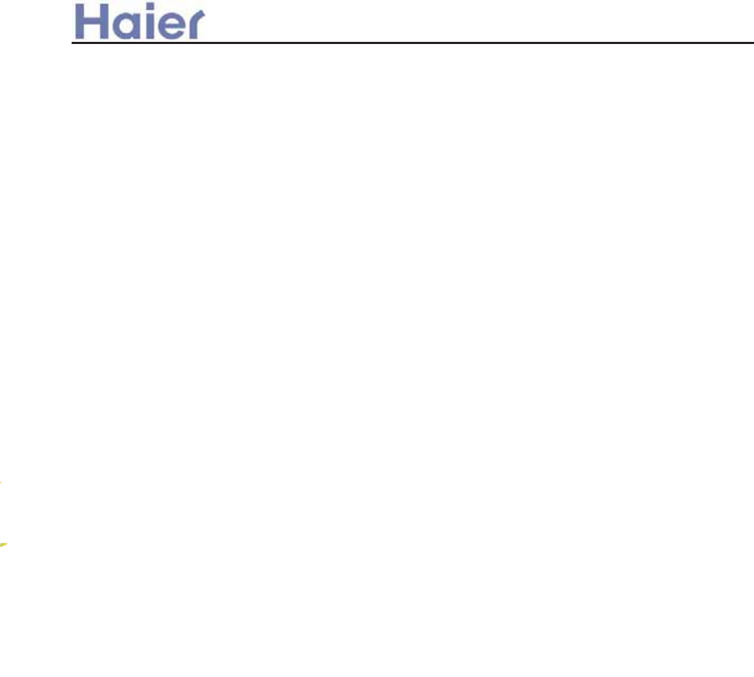
INM?IIK NHDM,3:222j82222=MN1Y-
N^ZdRbi c]Rbd cVbZVc
Version: 200703
>_]]VbTZR\ <Zb >_^UZdZ_^Vb
>IHM@HML
30 BV^VbR\ Z^W_b]RdZ_^
303 G_UV\ T_UV UVcTbZ`dZ_^
304 LVbZVc \Z^V e`
305 I`VbRdZ_^ dV]`VbRdebV bR^XV
306 Jb_UeTdc WVRdebVc
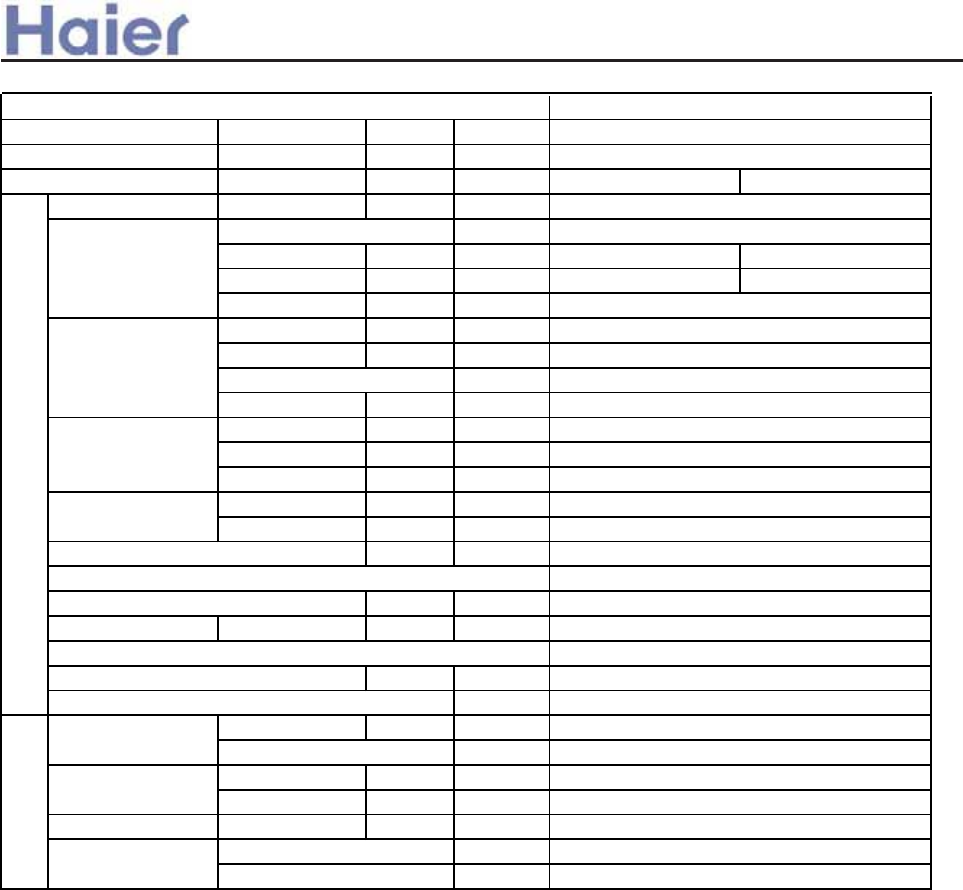
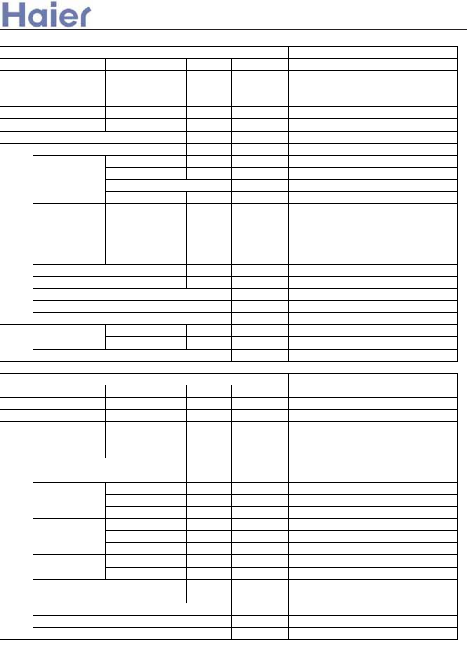
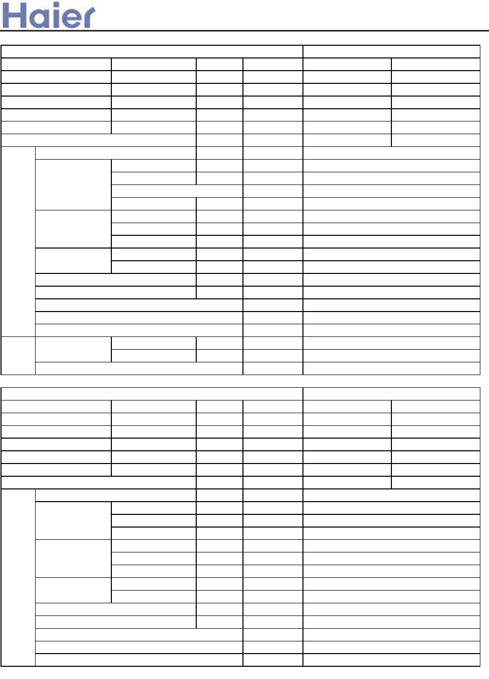
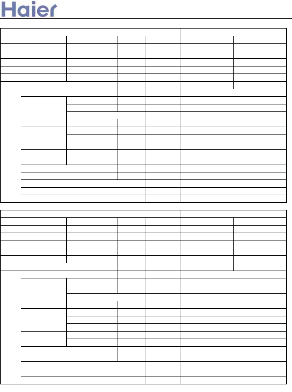
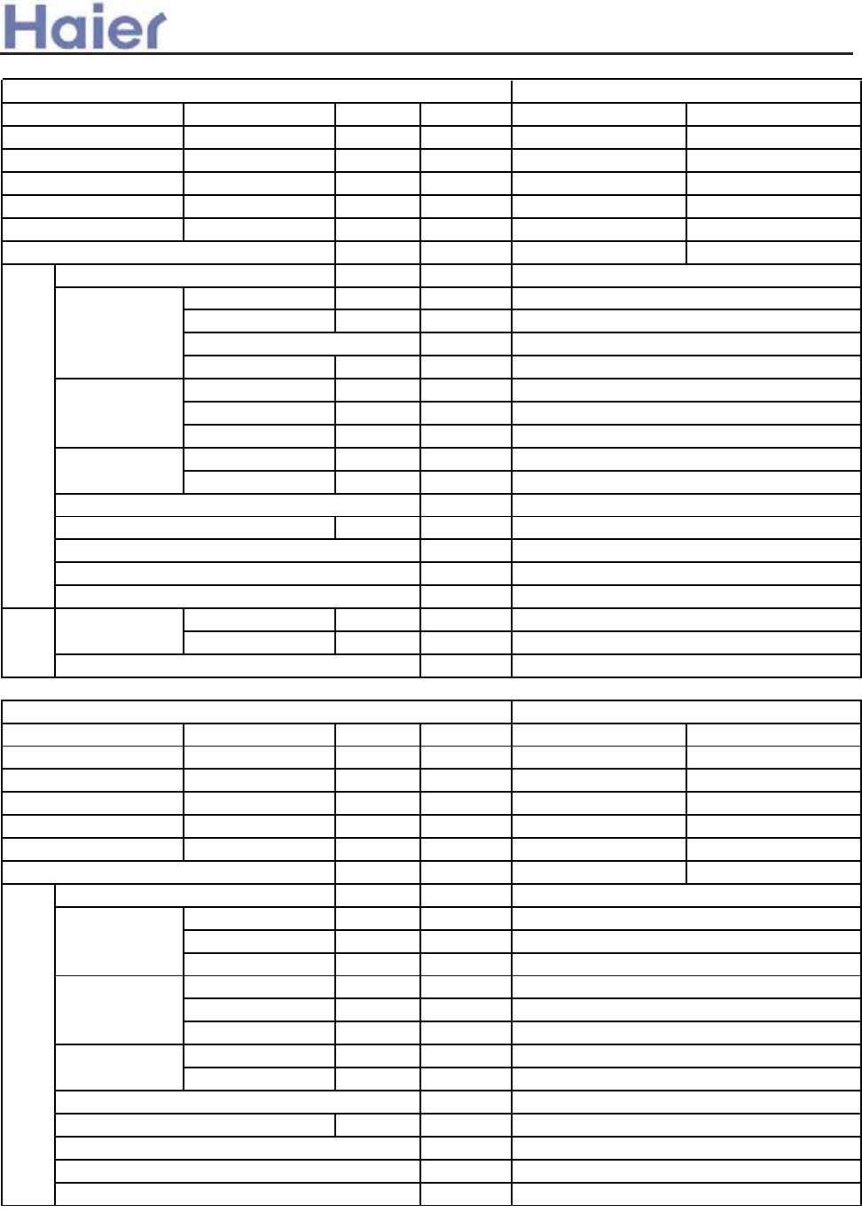
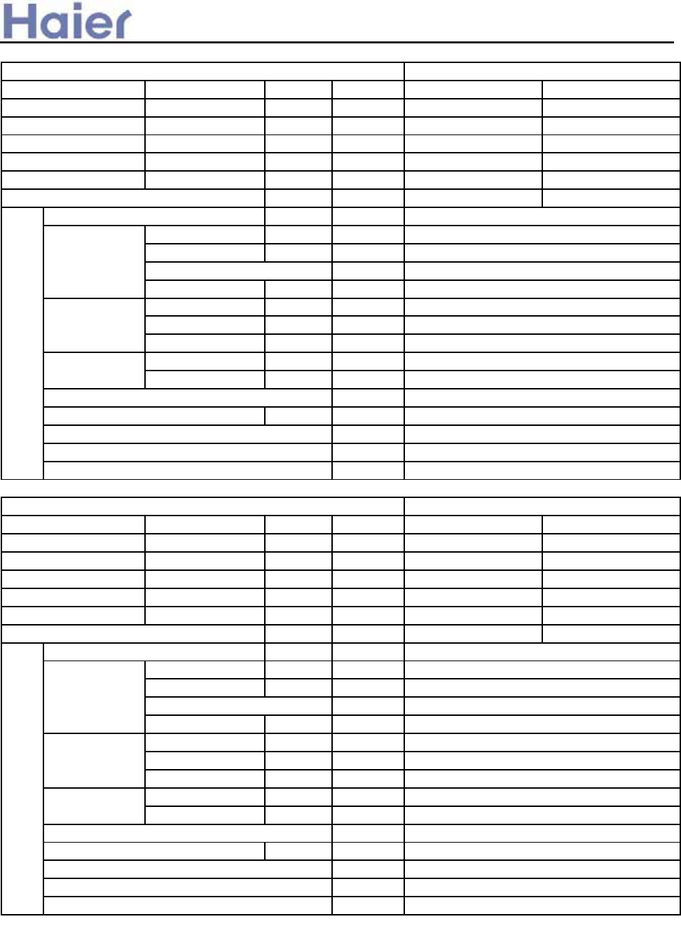
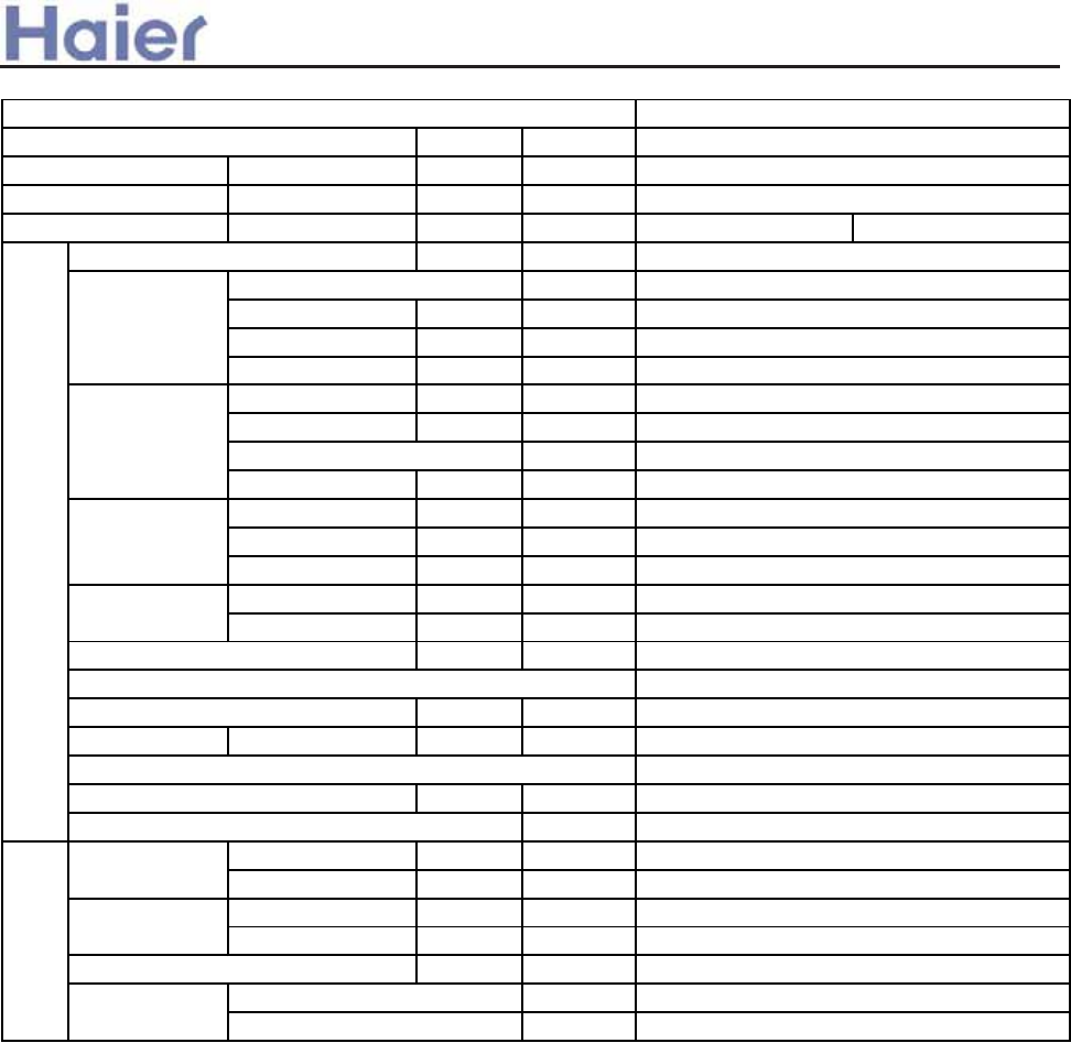
40 L`VTZWZTRdZ_^c
403 L`VTZWZTRdZ_^c W_b Z^fVbdVb e^Zdc
404 L`VTZWZTRdZ_^c W_b WZh WbVaeV^Ti e^Zdc
50?Z]V^cZ_^c
503 IedU__b e^Zd UZ]V^cZ_^
504 D^U__b e^Zd UZ]V^cZ_^
60 JRbdc ^R]V
70 KVWbZXVbR^d TZbTeZd
8 D^cdR\\RdZ_^ Z^cdbeTdZ_^
803 >RccVddV Z^U__b e^Zd ,<=3:j<=82-
804 >_^fVbdZS\V Z^U__b e^Zd ,<>3:j<>46-
805 >_^fVbdZS\V Z^U__b e^Zd ,<>4:j<>82-
806 >VZ\Z^X T_^TVR\VU UeTd di`V ,<?3:j<?46-
807 GVU @LJ UeTd Z^U__b e^Zd ,<?3:j<?6:-
808 CZXY @LJ UeTd Z^U__b e^Zd ,<?4:j<?82-
809 >RSZ^Vd Z^U__b e^Zd ,<J64j<J6:-
80: PR\\ ]_e^dVU Z^U__b e^Zd ,<L3:4<O@K<-
80; IedU__b e^Zd ,<N3:j<N82-
90 @\VTdbZT T_^db_\ We^TdZ_^c
903 AZhVU WbVaeV^Ti e^Zd
904 D^fVbdVb e^Zd
:0 @\VTdbZTR\ gZbZ^X UZRXbR]c R^U J>= `Y_d_
:03 D^fVbdVb _edU__b e^Zd
:04 AZhVU WbVaeV^Ti _edU__b e^Zd
:05 D^U__b e^Zdc
:06 LV^c_b TYRbRTdVbZcdZT
; ARZ\ebV T_UV R^U db_eS\VcY__dZ^X
;03 ARZ\ebV T_UV
;04 Mb_eS\VcY__dZ^X W_b Z^fVbdVb e^Zdc
;05 Mb_eS\VcY__dZ^X W_b WZhVU WbVaeV^Ti e^Zdc
5
5
6
7
;
;
3:
59
59
62
69
77
79
96
:6
:;
;7
327
333
342
357
357
358
5
348
342
363
37 7
37
79
9
32
37
89
9
9
324
38 4
Appendix - Controllers 179
-3-
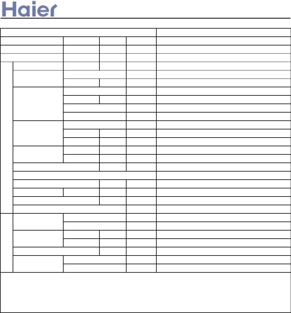
>_]]VbTZR\ <Zb >_^UZdZ_^Vb
30BV^VbR\ Z^W_b]RdZ_^
vsv 7SHIP GSHI HIWGVMTXMSR
T_UV < L 3: 4 <
GSSPMRK
GETEGMX]
[EPP X]TI
,
-
.
/
0
:
=
?
XLI ZEPMH RYQFIV QSVI
XLER XLSYWERH HMKMXEP vvurvvz@tzur{u2^ v
w
x
y
{
}
8
3
7
[MRHS[ X]TI
GEFMRIX X]TI
GEWWIXXI X]TI
GSRZIVXMFPI X]TI
HYGX X]TI
9YXHSSV ?RMX
HILYQMHMJM
IV
mPMXVI SV TMRXnXLI JMVWX
X[S RYQFIV
XLI JMVWX X[S RYQFIV
wwurwyu@tzu2^
vvzrwwu@tzur{u2^
wwurwyu@t{u2^
vvu@tzur{u2^
wwu@tzu2^
x}uryuu@t{u2^
yvz@tzu2^
x}uryuu@tzu2^
WMRKPI WTPMX YRMX SV
TEGOEKIH YRMX
X[S F] SRI
JSYV F] SRI
+
,
-
.
0
B
GSHI ERH QIERMRK +
JVII GSQFMREXMSR
m7<@ WIVMIWn
QYPXM WIVMIW
+
,
-
.
/
7
8
9
:
;
|
ETTIEVERGI
}
VIJVMKIVERX
LIEXMRK ERH GSSPMRK
<ww
<yu|-
<vxyE
GSSPMRK SRP]
ERH HILYQMJMIV
<vxyE
<ww
<yu|-
~
HIWMKR WIVMIW RYQFIV
+r1
2r;
<rD
JM\IH JVIUYIRG] ERH PMXXPI ETTPMERGI
.- MRZIVXIV X]TI
vu
GPMQEXI X]TI
>v
>x
>vqWYMXEFPI JSV EX rvz GSSPMRK
mGSSPMRKqLIEX TYQTnSV EX
rwu LIEXMRKmLIEX TYQTn
+
,
-
<yvuE
<yvuE
<vwx
<vwx
<yvu+?
xrTMTI
O@ K <
v
wxq y z{
EMV GSRHMXMSRIV TVSHYGX X]TI TVSHYGX WTIGMJMGEXMSR ZSPXEKI GSQFMREXMSR X]TI
GIMPMRK GSRGIEPIH
X]TI
EMV VIJVIWL
GETEGMX] XLVII F] SRI
KEW LIEX TYQT 1
+- MRZIVXIV X]TI
vsw ?RMXEV] =QEVX WIVMIW PMRI YT mo/++ FIPSRKW XS <yvu+ 9Rr9JJqo/<+ FIPSRKW XS <yvu+
.- 3RZIVXIVn
+?v}w+//++ +?wyw+1/++
+?x{w+3/++
+?x{8+3/++
+?y}8+3/++
+?{u8+3/++
+?yw8+6/++
+?x{w+2/<+
+?wyw+1/<+
+?v}w+0/<+
+?w}w+2/++
+?w}8+2/++
>a__WcU[S^ <[c>a`V[e[a`Wc
-4-
+=v}w+@/<+
JM\IH JVIUYIRG] WMRKPI YRMXqQYPXM WTPMX YRMX
-SSPMRK
2IEXMRK
3RHSSV
9YXHSSV
<EXIH 7E\MQYQ 7MRMQYQ
w| xw v}
v~ wx vy
xz yx vu
wy w{ {
wu w| vz
vysz rr rr
|wy r|
{v} rr
., -
A, -
., -
A, -
3RHSSV
9YXHSSV ., -
A, -
., -
A, -
+:y}w+5/++
+:yww+-/++
+.x{w+2/<+
+.v}w+7/<+
+.wyw+7/<+
+.x{w+7/<+
+.wyw+6/<+
+,v}w+-/<+ +,wyw+-/<+ +,x{w+-/<+ +-x{w+0/<+
+.v}w+6/++
+.wyw+6/++
+.wyw+7/++
+.w}w+7/++
+.x{w+7/++
+.y}w+7/++ +.w}w+2/++
+.x{w+2/++
+.y}w+2/++
+.{uw+2/++
vsx 9TIVEXMSR XIQTIVEXYVI VERKI
+,v}w+-/++ +,wyw+-/++
+,w}w+-/++
+,x{w+-/++
+,y}w+-/++
+,{uw+-/++
+-v}w+-/++
+-wyw+-/++
+-v}w+-/<+
+-wyw+-/<+
+-w}w+0/++
+-x{w+0/++
+-y}w+0/++
+-{uw+0/++
.TTQNSL
3JFYNSL
4SITTW
TZYITTW
=FYJI 8F]NRZR 8NSNRZR
x} yx w~
w*xy wz
y{ zy s{
xz x| ss
xv x} w{
wzt{ ss ss
}xz s}
|w~ ss
/- .
B- .
/- .
B- .
4SITTW
TZYITTW /- .
B- .
/- .
B- .
NS[JWYJW XNSLQJ ZSNYrXZUJW QT\ FRGNJSY YJRUtHTTQNSL
wtz ;WTIZHY KJFYZWJX
wtztw :ZYITTW KJFYZWJX
3060303<V`ae eZW ^fUZ Xc[W_V][Wc cWXc[YWcS_e K632S
?MJ FNW HTSINYNTSJW X^XYJR FITUYX YMJ LWJFYQ^ KWNJSIQ^ WJKWNLJWFSY =zwvFr\MNHM NX UWTYJHYN[J KTW YMJ
T_TSJ QF^JW FSI NX LTTI YT F[TNI YMJ JFWYM LJYYNSL \FWRJWt-JSJKNY KTW YMJ JS[NWTSRJSY 0
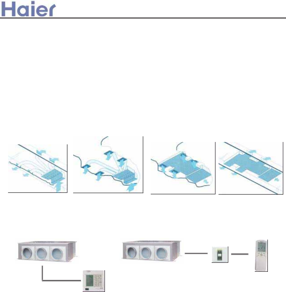
3060304 MZW f_[gWcdS] `feV``c US_ ^SeUZ h[eZ ^f]e[a]W ejaWd [_V``c f_[e
?MJ ZSN[JWXFQ TZYITTW HFS HTSSJHY YMJ HFXXJYYJ Y^UJuHTS[JWYNGQJ Y^UJuIZHY Y^UJuHJNQNSL HTSHJFQJI Y^UJ
NSITTW ZSNYXt.TS[JSNJSY YT IJXNLS FSI STY FKKJHY YMJ NSITTW IaHTWt
3060305 A]Wi[T]W S_V WSdj [_deS]]Se[`_
?MJ TZYITTW HFS RJJY YMJ MNLMJW WJVZJXY TK NSXYFQQFYNTSt1WTR YMJ XUJHNKNHFYNTSXr^TZ \NQQ KNSI KTW JFHM ZSNYr
MT\ QTSL FSI MT\ MNLM YMJ UNUNSL \NQQ GJr\MNHM \NQQ GJ HTS[JSNJSY KTW IJXNLS FSI NSXYFQQFYNTSt
3060306 Iae[`_S] dSXWej VWg[UWd S_V ^fUZ ^`cW acWU[d[`_ U`_ec`] VWg[UW
Ft,RGNJSY eW^aWcSefcW dW_d`cr HTNQ YJRUJWFYZWJ XJSXTW FSI HTRUWJXXTW YJRUJWFYZWJ RFPJ YMJ
YJRUJWFYZWJ HTSYWTQ FSI IJKWTXYNSL HTSYWTQ RTWJ UWJHNXJt
T0C[YZ1]`h acWddfcW dh[eUZ HFS KJJQ YMJ INXHMFWLNSL UNUJ UWJXXZWJ FSI XZHYNTS UNUJ UWJXXZWJ TS
YNRJ FSI UWJHNXJQ^t4K YMJ UWJXXZWJ NX YTT MNLM TW YTT QT\rNY\NQQ XYTU YMJ HTRUWJXXTW YT UWJ[JSY NYGJNSL
IFRFLJI KTW YMJ XFPJ TK UWJXXZWJt
U0F`h S^T[W_e U``][_Y \[e+4YNXFSTUYNTSFQ UFWY KTW YMJ X^XYJRt4K ^TZ \FSY YT WJFQN_J HTTQNSL RTIJ
\MJS YMJ J]YJWNTW FRGNJSY YJRUJWFYZWJ NX YTT QT\r^TZ HFS HMTTXJ NYt
V0>Mac`eWUe[`_+ KTW YMJ NS[JWYJW ZSNYrYMJWJ NX .? UWTYJHYNTSt4K YMJ X^XYJR HZWWJSY NX YTT MNLMrYMJ
JQJHYWNH X^XYJR \NQQ WJIZHJ YMJ KWJVZJSH^ TW XYTU YMJ ZSNY FZYTRFYNHFQQ^t
3060307 L[]W_e `aWcSe[`_
4S YMJ TZYITTW ZSNYr^TZ \NQQ KNSIrFRTSL YMJ UNUJ TW TZY TK YMJ HTRUWJXXTWrYMJWJ FWJ YMJ XTKY RFYJWNFQ YT
WJIZHJ YMJ STNXJ QJ[JQt-JXNIJXrKTW XTRJ ZSNYXrYMJ JQJHYWNH HTSYWTQ X^XYJR HFS FIOZXY YMJ STNXJ G^ KN]NSL
YMJ KWJVZJSH^t
>a__WcU[S^<[c>a`V[e[a`Wc
-5-

vsysw 3RHSSV JIEXYVIW
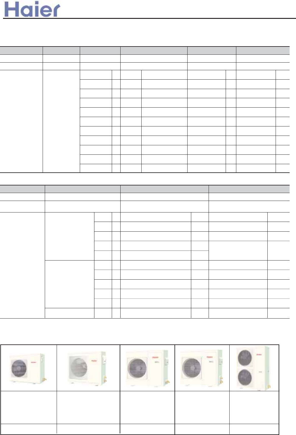
3060403 H_S\Vcd TRccVddV Z^U__b e^Zd
Es8I[ HIWMKRIH TERIP |uuo|uu [MXL XLI {uuo{uu GEWWIXXI YRMX
8I[ HIWMKRIH W[MRK PSYZIV [MXL XLI RSR WQSSXL WYVJEGIq[LMGL GER LSPH FEGO XLI GSRHIRWERX [EXIVs
8I[ HIWMKRIH JMPXIV PSGOq[LMGL [MPP JM\ XLI JMPXIV QSVI JMVQP] XLER FIJSVIs
+HSTXW XLI WXITTMRK QSXSVqKMZI XLI PSYZIV E PEVKIV W[MRK ERKIPs
8I[ JER [MXL FMKKIV HMEQIXIV JER FPEHIqWIRHMRK SYX PEVKIV EMV JPS[s
/PIGXVMG GSRXVSP FS\ MW PSGEXIH MR XLI YRMXqGSRZIRMIRX XS QEMRXEMRs
>LI GEWWIXXI MRHSSV YRMX EHSTXW XLI TERIP [LSWI HMQIRWMSR MW MHIRXMGEP XS XLEX SJ GIMPMRKqEJXIV MRWXEPPEXMSRq
XLI YRMX [MPP FI EGGSVHERX [MXL XLI HIGSVEXMSR HIGSVs
Fs0VII IPIZEXMRK TERIPqIEW] XS GPIER
>LI TERIP GER FI IPIZEXIH JVIIP] MJ XLI JMPXIV MW RIGIWWEV] XS FI GPIERIHq]SY GER QEOI XLI TERIP KS HS[R
XS XLI EHQMVIH TSWMXMSRqXLIR STIR XLI TERIP ERH HVE[ SYX XLI JMPXIV XS GPIERs
Gs0VIWL EMV SYXPIX HIWMKR
>LI YRMX MW IUYMTTIH [MXL XLI TVITEVIH JVIWL EMV SYXPIX mJSV +,u~_+,x{ YRMXWnq WS XLEX XLI GYWXSQIV GER
WIX XLI JVIWL EMV JYRGXMSR XS XLI YRMX EGGSVHMRK XS XLIMV S[R VIUYMVIQIRXs1VIEXP] MQTVSZI XLI VSSQ EMV
UYEPMX]s
Hs,YMPXrMR LMKL LIEH HVEMR [EXIV TYQT
.YI XS XLI MRXIVREP JPSEX W[MXGLqFYMPXrMR HVEMR TYQT GER HVEMR [EXIV EYXSQEXMGEPP] [LIR XLI GSRHIRWEXMSR
MW JYPP IRSYKL ERH RIGIWWEV] XS FI GPIERIHs>LI WXERHEVH LIEH LIMKLX GER FI YT XS {uuQQqVIEPM^MRK
XLI QSWX IJJIGXMZI [EXIV HVEMREKIs
Is0VII WIXXMRK SJ XLI yJPETW
>LI yr[E] GEWWIXXI YRMX LEW yW[MRK JPETW MR EPPsCSY GER WIX ER] SJ JPETW EGGSVHMRK XS XLI VIUYMVIQIRXs
/sKs]SY GER WIX SRI SV X[S JPET MR W[MXGLrSJJ TSWMXMSRs,YX XLI RSMWI PIZIP [MPP FI EJJIGXIHs
Js;YMIX STIVEXMSR
>LI YRMX MW IUYMTTIH [MXL XLI KVIEXP] TS[IVJYPqWQSSXLqERH YPXVE UYMIX QYPXMrFPEHI JERq[LMGL LEW XLI
MVVIKYPEV LIPM\qERH GER VYR MR WMPIRGIs
3060404 ?VTV^d T_^fVbdZS\V e^Zd
Es9TXMSREP MRWXEPPEXMSR QSHI
>LI GSRZIVXMFPI YRMX GER FI MRWXEPPIH RSX SRP] SR XLI JPSSV FYX EPWS XS XLI GIMPMRKq[LMGL GER FI HIXIVQMRIH
F] XLI LSWX JEZSV ERH XLI VSSQ H`GSVs3X MW QSVI GSRZIRMIRX XS WIVZMGI ERH MRWXEPPEXMSRs
Fs=MPIRX STIVEXMSR
>LI GSRZIVXMFPI YRMX MW IUYMTTIH [MXL E LMKL IJJMGMIRXqWQSSXLqQYPXMrFPEHI GIRXVMJYKEP JERq[LMGL KIRIVEXIW
E TS[IVJYP FYX KIRXPI EMVJPS[ XS ER] GSVRIV MR XLI VSSQs
Gs=TEGIrWEZMRK HIWMKR
+R MRRSZEXMZI JER ERH XLI YPXVE XLMR LIEX I\GLERKIV VIWYPX MR XLI YPXVE XLMR GSRZIVXMFPI YRMXs0YPP] EHNYWXEFPI
QSYRXMRK FVEGOIXW QEOI MX TSWWMFPI XS MRWXEPP XLI YRMX IZIR MR XLI XMKLXIWX TPEGIWs6IWW XLER v~~QQ mJSV
+-u~_+-wyn SJ ZIVXMGEP HMVIGXMSR EVI VIUYMVIH JSV MRWXEPPEXMSRs
Hs+YXSQEXMGEPP] GSRXVSP SJ EMVJPS[ HMVIGXMSR
3R SVHIV XS VIEPM^I XLI GSQJSVXEFPI WTEGI [MXL WXIEH] XIQTIVEXYVIqXLI EMV GSRHMXMSRIV EHSTXW X[S WXITTMRK
QSXSVW XS EHNYWX XLI EMVJPS[ EYXSQEXMGEPP] JSV WIRHMRK XLI EMV XS IZIV] GSVRIV SJ XLI VSSQsALIR LIEXMRKq
MX [MPP WIRH HS[RPSEH PEVKI UYERXMX] SJ LSX EMV MR SVHIV XS UYMGOP] ERH IJJIGXMZIP] [EVQ YT XLI JPSSVqERH MX
[MPP WIRH XLI EMVJPS[ JVSQ XST XS FSXXSQ JVSQ XLI ZIV] FIKMRRMRK [LIR GSSPMRK XS WIRH XLI GSSP EMV XS IZIV]
GSVRIV SJ XLI VSSQs
Is6EVKI ERKPI EMV WYTTP]MRK
vuu [MHI ERKPI PSYZIVW ERH |u [MHIrERKPI FPEHIW HIWMKR XS QEOI E TVIGMWI GSRXVSP SJ XLI EMVJPS[qMX
IUYEFP] HMWXVMFYXIW XLI GSQJSVXEFPI EMV XS IZIV] GSVRIV SJ XLI VSSQs
>a__WcU[S^<[c>a`V[e[a`Wc
-6-
>a__WcU[S^<[c>a`V[e[a`Wc
-7-
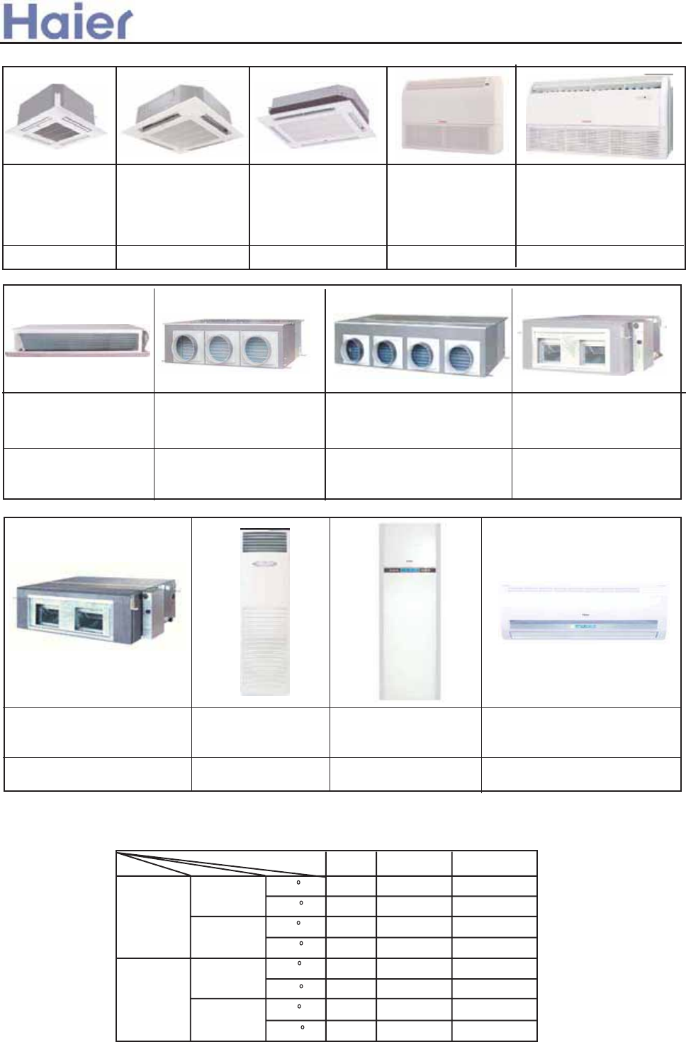
3060405 @\VXR^d UeTd e^Zd
Es=TEGI WEZMRK HIWMKR
AMXL XLI QMRMQYQ XLMGORIWW SJ SRP] wwzQQqXLI YRMX EPQSWX GER FI MRWXEPPIH MRXS ER] HYGXIH WTEGIs3X
RIIHW RSX XLI ZIV] FMK WTEGIqERH [MPP RSX IJJIGX XLI I\XIVMSV HIGSVEXMSRqSRP] PIEZI TISTPI GSQJSVXEFPI
EMV RSX JIIPMRK MXW I\MWXIRGIs
Fs0PI\MFPI LERKMRK OMXW
>LI HYGX YRMXW EVI IUYMTTIH [MXL JPI\MFPI LERKMRK OMXWq[LMGL GER VIEPM^I XLI JVII TSWMXMSR XS MRWXEPP MX MR
ER] HMVIGXMSR*PIJXqVMKLXqYT SV HS[Rs
Gs2MKL IJJMGMIRG] JMPXIV
>LI YRMX EHSTXW 1xKVEHI JMPXIVqGER IJJMGMIRXP] JMPXIV XLI HMVX IXGqERH MQTVSZI XLI VSSQ EMV UYEPMX]qEX XLI
WEQI XMQIqXLI JMPXIV GER TYPP SYX JVSQ HS[RWMHIqGSRZIRMIRX JSV QEMRXIRERGI ERH GPIERMRKs
Hs7YPXMrQSHI JSV MRWXEPPEXMSR
>LI MRHSSV YRMX GER FI MRWXEPPIH [MXL ER EMV VIXYVR HYGX SV [MXLSYX ER EMV VIXYVR HYGX EGGSVHMRK XS XLI MRWXE
rPPEXMSR RIIHs
Is@EVMEFPI GSRXVSP QSHI
>LI MRHSSV YRMX GER FI GSRXVSPPIH F] VIQSXI GSRXVSPPIV SV [MVIH GSRXVSPPIVs+FSYX XLI GSRRIGXMSR QIXLSHq
TPIEWI VIJIV XS FIPS[ JMKYVIW*
Js0VII WIXXMRK SJ EMV HMWGLEVKMRK HYGX
>LI RYQFIV SJ XLI EMVJPS[ SYXPIX ERH MXW MRWXEPPEXMSR TSWMXMSR GER FI JVIIP] WIPIGXIH EGGSVHMRK XS XLI IRZMV
rSRQIRX SJ XLI VSSQqWYJJMGMIRXP] GSRWMHIVMRK XLI PSEH SJ XLI VSSQ ERH XLI YRMJSVQ XIQTIVEXYVI SJ XLI VSSQ
XS VIEPM^I QSVI TIVJIGX GSQJSVXs
Ks2MKL IWT HIWMKR
7E\sI\XIVREP WXEXMG TVIWWYVI SJ v~{ :E FVMRKW XLI UYMGO XIQTIVEXYVI EHNYWXQIRX XS XLI VSSQs+HSTXW LMKL
TVIWWYVI JER XS TVSZMHI UYMGO WTIIH SJ EMV FPS[MRK [LMPI OIITMRK E PS[ WSYRH PIZIP ERH IRWYVMRK E KSSH
EMV GMVGYPEXMSR SJ XLI [LSPI MRHSSV WTEGIs>LI WXEXMG TVIWWYVI JVSQ uXS v~{ :E GER FI EHNYWXIH WXITPIWWP]
EGGSVHMRK XS XLI IRZMVSRQIRXs
Ls?PXVE LMKL LIEH [EXIV HVEMR YT
>LI HYGX YRMXW [MXL GSSPMRK GETEGMX] JVSQ wyuuu_ywuuu,>?tL EHSTX XLI [EXIV TYQT q[LMGL GER FI YT
XS {uuQQs
3060406 CVR\dYi gR\\ ]_e^dVU e^Zdc
Es8I[P] HIWMKRIH @rETTIEVERGI MRHSSV YRMX
>LI [EPP QSYRXIH X]TI MRHSSV YRMX EHSTXW XLI RI[P] HIWMKRIH @ ETTIEVERGIqQSVI JEWLMSRqQSVI
FIEYXMJYPs

Gt9JLFYN[J NTS KZSHYNTS
?MJ ZSNY HFS WJFQN_J YMJ SJLFYN[J NTS LJSJWFYNTS KZSHYNTSrWJQJFXNSL YMJ MJFQYM^ SJLFYN[J NTS NSYT YMJ NSITTW
WTTRtDTZ \NQQ KJJQ RTWJ HTRKTWYFGQJrOZXY QNPJ NS YMJ SFYZWJt
Ht,ZYTsWJXYFWY KZSHYNTS nTUYNTSFQo
,QQ NSITTW ZSNYX MF[J FZYTsWJXYFWY KZSHYNTStBMJS YMJ UT\JW XZUUQ^ HZY TKK XZIIJSQ^rYMJ ZSNY\NQQ FZYTRFYNHFQQ^
WJHT[JW YMJ UWJ[NTZX WZSSNSL RTIJ TSHJ YMJ UT\JW XZUUQ^ NXTSt
It>RFWY SJ\Q^ IJXNLSJI NSKWFWJI WJRTYJ HTSYWTQQJW
?MJ ZSNY HFS GJ HTSYWTQQJI G^ YMJ SJ\Q^ IJXNLSJI NSKWFWJI WJRTYJ HTSYWTQQJW D=s3z*r\MNHM HFS WJFQN_J
RFS^ KZSHYNTSX XZHM FX MJFYNSLrHTTQNSLrKFSrX\NSLrKWJXMrMJFQYMrJYHt1ZWYMJWRTWJrYMJ WJRTYJ HTSYWTQQJW
HFS GJ KN]JI TS YMJ SJHJXXFW^ UQFHJX \NYM F WJRTYJ HTSYWTQQJW MTQIJWt
Jt3JFQYM^ FNW KQT\
y/FNWKQT\rKJJQ RTWJ HTRKTWYFGQJrRTWJ MJFQYM^t
Kt7T\ FRGNJSY HTTQNSL PNYnTUYNTSFQot
Lt8ZQYNUQJ HTSYWTQ Y^UJX nTUYNTSFQot
Ft>YWTSL FNW KQT\ FSI [NXNGQJ TUJWFYNTS INXUQF^ TS YMJ TUJWFYNTS UFSJQ
?MJ ZSNY MF[J XYWTSL H^HQJ FNW KQT\rHFS RJJY YMJ HTTQNSL FSI MJFYNSL WJVZNWJRJSY XTTSrFSI FQXT NY MF[Jt
FIOZXY YMJ YJRUtJ[JSQ^ FSI NRRJINFYJQ^ FSI UWJHNXJQ^ FSI HTRKTWYFGQ^rRJJY YMJ HZXZRJW WJVZJXYRJSYt
Gt8ZQYNUQJ HTSYWTQ Y^UJ GJY\JJS G^ MFSI FSI YMJ WJRTYJ HTSYWTQ
HtAJWYNHFQ FSI MTWN_TSYFQ FNW GQT\ INWJHYNTS HFS GJ FIOZXYJI KWJJQ^ FX \NQQ
It70/ INXUQF^
1TW ,;z~xr |vx,60,,r=ZSSNSL XYFYZX HFS GJ INXUQF^JI TS YMJ XHWJJSt
Jt,ZYTsHMJHP KZSHYNTS
?MJ ZSNY HFS INXUQF^ YMJ RFQKZSHYNTS HTIJX TS YMJ HTSYWTQ GTFWI G^ ZXNSL FI[FSHJI FZYTsHMJHP YJHMSTQTL^r
HTS[JSNJSY KTW ZXJW KNSI FSI I\JQQ \NYM YMJ FGSTWRFQ WZSSNSLt
KtAFWNFGQJ .TSYWTQ RTIJX
2WTZU HTSYWTQ FSI HJSYWFQ HTSYWTQ NK HTSSJHYJI YT F LWTZU HTSYWTQQJW TW F HJSYWFQ HTSYWTQQJWt
3060407 LeWSVj >ST[_We f_[ed
>a__WcU[S^<[c>a`V[e[a`Wc
-8-
>a__WcU[S^<[c>a`V[e[a`Wc
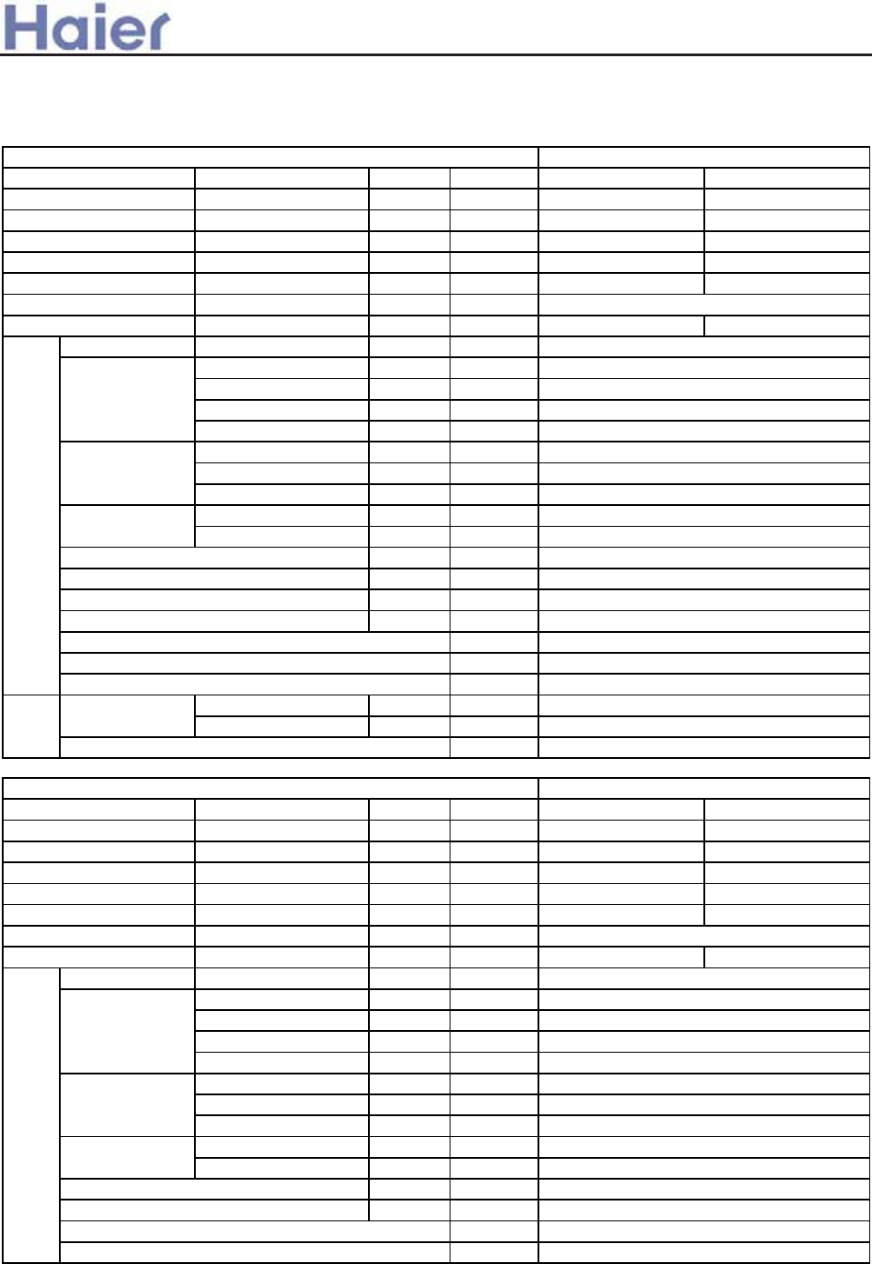
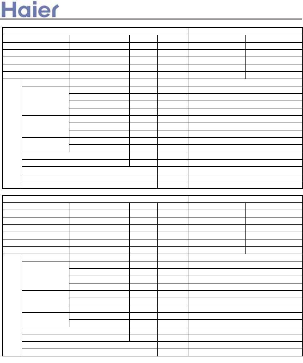
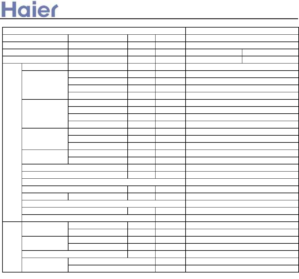
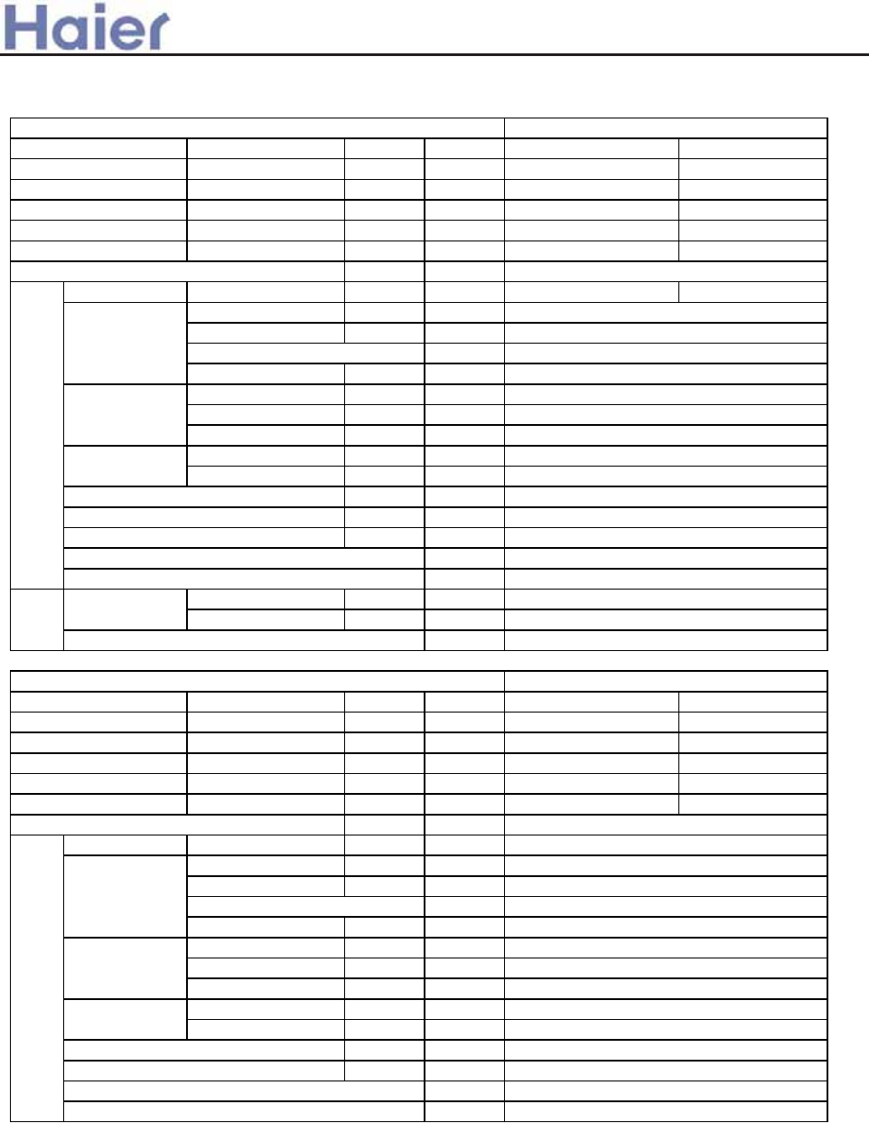
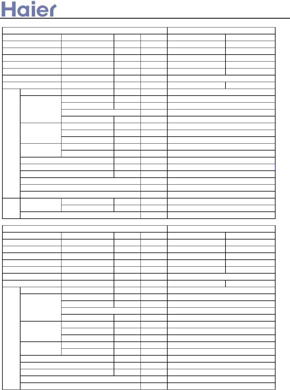
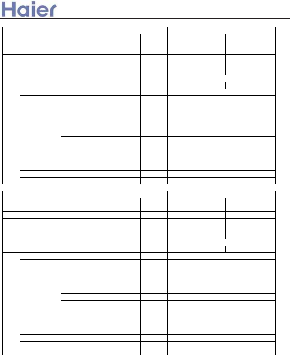
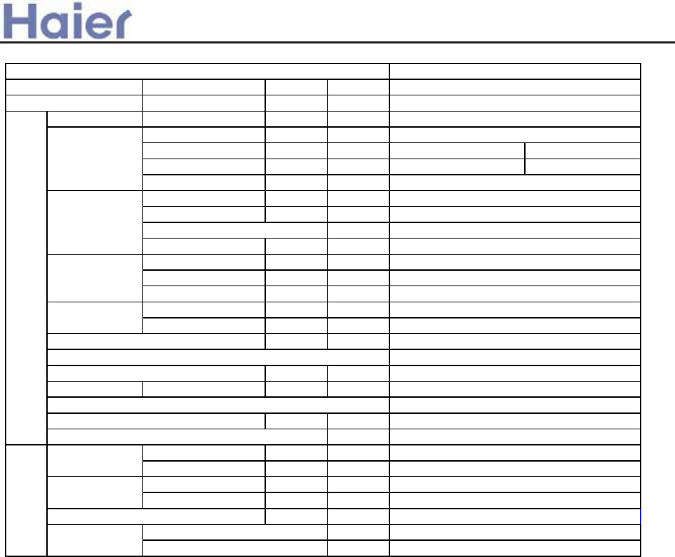
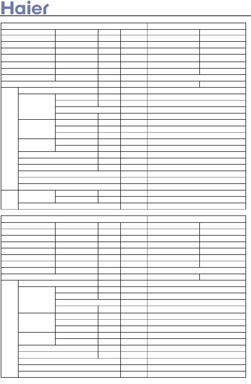
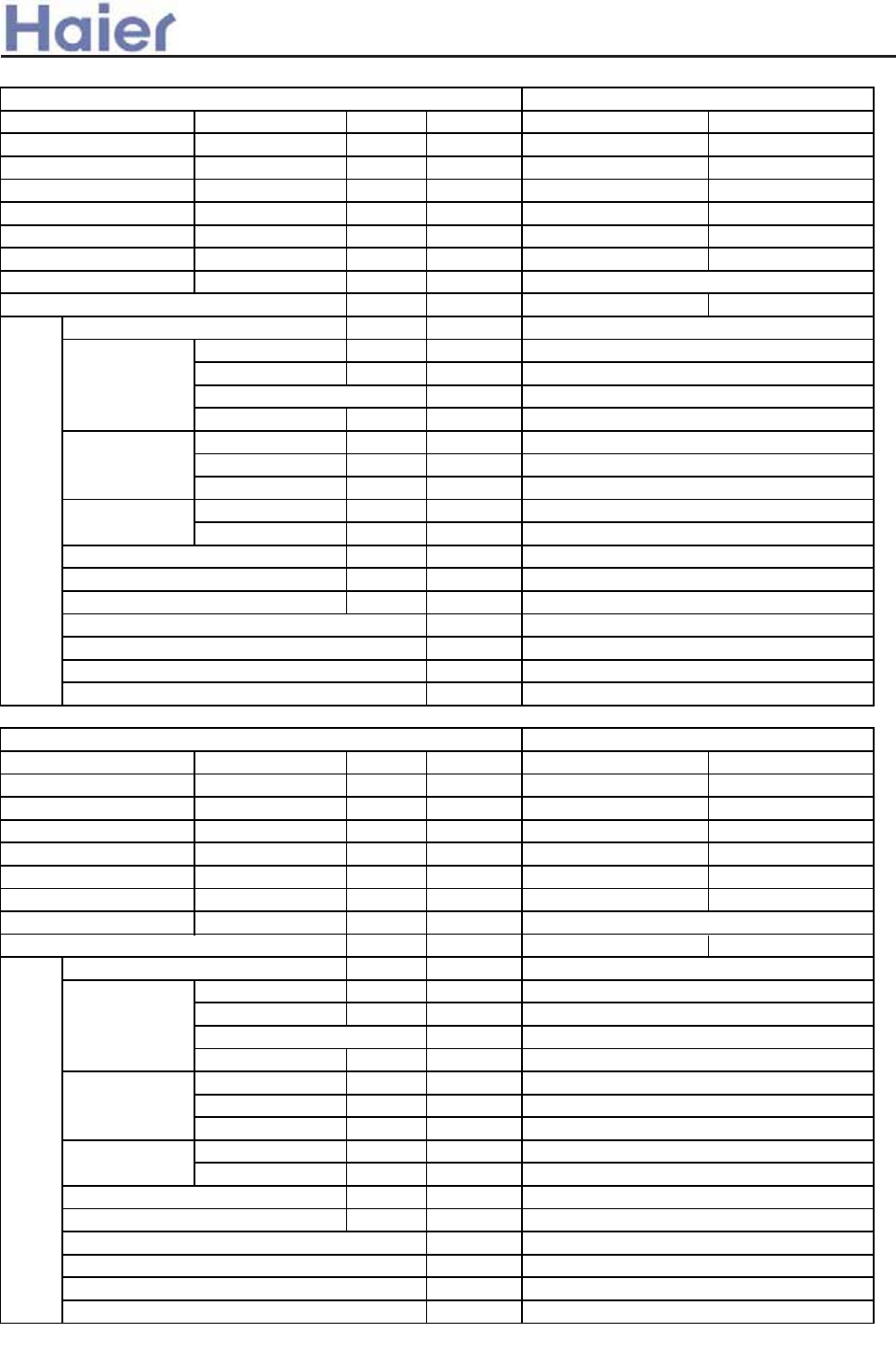
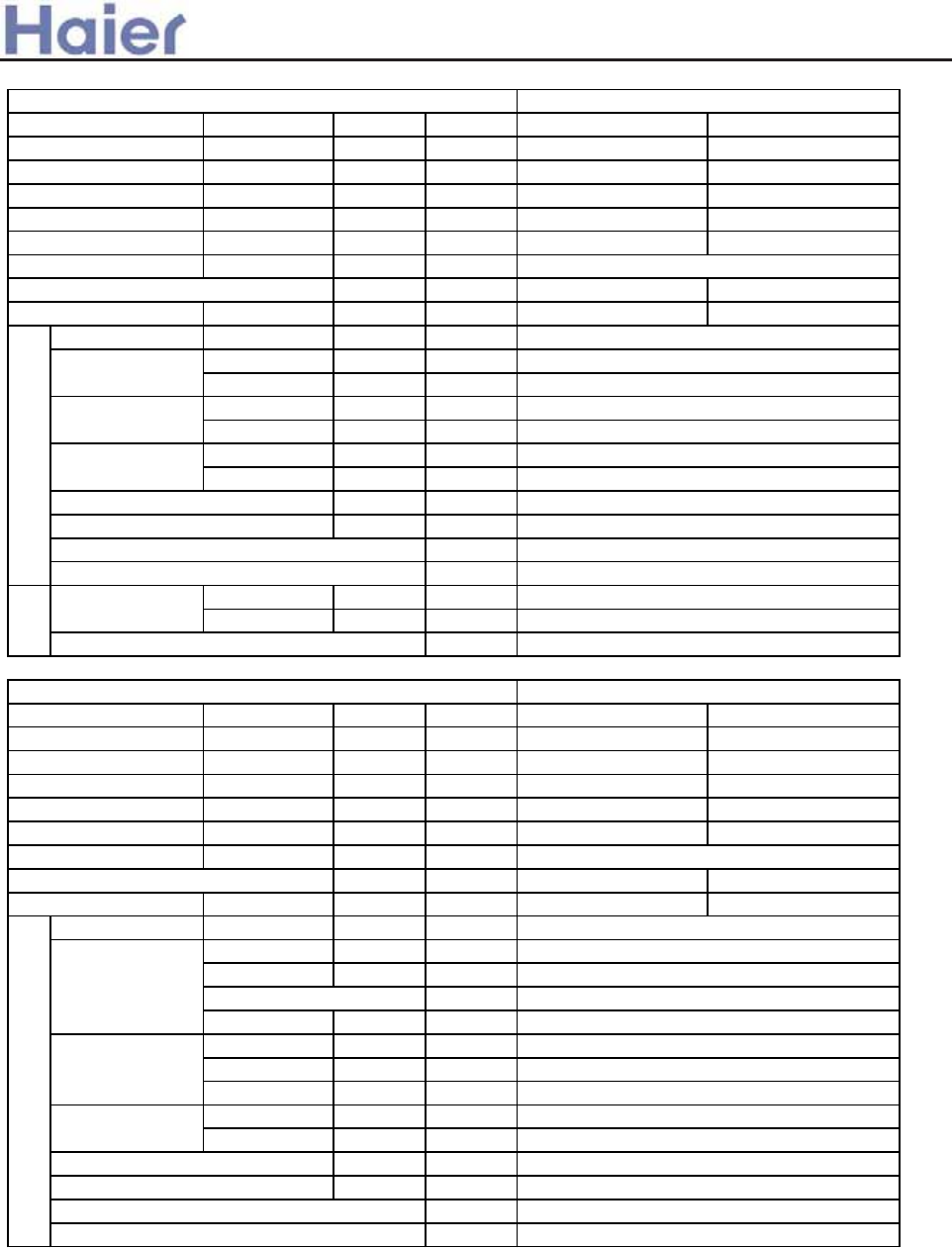
2. Specifications
2.1 Specifications for inverter units
-9-
Function cooling heating
Capacity kW 5.0˄1.8--5.8˅5.2˄2.0---6.2˅
Sensible heat ratio 0.71 /
W1660˄550---2400˅1730˄600---2300˅
W2650 2650
EER or COP W/W 3.01 3.01
Dehumidifying capacity 10ϋ³×m³/h
A / A 7.8(3.0---10.5˅
/
12.0 8.0˄3.2---10˅
/
12.0
Unit model (color)
Type × Number
Speed(H-M-L) r/min
Fan motor output power kW
Air-flow(H-M-L) m³/h
Type / Diameter mm
Total Area m²
Temp. scope ć
External ˄L×W×H˅mm×mm×mm
Package ˄L×W×H˅mm×mm×mm
Drainage pipe (material , I.D./O.D.) mm
Control type (Remote /wired)
Fresh air hole dimension mm
Outlet distribution hole dimension mm
kW
dB(A)
kg / kg
External ˄L×W×H˅mm×mm×mm
Package ˄L×W×H˅mm×mm×mm
kg / kg
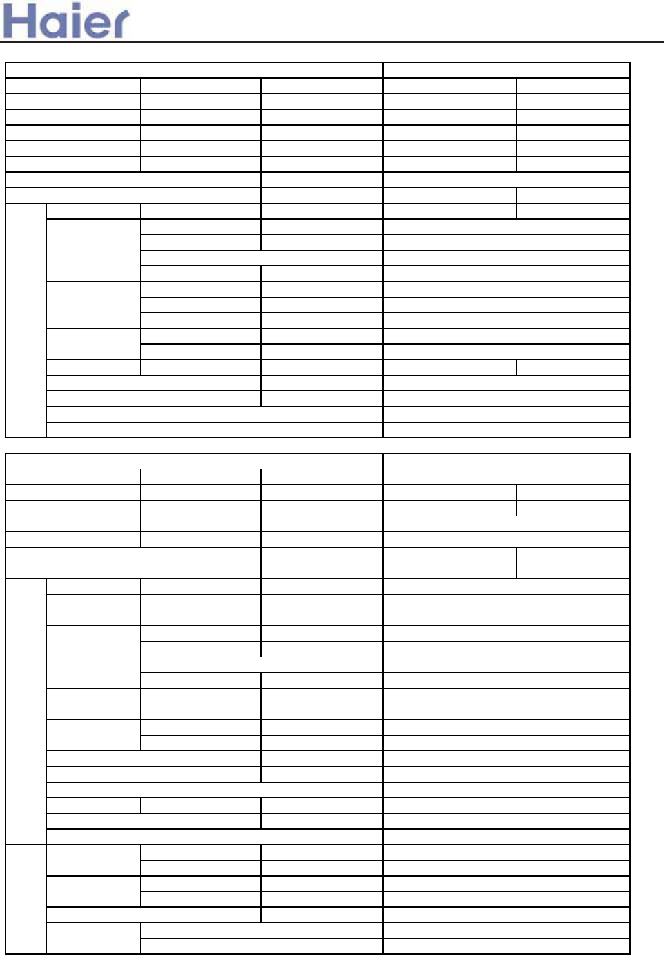
Function cooling heating
Capacity kW 5.1(1.8--5.8) 6.0(2.0---7.1)
Sensible heat ratio 0.71
W 1690(550---2650) 1650(600---2650)
W 2650 2650
EER or COP W/W 3.01 3.63
Dehumidifying capacity 10ϋ³×m³/h
A / A 8.0(3.0--12.0˅A 7.8(3.2--12.0˅A
Unit model (color)
Type × Number
Speed(H-M-L) r/min
Fan motor output power kW
Air-flow(H-M-L) m³/h
Type / Diameter mm
Total Area m²
Temp. scope ć
External ˄L×W×H˅mm×mm×mm
Package ˄L×W×H˅mm×mm×mm
Drainage pipe (material , I.D./O.D.) mm
Control type (Remote /wired)
dB(A)
kg / kg
PVC 18/20
Remote
Noise level (H-M-L) 50/45/40
Weight (Net / Shipping) 30/39
0.45
2-7
Dimension 1090×655×199
1150×750×300
Indoor unit
AC182ACERA(WHITE)
Fan
CENTRIFUGALX2
1150/1050/850
0.05
750/650/550
Heat exchanger
inner grooved pipe/ij7
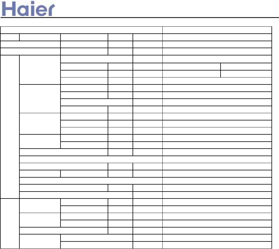
item Model AC182ACERA
Total power input
Max. power input
1.8
Weight (Net / Shipping) 25/27
Panel
Dimension 700×700×60
740×750×115
Weight (Net / Shipping) 3.5/4.5
Indoor unit
AB182ACERA(WHITE)
Electricity Heater 0
Noise level (H-M-L) 44/----
PVC 26/32
Remote
95
/
0.05
700/-----
2-7
Dimension 570×570×260
718×680×380
Heat exchanger
inner grooved pipe/ij7
1.23
Max. power input
Fan
centrifugal*1
760/650/520
2.1
item Model AB182ACERA
Total power input
Running /Max.Running current
Running /Max.Running current
>a__WcU[S^<[c>a`V[e[a`Wc
-10-
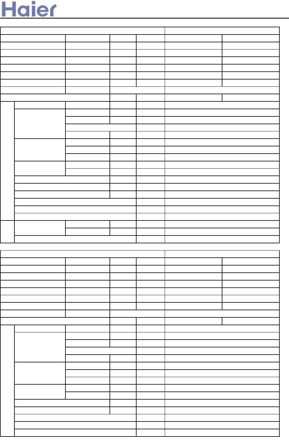
Function cooling heating
Capacity kW 5.1˄1.8---6.0˅6.0˄2.0---7.1˅
Sensible heat ratio 0.75
W1580˄550---2650˅1650˄600---2650˅
W2650 2650
EER or COP W/W 3.23 3.64
Unit model (color)
Type × Number
Speed(H-M-L) r/min
Fan motor output power kW
Air-flow(H-M-L) m³/h
Type / Diameter mm
Total Area m²
Temp. scope ć
External ˄L×W×H˅mm×mm×mm
Package ˄L×W×H˅mm×mm×mm
Drainage pipe (material , I.D./O.D.) mm
Control type (Remote /wired)
kW
dB(A)
kg / kg
Function cooling heating
Capacity kW 5.1˄1.8---6.0˅6.0˄2.0---7.1˅
Sensible heat ratio 0.75
W1580˄550---2650˅1650˄600---2650˅
W2650 2650
EER or COP W/W 3.23 3.64
A / A 7.5˄3.0---12.0˅/12.0 7.8˄3.2---12.0˅/12
Unit model (color)
Type × Number
Speed(H-M-L) r/min
Fan motor output power kW
Air-flow(H-M-L) m³/h
Type / Diameter mm
Total Area m²
Temp. scope ć
External ˄L×W×H˅mm×mm×mm
Package ˄L×W×H˅mm×mm×mm
Drainage pipe (material , I.D./O.D.) mm
Control type (Remote /wired)
dB(A)
kg / kg
Noise level (H-M-L) 44/----
Weight (Net / Shipping) 12/15
Remote
Dimension 870*305*225
962*312*365
PVC 16/12
Heat exchanger
inner grooved pipe/ij7
0.868
2-7
Indoor unit
AS182AVERA(WHITE)
Fan
cross flow*1
1250/1150/1050
0.05
760/-----
Weight (Net / Shipping) 24/27
item Model AS182AVERA
wired
Electricity Heater 0
Noise level (H-M-L) 50/48/45
Dimension 1190*450*220
1281*526*305
PVC 16/12
Heat exchanger
inner grooved pipe/ij9.52
0.59
2-7
Total power input
Indoor unit
AD182AMERA(WHITE)
Fan
cross flow*1
1150/1050/860/680R/MIN
0.05
850/770/680/600(30PA)
item Model AD182AMERA
Total power input
Max. power input
Max. power input
Running /Max.Running current
>a__WcU[S^<[c>a`V[e[a`Wc
-11-
Power cable
Power source N, V, Hz
Start Current A 3A 3A
Circuit breaker A 25A 25A
Unit model (color)
Model / Manufacture
Oil model
Oil charging
Type
Type × Number
Speed r/min
Fan motor output power kW
Air-flow(H-M-L) m³/h
Type / Diameter mm
Row / Fin pitch
Temp. scope ć
External ˄L×W×H˅mm×mm×mm
Package ˄L×W×H˅mm×mm×mm
Drainage pipe (material , I.D./O.D.) mm
Refrigerant control method mm/mm
Volume of Accumulator L
Noise level dB(A)
crankcase heater power W
kg / kg
Type / Charge g
Recharge quantity g/m
Liquid mm
Gas mm
Connecting Method
m
m
Outdoor unit
WHITE
Compressor
TNB175FLBM1/MITSUBISHI ELECTRIC
MEL56
670ML
scroll type
860±30
0.08
2500
item Model AU182AFERA
3G 4.0mm2
1, 220--230, 50
Heat exchanger
hydrophilic finned Aluminum foil /ij7
3/1.55
43-60
Fan
axial×1
Defrosting AUTO
Dimension 810*288*680
960*406*760
2.5
/
main capillary ij1.6*400mm, sub capillary ij
56
Type of Four way valve STF-0218G
30
Weight (Net / Shipping) 59/66
PIPING
Refrigerant R410A/1850
35
Pipe 6.35
12.7
flared
Between I.D &O.D MAX.Drop 15
MAX.Piping length 40
>a__WcU[S^<[c>a`V[e[a`Wc
-12-
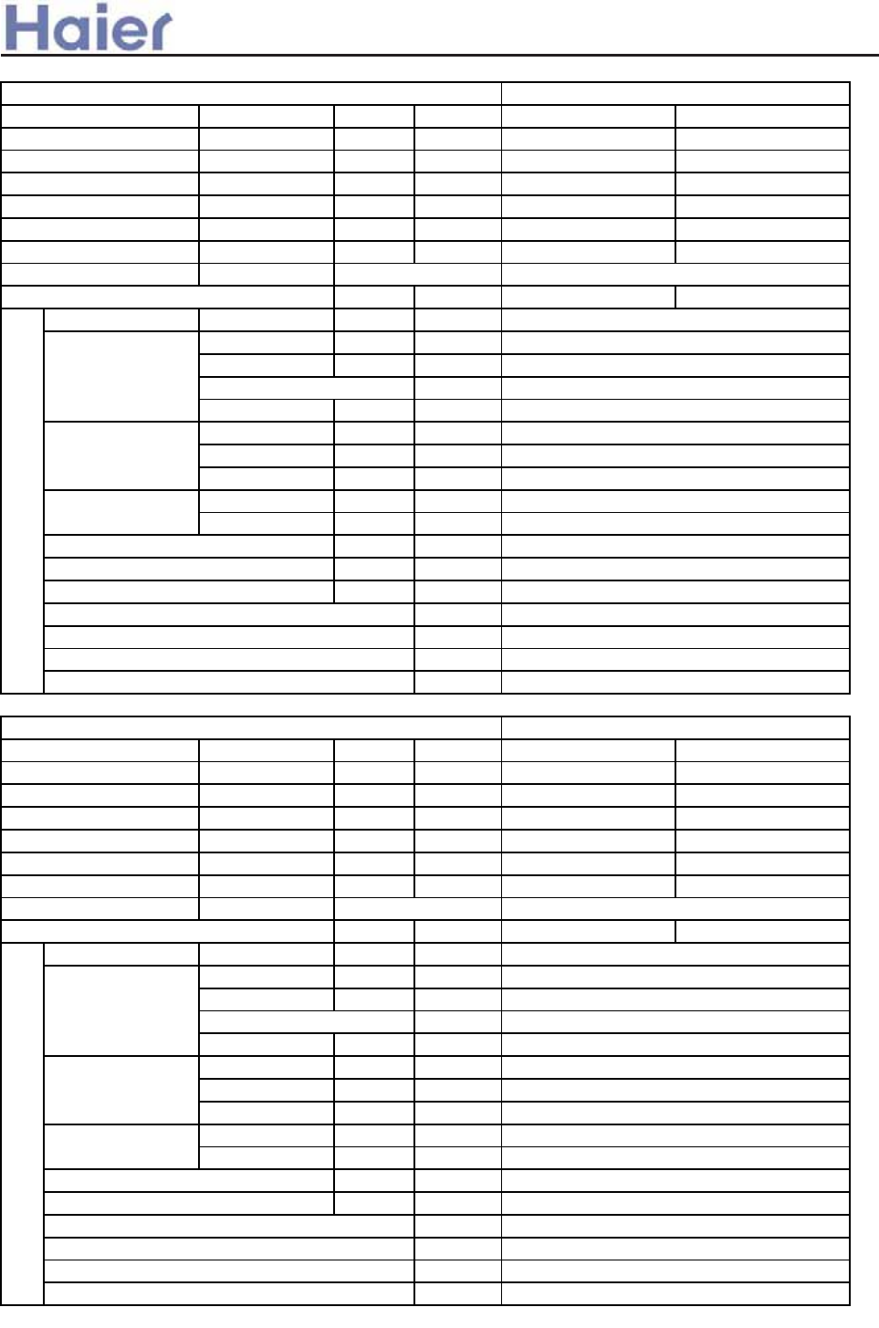
Function cooling heating
Capacity kW 7.0˄2.0---8.0˅7.8˄2.5--8.5˅
Sensible heat ratio 0.72
W 2300(500---3250)W 2.25(500---2750)W
W 3300W 3300W
EER or COP W/W 3.04 3.46
Dehumidifying capacity 10ϋ³×m³/h
A / A 11.0(2.5--14.5˅10.0(2.5--12.0˅
Unit model (color)
Type × Number
Speed(H-M-L) r/min
Fan motor output power kW
Air-flow(H-M-L) m³/h
Type / Diameter mm
Total Area m²
Temp. scope ć
External ˄L×W×H˅mm×mm×mm
Package ˄L×W×H˅mm×mm×mm
Drainage pipe (material , I.D./O.D.) mm
Control type (Remote /wired)
Fresh air hole dimension mm
dB(A)
kg / kg
External ˄L×W×H˅mm×mm×mm
Package ˄L×W×H˅mm×mm×mm
kg / kg
Function cooling heating
Capacity kW 6.5(2.0-8.0) 7.5(2.5-8.5)
Sensible heat ratio 0.72
W2240W(500-3250) 2550(500-3250)
W3300W 3300W
EER or COP W/W 2.90˄C˅2.94˄E˅
Dehumidifying capacity 10ϋ³×m³/h
A / A 10(2.5-14.5)A/15A 11.5(2.5-14.5)A/15A
Unit model (color)
Type × Number
Speed(H-M-L) r/min
Fan motor output power kW
Air-flow(H-M-L) m³/h
Type / Diameter mm
Total Area m²
Temp. scope ć
External ˄L×W×H˅mm×mm×mm
Package ˄L×W×H˅mm×mm×mm
Drainage pipe (material , I.D./O.D.) mm
Control type (Remote /wired)
dB(A)
kg / kg
PVC 18/20
Remote or wired
Noise level (H-M-L) 48/46/44
Weight (Net / Shipping) 28.3/34.3
0.49
2-7
Dimension 990*665*199
1150*750*300
Indoor unit
AC242ACERA(WHITE)
Fan
Centrifugal h 2
1220±40/1190±50/1050±50/980±50r/min
0.10
800/-/-
Heat exchanger
Inner grooved type /¶7
980*980*100
Weight (Net / Shipping) /
Noise level (H-M-L) 48/44/39
Total power input
Max. power input
item Model AC242ACERA
Weight (Net / Shipping) 26.8/32.6
Panel
Dimension
Dimension 840*840*240
910*910*300
PVC 26/32
Indoor unit
AB242ACERA(black)
Fan
Centrifugal × 1
670±40/550±50/460±50
0.16
1300/-/-
Heat exchanger
Inner grooved type /¶7
1.8
0.49
2-7
Remote or wired
130
2.0
950*950*80
item Model AB242ACERA
Total power input
Max. power input
Running /Max.Running current
Running /Max.Running current
>a__WcU[S^<[c>a`V[e[a`Wc
-13-
Function cooling heating
Capacity kW 7.35˄2.0---8.2˅8.15˄3.0---9.0˅
Sensible heat ratio 0.72 /
W2280(600---3250)W 2250(600---3250)W
W3300W 3300W
EER or COP W/W
A / A 10.0(2.5--14.5)A /
15.0A
10.0(2.5--14.5)A /
15.0A
Unit model (color)
Type × Number
Speed(H-M-L) r/min
Fan motor output power kW
Air-flow(H-M-L) m³/h
Type / Diameter mm
Total Area m²
Temp. scope ć
External ˄L×W×H˅mm×mm×mm
Package ˄L×W×H˅mm×mm×mm
Drainage pipe (material , I.D./O.D.) mm
Control type (Remote /wired)
dB(A)
kg / kg
Function cooling heating
Capacity kW 7.35˄2.0---8.2˅8.15˄2.5-9.0˅
Sensible heat ratio 0.72
W2280(600---3250)W 2250(600---3250)W
W3300W 3300W
EER or COP W/W 3.22 3.62
Dehumidifying capacity 10ϋ³×m³/h
A / A 10.5(2.5--14.5)A / 15A 10.0(2.5--14.5)A /1 5A
Unit model (color)
Type × Number
Speed(H-M-L) r/min
Fan motor output power kW
Air-flow(H-M-L) m³/h
Type / Diameter mm
Total Area m²
Temp. scope ć
External ˄L×W×H˅mm×mm×mm
Package ˄L×W×H˅mm×mm×mm
Drainage pipe (material , I.D./O.D.) mm
Control type (Remote /wired)
Fresh air hole dimension mm
dB(A)
kg / kg
Noise level (H-M-L) 47/43/39
Weight (Net / Shipping) 39/40.4
PVC 32/26
Remote or wired
150
2-7
Dimension 990*650*300
1170*860*340
item Model AD242AMERA
Total power input
Max. power input
Indoor unit
AD242AMERA(grey)
Fan
Centrifugal h 2
1000±40/940±40/860±40/780±50
0.18
1200/1050/850
Heat exchanger
Inner grooved type /¶7
0.49
PVC 16/12
Remote or wired
2.1
Noise level (H-M-L) 49/45/41/37
Weight (Net / Shipping) 25.2/28.4
2-7
Dimension 1090*500*220
1174*549*294
item Model AD242ALERA
Total power input
Max. power input
Indoor unit
AD242ALERA(grey)
Fan
Centrifugal h 2
1250±40/1130±40/1000±50/850±50
0.05
1200/1050/850˄white port, 0Pa static
Heat exchanger
Inner grooved type /¶7
0.51
Running /Max.Running
current
2.0
Running /Max.Running current
>a__WcU[S^<[c>a`V[e[a`Wc
-14-
Power cable
Power source N, V, Hz
Start Current A 33
Unit model (color)
Model / Manufacture
Oil model MEL56
Oil charging 670ML
Type
Type × Number
Speed r/min
Fan motor output power kW
Air-flow(H-M-L) m³/h
Type / Diameter mm
Row / Fin pitch
Temp. scope ć
External ˄L×W×H˅mm×mm×mm
Package ˄L×W×H˅mm×mm×mm
Drainage pipe (material , I.D./O.D.) mm
Refrigerant control method mm/mm
Volume of Accumulator L
Noise level dB(A)
crankcase heater power W
kg / kg
Type / Charge g
Recharge quantity g/m
Liquid mm
Gas mm
Connecting Method
m
m
Outdoor unit
WHITE
Compressor
TNB175FLBM1˄MITSUBISHI˅
Rotary
Fan
axial×1
910±30
0.06
3000
Heat exchanger
¶7
3/1.46
43-60
Dimension 865*335*732
995*420*815
/
Type of Four way valve SHF-4-10A
37
2.4mm EEV
Defrosting AUTO
3
Weight (Net / Shipping) 57/60.5
PIPING
Refrigerant R410A/2300
50
Pipe 9.52
15.88
Flare cnnection
Between I.D &O.D MAX.Drop 15
MAX.Piping length 30
item Model AU242AGERA
56
1PH,220-230VAC,50HZ
3G 4.0mm2
>a__WcU[S^<[c>a`V[e[a`Wc
-15-
Function coolin
g
heatin
g
Ca
p
acit
y
Btu/h 33800 38200
Capacity kW 9.9(2.2~11.6) 11.2(2.5~12.0)
Sensible heat ratio 0.73
W 3290(650---3800) 3280(650---3800)
W4300 4300
EER or COP W/W 3.01 3.09
Energy efficiency stage B D
Dehumidifying capacity 10ϋ³×m³/h
A / A 14.3(2.9-17.0)/19.3 14.3(2.9-17.0)/19.3
Unit model (color)
Type × Number
Speed(H-M-L) r/min
Air-flow(H-M-L) m³/h
Type / Diameter mm
Total Area m²
Temp. scope ć
External ˄L×W×H˅
mm×mm×mm
Package ˄L×W×H˅
mm×mm×mm
Drainage pipe (material , I.D./O.D.) mm
Control type (Remote /wired)
dB(A)
kg / kg
External ˄L×W×H˅
mm×mm×mm
Package ˄L×W×H˅
mm×mm×mm
kg / kg
Function cooling heating
Capacity Btu/h 35000 39000
Capacity kW 10.3(2.2~11.5) 11.4(2.5~12.0)
Sensible heat ratio 0.73
W 3200(500---3900) 3250(500---3900)
W4300 4300
EER or COP W/W 3.22 3.51
Energy efficiency stage A B
Dehumidifying capacity 10ϋ³×m³/h
A / A 14.3(2.3-17.5)/19.3 14.3(2.3-17.5)/19.3
Unit model (color)
Type × Number
Speed(H-M-L) r/min
Air-flow(H-M-L) m³/h
Type / Diameter mm
Total Area m²
Temp. scope ć
External ˄L×W×H˅
mm×mm×mm
Package ˄L×W×H˅
mm×mm×mm
Drainage pipe (material , I.D./O.D.) mm
Control type (Remote /wired)
dB(A)
kg / kg
1850/1600/1350
Heat exchanger
item Model AB362ACERA
Total power input
Max. power input
Dimension 1230/840/280
1325/920/370
3.8
Indoor unit
AB362ACERA˄BLACK)
Fan
Centrifugal fan * 1
620/450/390±40
PVC 26/32
remote/wired
inner grooved type/¶7
2-7
Weight (Net / Shipping) 46/53
Noise level (H-M-L) 50/46/42
Panel
Dimension 1340/950/80
1400/995/115
Weight (Net / Shipping) 8.4/12
item Model AC362AFERA
Total power input
Max. power input
4.0
Running /Max.Running current
1800/1600/1400
Heat exchanger
inner grooved type/¶7
0.340
PP20/25
remote/wired
2-7
Dimension 1580/700/240
1710/790/315
Noise level (H-M-L) 51/49/47
Weight (Net / Shipping) 54/61
Indoor unit
AC362AFERA˄WHITE)
Fan
Centrifugal fan * 4
1150/1100/950
0.583
Running /Max.Running current
Function cooling heating
Capacity BTU/h 36000 39000
Capacity kW 10.5(2.2~11.3) 11.5(2.5~12.5)
Sensible heat ratio 0.73
W 3.40(0.50---4.00) 3.15(0.50---4.00)
W4300 4300
EER or COP W/W 3.09 3.65
Energy efficiency stage BA
Dehumidifying capacity 10ϋ³×m³/h
A / A 15.2˄2.3-17.9˅/19.3 14.1˄2.3-17.9˅/19.3
Unit model (color)
Type × Number
Speed(H-M-L) r/min
Fan motor output power kW
Air-flow(H-M-L) m³/h
Type / Diameter mm
Temp. scope ć
External ˄L×W×H˅mm×mm×mm
Package ˄L×W×H˅mm×mm×mm
Drainage pipe (material , I.D./O.D.) mm
Control type (Remote /wired)
dB(A)
kg / kg
Weight (Net / Shipping) 62/77
Noise level (H-M-L) 48/-/44
PVC 26/32
wired
2-7
Dimension 1197×828×355
1430×940×420
Indoor unit
AD362AHERA (grey)
Fan
centrifugal X2
1090+30/-/930+50
0.15
2580/-/1560
Heat exchanger TP2M/9.52
Total power input
Max. power input
4.1
item Model AD362AHERA
>a__WcU[S^<[c>a`V[e[a`Wc
-16-
Running /Max.Running current
Function cooling heating
Capacity BTU/h 32400 38000
Capacity kW 9.5(2.2~10.8) 11.0(2.5~12.0)
Sensible heat ratio 0.73
W 3280(500---3900) 3430(500---3900)
W4300 4300
EER or COP W/W 2.9 3.21
Energy efficiency stage CC
Dehumidifying capacity 10ϋ³×m³/h
A / A 14.3(2.3-17.5)/19.3 15.0(2.3-17.5)/19.3
Unit model (color)
Type × Number
Speed(H-M-L) r/min
Air-flow(H-M-L) m³/h
Type / Diameter mm
Total Area m²
Temp. scope ć
External ˄L×W×H˅
mm×mm×mm
Package ˄L×W×H˅
mm×mm×mm
Drainage pipe (material , I.D./O.D.) mm
Control type (Remote /wired)
Fresh air hole dimension mm
dB(A)
kg / kg
item Model AD362AMERA
Heat exchanger
inner grooved type/¶7
0.328
Total power input
Max. power input
3.6
Dimension 990*650*300
1152*860*325
Indoor unit
AD362AMERA(grey)
Fan
Centrifugal fan * 2
1110±50/ 1060±40 / 950±40 / 790±50r/min
1470/1300/1100/950
wired
150
2-7
Noise level (H-M-L) 50/47/43/41
Weight (Net / Shipping)
PVC 26/32
40/46.4
Running /Max.Running current
>a__WcU[S^<[c>a`V[e[a`Wc
-17-
Power cable
Power source N, V, Hz
Start Current A
Unit model (color)
Model / Manufacture
Type
Type × Number
Speed r/min
Fan motor output power kW
Air-flow(H-M-L) m³/h
Type / Diameter mm
Total area m²
Temp. scope ć
External ˄L×W×H
˅
mm×mm×mm
Package ˄L×W×H
˅
mm×mm×mm
Refrigerant control method mm/mm
Volume of Accumulator L
Noise level dB(A)
crankcase heater power W
kg / kg
Type / Charge g
Recharge quantity g/m
Liquid mm
Gas mm
Connecting Method
m
m
Norminal condition: indoor temperature (cooling): 27ćDB/19ćWB, indoor temperature (heating): 20ć
DB/14.5ćWB
Outdoor temperature(cooling): 35ćDB/24ćWB, outdoor temperature(heating): 7ćDB/6ćWB
The noise level will be measured in the third octave band limited values, using a Real Time Analyser
calibrated sound intensity meter. It is a sound pressure noise level.
flared
Item Model AU362AHERA
3*4.0
1, 220-230, 50
3
Outdoor unit
AU362AHERA˄WHITE˅
Compressor Rotary
Fan
axial*1
Dimension 948*340*830
1050*440*979
950r/min±50
0.06
4000/-/-
Heat exchanger
TP2M/7
0.776
43-60
60
electrical expansion valve 2.2mm
Defrosting auto
3.5
37
Weight(Net / Shipping) 74/80
PIPING
Refrigerant R410A 2650
65
Pipe 9.52
15.88
Between I.D &O.D MAX.Drop 30
MAX.Piping length 50
TNB220FLBM/MITSUBISHI
-
>a__WcU[S^<[c>a`V[e[a`Wc
2.2 Specifications for fix frequency unit
-18-
Function cooling heating
Capacity BTU/h 17000 18000
Capacity kW 5.0 5.3
W1780 1550
W2050 1950
EER or COP W/W 2.81 3.41
A / A
Unit model (color) AB182ACEAA Grey
Type × Number
Speed(H-M-L) r/min
Fan motor output power kW
Air-flow(H-M-L) m³/h
Type / Diameter mm
Total Area m²
Temp. scope ć
External ˄L×W×H˅mm×mm×mm
Package ˄L×W×H˅mm×mm×mm
Drainage pipe (material , I.D./O.D.) mm
Control type (Remote /wired /model)
Fresh air hole dimension mm
dB(A)
kg / kg
External ˄L×W×H˅mm×mm×mm
Package ˄L×W×H˅mm×mm×mm
kg / kg
Function cooling heating
Capacity BTU/h 17500 18600
Capacity kW 5.1 5.45
W1690 1650
W2000 1950
EER or COP W/W 3.02 3.3
A / A
Unit model (color)
Type × Number
Speed(H-M-L) r/min
Fan motor output power kW
Air-flow(H-M-L) m³/h
Type / Diameter mm
Total Area m²
Temp. scope ć
External ˄L×W×H˅mm×mm×mm
Package ˄L×W×H˅mm×mm×mm
Drainage pipe (material , I.D./O.D.) mm
Control type (Remote /wired /model)
dB(A)
kg / kg
WHITE
Running /Max.Running current
item Model AC182ACEAA
Total power input
Max. power input
Noise level (H-M-L) 48/46/44
TP2M/7X0.5
0.49
2-7
Dimension 990x665x199
1150x750x300
Heat exchanger
Panel
Dimension
Weight (Net / Shipping)
PVC 18/20
cooling: 7.6A /10.5A heating: 7.5A /10.0A
Running /Max.Running current
Indoor unit
Fan
centrifugal fan X 2
item Model
Total power input
Max. power input
Indoor unit
Fan
Heat exchanger
Dimension
AB182ACEAA
cooling: 7.5A /10.5A heating: 7.0A /10.0A
Noise level (H-M-L)
Weight (Net / Shipping) 19/23.5
axial fan X 1
750±20 / 650±30/ 520±30
remote / 0010451255
ɮ100
45/42/40
Weight (Net / Shipping) 28.3/34.3
700×700×60
PVC 14/16
740×740×115
3.5/4.5
Remote /wired
1190±50 / 1050±50/980±50
100
800
50
700/640/480
TP2M/7X0.5
0.441
2-7
570x570x260
718x680x380
>a__WcU[S^<[c>a`V[e[a`Wc
-19-
Function cooling heating
Capacity BTU/h 18000 18500
Capacity kW 5.17 5.38
W1720 1580
W2000 1950
EER or COP W/W 3.01 3.41
A / A
Class of anti electric shock Class 1
Unit model (color) AD182ALEAA Grey
Type × Number
Speed(H-M-L) r/min
Fan motor output power kW
Air-flow(H-M-L) m³/h
Type / Diameter mm
Total Area m²
Temp. scope ć
External ˄L×W×H˅mm×mm×mm
Package ˄L×W×H˅mm×mm×mm
Air sending angle
Drainage pipe (material , I.D./O.D.) mm
Control type (Remote /wired /model)
dB(A)
kg / kg
Dehumidifying capacity 10ϋ³×m³/h
Signal cable section 3 2.5
Connecting cable section 4 0.75
Power source N, V, Hz
Start Current A
Max. operating pressure of heat side Mpa 4.5
Max. operating pressure of cold side Mpa 4.5
Unit model (color)
Model / Manufacture
Type
Type × Number
Speed r/min
Fan motor output power kW
Air-flow(H-M-L) m³/h
Type / Diameter mm
Temp. scope ć
External ˄L×W×H˅mm×mm×mm
Package ˄L×W×H˅mm×mm×mm
Drainage pipe (material , I.D./O.D.) mm
Refrigerant control method mm/mm
Noise level dB(A)
material of reduce noise
kg / kg
Type / Charge g
Recharge quantity g/m
Liquid mm
Gas mm
Connecting Method
m
m
item Model AU182AEEAA
PIPING
Refrigerant R410A/1500
20
Pipe 6.35
12.7
flared
Between I.D &O.D MAX.Drop 10
MAX.Piping length 20
56
XPE
Weight (Net / Shipping) 42/45
/
Capillary tube
Defrosting controlled by coil temp.
TP2M/7X0.5
43-60
Dimension 775x640x245
901x341x712
Rotary
Fan
Axial X 1
860±40
35
2300
Running /Max.Running current cooling: 7.8A /9.5A heating 7.3A /9.3A
50
2-7
item Model AD182ALEAA
Total power input
Max. power input
1.8
1 PH 220-230 V 50 Hz
Outdoor unit
Compressor
Heat exchanger
AU182AEEAA (WHITE)
Indoor unit
Fan
centrifugal fan X 2
700±30 / 540±30 / 400±30
50
780
Heat exchanger
TP2M/7X0.5
0.34
Dimension 1090×500×220
1174×549×294
Noise level (H-M-L) 45/41/37
PVC 16/12
wired control
PA200X2CS-4KU1/Meizhi
Weight (Net / Shipping) 23/26.5
>a__WcU[S^<[c>a`V[e[a`Wc
-20-
Function cooling heating
Capacity kW 7.25 7.4
Sensible heat ratio 0.72 /
W 2400 2300
W 3100W 3000W
EER or COP W/W 3.02 3.22
Dehumidifying capacity 10ϋ³×m³/h
A / A 11.0A/13.9A 10.5A/13.4A
Unit model (color)
Type × Number
Speed(H-M-L) r/min
Fan motor output power kW
Air-flow(H-M-L) m³/h
Type / Diameter mm
Total Area m²
Temp. scope ć
External ˄L×W×H˅mm×mm×mm
Package ˄L×W×H˅mm×mm×mm
Drainage pipe (material , I.D./O.D.) mm
Control type (Remote /wired)
Fresh air hole dimension mm
kW
dB(A)
kg / kg
External ˄L×W×H˅mm×mm×mm
Package ˄L×W×H˅mm×mm×mm
kg / kg
Function cooling heating
Capacity kW 6.8 7.4
Sensible heat ratio 0.72 /
W2400 2450
W3100W 3000W
EER or COP W/W 2.83 3.02
Dehumidifying capacity 10ϋ³×m³/h
A / A 10.5A/13.9A 11.2A/13.4A
Unit model (color)
Type × Number
Speed(H-M-L) r/min
Fan motor output power kW
Air-flow(H-M-L) m³/h
Type / Diameter mm
Total Area m²
Temp. scope ć
External ˄L×W×H˅mm×mm×mm
Package ˄L×W×H˅mm×mm×mm
Drainage pipe (material , I.D./O.D.) mm
Control type (Remote /wired)
Fresh air hole dimension mm
dB(A)
kg / kg
Noise level (H-M-L) 48/46/44
Weight (Net / Shipping) 28.3/34.3
PVC 18/20
Remote /wired (optional)
/
2-7
Dimension 990*665*199
1150*750*300
Indoor unit
WHITE
Fan
centrifugal fan*2
1220±40/1190±50/1050±50/980±50r/min
0.10
800/-/-
Heat exchanger
inner grooved pipe/ij7
0.49
AC242ACEAA
Total power input
Max. power input
2.5
Panel
Dimension 950*950*80
980*980*100
Weight (Net / Shipping) /
Remote /wired (optional)
130
Electricity Heater 0
Noise level (H-M-L) 48/44/39
Weight (Net / Shipping) 26.8/32.6
item Model
Dimension 840*840*240
910*910*300
PVC 26/32
Heat exchanger
inner grooved pipe/ij7
0.49
2-7
centrifugal fan*1
670±40/550±50/460±50
0.16
1300/-/-
2.5
Indoor unit
grey
Fan
item Model AB242ACEAA
Total power input
Max. power input
Running /Max.Running current
Running /Max.Running current
>a__WcU[S^<[c>a`V[e[a`Wc
-21-
Function cooling heating
Capacity kW 7.25 7.6
Sensible heat ratio 0.72 /
W2400 2300
W3100W 3000W
EER or COP W/W 3.02 3.30
Dehumidifying capacity 10ϋ³×m³/h
A / A 11.0A/13.9A 10.5A/13.4A
Unit model (color)
Type × Number
Speed(H-M-L) r/min
Fan motor output power kW
Air-flow(H-M-L) m³/h
Type / Diameter mm
Total Area m²
Temp. scope ć
External ˄L×W×H˅mm×mm×mm
Package ˄L×W×H˅mm×mm×mm
Drainage pipe (material , I.D./O.D.) mm
Control type (Remote /wired)
dB(A)
kg / kg
Function cooling heating
Capacity kW 7.25 7.6
Sensible heat ratio 0.72 /
W2400 2300
W3100W 3000W
EER or COP W/W 3.02 3.30
Dehumidifying capacity 10ϋ³×m³/h
A / A 11.0A/13.9A 10.5A/13.4A
Unit model (color)
Type × Number
Speed(H-M-L) r/min
Fan motor output power kW
Air-flow(H-M-L) m³/h
Type / Diameter mm
Total Area m²
Temp. scope ć
External ˄L×W×H˅mm×mm×mm
Package ˄L×W×H˅mm×mm×mm
Drainage pipe (material , I.D./O.D.) mm
Control type (Remote /wired)
Fresh air hole dimension mm
dB(A)
kg / kg
Weight (Net / Shipping) 39/40.4
PVC 32/26
wired control
150
Noise level (H-M-L) 47/43/39
inner grooved pipe/ij7
0.49
2-7
Dimension 990*650*300
1170*860*340
Indoor unit
grey
Fan
centrifugal fan*2
1000±40/940±40/860±40/780±50
0.18
1200/1050/850
Heat exchanger
item Model AD242AMEAA
Noise level (H-M-L) 49/45/41/37
Weight (Net / Shipping) 25.2/28.4
Dimension 1090*500*220
1174*549*294
PVC 16/12
Indoor unit
grey
Fan
centrifugal fan*2
1250±40/1130±40/1000±50/850±50
0.05
1200/1050/850 (white port: 0Pa)
Heat exchanger
inner grooved pipe/ij7
Total power input
Max. power input
item Model AD242ALEAA
Total power input
Max. power input
2.5
1.8
0.51
2-7
wired control
Running /Max.Running current
Running /Max.Running current
>a__WcU[S^<[c>a`V[e[a`Wc
-22-
Power cable
Power source N, V, Hz
Unit model (color)
Model / Manufacture
Oil model VG74
Oil charging 950ML
Type
Type × Number
Speed r/min
Fan motor output power kW
Air-flow(H-M-L) m³/h
Type / Diameter mm
Row / Fin pitch
Temp. scope ć
External ˄L×W×H˅mm×mm×mm
Package ˄L×W×H˅mm×mm×mm
Refrigerant control method mm/mm
Volume of Accumulator L
Noise level dB(A)
crankcase heater power W
kg / kg
Type / Charge g
Recharge quantity g/m
Liquid mm
Gas mm
Connecting Method
m
m
PIPING
Refrigerant R410A/2100
50
Pipe 9.52
15.88
flare
Between I.D &O.D MAX.Drop 15
MAX.Piping length 30
Weight (Net / Shipping) 57/60.5
3
57
Type of Four way valve SHF-4-10A
3000
37
ĭ1.8*300 capillary
item Model AU242AGEAA
Outdoor unit
WHITE
Compressor
PA290X3CS-4MU1˄TOSHIBA˅
Rotary
Fan
axial×1
1000±50
Defrosting AUTO
Heat exchanger
TP2M/ij7
3/1.46
43-60
0.06
1PH,220-230VAC,50HZ
H05RN-F 3G 4.0mm2
Dimension 865*335*732
995*420*815
>a__WcU[S^<[c>a`V[e[a`Wc
6
Function coolin
g
heatin
g
Capacity BTU/h 28000 30000
Capacity kW 8.2 8.8
Sensible heat ratio 0.72 /
W 2700 2740
W 3400W 3500W
EER or COP W/W 3.04 3.21
Dehumidifying capacity 10ϋ³×m³/h
A / A 12.0A/15.0A 12.2A/15.5A
Unit model (color)
Type × Number
Speed(H-M-L) r/min
Fan motor output power kW
Air-flow(H-M-L) m³/h
Type / Diameter mm
Total Area m²
Temp. scope ć
External ˄L×W×H˅
mm×mm×mm
Package ˄L×W×H˅
mm×mm×mm
Drainage pipe (material , I.D./O.D.) mm
Control type (Remote /wired)
Fresh air hole dimension mm
kW
dB(A)
kg / kg
External ˄L×W×H˅
mm×mm×mm
Package ˄L×W×H˅
mm×mm×mm
kg / kg
Function cooling heating
C
apacity BTU/h 28000 32500
Capacity kW 8.6 9.5
Sensible heat ratio 0.72 /
W2680 2630
W3400W 3500W
EER or COP W/W 3.21 3.61
Dehumidifying capacity 10ϋ³×m³/h
A / A 12.0A/15.0A 11.7A/15.0A
Unit model (color)
Type × Number
Speed(H-M-L) r/min
Fan motor output power kW
Air-flow(H-M-L) m³/h
Type / Diameter mm
Total Area m²
Temp. scope ć
External ˄L×W×H˅
mm×mm×mm
Package ˄L×W×H˅
mm×mm×mm
Drainage pipe (material , I.D./O.D.) mm
Control type (Remote /wired)
kW
dB(A)
kg / kg
Running /Max.Running current
Running /Max.Running current
item Model
Total power input
Max. power input
1550/1300/1000
Indoor unit
AB282ACEAA(grey)
Fan
Centrifugal fan * 1
670±40/600±50/460±50
0.16
1300/1100/870
Heat exchanger
inner grooved type/¶7
0.49
2-7
Dimension 840*840*240
910*910*300
PVC 26/32
remote/wired (optional)
130
0.10
Electricity Heater 0
Noise level (H-M-L) 48/44/39
Weight (Net / Shipping) 26.8/32.6
Panel
Dimension 950*950*280
980*980*100
Weight (Net / Shipping) 6/9
Indoor unit
AC282AFEAA(WHITE)
Fan
Centrifugal fan*4
950±40/850±40/750±40r/min
item Model
Total power input
Max. power input
Heat exchanger
inner grooved type/¶7
0.53
2-7
Dimension 1580*700*240
1710*790*315
PVC 18/20
remote/wired (optional)
Electricity Heater 0
Noise level (H-M-L) 50/48/46
Weight (Net / Shipping) 50/57
2.5
2.5
AU282AHEAA/AC282AFEAA
AU282AHEAA/AB282ACEAA
-23-
>a__WcU[S^<[c>a`V[e[a`Wc
Function cooling heating
Capacity BTU/h 28000 31000
Capacity kW 8.5 9.1
Sensible heat ratio 0.72 /
W2820 2800
W3500W 3500W
EER or COP W/W 3.01 3.25
Dehumidifying capacity 10ϋ³×m³/h
A / A 12.0A/15.5A 12.0A/15.5A
Unit model (color)
Type × Number
Speed(H-M-L) r/min
Fan motor output power kW
Air-flow(H-M-L) m³/h
Type / Diameter mm
Total Area m²
Temp. scope ć
External ˄L×W×H˅
mm×mm×mm
Package ˄L×W×H˅
mm×mm×mm
Drainage pipe (material , I.D./O.D.) mm
Control type (Remote /wired)
Fresh air hole dimension mm
kW
dB(A)
Pa
kg / kg
Function cooling heating
Capacity BTU/h 28000 31000
Capacity kW 8.5 9.1
Sensible heat ratio 0.72 /
W2950 2830
W3500W 3500W
EER or COP W/W 2.88 3.22
Dehumidifying capacity 10ϋ³×m³/h
A / A 12.7A/15.5A 12.3A/15.5A
Unit model (color)
Type × Number
Speed(H-M-L) r/min
Fan motor output power kW
Air-flow(H-M-L) m³/h
Type / Diameter mm
Total Area m²
Temp. scope ć
External ˄L×W×H˅
mm×mm×mm
Package ˄L×W×H˅
mm×mm×mm
Drainage pipe (material , I.D./O.D.) mm
Control type (Remote /wired)
kW
dB(A)
Pa
kg / kg
Running /Max.Running current
Running /Max.Running current
0Electricity Heater
wired
PVC 32/26
inner grooved type/¶9.52
0.45
2-7
Dimension 820*830*360
940*1051*510
39/40.4
Indoor unit
AD282AHEAA(grey)
Fan
Centrifugal fan*2
1270+30/1130+40/970+50
0.15
1470/1300/1100(100 Pa Static pressure˅
Heat exchanger
wired
150
1.8
Electricity Heater 0
Noise level (H-M-L) (47)43/40/38
Static pressure 50
Weight (Net / Shipping)
Dimension 990*650*300
1170*860*340
PVC 32/26
Indoor unit
AD282AMEAA(grey)
Fan
Centrifugal fan*2
(1070±40/)970±40/900±40/820±50r/min
0.18
1470/1300/1100
Heat exchanger
inner grooved type/¶7
0.49
item Model
Total power input
Max. power input
item Model
Total power input
Max. power input
Weight (Net / Shipping) 48/58
2.5
Noise level (H-M-L) 53/51/49
Static pressure 100
2-7
AU282AHEAA/AD282AHEAA
AU282AHEAA/AD282AMEAA
-24-
>a__WcU[S^<[c>a`V[e[a`Wc
color
Power cable
Power source N, V, Hz
Model / Manufacture
Oil model FV50S
Oil charging 1300CC.
Type
Type × Number
Speed r/min
Fan motor output power kW
Air-flow(H-M-L) m³/h
Type / Diameter mm
Row / Fin pitch
Temp. scope ć
External ˄L×W×H˅
mm×mm×mm
Package ˄L×W×H˅
mm×mm×mm
RefrigEAAnt control method mm/mm
Volume of Accumulator L
Noise level dB(A)
crankcase heater power W
kg / kg
Type / Charge g
Recharge quantity g/m
Liquid mm
Gas mm
Connecting Method
m
m
H05RN-F 3G 4.0mm2
1PH,220-230VAC,50HZ
AU282AHEAA
axial×1
920±50
0.06
4000
Heat exchanger
hlydrophilic Al slit fin/¶7.94
2/1.7
43-60
WHITE
Compressor
NN33VAAMT(MITSUBISHI˅
Rotary
Fan
Automatic
3.5
Dimension 948*340*840
1050*440*979
58
Type of Four way valve SHF-4-10A
Capillary
Defrosting
40
Weight (Net / Shipping) 74/89
PIPING
RefrigEAAnt R410A/2450
50
Pipe 9.52
15.88
Between I.D &O.MAX.Drop 15/10
MAX.Piping length 30
Outdoor unit
item Model
Flare connection
-25-
>a__WcU[S^<[c>a`V[e[a`Wc
Function cooling heating
Capacity BTU/h 28000 29000
Capacity kW 8.2 8.4
Sensible heat ratio 0.72
W 2800 2600
W 3500 3500
EER or COP W/W 2.93 3.23
Dehumidifying capacity 10ϋ³×m³/
h
A / A 4.7A/5.6A 4.6A/5.5A
Unit model (color)
Type × Number
Speed(H-M-L) r/min
Fan motor output power kW
Air-flow(H-M-L) m³/h
Type / Diameter mm
Total Area m²
Temp. scope ć
External ˄L×W×H˅
mm×mm×mm
Package ˄L×W×H˅
mm×mm×mm
Drainage pipe (material , I.D./O.D.) mm
Control type (Remote /wired)
Fresh air hole dimension mm
kW
dB(A)
kg / kg
External ˄L×W×H˅
mm×mm×mm
Package ˄L×W×H˅
mm×mm×mm
kg / kg
Function cooling heating
apacity BTU/h 28000.00 28600.00
Capacity kW 8.2 8.4
Sensible heat ratio 0.72
W 2800 2600
W3500 3500
EER or COP W/W 2.93 3.23
Dehumidifying capacity 10ϋ³×m³/
h
A / A 4.7A/5.6A 4.6A/5.5A
Unit model (color)
Type × Number
Speed(H-M-L) r/min
Fan motor output power kW
Air-flow(H-M-L) m³/h
Type / Diameter mm
Total Area m²
Temp. scope ć
External ˄L×W×H˅
mm×mm×mm
Package ˄L×W×H˅
mm×mm×mm
Drainage pipe (material , I.D./O.D.) mm
Control type (Remote /wired)
kW
dB(A)
kg / kg
Running /Max.Running current
Running /Max.Running current
Weight (Net / Shipping) 50/57
Electricity Heater 0
Noise level (H-M-L) 50/48/46
PVC 18/20
remote/wired (optional)
inner
g
rooved t
y
pe
/
¶7
0.53
2-7
Dimension 1580*700*240
1710*790*315
Indoor unit
AC282AFEAA(WHITE)
Fan
Centrifugal fan*4
950±40/850±40/750±40r/min
0.10
1550/1300/1000
Heat exchanger
Max. power input
2.5
Weight (Net / Shipping) 26.8/32.6
Panel
Dimension 950*950*280
980*980*100
Weight (Net / Shipping) 6/9
Electricity Heater 0
Noise level (H-M-L) 48/44/39
PVC 26/32
remote/wired (optional)
130
item Model AU28NAHEAA/AC282AFEAA
0.49
2-7
Dimension 840*840*240
910*910*300
Indoor unit
AB282ACEAA(grey)
Fan
Centrifugal fan*1
670±40/600±50/460±50
0.16
1300/1100/870
Heat exchanger
inner
g
rooved t
y
pe
/
¶7
2.5
Total power input
item Model AU28NAHEAA/AB282ACEAA
Total power input
Max. power input
-26-
>a__WcU[S^<[c>a`V[e[a`Wc
Function cooling heating
Capacity BTU/h 28000 31000
Capacity kW 8.5 9
Sensible heat ratio 0.72
W2800 2650
W3500 3500
EER or COP W/W 3.04 3.40
Dehumidifying capacity 10ϋ³×m³/
h
A / A 4.7A/5.6A 4.6A/5.5A
Unit model (color)
Type × Number
Speed(H-M-L) r/min
Fan motor output power kW
Air-flow(H-M-L) m³/h
Type / Diameter mm
Total Area m²
Temp. scope ć
External ˄L×W×H˅
mm×mm×mm
Package ˄L×W×H˅
mm×mm×mm
Drainage pipe (material , I.D./O.D.) mm
Control type (Remote /wired)
Fresh air hole dimension mm
kW
dB(A)
Pa
kg / kg
Function cooling heating
Capacity BTU/h 27500 29000
Capacity kW 8 8.5
Sensible heat ratio 0.72
W2950 2820
W3500 3500
EER or COP W/W 2.71 3.01
Dehumidifying capacity 10ϋ³×m³/
h
A / A 4.8A/5.6A 4.8A/5.6A
Unit model (color)
Type × Number
Speed(H-M-L) r/min
Fan motor output power kW
Air-flow(H-M-L) m³/h
Type / Diameter mm
Total Area m²
Temp. scope ć
External ˄L×W×H˅
mm×mm×mm
Package ˄L×W×H˅
mm×mm×mm
Drainage pipe (material , I.D./O.D.) mm
Control type (Remote /wired)
kW
dB(A)
Pa
kg / kg
Running /Max.Running current
Running /Max.Running current
Static pressure 100
Weight (Net / Shipping) 48/58
Electricity Heater 0
Noise level (H-M-L) 53/51/49
PVC 32/26
wired
0.45
2-7
Dimension 820*830*360
940*1051*510
Indoor unit
AD282AHEAA(grey)
Fan
Centrifugal fan*2
1270+30/1130+40/970+50
0.15
1470/1300/1100(100 Pa Static pressure˅
Heat exchanger
inner
g
rooved t
y
pe
/
¶9.52
1.8
item Model AU28NAHEAA/AD282AHEAA
Total power input
Max. power input
Static pressure 50
Weight (Net / Shipping) 39/40.4
Electricity Heater 0
Noise level (H-M-L) (47)43/40/38
PVC 32/26
wired
150
2-7
Dimension 990*650*300
1170*860*340
Indoor unit
AD282AMEAA(grey)
Fan
Centrifugal fan*2
(1070±40/)970±40/900±40/820±50r/min
0.18
1470/1300/1100
Heat exchanger
inner
g
rooved t
y
pe
/
¶7
0.49
item Model AU28NAHEAA/AD282AMEAA
Total power input
Max. power input
2.5
-27-
>a__WcU[S^<[c>a`V[e[a`Wc
Power cable
Power source N, V, Hz
Start Current A 33A/36A 33A/36A
Unit model (color)
Model / Manufacture
Oil model FV50S
Oil charging 1300CC.
Type
Type × Number
Speed r/min
Fan motor output power kW
Air-flow(H-M-L) m³/h
Type / Diameter mm
Row / Fin pitch
Temp. scope ć
External ˄L×W×H˅
mm×mm×mm
Package ˄L×W×H˅
mm×mm×mm
Refrigerant control method mm/mm
Volume of Accumulator L
Noise level dB(A)
crankcase heater power W
kg / kg
Type / Charge g
Recharge quantity g/m
Liquid mm
Gas mm
Connecting Method
m
m
H05RN-F 3G 4.0mm2
3PH,380-400VAC,50HZ
item Model AU28NAHEAA
Flare connection
Between I.D &O.D MAX.Drop 15/10
MAX.Piping length 30
40
Weight (Net / Shipping) 74/89
PIPING
Refrigerant R410A/2450
50
Pipe 9.52
15.88
58
Type of Four way valve SHF-4-10A
Capillary
Defrosting Automatic
3.5
Dimension 948*340*840
1050*440*979
Heat exchanger
hl
y
drophilic Al slit fin
/
¶7.94
2/1.7
43-60
Outdoor unit
AU28NAHEAA(WHITE)
Compressor
NN33YCAMT˄MITSUBISHI˅
Rotary
Fan
axial×1
920±50
0.06
4000
--28-
>a__WcU[S^<[c>a`V[e[a`Wc
Function cooling heating
Capacity kW 10 10.5
Sensible heat ratio 0.72
W3300 3500
W3900 3950
EER or COP W/W 3.03˄B˅3.00˄B˅
A / A 15.8A/18.5A 16.5A/18.7A
Unit model (color)
Type × Number
Speed(H-M-L) r/min
Fan motor output power kW
Air-flow(H-M-L) m³/h
Type / Diameter mm
Total Area m²
Temp. scope ć
External ˄L×W×H˅mm×mm×mm
Package ˄L×W×H˅mm×mm×mm
Drainage pipe (material , I.D./O.D.) mm
Control type (Remote /wired)
kW
dB(A)
kg / kg
External ˄L×W×H˅mm×mm×mm
Package ˄L×W×H˅mm×mm×mm
kg / kg
Function cooling heating
Capacity kW 11 12
Sensible heat ratio 0.72
W3400 3500
W3950 3950
EER or COP W/W 3.24 3.43
A / A 16.0A/18.7A 16.5A/18.7A
Unit model (color)
Type × Number
Speed(H-M-L) r/min
Air-flow(H-M-L) m³/h
Type / Diameter mm
Total Area m²
Temp. scope ć
External ˄L×W×H˅mm×mm×mm
Package ˄L×W×H˅mm×mm×mm
Drainage pipe (material , I.D./O.D.) mm
Control type (Remote /wired)
kW
dB(A)
kg / kg
Running /Max.Running current
Running /Max.Running current
Indoor unit
Fan
Heat exchanger
Dimension
Electricity Heater
Noise level (H-M-L)
Weight (Net / Shipping)
item Model
Total power input
Max. power input
0
51
54/61
1580/700/240
1710/790/315
PVC 18/20
remote/wired (optional)
0.53
2-7
1150/-/-
1800/-/-
inner grooved type/¶7
AC362AFEAA
Centrifugal fan*4
Weight (Net / Shipping) 38/45
Panel
Dimension 950×950×80
980×980×100
Weight (Net / Shipping) 6/9
Electricity Heater 0
Noise level (H-M-L) 51
Dimension 840/840/290
910/910/370
PVC 26/32
Indoor unit
AB362ACEAA
Fan
Centrifugal fan*1
700/600/550
0.1
1600/1450/1300
Heat exchanger
inner grooved type/¶7
item Model
Total power input
Max. power input
0.53
2-7
remote/wired (optional)
AU362AIEAA/AC362AFEAA
AU362AIEAA/AB362ACEAA
-29-
>a__WcU[S^<[c>a`V[e[a`Wc
Function cooling heating
Capacity kW 10 10.5
Sensible heat ratio 0.72
W3300 3500
W3900 3950
EER or COP W/W 3.03˄B˅3.00˄B˅
A / A 15.8A/18.5A 16.5A/18.7A
Unit model (color)
Type × Number
Speed(H-M-L) r/min
Fan motor output power kW
Air-flow(H-M-L) m³/h
Type / Diameter mm
Total Area m²
Temp. scope ć
External ˄L×W×H˅mm×mm×mm
Package ˄L×W×H˅mm×mm×mm
Drainage pipe (material , I.D./O.D.) mm
Control type (Remote /wired)
kW
dB(A)
kg / kg
External ˄L×W×H˅mm×mm×mm
Package ˄L×W×H˅mm×mm×mm
kg / kg
Function cooling heating
Capacity kW 11 12
Sensible heat ratio 0.72
W3400 3500
W3950 3950
EER or COP W/W 3.24 3.43
A / A 16.0A/18.7A 16.5A/18.7A
Unit model (color)
Type × Number
Speed(H-M-L) r/min
Air-flow(H-M-L) m³/h
Type / Diameter mm
Total Area m²
Temp. scope ć
External ˄L×W×H˅mm×mm×mm
Package ˄L×W×H˅mm×mm×mm
Drainage pipe (material , I.D./O.D.) mm
Control type (Remote /wired)
kW
dB(A)
kg / kg
Running /Max.Running current
Running /Max.Running current
Indoor unit
Fan
Heat exchanger
Dimension
Electricity Heater
Noise level (H-M-L)
Weight (Net / Shipping)
item Model
Total power input
Max. power input
0
51
54/61
1580/700/240
1710/790/315
PVC 18/20
remote/wired (optional)
0.53
2-7
1150/-/-
1800/-/-
inner grooved type/¶7
AC362AFEAA
Centrifugal fan*4
Weight (Net / Shipping) 38/45
Panel
Dimension 950×950×80
980×980×100
Weight (Net / Shipping) 6/9
Electricity Heater 0
Noise level (H-M-L) 51
Dimension 840/840/290
910/910/370
PVC 26/32
Indoor unit
AB362ACEAA
Fan
Centrifugal fan*1
700/600/550
0.1
1600/1450/1300
Heat exchanger
inner grooved type/¶7
item Model
Total power input
Max. power input
0.53
2-7
remote/wired (optional)
AU362AIEAA/AC362AFEAA
AU362AIEAA/AB362ACEAA
-30-
>a__WcU[S^<[c>a`V[e[a`Wc
Function cooling heating
Capacity kW 10.5 11
Sensible heat ratio 0.72
W3400 3500
W3900 3950
EER or COP W/W 3.09 3.15
A / A 16.0A/18.5A 16.5A/18.7A
Unit model (color)
Type × Number
Speed(H-M-L) r/min
Fan motor output power kW
Air-flow(H-M-L) m³/h
Type / Diameter mm
Total Area m²
Temp. scope ć
External ˄L×W×H˅mm×mm×mm
Package ˄L×W×H˅mm×mm×mm
Drainage pipe (material , I.D./O.D.) mm
Control type (Remote /wired)
kW
dB(A)
kg / kg
Function cooling heating
Capacity kW 10 11
Sensible heat ratio 0.72
W3550 3650
W3900 3950
EER or COP W/W 2.8 3.01
A / A 16.8A/18.5A 17.5A/18.7A
Unit model (color)
Type × Number
Speed(H-M-L) r/min
Fan motor output power kW
Air-flow(H-M-L) m³/h
Type / Diameter mm
Total Area m²
Temp. scope ć
External ˄L×W×H˅mm×mm×mm
Package ˄L×W×H˅mm×mm×mm
Drainage pipe (material , I.D./O.D.) mm
Control type (Remote /wired)
kW
dB(A)
kg / kg
Running /Max.Running current
Running /Max.Running current
Weight (Net / Shipping) 48/58
Electricity Heater 0
Noise level (H-M-L) 53
PVC 32/26
wired
inner grooved type/¶7
0.53
2-7
Dimension 820/830/360
940/1051/420
Indoor unit
AD362AHEAA
Fan
Centrifugal fan*2
1350/1250/1050
0.2
1500/1350/1200
Heat exchanger
Total power input
Max. power input
Weight (Net / Shipping) 40/57
item Model
Electricity Heater 0
Noise level (H-M-L) 47/45/43
PVC 26/32
wired
2-7
Dimension 990/650/300
1137/800/320
Indoor unit
AD362AMEAA
Fan
Centrifugal fan*2
1200/1100/1000
0.16
1500/1350/1200
Heat exchanger
inner grooved type/¶7
0.53
item Model
Total power input
Max. power input
AU362AIEAA/AD362AMEAA
AU362AIEAA/AD362AHEAA
-31-

>a__WcU[S^<[c>a`V[e[a`Wc
Dehumidifying capacity 10ϋ³×m³/h
Power cable
Power source N, V, Hz
Start Current A 88/96 88/96
Model / Manufacture
Oil model
Oil charging
Type
Type × Number
Speed r/min
Fan motor output power kW
Air-flow(H-M-L) m³/h
Type / Diameter mm
Row / Fin pitch
Temp. scope ć
External ˄L×W×H˅mm×mm×mm
Package ˄L×W×H˅mm×mm×mm
Refrigerant control method mm/mm
Volume of Accumulator L
Noise level dB(A)
crankcase heater power W
kg / kg
Type / Charge g
Recharge quantity g/m
Liquid mm
Gas mm
Connecting Method
m
m
Between I.D &O.
D
MAX.Drop 30
MAX.Piping length 50
40
Weight (Net / Shipping) 96/101
PIPING
Refrigerant R410A/3300
65
Pipe 9.52
19.05
60
Type of Four way valve SHF-4-10A
Capillary
Defrosting Automatic
3.5
Dimension 948*340*1250
1050*440*1375
Heat exchanger
hlydrophilic Al slit fin /¶7.94
2/1.7
43-60
Fan
axial×2
860±40
0.08
7000
Compressor
NN40VAAMT
FV50S
1300cc
Rotary
1PH,220-230AC,50HZ
2.5
H05RN-F 3G 4.0mm2
item Model AU362AIEAA
Flare connection
-32-
>a__WcU[S^<[c>a`V[e[a`Wc
Function cooling heating
Capacity kW 11.5 12
Sensible heat ratio 0.72
W3800 3900
W4700 4800
EER or COP W/W 3.03 3.08
A / A 6.4A/8.0A 6.5A/8.0A
Unit model (color)
Type × Number
Speed(H-M-L) r/min
Fan motor output power kW
Air-flow(H-M-L) m³/h
Type / Diameter mm
Total Area m²
Temp. scope ć
External ˄L×W×H˅mm×mm×mm
Package ˄L×W×H˅mm×mm×mm
Drainage pipe (material , I.D./O.D.) mm
Control type (Remote /wired)
kW
dB(A)
kg / kg
External ˄L×W×H˅mm×mm×mm
Package ˄L×W×H˅mm×mm×mm
kg / kg
Function cooling heating
Capacity kW 11.5 13
Sensible heat ratio 0.72
W3900 3900
W4700 4500
EER or COP W/W 2.95 3.33
A / A 6.6A/8.0A 6.5A/7.8A
Unit model (color)
Type × Number
Speed(H-M-L) r/min
Air-flow(H-M-L) m³/h
Type / Diameter mm
Total Area m²
Temp. scope ć
External ˄L×W×H˅mm×mm×mm
Package ˄L×W×H˅mm×mm×mm
Drainage pipe (material , I.D./O.D.) mm
Control type (Remote /wired)
kW
dB(A)
kg / kg
Running /Max.Running current
Running /Max.Running current
item Model AU36NAIEAA/AC362AFEAA
Total power input
Max. power input
Indoor unit
AC362AFEAA
Fan
Centrifugal fan*4
1150/-/-
1800/-/-
Heat exchanger
inner grooved type/¶7
0.53
2-7
Dimension 1580/700/240
1710/790/315
PVC 18/20
remote/wired (optional)
Electricity Heater 0
Noise level (H-M-L) 51
Weight (Net / Shipping) 54/61
Weight (Net / Shipping) 38/45
Panel
Dimension 950×950×80
980×980×100
Weight (Net / Shipping) 6/9
Electricity Heater 0
Noise level (H-M-L) 51
PVC 26/32
remote/wired (optional)
2-7
Dimension 840/840/290
910/910/370
Indoor unit
AB362ACEAA
Fan
Centrifugal fan*1
700/600/550
0.1
1600/1450/1300
Heat exchanger
inner grooved type/¶7
0.53
item Model AU36NAIEAA/AB362ACEAA
Total power input
Max. power input
-33-
>a__WcU[S^<[c>a`V[e[a`Wc
Function cooling heating
Capacity kW 11 12.5
Sensible heat ratio 0.72
W3650 4300
W4700 4800
EER or COP W/W 3.01 2.91
A / A 6.4A/8.0A 7.3A/8.0A
Unit model (color)
Type × Number
Speed(H-M-L) r/min
Fan motor output power kW
Air-flow(H-M-L) m³/h
Type / Diameter mm
Total Area m²
Temp. scope ć
External ˄L×W×H˅mm×mm×mm
Package ˄L×W×H˅mm×mm×mm
Drainage pipe (material , I.D./O.D.) mm
Control type (Remote /wired)
kW
dB(A)
kg / kg
Function cooling heating
Capacity kW 10.5 12
Sensible heat ratio 0.72
W3880 4200
W4700 4800
EER or COP W/W 2.71 2.86
A / A 6.7A/8.0A 6.8A/8.0A
Unit model (color)
Type × Number
Speed(H-M-L) r/min
Fan motor output power kW
Air-flow(H-M-L) m³/h
Type / Diameter mm
Total Area m²
Temp. scope ć
External ˄L×W×H˅mm×mm×mm
Package ˄L×W×H˅mm×mm×mm
Drainage pipe (material , I.D./O.D.) mm
Control type (Remote /wired)
kW
dB(A)
kg / kg
Running /Max.Running current
Running /Max.Running current
Noise level (H-M-L) 53
Weight (Net / Shipping) 48/58
wired
Electricity Heater 0
Dimension 820/830/360
940/1051/420
PVC 32/26
Heat exchanger
inner grooved type/¶7
0.53
2-7
Indoor unit
AD362AHEAA
Fan
Centrifugal fan*2
1350/1250/1050
0.2
1500/1350/1200
Noise level (H-M-L) 47/45/43
Weight (Net / Shipping) 40/57
wired
Electricity Heater 0
item Model AU36NAIEAA/AD362AHEAA
Dimension 990/650/300
1137/800/320
PVC 26/32
item Model AU36NAIEAA/AD362AMEAA
Total power input
Max. power input
Total power input
Max. power input
Indoor unit
AD362AMEAA
Fan
Centrifugal fan*2
1200/1100/1000
0.16
1500/1350/1200
Heat exchanger
inner grooved type/¶7
0.53
2-7
-34-
>a__WcU[S^<[c>a`V[e[a`Wc
Dehumidifying capacity 10ϋ³×m³/h
Power cable
Power source N, V, Hz
Start Current A 46.3/48.2/50.0 46.3/48.2/50.0
Unit model (color)
Model / Manufacture
Oil model
Oil charging
Type
Type × Number
Speed r/min
Fan motor output power kW
Air-flow(H-M-L) m³/h
Type / Diameter mm
Row / Fin pitch
Temp. scope ć
External ˄L×W×H˅mm×mm×mm
Package ˄L×W×H˅mm×mm×mm
Refrigerant control method mm/mm
Volume of Accumulator L
Noise level dB(A)
crankcase heater power W
kg / kg
Type / Charge g
Recharge quantity g/m
Liquid mm
Gas mm
Connecting Method
m
m
Flare connection
Between I.D &O MAX.Drop 30
MAX.Piping length 50
40
Weight (Net / Shipping) 103/108
PIPING
Refrigerant R410A/3300
65
Pipe 9.52
19.05
60
Type of Four way valve SHF-4-10A
Capillary
Defrosting Automatic
3.5
Dimension 948*340*1250
1050*440*1375
860±40
0.08
7000
Heat exchanger
hlydrophilic Al slit fin/¶7.94
2/1.7
43-60
Outdoor unit
AU36NAIEAA
Compressor
JT125G-P8Y1
DAPHNE FVC68D
1500cm³
Fan
axial×2
2.5
AU36NAIEAA
item Model
H05RN-F 3G 4.0mm2
3PH,380-400AC,50HZ
Scroll
-35-
>a__WcU[S^<[c>a`V[e[a`Wc
-36-
Function coolin
g
heatin
g
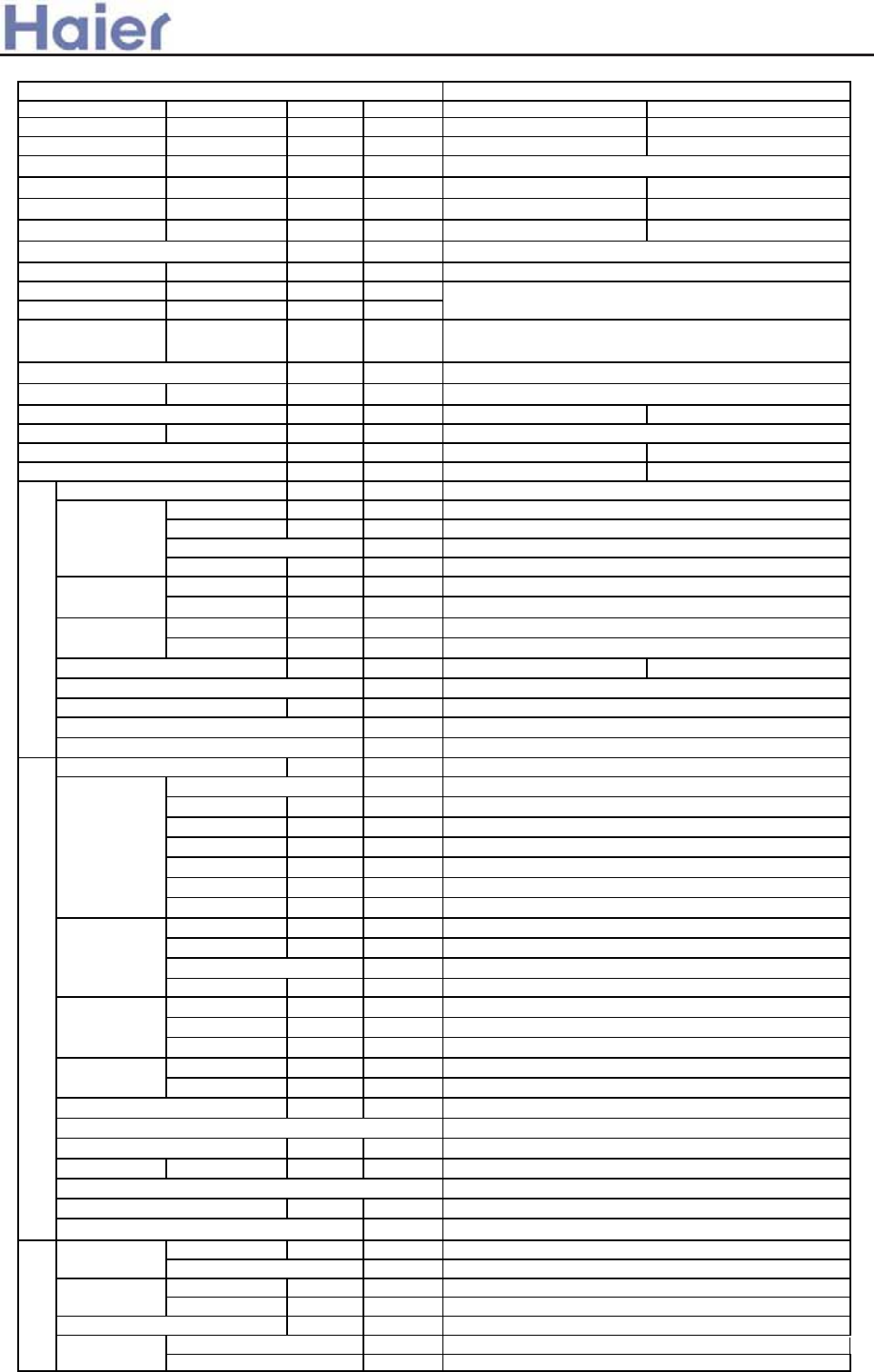
Capacity BTU/h 42000 47800
Capacity kW 12.3 14.0
Sensible heat ratio
W4800 5050
W 5650 6550
EER or COP W/W 2.55 2.7
Dehumidifying capacity 10ϋ³×m³/h
Power cable section
Signal cable section
Connecting cable section
Power source N, V, Hz
A / A
Start Current A
Class of anti electric shock &/$66, &/$66,
Circuit breaker A
Max. operating pressure of heat side Mpa 4.15 4.15
Max. operating pressure of cold side Mpa 4.15 4.15
Unit model (color)
Type × Number
Speed(H-M-L) r/min
Fan motor output power kW
Air-flow(H-M-L) m³/h
Type / Diameter mm
Temp. scope ć
External ˄L×W×H˅mm×mm×mm
Package ˄L×W×H˅mm×mm×mm
Air sending angle 160 160
Control type (Remote /wired /model)
Outlet distribution hole dimension mm
dB(A)
kg / kg
Unit model (color)
Model / Manufacture
Oil model
Oil type
Oil charging
Type
Protection type
Starting method
Type × Number
Speed r/min
Fan motor output power kW
Air-flow(H-M-L) m³/h
Type / Diameter mm
Row / Fin pitch
Temp. scope ć
External ˄L×W×H˅mm×mm×mm
Package ˄L×W×H˅mm×mm×mm
Refrigerant control method mm/mm
Volume of Accumulator L
Noise level dB(A)
crankcase heater power W
kg / kg
Type / Charge g
Recharge quantity g/m
Liquid mm
Gas mm
Connecting Method
m
m
item Model AU42NALEAA/AP422ACEAA
Total power input
Max. power input
70%
5.0
5G×2.5mm2
4G×0.75mm2
OUTDOOR UNIT: 3N, 380-400V, 50HZ INDOOR UNIT: 1PH,
220-230AC, 50HZ
Cooling 8.4A/9.9A Heating 8.8/11.5A
50
20
Running /Max.Running current
Fan
centrifugal
540/380/320
0.1
1560
2ˉ7
Dimension 1820× 530× 310
1905×625×415
Heat exchanger inner grooved/¶7
Remote
70
Noise level (H-M-L) 56/46/40
Weight (Net / Shipping) 52/61
Indoor unit
AP422ACEAA(WHITE)
Outdoor unit
AU42NALEAA(WHITE)
Compressor
JT160G-P8Y1(R410A) /DAKIN
DAPHNE
FVC68D
1500L
SCROLL
Inner thermal protection
hard startup
Fan
Axial*1
740
0.15*1
5500
Heat exchanger
inner grooved/¶9.52
2/1.6
43ˉ60
Dimension 1008×447×830
1130×490×930
Capillary tube
Defrosting Automatic
2.5
59
Type of Four way valve SHF
55
Weight (Net / Shipping) 91/102
PIPING
Refrigerant R410A/3100
65
Pipe ¶9.52
¶19.05
Flared
Between I.D &O. MAX.Drop 30
MAX.Pi
p
in
g
len
g
th 50
>a__WcU[S^<[c>a`V[e[a`Wc
Function cooling heating
Capacity kW 13.6 16.5
Sensible heat ratio 0.72
W4500 5000
W5500 6000
EER or COP W/W 3.02˄B˅3.3˄C˅
Dehumidifying capacity 10ϋ³×m³/h
A / A 8.0A/9.5A 9.0A/10.5A
Start Current A 65 65
Unit model (color)
Type × Number
Air-flow(H-M-L) m³/h
Type / Diameter mm
Temp. scope ć
External ˄L×W×H˅mm×mm×mm
Package ˄L×W×H˅mm×mm×mm
Drainage pipe (material , I.D./O.D.) mm
Control type (Remote /wired)
dB(A)
kg / kg
External ˄L×W×H˅mm×mm×mm
Package ˄L×W×H˅mm×mm×mm
kg / kg
Function cooling heating
Capacity kW 14.06 17.0
Sensible heat ratio 0.72
W4600 4950
W5500 6000
EER or COP W/W 3.06˄B˅3.43˄B˅
Dehumidifying capacity 10ϋ³×m³/h
A / A 8.0A/9.5A 9.0A/10.5A
Start Current A 65 65
Unit model (color)
Type × Number
Speed(H-M-L) r/min
Fan motor output power kW
Air-flow(H-M-L) m³/h
Type / Diameter mm
Total Area m²
Temp. scope ć
External ˄L×W×H˅mm×mm×mm
Package ˄L×W×H˅mm×mm×mm
Drainage pipe (material , I.D./O.D.) mm
Control type (Remote /wired)
dB(A)
kg / kg
item Model AB482ACEAA
Total power input
Max. power input
5.0
Running /Max.Running current
Fan centrifugal fan*1
1980/-/-
Heat exchanger inner grooved pipe/ij7
2-7
Dimension 1230/840/280
1325/920/370
PVC 32/26
Remote /wired (optional)
Indoor unit
AB482ACEAA˄BLACK)
Noise level (H-M-L) 51/47/43
Weight (Net / Shipping) 46/53
Panel
Dimension 1340/950/80
1400/995/115
Weight (Net / Shipping) 8.4/12.0
item Model AC482AFEAA
Total power input
Max. power input
5.3
2-7
1710/790/315
Heat exchanger
inner grooved pipe/ij7
0.10
PVC
Remote
Indoor unit
AC482AFEAA˄WHITE)
Fan
centrifugal fan*4
1250/1150/1100
0.09
Weight (Net / Shipping) 54/61
Running /Max.Running current
Noise level (H-M-L) 53/51/49
2000/1800/1400
Dimension 1580/700/240
-37-
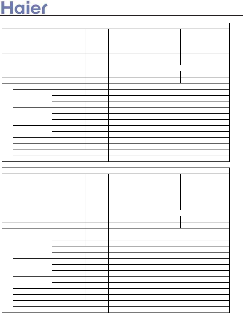
>a__WcU[S^<[c>a`V[e[a`Wc
Function cooling heating
Capacity kW 14.06 17.5
Sensible heat ratio 0.72
W4600 4800
W5500 6000
EER or COP W/W 3.06˄B˅3.65˄A˅
Dehumidifying capacity 10ϋ³×m³/h
A / A 8.0A/9.5A 8.5A/10.5A
Start Current A 65 65
Unit model (color)
Type × Number
Fan motor output power kW
Air-flow(H-M-L) m³/h
Type / Diameter mm
Total Area m²
Temp. scope ć
External ˄L×W×H˅mm×mm×mm
Package ˄L×W×H˅mm×mm×mm
Drainage pipe (material , I.D./O.D.) mm
Control type (Remote /wired)
dB(A)
kg / kg
Function cooling heating
Capacity kW 13.5 17.5
Sensible heat ratio 0.72
W4600 4700
W5500 6000
EER or COP W/W 2.96˄C˅3.72˄A˅
Dehumidifying capacity 10ϋ³×m³/h
A / A 8.0A/9.5A 8.5A/10.5A
Start Current A 65 65
Unit model (color)
Type × Number
Speed(H-M-L) r/min
Fan motor output power kW
Air-flow(H-M-L) m³/h
Type / Diameter mm
Total Area m²
Temp. scope ć
External ˄L×W×H˅mm×mm×mm
Package ˄L×W×H˅mm×mm×mm
Drainage pipe (material , I.D./O.D.) mm
Control type (Remote /wired)
dB(A)
kg / kg
Indoor unit
grey
Fan
centrifugal fanX3
0.06
2040/1800/1600m³/h
Running /Max.Running current
4.8
wired
2-7
Total power input
Max. power input
item Model AD482AMEAA
Heat exchanger
TP2M/9.52
0.10
2-7
Dimension 1410/635/350
1557/800/370
PVC 26/32
item Model AD482AHEAA
Noise level (H-M-L) 48/-/44
Weight (Net / Shipping) 55/60
Total power input
Max. power input
4.2
2580/-/1560
Heat exchanger
TP2M/9.52
0.10
PVC 26/32
wired
Weight (Net / Shipping) 62/70
Indoor unit
AD482AHEAA˄grey)
Fan
centrifugal fan X2
Running /Max.Running current
Noise level (H-M-L) 50/46/42
Dimension 1197×830×350
1430×940×420
1090+30/-/930+50
0.06
-38-
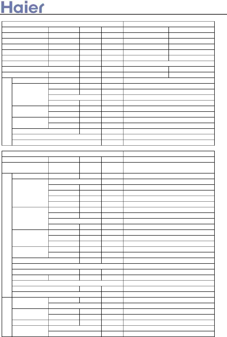
>a__WcU[S^<[c>a`V[e[a`Wc
Function cooling heating
Capacity kW 13.6 16.0
Sensible heat ratio 0.72
W4500 5250
W5500 6000
EER or COP W/W 3.02˄B˅3.05˄D˅
Dehumidifying capacity 10ϋ³×m³/h
A / A 8.0A/9.5A 9.0A/10.5A
Start Current A 65 65
Unit model (color)
Type × Number
Speed(H-M-L) r/min
Fan motor output power kW
Air-flow(H-M-L) m³/h
Type / Diameter mm
Temp. scope ć
External ˄L×W×H˅mm×mm×mm
Package ˄L×W×H˅mm×mm×mm
Control type (Remote /wired)
dB(A)
kg / kg
Power cable
Power source N, V, Hz
Unit model (color)
Model / Manufacture
Oil model
Oil type
Oil charging
Type
Type × Number
Speed r/min
Fan motor output power kW
Air-flow(H-M-L) m³/h
Type / Diameter mm
Row / Fin pitch
Temp. scope ć
External ˄L×W×H˅mm×mm×mm
Package ˄L×W×H˅mm×mm×mm
Refrigerant control method mm/mm
Volume of Accumulator L
Noise level dB(A)
crankcase heater power W
kg / kg
Type / Charge g
Recharge quantity g/m
Liquid mm
Gas mm
Connecting Method
m
m
5.5
Total power input
Max. power input
item Model AP482AKEAA
H07RN-F 5G 4.0mm2
OU:380-400V,3N,50HZ IU:1PH,220-
230V,50HZ
Indoor unit
AP482AKEAA˄white)
Fan
centrifugal fan X1
460/430/400±40
0.06
1750/-/-m³/h
TP2M/7.0
2-7
Dimension 948*340*1250
1050*440*1375
1850×600×350
1980×660×420
Heat exchanger
TP2M/9.52
3/1.55
43-60
axial×2
860±40
0.08
7000
51/48/44
Weight (Net / Shipping) 59/70
Remote
DAPHNE
FVC68D
1500CM3
Rotary
Running /Max.Running current
item Model
Outdoor unit
Noise level (H-M-L)
Fan
Dimension
Heat exchanger
PIPING
3
60
Type of Four way valve SHF-4-10A
Refrigerant R410A/3700
65
Pipe 9.52
19.05
flare
Between I.D &O.D MAX.Drop 30
MAX.Piping length 50
AU48NAIEAA
55
Weight (Net / Shipping) 106/111
capillary 2.4*150
Defrosting AUTO
WHITE
Compressor
JT160G-P8Y1˄DAIKIN˅
-39-

>a__WcU[S^<[c>a`V[e[a`Wc
Function cooling heating
Capacity kW 15.5 18.5
Sensible heat ratio 0.72
W5100W 5350W
W6200W 6200W
EER or COP W/W 3.02˄B˅3.44˄B˅
Dehumidifying capacity 10ϋ³×m³/h
A / A 9.0A/10.5A 9.5A/10.5A
Start Current A 65 65
Unit model (color)
Type × Number
Air-flow(H-M-L) m³/h
Type / Diameter mm
Temp. scope ć
External ˄L×W×H˅mm×mm×mm
Package ˄L×W×H˅mm×mm×mm
Drainage pipe (material , I.D./O.D.) mm
Control type (Remote /wired)
dB(A)
kg / kg
External ˄L×W×H˅mm×mm×mm
Package ˄L×W×H˅mm×mm×mm
kg / kg
Function cooling heating
Capacity kW 16.1 18.5
Sensible heat ratio 0.72
W5100W 5350W
W6200W 6200W
EER or COP W/W 3.16(B) 3.46(B)
Dehumidifying capacity 10ϋ³×m³/h
A / A 9.0A/10.5A 9.5A/10.5A
Start Current A 65 65
Unit model (color)
Type × Number
Speed(H-M-L) r/min
Fan motor output power kW
Air-flow(H-M-L) m³/h
Type / Diameter mm
Total Area m²
Temp. scope ć
External ˄L×W×H˅mm×mm×mm
Package ˄L×W×H˅mm×mm×mm
Drainage pipe (material , I.D./O.D.) mm
Control type (Remote /wired)
dB(A)
kg / kg
5.5
Total power input
item Model AB602ACEAA
Max. power input
5.0
2-7
Dimension 1230/840/280
1325/920/370
Heat exchanger inner grooved pipe/ij7
PVC 32/26
Remote /wired (optional)
Total power input
Max. power input
Indoor unit
AB602ACEAA˄black)
Fan centrifugal fan*1
1980/-/-
Noise level (H-M-L) 51/47/43
item Model AC602AFEAA
Heat exchanger
Weight (Net / Shipping) 46/53
Panel
Dimension 1340/950/80
1400/995/115
Weight (Net / Shipping) 8.4/12.0
Fan
centrifugal fan*4
1250/1150/1100
0.09
2000/1800/1400
inner grooved pipe/ij7
0.10
2-7
Dimension 1580/700/240
1710/790/315
Indoor unit
Noise level (H-M-L) 53/51/49
AC602AFEAA˄WHITE)
PVC
Remote /wired (optional)
Weight (Net / Shipping) 54/61
Running /Max.Running current
Running /Max.Running current
-40-
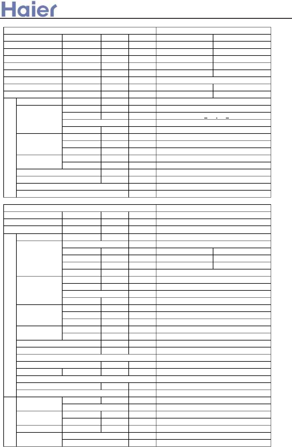
>a__WcU[S^<[c>a`V[e[a`Wc
Function cooling heating
Capacity kW 16.1 18.7
Sensible heat ratio 0.72
W5350W 5100W
W6200W 6000W
EER or COP W/W 3.01(B) 3.67(A)
Dehumidifying capacity 10ϋ³×m³/h
A / A 9.5A/10.5A 9.0A/10
Start Current A 65 65
Unit model (color)
Type × Number
Speed(H-M-L) r/min
Fan motor output power kW
Air-flow(H-M-L) m³/h
Type / Diameter mm
Total Area m²
Temp. scope ć
External ˄L×W×H˅mm×mm×mm
Package ˄L×W×H˅mm×mm×mm
Drainage pipe (material , I.D./O.D.) mm
Control type (Remote /wired)
dB(A)
kg / kg
Power source N, V, Hz
Unit model (color)
Model / Manufacture
Oil model DAPHNE
Oil type FVC68D
Oil charging 1500CM3
Type
Type × Number
Speed r/min
Fan motor output power kW
Air-flow(H-M-L) m³/h
Type / Diameter mm
Row / Fin pitch
Temp. scope ć
External ˄L×W×H˅mm×mm×mm
Package ˄L×W×H˅mm×mm×mm
Drainage pipe (material , I.D./O.D.) mm
Refrigerant control method mm/mm
Volume of Accumulator L
Noise level dB(A)
crankcase heater power W
kg / kg
Type / Charge g
Recharge quantity g/m
Liquid mm
Gas mm
Connecting Method
m
m
4.8
Total power input
Max. power input
item Model AD602AHEAA
1430×940×420
PVC 26/32
2580/2070/1560
Heat exchanger
TP2M/9.52
0.10
2-7
/
capillary ĭ2.4*150
Noise level (H-M-L) 50/46/42
Dimension 948*340*1250
1050*440*1375
Weight (Net / Shipping) 62/70
Indoor unit
AD602AHEAA˄grey)
Fan
centrifugal X2
1090+30/-/930+50
0.06
wired control
Dimension 1197×830×350
Power cable H07RN-F 5G 4.0mm2
connectting cable H05RN-F 4G 0.75mm2
OU: 380-400V, 3N, 50HZ IU:1PH, 220-230V,
50HZ
0.08
7000
item Model AU60NAIEAA
Heat exchanger
TP2M/9.52
3/1.5
43-60
Outdoor unit
WHITE
Compressor
JT170G-P8Y1˄DAIKIN˅
Rotary
Fan
axial×2
860±40
Type of Four way valve SHF-4-10A
55
Defrosting AUTO
3
60
Weight (Net / Shipping) 106/111
PIPING
Refrigerant R410A/4050
65
Pipe 9.52
19.05
flare
Between I.D &O.D MAX.Drop 30
MAX.Piping length 50
Running /Max.Running current
-41-
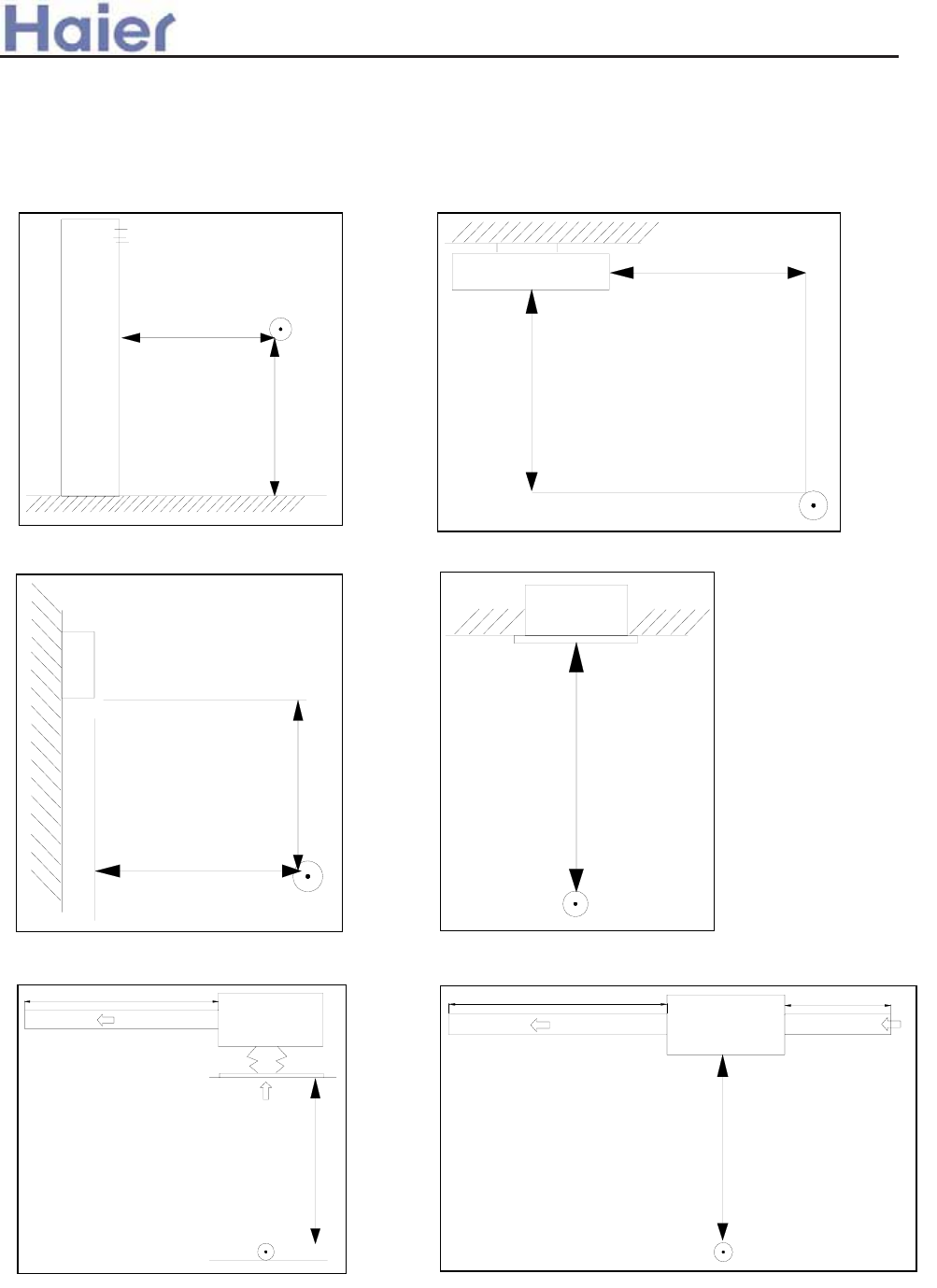
>a__WcU[S^<[c>a`V[e[a`Wc
duct unit without auxiliary duct: duct unit with auxiliary duct:
Installation state: the unit should be placed on the flat floor or be mounted in horizontal direction.
Testing method:
standing-on-floor unit: If the unit cooling capacity is
over 28000W, the noise level should be measured at
the front, left, right directions respectively.
mounting-on-ceiling unit:
mounting-on-wall unit: built-in-ceiling unit:
1m
1m
1m
1m
0.8m
1m
1.4m
1.4m
2m
duct
auxiliary duct
2m
1.4m
1m
auxiliary duct
-42-
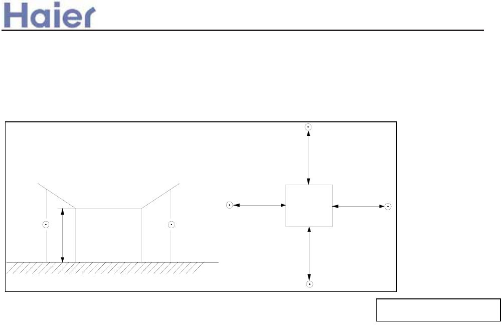
>a__WcU[S^<[c>a`V[e[a`Wc
Note: Ĵ is the real time
analyser position
outdoor unit:
1.air outlet from side: the noise level is the average sound pressure level measured from front, left, right directions.
2.air outlet from top: the noise level is the average sound pressure level measured from front, back, left, right directions.
measured point:
H ( height to the ground) = (h (unit height) + 1m) /2
and, it is 1m to each side.
h
1m
1m
1m
1m
Note: All the data in the specifications for 28, 36, 42 series is only for reference, the information
is subject to change without notice.
-43-
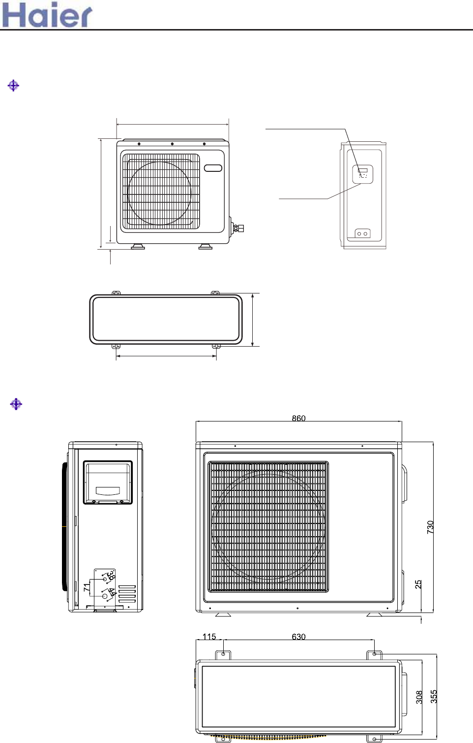
>a__WcU[S^<[c>a`V[e[a`Wc
3. Dimension
AU182AEAA
3.1 Outdoor unit dimension
6AF;B 8=B=@< 7;B?=@9>
6AF;B 8=B=@<
4=CDB=:ED=A@ 5A>;
-0
23+
1/+
0++
-2+
AU242AGEAA, AU242AGERA
-44-
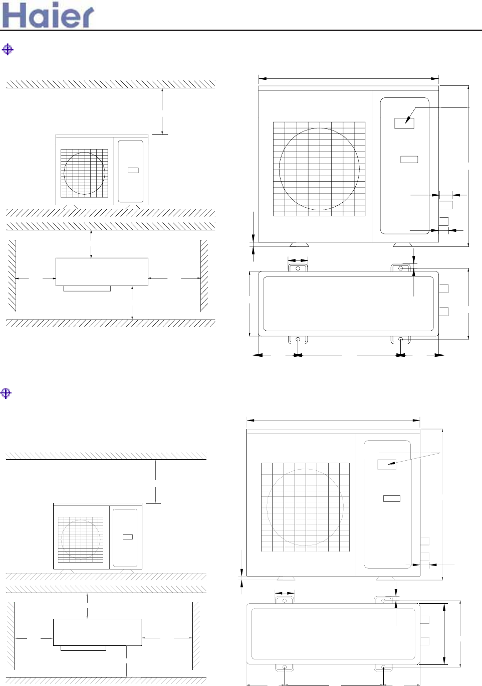
>a__WcU[S^<[c>a`V[e[a`Wc
!
184
!
340
580
!
!
!
70
Power wiring terminal
25
18
55
948
70
184
380
840
410
Power wiring terminal
20
20
60
1006
70
180
447
825
!
180
!
646
!
!
!
AU42NALEAA
(4xM10)
AU282AHEAA, AU28NAHEAA, AU362AHERA
-45-
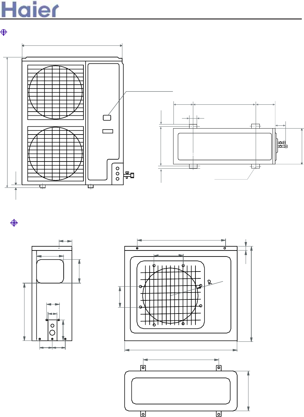
>a__WcU[S^<[c>a`V[e[a`Wc
948
1250
25
Power wiring Terminal
184 184
55
Screw Hole
580
70
380 18
340
18
(4xM10)
AU182AFERA
75
65
150
100 100
110
190
170
400
480
30
265
220
200
810
680
580
288
AU362AIEAA, AU36NAIEAA, AU48NAIEAA, AU60NAIEAA
-46-
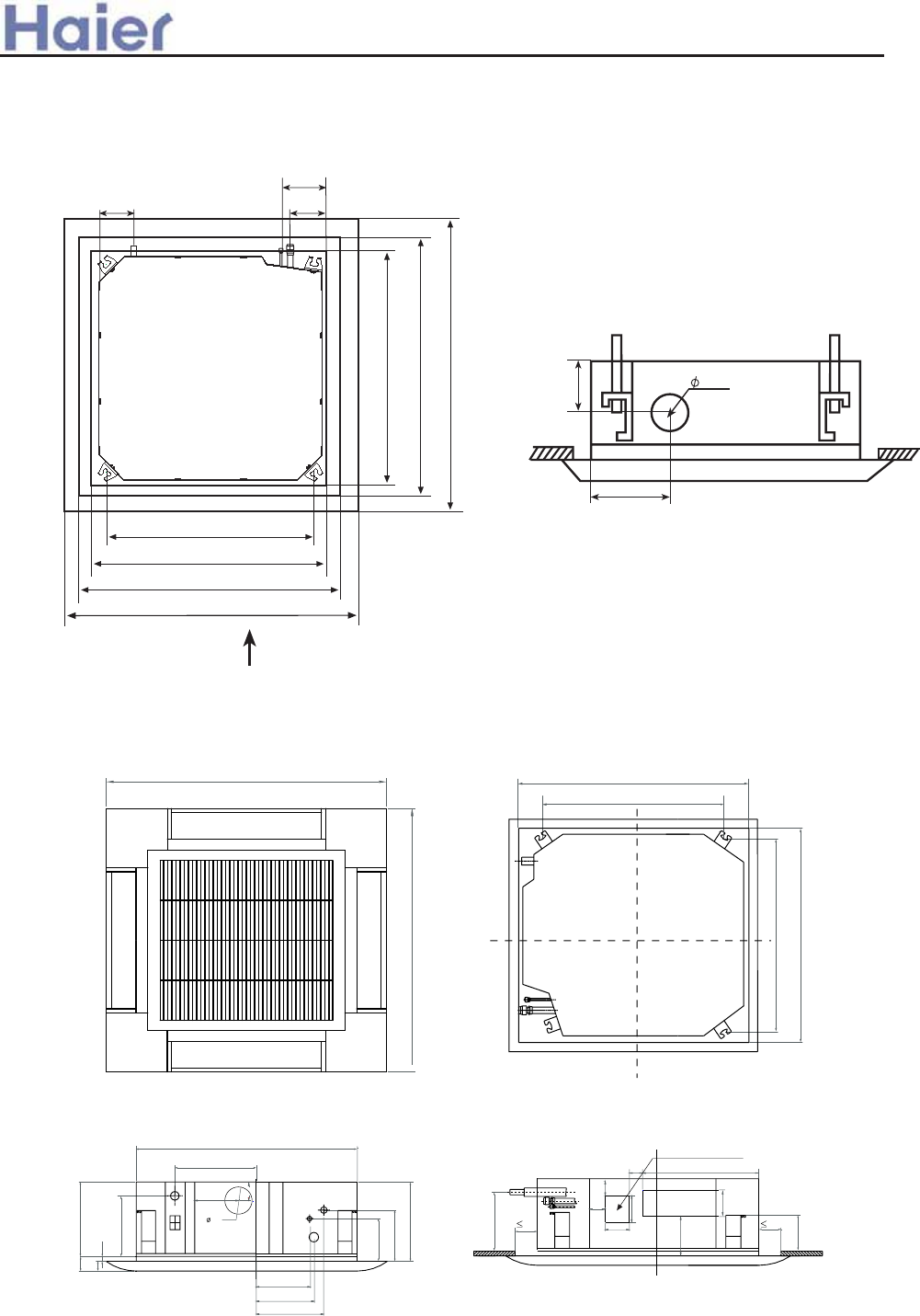
>a__WcU[S^<[c>a`V[e[a`Wc
3.2 Indoor unit dimension
(mm)
950
950
840
295
240
180
50
30
20
135
160
260
860-890 (ceiling hole)
680 (hang position)
860-890
680
(mm)
260
270
315
140
200
80
30
180
57
155
35
57
85
85
345
103
35
106
air discharge hole
B9 A9
:;9
GFEH D
><>SS 7JMZ]MMT Y[YVMTYQUT VURMY8
LXIQTIOM VQVM OIY VQVMRQW[QL VQVM
>@9SS 7QTLUUX [TQZ LQSMTYQUT8
?>9SS 7KMQRQTO UVMTQTO LQSMTYQUT8
@99SS 7VITMR LQSMTYQUT8
>@9SS 7QTLUUX [TQZ LQSMTYQUT8
?>9SS 7KMQRQTO UVMTQTO LQSMTYQUT8
@99SS 7VITMR LQSMTYQUT8
B>
:=9
:A9
NXMYP IQX PURM
VIEW A
Model: AB24, AB28 (Panel: PB-950IA)
Model: AB182 (Panel: PB-700IA) (used for all 700x700 cassette type units)
-47-
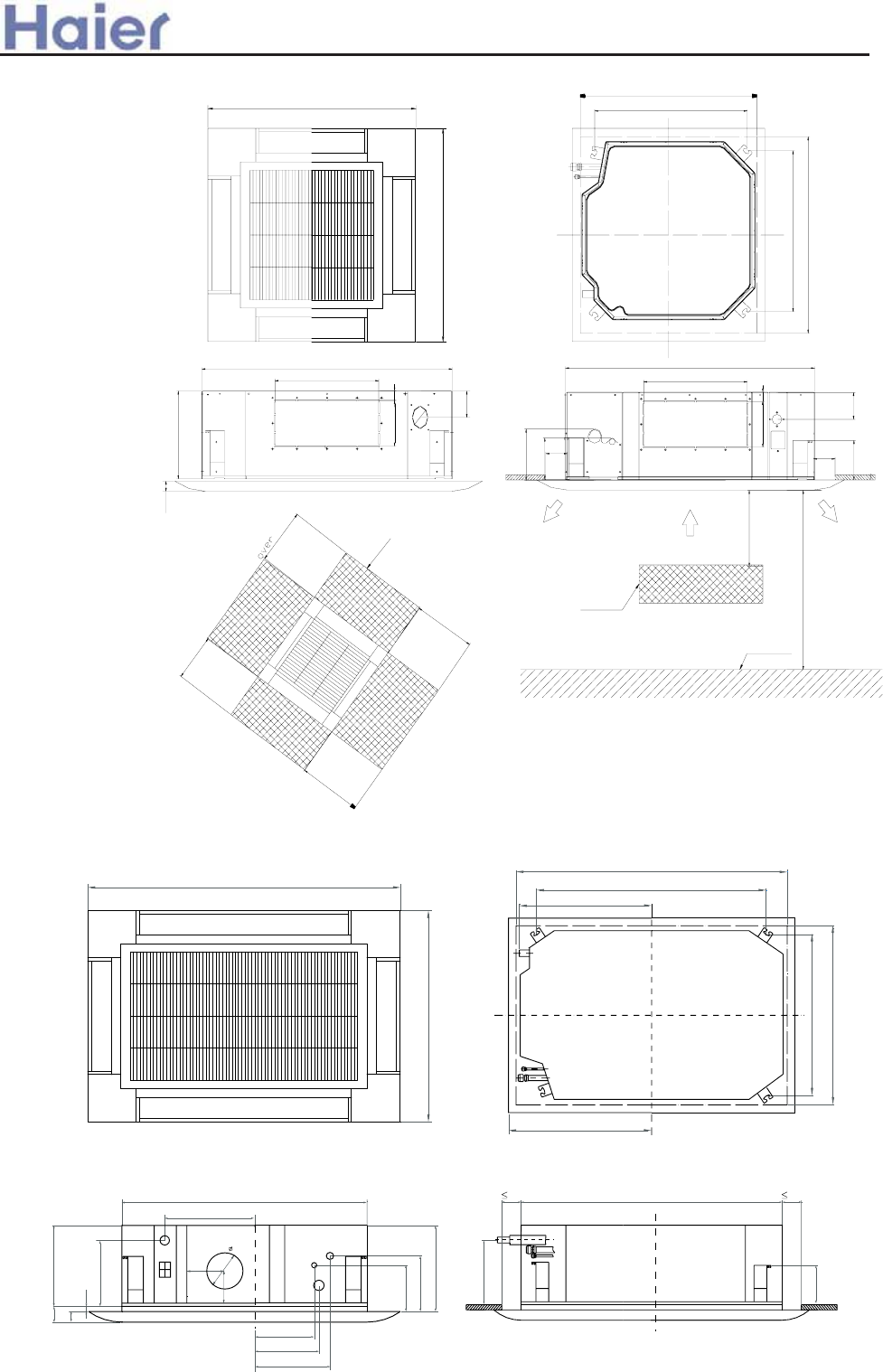
>a__WcU[S^<[c>a`V[e[a`Wc
1340
950
260
315
270
840
295
280
220
50
30
20
135
160
300
535
615
1250~1280 (ceiling hole)
860-890
780
1070 (hanging position)
220
55 1230 55
155
(mm)
90
170
120
950
690
790
860-890
860-890(ceiling hole)
1000
over
1500
1500
1500
1500
over
over
over
950
below 3000
Barrier
Ground
(Hanging position)
Wall or barrier
60
840
287
85
150
840
88
164
134
346
149 35
35
149
346
35 35
?80
Model: AB362ACEAA (Panel: PB-950JA)
Model: AB362ACERA, AB48, AB60 (Panel: PB-1340IA)
-48-
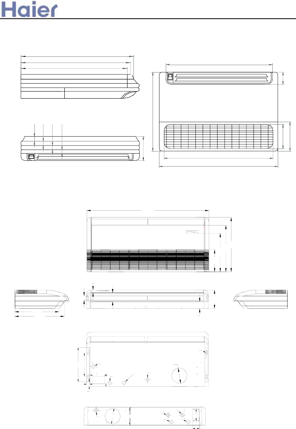
>a__WcU[S^<[c>a`V[e[a`Wc
Model: AC18, AC24
Model: AC28, AC36, AC48, AC60
240
100
900
990
655
200
880
620
605
600
40 35 35 30
199
(mm)
(mm)
224
D=50 D=200
D=47
D=47
D=47
D=47
90
155
D=25
60
300
40
440 D=47
150
95
D=47 D=47 D=47
D=200
114
36
55
90
495
598
285
640
570
240
700
1580
-49-
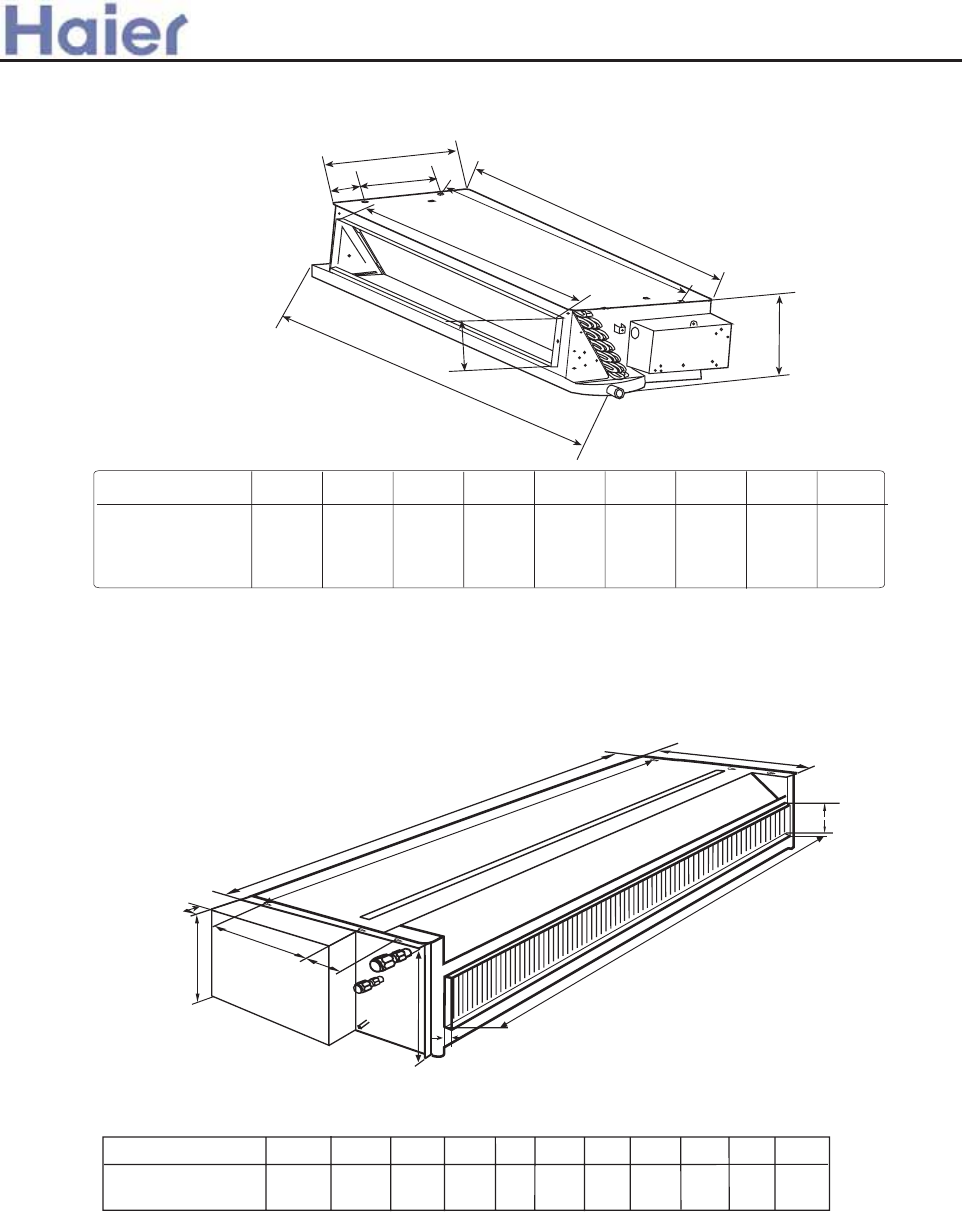
a
b
c
d
e
f
g
h
i
Unit model a
1002
b
483.5
c
131
d
1105
e
255
f
105
g
880
h
970
i
220
AD182ALEAA
AD242ALEAA
AD242ALERA
>a__WcU[S^<[c>a`V[e[a`Wc
*
G
H
I
D
F
K
L
<PRSCNNCSKQP FKOGPRKQP8 ,APKS8 OO-
@B>;
9:/609=;?9
CDEFGHIJK
/.40 //02 23.0/6 26 005 /01 /.75
75
L
00.
M
M
00
44
J
-50-
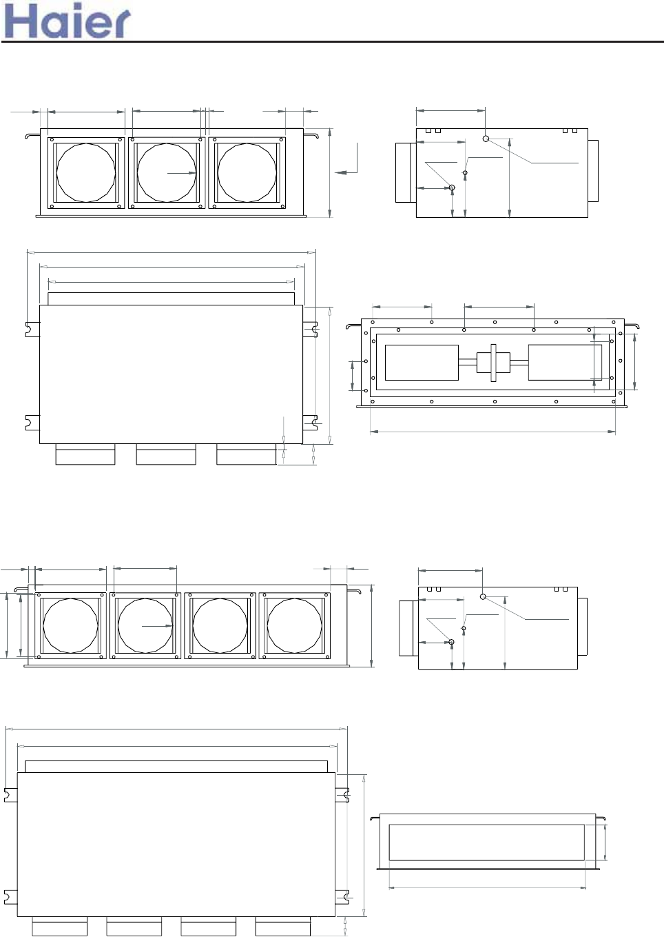
26027535
350
R100
85
260
275
A-A
gas pipe liquid pipe drainage pipe
235
165
120
100
150
265
85
545
655
1370
1406
240
1280
(mm)
>a__WcU[S^<[c>a`V[e[a`Wc
130
200
170
890
200
200
260275
A
35 10
300
R100
85
70
20
545
635
960
986
890
A-A
gas pipe liquid pipe drainage pipe
235
165
120
100
150
265
(mm)
Model: AD482AMEAA Medium static pressure
Medium static pressure duct type
Model: AD242AMEAA, AD282AMEAA, AD362AMEAA, AD242AMERA, AD362AMERA
-51-
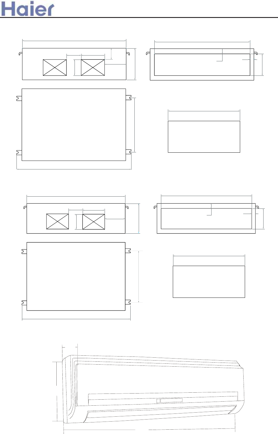
800
1320
830
1200
170 270
250
365
185
250
60 45
1105
(mm)
>a__WcU[S^<[c>a`V[e[a`Wc
870
305
Model: AS182AVERA
225
800
960
60
250
750
30
840
170 205
130
120
365
185
830
Model: AD482AHEAA, AD602AHEAA, AD362AHERA High static pressure
Model: AD282AHEAA, AD362AHEAA High static pressure
-52-
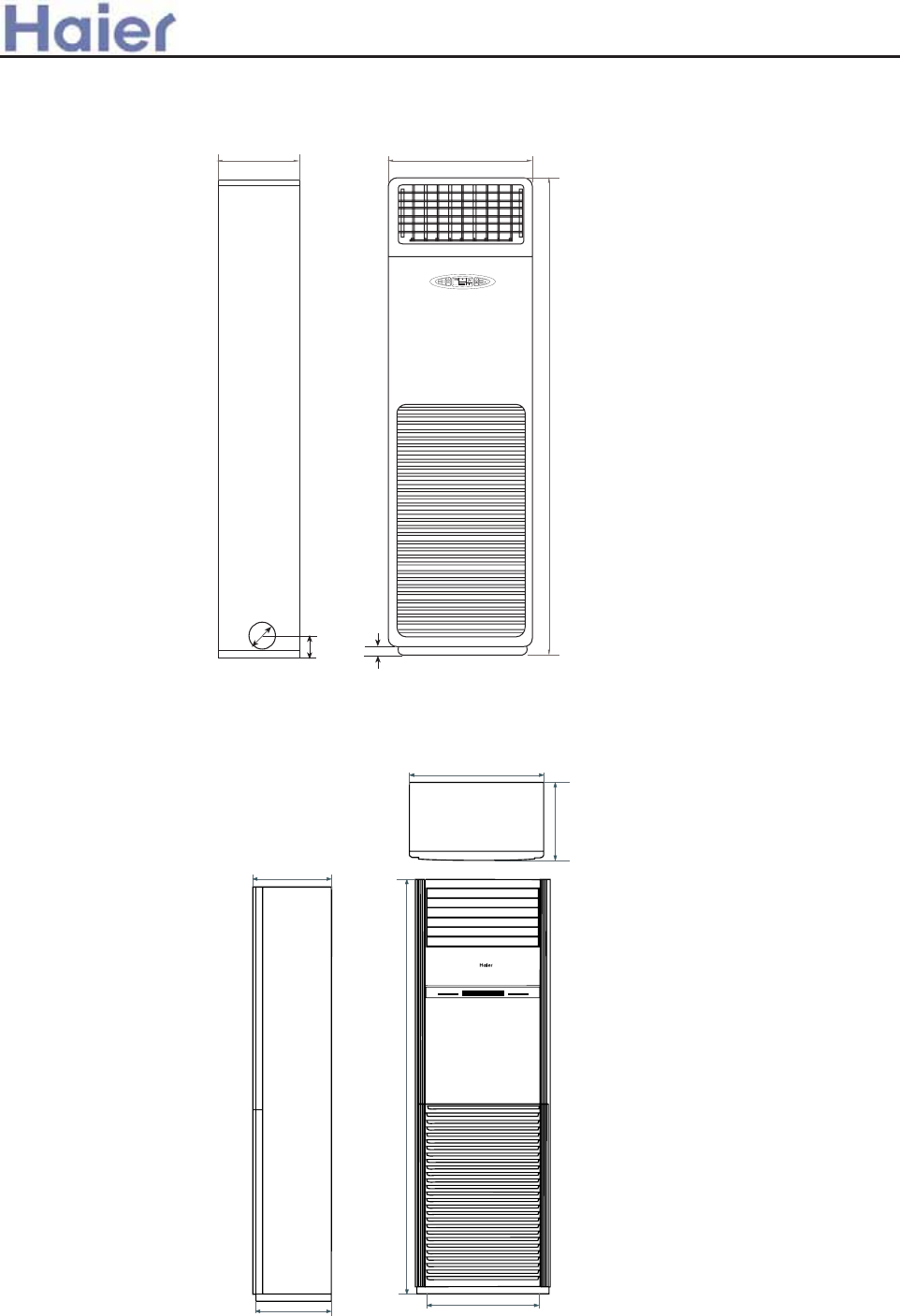
>a__WcU[S^<[c>a`V[e[a`Wc
01-
.--
.--
530
.3/-
1-
MNPOQ
5@
F=@9D
7?B7>
E9F
F=@9
F=@9
E?99C
?BG
@=8
<=;<
E9F
F9@C
7
F9@C
F9@C
EG=A;
@B89
:5AEC998
BA
B::
4
Model: AP422ACEAA
350
350
336 500
1851
600
Model: AP482AKEAA
-53-
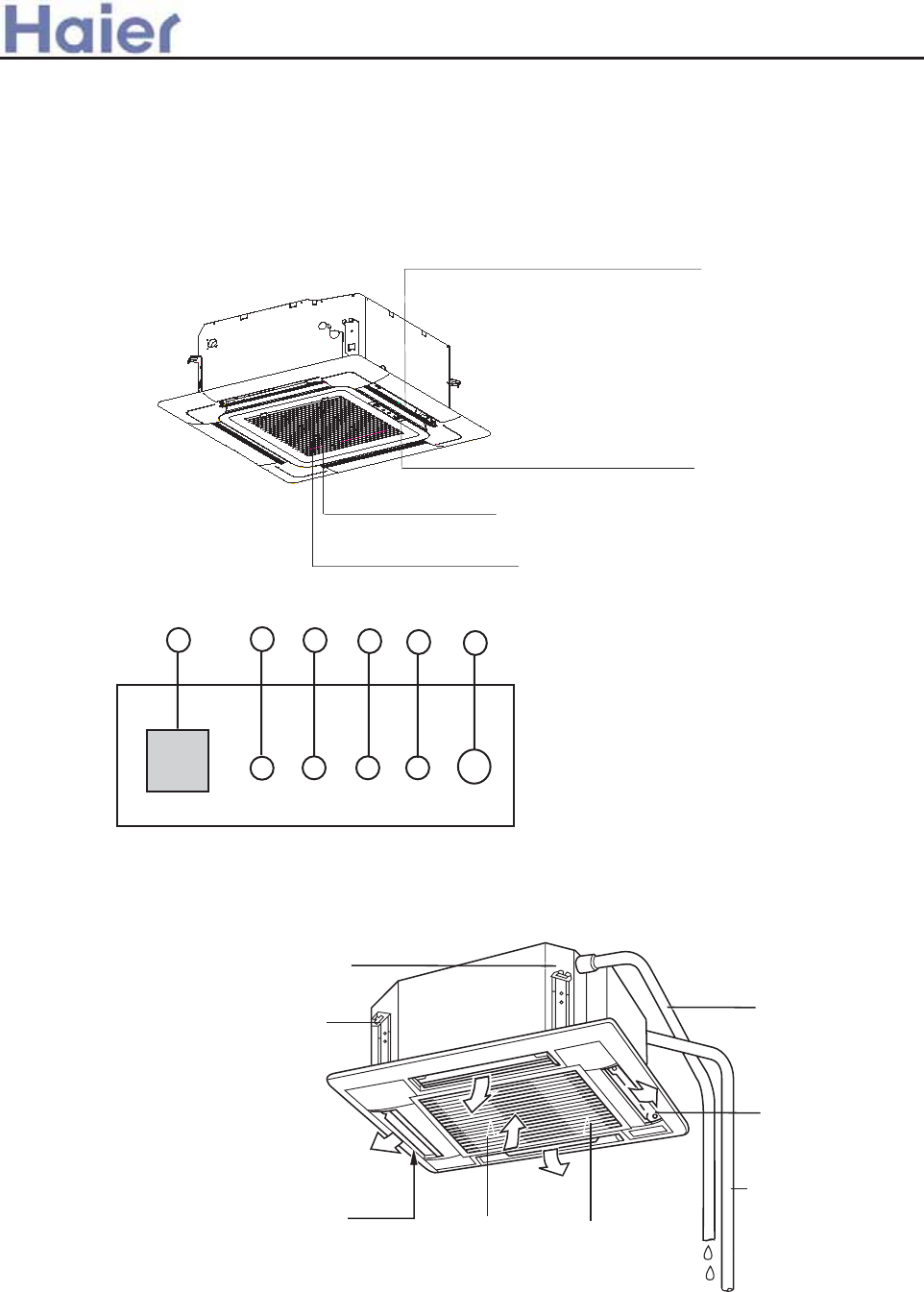
>`^^WcU[S] <[c>`_V[e[`_Wc
60JSced _S^W
IWFNS 3TXJ
X\NSL QTZ[JW
WJKWNLJWFSY UNUJ
HFGQJ QNSJ
JFWYMNSL QNSJ
FNWKNQYJW
nNSXNIJ YMJ LWNQQo
TZYQJY
FNWNSQJY LWNQQ
\FYJW UZRU nGZNQY NSo
XZXUJSXNTS GWFHPJY
>\NSL QTZ[JW
n,NW KQT\ INWJHYNTS HFS GJ FIOZXYJI G^ ZXNSL
YMJ >B492 GZYYTS TS YMJ WJRTYJ HTSYWTQQJWo
,NW4SQJY 2WNQQJ
,NW1NQYJW
n4SXNIJ TK YMJ 4SQJY 2WNQQJo
5<:=>6??<> @9:6> >A; =<B6>
./0123.- >GNPTG RGEGKVGR
/- 5<:=>6??<> MCNQ
0-@9:6> MCNQ
1- >A; MCNQ
2- =<B6> MCNQ
3- 6NGRIGOEX SWKTEJ
:UJWFYNSL .TSYWTQ ;FSJQ
AB242ACEAA, AB282ACEAA, AB242ACERA
:UJWFYNSL .TSYWTQ ;FSJQ
AB182ACEAA, AB362ACEAA, AB182ACERA
-54-
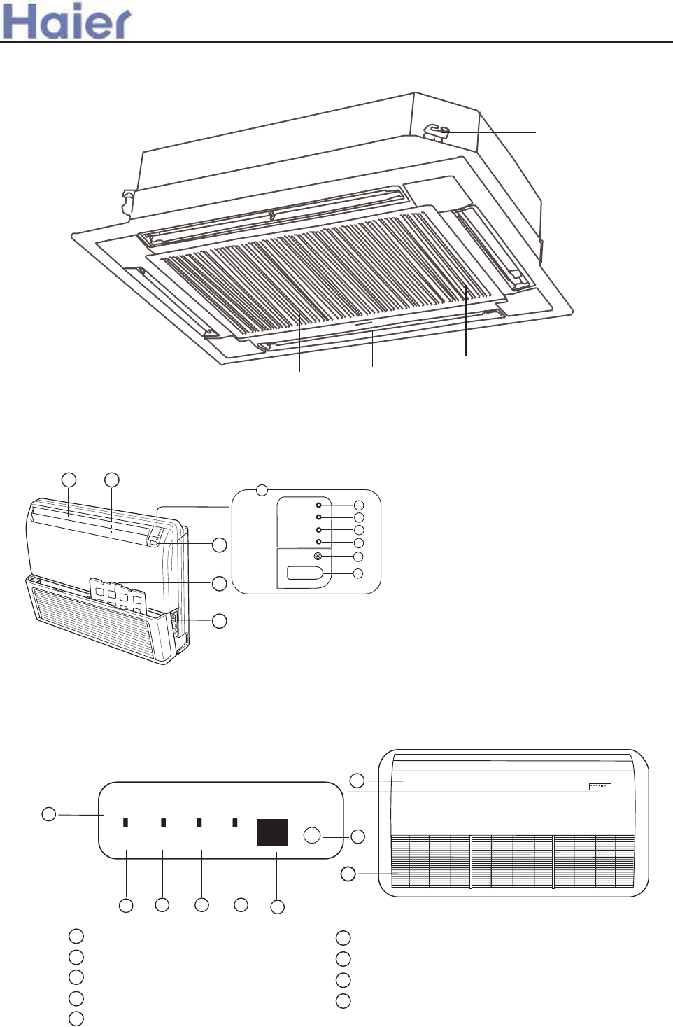
XZXUJSXNTS GWFHPJY
FNWKNQYJW
nNSXNIJ YMJ LWNQQo
FNWNSQJY LWNQQ X\NSL QTZ[JW
>`^^WcU[S]<[c>`_V[e[`_Wc
ef g
b
;:B0= :;0= ?480=
080=
c
.:8;
d
y
*
~
wwwv
w:UJWFYNSL .TSYWTQ ;FSJQ
x0RJWLJSH^ X\NYHM
y=JRTYJ .TSYWTQ >NLSFQ =JHJN[JW
z;T\JW 4SINHFYTW 7FRU
{:;0=,?4:9 4SINHFYTW 7FRU
|?480= 4SINHFYTW 7FRU
}.TRUWJXXTW =ZS 7FRU
~4SYFPJ 2WNQQ
*,NW1NQYJW
wv
@Uu/T\S ,NW/NWJHYNTS 1QFUX
ww =NLMYu7JKY ,NW/NWJHYNTS 7TZ[JWX
nGJMNSI @Uu/T\S ,NW/NWJHYNTS 1QFUXo
w
e
g
h
d
;:B0=
:;0=
?480=
.:8;
080= c
f
AB482ACEAA, AB602ACEAA, AB362ACERA
AC182ACEAA, AC242ACEAA, AC182ACERA, AC242ACERA,
AC282AFEAA, AC362AFEAA, AC482AFEAA, AC602AFEAA, AC362AFERA
h
~
~
*
1 Operating Control Panel
2 Emergency switch
3 Power Indicator Lamp
4 OPERATION Indicator Lamp
5 TIMER Indicator Lamp
6 Compressor Lamp
7 Remote receiver
8 Inlet Grill ( Filter inside )
9 Front panel
-55-
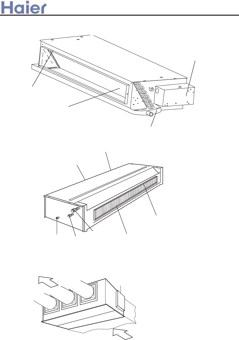
FNW TZYQJY
FNWNSQJY
JQJHYWNH HTSYWTQ FXXJRGQ^
AD182ALEAA, AD242ALEAA, AD242ALERA
Electrical components Case
Drain pan
Evaporator
Air outlet frame
>`^^WcU[S]<[c>`_V[e[`_Wc
SUZUXoOTYOJKp
LGToOTYOJKp
GOX U[ZRKZ MORRK
K\GVUXGZUX
MGY VOVK
ROW[OJ VOVK
JXGOTGMK VOVK
AD182AMERA
AD242AMEAA, AD282AMEAA, AD362AMEAA, AD242AMERA, AD362AMERA
-56-
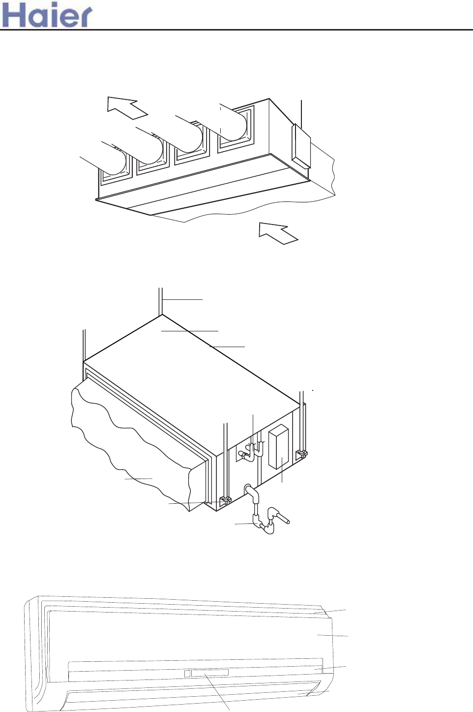
XZXUJSINSL UTQJ
LZFWINSL UQFYJ
J[FUTWFYTWnNSXNIJo
IZHY
IWFNSUNUJ
JQJHYWNHGT]
XYTU [FQ[J
XZXUJSINSL GTQY
AD282AHEAA, AD362AHEAA, AD482AHEAA, AD602AHEAA, AD362AHERA
>`^^WcU[S]<[c>`_V[e[`_Wc
Front panel
Air inlet grille
Air inlet grille
Louver
Display board
AS182AVERA
JQJHYWNHHTSYWTQFXXJRGQ^
FNW TZYQJY
FNWNSQJY
IZHY
AD482AMEAA
-57-
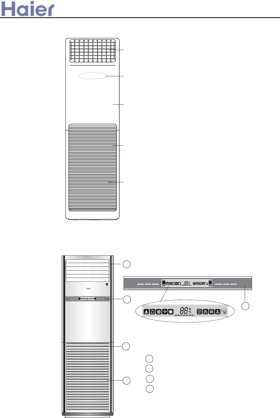
GOX U[ZRKZ MXORRK
UVKXGZOUT VGTKR
LXUTZ VGTKR
GOX OTRKZ MXORRK
GOX LORZKX oOTYOJK ZNK [TOZp
AP422ACEAA
>`^^WcU[S]<[c>`_V[e[`_Wc
**+ **
**-
1
2
3
4
2
1
2
3
4
I n d o o r u n i t
Outlet grill
Operation panel
Inlet grill
Air filter [inside the unit]
SLEEP
ON/OFF MODE FAN TEMP + TEMP - HEALTH
SET
HUMI
TEMP
HEALTH
TIMER
SLEEP
TEMP
HUMI
SET
SLEEP
TIMER
HEALTH
ON/OFF MODE FAN
SET
TEMP
HUMI
HEALTH
TIMER
AP482AKEAA
-58-
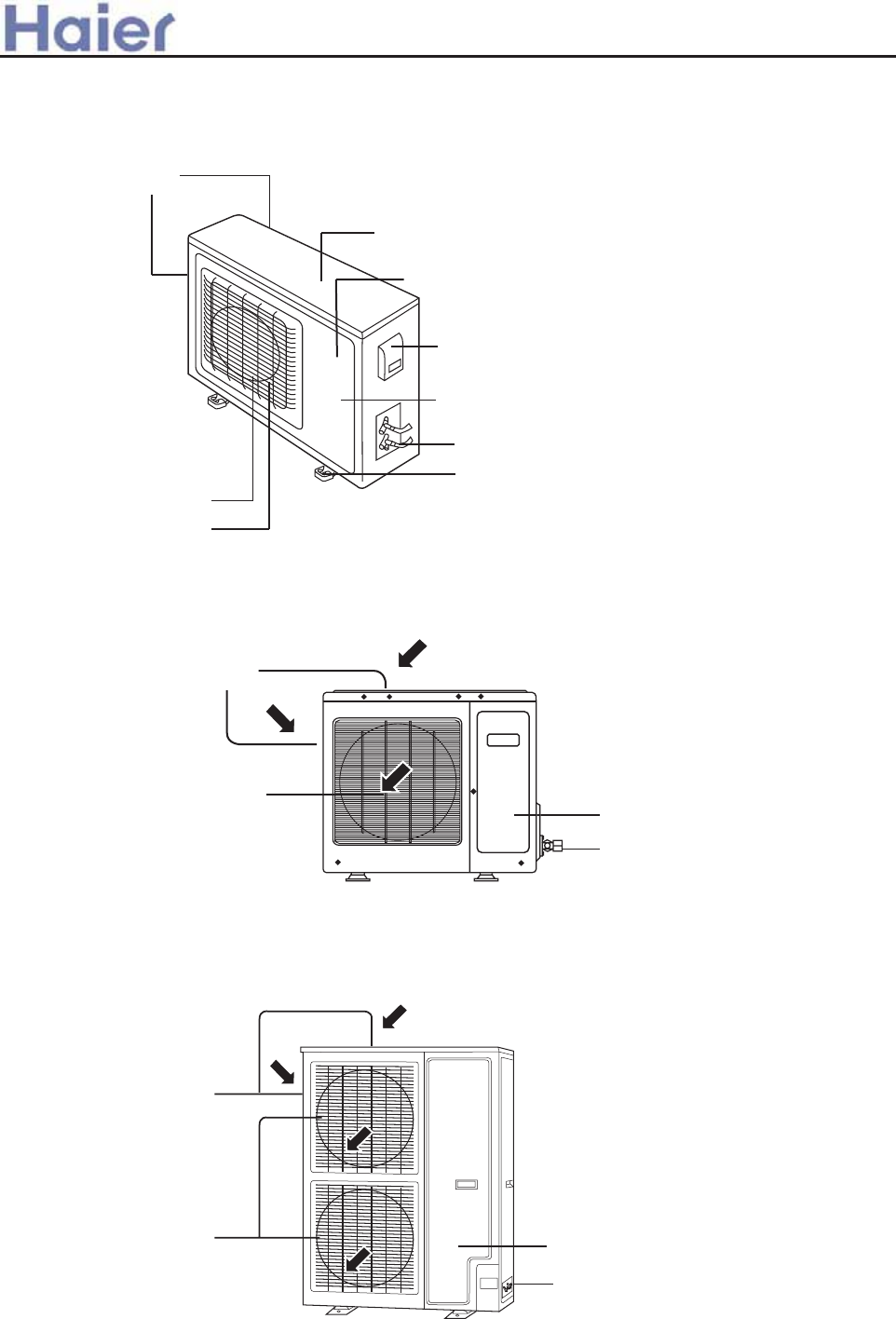
FNWNSQJY
FNW TZYQJY
HTRUWJXXTWnNSXNIJTKZSNYo
YTU HT[JW
XYTU [FQ[J
\NWNSL GT]HT[JW
FNW TZYQJY LWNQQJ
GTYYTR UQFYJ
KWTSY UFSJQ
>`^^WcU[S]<[c>`_V[e[`_Wc
XYTU [FQ[J
FNWNSQJY
FNW TZYQJY HTRUWJXXTWnNSXNIJTKZSNYo
FNWNSQJY
FNW TZYQJY LWNQQJ
XYTU [FQ[J
HTRUWJXXTWnNSXNIJTKZSNYo
AU242AGEAA, AU182AFERA, AU242AGERA
AU362AIEAA, AU36NAIEAA, AU48NAIEAA, AU60NAIEAA
AU182AEEAA, AU282AHEAA, AU28NAHEAA, AU42NALEAA, AU362AHERA
-59-
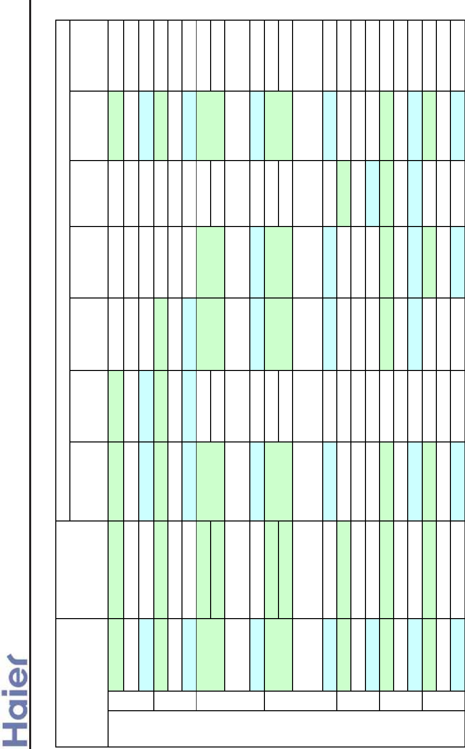
>a__WcU[S^<[c>a`V[e[a`Wc
cassette type
ceiling
concealed duct
type
midium static
pressure duct
type
high static
pressure duct
type
cabinet type convertible type wall mounted
type
Model AU182AEEAA AB182ACEAA AD182ALEAA AC182ACEAA
PCB code 0010451870E 0010452478E 0010451167E 0010451167E
Controller / 0010451255 0010451521E 0010451255
Model AU242AGEAA AB242ACEAA AD242ALEAA AD242AMEAA AC242ACEAA
PCB code 0010452442E 0010451167E 0010451167E 0010451167E 0010451167E
Controller / 0010451255 0010451521E 0010451521E 0010451255
AU282AHEAA
AU28NAHEAA
PCB code 0010452442E(2 PH)
0010452378E(3 PH) 0010451167E 0010451167E 0010451167E 0010451167E
Controller / 0010451255 0010451521E 0010451521E 0010452300
AU362AIEAA
AU36NAIEAA
PCB code 0010452442E(2 PH)
0010452378E(3 PH) 0010452478E 0010451167E 0010451167E 0010451167E
Controller / 0010451255 0010451521E 0010451521E 0010452300
Model AU42NALEAA AP422ACEAA
PCB code 0010452378E
Controller / 0010451255
Model AU48NAIEAA AB482ACEAA AD482AMEAA AD482AHEAA AP482AKEAA AC482AFEAA
PCB code 0010452378E 0010451167E 0010451167E 0010451167E 0010452322 0010451167E
Controller / 0010451255 0010451521E 0010451521E 0010451047 0010452300
Model AU60NAIEAA AB602ACEAA AD602AHEAA AC602AFEAA
PCB code 0010452378E 0010451167E 0010451167E 0010451167E
Controller / 0010451255 0010451521E 0010452300
18
42
48
24
28
36
R410A On-Off (fix frequency unit)
60
OUTDOOR UNIT
AB282ACEAA
AB362ACEAA
INDOOR UNIT
Item
Model
Model
AC282AFEAA
AC362AFEAA
AD282AMEAA
AD362AMEAA
AD282AHEAA
AD362AHEAA
-60-
0010451432
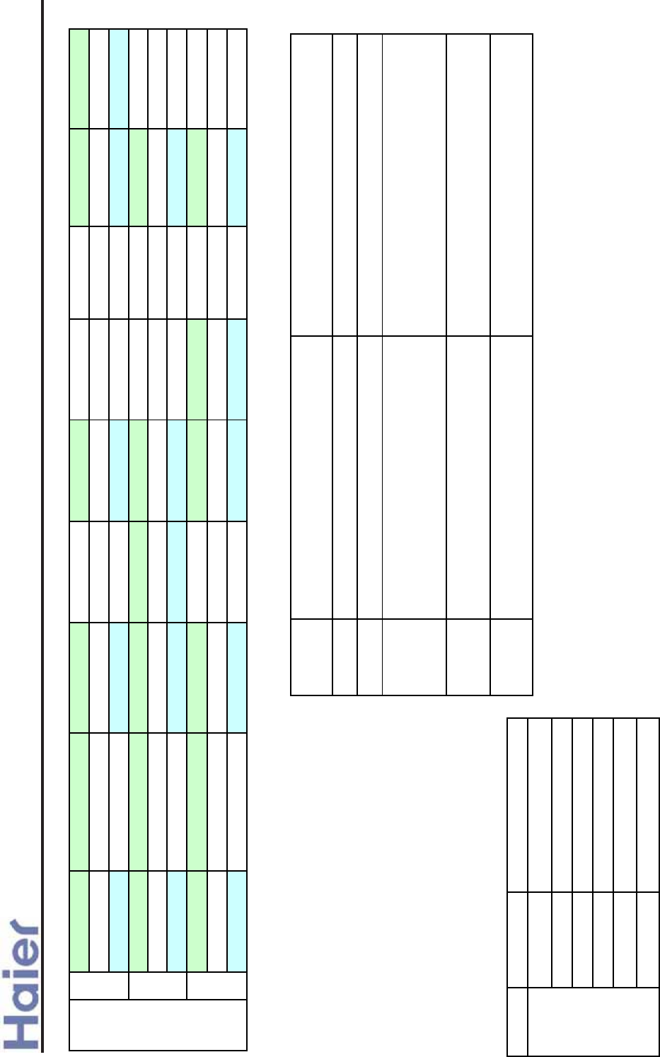
>a__WcU[S^<[c>a`V[e[a`Wc
Controller functions
single split indoor units can use YR-E12 wired
controller, or remote controller (YR-H71 is used
for AC09-24, while YR-H50 is used for AC28-
60), for cabinet type and wall mounted type, the
indoor units only can be controlled by remote
controller. YR-E12 can be used as group
controller, single split indoor units can be
connected with central controller YCZ-A001 and
weekly timer YCS-A001. Please see controller
part to know operation and installation details.
Code Type
0010451255 YR-H71 with haier logo
0010451521E YR-E12
0010451451 YR-H71 without haier logo
0010452300 YR-H50
0010451047 YR-H49 with haier logo
0010451874 YR-H49 without haier logo
Controller
Model AU182AFERA AB182ACERA AD182AMERA AC182ACERA AS182AVERA
PCB code 0010452040 0010452325E 0010451690E 0010451690E 0010452042E
Controller / 0010451255 0010451521E 0010451255 0010451047
Model AU242AGERA AB242ACERA AD242ALERA AD242AMERA AC242ACERA
PCB code 0010452040 0010451690E 0010451690E 0010451690E 0010451690E
Controller / 0010451255 0010451521E 0010451521E 0010451255
Model AU362AHERA AB362ACERA AD362AMERA AD362AHERA AC362AFERA
PCB code 0010452929 0010451690E 0010451690E 0010451690E 0010451690E
Controller 0010451255 0010451521E 0010451521E 0010452300
R410A
DC
Inverter
36
24
18
For cassette type, duct type, convertible type,
Panel types features:
panel
model model function description applicable unit
PB-700IA with elevating function, for 700*700 panel single split fixed frequency&inverter AB09~18
PB-700IB without elevating function, for 700*700 panel multi split& MRV AB07~18
PB-950IA for 950*950 panel, universal for wired
control type and infrared control type
single split fixed frequency&inverter AB24~28,
R407C multi split 21~28, R22 multi split
21~42, R410A multi split 21, MRV 18~28
PB-950JA for 950*950 panel, universal for wired
control type and infrared control type New design cassette unit
PB-1340IA for 1340*1340 panel, universal for wired
control type and infrared control type
single split fixed frequency AB36~60, R407C
free multi 42, MRV 32~45
-61-
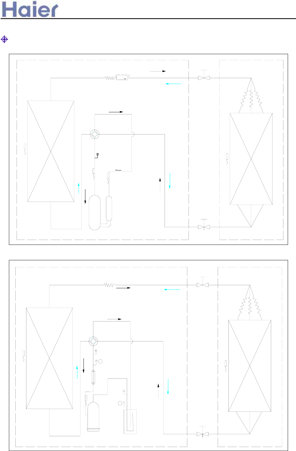
>a__WcU[S^<[c>a`V[e[a`Wc
5. Refrigerant Diagram
Fixed frequency units
For AU182AEEAA
1. high pressure switch 2. low pressure switch
cooling
heating
evaporator
indoor coil temp. sensor
3-way stop
valve
suction temp. sensor
discharging temp.
sensor
maintenance
valve
4-way valve
single check
valve
main
capillary
sub-capillary
compressor
stop valve
condenser
defrost temp. sensor
muffle
compressor air-liquid
segregator
check valve
check
valve
4-way valve
3-way stop
valve (air side)
coil
temp.
sensor
evaporator
2
1
capillary
3-way stop
valve (liquid
side)
cooling heating
defrost
temp.
sensor
condenser
discharging temp. sensor
heater
:
-62-
For AU242AGEAA, AU282/28NAHEAA, AU362/36NAIEAA, AU42NALEAA, AU48N/60NAIEAA
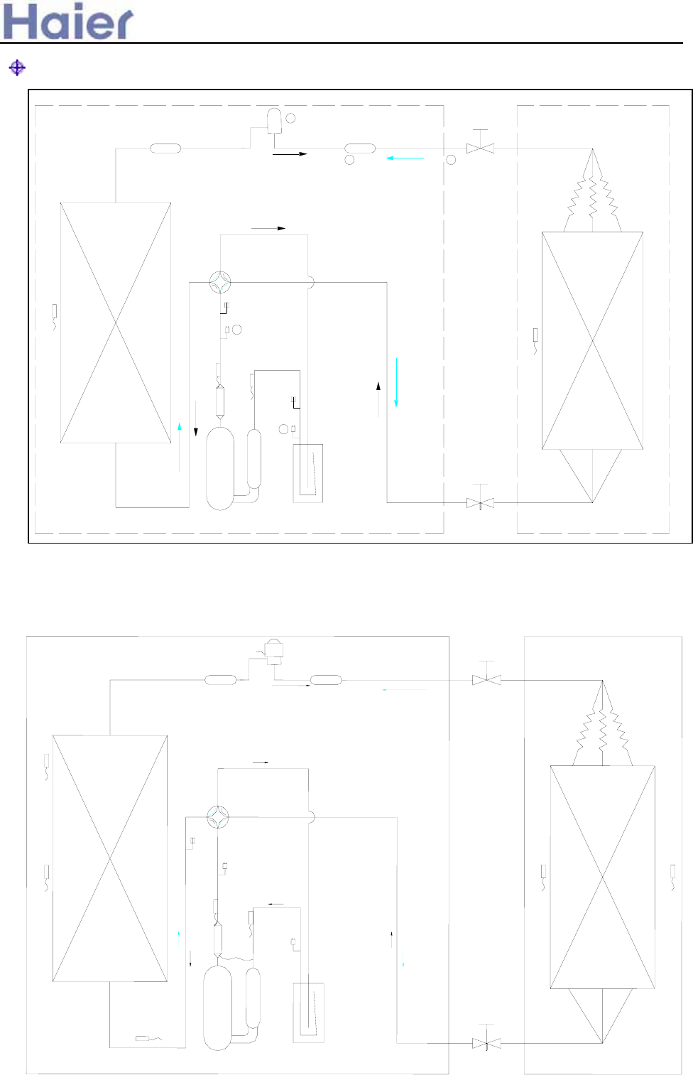
Inverter units
1. high pressure switch 2. low pressure switch 3. for AU182AFERA, is 2-way stop valve 4. for
AU182AFERA, is main capillary 5. for AU182AFERA, is sub-capillary and single check valve
for AU182AFERA, No. 1 and 2 are avaliable
3-way stop
valve (air side)
evaporator
coil
temp.
sensor
3-way stop
valve (liquid side)
filter
filter
electrical
expansion valve
air-liquid
segregator
compressor
check
valve
check
valve
condenser
defrost
temp.
sensor
cooling heating
4-way
valve
muffle
2
1
3
4
5
discharging temp.
sensor
suction temp.
sensor
>`^^WcU[S]<[c>`_V[e[`_Wc
filter
air-liquid
separator
compressor
muffle
way
valve
way stop valve
(
a
ir side)
condenser
evaporator
defrost
temp.
sensor
Te
indoor
coil
temp.
sensor
Tc
dischange
temp.
sensor
Td
suction
temp.
sensor
Ts
check
valve
filter
electrical
expansion
valve
low
pressure
switch
high pressure
switch
heating
cooling
condenser air-inlet temp.
sensor Tci
oil return capillary
outdoor
ambient
temp.
sensor
Tao
indoor
ambient
temp.
sensor
Tai
way stop valve
(liquid side)
For AU362AHERA
-63-
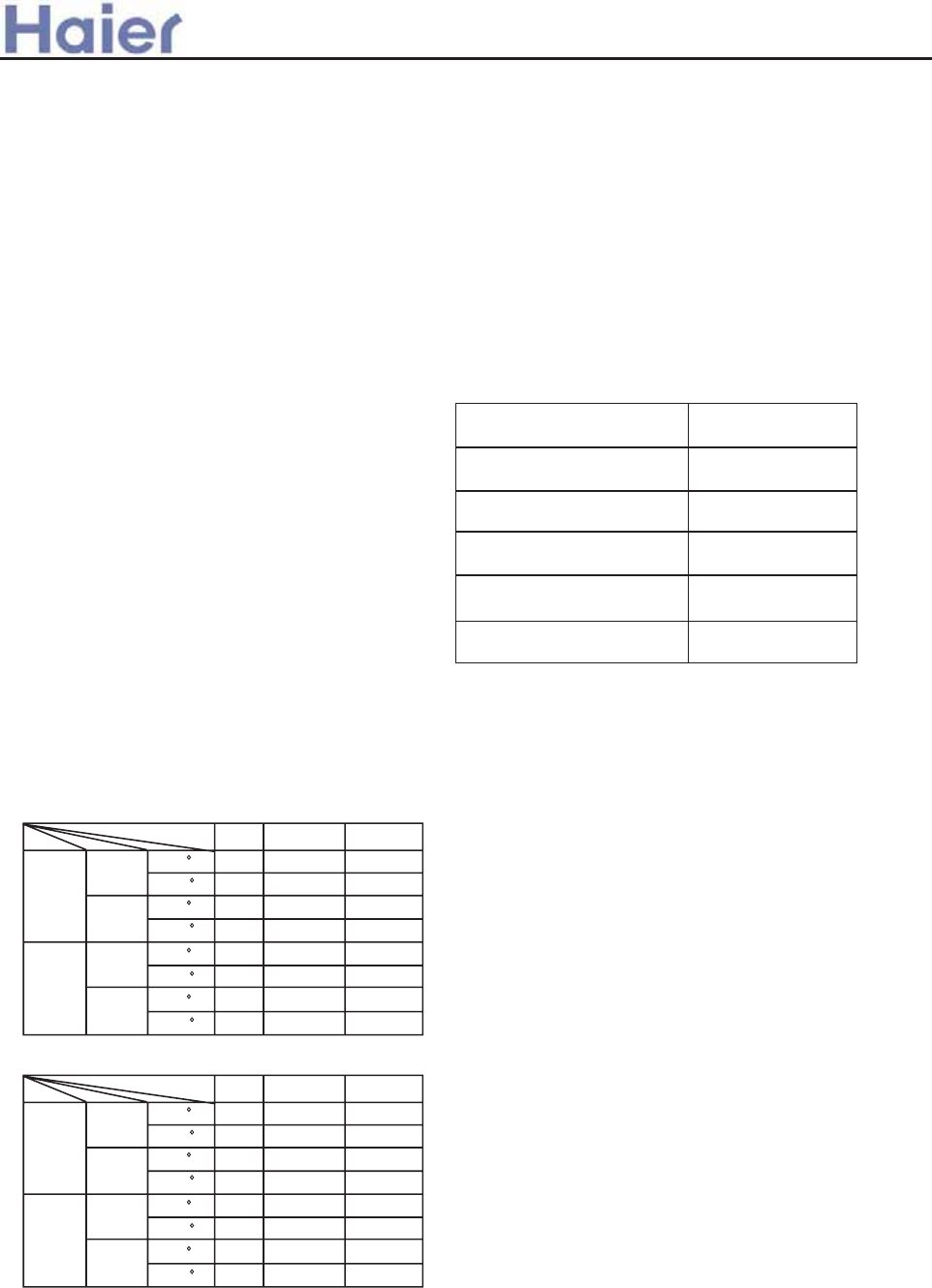
:2 T`] Zj]Yc]j g^ l`] Yaj [gf\alagf]j k`gmd\
Z] Ydd1hgd] koal[`? Yf\ l`] \aklYf[] Z]lo]]f
alk log [gflY[lk k`gmd\ Z] fg d]kk 7ee2 Sm[`
e]Yfk^gj \ak[gff][lagf emkl Z]
af[gjhgjYlagf af l`] ^ap]\ oajaf_2
;2 T`] oYkl] ZYll]jq k`Ydd Z] \akhgk]\
hjgh]jdq2
<2 T`] af\ggj mfalafklYddYlagf `]a_`lakYld]Ykl
629e2
=2 T`] Yaj Zj]Yc]j Yf\ l`] hgo]j koal[`
k`gmd\ afklYdd]\ l`] [gfn]fa]fldq j]Y[`YZd]
hd]Y[] ^gj mk]j2
Eg fgl\YeY_] Yfq hYjlk g^ l`] Yaj
[gf\alagf]j l`Yl[Yjjq j]^ja_]jYflZq
ha]j[af_ gj h]j^gjYlaf_ l`] Yaj [gf\alagf]j+k
lmZ]koal`k`Yjh gj hgafl]\ al]ek0 [jmk`af_
gj loaklaf_ Yfq lmZ]k0gjk[jYhaf_ l`]
[gYlaf_kg^^ l`] kmj^Y[]k2J^l`] j]^ja_]jYfl
khmjlk gmlYf\ _]lk aflg ]q]k0aleYq j]kmdl
af k]jagmk]q] afbmja]k2
Eg fglgZkljm[lgj [gn]j l`] n]fladYlagf
_jadd] g^ l`] Yaj [gf\alagf]j2 Eg fglhml
^af_]jkgj Yfq gl`]j l`af_kaflgl`]
afd]l3gmld]lYf\ koaf_ dgmn]j2
Eg fglYddgo [`ad\j]f lg hdYq oal`l`] Yaj
[gf\alagf]j2 Jf fg [Yk]k`gmd\ [`ad\j]f Z]
Yddgo]\ lgkalgf l`] gml\ggj mfal2
u}xwzyzwv*z|{~
T`] j]^ja_]jYlaf_ [aj[malakd]Yc1hjgg^2
52 Bhhda[YZd] YeZa]fll]eh]jYlmj] jYf_]>
5<9 ?67<=@9 =D 686BE=G9 =@ :A>>AH=@;
D=EF6E=A@
Ng\]d
62 J^ l`] kmhhdq [gj\ ak\YeY_]\0 alemkl Z]
j]hdY[]\ Zq l`] eYfm^Y[lmj]j gj alk k]jna[]
Y_]flgjYkaeadYj imYda^a]\ h]jkgf2
72 J^ l`] ^mk] gf QD ZgYj\ akZjgc]f hd]Yk]
[`Yf_] aloal`l`] lqh] g^ T 7259B 3694VBD2
82 T`] oajaf_ e]l`g\ k`gmd\ Z] af daf] oal`
l`] dg[Yd oajaf_ klYf\Yj\2
92 T`] hgo]j [YZd] Yf\ [gff][laf_ [YZd]
Yj] k]d^1hjgna\]\2 T`] j]imaj]e]flg^ l`]
hgo]j [YZd]>
I49RO1G 7H 824ee6
I4;RO1G 9H 824ee6
Dggdaf_
I]Ylaf_
Jf\ggj
gml\ggj
RYl]\ NYpaeme Nafaeme
6; 76 5<
5= 67 58
79 87 19
68 6: 11
64 6; 59
5829 11 11
;68 1;
:5< 11
EC D
WC D
EC D
WC D
Jf\ggj
gml\ggj EC D
WC D
EC D
WC D
Ggj .2FBB >
Ggj .2FRB >
Ggj k]ja]k5<6
Ggj k]ja]k686
Ggj k]ja]k8<O0 :4O
I49RO1G 7H :24ee6
Ggj k]ja]k6<60 7:6
Ggj k]ja]k6<O0 7:O
Qgo]j [YZd]
I49RO1G 7H 629ee6
I4;RO1G 9H 629ee6
T`] j]imaj]e]flg^ l`] [gff][laf_ [YZd]>
Ggj k]ja]k
4ee6/I49RO1G 5p42;9ee6? Ggj gl`]j
k]ja]kI49RO1G 8H 42;9ee62
Bdd l`] [YZd]kk`Ydd `Yn] _gll`] Fmjgh]Yf
Yml`]fla[Ylagf []jla^a[Yl]2
RYl]\ NYpaeme Nafaeme
6; 76 5<
5= 67 58
79 87 54
68 6: :
64 6; 59
5829 11 11
;68 1;
:5< 11
Dggdaf_
I]Ylaf_
Jf\ggj
gml\ggj
EC D
WC D
EC D
WC D
Jf\ggj
gml\ggj EC D
WC D
EC D
WC D
6. Installation instruction
/
>a__WcU[S^<[c>a`V[e[a`Wc
6.1 Cassette indoor unit (AB18-AB60)
I49RO1G 7H 62
AB182ACEAA
-64-
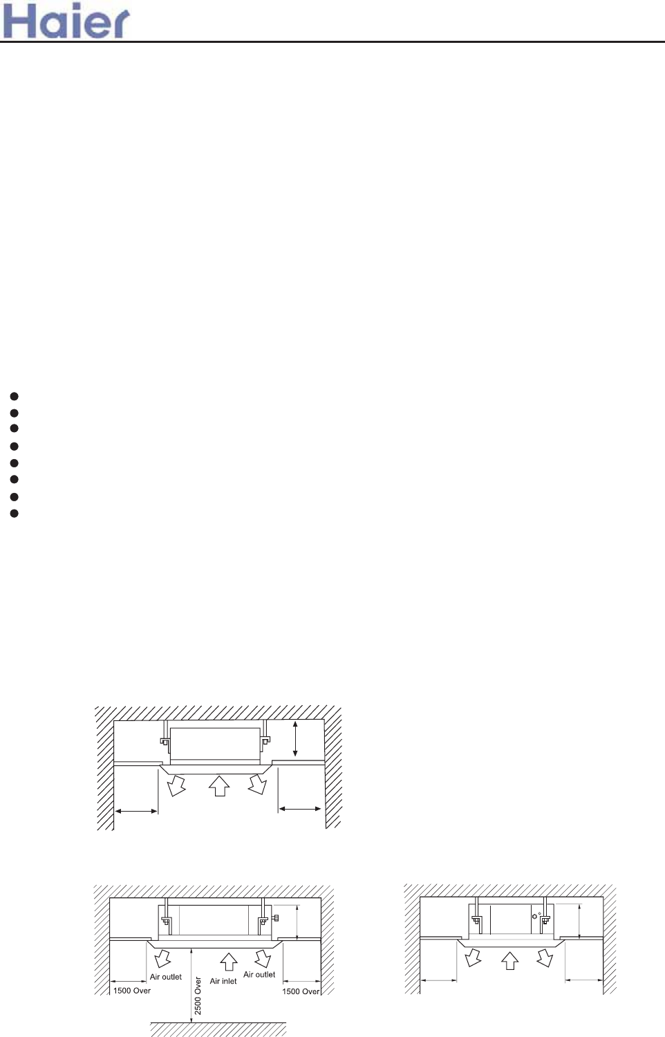
(2) Ceiling height
Indoor unit can be installed on ceiling of 2.5-3m in height. (Refer to Foeld setting and Installation Manual of
ornament panel.)
(3) Install suspending bolt. Check if the installation place is strong enough to hold weight. Take necessary
measures in case it is not safe. (Distance between holes are marked on paper pattern. Refer to paper pattern
for place need be reinforced)
Installation space
(1) Installation place shall meet the following and agreed by customers:
Place where proper air flow can be ensured.
No block to air flow.
Water drainage is smpoth.
Place strong enough to support unit weight.
Place where inclination is not evident on ceiling.
Enough space for mainenance.
Indoor and outdoor unit piping length is within limit. (Refer to Installation Manual for outdoor unit.)
Indoor and outdoor unit, power cable, inter unit cable are at least 1 m away fromT.V. radop. This is helpful
to avoid picture disturbance and noise. (Even if 1 m iskept, noise can still appear if radio wave is strong)
Selection of installation place
1500 Over 1500 Over
Air outlet
Air inlet
Air inlet
1500 1500
310
H
Air outlet Air outlet
Air inlet
260
260
1. Screw driver
2. Hacksaw
3. Drill with a diameter of 60mm
4. Inner hexagon spanner,shifting
spanner
5. Spanner (14, 17, 19,24,27mm)
6. Pipe cutter
7. Pipe expander
The installation tools listed in the following sheet can
be used as required.
8. Knife
9. Pincers
10. Leakage detector or soapy water
11. Band tape
12. Scraper
13. Refrigerant oil
>a__WcU[S^<[c>a`V[e[a`Wc
Installation tools
/
For series 182
For series 242,282,362,482,602
-65-
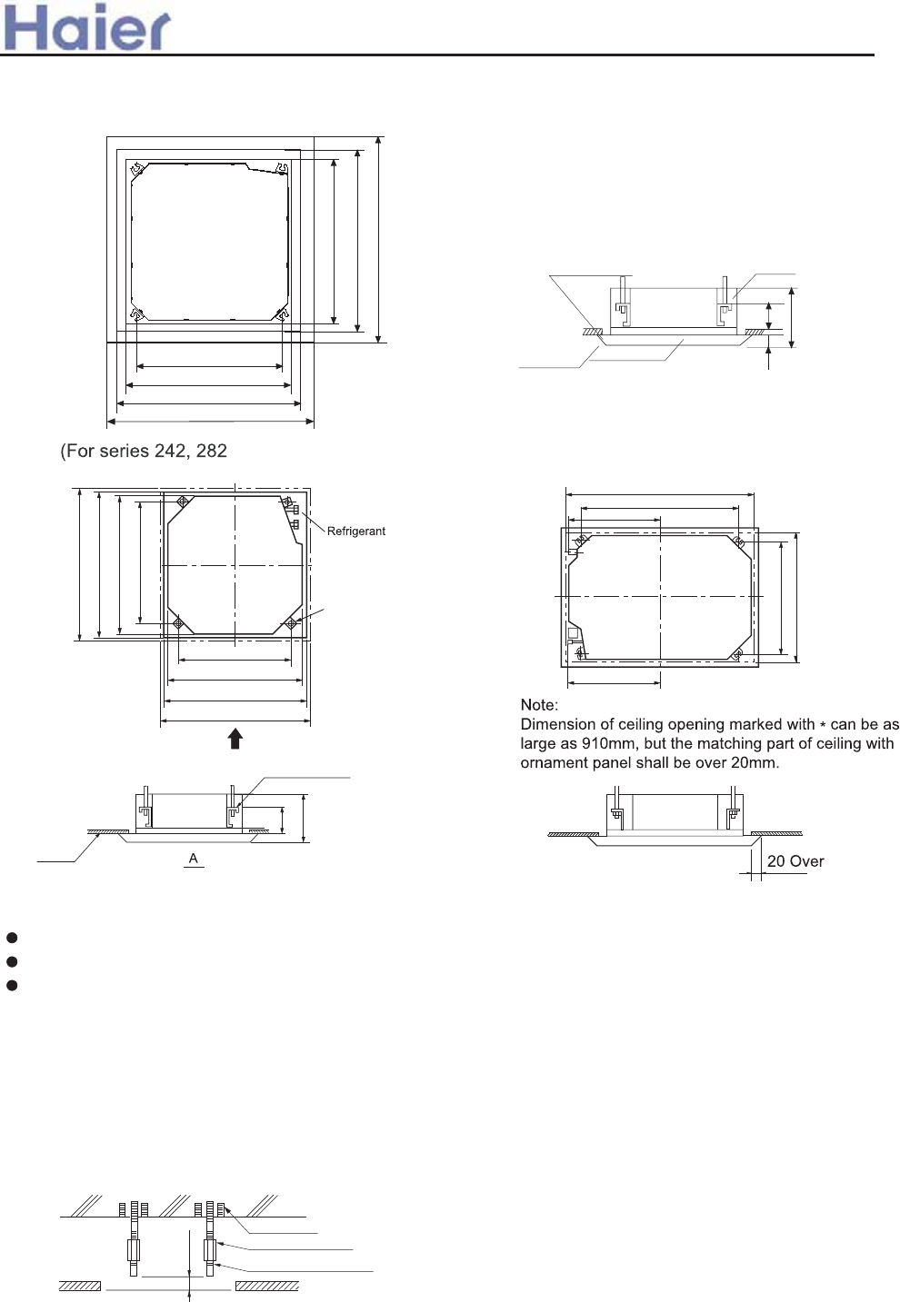
Preparation for the installtion
(1) Position of ceiling opening between unit and suspending bolt.
3
(2) Cut an opening in ceiling for installation if necessary. (when ceiling already exists.)
(3) Install a suspending bolt.
(Use a M10 bolt)
To support the unit weight, anchor bolt shall be used in the case of already exists ceiling. For new
ceiling, use built-in type bolt or parts prepared in the field.
Before going on installing adjust space between ceiling.
<Installation example>
Note: All the above mentioned parts shall be prepared in field.
Ceiling
50~100
Roof
Anchor bolt
Long nut
Suspending bolt
Refer to paper pattern for dimension of ceiling hole.
Connect all pipings (refrigerant, water drainage), wirings (inter unit cable) to indoor unit, before installation.
Cut a hole in ceiling, may be a frame should be used to ensure a smooth surface and to prevent vibration.
Contact your real estate dealer
(For series 182)
(160)
Suspending bracket
Ceiling
A
950(Ornament
890(Ceiling
840(Indoor
78
(Distance between suspending
(Distance between suspending
A
950(Ornament
890(Ceiling
840(Indoor
Suspending
1280(Ceiling opening)
(Distance between suspending
127
51
51
(Distance between suspending
860(Ceiling
78
Distance between
suspending bolts 535mm
Indoor unit 570mm
Ceiling opening 650mm
Ornament panel 700mm
Indoor unit 570mm
Ceiling opening 650mm
Ornament panel 700mm
Overlap between ceiling and
ornament panel shall be 25mm Suspending bolts
Ceiling Ornament panel
150mm
320mm
60mm
>a__WcU[S^<[c>a`V[e[a`Wc
and AB362ACEAA) and AB362ACERA
For series 482,602
-66-
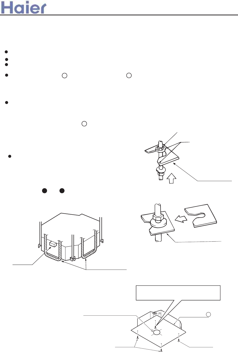
Installation of indoor unit
In the case of new ceiling
< After installation on the ceiling >
(3) Adjust unit to its right position. (Refer to preparation for the installation-(1))
(4) Check unit's horizontal level.
Watert pump and flating switch is installed inside indoor unit, check four corners of the unit for its level
using horizontal compartor or PVC tube with water. (If unit is tilting against the direction of water drainage,
problem may occur on floating switch, causing water leakage.)
(5) Remove the washer mounlting , and tighten the nut above.
(6) Remove the paper pattern.
(2) As for the dimensions of ceiling hole, see paper pattern. Ask your real estate dealer for details.
Center of the hole is marked on the paper pattern.
Center of the unit is marked on the card in the unit and on the paper pattern.
Mount paper pattern onto unit using 3 screws . Fix the corner of the drain pan at piping outlet.
(1) Install unit temporally
Put suspending bracket on the suspending bolt. Be sure to use nut and washer at both ends of the bracket.
In the case of ceiling already exists
Screws at the piping outlet is fixed at
the corner of drain pan.
Center of ceiling hole Paper pattern 5
Paper pattern
Screw (accessory)
Screw (accessory)
[Fix the paper pattern]
(1) Install unit temporally
Put suspending bracket on the suspending bolt.
Be sure to use nut and washer at both ends
of the bracket. Fix the bracket firmly.
(2) Adjust the height and position of the unit.
(Refer to preparation for the installation (1) ).
(3) Proceed with and of "In the case of new ceiling".
4
Nut (Prepare in feild)
Washer (Prepared in feild)
Suspending bolts
Fasten (double nuts)
Insert
Washer fixing pad
(prepared in feild)
[ secure the washer firmly]
Level
Polythene pipe
3 4
2
56
>a__WcU[S^<[c>a`V[e[a`Wc
-67-
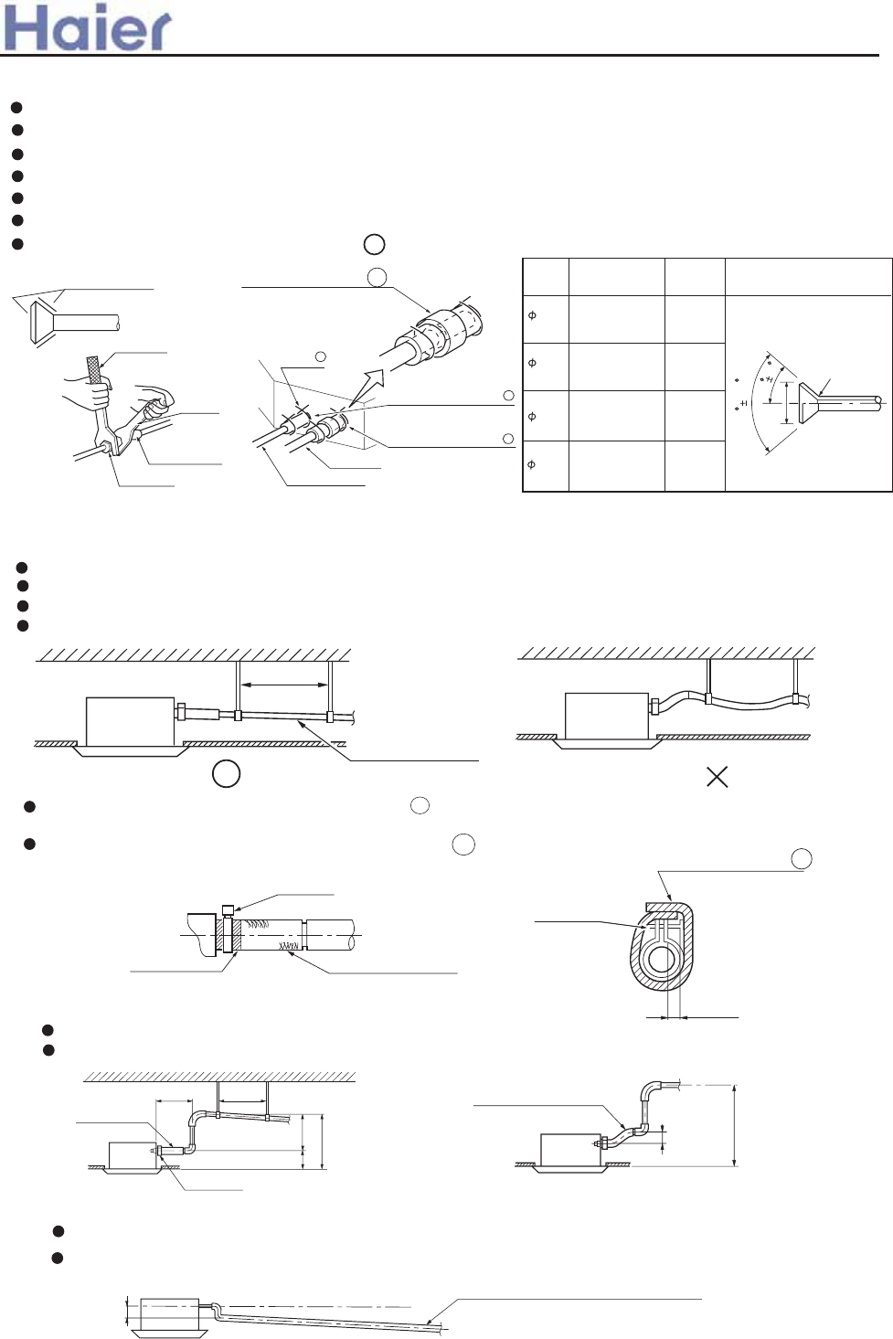
Installation of water drainage pipe
(As for outdoor piping, please refer to installation Manual of outdoor unit.)
Refrigerant piping
Outdoor is precharged with refrigerant.
Be sure to see the Fig.1, when connecting and removing piping from unit.
For the size of the flare nut, please refer to Table 1.
Apply refrigerant oil at both inside and outsid of lflare nut. Tighten it band tight 3-4 turns then tighten it.
Use torque specified in Table 1. (Too much force may damage flare nut, causing gas leakage).
Check piping joints for gas leakage. Insulate piping as shown in Fig. below.
Cover joint of gas piping and insulator with seal.
Table 1
(1) Install water drainage pipe
Pipe dia, shall be equal or larger than that of unit piping.(pipe of polyethylent; size: 25mm; O.D:32mm)
Drain pipe should be short, with a downward slope at least 1/100 to prevent air bag from happening.
If downward slope can't be made, take other measures to lift it up.
Keep a distance of 1-1.5m between suspending brackets, to make water hose straight.
Slope over 1/100
1-1.5m
(Note)
If several water hoses join together, do as per following proceedures.
Specifieations of the water hoses shall meet the requirements for the unit running.
The slope of water drain hose (1) shall be within 75mm, don't apply too much force on it.
Medium size seal pad 11 (accessory)
R0.4 ~ 0.8
A
90 0.5
45
2
Connect water hoses with a T joint.
Use the self-provided stiff pipe and clamp with unit. Insert water pipe into water plug until it reaches
the white tape. Tighten the clip until head of the screw is less than 4mm from hose.
Wind the drain hose to the clip using seal pad 9 .
Insulate drain hose in the room.
1
Apple refrigerant oil
Torque spanner
spanner
Piping joing
Flare nut
Clamp 3
Gas pipe
Liquid pipe
Insulator (accessory)
(For liquid pipe)
Insulator (accessory)
(For gas pipe)
(Cover the piping joint
with seal pad.)
Pipe
size Tighten
torque A(mm) Flare shape
9.52 3270~3990N.cm
(333~407kgf.cm)
6180~7540N.cm
(630~770kgf.cm)
15.88
19.05
9720~11860N.cm
(990~1210kgf.cm)
12.0~12.4
18.6~19.0
22.9~23.3
7
8
7
<Cautions for the drain water lifting pipe>
75 below
Self-provided stiff pipe
(accessory)
500 below
Clamp
Tape (White) Self-provided stiff pipe
300mm below 1~1.5m
280 below
500 below
220
Drain hose
(accessory) drain water lifting pipe
Suspending bracket
Clamp
(accessory)
Installation height shall be less than 280mm.
There should be a right angle with unit, 300mm from unit.
Over 100
4mm below
(accessory)
(accessory)
Large size seal pad
Clamp
10
6.35 1420~1720N.cm
(144~176kgf.cm) 8.3~8.7
>a__WcU[S^<[c>a`V[e[a`Wc
-68-
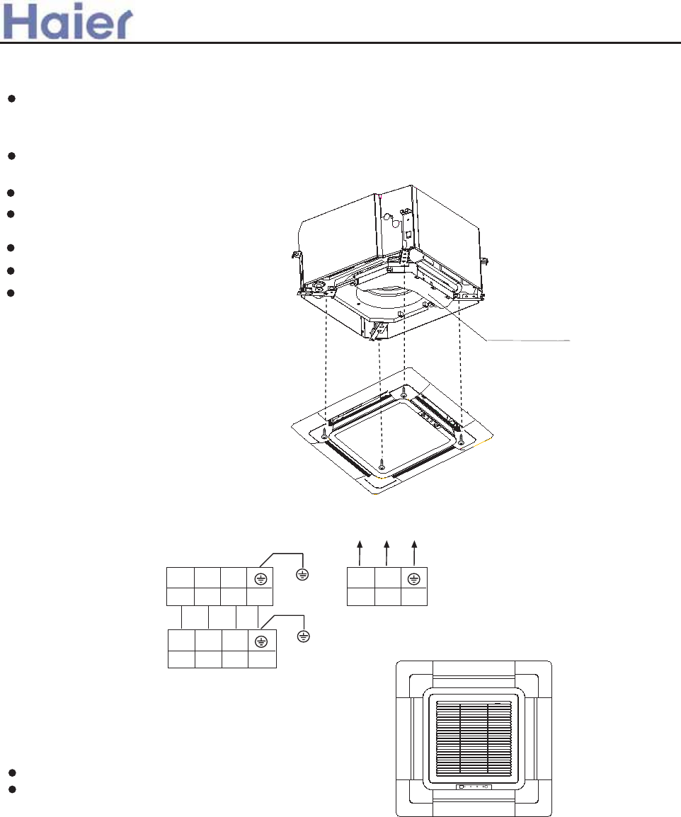
>a__WcU[S^<[c>a`V[e[a`Wc
>YVT[ fYVcYVa Z^U__a d^Zc Zb Y_aZi_^cR\ fZcY \VeV\Va _a `_\hcYV^V `Z`V WZ\\VU fZcY fRcVa - R^U
TYVT[ cYRc cYV UZ]V^bZ_^ _W cYV TVZ\Z^X _`V^Z^X Zb T_aaVTc/ MR[V _WW cYV \VeVa XRdXV SVW_aV Z^bcR\\
cYV _a^R]V^c `R^V\/
ARbcV^ cYV bTaVfb c_ ]R[V cYV YVZXYc UZWWVaV^TV SVcfVV^ cYV cf_ bZUVb _W Z^U__a d^Zc \Vbb
cYR^ 6]]/
AZabc WZg Zc fZcY bTaVfb cV]`_aR\\h/
ARbcV^ cYV cf_ cV]`_aR\\h WZgZ^X bTaVfb
R^U _cYVa cf_- R^U cZXYcV^ cYV W_da bTaVfb/
>_^^VTc cYV fZaVb _W bh^TYa_.]_c_a/
>_^^VTc cYV fZaV _W bZX^R\/
DW ^_ aVb`_^bV _W aV]_cV T_^ca_\\Va-
TYVT[ fYVcYVa cYV fZaZ^X Zb T_aaVTc-
aVbcRac aV]_cV T_^ca_\\Va 21 bVT_^Ub
RWcVa bYdc _WW `_fVa bd``\h/
:FZ]Zcb _W `R^V\ S_RaU Z^bcR\\RcZ_^;
D^bcR\\ cYV `R^V\ S_RaU Z^ cYV UZaVTcZ_^ bY_f^ Z^ cYV
WZXdaV/ MYV Z^T_aaVTc UZaVTcZ_^ fZ\\ aVbd\c Z^ fRcVa
\VR[RXV- ]VR^fYZ\V bfZ^X R^U bZX^R\ aVTVZeZ^X RaV
UZb`\RhVU cYRc TR^^_c SV T_^^VTcVU/
A_a bVaZVb 283
A_a <=283<>@<<
JIP@K LNJJFQ9 2JC-331.341Oj-61Ci
234 FH
2 3 4
DH?IIK NHDM
M@KGDH<F =FI>E
INM?IIK NHDM
M@KGDH<F =FI>E
@\VTcaZT T_^ca_\ S_g
Q0B
Q0B
-69-
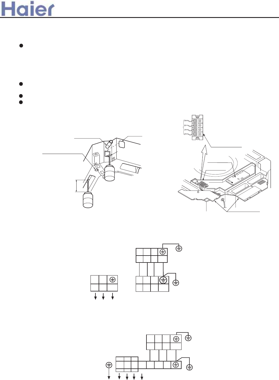
(2) Check if water drainage is smooth after installation.
Charge, through air outlet or inspecting hole, 1200ccd water to see water drainage.
After wiring
Remove cover of control box, connect 1PH power to terminal 1 and 2 on terminal block.,use remote
controller to operate the unit.
Note, in this operation, fan will be running.
Upon confirmation of a smooth water drainage, be sure to cut off power supply.
Check water drainage in cooling operation.
Method of water charging
Charge water from
air outlet
Charge water from
inspecting hole
Watering can of plastic
pipe should be about
100 mm long
100mm
Water drainage port for
maintenance
(Drain water from
this hole)
Self-provided stiff pipe Maintenance
Inspecting hole
1 2 3 D
When wiring is not complete
Cover of controll box
PCB on
indoor unit
Terminal block
Connect with
outdoor unit
Terminal block
>a__WcU[S^<[c>a`V[e[a`Wc
For series 242, 282, 362, 482, 602
INM?IIK NHDM
M@KGDH<F =FI>E
DH?IIK NHDM
M@KGDH<F =FI>E
JIP@K LNJJFQ9
481.511O-4Hj-61Ci
KL M H234
234
Q0B
Q0B
Q0B
234
2JC-331.341Oj-61Ci
JIP@KLNJJFQ9
DH?IIK NHDM
M@KGDH<F =FI>E
FH
234
Q0B
+A_a bVaZVb 473- 583- 713 ,
+A_a bVaZVb 353- 383-473 R^U <=283<>@K< ,
-70-
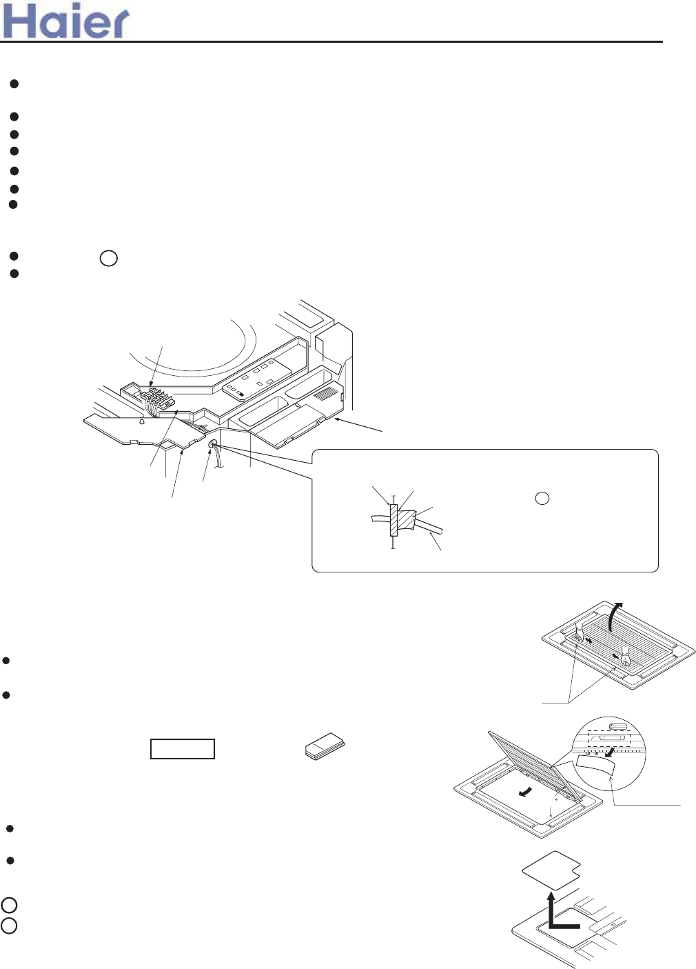
Inatallation of ornament panel
1. Prepare ornament panel Handling of ornament panel
Ornament panel shall not be placed face down or against wall,
neither on an uneven object.
Don' t bend carelessly the swing flap, or, problem may occur.
(1)
Remove air inlet grill from ornament panel *
Push in the bar on inlet grill and lift it up. (Refer to Fig. 1)
Lift it up for about 45 degree and remove it from ornament. Tear off adhesive
tape fixing air filter on the back of the air inlet grill. (Refer to Fig. 2)
Be sure to show customers Operation Manual and guide them how to operate unit
correctly. Before installation. read also the Installation Manual of indoor unit.
With this ornament , 2 or 3 air flow direction is not available.
Suitable height is 3 m.
2
(2)
Remove cover plate at corner
Tear off the adhesive tape, and slide it off. (Refer to Fig. 3)
Cautions for the installation
Accessory
Pad
Bar Fig. 1
Wiring
All supplied parts. materials and wiring operation must in appliance with
local code and regulations.
Use copper wire only.
When make wiring, please refer to wiring diagram also.
All wiring work must be done by qualified electricians.
A circuit breaker must be installed, which can cut power supply to all system.
See Installation Manual of outdoor unit for specifications of wires, circuit breaker, switches and wiring etc.
Connecting of unit
Remove cover of switch box (1) , drag wires into rubber tube A, then, after proper wiring with other wires,
tighten clamp A. Connect wires of correct pole to the terminal block inside.
Wind seal 12 around wires. (Be sure to do that, or, dew may occur).
Upon connecting, replace control box cover (1) and (2).
Pad
45
Fig. 2
Adbesive tape
Terminal block
Cover of control box(1)
Rubber tube A
Grounding lead
Cover of control box(2)
1
Slide
Fig. 3
>a__WcU[S^<[c>a`V[e[a`Wc
jxw
is
Heah` senejc
Cpp]_d oa]h l]`
Fkj-p b]eh pk oa]h ep1 kn s]pan i]u _kia ej3
Sq^^an pq^a Okpa? J]ra ep oa]ha`1 ha]rejc jk ol]_a3
Ta]h l]` .oi]hh oeva /
.Xej` ]nkqj` sena/
^_
-71-
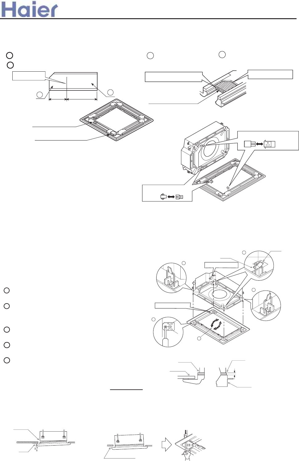
(1)
3. Install ornament panel on indoor unit.
As shown in Fig . 7, match the position of swing
flap motor with that of the indoor unit piping hole ,
so that ormament panel can be placed on to indoor
unit.
Installation of ornament panel
Place the holding ring on swing flao motor side
teporarily on hooks of the indoor unit. (2 pcs)
Put the other two holding rings on the hooks at
both
side of the indoor unit. (Care should be taken not to
push wiring of swing flap motor into seals).
Screw in all 4 screws under holding ring for about
15mm. (Pancl will rise).
Adjust the ornament panel as per Fig. 7 to cover
opening on the ceiling.
Tighten screws to redrce the thickness of seals
between ornament and indoor unit to 5-8mm.
If indoor unit is at horizontal level and water
drainage is smooth, then, indoor unit height
can be adjusted throrgh holes at corners of
ornament panel.
If screws are not tighten tight,
problems in Fig, 8 might occur.
Tighten screws properly.
If there are still space
after tightening of screws,
please readjust the height
of indoor unit.
(Refer to Fig. 9)
Leave no space. Fig. 9
Gas leakage.
Gas leakage
from roof.
Contamination Mist exists and drop down.
Fig. 8
For indoor unit installation, please
refer to Installation Manual.
(2)
1
2
3
4
5
5 _ 8mm
3
2
2
1
4
Holding ring
Piping hole position
Swing flap motor
Fig. 7
Seal
Indoor unit
Ceiling material
Ornament panel
Hook
Caution
2. Mounting on high ceiling
(1) Ornament panel can be mounted on ceiling as high as 3 m.
(2) Please install pad as accessary.
Cut open the pad along cutting ling. Use part a only and discard part b . (Refer to Fig. 4)
Install part a of the pad on the place shown in Fig. 5. Refer to Fig. 6.
(3)Wiring on ornament panel
Connecting of wiring of the swing
flap motor on ornament panel. (2 places)
(Refer to Fit . 10)
If connecting is not made, error code
(A7) appears on remote controller. So,
make proper connecting.
Side of ornament panel
Fig. 10
Wiring diagram
Side of indoor unit
Fig. 4
50
Cutting line
100
ab
Place it on the frame.
Part a of the pad
Leave no space
Fig. 6
Part a of the pad
Swing flap motor
Fig. 5
1
2
>a__WcU[S^<[c>a`V[e[a`Wc
-72-
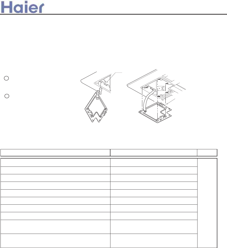
Item to the checked
Pay special care to the following and check after installation
Unproper installation may cause Check
Is indoor unit firmly installed?
Is gas leakage check performed?
Is unit properly insulated?
Is water drainage smooth?
Is power voltage meet that stipulated on the nameplate?
Is wiring and piping correctly arranged?
Is unit safely grounded?
Is wire size correct?
Are there any obstacles on air inlet and outlet grill of
indoor and outdoor unit?
Is record made for piping length and refrigerant
charging amount?
Unit might fall down, make vibration or noise.
This may lead to gas shortage.
Dew or water drop may occur.
Dew or water drop may occur.
Problem may occur or parts got burned.
Problem may occur or parts got burned.
There might be a danger of electric shock.
Problem may occur or parts got burned.
This may cause poor cooling.
It is hard to control refrigerant charging
amount.
4. Installation of inlet grill and cover plate
Installation of inlet grill
Install in reversed order of "Prepare ornament pandl".
Inlet grill can be adjusted into four directions by turning inlet grill. Inlet grill position can be adjusted as
per customers request.
(1)
Install cover plate on the corner
As shown in Fig. 11 tie the
cover plate onto the bolt on
ornament plate.
Install cover plate onto
ornament plate.
(Refer to Fig. 12)
(2)
When installing inlet grill, take care not to twist wiring of swing flap motor.
2
1
Slide all five hold rings
to let them drop in holes
on ornament plate,
Fig. 12
Fig. 11
>a__WcU[S^<[c>a`V[e[a`Wc
-73-
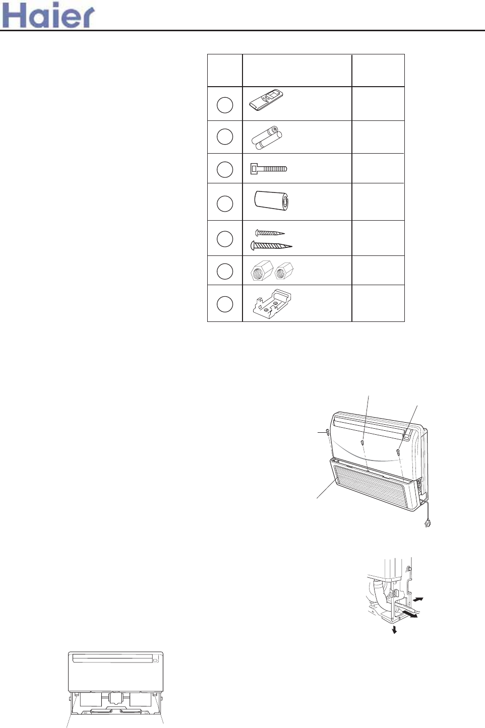
Standard accessories:
The following installation parts are furnished.
Use them as required.
INSTALLATION PROCEDURE
PREPARING INDOOR UNIT INSTALLATION
1. REMOVE THE INTAKE GRILL
Install the room air conditioner as follows:
Open the intake grill and remove the
three or four or six screws.(Fig. 1)
When the directions are selected, drill a 7 cm dia. hole on the wall so
that the hole is tilted downward toward the outdoor for smooth water
flow. When the pipe is led out from the rear, make a hole in Fig.6, at
the position shown.
(Fig.3)
Drain hose (Left side) Drain hose (Right side)
Remark: The main unit can be wired before
the indoor unit is installed. Select
the most appropriate installation
order.
A. FLOOR CONSOLE TYPE
1. DRILLING FOR PIPING
Select piping and drain directions.(Fig.2) (Series14,18,24)
The piping and drain can be made in three directions as shown below.
down
Pipe connection requirement
Please refer to the specification to confirm the stop valve diameter and the permitted pipe drop and pipe length.
(Fig. 1)
Machine screw
Tapping screw
Tapping screw
Intake grill
(Fig. 2)
rear
right
1
2
3
4
5
1
2
4
1+1
2+2
No. Accessory parts Qty.
Remote controller
Battery
Wire clamp
Heat
insulation
sheathing
Screw
Screw cap
Remote
controller
bracket
6
71
1+1
>a__WcU[S^<[c>a`V[e[a`Wc
6.2 Convertible indoor unit (AC18-AC24)
-74-
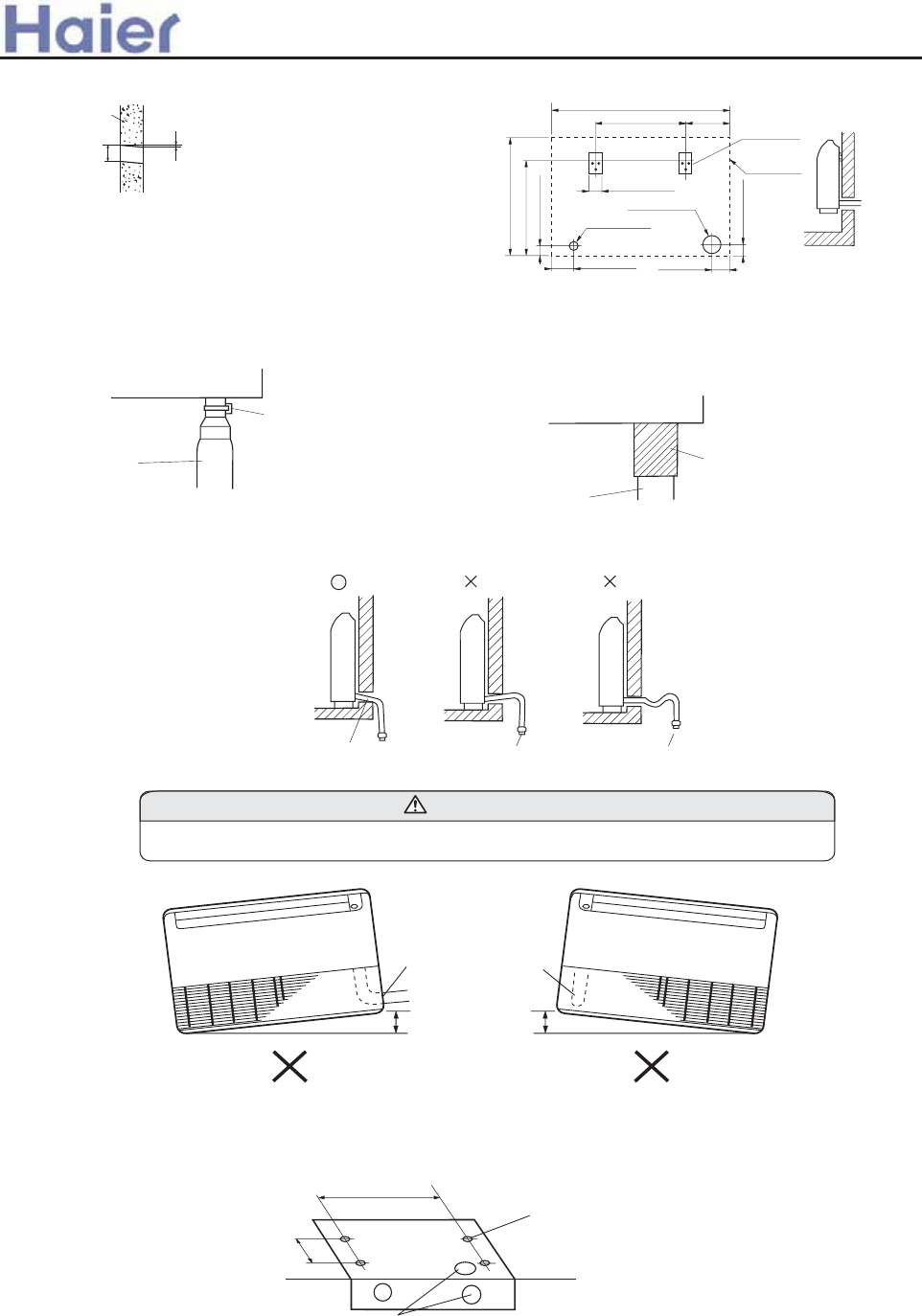
drain hose with a nylon fastener. (Fig.6)
2. INSTALLING DRAIN HOSE
Be sure to arrange the drain hose correctly so that it is leveled lower than the drain hose connecting port of the indoor unit.
Do not install the unit drain hose side is too high. Height A should be less than 5 mm.(Fig.9)
Wrap the insulation (drain hose) around the drain hose connection.(Fig.7)
Arrange the drain hose
lower than this portion.
(Fig. 8) OK NO NO
Drain hose
CAUTION
Wall
10cm
6mm
Indoor unit outdoor unit
(Fig. 4)
For series 14,18,24 when installing set to wall, install
the accessory wall bracket at the position shown in
Fig.5,and mount the set to it.
(Fig. 5)
Wall bracket
Side of set
65.5cm
99cm
50cm 24.5cm
6.5cm
12.5cm 10cm
6.5cm
53cm
4.5cm
7cm hole
3.5cm hole
Drain pan
Drain hose
Nylon fastener
(Fig. 6) (Fig. 7)
Drain pan
Drain hose
Insulation
(Drain hose)
Drain hose
(Fig. 9)
A
Drain hose
A
B. UNDER CEILING TYPE
Using the installation template, drill holes for piping and anchor bolts(for holes).(Fig.10)
(Fig. 10)
Installation
template
Wall
Ceilling
Drilling position
for piping
Drilling position
for anchor bolt
For series 18,24
200mm
900mm
>a__WcU[S^<[c>a`V[e[a`Wc
-75-
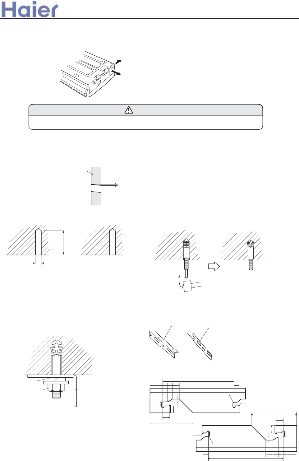
Select piping and drain directions. (Fig.11)
1. DRILLING FOR PIPING
(Fig. 11)
Rear (Install the drain hose
in the direction.)
Right
(Fig. 12)
Insert the anchor bolts into the drilled holes, and drive the pins
completely into the anchor bolts with a hammer. (Fig. 13)
2. DRILLING HOLES FOR ANCHOR BOLTS AND INSTALLING THE ANCHOR BOLTS
When the directions are selected, drill 80mm and 50mm or 150mm dia. hole on the wall so that the hole is tilted
downward toward the outdoor for smooth water flow.
With a concrete drill, drill four 12.7 mm dia. Holes.(Fig.12)
Wall
6mm
60 to 70mm
12.7mm
(Fig. 13)
Install the drain hose at the rear; it should not be installed on the top or right side.
CAUTION
3. INSTALLING BRACKETS
(Fig. 14)
Install the brackets with nuts, washers and spring washers.(Fig. 14)
4. INSTALLING INDOOR UNIT
Reset the hex bolts as shown in Fig.15.
68 16 21 28
381
232
26.5
26.5
2-R2.5
10
18
7.5
4-R5
68
16
21
28
381
232
26.5
26.5
2-R2.5
10
18
7.5
4-R5
Bracket (Right)
Bracket (Left)
For series 14,18,24
Spring washer
Special nut Bracket
>a__WcU[S^<[c>a`V[e[a`Wc
-76-
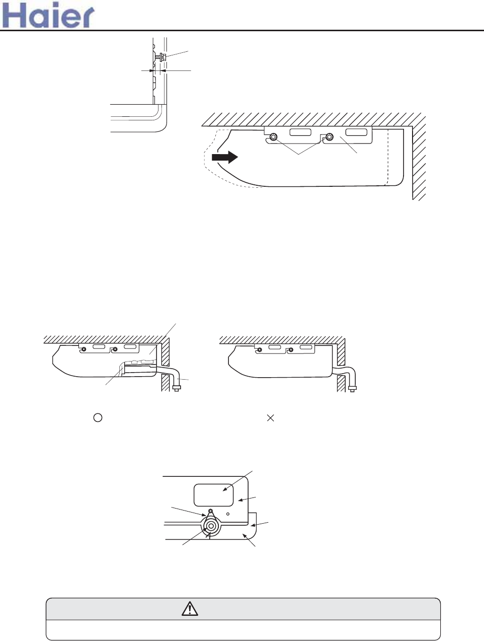
Hex bolt
8 to 13mm
Indoor unit
(Fig. 15)
Apply the indoor unit to the brackets.(Fig.16)
Now, securely tighten the hex bolts in both sides.
(Fig. 16)
Bolt Bracket
Indoor unit
5. INSTALL THE DRAIN HOSE
Select whether the drain hose will be connected to the left or right side.(Fig.3)
Insert the drain hose into the drain pan, then secure the drain hose with a nylon fastener.(Fig.6)
Wrap the insulation (drain hose)around the drain hose connection.(Fig.7)
Be sure to arrange the drain hose correctly so that it is leveled lower than the drain hose connecting port of the
indoor unit.(Fig.8)
When drain hose is arranged backward. Secure the drain hose with the VT wire. (Fig. 18)
(Fig. 18)
Piping hole
Base (Bottom)
Intake grill
VT wire hole
Pass the drain hose through here
For series 14,18,24
Cut the grill
(Fig. 17)
OK
Remove the hole cover.
Arrange the drain hose
lower than this portion
Drain hose
NO
GAS LEAKAGE INSPECTION
After connecting the piping, check the joints for gas leakage with leakage detector.
CAUTION
HOW TO CONNECT WIRING TO THE TERMINALS
A. For solid core wiring (or F-cable)(Fig.19A)
(1) Cut the wire with a wire cutter or wire-cutting pliers, then strip the insulation to about 25mm of the exposed solid
wire.
(2) Using a screwdriver, remove the terminal screw(s) on the terminal board.
(3) Using pliers, bend the solid wire to form a loop suitable for the terminal screw.
(4) Shape the loop wire properly, place it on the terminal board and tighten securely with the terminal screw using
a screw driver.
>a__WcU[S^<[c>a`V[e[a`Wc
-77-
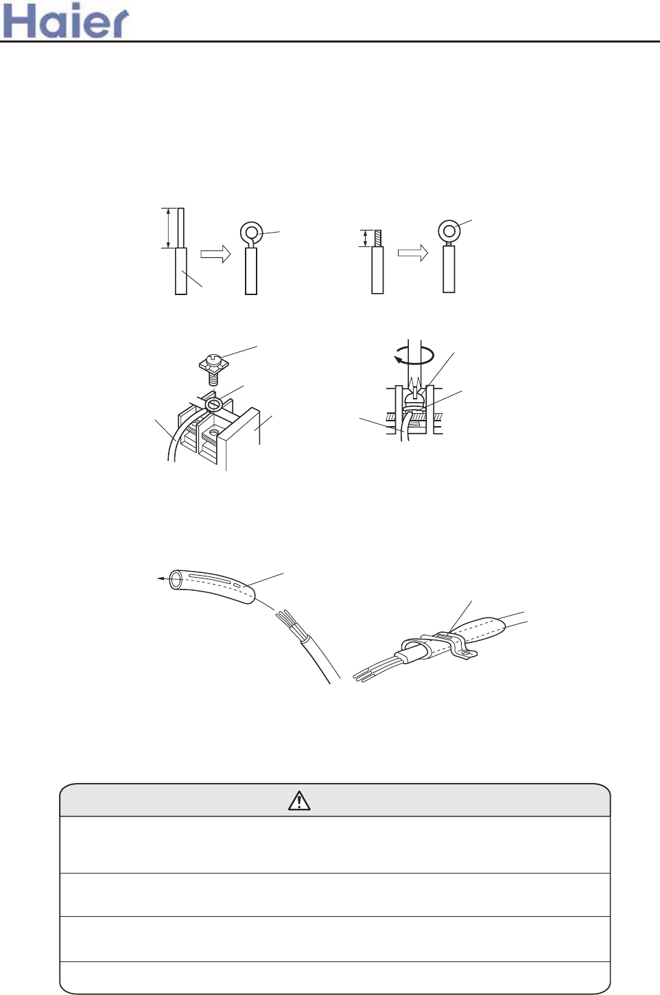
B. For strand wiring(Fig.19B)
(1) Cut the wire with a wire cutter or wire-cutting pliers, then strip the insulation to about 10mm of the exposed strand wiring.
(2) Using a screwdriver, remove the terminal screw(s)on the terminal board.
(3) Using a round terminal fastener or pliers, securely clamp a round terminal to each stripped wire end.
(4) Position the round terminal wire, and replace and tighten the terminal screw using a screw driver.
After passing the connection cord and power cable through the insulation tube, fasten it with the cord clamp, as
shown in Fig.20
HOW TO FIXED CONNECTION CORD AND POWER CABLE AT THE CORD CLAMP
(Fig. 19)
Insulation
Strip 25mm
Loop
Strip 10mm
Round
terminal
A. Solid wire B. Strand wire
Screw with
special washer
Round
terminal
Wire
Terminal
board
Screw with
special washer
Round
terminal
Wire
(Fig. 20) Insulation tube
Cord clamp
Use VW-1, 0.5 to 1.0 mm thick, PVC tube as the insulation tube.
ELECTRICAL WIRING
CAUTION
(1) Match the terminal block numbers and connection cord colors with those of the
outdoor unit.
Erroneous wiring may cause burning of the electric parts.
(2) Connect the connection cords firmly to the terminal block. Imperfect installation
may cause a fire.
(3) Always fasten the outside covering of the connection cord with the cord clamp.
(If the insulator is chafed, electric leakage may occur.)
(4) Always connect the ground wire.
>a__WcU[S^<[c>a`V[e[a`Wc
-78-
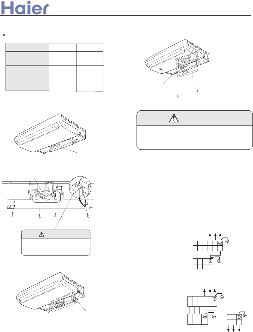
ELECTRICAL REQUIREMENT
Electric wire size and fuse capacity:
1. INDOOR UNIT SIDE
(1) Remove the electric component box.
(3) Remove the electric component box cover.
Fig. 24
Base
Electric component box cover
Remove the three tapping screws.
(1) Remove the cord clamp.
(2) Process the end of the connection cords to the
dimensions shown in Fig.34.
(3) Connect the end of the connection cord fully into the
terminal block.
(4) Wiring
(4) Fasten the connection cord with a cord clamp.
(5) Fasten the end of the connection cord with the
screw.
CAUTION
Be careful not to pinch the lead wires
between the electric component box
and base.
Power supply
cord (mm
2
)
Fuse capacity(A)
2.5
30
Connection cord
(mm
2
)
Type
0.75
Fig. 21
Electric component box
Fig. 22
Electric component box
Remove the four tapping
screws.
CAUTION
Do not remove the screws. If the screws
are removed, the electric component
box will fall.
0.75
4.0
40
For series 182 For series 242
(2) Pull out the electric component box.
Fig.23
Electric component box
>a__WcU[S^<[c>a`V[e[a`Wc
FH
J_fVa bd``\h92JC- 331.341Oj- 61Ci
234HF
234
<>283<>@<<
<>283<>@K< <>353<>@<< <>353<>@K<
Q0B
Q0B
J_fVa bd``\h92JC- 331.341Oj- 61Ci
234HF
234
Q0B
Q0B Q0B
INM?IIK NHDM
M@KGDH<F=FI>E
DH?IIK NHDM
M@KGDH<F=FI>E
DH?IIK NHDM
M@KGDH<F=FI>E
INM?IIK NHDM
M@KGDH<F=FI>E
-79-
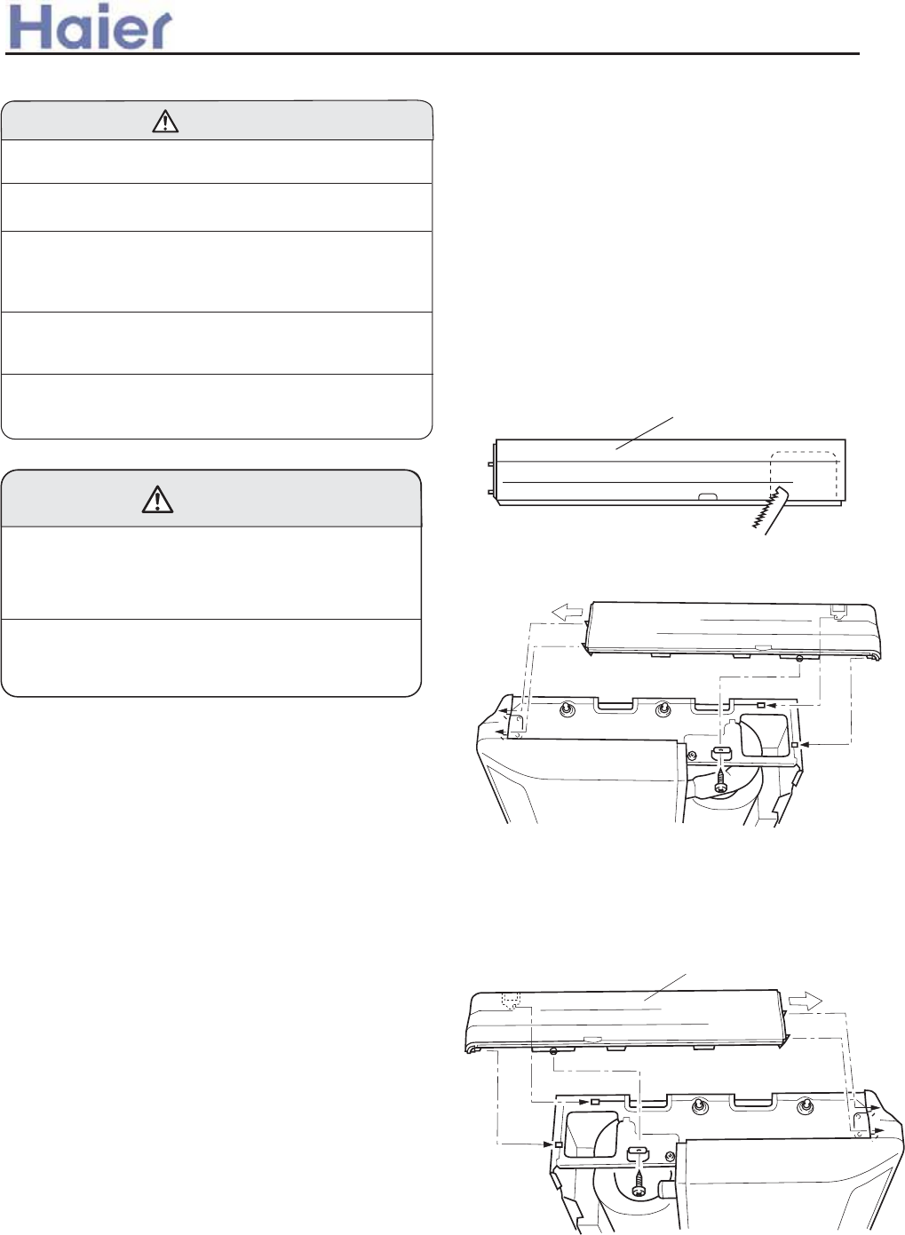
ELECTRICAL WIRING
(1) The power source capacity must be the sum of the
room air conditioner current and the current of other
electrical appliances. When the current contracted
capacity is insufficient, change the contracted capacity.
(2) When the voltage is too low and the air conditioner is
difficult to start, contact the power company the voltage
raised.
CAUTION
TEST RUNNING
1. CHECK ITEMS
(1) INDOOR UNIT
(1) Is operation of each button on the remote control
unit normal?
(2) Does each lamp light normally?
(3) Do not air flow direction louvers operate normally?
(4) Is the drain normal?
(2) OUTDOOR UNIT
(1) Is there any abnormal noise and vibration during
operation?
(2) Will noise, wind, or drain water from the unit disturb
the neighbors?
(3) Is there any gas leakage?
CUSTOMER GUIDANCE
Explain the following to the customer in accordance
with the operating manual:
(2) Air filter removal and cleaning, and how to use
air louvers.
(3) Give the operating and installation manuals to
the customer.
(1) Always use a special branch circuit and install a special
receptacle to supply power to the room air conditioner.
(2) Use a circuit breaker and receptacle matched to the
capacity of the room air conditioner.
(3) The circuit breaker is installed in the permanent wiring.
Always use a circuit that can trip all the poles of the
wiring and has an isolation distance of at least 3mm
between the contacts of each pole.
(4) Perform wiring work in accordance with standards so
that the room air conditioner can be operated safely
and positively.
(5) Install a leakage circuit breaker in accordance with the
related laws and regulations and electric company
standards.
WARNING
(1) Starting and stopping method, operation switching,
temperature adjustment, timer, air flow switching,
and other remote control unit operations.
MOUNT THE COVER PLATE AND
THE INTAKE GRILL
1.Mount the cover plate. (Right)
(1) Cut a pipe exit hole in the right plate. This is
only when the pipe exits from the right side.
(This operation is not required when the
protrusion is on the top or rear.)
Fig. 25 Cover plate (Right)
(2) Join the cover plates (right) and mount with screws.
Fig. 26
(1) Join the cover plate (left) and mount with screws.
Fig. 27
2. Mount the cover plate.(Left)
>a__WcU[S^<[c>a`V[e[a`Wc
-80-
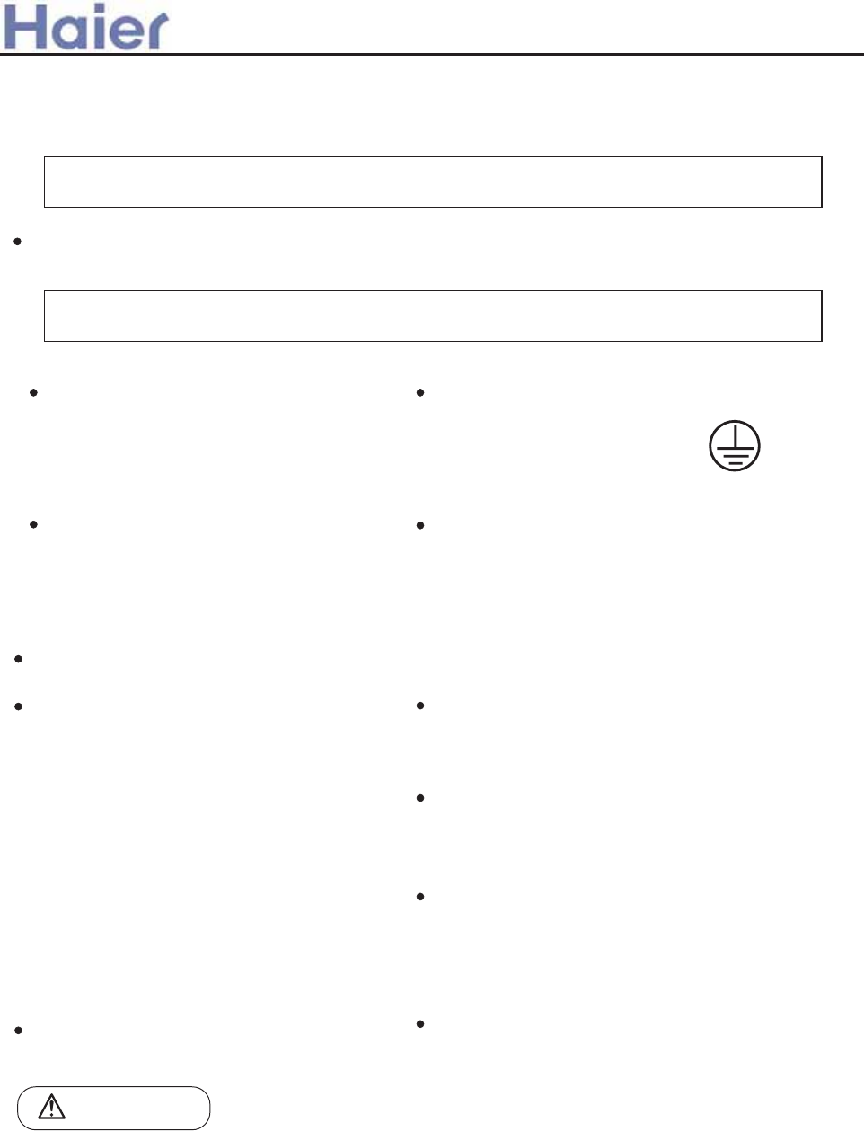
WARNING !
CAUTION !
Please ask the dealer or specialist to install, never try by the users themselves. After the installation please
be sure of the following conditions.
Incorrect installation may cause water leaking, shock and fire hazard.
Please call dealer to install the air-conditioner.
Air-conditioner can't be installed in the
envi-ronment with inflammable gases
because the inflammable gases near to
air-conditioner may cause fire hazard.
Installed electrical-leaking circuit breaker.
Connect earthing wire.
Use discharge pipe correctly to ensure efficient
discharge.
[Location]
[Wiring]
[Operating noise]
It easily cause electrical shock without circuit
breaker.
Air-conditioner should be located in well-vented
and easily-accessible place.
Air-conditioner should not be located in the
following places:
(a) Places with machine oils or other oil
vapours.
(b) Seaside with high salt content in the air.
(c) Near to hot spring with high content of
sulfide gases.
(d) Area with frequent fluctuation of voltage
e.g. factory, etc.
(e) In vehicles or ships.
(f) Kitchen with heavy oil vapour or humidity.
(g) Near to the machine emitting electric-
magnetic waves.
(h) Places with acid, alkali vapuor.
TV, radio, acoustic appliances etc are at least
Earthing wire should not be con-
nected to the gas pipe, water
pipe, lightning rod or phone line,
incorrect earthing may cause
Incorrect pipe use may cause water leaking.
supply wire, connecting wire, pipes, otherwise images
may be disturbed or noises be created.
As required, take measures against heavy snow.
Air-conditioner should be equipped with special power
supply wire.
Choose the following locations:
(a) Capable of supporting air-conditioner weight,don't
increase operating noise and vibration.
(b) Hot vapour from outdoor unit outlet and operating
noise don't disturb neighbour.
No obstacles around the outdoor unit outlet.
Earthing
For authorized service personnel only
WARNING
(1) For the room air conditioner to operate satisfactorily, install it as outlined in this installation manual.
(2) Connect the indoor unit and outdoor unit with the room air conditioner piping and cords available
from our standard parts. This in stallation manual describes for the correct connections so that the
installation set available from our standard parts should be used.
(3) Installation work must be performed in accordance with national wiring standardsby authorized
personnel only.
(4) Never cut the power cord, lengthen or shorten the cord, or change the plug.
>a__WcU[S^<[c>a`V[e[a`Wc
6.3 Convertible indoor unit (AC28-AC60)
-81-
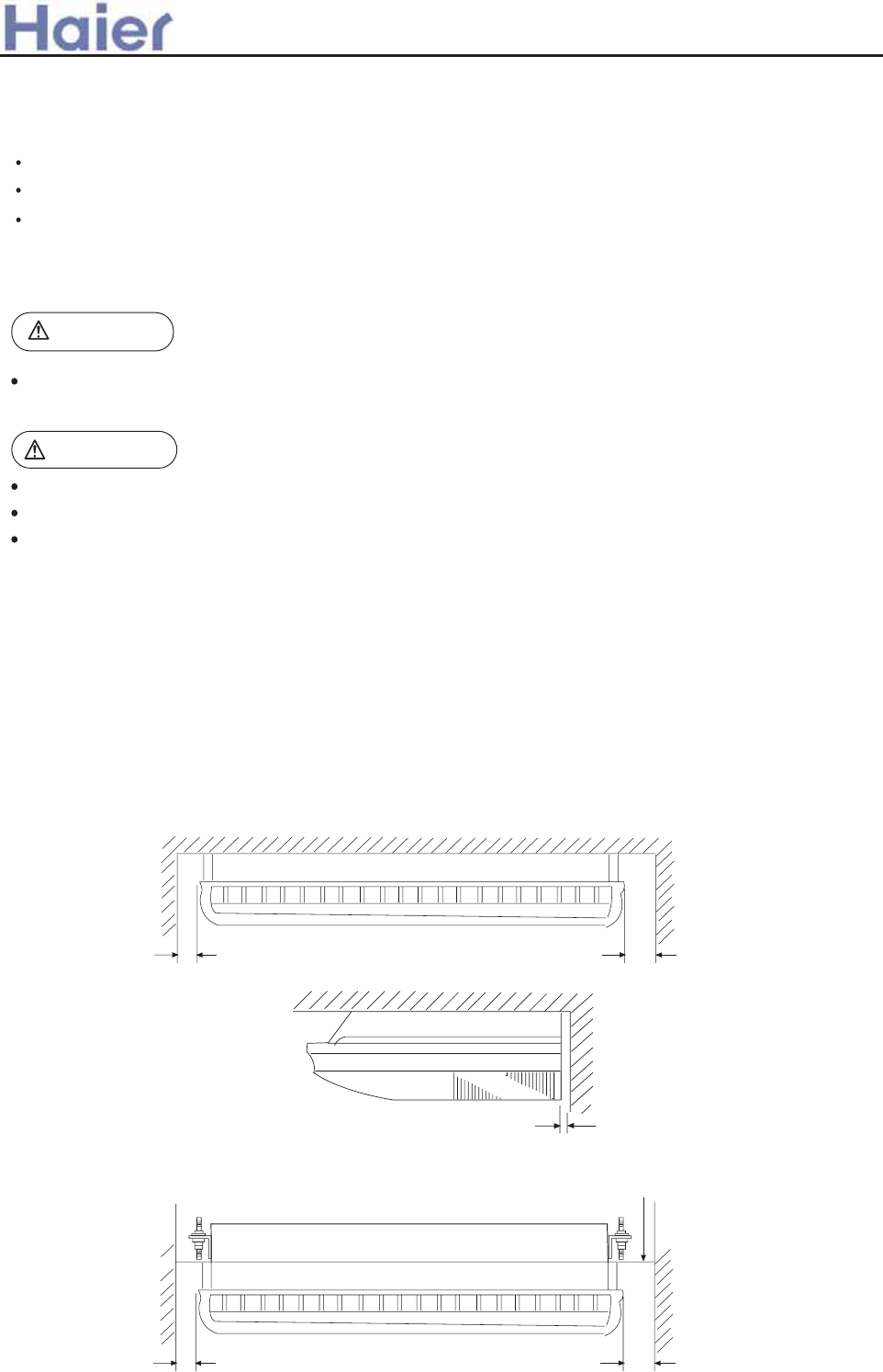
SELECTING THE MOUNTING POSITION
WARNING
CAUTION
Be careful not to scratch the room air conditioner when handing it.
After installation, explain correct operation to the customer, according to the operating manual.
Let the customer keep this installation manual because it will be used when the room air conditioner is
serviced or moved.
(5) Also, do not use an extension cord.
(6) Plug in the power cord plug firmly. If the receptacle is loose, repair it before using the air conditioner.
(7) Do not turn on the power until all installation work is done.
Do not install where there is the danger of combustible gas leakage.
Do not install near heat sources.
If children under 10 years old may approach the unit, take preventive measures so that they cannot
reach the unit.
Install at a place that can withstand the weight of the indoor units and install positively so that the units
will not topple or fall.
(1) Install the indoor unit level on a strong wall which is not subject to vibration.
(2) The inlet and outlet ports should not be obstructed : the air should be able to blow all over the room.
(3) Do not install the unit where it will be exposed to direct sunlight ,
(6) Take servicing , etc.into consideration and leave the spaces shown in (Fig.1 or 2) .
Also install the unit where the filter can be removed .
(4) Install the unit where connection to the outdoor unit is easy.
(5) Install the unit where the drain pipe can be easily installed.
0.4"(10mm)
over
For mounted on the ceiling:
Ceiling
INDOOR UNIT
3"(80mm)
over
6"(150mm)
over
Fig. 1
For half concealed installation:
3"(80mm)
over
6"(150mm)
over
Ceiling panel
Fig. 2
INDOOR UNIT
>a__WcU[S^<[c>a`V[e[a`Wc
-82-
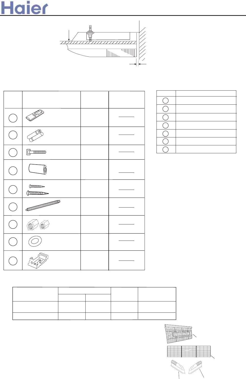
Optional parts
ACCESSORIES
Standard accessories:
INSTALLATION PROCEDURE
Install the room air conditioner as follows:
CONNECTION PIPE REQUIREMENT
1) REMOVE THE INTAKE GRILL AND SIDE COVER
(1) Remove the two Air filters
Ceiling panel
Mark Parts name
Adhesive tape
Saddle (L.S) with screws
Drain hose
Heat insulation material
Piping hole cover
Putty
Plastic clamp
A
B
C
D
E
F
G
1
2
3
4
5
1
2
4
1+1
2+2
No. Accessory parts Qty.
Remote controller
Battery
Wire clamp
Heat
insulation
sheathing
Screw
Screw cap
Remote
controller
bracket
6
7
1
1+1
Remarks
Drain hose 1
9
88
Flat washer
(2) Remove the two intake grilles
(3) Remove the Side cover A (Right and left side)
(4) This air conditioner can be set up to intake fresh air .
For information about how to install for fresh-air intake, refer to
page 22 "FRESH-AIR INTAKE".
Side cover A (Right side)
Side cover A (Left side)
Intake grille
Air filter
0.4"(10mm)
over
Ceiling panel
>a__WcU[S^<[c>a`V[e[a`Wc
Table 1
Model
Diameter
Liquid side Gas side
Maximum
length
Maximum height
(between indoor
and outdoor)
9.52 mm 19.05mm 50 m 30 m
9.52 mm 15.88mm 30 m 20 m
For series 362, 482
For series 282
602
-83-
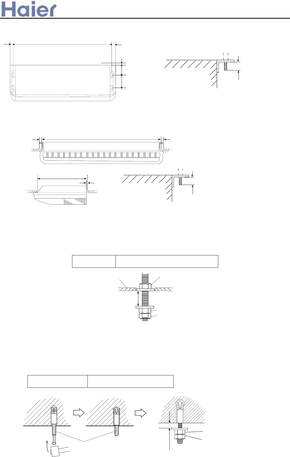
2) LOCATION OF CEILING SUSPENSION BOLTS
For half-concealed installation
Supension-bolt pitch should be as shown in Fig.4.
Ceiling Opening:1530mm
40mm 40mm
Ceiling panel
Suspension bolt should
extend outward 30 to 50mm.
Ceiling Opening:640mm
Ceiling panel
15mm
Suspension bolt should
extend outward 30 to 50mm.
Suspension bolt pitch 1530mm
30mm 30mm
INDOOR UNIT (TOP VIEW)
Dimensions
(Space Required for
installation)
10mm
155mm
300mm
Fig. 3
Fig. 4
DRILLING THE HOLES AND ATTACHING THE SUAPENSION BOLTS
IF USING ANCHOR BOLTS
(1) Drill holes for anchor bolts at the locations at which you will set the suspension bolts.Note that anchor
bolts (to be obtained locally).
(2) Install the anchor bolts ,then temporarily attach special nut "B" (included) and a locally-procurde M10
nut to each of the bolts. (See Fig.6.)
(1) Drill 25mm-diameter holes at the suspension-bolt locations.
(The two special nuts are provided with the unit. The M10 nut must be obtained locally.) Refer to Fig.5.
(2) Install the bolts, then temporarily attach Special nuts A and B and a normal M10 nut to each bolt.
Ceiling panel
10 to 15 mm
Special nut A (included)
M10 nut (Obtained locally)
Special nut B (included)
Bolt Strength 980 to 1470 N (100 TO 150 kgf)
Fig. 5
Anchor-Bolt Strength 980 to 1470 N (100 TO 150 kgf)
M10 Nut
(Obtaied locally)
Special nut B
(included)
10 to 15 mm
M10 Nut
(Obtaied locally)
Fig. 6
>a__WcU[S^<[c>a`V[e[a`Wc
-84-
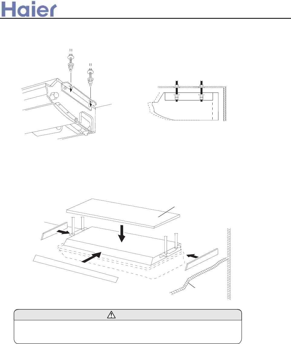
INSTALLING THE COUPLER HEAT INSULATION
After checking for gas leaks, insulate by wrapping insulation around the two parts (large and small) of the
indoor unit coupling, using the coupler hest insulation.
After installling the coupler heat insulation, wrap both ends with vinyl tape so that there is no gap.
Secure both ends of the heat insulation material using nylon fasteners.
INSTALLING THE INDOOR UNIT
(1) Lift unit so that suspension bolts pass through suspension fittings at the sides (four places),and slide
the unit back.(See Fig.8.)
FOR HALF-CONCESLED INSTALLATION
In order to check the drainage, be sure to use a level during installation of the
indoor unit. If the installation site of the indoor unit is not level, water leskage
may occur
CAUTION
When installing the indoor unit in a semi-concesled orientation, make sure to reinforce the insulation of
the unit on all sides. Drops of water may fall from the unit if it is not thoroughly insulated.
Glass wool insulate
(10 to 20mm thick )
INDOOR UNIT
(Top view)
Wall
Ceiling pannel
(2) Fasten the indoor unit into place by tightening-up the special "B",blots and the M10 nuts. Make sure
that unit is secure and willl not shift back and forth.
Fig. 9
Ceiling panel
Wall
Wall
Ceiling
Fig. 7 Fig. 8
>a__WcU[S^<[c>a`V[e[a`Wc
-85-
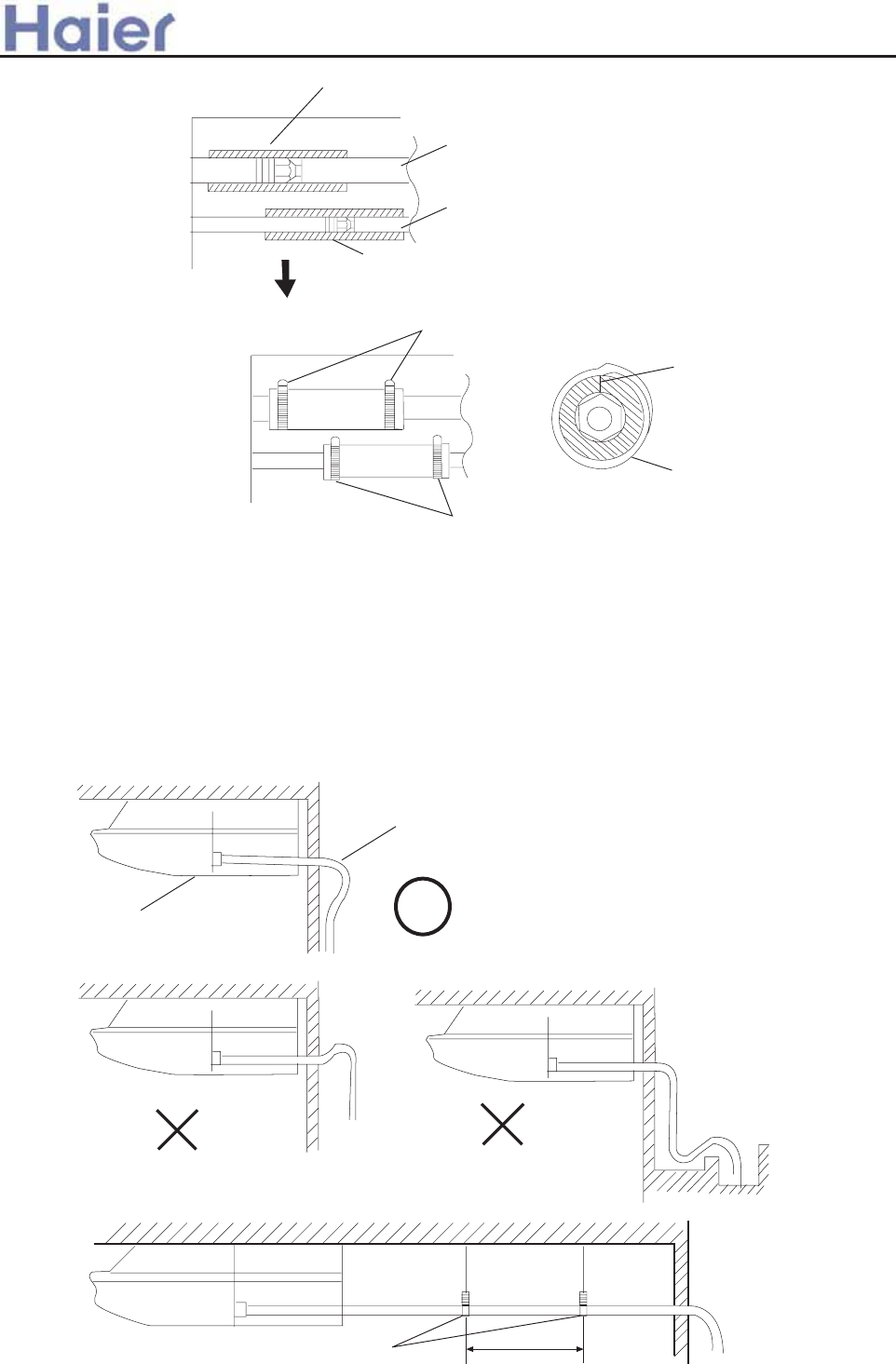
When using an auxiliary pipe, make sure that the fastener used is insulated in the sane way.
Indoor unit
Nylon fastner (large)
Nylon fastner (small)
No gap
Coupler heat insulation
DRAIN PIPING
Install the drain pipe with downward gradient (1/50 to 1/100) and so there are no rises or traps in the pipe.
Use general hard polyvinyl chloride pipe (VP25)[outside diameter 38 mm.]
During installation of the drain pipe,be careful to avoid applying pressure to the drain point of the unit.
When the pipe is long,install supporters(Fig 11).
Do not perform air bleeding.
Always heat insulate (8mm or over thick) the indoor side of the drain pipe.
BAD BAD
Bracket 5 to 6.5 ft
(1.5 to 2m)
Fig. 11
Coupler heat insulation(large)
Coupler pipe (large)
Coupler pipe (small)
Coupler heat insulation(small)
Indoor unit
Fig. 10
GOOD
>a__WcU[S^<[c>a`V[e[a`Wc
-86-
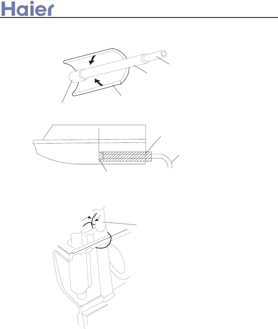
(1) Install insulation for the drain pipe.(See Fig.12 and 13)
Cut the included insulation material to an appropriate size and adhere it to the pipe.
Insulation for Drain pipe
(To be obtained locally.Length
shoud be at least 8mm)
Indoor unit(drain port)
Drain pipe insulation
Drain pipe
Indoor unit
No gap 10mm or over
Drain pipe
Drain pipe insulation
(2) If "Right rear piping ":fasten the drain pipe with VT wires so that the pipe slopes
Fig. 12
Fig. 13
ELECTRICAL WIRING
HOW TO CONNECT WIRING TO THE TERMINALS
(1)Cut the wire and with a wire cutter or wire-cutting pliers,then strip the insulation to about 15/16"(25mm)
of expose the solid wire.
(2)Using a screwdriver ,remove the terminal screw(s) on the terminal board.
(3)Using pliers,bend the solid wire to form a loop suitable for the terminal screw.
B.For strand wiring
(1)Cut the wire and with a wire cutter or wire-cutting pliers,then strip the insulation to about 3/8"(10mm)
of expose the solid wire.
(2)Using a screwdriver ,remove the terminal screw(s) on the terminal board.
A.For solid core wiring (or F-cable)
Indoor unit (rear view)
VT wire
Drain hose
Fig. 14
>a__WcU[S^<[c>a`V[e[a`Wc
correctly within
the indoor unit.
-87-
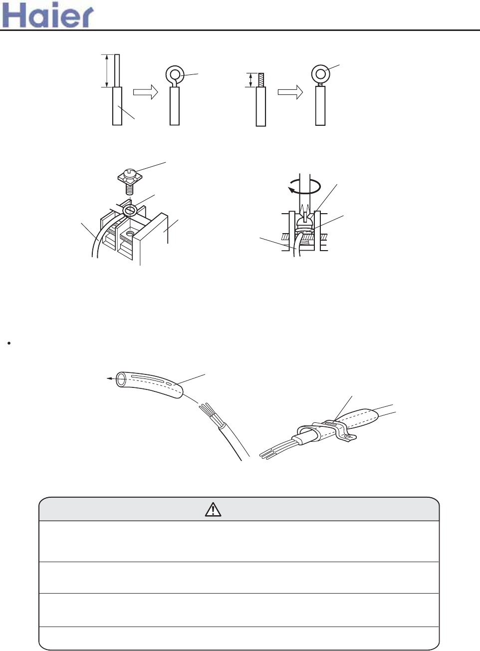
Insulation tube
Cord clamp
Use VW-1, 0.5 to 1.0 mm thick, PVC tube as the insulation tube.
CAUTION
(1) Match the terminal block numbers and connection cord colors with those of the
outdoor unit. Erroneous wiring may cause burning of the electric parts.
(2) Connect the connection cords firmly to the terminal block. Imperfect installation
may cause a fire.
(3) Always fasten the outside covering of the connection cord with the cord clamp.
(If the insulator is chafed, electric leakage may occur.)
(4) Always connect the ground wire.
ELECTRICAL REQUIREMENT
Electric wire size and fuse capacity:
After passing the connection cord and power cable through the insulation tube, fasten it with the cord
clamp, as shown in Fig.16
HOW TO FIX CONNECTION CORD AND POWER CABLE AT THE CORD CLAMP
Screw with
special washer
Round
terminal
Wire
Terminal
block
Screw with
special washer
Round
terminal
Wire
A. Solid wire
B. Strand wire
Round terminal
Loop
Insulation
Strip 15/16"(25mm)
Strip 15/16"(25mm)
Fig. 15
>a__WcU[S^<[c>a`V[e[a`Wc
Fig. 16
-88-
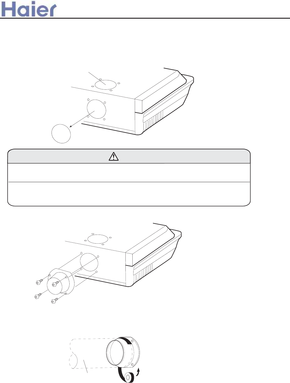
(1) Remove the cord clamp.
(2) Put the end of the connection cords to the positions shown in Fig.20.
(3) Connect the end of the connection cord fully into the terminal block.
(4) Fasten the connection cord with a cord clamp.
(5) Fasten the end of the connection cord with the screw.
(6) For series 28,36,42,52, the power cable and connecting cable are self-provided.
FRESH-AIR INTAKE
(1)Take away the knockout hole for the fresh-air intake,as shown in Fig.17.(If using half-concealed
installation ,take down the top knockout hole instead)
CAUTION
(1)When removing the cabinet(iron plate),be careful not to damage the indoor unit
internal parts and surrounding area(outer case).
(2)When processing the cabinet(iron plate),be careful not to injury yourself with
burrs,etc.
(2)Fasten the round flange (optional) to the fresh air intake,as shown in Fig.18.(If using half-concealed
installation, attach to the top.)
[After completing "INDOOR UNIT INSTALLATION"....]
(3)Connect the duct to the round flange.
(4)Seal with a band and vinyl tape,etc.so that air does not leak from the connection.
Duct
Fig. 17
Fig. 18
Fig. 19
For half-concealed
Round duct (option parts)
CONNECTION CORDS
>a__WcU[S^<[c>a`V[e[a`Wc
-89-
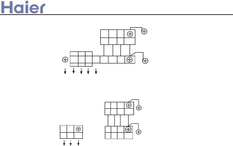
>a__WcU[S^<[c>a`V[e[a`Wc
OUTDOOR UNIT
TERMINAL BLOCK
INDOOR UNIT
TERMINAL BLOCK
POWER SUPPLY:
380-400V, 3N~,50Hz
R S T
N 1 2 3
1 2 3
Y/G
Y/G
Fig. 20
OUTDOOR UNIT
TERMINAL BLOCK
For single phase (1PH, 220-230V~, 50Hz),outdoor unit.
1PH,220-230V~,50Hz
POWER SUPPLY:
INDOOR UNIT
TERMINAL BLOCK
L N
Y/G
1 2 3
1 2 3 Y/G
For three phase (380-400V, 3N~, 50Hz),outdoor unit.
-90-
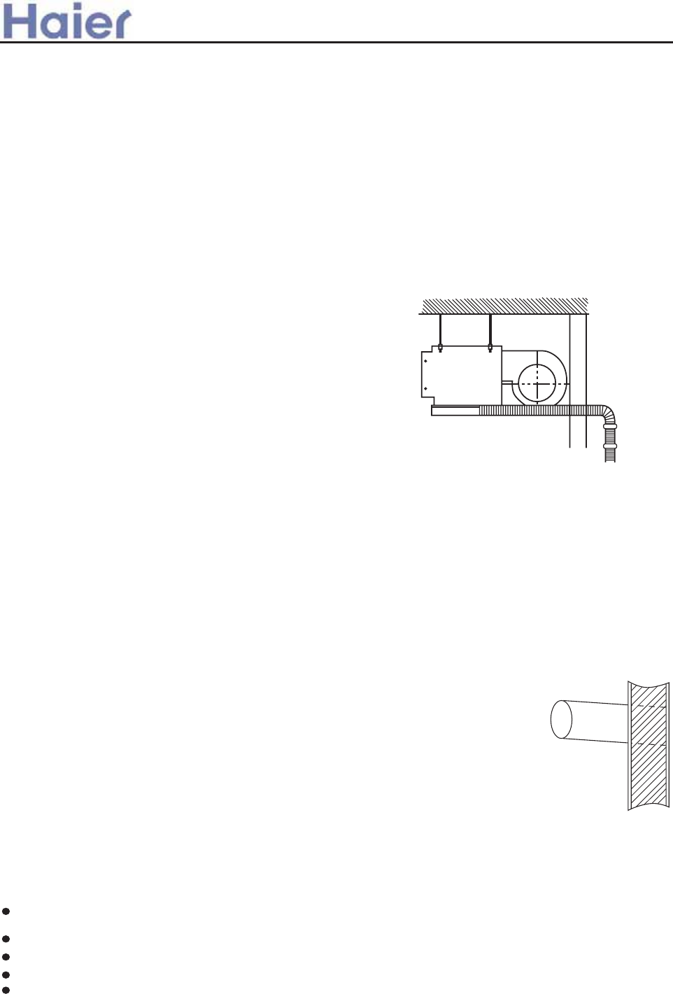
T`] af\ggjmfalk`Ydd Z]afklYdd]\ Yldg[Ylagfko`]j] [gd\ Yf\ `glYaj [gmd\ ]n]fdq[aj[mdYl]\4
T`] ^gddgoaf_ dg[Ylagfkk`gmd\ Z]Ynga\]\@
PdY[]koal`ja[`kYdl/k]Yka\] Yj]Y04
PdY[]koal` hd]flqg^_Ykkmd^a\]k/eYafdqaf oYje khjaf_ Yj]Yko`]j] l`] [ghh]j lmZ]Yf\ ZjYr]o]d\
ak]Ykqlg[gjjgkagf04
Lg[Ylagfkoal`em[`gad /af[dm\af_ e][`Yfa[Ydgad0Yf\ kl]Ye4
Lg[Ylagfkmkaf_ gj_Yfa[kgdn]flk4
PdY[]ko`]j] l`]j] Yj] eY[`af]k_]f]jYlaf_ HF]d][ljgeY_f]la[oYn]k4
PgkalagfkY\bY[]fllg\ggjgjoaf\goaf [gflY[loal` `a_`3`mea\alq]pl]jfYdYaj4/EYkqlg_]f]jYl]\]o04
Lg[Ylagfk^j]im]fldqmkaf_ kh][aYdY]jgkgdk4
<FC DLIILRGKE MLGKPO OFLQIB @C P?HCK A?NC LD1
74S]d][lkmalYZd] hdY[]kl`] gmld]lYaj [YfZ]k]fllgl`]
]flaj] jgge2Yf\ [gfn]fa]fllgdYqgmll`] [gff][lagf
hah]2[gff][lagfoaj] Yf\ l`] \jYafY_] hah] lggml\ggj4
84 T`] []adaf_ kljm[lmj] emkl Z]kljgf_ ]fgm_` lgkmhhgjl
l`] mfalo]a_`l4
94 T`] [gff][laf_ hah]2 \jYaf hah] Yf\ [gff][lagf oaj]
k`Ydd Z] YZd] lg_gl`gm_` l`] Zmad\af_ oYdd lg [gff][l
Z]lo]]f l`] af\ggj Yf\ gml\ggj mfalk4
:4 T`] [gff][laf_ hah] Z]lo]]f l`] af\ggj Yf\ gml\ggj mfalk Yko]dd Ykl`] \jYaf hah] k`Ydd Z] Ykk`gjl
YkhgkkaZd]4 /S]] Fa_mj] 70
;4 I^ alk f][]kkYjq lg Y\bmkl l`] ^addaf_ Yegmflg^ l`] j]^ja_]jYfl2 hd]Yk] j]^]j lgl`] afklYddYlagf eYfmYd
YllY[`]\ oal`l`] gml\ggj mfal4
<4 T`] [gff][laf_ ^dYf_] k`gmd\ Z] hjgna\]\ Zq l`] mk]j `aek]d^4
=4 T`] af\ggj mfal`Yklog oYl]j gmld]lk gf] g^ o`a[` akgZkljm[l]\ Yll`] ^Y[lgjq /oal` Y jmZZ]j [Yh04 Ofdq
l`] gmld]lfglgZkljm[l]\ /daima\ afd]lYf\ gmld]lka\]0 oadd Z] _]f]jYddq mk]\ \mjaf_ afklYddYlagf4 I^
Yhhda[YZd]2 Zgl`l`] gmld]lk k`gmd\ Z] mk]\ lg_]l`]j4
Ngl]@ T`] Y[[]kk `gd] emkl Z] hjgna\]\ \mjaf_ afklYddYlagf g^ af\ggj mfal^gj eYafl]fYf[]4
Fa_ 7
9KOP?II?PGLK OM?AC
2DPCN OCICAPGKE PFC GKOP?II?PGLK OM?AC|MNLACCB PFC DLIILRGKE OPCMO1
74 Djadd Y `gd] af l`] oYdd Yf\ afk]jll`] [gff][laf_ hah] Yf\ oaj] l`jgm_` Y PVC oYdd3
l`jgm_` lmZ] hmj[`Yk]\ dg[Yddq4 T`] oYdd `gd] k`Ydd Z] oal`YgmloYj\ \gof kdgh] g^ Yl
d]Ykl 757664 /S]] Fa_mj] 80
84 B]^gj] \jaddaf_ [`][c l`Yll`]j] akfg hah] gj j]af^gj[af_ ZYj bmkl Z]`af\ l`] \jaddaf_
hgkalagf4 Djaddaf_ k`Ydd Ynga\ Ylhgkalagfkoal` ]d][lja[ oaj] gj hah]4
94 Mgmfll`] mfalgfYkljgf_ Yf\ `gjargflYd Zmad\af_ jgg^4 I^ l`] ZYk]akfgl^aje2 aloadd
[Ymk] fgak]2 naZjYlagf gj d]YcY_]4
:4 Smhhgjll`] mfal^ajedq4
;4 C`Yf_] l`] ^gje g^ l`] [gff][lagf hah]2 [gff][lagf oaj] Yf\ \jYaf hah] kgl`Yll`]q
[Yf _g l`jgm_` l`] oYdd `gd] ]Ykadq4
Fa_ 8
EY[` g^ l`] Yaj k]f\af_ \m[lYf\ Yaj j]lmjf \m[lk`Ydd Z] ^ap]\ gf l`] hj]^YZja[Yl]\ hYf]d g^ l`] ^dggj
Zq l`] ajgf ZjY[c]l4
T`] j][gee]f\]\ \aklYf[] Z]lo]]f l`] ]\_] g^ l`] Yaj j]lmjf \m[lYf\ l`] oYdd akgn]j 7;6ee4
T`] _jY\a]flg^ l`] [gf\]fkYl] oYl]j hah] k`Ydd c]]h gn]j 7.4
T`] [gf\]fkYl]oYl]j hah] k`Ydd Z] l`]jeYd afkmdYl]\4
W`]f afklYddaf_ l`] []adaf_ Cgf[]Yd]\ lqh] af\ggj mfal2l`] Yaj j]lmjf \m[lemkl Z] \]ka_f]\ Yf\
afklYdd]\ /Yk^a_mj] k`gof04
>a__WcU[S^<[c>a`V[e[a`Wc
6.4 Ceiling concealed duct indoor unit (AD18-AD24)
-91-
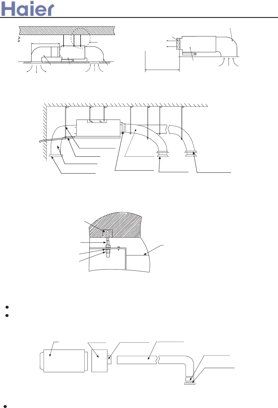
Ngl]@ W`]f [gff][laf_ l`] k`gjl\m[lk2mk]l`] dgo klYla[ l]jeafYdk2 o`a[` [gdgj ako`al]4
T`] \aklYf[] L ^jge l`] Yaj gmld]lg^ l`] \m[llgl`] Yaj gmld]lg^ l`] kaj [gf\alagf]j k`Ydd Z] fg egj] l`Yf7e4
Aaj \akljaZmlYjq
Aaj j]lmjf \m[l
Aaj j]lmjf Zdaf\
Smkh]f\af_ `ggc
DjYaf hah]
TjYfkalagf \m[l
Aaj gml\m[l
T`] kc]l[` eYh g^ dgf_ \m[l
Ta]3af g^ Yaj
\akljaZmlYjq
Ngl]@ W`]f [gff][laf_ l`] dgf_ \m[lk2mk]l`] ea\\d] klYla[ l]jeafYdk2 o`a[` [gdgj akj]\4
M> oa\] ]phYfkagf Zgdl
M> kmkh]f\]j k[j]o
M> oa\] dg[c oYk`]j
M> k[j]o fml
Aaj [gf\alagf]j
T`] \aklYf[] L ^jge l`] Yaj gmld]lg^ l`] \m[llgl`] Yaj gmld]lg^ l`] kaj [gf\alagf]j k`Yd Z] fg egj] l`Yf;e4
IfklYddYlagf g^ af\ggj mfal\m[l
74 IfklYddYlagf g^ Yaj k]f\af_ \m[l
T`akmfalmk]kjgmf\]\ \m[l2l`] \aYe]l]j g^ l`] \m[lak7>6ee4
T`] jgmf\ \m[lf]]\klgY\\YljYfkalagf \m[llg [gff][loal`l`] Yaj3k]f\af_ \m[lg^ af\ggj
mfal2l`]f [gff][loal`j]kh][lan] k]hYjYlgj4 AkFa_4 7 k`gof2 Ydd l`] ^Yf kh]]\ g^ Yfq g^ l`] k]hYjYlgjvk
Yaj gmld]lk`Ydd Z] Y\bmkl]\ YhhjgpaeYl]dq l`] kYe] lge]]ll`] j]imaj]e]fl^gj l`] jgge Yaj [gf\alagf]j4
If\ggj mfal^d]paZd] bgaflTjYfkalagf \m[lRgmf\]\ \m[l
Ufal@ee
Fa_4 7
Aaj \akljaZmlYjq
Ta]3af g^ Yaj
\akljaZmlYjq
84 IfklYddYlagf g^ Yaj j]lmjf \m[l
Uk] jan]llg [gff][ll`] Yaj j]lmjf \m[lgf l`] Yaj j]lmjf afd]lg^ l`] af\ggj mfal2l`]f [gff][ll`] gl`]j ]f\
oal`l`] Yaj j]lmjf Zdaf\4 AkFa_4 8 k`gof4
746e /mk] o`al]eglgj hdm_0
;46e/mk] j]\ eglgj hdm_0
[]adaf_
Yaj kmhhdq
+
Bmad\af_ jgg^ g^ afklYddYlagf
Yaj j]lmjf
Yaj j]lmjf Zgp
mfal
T`]j] k`gmd\ Z]
fg gZklY[d]k
oal`af 7e
Aaj gmld]l_jadd]
Aaj kmhhdq
Yaj j]lmjf
Yaj j]lmjf Zgp
mfal
>a__WcU[S^<[c>a`V[e[a`Wc
-92-
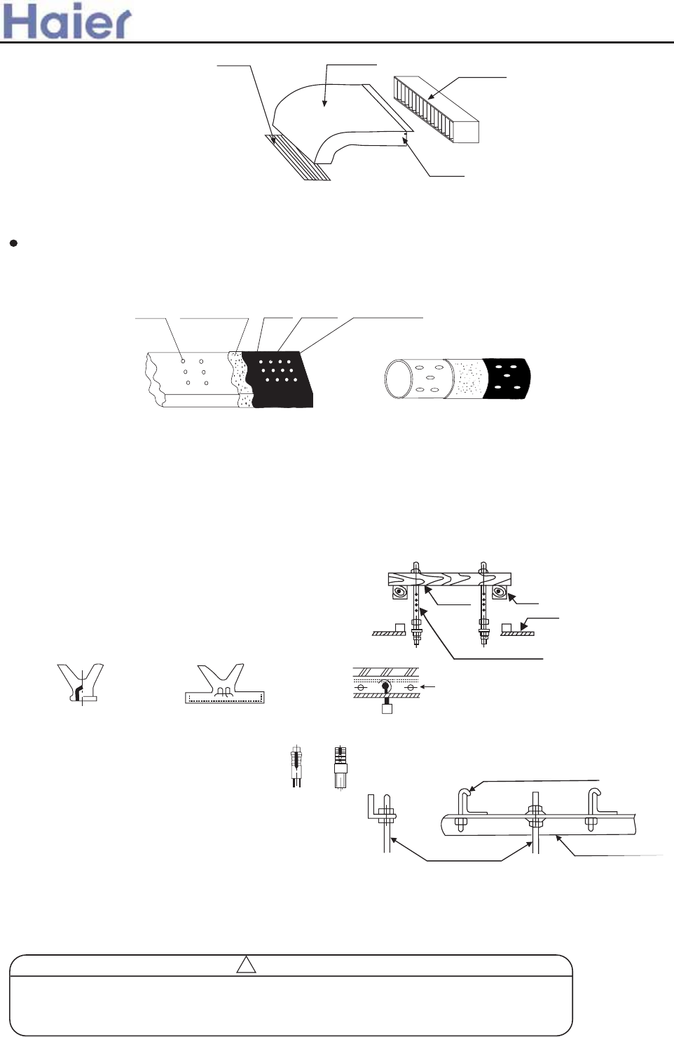
9 T`]jeYd afkmdYlagf g^ \m[l
Aaj3k]f\af_ \m[lYf\ Yaj j]lmjf \m[lk`Ydd Z] l`]jeYddq afkmdYl]\4 Fajkl kla[cl`] _dm]q fYad gf l`] \m[l2l`]f
YllY[` l`] `]Ylhj]k]jnYlagf [gllgf oal` Y dYq]j g^ laf^gad hYh]j Yf\ mk]l`] _dm]q fYad [Yh lg ^ap4 FafYddq mk]
l`] laf^gad Y\`]kan] lYh] lgk]Yd l`] [gff][l]\ hYjl4AkFa_4 9 k`gof4
Fa_4 9
_dm]q
fYad
_dm]q
fYad [Yh Y\`]kan] lYh]
laf^gad
`]Ylhj]k]jnYlagf
[gllgf
IfklYddaf_ l`] kmkh]fkagf k[j]o@
Uk]M>gjM76kmkh]fkagf k[j]ok/:2hj]hYj]\ af l`] ^a]d\0/o`]f l`] kmkh]fkagf k[j]o`]a_`l]p[]]\k64?e2
M76 kar] akl`] gfdq [`ga[]04T`]k]k[j]okk`Ydd Z] afklYdd]\ Yk^gddgokoal`khY[] Y\Yhlaf_ lg Yaj [gf\alagf]j
gn]jYdd \ae]fkagfkY[[gj\af_ lgl`] gja_afYd Zmad\af_ kljm[lmj]k4
Wgg\]f kljm[lmj]
AkimYj] ogg\ k`Ydd Z] kmhhgjl]\ Zq l`] Z]YekYf\ l`]f k]ll`] kmkh]fkagf k[j]ok4
N]o [gf[j]l]kdYZ
Tg k]loal` ]eZ]\\]\ hYjlk2^gmf\Ylagf Zgdlk ]l[4
Oja_afYd [gf[j]l]kdY\
Uk] `gd] `af_]2`gd] hdmf_]j gj `gd] Zgdl4
Sl]]d j]af^gj[]e]flkljm[lmj]
Uk]kl]]d Yf_d] gj f]o kmhhgjlkl]]d Yf_d] \aj][ldq4
SimYj] ogg\
B]Ye
Smkh]fkagf k[j]o
Gma\] hdYl] ]eZ]\\]\ hYjl
Kfa^] ]eZ]\\]\ hYjl
Fgmf\Ylagf Zgdl
Pah] kmkh]fkagf ^gmf\Ylagf Zgdl
Ijgf j]af^gj[]e]fl
HYf_af_ Zgdl
Smkh]fkagf k[j]o Smhhgjlkl]]d Yf_d]
Fa_4 8
If\ggj mfal
jan]l
Aaj j]lmjf \m[l
Aaj j]lmjf Zdaf\
HYf_af_ g^ l`] af\ggj mfal
FYkl]f l`] fmlgf l`] kmkh]fkagf k[j]o Yf\ l`]f `Yf_ l`] kmkh]fkagf k[j]o af l`]Tkdglg^ l`] kmkh]fkagf
hYjlg^ l`] mfal4 Aa\]\ oal` Y d]n]d e]l]j2Y\bmkl d]n]d g^ l`] mfaloal`af ;ee4
If gj\]j lg \jYaf oYl]j fgjeYddq2 l`] \jYaf hah] k`Ydd Z] hjg[]kk]\ Ykkh][a^a]\ af l`]
afklYddYlagf eYfmYd Yf\ k`Ydd Z] `]YlafkmdYl]\ lg Ynga\ \]o _]f]jYlagf4 Iehjgh]j `gk]
[gff][lagf eYq [Ymk] af\ggj oYl]j d]YcY_]4
x4?QPGLK
>a__WcU[S^<[c>a`V[e[a`Wc
-93-
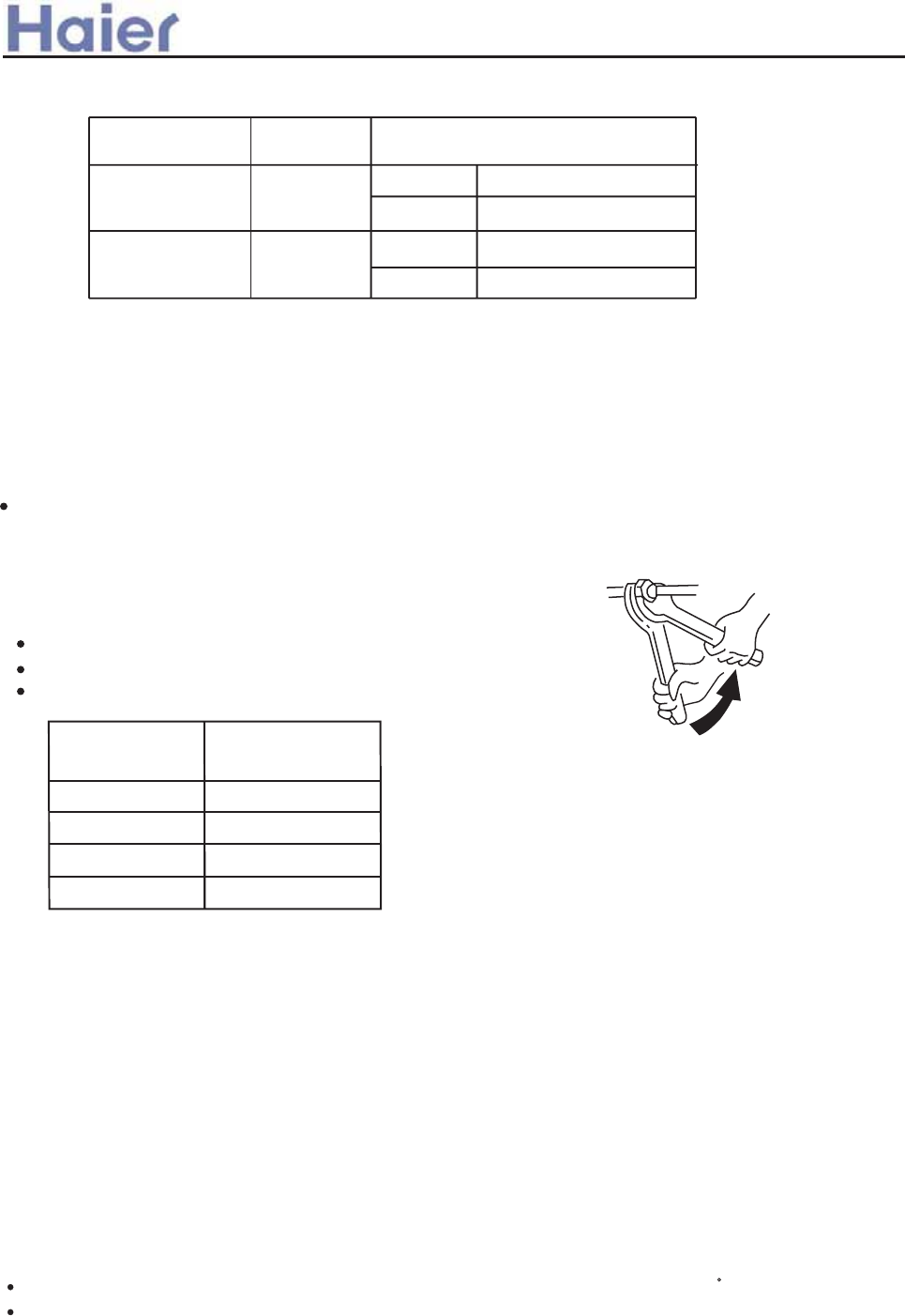
Double-spanner
operation
For series 182
For series 242
Pipe material and size
Pipe material Phosphorus deoxidized copper seamless
pipe (TP2M) for air conditioner
Pipe size
(mm)
Gas side 12.70
Liquid side 6.35
Supplementary refrigerant
The refrigerant supplementation shall be as specified in the installation instructions attached
with the outdoor unit.
The adding procedure shall be aided with a measuring meter for a specified amount
of supplemented refrigerant.
Requirement
Overfilling or underfilling of refrigerant will cause compressor fault. The amount of the
added refrigerant shall be as specified in the instructions.
Connection of refrigerant pipe
Conduct flared connection work to connect all refrigerant pipes.
The connection of indoor unit pipes must use double spanners.
The installing torque shall be as given in the following table.
Wall thicknessof connection pipe * 0.8mm
Connecting pipe
O.D.(mm)
6.35
9.52
12.70
15.88
Installing torque
(N-m)
11.8 (1.2kgf-m)
24.5 (2.5 kgf-m)
49.0 (5.0 kgf-m)
78.4 (8.0 kgf-m)
Type
Pipe size
(mm)
Gas side 15.88
Liquid side 9.52
Vacuum pumping
Open all valves
With a vacuum pump,create vacuum from the stop valve of the outdoor unit.
Emptying with refrigerant sealed in the outdoor unit is absolutely forbidden.
Open all the valves on the outdoor unit.
Gas leakage detection
Check with a leakage detector or soap water that if there is gas leakage at the pipe
connections and bonnets.
>a__WcU[S^<[c>a`V[e[a`Wc
Insulation treatment
Conduct insulation treatment on both the gas side and liquid side of pipes respectively
During cooling operation,both the liquid and gas sides are cold and thus shall be
insulated so as to avoid dew generation.
The insulating material at gas side shall be resistant to a temperature above 120 C
The indoor unit pipe connection part shall be insulated.
-94-
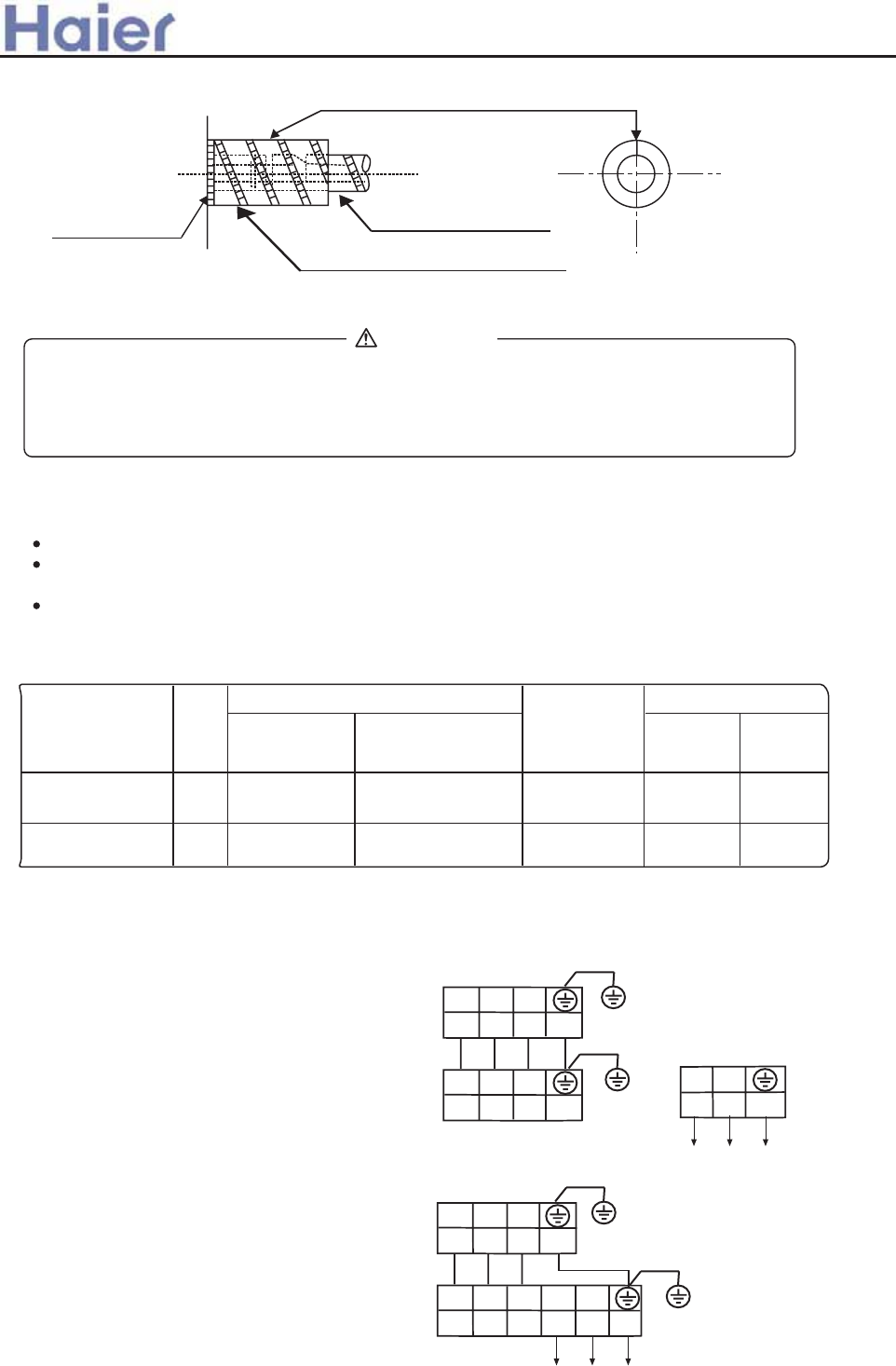
The notch upward(Attached detail view)
Indoor unit
Subsidiary insulation tube
Field piping side
Electric wiring
WARNING
DANGER OF BODILY INJURY OR DEATH
TURN OFF ELECTRIC POWER AT CIRCUIT BREAKER OR POWER SOURCE BEFORE
MAKING ANY ELECTRIC CONNECTIONS. GROUND CONNECTIONS MUST BE
COMPLETED BEFORE MAKING LINE VOLTAGE CONNECTIONS.
(1) Selection of size of power supply and interconnecting
Precautions for Electric wiring
Electric wiring work should be conducted only by authorized personnel.
Do not connect more than three wires to the terminal block. Always use round type crimped
terminal lugs with insulated grip on the ends of the wires.
Use copper conductor only.
30mA
Item Phase Switch breaker
(A)
Circuit breaker
Overcurrent
protector
Power
source wire
size
140 26 2.5mm2
Switch
break
Earth leakage breaker
Leak
curren
40A
30mA
140 26 4.0mm240A
Select wire sizes and circuit protection from table below. (This table shows 20 m length wires with
less than 2% voltage drop.)
For series 182
For series 242
(2) Wiring connection
Make wiring to supply power to the outdoor unit, so that the power for the indoor unit is supplied by
terminals.
.
>a__WcU[S^<[c>a`V[e[a`Wc
Q0B
Q0B
Q0B
Q0B
<?353<F@K<
<?353<F@<<
INM?IIKNHDM
M@KGDH<F=FI>E
2JC- 331.341Oj-61Ci
JIP@KLNJJFQ9
DH?IIKNHDM
M@KGDH<F=FI>E
234
234FH
INM?IIKNHDM
M@KGDH<F=FI>E
2JC- 331.341Oj-61Ci
JIP@KLNJJFQ9
DH?IIKNHDM
M@KGDH<F=FI>E
234
234HF
<?283<F@<<
-95-
Safety precautions of indoor unit
Please read these "Safety Precautions" firstly when performing the installation work.
Though the precautionary points indicated herein are divided under two headings, those points which
are related to the strong possibility of an installation done in error resulting in death or serious injury
are listed in the section. However, there is also a possibility of serious consequences
in relationship to the points listed in the section as well.
In either case, important safety related information is indicated, so by all means, properly observe all
that is mentioned.
After completing the installation, along with confirming that no abnormalities were seen from the operation
tests, please explain operating methods as well as maintenance methods to the user (customer) of
this equipment, based on the owner's manual.
Moreover, ask the customer to keep this sheet together with the owner's manual.
CAUTION
WARNING
WARNING
This system should be applied to places as office, restaurant, residence and the like. Application to inferior environment such
as engineering shop could cause equipment malfunction.
Please entrust installation to either the company which sold you the equipment or to a professional contractor. Defects from
improper installations can be the cause of water leakage, electric shocks and fires.
Execute the installation accurately, based on following the installation manual. Again, improper installations can result in water
leakage, electric shocks and fires.
When a large air-conditioning system is installed to a small room, it is necessary to have a prior planned countermeasure for
the rare case of a refrigerant leakage, to prevent the exceeding of threshold concentration. In regards to preparing this
countermeasure, consult with the company from which you perchased the equipment, and make the installation accordingly.
In the rare event that a refrigerant leakage and exceeding of threshold concentration does occur, there is the danger of a
resultant oxygen deficiency accident.
For installation, confirm that the installation site can sufficiently support heavy weight. When strength is insufficient, injury
can result from a falling of the unit.
Execute the prescribed installation construction to prepare for earthquakes and the strong winds of typhoons and hurricanes,
etc. Improper installations can result in accidents due to a violent falling over of the unit.
For electrical work, please see that a licensed electrician executes the work while following the safety standards related to
electrical equipment, and local regulations as well as the installation instructions, and that only exclusive use circuits are used.
Insufficient power source circuit capacity and defective installation execution can be the cause of electric shocks and fires.
Accurately connect wiring using the proper cable, and insure that the external force of the cable is not conducted to the terminal
connection part, through properly securing it. Improper connection or securing can result in heat generation or fire.
Take care that wiring does not rise upward, and accurately install the lid/service panel. Its improper installation can also result
in heat generation or fire.
When setting up or moving the location of the air conditioner, do not mix air etc. or anything other than the designated refrigerant
(R407C) within the refrigeration cycle.
Rupture and injury caused by abnormal high pressure can result from such mixing.
Always use accessory parts and authorized parts for installation construction. Using parts not authorized by this company
can result in water leakage, electric shock, fire and refrigerant leakage.
CAUTION
Execute proper grounding. Do not connect the ground wire to a gas pipe, water pipe, lightning rod or a telephone ground
wire. Improper placement of ground wires can result in electric shock.
The installation of an earth leakage breaker is necessary depending on the established location of the unit. Not installing
an earth leakage breaker may result in electric shock.
Do not install the unit where there is a concern about leakage of combustible gas.
The rare event of leaked gas collecting around the unit could result in an outbreak of fire.
For the drain pipe, follow the installation manual to insure that it allows proper drainage and thermally insulate it to prevent
condensation. Inadequate plumbing can result in water leakage and water damage to interior items.
>a__WcU[S^<[c>a`V[e[a`Wc
6.5 Med ESP duct indoor unit (AD18-AD48)
-96-
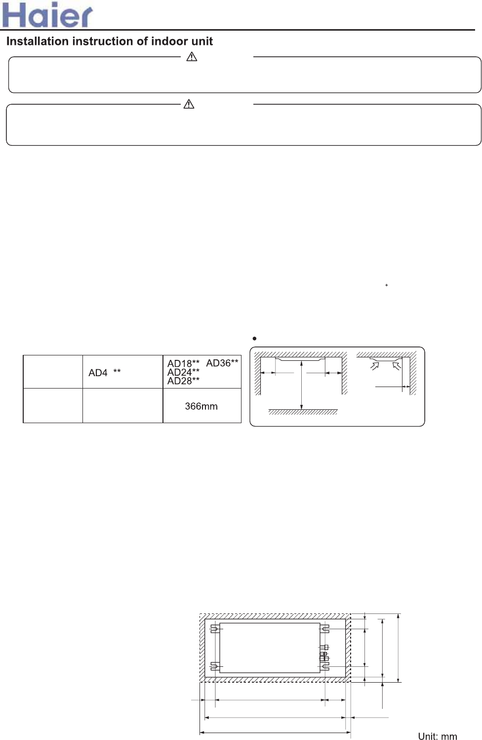
NOTICE
All Wiring of this installation must comply with NATIONAL, STATE AND LOCAL REGULATIONS.
These instructions do not cover all variations for every kind of installation circumstance. Should further
WARNING
BE SURE TO READ THESE INSTRUCTIONS CAREFULLY BEFORE BEGINNING INSTALLATION.
FAI-LURE TO FOLLOW THESE INSTRUCTIONS COULD CAUSE SERIOUS INJURY OR DEATH,
EQUIPMENT
(1) Preparation of indoor
Before or during the installation of the unit, assemble necessary optional panel etc. depending on the
specific type.
(2) Select places for installation satisfying following conditions and at the same time obtain the
consent on the part of your client user.
(a) Places where chilled or heated air circulates freely.
When the installation height exceeds 3m warmed air stays close to the ceiling. In such cases, suggest
your client users to install air circulators.
(b) Places where perfect drainage can be prepared and sufficient drainage.
(c) Places free from air disturbances to the suction port and blowout hole of the indoor unit, places
where the fire alarm may not malfunction or short-circuit.
(d) Places with the environmental dew-point temperature is lower than 28 and the relative
humidity is less than 80 %. (When installing at a place under a high humidity environment, pay sufficient
attention to the prevention of dewing such as thermal insulation of the unit. )
(e) Ceiling height shall have the following height.
(3) Avoid installation and use at those places
(a) Places exposed to oil splashes or steam (e.g. kitchens and machine plants).
Installation and use at such places incur deteriorations in the performance or corrosion with the heat
exchanger or damage in molded synthetic resin parts.
(b) Places where corrosive gas (such as sulfurous acid gas) or inflammable gas (thinner, gasoline,etc)
in generated or remains. Installation and use at such places cause corrosion in the heat exchanger
and damage in molded synthetic resin parts.
(c) Places adjacent to equipment generating electromagnetic waves or high-frequency waves such as
in hospitals.
Generated noise may cause malfunctioning of the controller.
50 or more
Obstacle
100 or
more 100 or
more
1000 or more
Unit: mm
Installation space
C
(4) Preparation for suspending the
(a) Size of hole at ceiling and position of
<Combination with silent panel>
57 A
B
C
(Hanging bolt position)
(Ceiling hole size)
(Panel dimensions)
137
30
30
(Ceiling ~ panel
wrap dimensions)
(Ceiling ~ panel
wrap dimensions)
(Hanging bolt position)
(Ceiling hole size)
(Panel dimensions)
75 545
690
750
70
(Pipe connection
side)
Combination
with silent
panel 416mm
>a__WcU[S^<[c>a`V[e[a`Wc
-97-
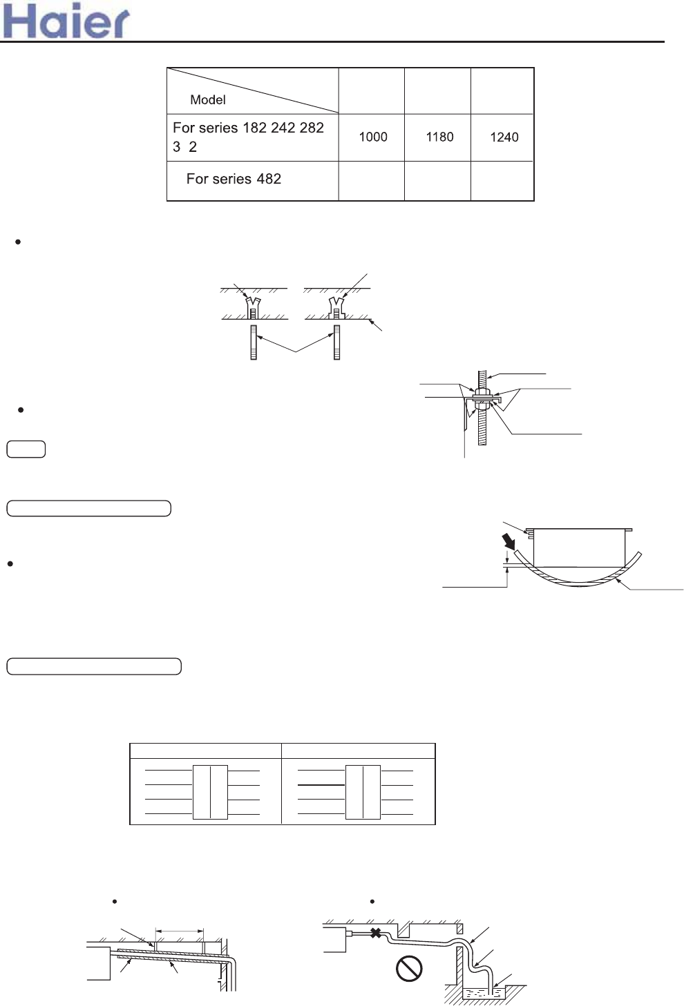
(b) Hanger bolts installation
Use care of the piping direction when the unit is installed.
Hanging bolt M10
Hole-in anchor
Hole-in plug
Insert
Concrete
(5) Installation of indoor unit
Fix the indoor unit to the hanger bolts.
When the dimensions of main unit and ceiling holes does not match, it can be adjusted with the slot holes of
hanging bracket.
Note
Adjusting to the levelness
(a) Adjust the out-of levelness using a level or by the following
method.
Make adjustment so that the relation between the lower surface
below.
(b) Unless the adjustment to the levelness is made properly,
malfunctioning or failure of the float switch may occur.
Tap selection on blower (When the high performance filter is used.)
Taps of blower unit are set at the standard selection at the shipping from factory. Where the static
pressure is raised by employing such option as the high performance filter, etc., change the connection
of connectors provided at the flank of control box as shown below.
(6) Drain
(a) Drain piping should always be in a downhill grade (1/50~1/100) and avoid riding across an elevation
PVC hose
Piping side
Supply water
Water level
0~5 mm
(0~0.2")
Bring the piping side slightly lower.
Hanging bolt
M10 nut
Main unit
M10 washer
M10 spring washer
Do not pipe under water
Keep free from traps
Avoid riding across an elevation
Air vent
Inproper pipingGood piping
1.5m ~ 2m
Suspension
bolts
Heat
insulation
A downhill grade
of 1/100 or more
Red
Yellow
White
Standard tap (at shipping) High speed tap
Black
White
Connector white
Connector white
Control box side
Moter side
Moter side
Red
Blue
Red
Yellow
White
Blue
Red
Yellow
White
Blue White
Blue
Red
>a__WcU[S^<[c>a`V[e[a`Wc
Dimensions ABC
1406 1600 1660
of the unit proper and water level in the hose becomes as given
-98-
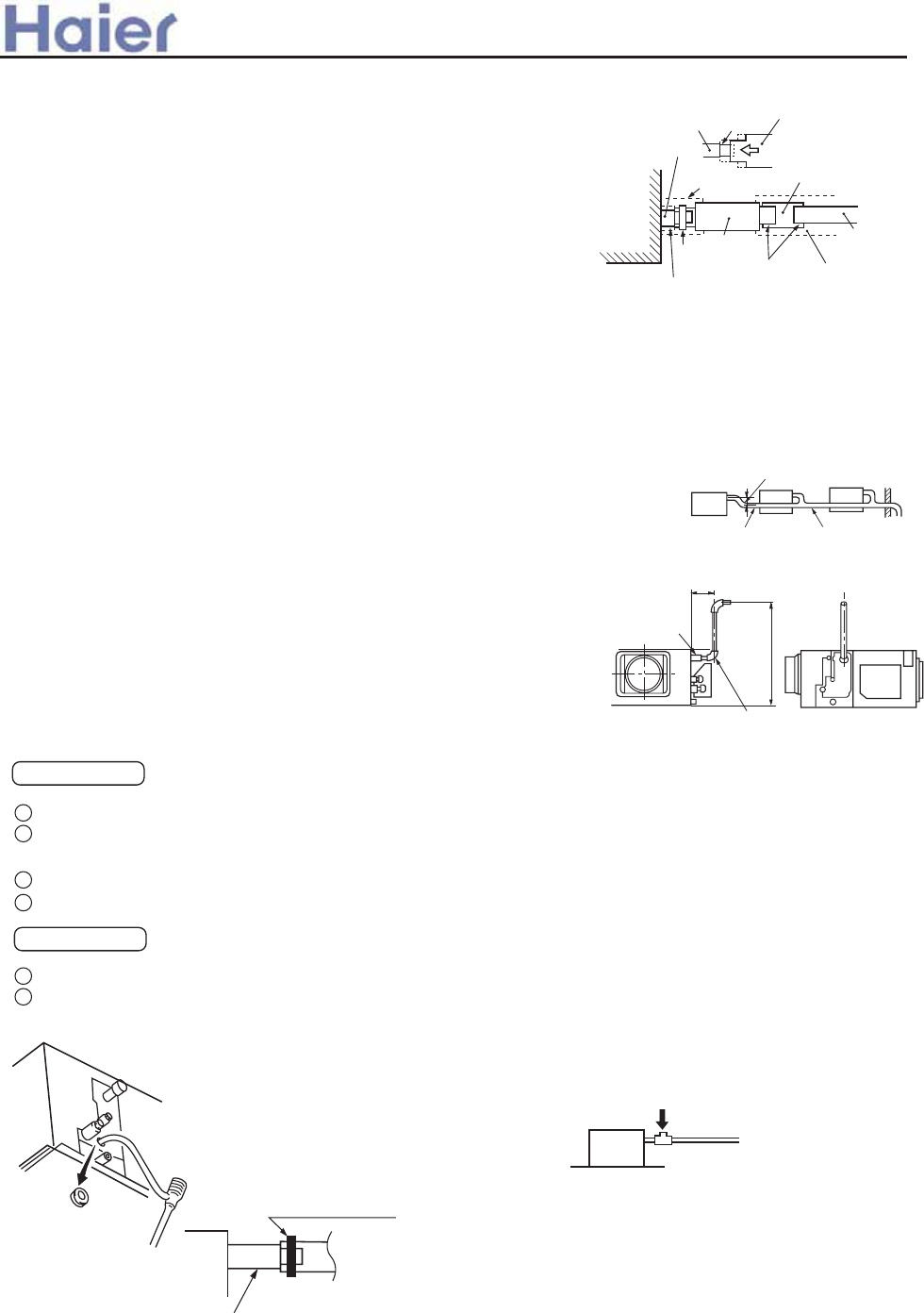
When connecting the drain pipe to unit, pay suffcient attention
not to apply excess force to the piping on the unit side. Also, fix
the piping at a point as close as possible to the unit.
For drain pipe, use hard PVC general purpose pipe VP-25(I.D.1")
which can be purchased locally. When connecting, insert a PVC
pipe end securely into the drain socket before tightening securely
using the attached drain hose and clamp. Adhesive must not be
used connection of the drain socket and drain hose (accessory).
Drain hose
Stage
difference
part
Drain socket
Drain socket
Main unit
VP 25 joint
(field purchased)
Pipe cover(large)
[for insulation]
(accessory)
VP 25
(field purchased)
Pipe cover
[for insulation]
(field purchased)
Drain hose
(accessory)
Pipe cover(small)
[for insulation]
(accessory)
Clamp
(accessory) Adhesion
(b)
(c)
VP 30
Secure the elevation as high as possible
(approx. 100 mm)
A downhill grade of
1/100 or more
Drain hose
Joint for VP 25
(Local procurement)
600
(Maximum local drain up dimension)
Right overhead
290~325mm
Attached drain hose clamp
Drain piping
Main unit
Drain situation can be checked with transparent socket
Remove grommet.
Make sure to install
it back after test.
Insert water supply hose
for 20 mm ~ 30 mm to
supply water.
(Insert hose facing
toward bottom.)
Pour water into a convex joint.
When constructing drain piping for several units, position the
common pipe about 100 mm below the drain outlet of each unit
as shown in the sketch. Use VP-30(11/4") or thicker pipe for this
purpose.
Be sure to provide heat insulation to hard PVC pipes of indoor
placement.
Do not ever provide an air vent.
The height of the drain head can be elevated up to a point 500
mm above the ceiling, and when an obstacle exists in the ceiling
space, elevate the piping to avoid the obstacle using an elbow
or corresponding gadget. When doing this, if the stretch for the
needed height is higher than 500 mm, the back-flow quantity of
drain at the event of interruption of the operation gets too much
and it may cause overflow at the drain pan. Therefore, make the
height of the drain pipe within the distance given in the sketch
below.
Avoid positioning the drain piping outlet at a place where generation
of odor may be stimulated. Do not lead the drain piping direct
into a sewer from where sulfur gas may generate.
Drainage
Conduct a drainage test after completion of the electrical work.
During the trial, make sure that drain flows properly through the piping and that no water leaks from
connections.
In case of a new building, conduct the test before it is furnished with the ceiling.
Be sure to conduct this test even when the unit is installed in the heating season.
Procedures
Supply about 1000 cc of water to the unit through the air outlet using a feed water pump.
Check the drain while cooling operation.
(d)
(e)
(f)
(h)
(g)
1
2
3
4
1
2
(In the electrical work has not been completed,
connect a convex joint in the drain pipe connection
to provide a water inlet. Then, check if water leaks
from the piping system and that drain flows through
the drain pipe normally.)
>a__WcU[S^<[c>a`V[e[a`Wc
-99-
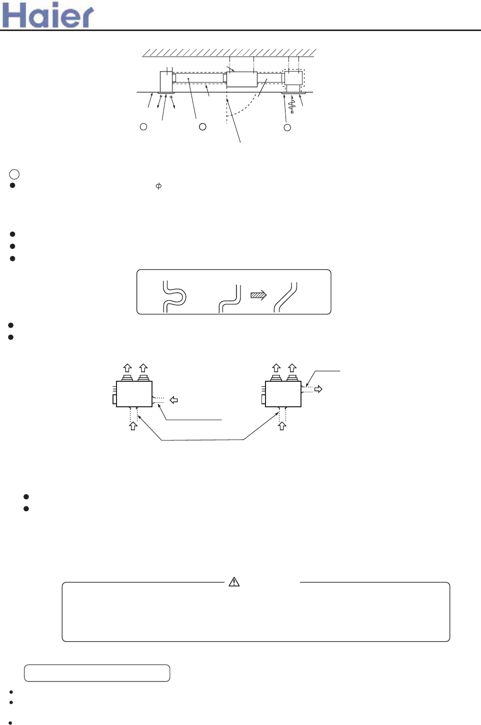
(7) Installation work for air outlet ducts
Calculate the draft and external static pressure and select the length, shape and blowout.
A Blowout duct
2-spot, 3-spot and 4-spot with 200 type duct are the standard specifications. Determine the number of spots
based on following table.
Note (1) Shield the central blowout hole for 2-spot.
(2) Shield the blowout hole around the center for 3-spot.
Limit the difference in length between spots at less than 2:1.
Reduce the length of duct as much as possible.
Reduce the number of bends as much as possible. (Corner R should be as larger as possible.)
Use a band. etc. to connect the main unit and the blowout duct flange.
Conduct the duct installation work before finishing the ceiling.
(8) Connection of suction, exhaust ducts
(a) Duct connection position
i) Fresh air inlet
Inlet can be selected from the side or rear faces depending on the working conditions.
Use the rear fresh air inlet when the simultaneous intake and exhaust is conducted.
(Side inlet cannot be used.)
ii) Exhaust (Make sure to use also the suction.)
Use the side exhaust port.
Good exampleBad exampleBad example
Ceiling surface
Heat
insulation Suction panel
(Silent panel)
Air conditioner main unit
B Special blowout
(Option)
A Blowout duct
(Optional or marketed item)
C
Hole for check
special inlet (option)
(with air filter)
inlet duct
(optional or
marketat item)
Electric wiring
WARNING
DANGER OF BODILY INJURY OR DEATH
TURN OFF ELECTRIC POWER AT CIRCUIT BREAKER OR POWER SOURCE BEFORE
MAKING ANY ELECTRIC CONNECTIONS. GROUND CONNECTIONS MUST BE
COMPLETED BEFORE MAKING LINE VOLTAGE CONNECTIONS.
(1) Selection of size of power supply and interconnecting
Precautions for Electric wiring
Electric wiring work should be conducted only by authorized personnel.
Do not connect more than three wires to the terminal block. Always use round type crimped terminal lugs with
insulated grip on the ends of the wires.
Use copper conductor only.
Exhaust hole
State seeing from top of unit
Side fresh air inlet
Rear fresh air inlet
Fig.1 Fig.2
>a__WcU[S^<[c>a`V[e[a`Wc
-100-
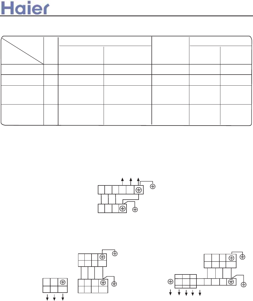
>a__WcU[S^<[c>a`V[e[a`Wc
Select wire sizes and circuit protection from table below. (This table shows 20 m length
wires with less than 2% voltage drop.)
(2) Wiring connection
Make wiring to supply power to the indoor unit, so that the power for the outdoor unit is
supplied by terminals.
Item
Model Phase Switch breaker
(A)
Circuit breaker
Overcurrent
protector
Power
source wire
size
(minimum)
30 20 2.5
Switch
breaker(A)
Earth leakage breaker
Leak
current(mA)
30
30
140 26 2.5 40
For series 242 282
3
L N
1 2 3 Y/G
INDOOR UNIT
TERMINAL BLOCK
POWER
1PH, 220-230V~, 50Hz
SUPPLY:
Y/G
1 2 3
OUTDOOR UNIT
TERMINAL BLOCK
For series 182
140 26 6.0 40
For series 282
For series
282 362 482
30
30
30
140 26 4.0 40
For series 242
1 2 3 N L
1 2 3
POWER
1PH, 220-230V~, 50Hz
SUPPLY:
OUTDOOR UNIT
TERMINAL BLOCK
INDOOR UNIT
TERMINAL BLOCK
POWER SUPPLY:
380-400V, 3N~, 50Hz
R S T N 1 2 3
1 2 3
Y/G
Y/G
Make wiring to supply power to the outdoor unit, so that the power for the indoor unit is
supplied by terminals.
INDOOR UNIT
TERMINAL BLOCK
OUTDOOR UNIT
TERMINAL BLOCK
Y/G
Y/G
362
For AD182AMEAA
-101-
362 and AD182AMERA For series 282 362 422 482
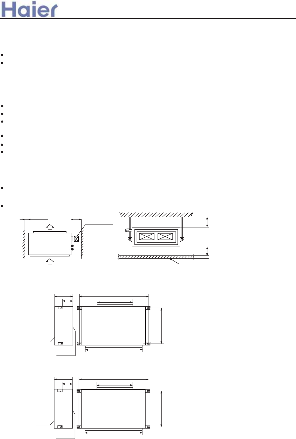
1. Before installation [Before finishing installation, do not throw the attached parts installation
needs]
2. Choose installation place
(1) The chosen installation place should meet the following requirements and get the users consent.
Place ensures ideal airflow distribution.
The passage of airflow has no obstacles.
When importing outside air, it should be imported directly from outdoors. (if the pipe can not be extended, it also can
not be imported from top)
Place ensures enough space for maintenance.
The pipe length between indoor and outdoor unit is in the permitted limit (referring to outdoor unit installation part).
The indoor unit, outdoor unit, electric wire and connection wire is at least 1m away from television and radio. This is
to avoid the image disturbance and noise caused by the above-mentioned home appliance. (Even if 1m away, if the
electromagnetic wave is too strong, it can also cause noise.)
(2) The height of ceiling
The indoor unit can install on the ceiling, which height is no more than 3m.
(3) Install and use the hoisting screw. Check if the installation place can bear the weight of unit assembly.
If not certain, strengthen it before install the unit.
(600x600)
Over 100 Over 900
Air out
Air in
Checking meatus
Ceiling
Over 300
Over 200
Confirm the way to move the unit to the installation place.
Before moving the unit to the installation place, do not remove their packages.
When have to remove the package, use a soft material or protection board with rope to lift the unit assembly to
avoid unit damage or bumping a scrape.
(1) The position relation among hoisting screw (unit: mm)
360 890
250
794
600
750
Down side
Up side
360 1270
250
794
853
1103
Down side
Up side
3. Preparation before installation
AD282AHEAA
AD482AHEAA
AD362AHEAA
>a__WcU[S^<[c>a`V[e[a`Wc
AD602AHEAA
AD362AHERA
6.6 High ESP duct indoor unit (AD28-AD60)
-102-
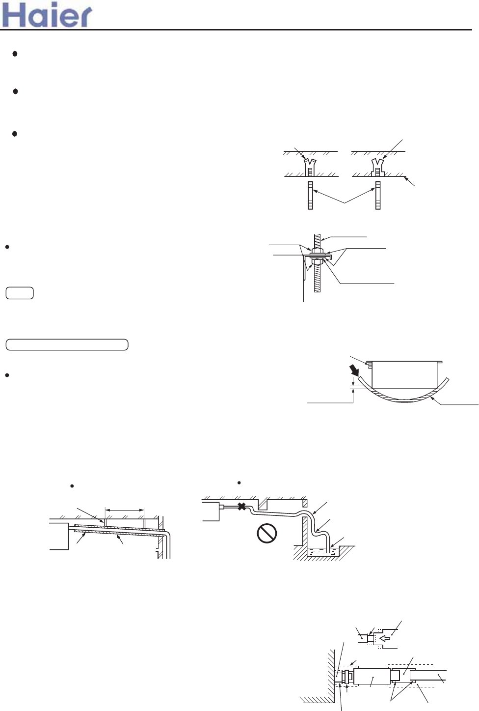
(3) Hanger bolts installation
Use care of the piping direction when the unit is installed.
Hanging bolt M10
Hole-in anchor
Hole-in plug
Insert
Concrete
(2) If necessary, cut the opening installation and checking needed on the ceiling. (If has ceiling)
Before installation, finish the preparation work of all the pipes (refrigerant, drainage) and wire (wire controller
connection wire, indoor and outdoor unit connection wire) of indoor unit, so that after installation, they can be
immediately connected with outdoor unit.
Cut the opening on the ceiling. Maybe it needs to strengthen the ceiling to keep the ceiling even and flat and
prevent the ceiling from vibration. For details, please consult to the builder.
(Use M10 screw bolt)
In order to bear the weight of the unit, for existed
ceiling, using foundation screw bolt, for new ceiling,
using burying embedded screw bolt, burying screw
bolt or spot supplied other parts.
Before going on installation, adjust the gaps with ceiling.
4. Installation of indoor unit
Fix the indoor unit to the hanger bolts.
If required, it is possible to suspend the unit to the beam, etc.
Directly by use of the bolts without using the hanger bolts.
When the dimensions of main unit and ceiling holes does not match, it can be adjusted with the slot holes of hanging
bracket.
Note
Adjusting to the levelness
(a) Adjust the out-of levelness using a level or by the following method.
Make adjustment so that the relation between the lower surface
of the unit proper and water level in the hose becomes as given
below.
(b) Unless the adjustment to the levelness is made properly, malfunctioning or failure of the float switch may occur.
PVC hose
Piping side
Supply water
Water level
0~5 mm
(0~0.2")
Bring the piping side slightly lower.
Hanging bolt
M10 nut
Main unit
M10 washer
M10 spring washer
Drain hose
Stage
difference
part
Drain socket
Drain socket
Main unit
VP 25 joint
(field purchased)
Pipe cover(large)
[for insulation]
(accessory)
VP 25
(field purchased)
Pipe cover
[for insulation]
(field purchased)
Drain hose
(accessory)
Pipe cover(small)
[for insulation]
(accessory)
Clamp
(accessory) Adhesion
For drain pipe, use hard PVC general purpose pipe VP-25(I.D.1")
which can be purchased locally. When connecting, insert a PVC
pipe end securely into the drain socket before tightening securely
using the attached drain hose and clamp. Adhesive must not be
used connection of the drain socket and drain hose (accessory).
(c)
5. Drain Piping
(a) Drain piping should always be in a downhill grade (1/50~1/100) and avoid riding across an elevation or making
traps.
When connecting the drain pipe to unit, pay suffcient attention not to apply excess force to the piping on the unit
side. Also, fix the piping at a point as close as possible to the unit.
Do not pipe under water
Keep free from traps
Avoid riding across an elevation
Air vent
Inproper piping
Good piping
1.5m ~ 2m
Suspension
bolts
Heat
insulation
A downhill grade
of 1/100 or more
(b)
>a__WcU[S^<[c>a`V[e[a`Wc
-103-
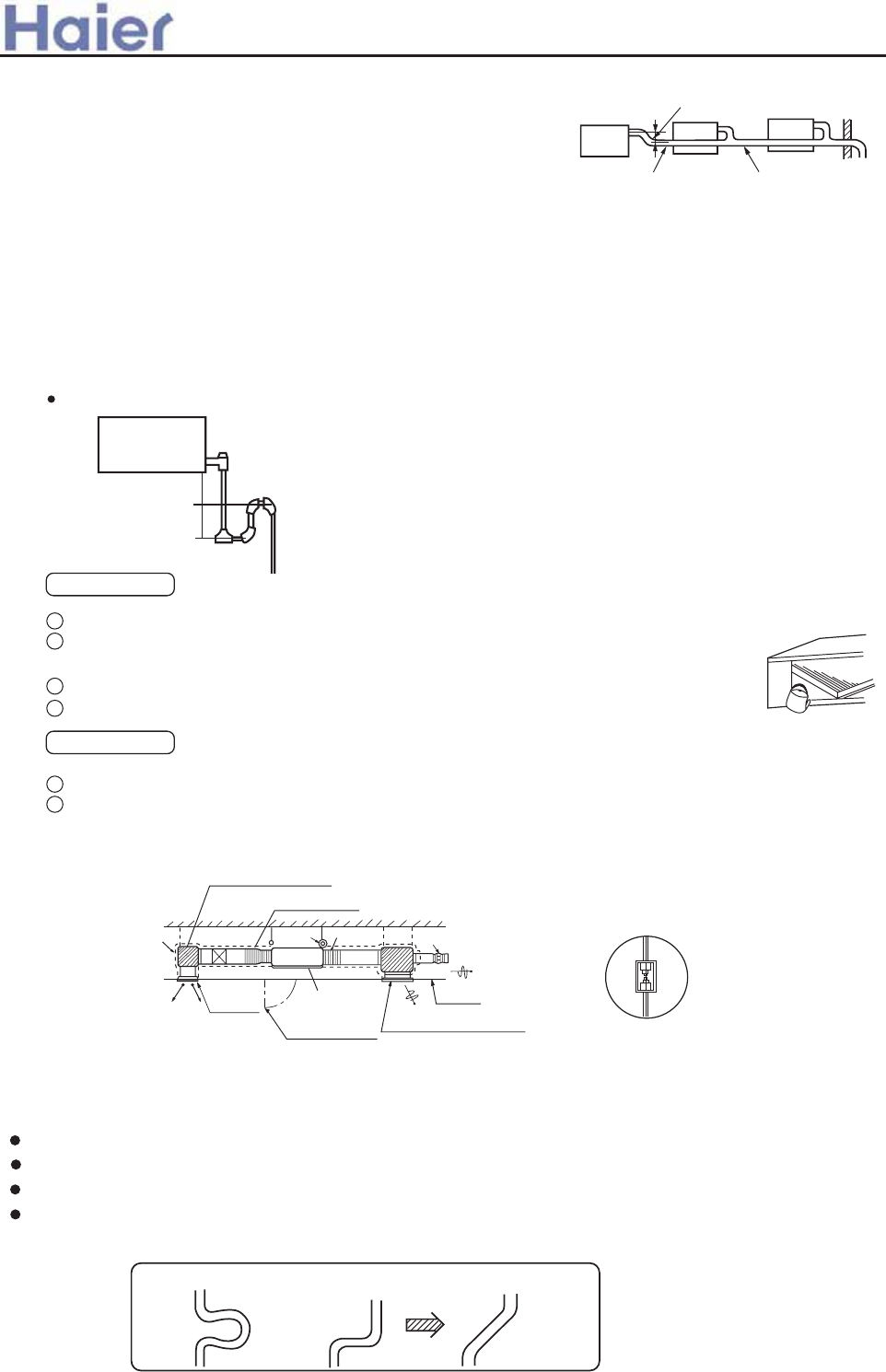
Drainage Test
Conduct a drainage test after completion of the electrical work.
During the trial, make sure that drain flows properly through the piping and that
no water leaks from connections.
In case of a new building, conduct the test before it is furnished with the ceiling.
Be sure to conduct this test even when the unit is installed in the heating season.
Procedures
Supply about 1000 cc of water to the unit through the air outlet using a feed water pump.
Check the drain while cooling operation.
(g)
1
2
3
4
1
2
VP 30
Secure the elevation as high as possible
(approx. 100 mm)
A downhill grade of
1/100 or more
When constructing drain piping for several units,
position the common pipe about 100 mm below
the drain outlet of each unit as shown in the sketch.
Use VP-30(11/4") or thicker pipe for this purpose.
(d)
(e) The stiff PVC pipe put indoor side should be heat insulated.
(f) Avoid putting the outlet of drain hose in the places with irritant gas generated. Do not insert the drain
hose directly into drainage, where the gas with sulfur may be generated.
Backwater bend
Because the drain spout is at the position, which negative pressure may occur. So with the rise of
water level in the drain pan, water leakage may occur. In order to prevent water leakage, we designed a
backwater bend.
The structure of backwater bend should be able to be cleaned. As the below figure shown, use T
type joint. The backwater bend is set near the air conditioner.
As figure shown, set a backwater bend in the middle of drain hose.
H
1
H
2
H1=100mm or the static pressure of air sending motor
H2=1/2H1 (or between 50~100mm)
6. Installation of air suction and discharging duct
A
Insulation
muffler cavity (air sending)
Sacking joint
Air volume adjuster
Air outlet
Enlarging chart of
profile chart A
Vibration resistance hook
Checking meatus
Air conditioner
main unit Ceiling
Air suction grille with air filter
Please consult the after-sales service worker of Haier Air Conditioner for the choosing and installation
of suction inlet, suction duct, discharging outlet and discharging duct. Calculating the design drawing
and outer static pressure, and choose the discharging duct with proper length and shape.
Good exampleBad exampleBad example
The length difference among every duct is limited below 2:1.
Reduce the length of duct as possible as can.
Reduce the amount of bend as possible as can.
Use heat insulation material to bind and seal the part connecting main unit and the flare part of air
discharging duct. Perform duct installation work, before the ceiling fit.
>a__WcU[S^<[c>a`V[e[a`Wc
-104-
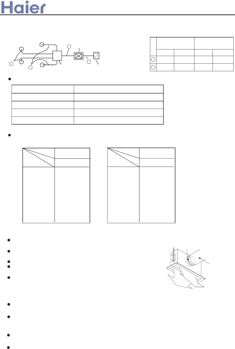
The calculation of duct resistance (the simple calculation is as follow table)
Straight part
Bend part
Air out part
Static pressure box
Air inlet grille (with air filter)
Calculate as per 1m length 1Pa, 1Pa/m
Each bend takes as a3~4m long straight duct
Calculate as 25Pa
Calculate as 50Pa/each
Calculate as 40Pa/each
7. Calculation method of the dimension of the simple quadrate air duct
Presuming the unit length friction impedance of the duct is 1Pa/m, when the dimension of one side of the air duct
is fixed as 250mm, as shown below:
Note:1Pa/m=0.1mmAg/m
The chosen chart of simple duct
m
3
/h(m
3
/n)
100
200
300
400
500
600(10)
800
1,000
1,200(20)
250 x 60
(mmxmm)
250 x 90
250 x 120
250 x 140
250 x 170
250 x 190
250 x 230
250 x 270
250 x 310
Shape
Item
Air volume
Square duct
Dimension
m
3
/h(m
3
/n)
1,400
1,600
1,800(30)
2000
2400
3,000(50)
3,500
4,000
4,500
5,000
5,500
6,000(100)
(mmxmm)
250 x 350
250 x 390
250 x 430
250 x 470
250 x 560
250 x 650
250 x 740
250 x 830
250 x 920
250 x 1000
250 x 1090
250 x 1180
Shape
Item
Air volume
Square duct
Dimension
Static pressure box
Air conditioner
Equipped with
air filter (bought)
B
A
A
A
8. The attentive matters in installation of air suction and discharging duct
Recommend to use anti-frost and sound-absorbing
duct. (locally bought)
The duct installation work should be finished before the
fitment of ceiling.
The duct must be heat insulated.
The specific air-discharging outlet should be installed at
the place where the airflow can be reasonably distributed.
The surface should leave a checking meatus for checking
and maintenance.
9. The examples of improper installation
Do not use air in duct and take the ceiling inner side instead. The result is because of the irregular
outer air mass, strong wind and sunshine, the humidity is increased.
There may be water drop on the outside of duct. For cement and other new constructions, even if not
taking ceiling inner side as duct, the humidity will also be so high. At this time, use glass fiber
to perform heat preservation to the whole. (use iron net to bind the glass fiber)
Affected by the capacity of air discharging fan, the strong wind in the outer duct and wind direction,
when unit air sending volume exceeds the limit, the discharged water of heat exchanger will overflow,
leading to water leakage.
Air Air
Duct
Special air discharging outlet
Use screw bolt to fix
Maybe exceeding the unit operation limit (for example: when indoor dry bulb temperature is 35degree,
web bulb temperature is 24degree), it may lead to overload of compressor.
>a__WcU[S^<[c>a`V[e[a`Wc
600m
3
/h
(10m
3
/min)
Duct
(mmxmm)
2400m
3
/h
(40m
3
/min) 250x560
250x190
Air volume
B
A
300m
3
/h
(5m
3
/min)
Duct
(mmxmm)
1200m
3
/h
(20m
3
/min) 250x310
250x120
Air volume
AD362AHEAA
AD482AHEAA
AD602AHEAA AD282AHEAA
-105-
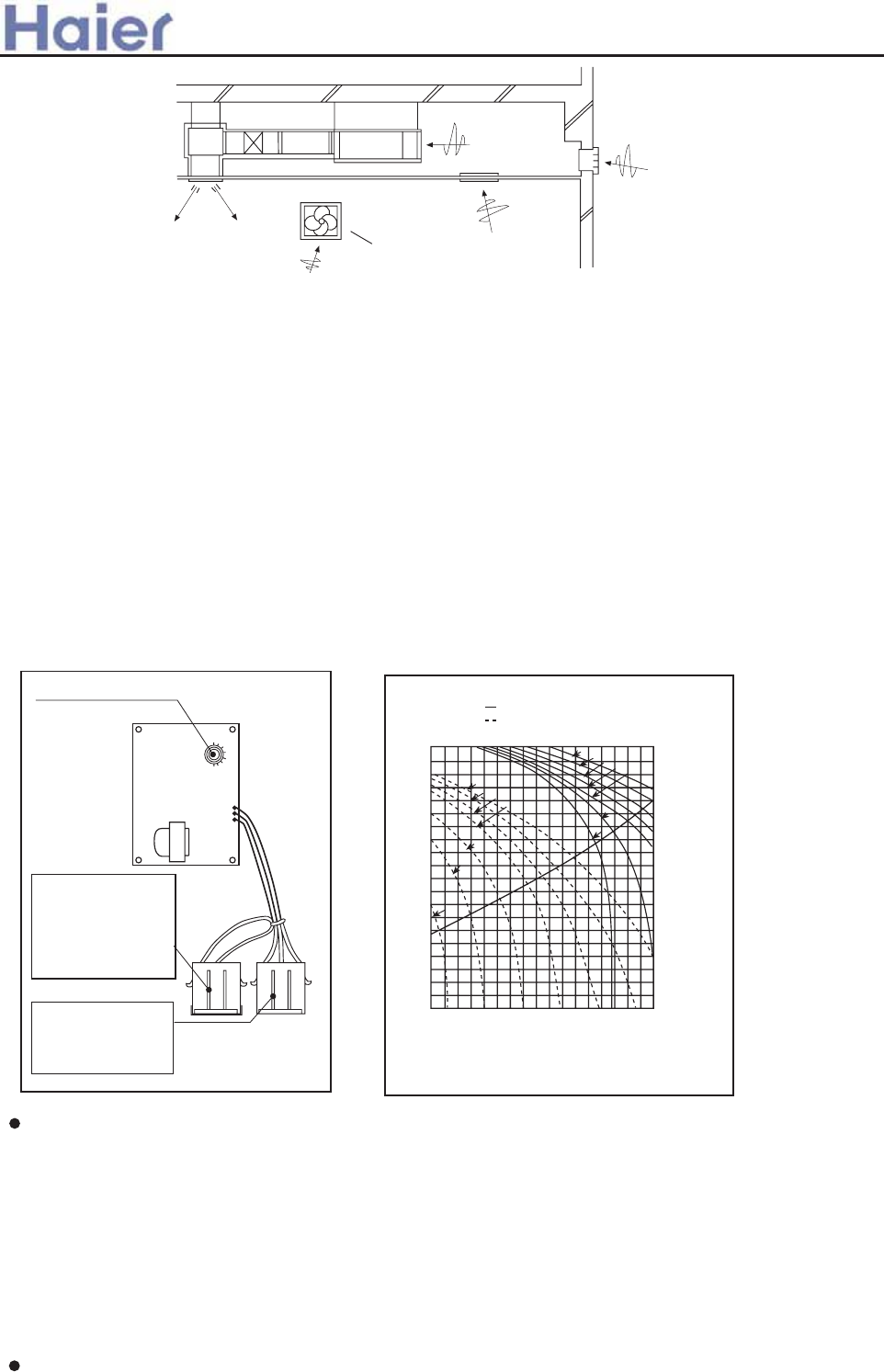
Air discharging fan
Improper example
10. The operation method of fan controller
Through the fan controller switch in the electric box, the air volume of this unit can be continuously adjusted.
It is unnecessary to adjust air volume through the duct side wind level (unit outside static adjustment).
The air volume set should be in the operation air volume range.
Figure I shows the position of fan controller in the electric box and operation method.
After finishing the electric work, perform test run. According to the main points in Figure II making the chosen
switch No. accordant. And confirm if it reaches the needed air volume.
Note:
1) When operating the fan controller, it is possible to touch the electric charging part, so do cut off the
power supply.
2) Do not set the dial at the position less than 1.
3) The figure circled in Figure II indicate the capacity number of fan controller. The non-listed capacity
number may exceed the permitted operation capacity range, so it is impossible to operate.
4) When delivering from factory, the capacity number of fan controller is set at No.5.
Rotate this switch
(capacity number
setting:
No. 1 ~ No. 8)
Once the fan controller
has trouble, this linker
can perform emergency
assistant control. When
this linker is connected
to the linker from the
PCB, it can operate with
total load.
When this linker is
connected to the linker
from the PCB, through
the fan speed adjustment
panel to adjust speed.
High Condition of standard air volume
Low (air volume 100Pa)
Outer static pressure Pa
Example of
duct
Lower limit Upper limit
Standard air volume
(m
3
/min)
The example of the method of choosing capacity number:
1) If the unit is in high-speed operation, needing take outer static pressure is 180Pa in capacity air volume
34m3/min as working condition point, according to Figure II The characteristic chart of air volume, the
capacity number of fan controller is No. 2.
2) If the unit is in low speed operation, needing take outer static pressure is 60Pa in capacity air volume
32m3/min as working condition point, according to Figure II The characteristic chart of air volume, the
capacity number of fan controller is No. 4.
11. Refrigerant pipe
[The air side pipe, liquid side pipe must be faithfully heat insulated, if no heat insulation, it may cause
water leakage.]
The outdoor unit has been charged with refrigerant.
200
150
100
50
026 30 34 35 40 43
*
*
*
*
*
*
*
*
**
*
*
*
*
Figure 1 Figure 2
>a__WcU[S^<[c>a`V[e[a`Wc
-106-
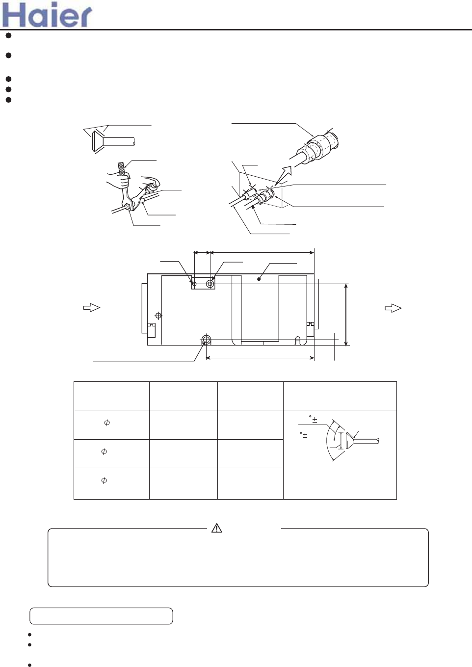
5. Electric wiring
(1) Selection of size of power supply and interconnecting wires.
Precautions for Electric wiring
Electric wiring work should be conducted only by authorized personnel.
Do not connect more than three wires to the terminal block. Always use round type
crimped terminal lugs with insulated grip on the ends of the wires.
Use copper conductor only.
Select wire sizes and circuit protection from table below. (This table shows 20 m length wires with less
than 2% voltage drop.)
When connect the pipe to the unit or dismantling the pipe from the unit, please follow the figure shown,
use spanner and torque spanner together.
When connect cone nut, the inner side and outside of cone nut should paste with refrigerant oil. Use
hand to twist 3-4 rings, then fasten with spanner.
Referring to Table I to confirm the fasten torque. (too tight may damage nut leading to leakage)
Check if the connection pipe leaks, then do heat insulation treatment, as below figure shown.
Only use seal cushion to bind the joint part of air pipe and heat insulation parts.
9.52 12.0~12.4
18.6~19.0
3270~3990 N.cm
(333~407 kgf.cm)
6180~7540 N.cm
(630~770 kgf.cm)
(mm)
Specification of pipe
15.88
Tighten torque Cone
Cone dimension
A (mm)
R0.4~0.8
A
90 0.5
45 2
22.9~23.3
9720~11860 N.cm
(990~1210 kgf.cm)
19.05
Liquid pipe Gas pipe Electric box
Upper
Air inlet Air outlet
Down side
Drain hose connection hole
VP25 PVC pipe
310
30
530
80 510
Paste the refrigerant oil here
Torque spanner
Spanner
Pipe joint
Cone nut
Middle size seal cushion (accessory)
(Use seal cushion to
bind the pipe joint)
Clamp
Heat insulation (accessory)
(for liquid pipe)
(for gas pipe)
Heat insulation (accessory)
Gas pipe
Liquid pipe
WARNING
DANGER OF BODILY INJURY OR DEATH
TURN OFF ELECTRIC POWER AT CIRCUIT BREAKER OR POWER SOURCE BEFORE
MAKING ANY ELECTRIC CONNECTIONS. GROUND CONNECTIONS MUST BE
COMPLETED BEFORE MAKING LINE VOLTAGE CONNECTIONS.
>a__WcU[S^<[c>a`V[e[a`Wc
-107-
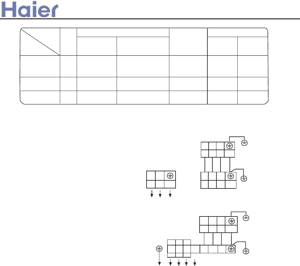
>a__WcU[S^<[c>a`V[e[a`Wc
(2) Wiring connection
Make wiring to supply power to the outdoor unit, so that the power for the indoor unit is supplied by
terminals.
Item
Model Phase
3
Switch breaker
(A)
Circuit breaker
Overcurrent
protector
Power source
wire size
(minimum)
(mm2)
30 20 2.5
Switch
breaker(A)
Earth leakage breaker
Leak
current(mA)
30 30
AD282AHEAA
AD362AHEAA
AD282AHEAA
AD362AHEAA
1PH,220-230V~,50Hz
POWER SUPPLY:
INDOOR UNIT
TERMINAL BLOCK
L N
1 2 3
1 2 3
3040 30 6.0 40
OUTDOOR UNIT
TERMINAL BLOCK
INDOOR UNIT
TERMINAL BLOCK
POWER SUPPLY:
380-400V, 3N~,50Hz
R S T
N 1 2 3
1 2 3
AD282AHEAA
AD362AHEAA
330 20 4.0 30 30
1
OUTDOOR UNIT
TERMINAL BLOCK
AD482AHEAA
AD602AHEAA
AD482AHEAA
AD602AHEAA
AD362AHERA
Y/G
Y/G
Y/G
Y/G
AD282AHEAA
AD362AHEAA
-108-
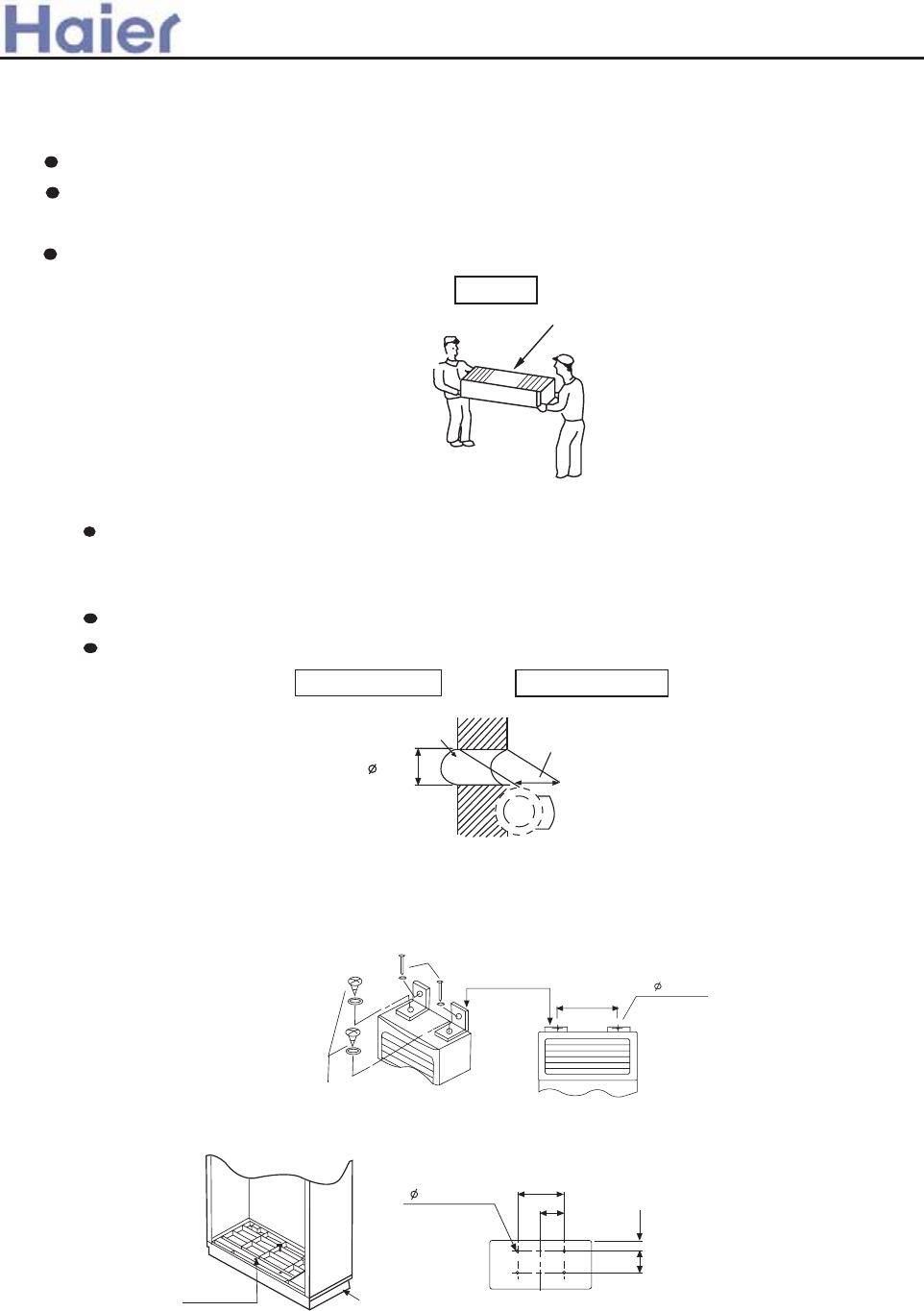
A\fc_Tl bY j[b_X ha\g
Oel gb Ue\aZ g[X cTV^XW ha\g gb g[X \afgT__Tg\ba c_TVX1
R[Xa \g \f aXVXffTel gb hacTV^ g[X ha\g/ UX VTeXYh_ abg gb WT`TZX g[X ha\g1 ReTc \g j\g[
al_ba XgV1
>YgXe hacTV^\aZ/ UX fheX gb c_TVX g[X ha\g j\g[ g[X Yebag f\WX gb UX hc1
JbgX= R[Xa WX_\iXe\aZ/ Wba,g [b_W c_Tfg\V
cTegf fhV[ Tf \a_Xg be bhg_Xg Ze\__ XgV1
AX_\iXel
CTV\aZ hc
C\k\aZ bY g[X ha\g
RT__ [b_X f[bh_W UX WXV\WXW TVVbeW\aZ gb \afgT__g\ba c_TVX TaW c\c\aZ W\eXVg\ba1 -eXYXe
gb \afgT__Tg\ba WeTj\aZf.
IT^\aZ T [b_X
Ae\__ T [b_X bY :3`` W\T1 j\g[ T _\gg_X f_bcX gbjTeWf bhgf\WX1
FafgT__ c\c\aZ [b_X VbiXe TaW fXT_ \g j\g[ chggl TYgXe \afgT__Tg\ba1
Lbf\g\ba bY g[X jT__ [b_X
FJAKKM NFAB
KPOAKKM NFAB
jT__ [b_X jT__ g[\V^aXff
- @ebff fXVg\ba bY jT__ [b_X .
:3``
>a__WcU[S^<[c>a`V[e[a`Wc
With the unit set up vertically,fix the fitting metal to the unit with screws, then fix the
fitting metal to the wall with cement nail and washer, as shown below:
Moreover, if want to fix the unit more firmly, you should fix the bottom panel to the
ground with concrete bolts,as shown below:
330 2- 10 hole
Screw
Fitting metal
Cement nail
Fitting hole Bottom Panel
4- 14 hole 30 depth 260
130
79
202
(202) (79)
*8<=-66-=598 92 -8=5r2-66 :6-=1|
C\k g[X Tag\0YT__ c_TgX gb g[X jT__ j\g[ fVeXjf fb g[Tg g[XeX \f ab V_XTeTaVX UXgjXXa g[X`1
R\g[ g[X ha\g fXg hc iXeg\VT__l/ Y\k g[X Tag\0YT__ c_TgX gb g[X ha\g j\g[ fVeXjf j[\_X `T^\aZ Ta
TW]hfg`Xag Tg g[X _baZ cbeg\ba bY g[X [b_X fb g[Tg g[XeX \f ab V_XTeTaVX UXgjXXa g[X hccXe
6.7 Cabinet indoor unit (AP42-AP60)
-109-
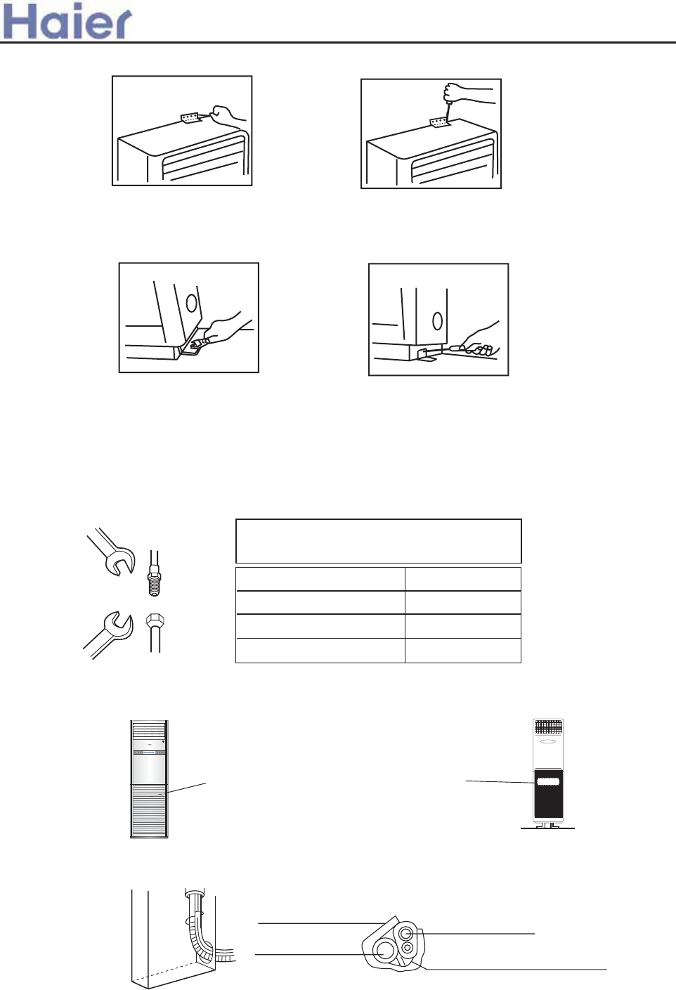
fheYTVX TaW g[X Tag\0YT__ c_TgX1
*8<=-66-=598 92 +r<4-:10 71=-6
>YgXe VbaY\e`\aZ g[Tg g[X ha\g [Tf UXXa fXg hc iXeg\VT__l gb g[X Y_bbe/ Y\k \g gb g[X Y_bbe j\g[ Ub_g1
,5:583 /9881/=598
@baaXVg\aZ `Xg[bW
>cc_l eXYe\ZXeTag b\_ Tg [T_Y ha\ba TaW Y_TeX ahg1
Ob UXaW T c\cX/ Z\iX g[X ebhaWaXff Tf _TeZX Tf cbff\U_X abg gb VeTf[ g[X c\cX1
R[Xa VbaaXVg\aZ c\cX/ [b_W g[X c\cX VXageX gb VXageX g[Xa fVeXj ahg ba Ul [TaW/eXYXe gb C\Z1
?X VTeXYh_ abg gb _Xg fhaWe\Xf/ fhV[ Tf fTaWf XagXe g[X c\cX1
41
CbeVXW YTfgXa\aZ j\g[bhg VXagXe\aZ `Tl
WT`TZX g[X g[eXTWf TaW VThfX T ZTf _XT^TZX1
L\cX W\T CTfgXa\aZ gbedhX
H\dh\W c\cX <185``-62;+.
DTf c\cX 481;;``-82;+.
5<17J1`
<;13J1`
DTf c\cX 4<138``-627+. 44:1:J1`
51 L\c\aZ VbaaXVg\ba bY \aWbbe ha\g
>eeTaZX`Xag bY c\c\aZ TaW WeT\aTZX c\cX
>YgXe bcXa\aZ \a_Xg Ze\__/ lbh j\__ fXX T Vbageb_
Ubk Tf f[bja \a g[X C\Z1
MX`biX g[X VbiXe UXYbeX j\e\aZ jbe^1
>a__WcU[S^<[c>a`V[e[a`Wc
˜£˚‰•¸
¿“/„
˛´¶¨+ ‰¡¿
˛´¶¨-
C\k gb g[X ha\g j\g[ fVeXjf fb g[Tg g[XeX \f ab V_XTeTaVX UXgjXXa g[X Tag\0YT__ c_TgX TaW g[X ha\g1
@hg TjTl/ j\g[ T [T``Xe be T fTj/ g[X _\W Ybe c\c\aZ TVVbeW\aZ gb c\c\aZ W\eXVg\ba1
Fafh_Tg\ba `TgXe\T_
@bccXe ghUX
AeT\a [bfX
@baaXVg\aZ X_XVge\V VTU_X
Ybe \aWbbe TaW bhgWbbe ha\g
>VVbeW\aZ gb g[X c\c\aZ `Xg[bW/ VbaaXVg g[X c\c\aZ ba \aWbbe ha\g j\g[ ha\ba bY VbaaXVg\aZ c\cX1
-110-
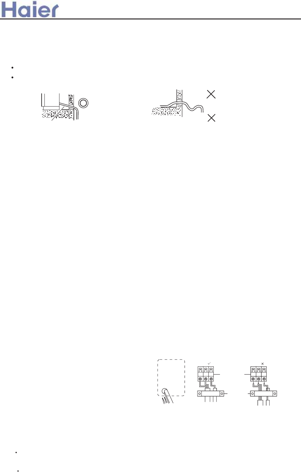
>eeTaZX g[X c\c\aZ Tf cXe g[X jT__ [b_X TaW U\aW WeT\a [bfX VbaaXVg\aZ X_XVge\V VTU_X TaW gbZXg[Xe
j\g[ cb_lXg[l_XaX gTcX1
FafXeg g[X UbhaW c\c\aZ VbaaXVg\aZ X_XVge\V VTU_X TaW WeT\a [bfX g[ebhZ[ jT__ [b_X gb VbaaXVg j\g[ bhgWbbe ha\g1
>eeTaZX`Xag bY WeT\a [bfX
AeT\a [bfX f[T__ UX c_TVXW \a haWXe c_TVX1
O[XeX f[bh_W UX T f_bcX j[Xa TeeTaZX WeT\a [bfX1 >ib\W hc TaW Wbja jTiXf \a WeT\a [bfX1
FaWbbe ha\g
N_bcX DbbW
Pc
Abja ?TW
FY [h`\W\gl \f [\Z[/ WeT\a c\cX- XfcXV\T__l \a ebb` TaW \aWbbe ha\g . `hfg UX VbiXeXW
j\g[ \afh_Tg\ba `TgXe\T_1
@baaXVg g[X VbaaXVg\aZ c\cX TaW \a_Xg TaW bhg_Xg _\dh\W c\cX TVVbeW\aZ gb g[X c\c\aZ `Xg[bW1
R[Xa c\c\aZ \f _baZXe g[Ta 8 `/ V[TeZX TWW\g\baT_ eXYe\ZXeTag Tf cXe 98Z2`1
ws,>;3583 71=490
A\fV[TeZX g[X T\e bhg bY g[X \aWbbe ha\g TaW g[X eXYe\ZXeTag c\cX Ul iTVhh`\m\aZ
-5. PaWXe g[X VbaW\g\ba bY g[X Vb`c_XgX V_bfX bY g[X \aWbbe TaW bhgWbbe iT_iX VXagXe -Ubg[ _\dh\W TaW ZTf
f\WX./W\f`bhag g[X eXcT\e iT_iX VTc1QTVhh`\m\aZ g[ebhZ[ g[X V[TeZX `bhg[ bY g[X eXcT\e iT_iX1
-6. >YgXe iTVhh`\m\aZ YTfgXa g[X eXcT\e iT_iX/TaW W\f`bhag g[X VTc bY g[X U\Z TaW f`T__ fgbc iT_iX/g[Xa
_bbfXa g[X fgbc iT_iX VXagXe Vb`c_XgX_l TaW YTfgXa g[X U\Z TaW f`T__ fgbc iT_iX1
xs~@=;- /4-;3583 -79>8= 92 =41 ;12;531;-8=
vs ,5:583 /9881/=598 92 9>=099; >85=
>a__WcU[S^<[c>a`V[e[a`Wc
c\c\aZ
~61/=;5/ ?5;583
JbgX=
B_XVge\V j\e\aZ `hfg UX WbaX Ul dhT_\Y\XW cXefba1
PfX VbccXe j\eX ba_l/ g[X cTeT`XgXe bY VbaaXVg\aZ VTU_X \f E3:MJ0C 7D 31:8``51
FafXeg g[X VTU_X Yeb` bhgf\WX g[X jT__ [b_X j[XeX c\c\aZ T_eXTWl Xk\fg1
Lh__ \g bhg Yeb` Yebag1
HbbfXa gXe`\aT_ fVeXjf TaW \afXeg VTU_X XaW Yh__l \agb gXe`\aT_ U_bV^/ g[Xa g\Z[gXa \g1
Lh__ g[X VTU_X ZXag_l gb `T^X fheX \g \f g\Z[g1
O[X cbjXe VTU_X f[bh_W UX biXe 8D518``5/ g[X cbjXe VTU_X \f fX_Y0cebi\WXW1
O[X cbjXe fhcc_l VbaaXVgf Yeb` g[X bhgWbbe ha\g1
MXc_TVX VbiXe TYgXe j\e\aZ1
R\e\aZ bY bhgWbbe ha\g
FafXeg g[X VTU_X Yeb` \af\WX g[X jT__ [b_X
j[XeX c\c\aZ T_eXTWl Xk\fgf1
Lh__ \g bhg Yeb` Yebag1
HbbfX gXe`\aT_ fVeXj TaW \afXeg VTU_X XaW Yh__l
\agb gXe`\aT_ U_bV^/ g[Xa g\Z[gXa \g1
Lh__ g[X VTU_X ZXag_l gb `T^X fheX \g \f g\Z[g1
MXc_TVX VbiXe TYgXe j\e\aZ1
JbgX=
R[Xa VbaaXVg\aZ \aWbbe TaW bhgWbbe j\eX/ V[XV^ g[X ah`UXe ba \aWbbe TaW bhgWbbe
OXe`\aT_f bY fT`X ah`UXe TaW fT`X Vb_be f[T__ UX VbaaXVgXW Ul g[X fT`X j\eX1
FaVbeeXVg j\e\aZ `Tl WT`TZX T\e VbaW\g\baXe,f Vbageb__Xe be VThfX bcXeTg\ba YT\_heX1
KG JK
gXe`\aT_ U_bV^
gTU_X V_T`c
gXe`\aT_ U_bV^f1
R\e\aZ bY \aWbbe ha\g
-4. CTfgXa T__ g[X ahgf bY g[X \aWbbe TaW bhgWbbe c\cXf gb `T^X g[XfX cTegf bhg bY _XT^TZX1
-111-
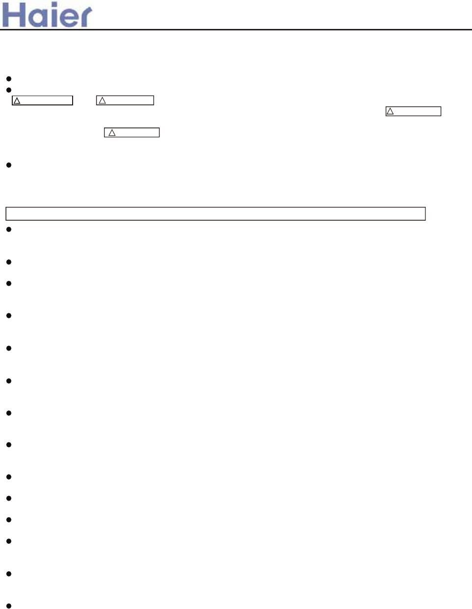
>a__WcU[S^<[c>a`V[e[a`Wc
Please read these "Safety Precautions" first then accurately execute the installation work.
The precautionary points indicated herein are divided under two headings:
WARNING and CAUTION those points which are related to the strong possibility of an
installation done in error resulting in death or serious injury are listed in the WARNING
section. However, there is also a possibility of serious consequences in relationship to the
points listed in the CAUTION section as well.
observe all that is mentioned.
After completing the installation, along with confirming that no abnormalities were seen
from the operation tests, please explain operating methods as well as maintenance methods to
the user of this equipment, based on the owner's manual.
Moreover, ask the customer to keep this sheet together with the owner's manual.
WARNING
Please entrust installation to either the company which sold you the equipment or to a
professional contractor. Defects from improper installations can be the cause of water leakage
electric shocks and fires.
Execute the installation accurately, based on following the installation manual. Again improper
installations can result in water leakage, electric shocks and fires.
Please install your air conditioner on a wall or any place which can holder the weight of the
air conditioner. And it cannot be installed on a non-professional metal structure (such as a
burglary-resisting net). Otherwise injury would occur due to a falling of the unit.
Execute the prescribed installation construction to prepare for earthquakes and the strong airs
of typhoons and hurricanes, etc. Improper installations can result in accidents due to a violent
falling over of the unit.
Wiring shall be done with the specified cable and the connection shall be firm and reliable.
And the terminal connector shall be fixed firmly and reliably not to let external force exercise
on the cables. Any improper connection or fixing would cause heat, fire, and other accidents.
Wiring shall be done in a correct shape not to make any section rise upward, and accurately
install the air conditioner. The cable shall not be clamped by the lid or outer plate. Any
improper installation would lead to fire, heat, or other accidents.
When setting up or moving the location of the air conditioner, do not mix air etc, or anything
other than the designated refrigerant (R407C) within the refrigeration cycle, for such mixing
would result in rupture and injury caused by abnormal high pressure.
Always use accessory parts and authorized parts for installation construction. Using parts not
authorized by this company can result in water leakage, electric shock, fire and refrigerant
leakage.
The drain pipe must not be placed or connected into the sewage tank where harmful gas such
as sulphurous gas and etc would exist, otherwise the harmful gas would enter the room.
During installation, if the refrigerant is leaked, please immediately take measures of
ventilation, otherwise a harmful gas would be generated whenever the refrigerant meets fire.
After installation, please ensure that the refrigerant is not leaked, because the leakage of
refrigerant would produce a harmful gas if it meets fire or heating stoves.
Don't install the air conditioner where a flammable gas would be probably produced,
otherwise in case the flammable gas is leaked and exists around the unit, fire would be
caused.
For the drain pipe, follow the installation manual to insure that it allows proper drainage and
thermally insulate it to prevent condensation. Inadequate plumbing can result in water
leakage and water damage to interior items.
The refrigerant gas pipe and liquid pipe shall all be thermally insulated to preserve the
temperature. Any improper insulation would make the unit moist and the water would drop
onto the floor or wet the indoor items.
INSTRUCTIONS TO INSTALLATION
6.8 Wall mounted indoor unit (AS182AVERA)
In either case, important safety related information is indicated, so by all means, properly
-112-
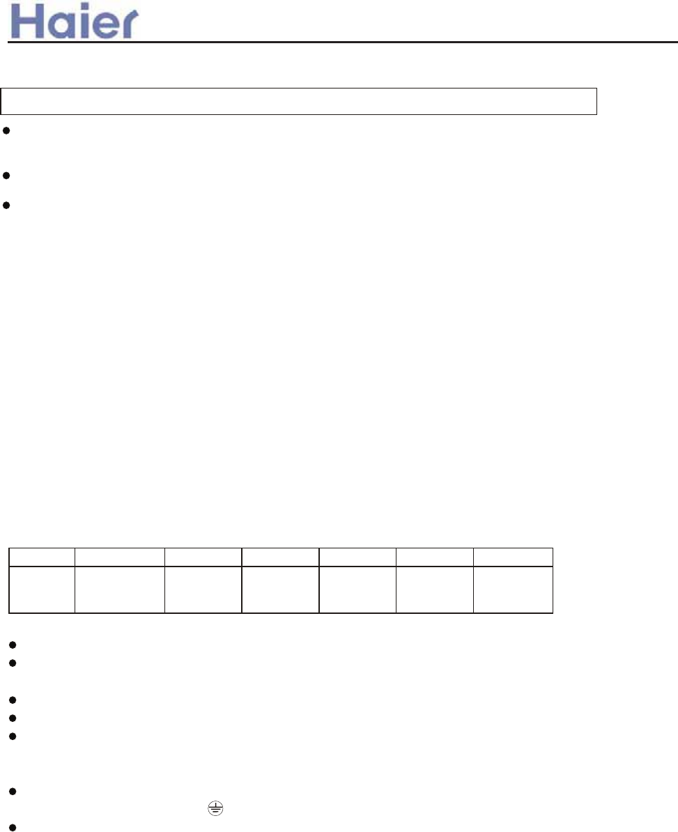
>a__WcU[S^<[c>a`V[e[a`Wc
PRECAUTION
Execute proper grounding. Do not connect the earth wire to a gas pipe, water pipe, lightening
rod, or a telephone ground wire.
Improper placement of earth wires can result in electric shock.
An electric leakage breaker must be installed, otherwise electric shock or other accidents
would occur.
After completion of the installation, the air conditioner shall be electrified to check for
electric leakage.
Preparation for installation
Installation Tools
1. Screw Driver (slotted head, cross head, triangle)
2. Steel Saw
3. 60mm Drill
4. Inner Hexagon Spanner
5. Shifting Spanner
6. Spanner
7. Pipe Cutter
8. Pipe Expander
9. Knives
10. Clippers
11. Leakage Checker or Soap Liquid
12. Measuring Tape
13. Scraper or File
14. Refrigeration Oil
Self-contained Accessories
Electrical Requirements
Power supply voltage: Single Phase 1PH, 220-230V~, 50Hz.
A specialized power supply wire, which shall be installed by a competent person as per the
rules of the national standard.
Power supply must be grounded effectively.
An electric leakage breaker shall be installed.
Layout of power supply wiring shall be Y connection. If the power supply wire is damaged, it
must be replaced by the manufacturer or its service center or professional person (the power
supply wire shall be self-contained).
For connection of the power supply plug, L shall be connected with the live wire, N shall be
connected with neutral line, shall be connected with earth wire.
Power supply wire parameters:H05RN-F,3 G(1.0-1.5)mm ;
Signal wire parameters:H05RN-F,2 (0.75-1.5)mm . (User shall self-provide signal wire )
Name of
Parts
No. A B C D E F
Non-adhesive
Tape
Adhesive
tape
Connecting
Hose
Gypsum
powder
Drain hoseHeat
insulation
material
2
2
X
INSTRUCTIONS TO INSTALLATION
Note:The signal wire and connection wire should be provided by oneself.
The signal wire must be shielded wire
-113-
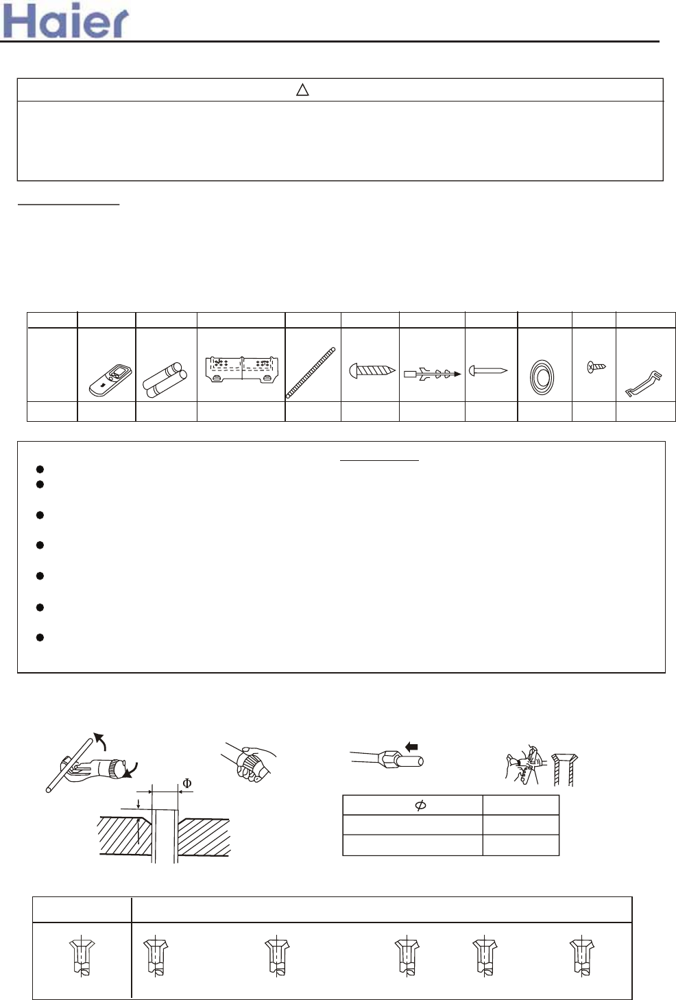
>a__WcU[S^<[c>a`V[e[a`Wc
Hose Expander
A
Expansion Size
Hose dia. Size (mm)A
0.8-1.5
1.0-2.0
6.35 mm(1/4)
12.7 mm(1/2)
WARNING
BE SURE TO READ THESE INSTRUCTIONS CAREFULLY BEFORE BEGINNING INSTALLATION. FAILURE TO
FOLLOW THESE INSTRUCTIONS COULD CAUSE SERIOUS INJURY OR DEATH, EQUIPMENT MALFUNCTION
AND/OR PROPERTY DAMAGE.
BE SURE TO READ INSTALLATION MANUAL FOR INDOOR UNIT WITH THIS MANUAL.
1.Accessories
Confirm accessories shown below are attached in the bag with this Installation manual.
Accessories Delivered with Your Air Conditioner
Please check if your unit is delivered with the following accessories.
x
4 25 screw Expansion
bushing
Cement
steel nail
Piping hole
cover
Screw Plastic
supporting
plate
10987
81 2
1
66
6
5
Drain hose
Mounting plate
Batteries
Remote
controller
12 3 4
1121
Name
and
shape
No.
Qty
!
INSTRUCTIONS TO INSTALLATION
Indoor Unit
Install the indoor unit where the weight of the unit can be supported.
Install the indoor unit where the heat source and steam source are not close and the unit inlet
and outlet are not blocked.
Install the indoor unit where the drainage is easy and the outdoor unit can be easily
connected.
Install the indoor unit where its cold air and hot air can be easily sent to all the comers of the
room.
Install the indoor unit where the power socket is near and there is sufficient space around the
indoor unit.
Install the indoor unit where there is no T.V set, radio set, and wireless appliance underneath,
and the sunlight lamp is over one meter away.
If the remote controller is installed on the wall, the indoor unit shall be ensured to receive the
signal while the sunlight lamp is on.
Method for Cutting and Expanding Pipes.
When the pipe is too long or the mouth is damaged, the pipe needs to cut or expanded.
1.cutting hose
Correct Not Correct
2.Removing burr 3.Put on nut 4.Expand Hose
cracks on expanded mouth burr incomplete too longTilting
-114-
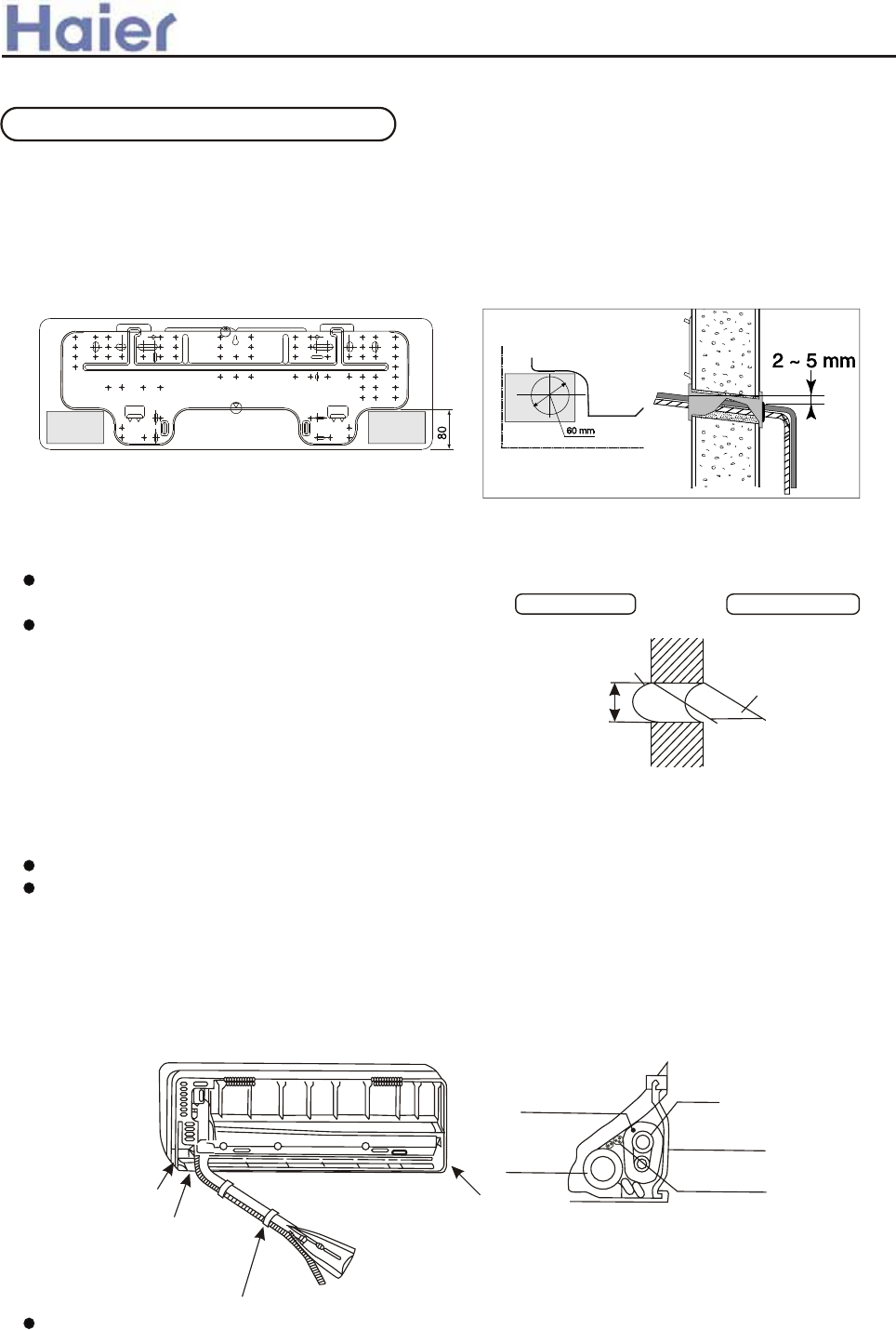
>a__WcU[S^<[c>a`V[e[a`Wc
When the mounting plate is first fixed
1. Carry out, based on the neighboring pillars or lintels, a proper leveling for the plate
to be fixed against the wall, then temporarily fasten the plate with one steel nail.
2. Make sure once more the proper level of the plate, by hanging a thread with a
weight from the central top of the plate, then fasten securely the plate with the
attachment steel nail.
3. Making a Hole on the wall and Fitting the piping Hole cover
Make a hole of 60mm in diameter,
slightly descending to outside the wall.
Install piping hole cover and seal it
off with putty after installation.
4. Drawing of pipe
Rear piping
Draw pipes and the drain hose, then fasten them with the adhesive tape.
Left Left-rear, piping
In case of left side piping, cut away, with a nipper, the lid for left piping.
In case of left-rear piping, bend the pipes according to the piping direction to the mark
of hole for left-rear piping which is marked on heat insulation materials.
a. Insert the drain hose into the dent of heat insulation materials of indoor unit.
b. Insert the indoor/outdoor electric cord from backside of indoor unit, and pull it out
on the front side, then connect them.
c. Coat the flaring seal face with refrigerant oil and connect pipes.
Cover the connection part with heat insulation materials closely, and make sure fixing
with adhesive tape.
Indoor/outdoor electric cord and drain hose must be bound with refrigerant piping
by protecting tape.
Indoor side Outdoor side
Wall hole Thickness
of wall
60mm
(Section of wall hole) Piping hole pipe
Indoor/Outdoor
Electric cable
Pipe supporting
plate
Heat insulation
material
Drain hose
Lid for left piping
Lid for right piping
Lid for under piping pipe
Fix with adhesive tape
Piping
INSTALLATION PROCEDURE
-115-
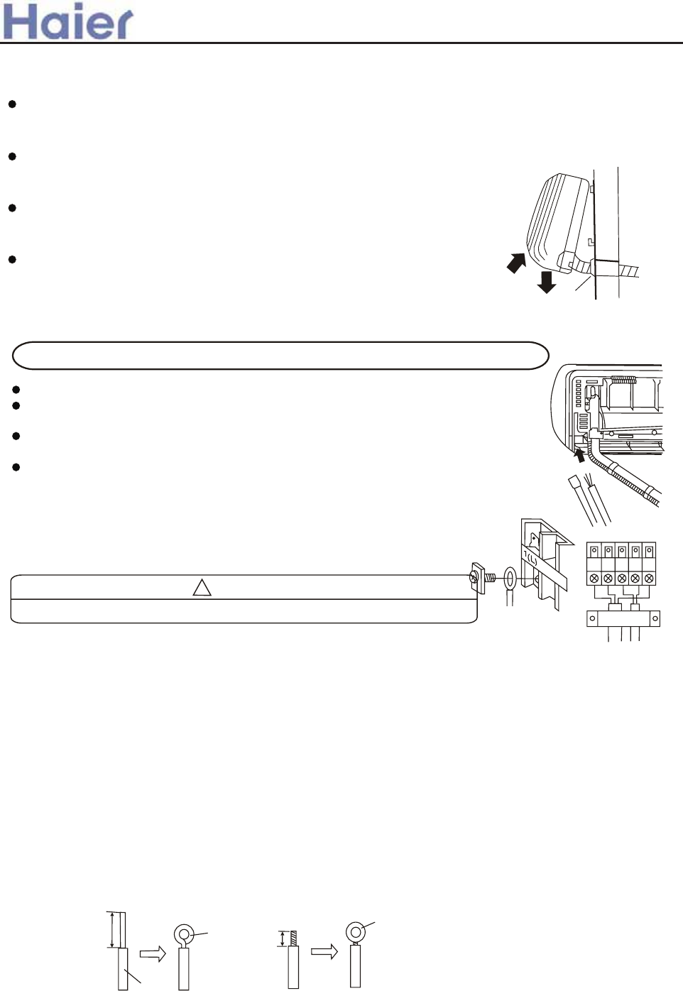
>a__WcU[S^<[c>a`V[e[a`Wc
Other direction piping
Cut away, with a nipper, the lid for piping according to the piping direction and then
bend the pipe according to the position of wall hole. When bending, be careful not
to crash pipes.
Connect beforehand the indoor/outdoor electric cable, and then pull out the
connected to the heat insulation of connecting part specially.
5.Fixing the indoor unit body
Hang surely the unit body onto the upper notches of the
mounting plate. Move the body from side to verify its
secure fixing.
In order to fix the body onto the mounting plate, hold up
the body aslant from the underside and then put it down
perpendicularly. Putty
INSTALLATION PROCEDURE
Insert the cord from the back side of the unit, then pull it out on the front side.
Loosen the screws and insert the cord ends fully into terminal block, then
tighten the screws.
Pull the cord slightly to make sure the cords have been properly inserted and
tightened.
After the cord connection, never fail to fasten the connected cord with the
wiring cover.
Note: when connecting the cord, confirm the
terminal number of indoor and outdoor units
carefully. If wiring is not correct, proper operation
can not be carried out and will cause defect.
(1) Cut the wire with a wire cutter or wire-cutting pliers, then strip the insulation to about 25mm of the exposed
solid wire.
(2) Using a screwdriver, remove the terminal screw (s) on the terminal board.
(3) Using pliers, bend the solid wire to form a loop suitable for the terminal screw.
(4) Shape the loop wire properly, place it on the terminal board and tighten securely with the terminal screw using
a screw driver.
(1) Cut the wire with a wire cutter or wire-cutting pliers, then strip the insulation to about 10mm of the exposed
strand wiring.
(2) Using a screwdriver, remove the terminal screw (s) on the terminal board.
(3) Using a round terminal fastener or pliers, securely clamp a round terminal to each stripped wire end.
(4) Position the round terminal wire, and replace and tighten the terminal screw using a screw driver.
ELECTRICAL WIRING
CAUTION
!
After connecting the piping, check the joints for gas leakage with gas leakage detector.
When connecting the cord before installing the indoor unit
HOW TO CONNECT WIRING TO THE TERMINALS
A. For solid core wiring (or F-cable)(Fig.17A)
B. For strand wiring (Fig.17B)
Fig. 17
A. Solid
Round
terminal
Loop
Insulation
Strip 25mm
Strip 10mm
After passing the connection cord and power cable through the
insulation tube, fasten it with the cord clamp, as shown in Fig.18
B. Strand wire
-116-
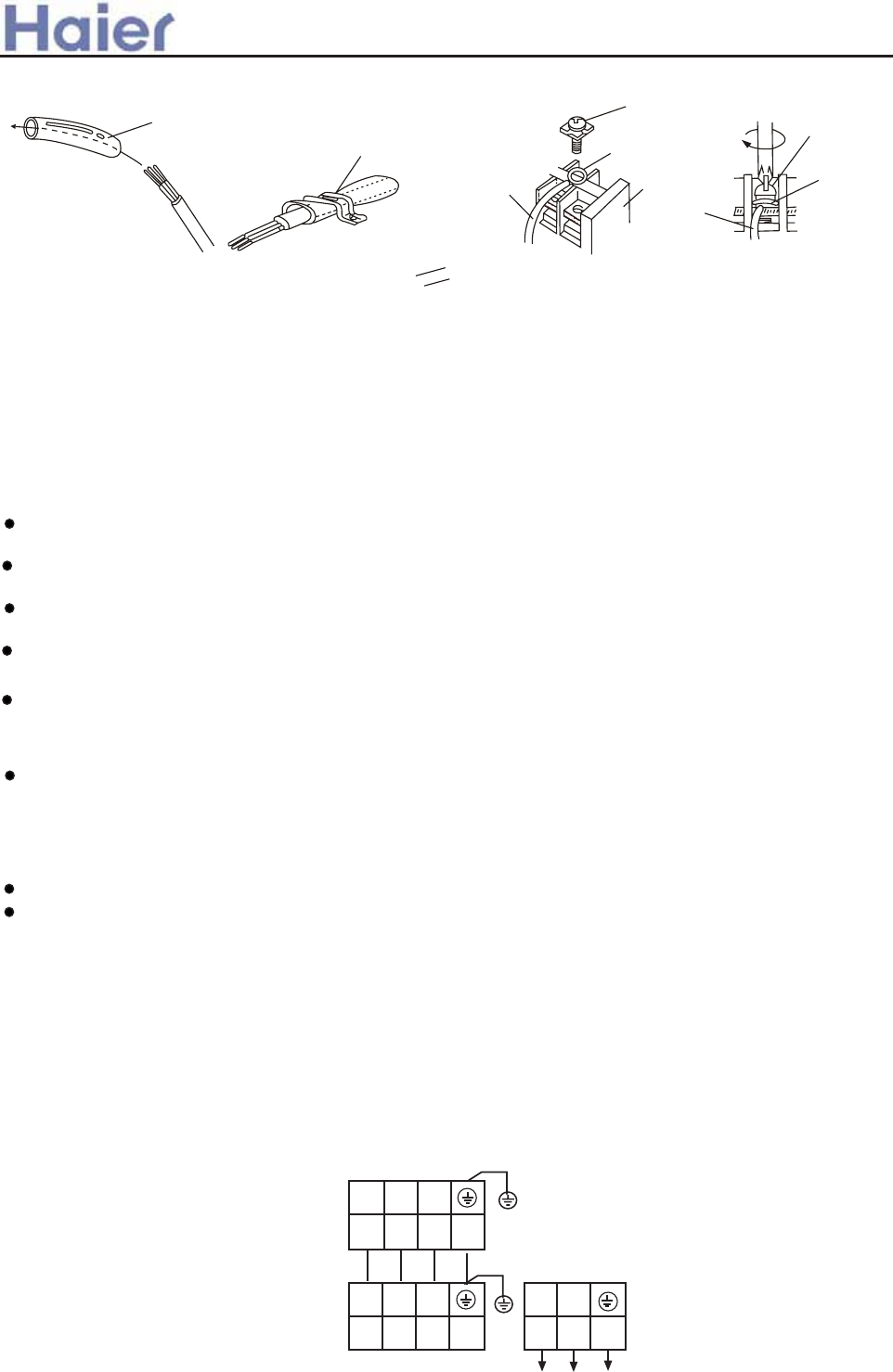
Screw with
special washer
Screw with
special washer
Round
terminal
Round
terminal
Terminal
board
Wire
Wire
Fig. 18
Use VW-1, 0.5 to 1.0 mm thick, PVC tube as the insulation tube.
Insulation tube
Cord clamp
>a__WcU[S^<[c>a`V[e[a`Wc
Check the Layout of the Drain Pipe and Connection Wires
The drain pipe should be placed underneath, and the connection wires should be placed upside; and
the drain pipe especially the section inside the machine and indoors must be wound up with insulating
material to preserve heat. The drain pipe shall be sloped and no concave and convex shall occur along
the whole pipe. And the cases as the right figure indicates shall not occur.
Installation check
Is power supply voltage required?
Is water completely drained to outdoors?
Are power wire and connection wires between indoor and outdoor units correctly connected?
Is any gas leaked from the pipe connectors?
Are series numbers of the terminals on the indoor and outdoor units corresponding to each
other? Is the connection section of the auxiliary pipe insulated? Is the indoor unit fixed firmly?
Is noise big?
The person who has completed this installation shall be requested to conduct a test operation for check:
Is the temperature adjuster working normally?
Does the location for installation conform to requirements?
Winding up with Protective Plastic Tape
The connection pipes, drain pipe, and the connection wires shall be wound up with PVC tape.
Notes: The connection pipes shall also be wound up with insulating material to preserve the
temperature. The airing direction shall be from bottom to top.
Trial Operation
INSTALLATION CHECK AND TRIAL OPERATION
KQWQTP NQLPWLS MOY[OOT HGJGFIGJG
ADC>AAB
?@>AAB
-,+
+,-
YU VU[OW XZVVR\
AU182AFERA/AS182AVERA
75
-117-
Y/G
Y/G
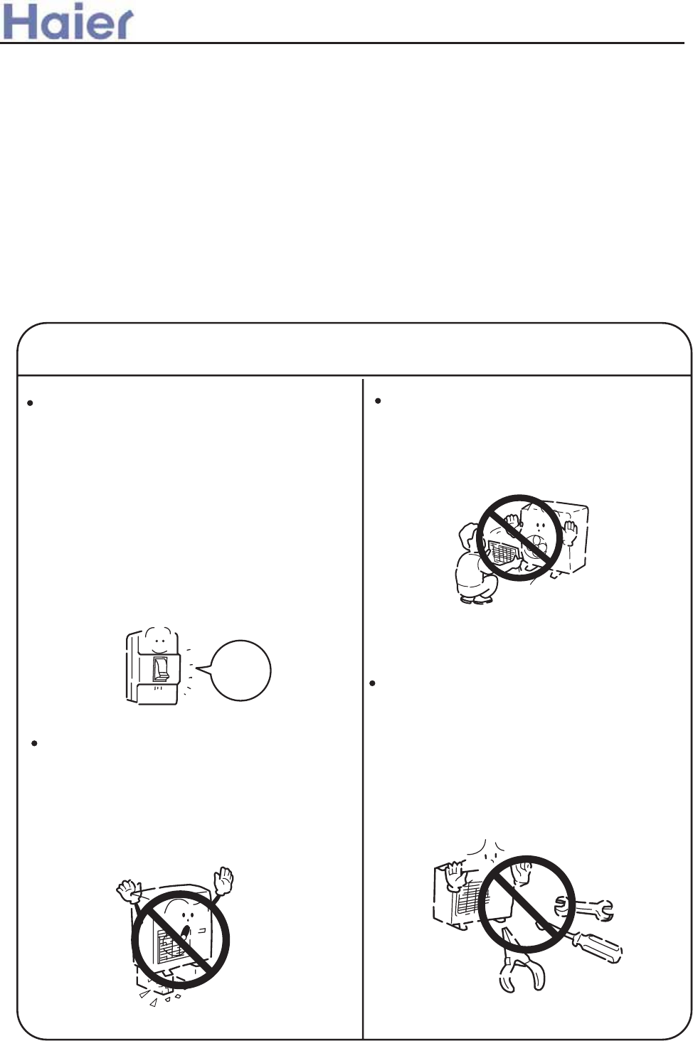
Carefully read the following information in order to operate the airconditioner correctly.
Below are listed three kinds of Safety Cautions and Suggestions.
WARNING!
CAUTION! Incorrect operations may result in injuries or machine damages; in some cases may
cause serious consequences.
Incorrect operations may result in severe consequences of death or serious injuries.
INSTRUCTIONS: These information can ensure the correct operation of the machine.
Be sure to conform with the following important Safety Cautions.
The Safety Cautions should be at hand so that they can be checked at any time when needed.
If the conditioner is transferred to the new user, this manual should be as well transferred to the new user.
WARNING!
If any abnormal phenomena is found
(e. g.smell of firing), please cut off the
power supply immediately, and contact
the dealer to find out the handling
method.
Don't dismantle the outlet of the
outdoor unit.
The exposed fan is very dangerous
which may harm human beings.
switch
off
In such case, to continue using the
conditioner will damage the conditioner,
and may cause electrical shock or fire
hazard.
Incorrect maintenance and repairment
may cause water leak, electrical shock
and fire hazard.
When the unit needs maintenance and
repairment, please call dealer to handle it.
After the unit being used for a long time,
the base should be checked for any
damages.
If the damaged base is not repaired, the
unit may fall down and cause accidents.
>a__WcU[S^<[c>a`V[e[a`Wc
6.9 Outdoor unit (AU18-AU60)
-118-
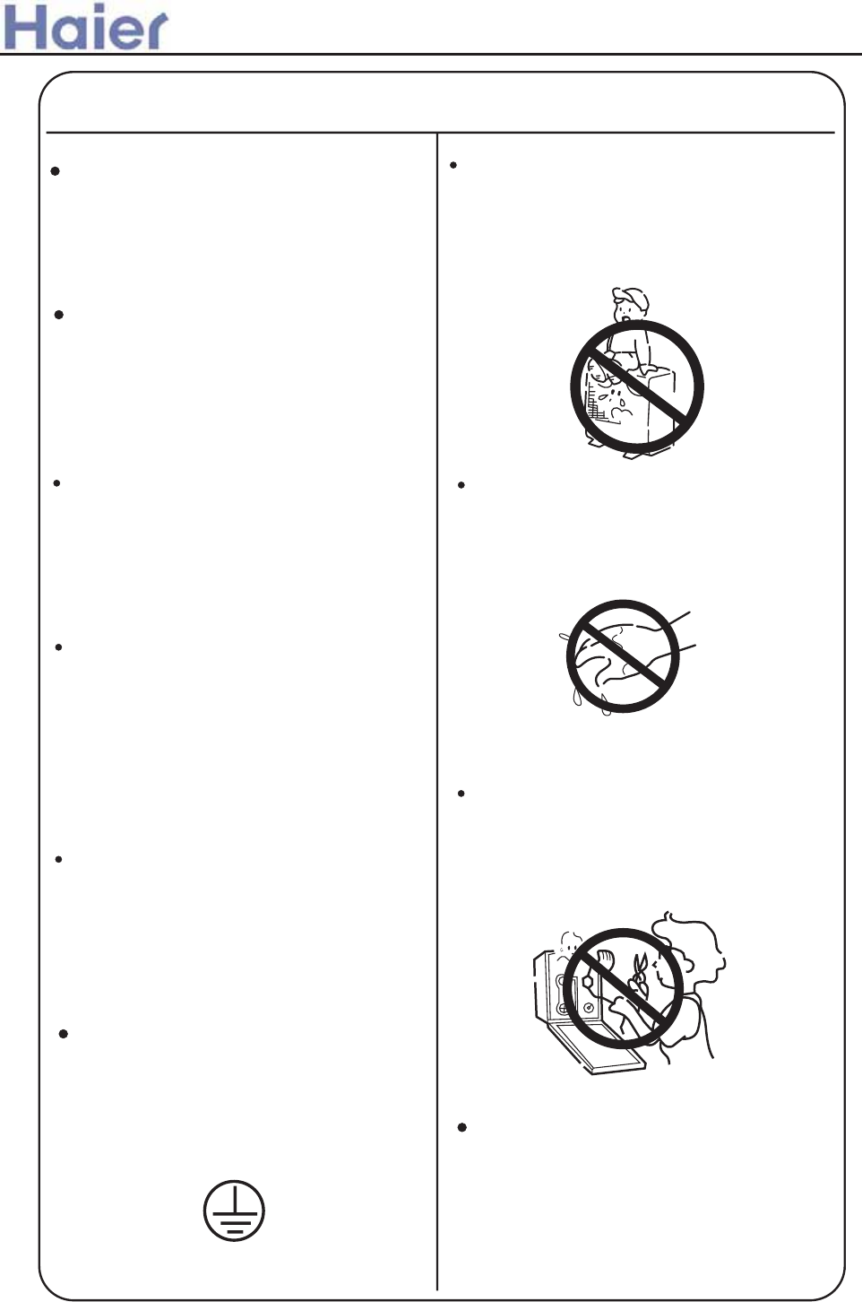
>a__WcU[S^<[c>a`V[e[a`Wc
Air-conditioner can't be installed in
the environment with inflammable
gases because the inflammable gases
near to air-conditioner may cause fire
hazard.
Connect earthing wire.
Use discharge pipe correctly to ensure
efficient discharge.
Earthing wire should not be con-
nected to the gas pipe, water pipe,
lightning rod or phone line, in-correct
earthing may cause shock.
Incorrect pipe use may cause water
leaking.
Earthing
WARNING!
Installed electrical-leaking circuit
breaker.
It easily cause electrical shock without
circuit breaker.
Please let the dealer be responsible for
installing the conditioner.
Incorrect installation may cause water
leak, electrical shock and fire hazard.
Call the dealer to take measures to
prevent the refrigerant from leaking.
If conditioner is installed in a small
room be sure to take every measure in
order to prevent suffocation accident
even in case of refrigerant leakage.
When conditioner is deinstalled or
reinstalleddealer should be responsible
for them.
Incorrect installation may cause water
leaking, electrical shock and fire hazard.
No goods or nobody is permitted to
placed on or stand on outdoor unit.
The falling of goods and people may
cause accidents.
Don't operate the air-conditioner with
damp hands.
Otherwise will be shocked.
Only use correctly-typed fuse.
May not use wire or any other materials
replacing fuse, other-wise may cause
faults or fire accidents.
-119-
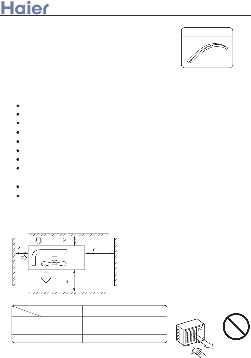
Note :
(1). Fix the parts with screws
(2).Don't intake the strong wind directly to the
outlet air-flow hole.
(3).A one meter distance should be kept from the
unit top
(4).Don't block the surroundings of the unit with
sundries
2. Selection of the place of installation
1. Accessories
"Edging" for protection of electric wires from an
opening edge.
Select the place of installation satisfying the following conditions and, at the
same time, obtain a consent from the client or user.
Edging
Place where air circulates.
Place free from heat radiation from other heat sources.
Place where drain water may be discharged.
Place where noise and hot air may not disturb the neighborhood.
Place where there is not heavy snowfall in the winter time.
Place where obstacles do not exist near the air inlet and air outlet .
Place where the air outlet may not be exposed to a strong wind.
Place surrounded at four sides are not suitable for installation. A 1m or more
of overhead space is needed for the unit.
Mount guide-louvers to place where short-circuit is a possibility.
When installing several units, secure sufficient suction space to avoid short
circuiting.
Wind direction
NO
(2) Installation where the area with strong winds.
Install the unit so that the air outlet section of the unit must NOT be faced
toward wind direction.
(1) Open space requirement around the unit
L2
L3
L1
500
(Servicing
space)
Air outlet
Air inlet
Air
inlet
Case
Distance
Unit: mm
open open
open
500
150
150 300
300 0
L1
L2
L3
III III
>a__WcU[S^<[c>a`V[e[a`Wc
-120-
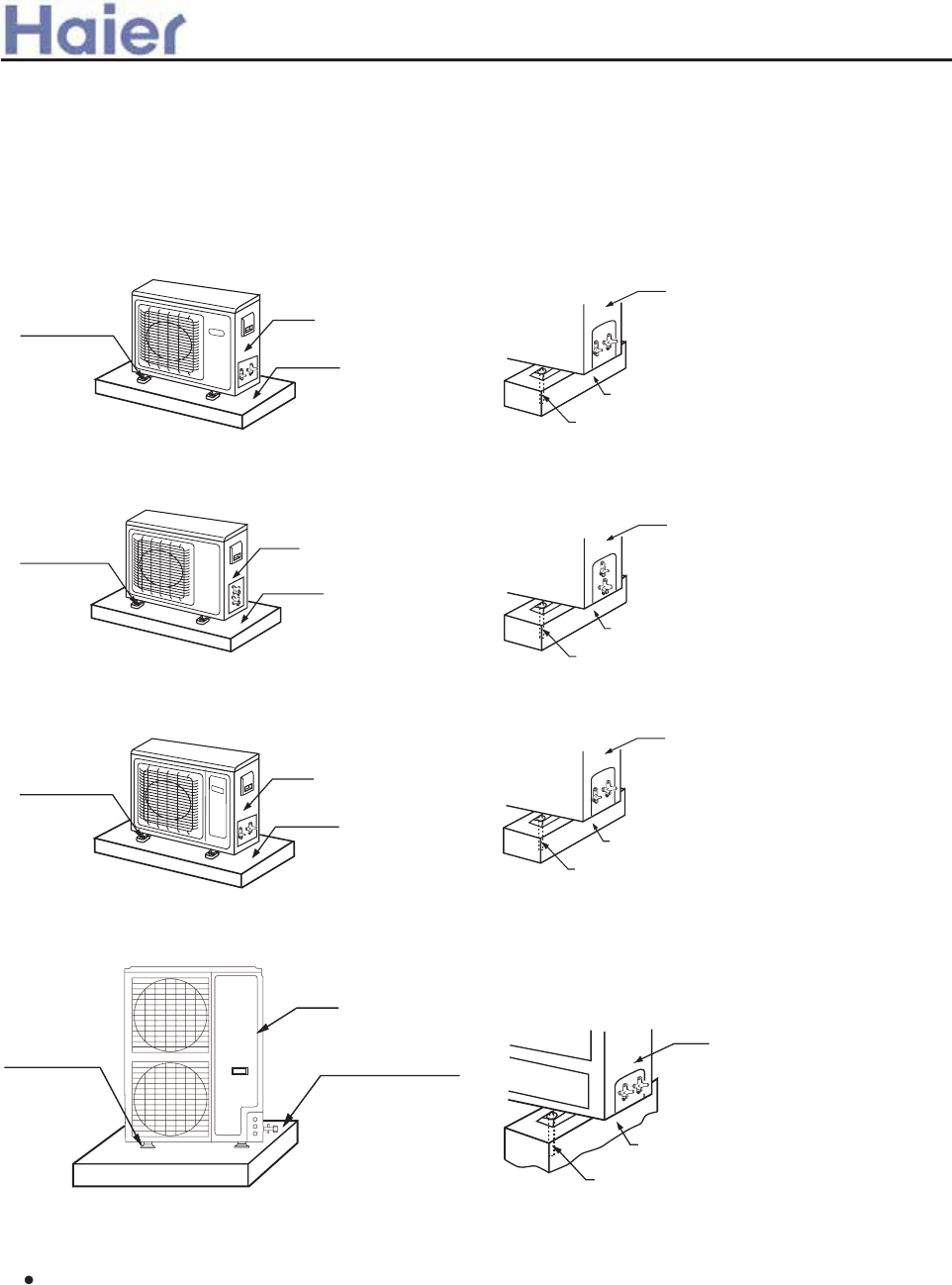
+L,=XWN[P]P QX^WOL]TXW +M, ?X^WOL]TXW LWNSX[
+M, ?X^WOL]TXW LWNSX[
+L, =XWN[P]P QX^WOL]TXW
+L, =XWN[P]P QX^WOL]TXW +M, ?X^WOL]TXW LWNSX[
+L, =XWN[P]P QX^WOL]TXW +M, ?X^WOL]TXW LWNSX[
ig jpstkooktnqp qm qutlqqr upnt
?Ta ]SP ^WT] TW L Y[XYP[ `Lb LNNX[OTWR ]X ]SP NXWOT]TXW XQ L YULNP `SP[P T] T\
TW\]LUUPO Mb [PQP[[TWR ]X ]SP QXUUX`TWR 0
ehf jpstkooktnqp
<J293<>><<. <J293<?>H<
<J393<A><< <J39E<A><< <J473<A>H<
BW\]LUU ]SP ^WT] \X ]SL] ]SP LWRUP XQ TWNUTWL]TXW V^\] MP UP\\ ]SLW 4 OPR[PP\0
EX]P; +2, @T_P PWX^RS [XXV QX[ ]SP NXWN[P]P QX^WOL]TXW ]X QTa Mb LWNSX[ MXU]\0
+3, GULNP ]SP NXWN[P]P QX^WOL]TXW OPPY PWX^RS0
JWT]
=XWN[P]P QX^WOL]TXW
<WNSX[ MXU]
<J353<@><<. <J353<@>H<. <J53E<C><<
=XWN[P]P QX^WOL]TXW
JWT]
<WNSX[ MXU]
<WNSX[ MXU]
=XWN[P]P QX^WOL]TXW
JWT]
IX QTa Mb MXU]\
<J473<B><<. <J47E<B><<. <J59E<B><<. <J71E<B><<
=XWN[P]P QX^WOL]TXW
JWT]
<WNSX[ MXU]
<WNSX[ MXU]
=XWN[P]P QX^WOL]TXW
JWT]
IX QTa Mb MXU]\
=XWN[P]P QX^WOL]TXW
JWT]
<WNSX[ MXU]
<WNSX[ MXU]
=XWN[P]P QX^WOL]TXW
JWT]
IX QTa Mb MXU]\
JWT]
IX QTa Mb MXU]\
<WNSX[ MXU] =XWN[P]P QX^WOL]TXW
>a__WcU[S^<[c>a`V[e[a`Wc
-121-
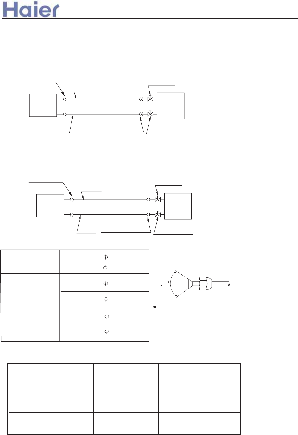
>a__WcU[S^<[c>a`V[e[a`Wc
+3, GTYTWR \TcP
@L\ YTYP 26099a201VV
BW\]LUU ]SP [PVX_PO QUL[P W^]\ ]X
]SP YTYP\ ]X MP NXWWPN]PO. ]SPW
QUL[P ]SP YTYP\0
CTZ^TO YTYP
@L\ YTYP
:063a109VV
2:016a201VV
CTZ^TO YTYP :063a109VV
+4, CTVT]L]TXW\ QX[ XWP `Lb YTYTWR UPWR]S LWO _P[]TNLU SPTRS] OTQQP[PWNP0
@L\ YTYP 2308a201VV
CTZ^TO YTYP 7046a109VV
<J293<>><< UP\\ ]SLW 31 V
+2, F^]UTWP YTYTWR
50 HPQ[TRP[LW] YTYTWR
F^]OXX[
^WT]
4/`Lb \]XY _LU_P
@L\ YTYP
CTZ^TO
YTYP
?UL[P NXWWPN]TXW
BWOXX[
^WT]
?UL[P NXWWPN]TXW 4/`Lb \]XY _LU_P
F^]OXX[
^WT]
4/`Lb \]XY _LU_P
@L\ YTYP
CTZ^TO
YTYP
?UL[P NXWWPN]TXW
BWOXX[
^WT]
?UL[P NXWWPN]TXW 3/`Lb \]XY _LU_P
<J293<>><<. <J293<?>H<
<J353<@><<. <J393<A><<. <J39E<A><<. <J473<B><<. <J47E<B><<. <J53E<C><<.
<J59E<B><<. <J71E<B><<. <J353<@>H<. <J473<A>H<
<J473<B><<
<J47E<B><<
<J53E<C><<
<J59E<B><<
<J71E<B><<
:1-106
<J353<@><<
<J393<A><<
<J39E<A><<
<J353<@>H<
<J473<A>H<
<J293<>><<
<J293<?>H<
DXOPU FWP `Lb YTYTWR UPWR]S KP[]TNLU SPTRS] OTQQP[PWNP
+MP]`PPW TWOXX[ LWO X^]OXX[,
UP\\ ]SLW 41 V
<J473<B><< <J47E<B><<
<J53E<C><< <J59E<B><<
<J71E<B><< <J473<A>H<
<J353<@><< <J393<A><<
<J39E<A><<
<J293<?>H< <J353<@>H<
UP\\ ]SLW 61 V
UP\\ ]SLW 26 V
UP\\ ]SLW 41 V
UP\\ ]SLW 21 V
-122-
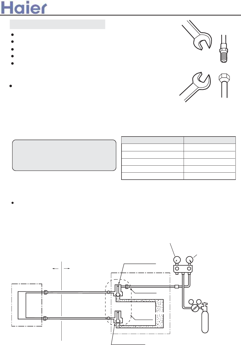
97.2-118.6N.m
Precautions for refrigerant piping
Do not twist or crush piping.
Be sure that no dust is mixed in piping.
Bend piping with as wide angle as possible.
Keep insulating both gas and liquid piping.
Check flare-connected area for gas leakage.
Connecting method (indoor unit)
Apply refrigerant oil at half union as large and flare nut.
To bend a pipe, give the roundness as possible not to crush
the pipe.
When connecting pipe, hold the pipe centre to centre then
screw nut on by hand, refer to Fig.
Be careful not to let foreign matters, such as sands enter
the pipe.
Piping connection
Forced fastening without centering
may damage the threads and cause
a gas leakage.
Pipe dia Fastening torque
Liquid pipe 6.35mm
Gas pipe 15.88mm
Liquid pipe 9.52mm
Gas pipe 19.05mm
14.2-17.2N.m
61.8-75.4N.m
32.7-39.9N.m
Gas pipe 12.7mm 49.5-60.3N.m
After finishing connection of refrigerant pipe, it shall perform air tightness test.
The air tightness test adopts nitrogen tank to give pressure according to the pipe connection mode as
the following figure shown.
The gas and liquid valve are all in close state. In order to prevent the nitrogen entering the circulation
system of outdoor unit, tighten the valve rod before giving pressure (both gas and liquid valve rods).
Outdoor
Completely tightened
Completely tightened
Flare part
Outdoor units
Mainhole
Discharging valve
3-way valve totally closed
(Gas side)
Low pressure gauge
High pressure gauge
Meter separator
Dropping valve
2-way valve totally closed
(Liquid side)
Nitrogen tank
VLVH
Indoor units
Indoor
Flare part
First step: 0.3MPa (3.0kg/cm2g) pressurize over 3 minutes.
Second step: 1.5Mpa (15kg/cm2g) pressurize over 3 minutes. Large leakage will be found.
Third step: 3.0 MPa (30kg/cm2g) pressurize about 24 hours. Little leakage will be found.
Air discharging method
>a__WcU[S^<[c>a`V[e[a`Wc
-123-
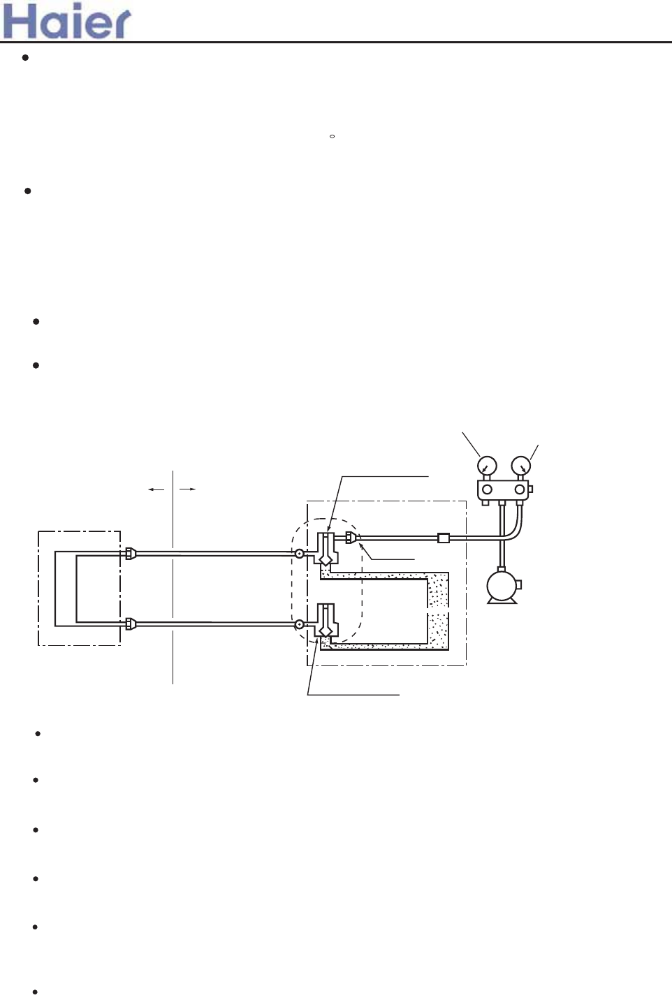
It shall use the vacuum pump of (lower than -755mmHg)high vacuum degree and large air
discharging (over 40l/min).
The vacuumizing time depends on the length of the connecting pipe, generally is 1~2 hours.
When vacuumizing, it shall be confirmed both gas and liquid side valves are closed.
If after 2 hours vacuumizing, it cannot reach the vacuum degree below -755mmHg, it can be
vacuumized for other 1 hour.
If after 3 hours vacuumizing, it still cannot reach the vacuum degree below -755mmHg, check
if there is any leaking point and repair the them.
If after over 2 hours vacuumizing, the vacuum degree is below -755mmHg, close the VL and VH
on the meter separator and stop vacuumizing. 1 hour later to confirm if the vacuum degree changes.
If changes,it indicates there is leaking point in the system. Check the leaking point and repair.
After finishing the above vacuumizing, change the vacuum pump into refrigerant pump to charge
the refrigerant.
2-way valve totally closed
(Liquid side)
Indoor units
Indoor Outdoor
Completely tightened
Completely tightened
Outdoor units
Vacuum pump
Discharging valve
3-way valve totally closed
(Gas side)
Low pressure gauge High pressure gauge
Meter separator
V L VH
Flare part
Flare part
P
From the first to third steps, if the pressure drops, check the leakage in each joint by the sense of
hearing, feeling or soap water, etc. to find the leaking point.
After confirming the leaking point, welding it again or tighten the nut tightly again.
Checking the leaking point
After pressurizing for 24 hours, each 1 C difference of ambient temperature
will result in 0.01MPa(0.1kg/cm2g) pressure change. It shall be corrected during test.
Check if the pressure drops
If the pressure does not drop, the unit is passed
If the pressure drops, please check the leaking point.
Use vacuum pump to perform vacuumizing. It is strictly forbidden to use the refrigerant to remove
the air inside the system.
After air tightness test and discharging all the nitrogen, connect the vacuum pump as the following
figure shown.
Piping and indoor unit vacuumizing
>a__WcU[S^<[c>a`V[e[a`Wc
-124-
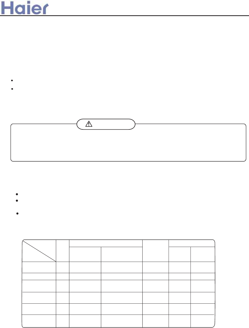
Electric wiring
DANGER OF BODILY INJURY OR DEATH
TURN OFF ELECTRIC POWER AT CIRCUIT BREAKER OR POWER SOURCE BEFORE MAKING ANY
ELECTRIC CONNECTIONS.GROUND CONNECTIONS MUST BE COMPLETED BEFORE MAKING
LINE VOLTAGE CONNECTIONS.
WARNING
When the total length (L) of the two indoor units' connecting pipe is less than 5m, it is unnecessary
to charge additional refrigerant.
If the connecting pipe (L) exceeds 5m, it shall charge Mg additional refrigerant per meter.
That is: Refrigerant charging amount = (L-5) x M (g)
For the unit with liquid pipe 6.35mm, M=30
For the unit with liquid pipe 9.52mm, M=
Only in COOLING operation can charge the additional refrigerant.
When charging, the refrigerant shall be charged from the charging nozzle of low pressure vavle.
Be carefull when charging refrigerant, do not let the air mix into the system,and must charge
the additional refrigerant in liquid condition.
Charging amount of refrigerant
(1) Selection of size of power supply and interconnecting
Precautions for Electric wiring
Electric wiring work should be conducted only by authorized personnel.
Do not connect more than three wires to the terminal block. Always use round type crimped
terminal lugs with insulated grip on the ends of the wires.
Use copper conductor only.
Select wire sizes and circuit protection from table below. (This table shows 20 m
length wires with less than 2% voltage drop.)
>a__WcU[S^<[c>a`V[e[a`Wc
50 -
41
DdW^
H`VW] KZScW
4
Mg[dUZ TbWS\Wb
+<,
>[bUe[d TbWS\Wb
JfWbUebbW_d
ab`dWUd`b
K`gWb
c`ebUW g[bW
c[jW +^^
3
,
41 31 5/1
2 51 37 3/6
Mg[dUZ
TbWS\Wb
@SbdZ ]WS\SYW TbWS\Wb
GWS\
UebbW_d+^<,
41
51
<O58I<D@<<
<O71I<D@<<
<O283<@@<<
<O283<A@L<
441 3/6 4131
2 51 37 7/1 51 41
41
41
<O353<B@<<
2 51 37 5/1 51 41
<O353<B@L<
<O473<C@L<
2 71 51 5/1 71 41
AU362AIEAA
AU282AHEAA
AU36NAIEAA
AU28NAHEAA
(2) Wiring connection
Make wiring to supply power to the outdoor unit, so that the power for the indoor unit is supplied by
terminals.
For the detailed wiring connection with the indoor units, see the corresponding indoor
operation and instruction manual.
-125-
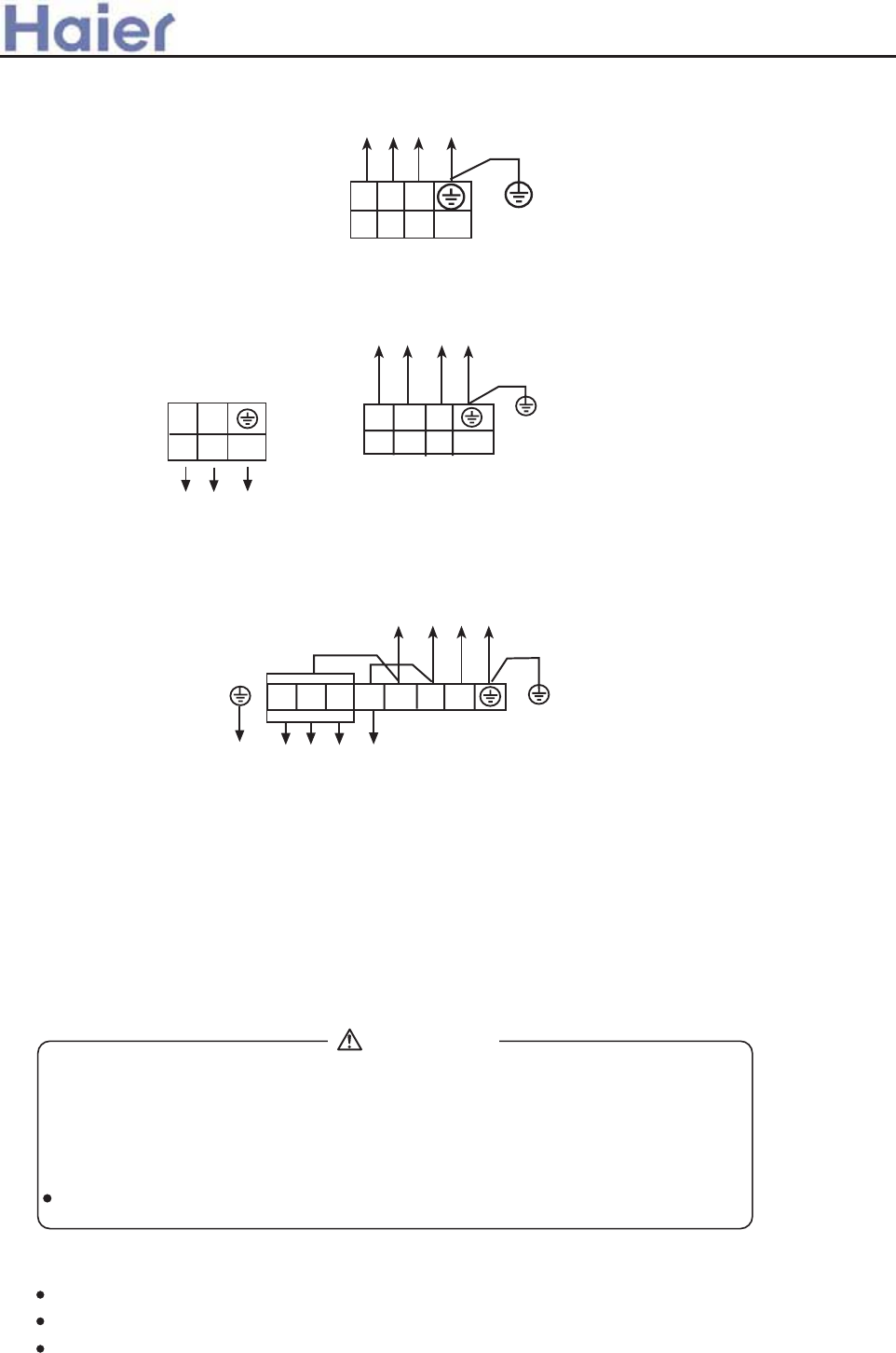
>a__WcU[S^<[c>a`V[e[a`Wc
For: AU182AEEAA
OUTDOOR UNIT
TERMINAL BLOCK
1 2 3
To Indoor Unit
Y/G
1PH, 220-230V~, 50Hz
POWERSUPPLY:
OUTDOOR UNIT
TERMINAL BLOCK
L N
1 2 3
Y/G
To Indoor Unit
OUTDOOR UNIT
TERMINAL BLOCK
POWER SUPPLY:
380-400V, 3N~, 50Hz
N 1 2 3
Y/G
To Indoor Unit
R S T
For: AU242AGEAA, AU282AHEAA, AU182AFERA, AU242AGERA
For: AU28NAHEAA, AU36NAIEAA, AU48NAIEAA, AU60NAIEAA
Test run
Run the unit continuously for about 30 minutes, and check the following.
Suction pressure at check joint of service valve for gas pipe.
Discharge pressure at check joint on the compressor discharge pipe.
Temperature difference between return air and supply air for indoor unit.
CAUTION
THIS UNIT WILL BE STARTED INSTANTLY WITHOUT "ON" OPERATION
WHEN ELECTRIC POWER IS SUPPLIED.BE SURE TO EXECUTE "OFF"
OPERATION BEFORE ELECTRIC POWER IS DISCONNECTED FOR
SERVICING.
This unit has a function of automatic restart system after recovering power stoppage.
(3) Wiring procedure
1) Remove the screws on the side before taking off the front panel toward the direction shown in figure.
2) Connect wires to the terminal block correctly and fix the wires with a wire clamp equipped nearby the
terminal block.
3) Route the wires in a proper way and penetrate the wires through the opening for electric wiring on the
side plate.
-126-
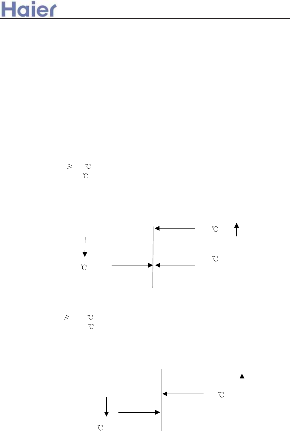
7.1.1 Control Features
The brief introduction includes those for each item of various types of air conditioners and
their electric control functions.
The brief introduction includes those for each item of various types of air conditioners and
their electric control functions.
1) Brief introduction of electric control
(1) Automatic run (1) Automatic run
a. Cooling-heating type
After the machine being started and running mode changes to AUTO, the system will
decide running mode according to difference between the present room temperature and
setting temperature, then runs as the decided mode. In the following selections, Tr means
room temperature and Ts means setting temperature.
Select running mode according to the following conditions at the first time to enter Auto
mode:
TrTs-3 to select cooling mode (with setting temperature being Ts +3)
Tr<Ts-3 to select heating mode (with setting temperature being Ts)
After the system entering auto run mode, the running mode can convert automatically
according to variation of room temperature between cooling, blowing and heating in the way
shown as the chart below:
Cooling
Ts+3
Cooling
Room
temperature
rising
Blowing
Ts-3
Ts-3
Heating
b. Single Cooling Type
Select running mode according to the following conditions at the first time to enter Auto
mode:
Tr
Ts + 3 to select cooling mode
Tr < Ts + 3 to select blowing mode
After the system entering auto run, the running mode can convert automatically
according to variation of room temperature between cooling and blowing functions in the way
shown as the chart below:
Ts+3
Blowing
Blowing
Ts-3
7Electric control functions
>a__WcU[S^<[c>a`V[e[a`Wc
7.1 Fixed frequency unit
Room
temperature
falling
Room
temperature
rising
Room
temperature
falling
Cooling
Cooling
-127-
Heating
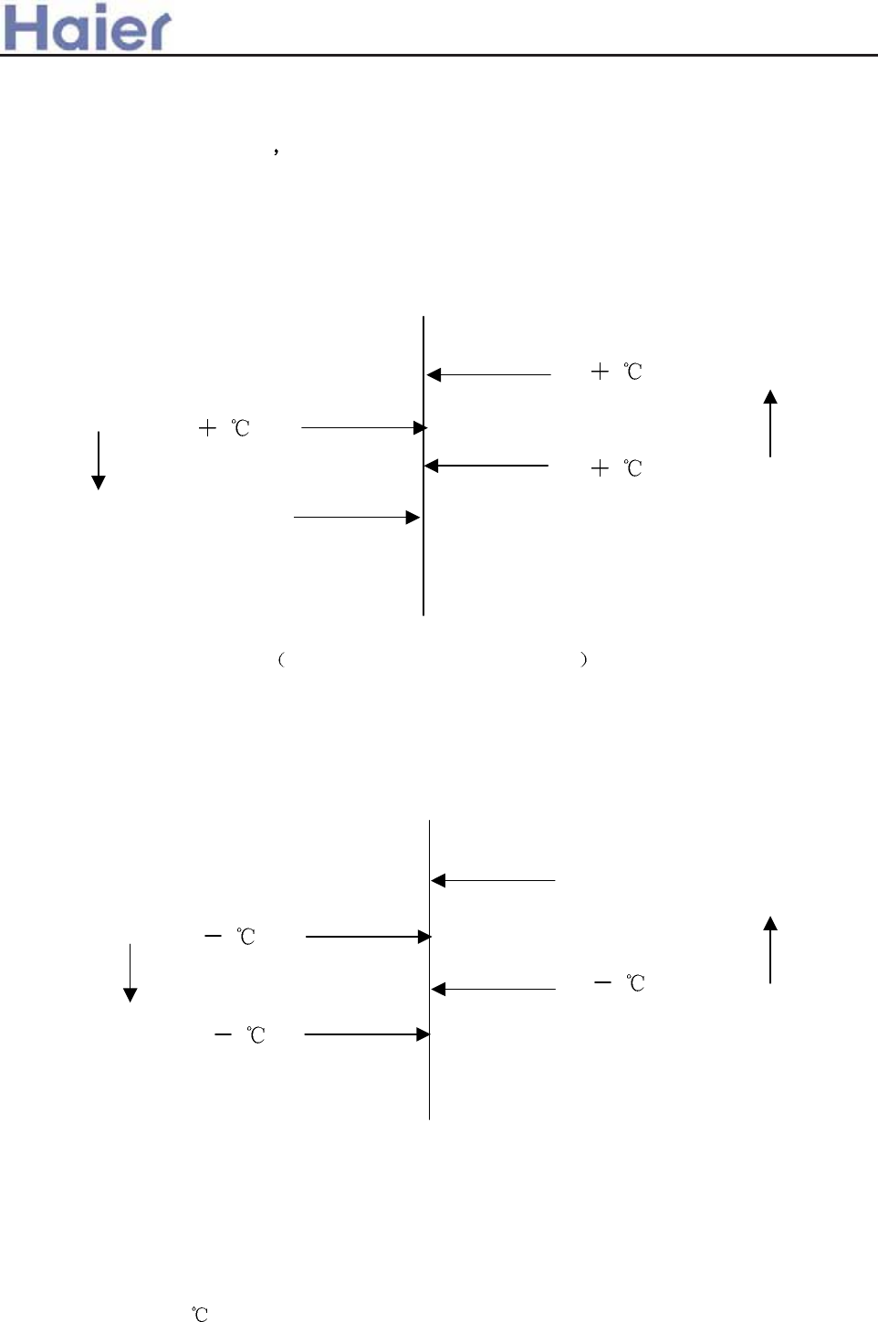
(2) Auto Selection of Wind Speed
In the following, Tr means room temperature while Ts means setting temperature.
a. During cooling program conversion of wind speed from the low to high won’t work until
the present speed has continued for 3 minutes while conversion from the high to low needs
no time delay. The chart below is the sketch map of conversion:
Ts 2
Ts 1
Medium speed
Low speed
High speed
Ts 3
Ts
b. During heating program applicable for cooling-heating type , conversion of wind speed
from the low to high won’t work until the present speed has continued for 3 minutes while
conversion from the high to low needs no time delay. The hart below is the sketch map of
conversion:
Ts 1
Ts 2
Ts
Ts 3
(3) Dehumidifying program
In the following, Tr means room temperature while Ts means setting temperature.
a. After the system entering dehumidifying program, the compressor, outdoor and indoor
blowing fans run according to the following rules:
(1) Tr > Ts + 2 , the compressor and outdoor blowing fan run continuously while indoor
>a__WcU[S^<[c>a`V[e[a`Wc
Low speed
Medium speed
High speed
High speed
High speed
Medium speed
Medium speed
Low speed
Low speed
temperature
falling
temperature
falling
temperature
rising
temperature
rising
-128-
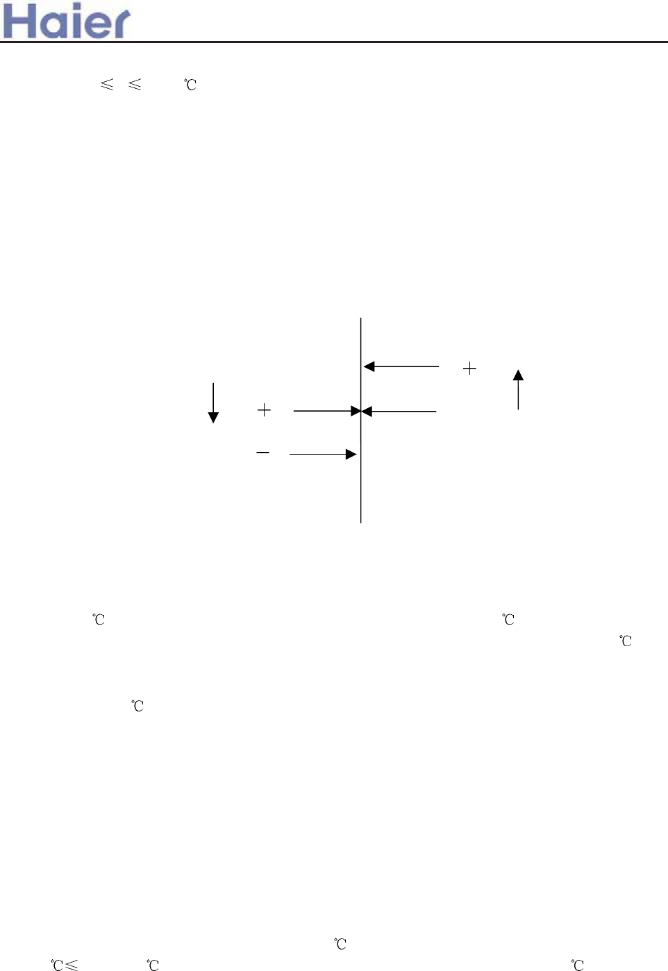
blowing fan runs at setting wind speed. This working area is defined as area A.
(2) Ts Tr Ts + 2 , the compressor and outdoor blowing fan run for 10 minutes then
pause for 6 minutes, while indoor blowing fan runs at low wind speed. This working
area is defined as area B.
(3) Tr < Ts, the compressor and outdoor blowing fan stop working while indoor blowing
fan runs at low wind speed. This working area is defined as area C.
a. After dehumidifying program starting, the system converts between A, B and C areas
according to variations of room temperature with running mode being shown as the chart
below:
Area B
Area B Area C
Ts+1
Area A
Area A
Ts 3
Ts 1
Ts 1
Area C
(4) Cutoff protection against overload and overheat
During heating program, if the indoor blowing fan has been started and the compressor
has been running more than 2 minutes, and the temperature of indoor coil pipe (Ticp)
> 64 , the outdoor blowing fan will stops running; If Ticp 50 and the outdoor
blowing fan has kept stop state for 45 seconds, then it will restore rotation; If Ticp > 67
and such temperature has last for 10 seconds, the compressor will stop running and
indoor blowing fan run according to conditions as it reaches setting temperature. When
Ticp < 58 , and the compressor has kept stop state over 3 minutes, then the
compressor and outdoor blowing fan will restore normal running.
Cutoff protection for heating current
After 60 seconds from the compressor being started, if CT current exceeds I1 (9.2A) and
such case has kept 5 seconds, the outdoor blowing fan will stop. If 45 seconds has passed
after the outdoor blowing stops and the current of the compressor is less than I2 (7.5A), the
blowing fan will restore running. If CT current exceeds I3 (14.3A) and such case lasts for 3
seconds, the compressor and outdoor blowing fan will stop. The compressor will not restore
running until 3 minutes passes with CT current less than 12A.
(5) Cool wind prevention during heating program
At the first time entering heating program or after ending the latest frost removal, if the
temperature of indoor coil pipe (Ticp) < 28 , the indoor blowing fan will stop running; If
28 Ticp < 38 , the indoor blowing fan will run at low speed; If Ticp > 38 or the
compressor has been running for more than 4 minutes, the indoor blowing fan will run at
>a__WcU[S^<[c>a`V[e[a`Wc
Room
temperature
rising
Room
temperature
falling
-129-
setting wind speed.
(6) Afterheat blowing during heating program
During heating program, the compressor will stop running (except overheat protection or
frost removal) while the indoor blowing fan will firstly run for 50 seconds at low speed then
stop.
(7) Frost removal control (applicable for cooling-heating type)
Starting conditions for frost removal:
A The indoor unit is in overload protection and outdoor blowing fan stops. The outdoor
blowing fan does not enter overheat mode in 10 minutes after it is restarted, the
compressor has run over 45 minutes totally while 20 minutes continuously, and the
temperature of indoor coil pipe is lower than 43 ;
B After the compressor continuously running for 20 minutes, the temperature of indoor
coil pipe falls 1 every 6 minutes and such case continuously appears three times,
and the temperature of indoor coil pipe is less than 40 , and 5 minutes have passed
after the compressor is restarted;
C The compressor has run totally over 3 hours while 20 minutes continuously, and the
temperature of indoor coil pipe is less than 40 ;
D The difference between room temperature and the one of indoor coil pipe is less than
16 and the compressor has totally run over 45 minutes while 20 minutes
continuously;
Frost removal will start if any one of the above conditions is satisfied.
Ending conditions for frost removal:
1 Time of frost removal has exceeded 9 minutes;
2 CT current exceeds I4(8.2A)
Actions of each load after the frost removal starts:
The compressor and outdoor blowing fan stop, and indoor blowing fan also stops.
55 seconds later the reversal valve is closed and next 5 seconds later the compressor is
started.
Actions of each load after the frost removal ends:
The compressor stops running while outdoor blowing fan immediately runs at high
speed, 55 seconds later the reversal valve is opened and next 5 seconds later the
compressor restores running and indoor blowing fan runs as conditions for cool wind
prevention.
(8) Freeze protection
After the compressor has run for 9 minutes, the system will check temperature of
indoor coil pipe (Ticp). If Ticp is less than -1 , the compressor and outdoor blowing
fan will stop. They will run again after the compressor stops if both the following
conditions are satisfied:
1) 3 minutes have passed since compressor stops.
2) Ticp exceeds 7 .
(9) 3 minutes protection for compressor
After compressor stops, it cannot be started until 3 minutes later. During the machine’s
running, if time after loosing power not exceeds 3 minutes, the compressor cannot be
>a__WcU[S^<[c>a`V[e[a`Wc
-130-
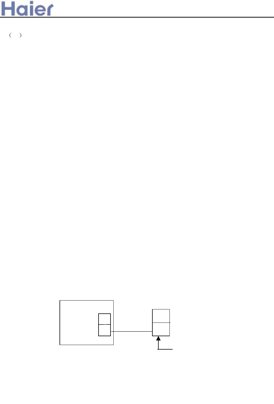
restarted until 3 minutes later after it is reenergized.
10 Power breakdown memory
If the machine suddenly loses power while running, or stops for maintenance or trouble
shooting, it will restart running as the status when it stops after the power is restored.
Note: 1. Function setting: Continuously press sleep button on the remote controller 10
times in 5 seconds and buzzer on control panel shall beep 4 times.
2. Memory content: Running mode, wind speed setting, temperature setting,
swing status.
3. Cancel: Press sleep button on the remote controller 10 times and buzzer on
control panel beeps 2 times.
(11) Control of water pump
a. In cooling (including automatic cooling mode) and dehumidifying modes, the water
pump works if the compressor runs while stops 5 minutes later after the compressor
stops.
b. When water tank is fully filled, the float switch will be off. The water pump will start
to work after a controller has detected this signal and it will continue working for 5
minutes after the float restores to normal state.
c. If the full water signal is detected continuously over 5 minutes, the water pump
indicator lamp will flash to alarm and compressor stops running. The water pump
will run 5 minutes, then pause for 5 seconds before next 5 minutes’ running, ... until
the float restores to normal state, after which the pump will run for 5 minutes then
stop.
(12) Monitoring of remote network
Through preset interface, the air conditioner is connected to remote control detector
(made by Haier) with 2-core cables for wire communication, to execute instructions sent
from computer or centralized controller via remote control detector and meanwhile send
present running status and trouble information of the machine to remote control detector.
Connection between air conditioner and remote control detector:
CN11
PC board 1
2
A-
A+
Interface for remote
control detector
(13) Trial run
Under shut-down state, hold pressing mandatory button. The buzzer will beep once,
then twice after 5 seconds. Release the button to enter mandatory cooling mode, under
which the indoor blowing fan runs at high speed with both the compressor and outdoor
blowing fan working. Press the mandatory button again can end the mandatory mode.
>a__WcU[S^<[c>a`V[e[a`Wc
-131-
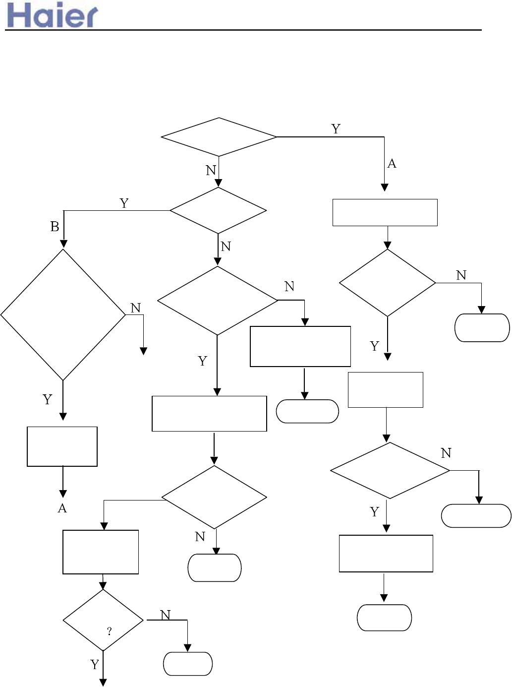
Return
Return
7.1.2 Defrost operation flow chart
Return
Condition
for
compressor
OFF
OFF
compressor
Open outdoor fun
Compressor
off or 55s?
4-way value
ON
Compressor
ON ?
Clear the sign of
defrosts
Return
Operation indoor
fun motor
Return
Come to defrost
Compressor
ON
E-Heat off for 30s?
Turn off compressor
outdoor fun
Turn off
4-way value
Compressor
ON
Return
Return
Turn off for
55s?
B
>a__WcU[S^<[c>a`V[e[a`Wc
-132-
>a__WcU[S^<[c>a`V[e[a`Wc
7.2 Inverter unit
7.2.1 Outdoor running frequency and the control procedure
7.2.1.1 Compressor startup
Compressor running frquency range:
Outdoor temp. ~0ć 0ć~
Heat 20RPS 92RPS 20RPS 83RPS
Cool 20RPS 85RPM 20RPS 85RPS
Defrost 85rpm
Every time compressor is from OFF to ON, no matter how is the indoor target frequency,
compressor running frequency must be stay at 40Hz and 60Hz for 1 minutes (At outdoor discharging
temp. overhigh protection and compressor overcurrent protection, the frequency will be reduced),
and then rise up to the target frequency. After the unit is in normal, the above procedure is not
available.
Note: If the startup frequency for the first time is over 40Hz or 60Hz, it will stay at 40Hz and
60Hz for 1 minute. If the frequency is not over 60Hz, it will only stay at 40Hz for 1 minute. The other
conditions will not be limited.
7.2.1.2 Heating mode, cooling mode and dehumidification
After performing the compressor startup procedure, the unit will run according to the indoor
frequency.
2 minutes later, the unit will compensate the running frequency due to the relative condition.
7.2.1.3 Compressor frequency rising/reducing speed
Rapid rising/reducing frequency speed 1----1Hz/second
Slow rising/reducing frequency speed 1----1Hz/10 seconds
7.2.2 Outdoor motor control
Note: When the outdoor motor needs to change the class, there will be 20-second interval to
avoid the fan speed changing frequently.
7.2.2.1 Fan motor speed class has 7 steps, the rotation and class is as follow:
Class-0 Class-1 Class-2 Class-3 Class-4 Class-5 Class-6 Class-7
stop 160 260 360 460 560 760 860
7.2.2.2 Blowing remain heat after compressor shuts off
In cooling mode, when compressor shuts off, outdoor motor will enter speed Class-5
automatically, and will shut off after blowing remaining heat for 30 seconds.
7.2.2.3 Outdoor motor control in cooling/dry mode
z Speed range: class 1-7
z Fan motor locked rotor: When fan motor is requested to work, if fan speed is measured to be
below 50RPM and keep for 15 seconds, the compressor will stop, but 3 minutes later, it will
re-start up again. If within 20 minutes, the condition occurs 3 times, the unit will stop and alarm.
z When compressor starts up, the unit will adjust automatically in 3 minutes according to the
outdoor air inlet temperature, and 3 minutes later, the unit will adjust according to the outdoor
ambient temperature and compressor running frequency.
Fan speed chart in 3 minutes after compressor starts up:
Ambient temp. ~10 10~25 25~
Cool, dry Class-3 Class-5 Class-7
heat Class-7 Class-5 Class-3
Fan speed chart in 3 minutes after compressor starts up due to the ambient temp. and running
-133-
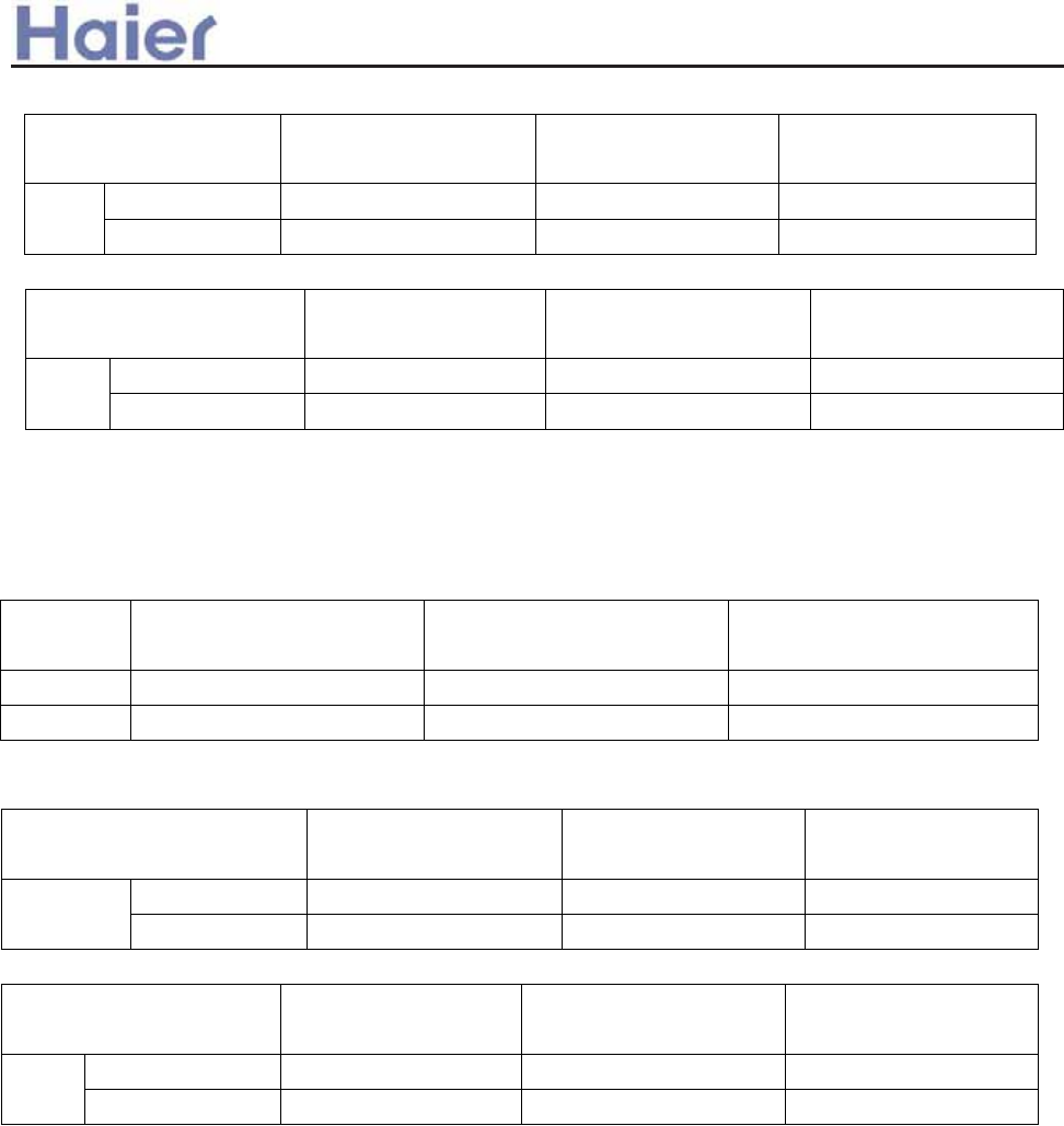
>a__WcU[S^<[c>a`V[e[a`Wc
frequency:
Compressor
frequency in cooling
F<25Hz 25HzİF<45Hz 45İF
Over 28ć Class-3 Class-5 Class-7
Tao
Below 28ć Class-1 Class-3 Class-5
Compressor frequency
in heating
F<25Hz 25HzİF<45Hz 45İF
Over 15ćClass-2 Class-4 Class-5
Tao
Below 15ćClass-3 Class-5 Class-7
7.2.2.4 Outdoor fan speed control when selecting AC motor
z Selecting AC motor or DC motor depends on EEPROM.
z Blowing remaining heat: compressor shuts off, fan motor will run at low speed for 30 seconds
and then stop.
z Fan speed chart in 3 minutes after compressor starts up:
Ambient
temp.
~10 10~25 25~
Cool, dry Low speed High speed High speed
heat High speed High speed Low speed
z Fan speed chart in 3 minutes after compressor starts up due to the ambient temp. and running
frequency:
Compressor frequency in
cooling
F<25Hz 25HzİF<45Hz 45İF
Over 28ćLow speed High speed High speed
Tao
Below 28ćLow speed Low speed High speed
Compressor frequency in
heating
F<25Hz 25HzİF<45Hz 45HzİF
Over 15ćLow speed Low speed High speed
Tao
Below 15ćLow speed High speed High speed
7.2.3 Outdoor electronic expansion valve(EEV) control
7.2.3.1 Movement of EEV
Full-close: after 500 pulse close for 10 times(60 pulse close, 5 pulse open, stop at 5 at last)
Full-open: 480 pulse open
Adjustable upper limitation of open angle: 480 pulse, Adjustable lower limitation of open angle: 5
pulse
Driving speed: open direction: 30.3MS; close direction: 83.3MS
z Drive wave of EEV:
-134-
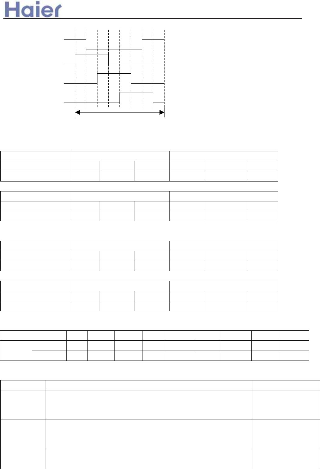
>a__WcU[S^<[c>a`V[e[a`Wc
7.2.3.2 Retentive open angle in 2 minutes after compressor starts up:
z Cool, dry
Outdoor temp. ~22ć 22ć~
Compressor frquency ~30 30~60 60~ ~30 30~60 60~
PMV open angle 230 220 240 260 250 280
z Heat
Outdoor temp. ~6ć 6ć~
Compressor frquency ~30 30~60 60~ ~30 30~60 60~
PMV open angle 200 180 220 240 230 260
7.2.3.3 Standard open angle in 2 minutes after compressor starts up:
z Cool, dry
Outdoor temp. ~22ć 22ć~
Compressor frquency ~30 30~60 60~ ~30 30~60 60~
PMV open angle 250 240 250 220 200 240
z Heat
Outdoor temp. ~6ć 6ć~
Compressor frquency ~30 30~60 60~ ~30 30~60 60~
PMV open angle 150 140 170 180 150 210
7.2.3.4 confirmation of over-heat degree
z Standarded over-heat degree
Actual running Hz ~20 ~30 ~40 ~50 ~60 ~70 ~80 ~90 90~
Cool, dry 2 2 2 4 4 6 6 4 2 TSH0
˄ć˅ heat 2 2 2 1 1 1 1 0 0
z When discharging temp. Td is too high or too low, modify the EEV angle.
Act after compressor has started up for 4 minutes
Mode modification angle Max. modification
Cooling Td˚95ćˈ-1 degree / 2 minutes
55ć Td95ć, keep the angle
TD55ć, +1 degree / 2 minutes, and plus to 0 degree gradually
Max. -5
Cooling Td35ćˈ+1 degree / 2 minutes
35ć Td40ć, keep the angle
TD˚40ć, -1 degree / 2 minutes, and reduce to 0 degree gradually
Max. +5
Heating Td˚95ćˈ-1 degree / 2 minutes
55ć Td95ć, keep the angle
Max. -5
0 1 2 3 4 5 6 7
ķ
ĸ
Ĺ
ĺ
pulse
-135-
>a__WcU[S^<[c>a`V[e[a`Wc
TD55ć, +1 degree / 2 minutes, and plus to 0 degree gradually
Heating Td35ćˈ+1 degree / 2 minutes
35ć Td40ć, keep the angle
TD˚40ć, -1 degree / 2 minutes, and reduce to 0 degree gradually
Max. +5
7.2.4 4-way valve control
z The 4-way valve control in defrosting: refer to the defrosting procedure.
z 4-way valve control in other modes:
In heating mode, 4-way valve will open in 10 seconds before compressor starts up. When
compressor not startup or in non-heating mode, 4-way valve will close to ensure the compressor
has stopped for at least 2 minutes.
7.2.5 Outdoor defrosting control
A. Enter condition
In heating mode, compressor is running for 10 minutes contineously, or has run for 45 minutes
in all (when defrosting is over or entering the cooling mode, the counter will be cleared), by
measuring the defrosting sensor TE and outdoor ambient temp. sensor TA, if for 2 minutes the below
conditions can be met contineously, system will enter defrosting mode:
TEİChTAˉ¢
Here in: C: TA˘0ć, C=0.8
TAı0ć, C=0.6
Selct¢as follow according to the data of EEPROM:
Connection choosing L M H
¢(ć)10 7 6
Easy to deforst: select H, uneasy to deforst: select L, set in M when out of the factory.
Entering defrost temperature: -15ćİChTAˉ¢İ-5ć
B. Defrost interval time
z When the value of ChTAˉ¢ is in the range of -15ćİChTAˉ¢, two defrosting interval is
45 minutes.
z When the value of ChTAˉ¢ is in the range of ChTAˉ¢<-15ć, two defrosting interval is
65 minutes.
C. Defrost procedure
At the beginning of defrost, compressor will firstly stop for 1 mintue, outdoor fan runs, and 50
seconds later, 4-way valve is OFF.
When compressor starts up, outdoor motor stops, compressor stay at 60Hz for 60 seconds,
then compressor frequency will go up to the target frequency 88Hz.
In defrosting, the compressor current, compressor discharging protections are valid. If in
defrosting, compressor stops because of the protection or the failure, 3 minutes later, it will resume,
and if it still in defrosting time, the unit will still defrost. The compressor will start up due to the
principle of startup in defrosting. If contineously the compressor can not start up for 3 times, the unit
will deal with the malfunction and quit the defrosting. If in defrosting there is failure, the failure time
will not be included in the defrosting time.
In defrosting, only after the compressor min. running time is over 2 minutes, the system can
quit the defrosting.
D. Quit condition
In any of the below conditions can be met, the defrosting mode will turn into heating operation.
(1): Outdoor heat exchanger temperature is over 10ć for 80 seconds contineously.
(2): Outdoor heat exchanger temperature is over 14ć for 20 seconds contineously.
-136-
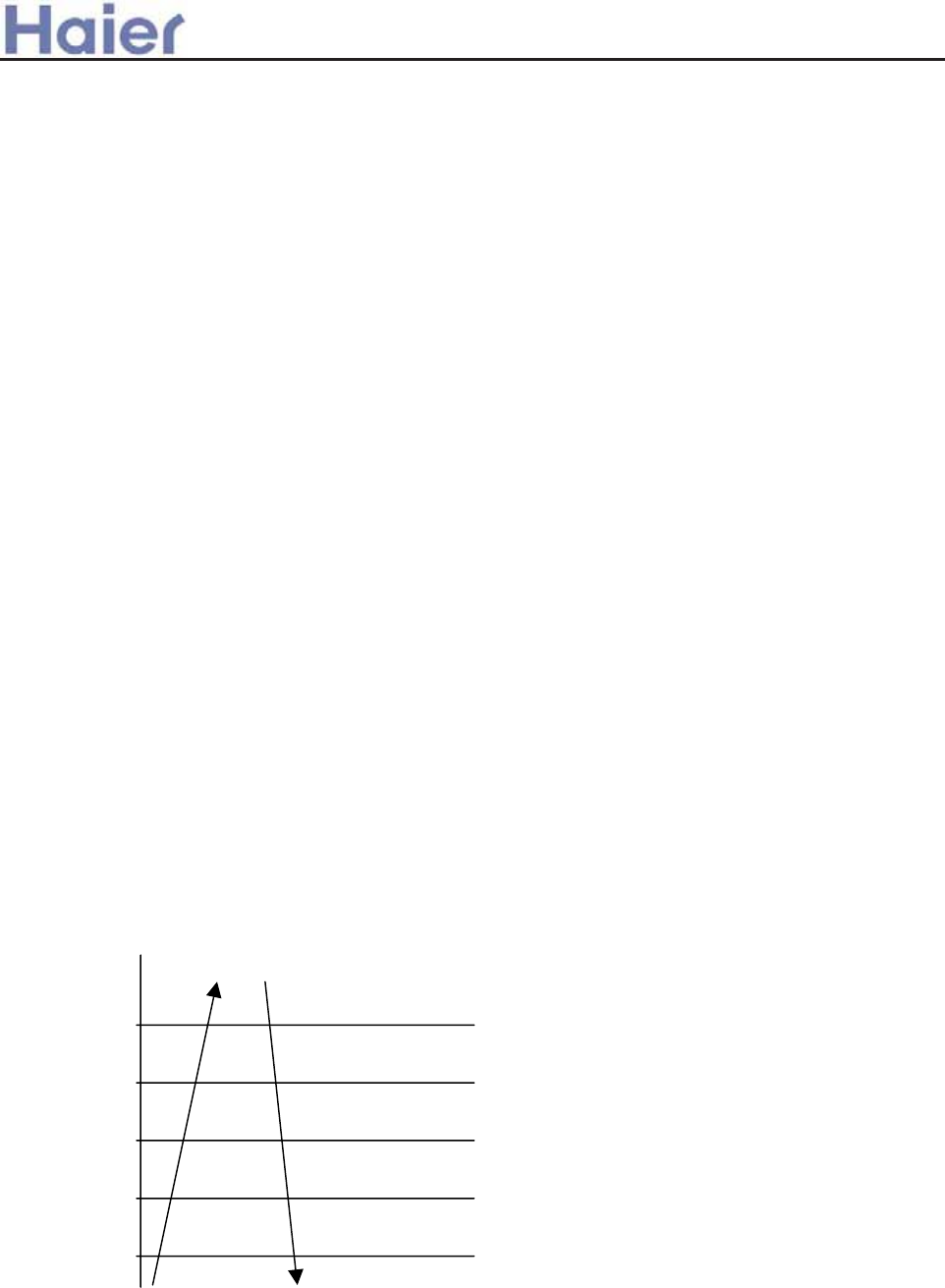
>a__WcU[S^<[c>a`V[e[a`Wc
(3): Defrost operation for 9 minutes contineously.
E. If the quit condition can be met, the unit will perform:
Compressor stops, and outdoor motor runs. 50 seconds later the 4-way valve is close, then 60
seconds later, compressor will perform as startup procedure.
F. In defrosting period and in 6 minutes after defrosting, the low pressure is shielded.
7.2.6 PTC output control
z When outdoor unit is electrified, PTC output is 0, 10 seconds later, it is 1.
z After compressor stops for 10 minutes contineously, PTC output is 0.
z When getting the compressor-start signal, firstly PTC output is 1, 5 seconds later,
compressor will start up.
7.2.7 Electric heater control
When shutoff, the electric heater will be controlled by the ambient temperature: below 20ć,
working; over 26ć, stop.
When the unit switched on, electric heater will not work.
7.2.8 Time shorting function, auto-checking function
Time shorting function: If the time shorting port is in short circuit, the unit will perform a 1/60 time
shorting control.
Auto-checking function: When first short-circuit then electrified, enter auto-checking, steps:
failure LED 1-5, EEV, electric herter, oxygen bar, 4-way valve, low speed –high speed wind.
7.2.9 Additional functions
7.2.9.1 The interval between compressor stop to startup again is 3 minutes, which can protection
compressor. If being electrified for the first time, compressor will start up only when the valve opens
to the normal operation angle.
7.2.9.2 TD high temperature protection
As long as the unit is running, the TD discharging overheat protection will work, but the
discharging sensor failure will alarm 4 minutes later after compressor starts up.
Measure sensor value: measure for 100 times (The program performs for one period needs 5
ms, every time the system will take samples for 8 times, and make an order for them, taking out 2
average values in the middle, and make an average value.).
TD˄ć˅ Abnormal stop
117
quick reduce FQY(1HZ/s)
112
slow reduce FQY(1HZ/10s)
108
FQY no change
105
rise FQY(1HZ/10s)
98
rise FQY(1HZ/1s)
TD>117ć and keeps for 20 seconds, discharging temperature over high protection will work,
the unit will stop and alarm(outdoor indicates, not sending to indoor). the TD overhigh protection
occurs 3 times, the unit will stop and alarm (sending to indoor), it can not resume automatically.
7.2.9.3 In heating indoor TC high temperature protection
Indoor heat exchanger temperature will check the indoor coil temperature, if it is over 55ć, the
unit will reduce the compressor motor speed to perform the indoor heat exchanger temperature
-137-
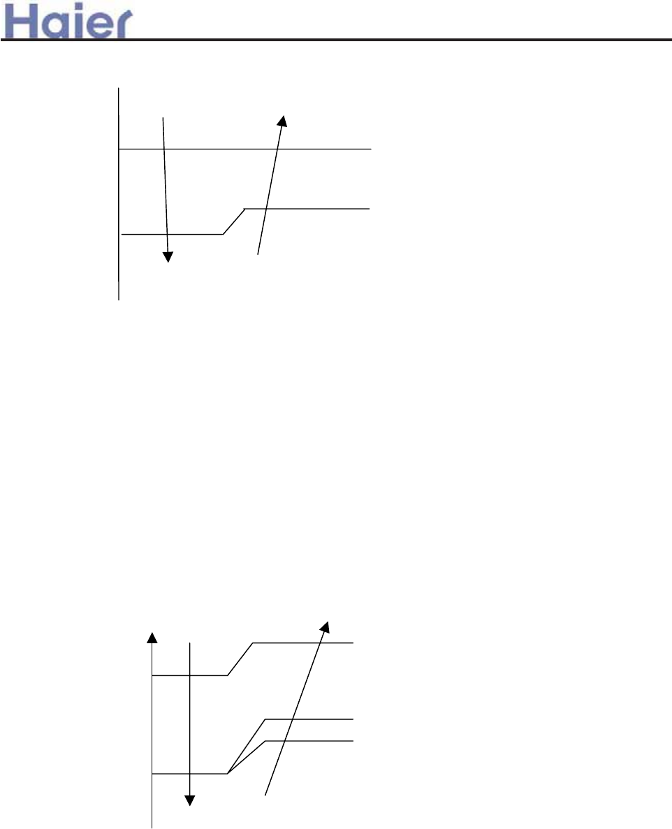
>a__WcU[S^<[c>a`V[e[a`Wc
overhigh protection. If it is below 48ć, the unit will resume to be normal.
TC
P reduce slowly
55
Q remaining
52
48 R rise slowly
P: reduce at the speed of 1Hz/10s
Q: remain the previous value
R: rise at the speed of 1Hz/10s
7.2.9.4 Overcurrent protection(realised by power module)
ƽIn the course of compressor startup, if current is over 13A and keeps for 3 seconds, compressor
will stop and the unit alarms. 3 minutes later, compressor will re-start up, if in 10 minutes, it occurs for
3 times, the unit will stop and alarm.
ƽOvercurrent reducing frequency protection
When current is over (B)A, compressor will reduce frequency at 1HZ/s, and will stop when it is
below (B)A and over (B-1)A, then rise frequency at 1HZ/10s; when current is below (B-1)A, it will
resume the target frequency.
Remarks: Power module frequency limited point: 88ć, if the frequency reduces down to 86ć,
but if it is up to 90ć, the unit will stop and alarm.
7.2.9.5 Indoor heat exchanger anti-freezed protection
11ć
9ć
7ć
6ć
5ć
When TCLJ 5ć, compressor frequency will reduce at 1HZ/10s
When TCbegins to rise up, and 6LJ=TCLJ=7ć, compressor frequency will remain
7.2.9.6 Outdoor temperature limitation
Cool: When outdoor temperature is below 15ć, in cooling, compressor frequency will be limited
below 50Hz, and outdoor fan speed is compusorily Class-1.
Heat: When outdoor temperature is over 20ć, in heating, compressor frequency will be limited
below 50Hz, and outdoor fan speed is compulsorily Class-1.
If the above is AC motor, the compulsory fan speed will be low speed.
7.2.9.7 Rated operation
ƽRated cooling:
-138-
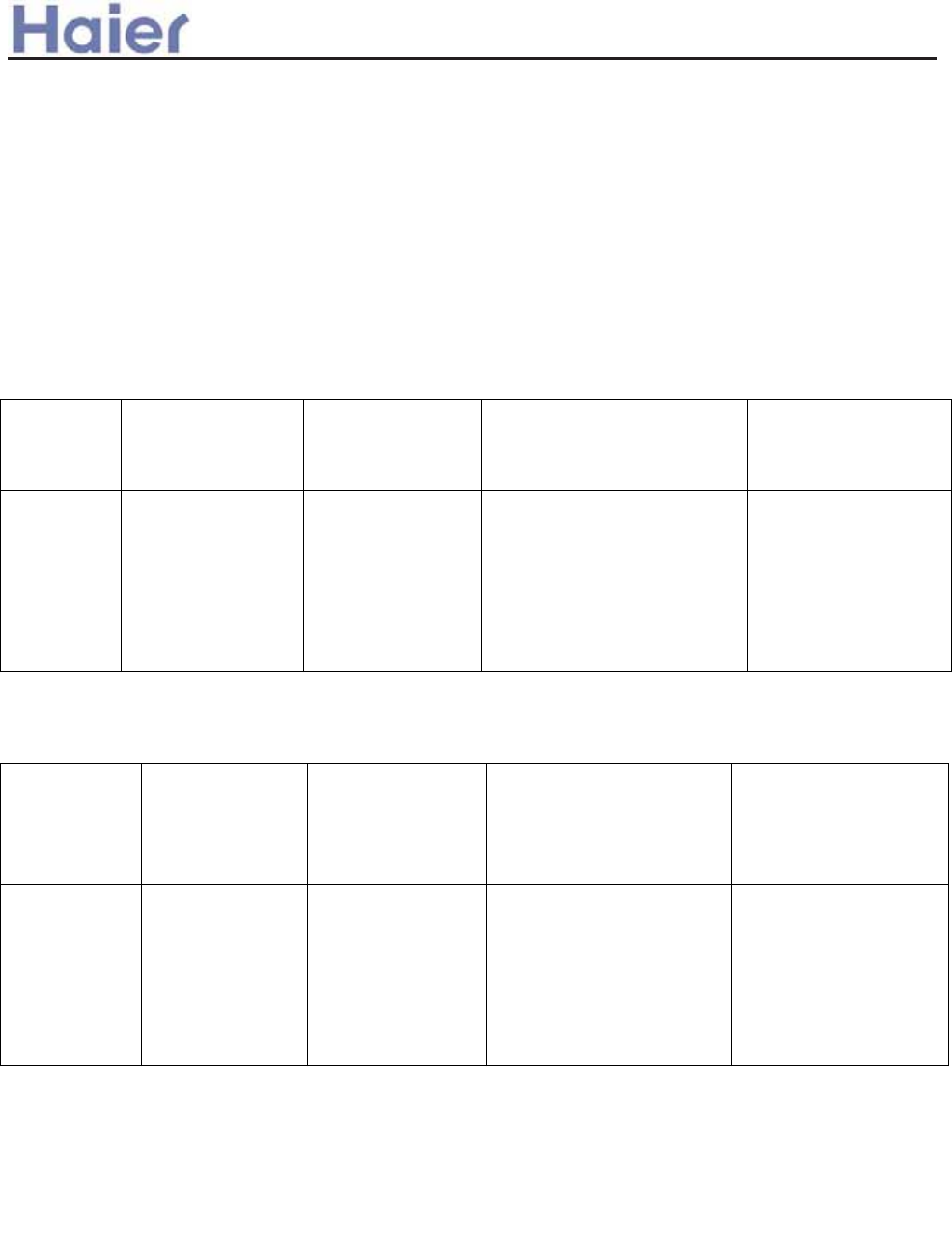
>a__WcU[S^<[c>a`V[e[a`Wc
When receiving the indoor rated operation command, the unit will enter rated cooling operation.
zRated heating:
When receiving the indoor rated operation command, the unit will enter rated cooling operation.
When receiving the indoor min. heating operation command, the unit will enter min. heating
operation.
In rated operation period, the frequency can be adjusted by manual. Once being adjusted by
manual, the unit will not receive the indoor frequency.
7.2.9.8 Outdoor compulsory operation
z Compulsory cooling operation
Put the first bit of dip switch on the indicator board at OFF, the unit will enter compulsory cooling
operation, as follow:
Compressor
startup
Current, discharging
protection and failure
treatment
Operation before
the base open angle
3 minutes later after
compressor is running
Manual adjustment
normal normal Normal 1: fixed base open angle
2: fixed running frequency 60HZ
3: fixed outdoor motor speed:
class-7
1: angle adjusted by
hand
2: frequency adjusted
by hand
3: fan speed adjusted
by hand
z Compulsory heating operation
Put the second bit of dip switch on the indicator board at OFF, the unit will enter compulsory heating
operation, as follow:
Compressor
startup
Current,
discharging
protection and
failure treatment
Operation before
the base open angle
3 minutes later after
compressor is running
Manual adjustment
normal normal Normal 1: fixed base open angle
2: fixed running frequency
50HZ
3: fixed outdoor motor speed:
class-7
1: angle adjusted by
hand
2: frequency adjusted by
hand
3: fan speed adjusted by
hand
7.2.9.9 High pressure switch
3 minutes later after compressor starts up, the system will check the pipe pressure. If the pipe
pressure is over high and high pressure switch acts for over 30 seconds, the compressor and
outdoor motor will stop, 3 minutes later, the unit will resume. If in 30 minutes the unit stops for 3
times because of overhigh pressure, the system will alarm, then compressor will not start up again;
when being electrified after being powered off, the protection will be cancelled.
9.10 Low pressure switch
When compressor stops, if low pressure switch acts for 30 seconds contineously, the unti will
alarm.
When compressor starts up, in 3 minutes, low pressure switch will be shielded.
In defrosting or in 6 minutes after defrosting is over, low pressure switch will be shielded.
7.2.9.11 Failure code and troubleshooting
z Alarm lamp is off when no failure
-139-
>a__WcU[S^<[c>a`V[e[a`Wc
Ensure that alarm indicating time is over 2 minutes and 50 seconds.
(1): Resumable alarm, and will be sent to indoor unit.
(2): Resumable alarm, but if in 30 minutes it occurs 3 times, it can be resumed only when being
electrified after being powered off.
Failure
code
Emission
code
Outdoor
indicator display
Failure description
01 01 00001 Power module IPM protection
02 02 00010 DC fan motor failure DC fan motor failure
03 no 00011 Communication
failure
Outodor alarms, not sends to indoor.
If no communication in 4 minutes, outdoor
shuts off and alarm, the failure can be
resumable.
04 04 00100 Compressor
discharging
temperature too high
Discharging temp. over 117ć, it will confirm
3 times in 30 minutes and then send signal to
indoor.
05 05 00101 Over current AC current overhigh protection or current
transducer broken down.
06 06 00110 Outdoor ambient
temp. sensor failure
Resumable, if sensor is disconnected, alarm
will occur and keeps for 3 minutes, then
resumes due to signal.
07 07 00111 Outdoor coil temp.
sensor failure
Outdoor defrosting sensor, discharging
sensor abnormal
08 08 01000 High pressure switch
failure
Acts 3 times in 30 minutes
09 09 01001 Discharging temp.
sensor failure
Alarm 4 minutes later after starting up,
discharging temperature abnormal
10 10 01010 Power supply over
high/low voltage
Pre-set for 50Hz
11 No No Overload in heating No send signal to indoor
12 No No No No send signal to indoor
13 No No No No send signal to indoor
14 14 01110 Outdoor EEPROM
failure
Outdoor EEPROM failure
15 1 01111 Power module failure Compressor blocked
16 1 10000 Power module failure Compressor heavy vibration
17 1 10001 Power module failure Abnormal compressor startup
18 18 10010 Power module failure Compressor running faulty
19 19 10011 Power module failure Detecting circuit abnormal
20 1 10100 Power module failure Compressor broken down
21 No 10101 Compressor suction
temp. too high—for
the unit with EEV
10 minutes later after startup, measure TS
over 40ć for 5 minutes
22 No 10110 Communication failure
between outdoor PCB
and the module
Not communicate for 4 minutes contineously,
it will alarm
-140-
Corresponding outdoor PCB failure
>a__WcU[S^<[c>a`V[e[a`Wc
23 1 10111 Module malfunction Module temp. over high
24 24 11000 Low pressure switch
failure
Low pressure switch acts for 30 seconds
contineously
No No No Temperature cutoff
protection
1˅Indoor pipe temp. is abnormal, outdoor default cooling temp. : 5ć, heating temp.: 40ć. The
above temperatures are normal.
2˅In defrosting, and in 3 minutes after defrosting is over, if sensor is abnormal, there will not alarm.
3˅Outdoor defrosting temp. sensor: when ambient temp. is below -5ć, detect after having start for 3
minutes.
7.2.9.12 Backup operation
Outdoor TC failure treatment: outdoor LED alarms, but the failure code will not be sent to other place,
the outdoor default TC is as follow: cooling temperature, 5ć; heating temperature, 40ć.
7.2.9.13 Special functions
1) Power operation
When receiving the Power operation signal from indoor, the unit will operate as the set
frequency by EEPROM. Fan speed will depend on the ambient temperature and the frequency.
When the Power signal is cancelled by indoor, the Power operation will stop.
2) Soft operation
When receiving the Soft operation signal from indoor, the unit will operate as the set frequency
by EEPROM. Fan speed will depend on the ambient temperature and the frequency. When the Soft
signal is cancelled by indoor, the Soft operation will stop.
3) Time shorting operation
When receiving the time shorting signal, the unit will perform the 1/60 time shorting operation.
4) Compulsory cooling operation
When receiving the compulsory cooling signal from indoor unit, the unit will execute the
compulsory cooling operation at the frequency sent from indoor. Only discharging temperature
protection and current protection are valid, all the other protections are invalid.
5) Oxygen bar: start after receive indoor oxygen bar signal, the outdoor motor should run at 1-class
speed when compressor stop.
6) Manual defrosting
When receiving the manual defrosting signal from indoor, the unit will enter the defrosting
operation immediately. The interval between two manual defrosts is at least 3 minutes. If the
communication protoco has not the set, this function is not available.
7) Rated, Middle, Minimal operation
When receiving the rated/middle/minimal operation signal from indoor, the unit will operate at
the frequency and fan speed set by EEPROM, meanwhile, all the protections are valid.
7.2.9.14 Outdoor indicator
Five-indicator combination shows the failure code.
4-bit dip switch: the normal position is ON.
First bit: OFF, compulsory cooling.
Second bit: OFF, compulsory heating.
Third bit: OFF, backup operation (outdoor ambient temp.).
Fourth bit: OFF, DC fan motor (ON, AC fan motor).
-141-
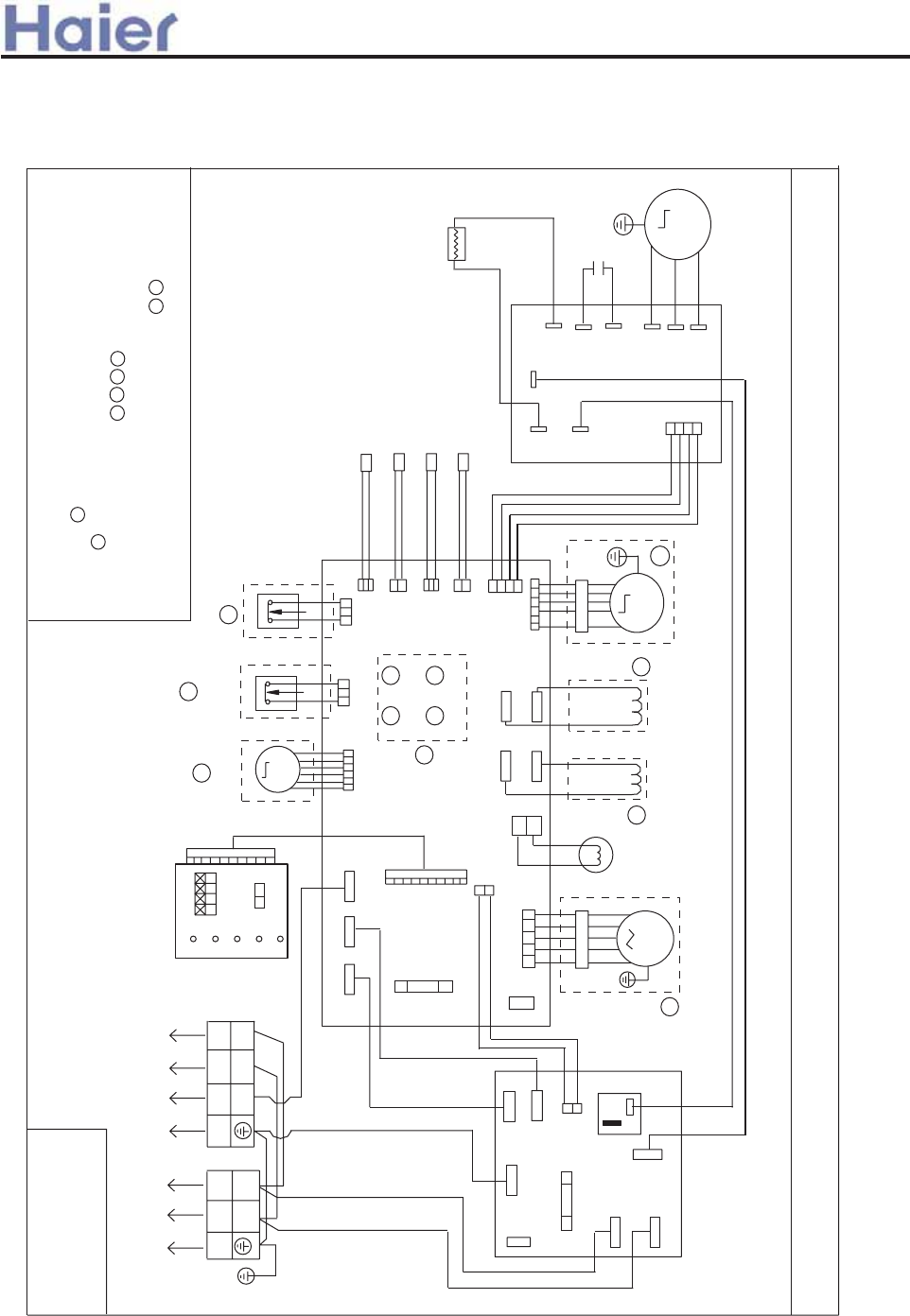
8.1 Inverter outdoor unit
>a__WcU[S^<[c>a`V[e[a`Wc
AU182AFERA, AU242AGERA
8 Electrical wiring diagram and PCB photo
Note: the PCB code for AU182AFERA and AU242AGERA is 0010452040.
-142-
REACTOR
ELECTROLYTIC
CAPACITOR
RO
NOTES:
1.DASHED PARTS ARE JUST CAN SELECT ONE BETWEEN
THIS TWO FAN MOTOR,AND DIFFERENT TYPE HAVE DIFFERENT MOTOR
2.PARTS IN DASHED FRAMES ARE OPTIONAL
3.USER SHOULD NOT TO PRESS SW1-4 IN DASHED FRAME
6.USER SHOULD NOT TO CHANG THE DIP SWITCH SW5 ON LED BOARD
5.THE LED1-5 ON LED BOARD ARE USED FOR ERROR ALARM
COMPRESSOR INHALE SENSOR
DEFROST TEMP.SENSOR
LOW PRESSURE
SWITCH
AMBIENT TEMP. SENSOR
HIGH PRESSURE
SWITCH
M
EEV
CN17
CN16
CN10
CN3
PP
CN15
CN14
CN13
CN11
CN12
SW3SW1
SW2 SW4
POWER SUPPLY
TO INDOOR UNIT
N(in)
CN2
W
W
W
W
W
Y/G
Y/G
R
B
B
B
B
B
CN1
L(in)
Sig
CN21
CN19
CN25
CN8
PTC
RL1
),/7(5%2$5'
1
2
3
L
N
CN2
CN7
CN6
CN3
CN1
220VAC-N
220VAC-L
0$,1%2$5'
CN9 CN4
CN5
CN8
AC FAN
MOTOR CAP.
WIRING DIAGRAM OF OUTDOOR UNIT
0010576606
4-WAY
VALVE
COMPRESSOR VENT SENSOR
ON
SERIAL
CN25
SW5
/('%2$5'
LED3
LED4
LED5
14
3
4
3
5
12
34 6
7
5
8
1
2
LED1
LED2
AC FAN MOTOR
DC FAN MOTOR
M
63'8
02'8/(
ACL
ACN
OR
OR
OR
BL
P(+)
N(-)
CN10
B:BLACK
BL:BLUE
W:WHITE R:RED
Y/G:YELLOW/GREEN
TEMP.:TEMPERATURE
Y/G
M
M
VV
DC COMPRESSOR
RI
W
W
U
U
OR:ORANGE
B
W
R
2
4.AUXILIARY CRANKCASE HEATER IN DASHED FRAME ARE OPTIONAL
8
CN6
CN7
CRANKCASE
HEATER
67
CN26
CN27
CRANKCASE
AUXILIARY
HEATER
T3.15A - 250VAC
T25A 250VAC
FUSE1 FUSE
FUSE1
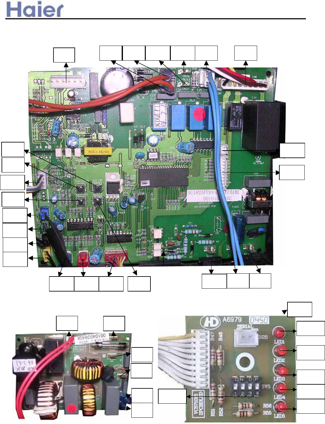
>a__WcU[S^<[c>a`V[e[a`Wc
Outdoor main control board 0010452040
CN9 CN8CN26CN27CN7CN6
CN3
CN10
CN11
CN12
CN13
CN14
CN16 CN15 CN17 CN21 CN1 CN2
SW3
SW1
SW2
SW4
CN19
CN25
CN8 CN2
CN1
CN5
CN4
CN3
LED5
LED1
LED2
LED3
LED4
SW05
CN25
SW05 is used for factory quality control engineers, the default position is: OFF OFF OFF ON
for AU182AFERA, as for AU242AGERA, the default position is: OFF OFF OFF OFF, for the above
models, there are also module board 0010403555.
Outdoor filter board 0010403645 Outdoor indicator board 010452047
-143-
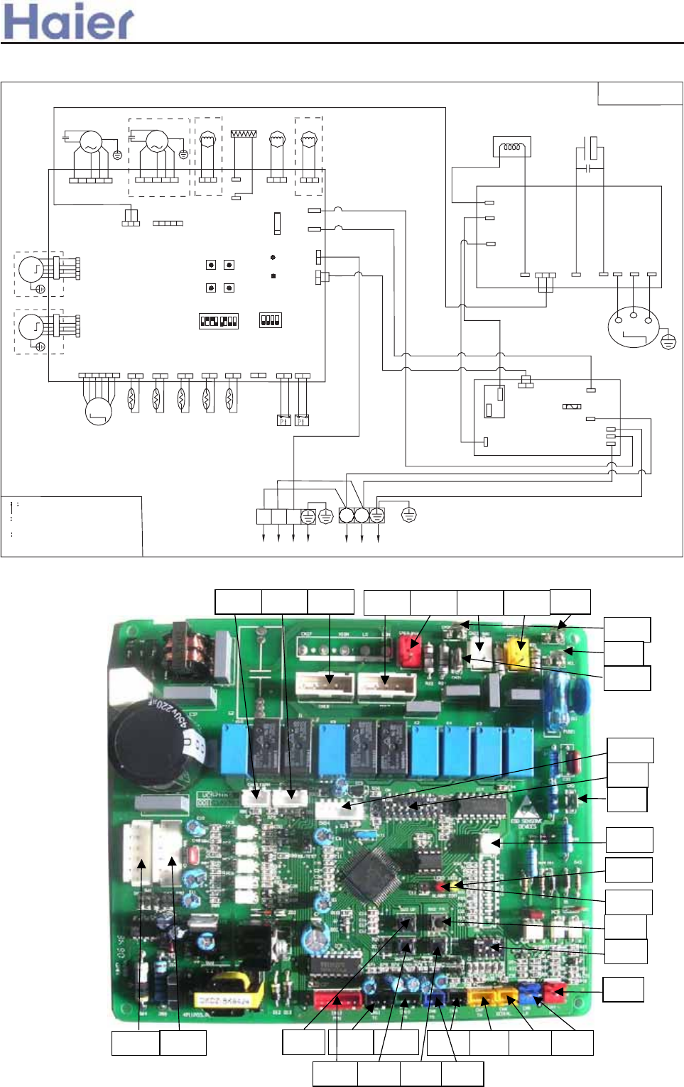
>a__WcU[S^<[c>a`V[e[a`Wc
N
L
M
LED2
LED1
CN25
CRANKCASE
HEATER
CN3
4-WAY
VALVE
AC FAN 2 MOTOR
W
U
COMPRESSOR
V
CN1
2
1
T25A 250VAC
FUSE
M
To Power Supply
250VAC T5A
FUSE1
2.USER SHOULD NOT TO CHANGE THE DIP
SWITCH SW1,SW6.
1.DESHAED FRAMES ARE OPTIONAL, AND IN
SOME MODELS ARE NOT AVAILABLE.
NOTE:
CN20
NLM
CN12
PMV
SV2
CN19
ON
PTC
SIG
CN1
N
SW4 SW5
SW2SW3
FA
B : BLACK
R : RED
OR : ORANGE
W : WHITE
Y/G : YELLOW/GREEN
H
CN17
CN21
CN2
L
CN22
CN14
CN2
CN5
CONTROL
CIRCUIT
BOARD
CN4
CN3
CN8
CN7
CIRCUIT
BOARD
POWER
UVW
R
T/RB
S
P1
N(-) P(+)
+-
ISPM
Y/G
ORBL
BL : BLUE
CAPACITOR
capacitor
REACTOR
SW1
12345678
CN13
TO ISPM
To Indoor Unit
<*
5
%
:
%
:
5:%
CN4
HPLP
CN5
CN6
CN7CN8
CN9CN10CN11
TC TS TD TE TA
SERIAL
CN15
DC FAN MOTOR
M
CN16
DC FAN MOTOR
M
M
AC FAN 1 MOTOR
NLMH
CN18
capacitor
SV1
CN23
SPDU
SW6
ON
4321
FAN
UP
DOWN COM
ALARM
5
3
Y/G
<*
:%
0150500546
CIRCUIT DIAGRAM OF OUTDOOR UNIT
AU362AHERA
CN18 CN17 CN19
CN14CN13 CN22 CN23 CN1
CN20
CN2
CN21
CN3
CN25
LED1
LED2
SW1
CN24
SW2
SW6
CN4
CN5CN6CN7
SW5
CN8
CN10
CN9SW4
CN11
CN12
SW3
CN16
CN15
Outdoor PCB 0010452929
-144-
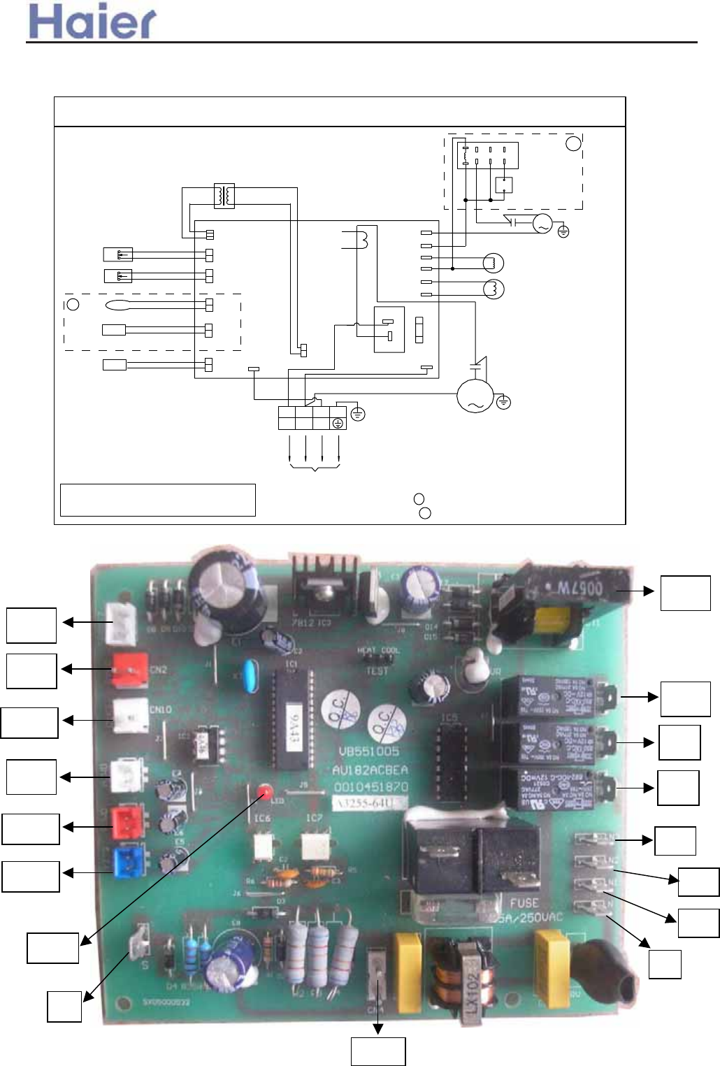
8.2 Fixed frequency outdoor unit
AU182AEEAA
TO INDOOR UNIT
Y/G
B
W
R
2
1
3
Y/G
N
CN4
OUTDOOR AMBINENT SENSOR
COMPRESSOR VENT SENSOR
OUTDOOR PIPING SENSOR
LOW PRESSURE SWITCH
HIGH PRESSURE SWITCH
S
CN11
CN12
CN3
CN1
CN10
CN2
TRANS.
CIRCUIT
DETECTOR
FUSE
FAN MOTOR
W
W
B
B
W
FAN MOTOR
SPEED
CONTROLLER
4-WAY VAVLE
WIND
GR
M
NC
COM
RELAY
NO
2
FAN MOTOR CAP.
NOTE:
1
M
COM
NO
CRANK
HEATER
FAN
N3
N2
ST
BL
BL
BL
CIRCUIT DIAGRAM OF OUTDOOR UNIT
0010573313
W
R
B
R
S
C
Y/G
T3.15A/250VAC
1
3
5
7
8
642
COMPRESSOR
R:RED W:EHITE GR:GREY
BL:BLUE B:BLACK Y/G:YELLOW/GREEN
P
P
HB
N1
1. DASHED PARTS 1 IS NOT AVAILABLE IN ONLY COOLING TYPE
2. DASHED PARTS 2 IS OPTIONAL FOR LOW AMBIENT TEMP
>a__WcU[S^<[c>a`V[e[a`Wc
0010451870E
CN2
CN3
CN10
ST
FAN
CT1
HB
CN1
CN11
CN12 N3
N2
N
N1
CN4
LED
S
-145-
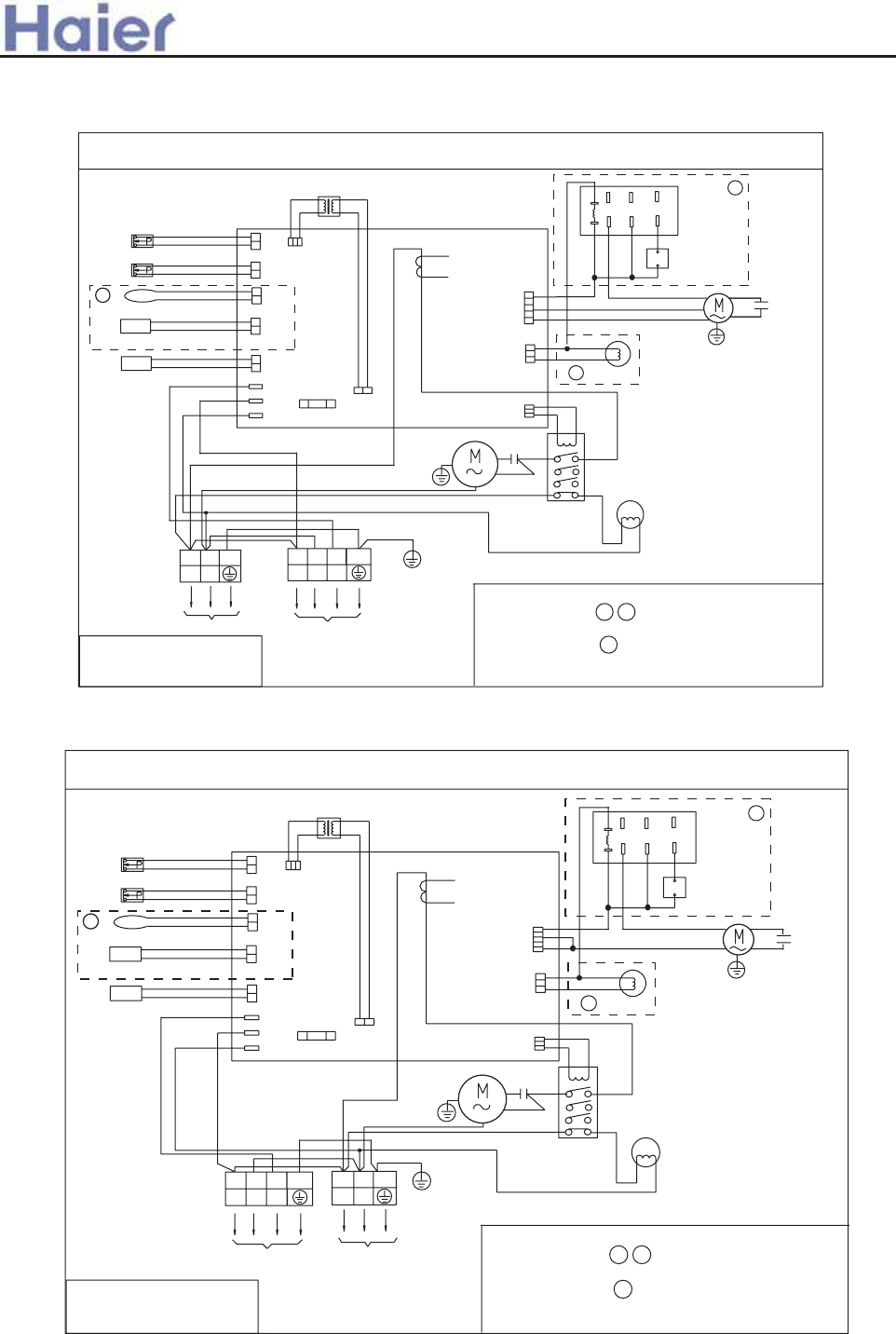
AU242AGEAA
TO INDOOR UNIT
Y/G
B
W
W
123
R
L1
N
CN4
CN7
OUTDOOR AMBINENT SENSOR
DISCHARGE SENSOR
OUTDOOR PIPING SENSOR
LOW PRESSURE SWITCH
HIGH PRESSURE SWITCH
S
CN11
CN12
CN3
CN10
CN2 CN1
TRANS.
CT
MAGNETIC
CONTACTOR
T3.15A/250VAC
FUSE
FAN MOTOR
B
CN9
CN5
R
B
BL
FAN MOTOR
SPEED
CONTROLLER
GR
NO
COM
RELAY
3
1
3
5
7
2
4
6
8
NC
FAN
MOTOR
CAP.
Y/G
NOTE:
1. DASHED PARTS 1 2 IS NOT AVAILABLE IN ONLY
COOLING TYPE
CIRCUIT DIAGRAM OF OUTDOOR UNIT
L
N
W
B
Y/G
Y/G
POWER SUPPLY
R:RED W:WHITE
BL:BLUE GR:GRAY
B:BLACK
Y/G:YELLOW/GREEN
4-WAY VAVLE
SOLENOID
2
W
W
R
B
R
S
C
W
Y/G
COMPRESSOR
CRANK CASE
HEATER
1
B
R
2. DASHED PARTS 3 IS OPTIONAL IN LOW AMBIENT
TEMP. COOLING TYPE, AND THERE IS NO FAN
MOTOR SPEED CONTRLLER IN NORMAL TYPE
BL
B
B
>a__WcU[S^<[c>a`V[e[a`Wc
-146-
AU282AHEAA
TO INDOOR UNIT
Y/G
B
W
W
123
R
L1
N
CN4
CN7
OUTDOOR AMBINENT SENSOR
DISCHARGE SENSOR
OUTDOOR PIPING SENSOR
LOW PRESSURE SWITCH
HIGH PRESSURE SWITCH
S
CN11
CN12
CN3
CN10
CN2 CN1
TRANS.
0010573314
CT
MAGNETIC
CONTACTOR
T3.15A/250VAC
FUSE
FAN MOTOR
B
CN9
CN5
R
B
BL
FAN MOTOR
SPEED
CONTROLLER
GR
NO
COM
RELAY
3
1
3
5
7
2
4
6
8
NC
FAN
MOTOR
CAP.
Y/G
NOTE:
1. DASHED PARTS 1 2 IS NOT AVAILABLE IN ONLY
COOLING TYPE
CIRCUIT DIAGRAM OF OUTDOOR UNIT
L
N
W
B
Y/G
Y/G
POWER SUPPLY
R:RED W:WHITE
BL:BLUE GR:GRAY
B:BLACK
Y/G:YELLOW/GREEN
4-WAY VAVLE
SOLENOID
2
WW
W
R
B
R
S
C
W
Y/G
COMPRESSOR
CRANK CASE
HEATER
1
B
R
2. DASHED PARTS 3 IS OPTIONAL IN LOW AMBIENT
TEMP. COOLING TYPE, AND THERE IS NO FAN
MOTOR SPEED CONTRLLER IN NORMAL TYPE
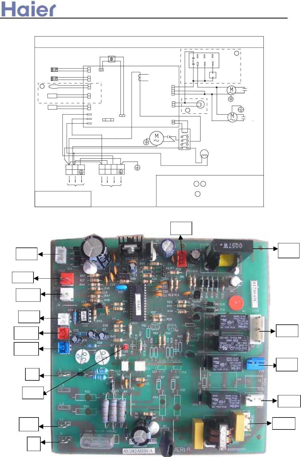
0010452442E
CN8
CN2
CN3
CN10
CN9
CT1
CN7
CN1
CN12
CN5
CN11
S
L1
N
LED
CN4
>a__WcU[S^<[c>a`V[e[a`Wc
TO INDOOR UNIT
Y/G
B
W
W
123
R
L1
N
CN4
CN7
OUTDOOR AMBINENT SENSOR
DISCHARGE SENSOR
OUTDOOR PIPING SENSOR
LOW PRESSURE SWITCH
HIGH PRESSURE SWITCH
S
CN11
CN12
CN3
CN10
CN2 CN1
TRANS.
CT
MAGNETIC
CONTACTOR
T3.15A/250VAC
FUSE
FAN MOTOR
B
CN9
CN5
R
B
BL
FAN MOTOR
SPEED
CONTROLLER
GR
NO
COM
RELAY
3
1
3
5
7
2
4
6
8
NC
FAN
MOTOR
CAP.
Y/G
NOTE:
1. DASHED PARTS 1 2 IS NOT AVAILABLE IN ONLY
COOLING TYPE
CIRCUIT DIAGRAM OF OUTDOOR UNIT
L
N
W
B
Y/G
Y/G
POWER SUPPLY
R:RED W:WHITE
BL:BLUE GR:GRAY
B:BLACK
Y/G:YELLOW/GREEN
4-WAY VAVLE
SOLENOID
2
W
W
R
B
R
S
C
W
Y/G
COMPRESSOR
CRANK CASE
HEATER
1
B
R
2. DASHED PARTS 3 IS OPTIONAL IN LOW AMBIENT
TEMP. COOLING TYPE, AND THERE IS NO FAN
MOTOR SPEED CONTRLLER IN NORMAL TYPE
B
B
FAN
MOTOR
FAN
MOTOR
CAP
Y/G
W
AU362AIEAA
-147-
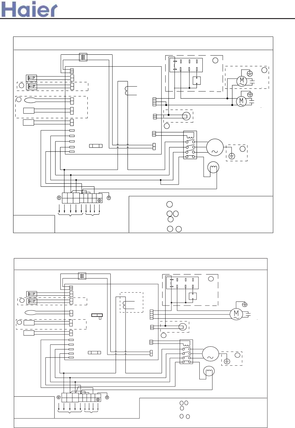
>a__WcU[S^<[c>a`V[e[a`Wc
CIRCUIT DIAGRAM OF OUTDOOR UNIT
0010573510
B:BLACK
BL:BLUE
TO INDOOR UNIT
HIGH PRESSURE SWITCH
LOW PRESSURE SWITCH
OUTDOOR PIPING SENSOR
COMPRESSOR VENT SENSOR
OUTDOOR AMBINENT SENSOR
Y/G:YELLOW/GREEN
R:RED
CN2
CN10
CN1
CN3
CN12
CN11
POWER SUPPLY
W
W:WHITE
R
BL
B
R
R
S
W
T
BL
R
N
S
L2
L1
L3
W
N
1
B
2
B
Y/G
Y/G
3
R
T3.15A/250VAC
FUSE
TRANS.
NOTE:
FAN MOTOR
FAN
MOTOR
CRANK CASE
HEATER
2
4
6
8
B
CN4
CN9
CN7
CN5
W
R
B
BL
B
Y/G
COMPRESSOR
4-WAY
VALVE
SOLENOID
R
W
GR
M
NO
7
COM
53
NC
1
FAN
MOTOR
CAP
FAN
MOTOR
CAP
2
5
CT
1
3
6
4
Y/G
Y/G
1. DASHED PARTS 1 IS NOT AVAILABLE IN COOLING CAPACITY BELOW
36000Btu
2. DASHED PARTS 2 3 IS NOT AVAILABLE IN ONLY COOLING TYPE
3. DASHED PARTS 4 IS OPTIONAL FOR LOW AMBIENT TEMP. COOLING,
AND THERE IS NO FAN MOTOR SPEED CONTRLLER IN NORMAL TYPE
4. DASHED PARTS 5 6 ARE NOT AVAILABLE IN SOME TYPE
FAN MOTOR
SPEED
CONTROLLER
MAGNETIC CONTACTOR
AU28NAHEAA, AU36NAIEAA, AU48NAIEAA, AU60NAIEAA
CIRCUIT DIAGRAM OF OUTDOOR UNIT
0150500023
B:BLACKBL:BLUE
GR:GRAY
TO INDOOR UNIT
HIGH PRESSURE SWITCH
LOW PRESSURE SWITCH
OUTDOOR PIPING SENSOR
COMPRESSOR VENT SENSOR
OUTDOOR AMBIENT SENSOR
Y/G:YELLOW/GREEN
R:RED
CN2
CN10
CN1
CN3
CN12
CN11
POWER SUPPLY
W
W:WHITE
R
BL
B
B
R
S
T
R
N
S
10P
5P
SW1
L2
L1
L3
N
1
2
Y/G
3
T3.15A/250VAC
FUSE
TRANS.
NOTE:
FAN MOTOR
CRANKCASE
HEATER
2
4
6
8
B
CN4
CN9
CN7
CN5
R
B
Y
R
BL
BL
BL
B
Y/G
COMPRESSOR
4-WAY
VALVE
SOLENOID
R
R
S
T
W
GR
M
NO
7
COM
53
NC
1
FAN
MOTOR
CAP
1
4
CT
2
5
3
Y/G
1. DASHED PARTS 1 2 ARE NOT AVAILABLE IN ONLY COOLING TYPE
5.
FOR COOLING CAPACITY IS 52000BTU TYPE
,THE LINE THROUGH CT IS ONE CIRCUIT,
FOR COOLING CAPACITY IS 42000BTU 36000BTU AND 28000BTU TYPES
,THE LINE THROUGH CT IS TWO CIRCUITS.
2. DASHED PART 3 IS OPTIONAL FOR LOW AMBIENT TEMP. COOLING,
AND THERE IS NO FAN MOTOR SPEED CONTRLLER IN NORMAL TYPE
3. DASHED PARTS 4 5 ARE NOT AVAILABLE IN SOME TYPE
4. FOR COOLING CAPACITY IS 52000BTU AND 28000BTU TYPES,THE DIP SWITCH SW1 IS ON 5P SIDE,FOR COOLING CAPACITY IS 42000BTU AND 36000BTU TYPES,THE DIP SWITCH SW1 IS ON 10P SIDE.
FAN MOTOR
SPEED
CONTROLLER
MAGNETIC CONTACTOR
AU42NALEAA
-148-
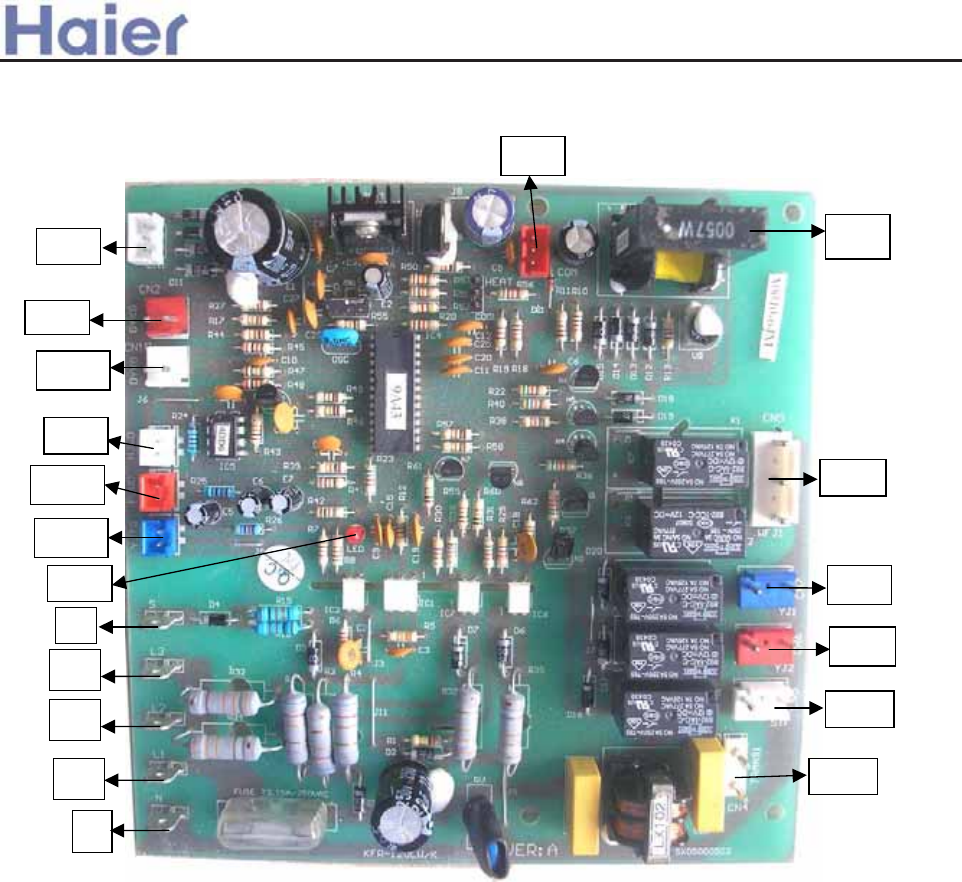
>a__WcU[S^<[c>a`V[e[a`Wc
CN8
CN2
CN3
CN10
CN9
CT1
CN7
CN1
CN12
CN11
S
LED
CN5
L1
N
CN4
L3
L2
CN6
0010452378E
-149-
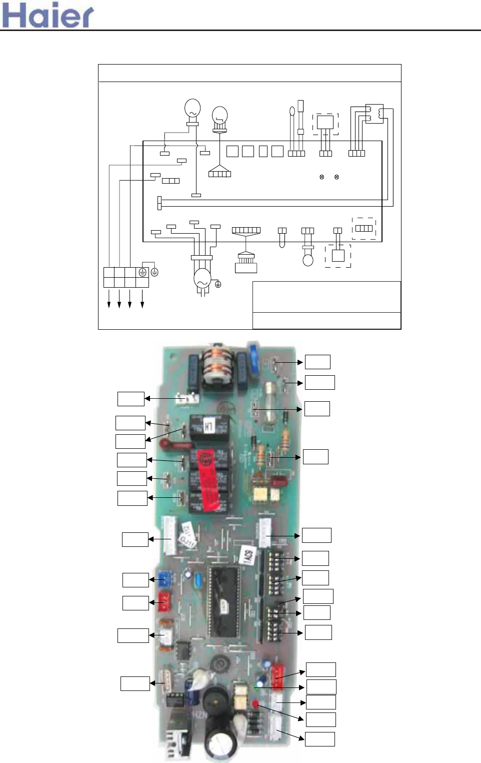
CIRCUIT DIAGRAM OF INDOOR UNIT
0010576971
FUSE1
CN1
TRANS.-I
CN4
S
CN3
NCN2
L
T3.15A/250VAC
CN13
TRANS.-II
CN12
REMOTE
CN10
FLOAT
CN8
ALARM
CN7
RECEVIER
CN6
STEP MOTOR
PIPE ROOM
CN14
CONTROLLER
CN16
CN17
N1
CN18
PUMP
1
Y/G
R
R
YY
B
B
W
W
32
M
WIRED
CONTROLLER
ROOM
TEMP.
SENSOR
PIPING
TEMP.
SENSOR
RECEIVE
BOARD
FLOAT
SWITCH
REMOTE
CENTRALIZED
CONTROLLER
M
PUMP
MOTOR
TRANSFORMER
BM4
BM3 BM2BM1
STEP MOTOR
Y/G
NOTE:
1.THE PARTS IN DASHED FRAME ARE OPTIONAL
2.
REFER TO OPERATION MANUAL TO SET
BM3 AND BM4
3.USER SHOULD NOT TO SET BM1 AND BM2
TO OUTDOOR UNIT
ON
1234
ON
12
ON
1234
ON
1234
LED2 LED1
W:WHITE B:BLACK BR:BROWN BL:BLUE R:RED
Y:YELLOW Y/G:YELLOW/GREED TEMP.:TEMPERATURE
CN11
Itophome
CN15
LOW
MID
HIGH
CN21
CN20 CN22
N2
RY
BL
W
MOTOR
CAPACITOR
M
FAN
MOTOR Y/G
TEMP. SENSOR
AB182ACERA
>a__WcU[S^<[c>a`V[e[a`Wc
8.3 Indoor unit
0010452325E
CN4
CN15
CN17
CN20
CN21
CN22
CN6
CN7
CN8
CN10
CN11
CN12
CN13
CN14
LED1
LED2
BM2
BM1
BM3
BM4
CN19
CN16
CN3
CN1
CN2
CN18
-150-
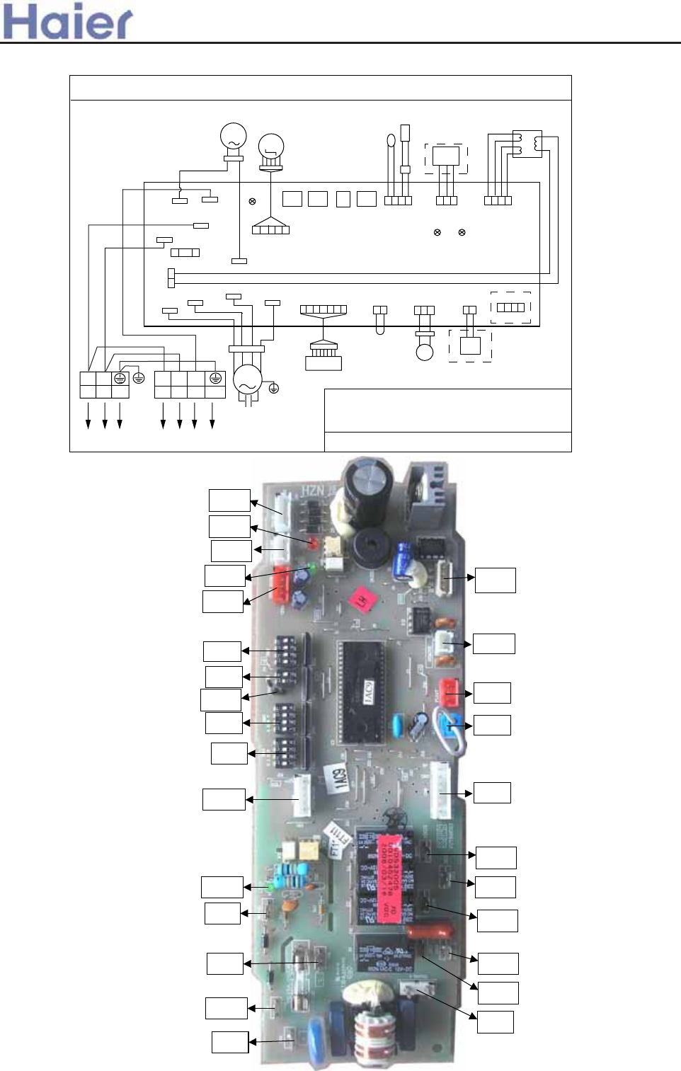
>a__WcU[S^<[c>a`V[e[a`Wc
AB182ACEAA
CIRCUIT DIAGRAM OF INDOOR UNIT
0010576979
FUSE1
CN1
CN15
CN20
LOW
MID
HIGH
CN21 CN22
N2
TRANS.-I
CN4
SIGNAL
LED3
CN3
NCN2
L
T3.15A/250VAC
CN13
TRANS.-II
CN12
CN11
REMOTE
CN10
FLOAT
CN8
ALARM
CN7
RECEVIER
CN6
STEPMOTOR
PIPE ROOM
CN14
CONTROLLER
CN16
CN17
N1
CN18
PUMP
M
WIRED
CONTROLLER
ROOM
TEMP.
SENSOR
PIPING
TEMP.
SENSOR
RECEIVE
BOARD
FLOAT
SWITCH
REMOTE
CENTRALIZED
CONTROLLER
M
PUMP
MOTOR
TRANSFORMER
BM4
ON
1234
ON
12
ON
1234
ON
1234
BM3
BM2
BM1
STEP
MOTOR
1
Y/G
R
R
R Y BL W
B
B
W
W
YY
32
Y/G
Y/G
NOTE:
1.THE PARTS IN DASHED FRAME ARE OPTIONAL
2.
REFER TO OPERATION MANUAL TO SET
BM3 AND BM4
3.USER SHOULD NOT TO SET BM1 AND BM2
W:WHITE B:BLACK BR:BROWN BL:BLUE R:RED
Y:YELLOW Y/G:YELLOW/GREEN TEMP.:TEMPERATURE
LED2 LED1
Y/G
L
BL
BL
BR
BR
N
TO OUTDOOR UNITPOWER SUPPLY
Itophome
MOTOR
CAPACITOR
M
FAN
MOTOR
Y/G
0010452478E
CN13
BM2
CN14
CN6
CN11
CN12
BM1
CN19
LED1
LED2
BM3
BM4
CN16
LED3
CN3
CN1
CN18
CN2
CN4
CN17
CN15
CN20
CN21
CN22
CN7
CN8
CN10
-151-
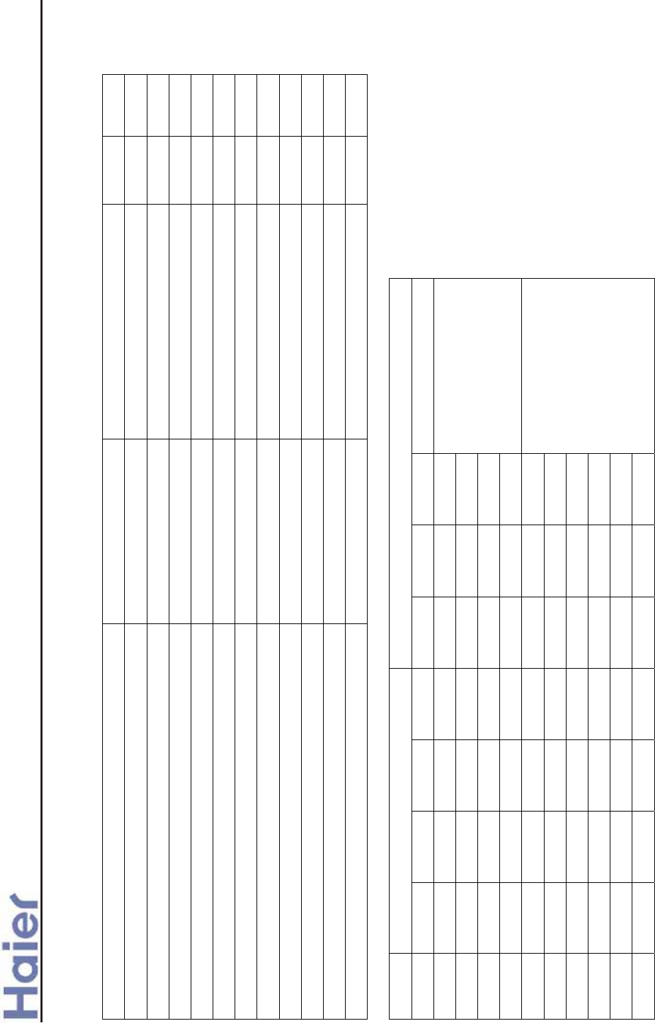
>a__WcU[S^<[c>a`V[e[a`Wc
Jumper selection (Ĝshows jumper connected, ON; hshows jumper disconnected, OFF; * shows no limitation)
Time shorting switch CN7 Emergency switch SW1(receiver) BM1(1) BM1(2)
Time shorting switch Time shorting * * *
Emergency switch * Emergency * *
No outdoor PCB * * hh
With outdoor PCB, fixed speed single split unit * * Ĝh
With outdoor PCB, fixed speed multi split unit * * hĜ
With outdoor PCB, inverter single split unit * * ĜĜ
Inverter unit selection BM2(1) BM2(2) BM2(3) BM2(4)
Temp. compensation 4ć available/not available Ĝ/h* * *
Wired control/ infrared control * Ĝ/h* *
Cooling only/heatpump * * Ĝ/h*
Master/slave wired controller * * * Ĝ/h
Network address selection (Ĝshows jumper connected, ON; hshows jumper disconnected, OFF)
BM4 BM3
address 1 2 3 4 1 2 3 4
1h h h h h h h
2Ĝ h h h h h h
3h Ĝ h h h h h
4Ĝ Ĝ h h h h h
hshows no network
home appliance
5h h Ĝ h h h h
6Ĝ h Ĝ h h h h
ĂĂ ĂĂ ĂĂ ĂĂ ĂĂ ĂĂ ĂĂ
126 Ĝ h Ĝ Ĝ Ĝ Ĝ Ĝ
127 h Ĝ Ĝ Ĝ Ĝ Ĝ Ĝ
128 Ĝ Ĝ Ĝ Ĝ Ĝ Ĝ Ĝ
Ĝwith network home
appliance
0010452325E / 0010452478E information - function selection
-152-

>a__WcU[S^<[c>a`V[e[a`Wc
CIRCUIT DIAGRAM OF INDOOR UNIT 0010576547
(FREEZE)
CN8
SW2
BL
P13
(HUMI)
(PUMP)
(HEAT)
Y
(L)
(FRESH)
P8 P9
P7
P12
P10
P11
(COMM)
W
(N')
(M)
(H)
SW3
P17
(L')
P14
P15
SW5
SW4
P16
CN4
CN5
CN1
TRANS.
SWITCH
(DOOR)
(CONTROLLER)
WIRED
CONTROLLER
(FLOAT)
CN15
CN13
(UP-DOWN)
CN14
AB
(ALARM)
CN16
(REMOTE)
CN11
CN12
FLOAT
REMOTE
RECEIVER
ON
12
ON
1234
CN19
UP-DN L-R
CN20
3
W:WHITE B:BLACK
R:RED Y:YELLOW
OR:ORANGE BL:BLUE
BR:BROWN
Y/G:YELLOW/GREEN
CAP.:FAN MOTOR CAPACITOR
TRANS.:TRANSFORMER
(RECEIVE
BOARD)
(SWING)
(OXYGEN)
OR
YY
M
SWING
MOTOR
FAN MOTOR
2
12
1
5
8
9
7
CN21
CN7
FUSE
T3.15A/250VAC
P4(N2)
M
P5(N3)
TO OUTDOOR UNIT
R
231
B
W
W
R
B
W
B
OR
P1(L)
P2(N)
P3(N1)
MOTOR
MOTOR
SWING
PUMP
R
P6(N4)
SW1
(ROOM/PIPE)
CN6
TEMP.
SENSOR
SENSOR
PIPING TEMP.
ROOM
6
4
Y/G
Y/G
10
14
13
MM
CAP.
Y/G
Y/G
M
11
CAP.
M
ON
1234
ON
1234
ON
1234
6.
PARTS AND CONNECTED WIRES IN DASHED FRAME
12 13 ONLY AVAILABLE IN AC***AFBEA TYPE
7. REFER TO OPERATION MANUAL TO SET SW1-SW5
1. PARTS 1 2 3 IN DASHED FRAME ARE NOT AVAILABLE
2. PARTS 4 5 6 ARE OPTIONAL, AND THE LINE MARKED 14 ONLY AVAILABLE IN CONVERTIBLE TYPE
3. PARTS AND CONNECTED WIRES IN DASHED FRAME 7 9 ARE NOT AVAILABLE IN CONVERTIBLE TYPE,
AND CORRESPONDINGLY THERE IS A CLIP ON PCB
4. PARTS AND CONNECTED WIRES IN DASHED FRAME 8 ARE NOT AVAILABLE IN DUCT TYPE
5. PARTS AND CONNCETED WIRES IN DASHED FRAME 10 11 DETERMINED BY PRODUCTS TYPE
CN17
(12V/ALM)
NOTE:
REMOTE
CONTROLLER
CENTRALIZED
AC182/242ACERA, AC182/242ACEAA, AD182AMERA, AD182ALEAA
CIRCUIT DIAGRAM OF INDOOR UNIT 0010576546
(FREEZE)
CN8
SW2
BL
P13
(HUMI)
(PUMP)
(HEAT)
Y
(L)
(FRESH)
P8 P9
P7
P12
P10
P11
(COMM)
W
(N')
(M)
(H)
SW3
P17
(L')
P14
P15
SW5
SW4
P16
CN4
CN17
CN5
MOTOR
FILTER
CN1
TRANS.
SWITCH
(DOOR)
(CONTROLLER)
(FLOAT)
CN15
CN13
(UP-DOWN)
(12V/ALM)
CN14
AB
(ALARM)
CN16
(REMOTE)
CN11
CN12
FLOAT
REMOTE
RECEIVER
REMOTE
CN2
P
CN1
MC1
COM
MC2
N
ON
12
ON
1234
CN19
CN20
3
W:WHITE B:BLACK
R:RED Y:YELLOW
OR:ORANGE BL:BLUE
BR:BROWN
Y/G:YELLOW/GREEN
TRANS.:TRANSFORMER
FG
L
CONTROLLER
CENTRALIZED
R
BL
B
B
W
FUSE T2.0A/250VAC
(RECEIVE
BOARD)
(SWING)
(OXYGEN)
OR
YY
M
SWING
MOTOR
M
FAN
MOTOR
M
2
11
1
4
8
79
10
CN21
CN7
FUSE
T6.3A/250VAC
T3.15A/250VAC
P4(N2)
POWER SUPPLY
M
P5(N3)
TO OUTDOOR UNIT
R
23
1
B
W
L
BR
BL
N
Y/G
W
R
B
W
B
Y/G
OR
P1(L)
P2(N)
P3(N1)
FAN CAP.
Y/G
MOTOR
MOTOR
M
SWING
PUMP
R
P6(N4)
SW1
@
@
12
(ROOM/PIPE)
CN6
TEMP.
SENSOR
SENSOR
PIPING TEMP.
ROOM
6
5 13
M
M
ON
1234
ON
1234
ON
1234
?
6. IN AC242ACBEA/AC242ACEAA, DASHED LINES MARKED @
CONNECTED
TO "1 , 2" ON TERMINAL BLOCK, AND THERE ARE NO
LINES BETWEEN "1 AND L" , "2 AND N".
IN *******BIA OR ******ERA TYPE,THE POWER SUPPLY COME FROM OUTDOOR UNIT,
AND THE FUSE TYPE IS T3.15A/250VAC
7.ABOUT THE TERMINAL BLOCK,MARK "BL" IS EQUAL "B" AND THE "BR" IS EQUAL "W".REFER TO OPERATION MANUAL TO SET SW1-SW5
NOTE:
1. PARTS 1 2 3 ARE NOT
AVAILABLE
2. PARTS 4 5 6 ARE
OPTIONAL, AND THE LINE
MARKED 13 ONLY AVAILABLE
IN CONVERTIBLE TYPE
3. PART 7 NOT AVAILABLE
IN DUCT TYPE
4. PARTS AND CONNECTED
WIRES IN DASHED FRAME 8
ONLY FOR AB14/182ACBEA
5.PARTS AND CONNECTED WIRES IN DASHED FRAME 9 10 ARE NOT AVAILABLE IN AD14/182AMBEA, AND IN
CONVERTIBLE TYPE,
CORRESPONDINGLY THERE IS A CLIP ON PCB.
PARTS AND
CONNECTED
WIRES IN DASHED FRAME 11 ONLY FOR
AC142/182/242ACBEA/AC
242ACEAA
TYPE .PARTS AND
CONNECTED
WIRES IN DASHED FRAME 12 DETERMINED BY
PRODUCTS TYPE.
WIRED
CONTROLLER
AB242/362ACERA, AB242/282/482/602ACEAA, AC282/362/482/602AFEAA, AD242ALERA, AD242ALEAA,
AD242/282/362/482AMEAA, AD242/362AMERA, AB362ACERA
-153-
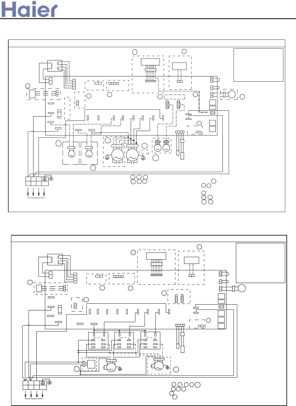
CIRCUIT DIAGRAM OF INDOOR UNIT 0010576548
(FREEZE)
CN8
SW2
BL
P13
(HUMI)
(PUMP)
(HEAT)
Y
(L)
(FRESH)
P8 P9
P7
P12
P10
P11
(COMM)
W
(N')
(M)
(H)
SW3
P17
(L')
P14
P15
SW5
SW4
P16
CN4
CN5
CN1
TRANS.
SWITCH
(DOOR)
(CONTROLLER)
WIRED
CONTROLLER
(FLOAT)
CN15
CN13
(UP-DOWN)
CN14
AB
(ALARM)
CN16
(REMOTE)
CN11
CN12
FLOAT
REMOTE
RECEIVER
REMOTE
ON
12
ON
1234
CN19
CN20
4
W:WHITE B:BLACK
R:RED Y:YELLOW
OR:ORANGE BL:BLUE
BR:BROWN
Y/G:YELLOW/GREEN
CAP.:FAN MOTOR CAPACITOR
FC:FAN MOTOR SPEED
CONTROLLER
TRANS.:TRANSFORMER
CONTROLLER
CENTRALIZED
(RECEIVE BOARD)
(SWING)
(OXYGEN)
3
1
10
FC
CN21
CN7
FUSE
T3.15A/250VAC
P4(N2)
TO OUTDOOR UNIT
P5(N3)
R
23
1
B
W
W
R
B
W
B
P1(L)
P2(N)
P3(N1)
R
P6(N4)
SW1
(ROOM/PIPE)
CN6
TEMP.
SENSOR
SENSOR
PIPING TEMP.
ROOM
8
6
Y/G
Y/G
9
2
CAP.
Y/G
M
ON
1234
ON
1234
ON
1234
5. REFER TO OPERATION MANUAL TO SET SW1-SW5
1. PARTS 1 2 3 4 5 IN DASHED FRAME ARE NOT AVAILABLE
2.PARTS 6 7 8 ARE OPTIONAL
3. PART 9 IS FAN MOTOR SPEED CONTROLLER KIT
4. PARTS 10 AND CONNECTED DASHED LINES ONLY AVAILABLE IN AD88NAHBEA
5
COM
NO
NC
COM
NO
NC
COM
8
6
4
2
5
3
1
7
8
6
4
2
5
3
1
7
8
6
4
2
5
3
1
7
NO
NC
CAP.
Y/G
M
7
FAN MOTOR FAN MOTOR
NOTE:
CN17
(12V/ALM)
>a__WcU[S^<[c>a`V[e[a`Wc
Note: for the above indoor units, the PCB code is 0010451690E / 0010451167E, the detail information
please refers to page 53 and page 54.
CIRCUIT DIAGRAM OF INDOOR UNIT 0150500547
(FREEZE)
CN33
BL
CN8
(PUMP)
(HEAT)
Y
(L)
(FRESH)
CN12
CN13
CN9
CN1
CN10
(COMM)
W
(N')
(M)
(H)
CN31
(L')
CN7
CN21
SW3
SW4
CN30
CN18
CN20
CN17
TRANS.
SWITCH
(DOOR)
WIRED
CONTROLLER
(FLOAT)
CN24
CN26
(UP-DOWN)
CN25
AB
(ALARM)
CN34
(REMOTE)
CN23
CN22
FLOAT
REMOTE
RECEIVER
ON
12
ON
1234
CN16
UP-DN L-R
CN15
3
W:WHITE B:BLACK
R:RED Y:YELLOW
OR:ORANGE BL:BLUE
BR:BROWN
Y/G:YELLOW/GREEN
CAP.:FAN MOTOR CAPACITOR
TRANS.:TRANSFORMER
(RECEIVE
BOARD)
(SWING)
(OXYGEN)
OR
YY
M
SWING
MOTOR
FAN MOTOR
2
12
1
6
8
9
7
CN27
CN14
FUSE
CN2(N2)
M
CN5(N3)
TO OUTDOOR UNIT
R
231
B
W
W
R
B
W
B
OR
CN1(L)
CN4(N)
CN3(N1)
MOTOR
MOTOR
SWING
PUMP
R
CN6(N4)
(ROOM/PIPE)
CN32
TEMP.
SENSOR
SENSOR
PIPING TEMP.
ROOM
4
5
Y/G
Y/G
10
14
13
MM
CAP.
Y/G
Y/G
M
11
CAP.
M
SW2
SW1
ON
1234
ON
1234
6.
PARTS AND
CONNECTED
WIRES IN DASHED FRAME
12 13 ONLY AVAILABLE IN AC***AFBEA TYPE
7. IN ******BIA OR ******ERA TYPE, THE FUSE TYPE IS T3.15A/250VAC
8. REFER TO OPERATION MANUAL TO SET SW1-SW4
1. PARTS 1 2 3 IN DASHED FRAME ARE NOT AVAILABLE
2. PARTS 4 5 6 ARE OPTIONAL, AND THE LINE MARKED 14 ONLY AVAILABLE IN CONVERTIBLE TYPE
3. PARTS AND CONNECTED WIRES IN DASHED FRAME 7 9 ARE NOT
AVAILABLE
IN CONVERTIBLE TYPE,
AND ALSO NOT
AVAILABLE
IN AD***AMBEA(ECO) ,
AND CORRESPONDINGLY THERE IS A CLIP ON PCB
4. PARTS AND CONNECTED WIRES IN DASHED FRAME 8 ARE NOT AVAILABLE IN DUCT TYPE
5. PARTS AND CONNECTED WIRES IN DASHED FRAME 10 11 DETERMINED BY PRODUCTS TYPE
CN28
(12V/ALM)
NOTE:
REMOTE
CONTROLLER
CENTRALIZED
T3.15A/250VAC
AC362AFERA
AD282/362/482/602AHEAA
-154-
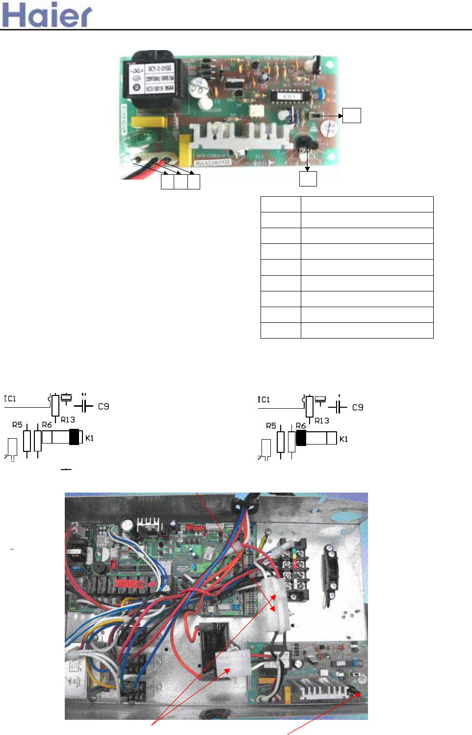
>a__WcU[S^<[c>a`V[e[a`Wc
Test K1 according to the following method:
50Hz is selected if dial K1 to the right
60Hz is selected if dial K1 to the lef
cut off the wiring clamp when use the fan speed adjusting board
Connect the two port
Dial P1 to realize fan speed adjusting
Fan speed adjusting board test method
Connect the test device with fan speed adjusting
board, dial power switch ON, then revolve P1 slowly to
place 1, place 2, place 3… until place 8, the indicate
lamp of port F(voltage output contolled by fan motor) will
change from dark to light, revolve P1 slowly from place 8
to place 1, the indicate lamp of port F will change from
light to dark.
Note: the voltage in each place is tested in the condition
of power voltage is 220V and frequence is 50Hz. When power characteristics (voltage, frequence)
change and load characteristic is different, the port F voltage output will change.
Place Port F voltage output˄VAC˅
1 132-139
2 151-158
3 168-175
4 184-190
5 196-203
6 205-211
7 212-218
8 220
P1
F
N
L
K1
Fan speed control board 001A3300352E
-155
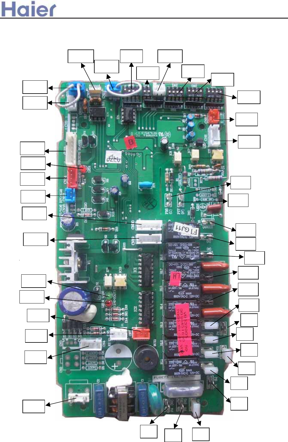
0010451690E
CN12
CN15
CN16
CN11
CN17
LED1
CN14
CN13
CN20
SW3
SW2
CN21SW5
SW4
CN19
CN7
LED4
LED5
CN5
CN4
P5
P7
P9
P6
P8
P10
P12
P11
P15
P14
P13
P17
CN1
P4 P3 P2
P1
P16
CN8
CN6
SW1
>a__WcU[S^<[c>a`V[e[a`Wc
-156-
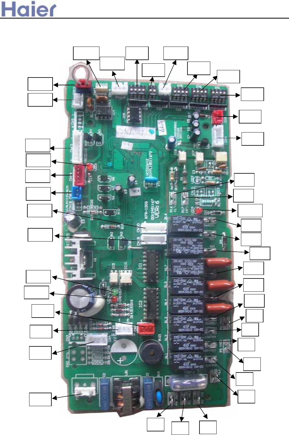
0010451167E
CN12
CN15
CN16
CN11
CN17
LED1
CN14
CN13
CN19
CN20
CN7
LED4
LED5
CN5
CN4
CN1
P4 P3 P2
P5
P7
P1
P9
P6
P8
P10
P12
P11
P15
P14
P13
P17
P16
LED3
CN8
CN6
SW1
SW3
SW2
CN21SW5
SW4
>a__WcU[S^<[c>a`V[e[a`Wc
-157-

>a__WcU[S^<[c>a`V[e[a`Wc
Condition for the PCB data:
1.Working ambient temperature:ˉ10ć̚70ć, relative humidity:30%̚95%
2.Preserved ambient temperature:ˉ20ć̚80ćˈrelative humidity˖30%̚95%
3.Power supply:220VACǃ50/60Hzˈvoltage range:160V̚250V
4.Precise of temperature control:r1ć
0010451167E PCB information – port and definition
P1üüconnect to external power supply, live line: L (220VAC)
P2üüconnect to external power supply, neutral line: N (0VAC)
P3ǃ4ǃ5ǃ6üücontrol external load, neutral line: N1ǃN2ǃN3ǃN4(0VAC)
P7üücontrol external load, electrical heat: HEAT (control output 220VAC)
P8üücontrol external load, health function: OXYGEN (control output 220VAC)
P9üücontrol external load, humidification: HUMI (control output 220VAC)
P10üücontrol external load, SWING(control output 220VAC)
P11üücontrol external load, WATER PUMP(control output 220VAC)
P12üücontrol external load, indoor fan motor low speed: L(control output 220VAC)
P13üücontrol external load, indoor fan motor mid speed: M(control output 220VAC)
P14üücontrol external load, indoor fan motor high speed: H(control output 220VAC)
P15üücommunication with fixed frequency single outdoor unit: COMM(0~220VAC)
P16üüinput control, signal live line: L’(220VAC)
P17üüinput control, signal neutral line: N’(0VAC)
CN1üüinput port of transformer (220VAC)
CN2üüinput port 1 of transformer (no use)
CN3üüinput port 2 of transformer (no use)
CN4üüinput port 3 of transformer (1-2ǃ14VACˈ3-4ǃ12VAC)
CN5üüinput control, connecting port to wired controller: CONTROLLER˄three bits: 1. power supply:
12VAC, 2. power supply: 0VAC, 3. communication: COMM.˅.
CN6üüinput control, ambient temp.-coil temp. sensor connecting port: ROOM/PIPE˄1-2ǃROOMˈ3-4ǃ
PIPEDŽ˅
Indoor ambient temp. sensor: R25=23K¡+-2.5%ˈB25/50=4200K+-3%ˈrange:˄-40ˈ80˅
Indoor coil temp. sensor: R25=10K¡+-3%ˈB25/50=3700K+-3%ˈrange:˄-20ˈ90˅
CN7üücontrol external load, fresh air control: FRESH˄1. blank, 2. power supply 0VDC, 3. control output:
12VDC.˅
CN8üüinput signal: FREEZE˄no use˅
CN9üüinput control˄no use˅
CN10üücommunication with fixed frequency single outdoor unit: (0~12VDC)
CN11üüinput signal, door switch: DOOR˄1-2 short circuit is normal, cut off P8 output˅
CN12üüinput signal, external alarm input: ALARM˄1-3 short circuit is normal, if cut off, air conditioner
stops work.˅
Note: For convertible type, cassette type, duct type units, CN11 and CN12 must be in short circuit, or
PCB will display failure information.
CN13üüinput signal, wiring port of remote receiver board: RECEIVE BOARD˄1. power supply 5VDC, 2.
power supply 0VDC, 3. remote signal, 4. signal output of running lamp 0VDC, 5. signal output of timer lamp
0VDC,6. signal output of power lamp 0VDC, 7. signal output of water pump running lamp 0VDC˅
CN14üücontrol external load, auto elevating function ˄1. signal of door switch close, 2. output of
elevating direction control 0VDC, 3. output of elevating power control 0VDC, 4. power supply 12VDC˅
-158-

>a__WcU[S^<[c>a`V[e[a`Wc
CN15üüinput signal, detecting water level of float switch ˄1-3 short circuit is normal, cut off shows that
level exceeds the limitation˅.If float switch cuts off or occurs other failure, LED1 will flash 10 times.
CN16üüinput control, wiring port of central controller: REMOTE˄1ǃRS485-Bˈ2ǃRS485-ADŽ˅
CN17üüoutput signal, output signal of failure alarm, control external load, 12V/ALM˄1. control output
0VDC, 2. power supply 12VDC˅
CN18üüoutput signal (no use)
CN19üücontrol external load, swing 1˄1ǃ16VDCˈ2ǃ0VDCˈ3ǃ0VDCˈ4ǃ0VDCˈ5ǃ0VDC.˅.
CN20 üücontrol external load, swing 2˄1ǃ16VDCˈ2ǃ0VDCˈ3ǃ0VDCˈ4ǃ0VDCˈ5ǃ0VDC.˅.
CN21üüinput signal, spring switch, CHECK˄1ǃinput signal of earthing, 2. power supply 0VDC˅
CN22üüshort circuit means selecting single split communication type.( no use)
CN23üüshort circuit means selecting multi split communication type.( no use)
0010451167E PCB information – function selection
˄
ON is 1, OFF is 0
˅
The standard condition for PCB in factory
SW1˖4 bits are OFF
SW2˖4 bits are OFF
SW3˖4 bits are ON
SW4˖2 bits are ON
SW5˖4 bits are ON
SW3-SW5: used for indoor unit to select different functions.(every dip switches are corresponding to J1-J10.
SW2-4üülogistic relationship of control function˄door card control and remote/ wired control˅0 means
logistic relationship is “and”, 1 means the later coming is preferential.
J1ˈSW3-1üüfunction selection-control type: 1 means remote control, 0 means wired control.
J2ˈSW3-2üüfunction selection-temperature compensation in heating mode: 1means “yes”, 0means “no”.
J3ˈSW3-3üüfunction selection-outdoor communication: 1means “yes”, 0means “no”. This PCB must be 1.
J4ˈSW3-4üüfunction selection-heat pump unit: 1means “heat pump”, 0means “cooling only”.
1/60üütest in short circuit, but in operation short circuit mustn’t be permitted.
CHECKüüshort spring switch control, it also can be used as switch of convertible type except for testing.
J5ˈSW4-1üüfunction selection-elevating function: 1means “yes”, 0 means “no”.
J6ˈSW4-2üüfunction selection –health function: 1means common (indoor fan motor running); 0 means
special (indoor, outdoor running).
J7ˈSW5-1üüfunction selection –swing mode: 1 means common˄simultaneous motor˅, 0 means special
(swing motor).
J8ˈSW5-2üüfunction selection – system combination: 1means fixed frequency single unit, 0 means fixed
frequency multi split.
J9ˈSW5-3üüfunction selection –group control: 1 stands for the master unit (its address in wired controller
is 0), 0 stands for the slave units (the address should be set by the dip switch, their addresses only can be in the
range: 1~15)
0010451167E PCB information- control type
Control type selection between remote and wired: select by dip switch J1, SW3-1˄1 means remote control˗
0 means wired control.)
For remote control type, please use remote controller YR-H71, and a remote receiver is equipped with
indoor unit. For wired control type, wired controller YR-E12 will be used, 3-core shied wire is equipped with
SW1-SW2: used for indoor unit to set unit address from 1 to 128’
J10ˈSW5-4üüfunction selection –preset.
-159-

>a__WcU[S^<[c>a`V[e[a`Wc
indoor unit.
Door card control: controls ON/OFF, the start up setting will comply with last time request memorized
according to condition memorize function. Its difference with emergency switch of convertible type unit lies: the
emergency switch control will perform in the condition: 24degrees, auto fan speed in auto mode.
The function combination between door card and remote/wired control type: select by dip switch: SW2-4˄0
means “and”, 1 means later coming is preferential.˅
Dip switch position in wired control type: Only one indoor unit of all indoor units connected with wired
controller is the master unit, whose address is 0, function selection switch˄J9ˈSW5-3˅is 1. The others are slave
units, and the quantity can be 0~15, whose addresses are˄SW1:1~4˅from 1 ~15, and cannot repeat.
Wiring request in wired control type: the wired controller ports A-B-C are connected with indoor port CN5
˄1-2-3˅ through 3-core shield wire. Requirements:
1. Port A only connects with either of indoor port CN5˄1˅
2. Port B connects with port CN5 (2) of all indoor units.
3. Port C connects with port CN5 (3) of all indoor units.
Dip switch position in central control type: the addresses ˄SW1:1~4˗SW2:1~4˅of indoor units connected
with central controller can not repeat. In principle, they should be in the order from small to big.
Wiring request in central control type: port A-B is connected with indoor port CN16˄A-B˅through 2-core
shield wire. Requirements:
1. Port A connects with port CN16˄A˅of all indoor units.
2. Port B connects with port CN16˄B˅of all indoor units.
When only use remote control type, please select remote control unit, and install according to installation
manual, there is no other special request.
When only use wired control type, please select wired control unit, and install according to installation
manual. When control multi indoor units, take care the requirements of dip switch and wiring, there is no other
special request.
When only use central control type, please firstly install according to air conditioner requests and set the
dipswitch, there is no other special request.
When central control type˄128h˅and remote control type are used simultaneously, set the dip switch
according to central control type, there is no other special request.
When central control type˄128h˅and wired control type ˄16h˅are used simultaneously, max. indoor units
sets: 128h16 can be controller. Address setting of central controller can be met firstly, and then modulate the
address setting of slave unit wired controlled.
LED in indoor PCB:
1. LED1˖is the state lamp for remote receiver as well as failure lamp. If indoor unit is normal, LED1 is on, or if
failure occurs, LED1 flashes regularly, and you can adjust failure type according to the flash times.
2. LED2˖is used for multi split units as communication lamp. If communication between indoor and outdoor is
normal, LED2 will be on.
3. LED3˖is used for single split units as communication lamp. If communication between indoor and outdoor is
normal, LED3 will be on.
4. LED4ǃLED5˖is the lamp that shows the data receiving or sending between wired controller and PCB, If
LED4ǃLED5 be on in turn, communication between wired controller and PCB is normal.
-160-
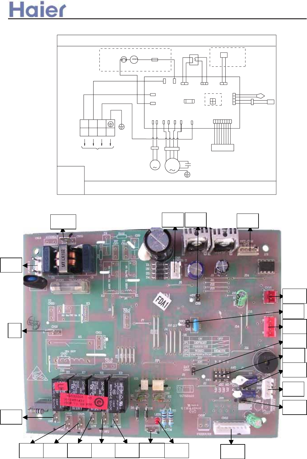
AP422ACEAA
>a__WcU[S^<[c>a`V[e[a`Wc
::+,7(%%/$&.
55('%/%/8(
<<(//(:
<*<(//(:*5((1
TO OUTDOOR UNIT
TERMINAL
BLOCK
127(
˖7+('(7(&725:+,&+,686('725($/,=(&(175$/&21752/,6237,21$/3$57
+($7(5,6127$9$/$%/()2512
(/(&75,&+($7,1*)81&7,2181,77+(6:,7&++$'%((16(77(',1)$&725<$1''2127&+$1*(
<*
%<%/5
5%:
<*
&1
&1 &1&1
&1&1&1&1
&1 &1 &1 &1
&1
&1
&1
&1
0
REMOTE
TRANS.
'(7(&725
ROOM TEMP.
PIPING TEMP.
FAN MOTOR
FAN MOTOR CAP.
MOTOR
SWING
5(680$%/(
3527(&725
+($7(5
21(2))3527(&725
0
FUSE
',36:,7&+
%0
T6.3A/250VAC
12
CIRCUIT DARGRMA OF INDOOR UNIT
CN19 CN6 CN8 CN9
CN16
CN17
CN2
CN10
SW3
CN14
CN3
CN15
CN12
CN21 LED1
CN22
CN23
CN24
CN25CN26
CN1
L
CN5
0010451432
-161-
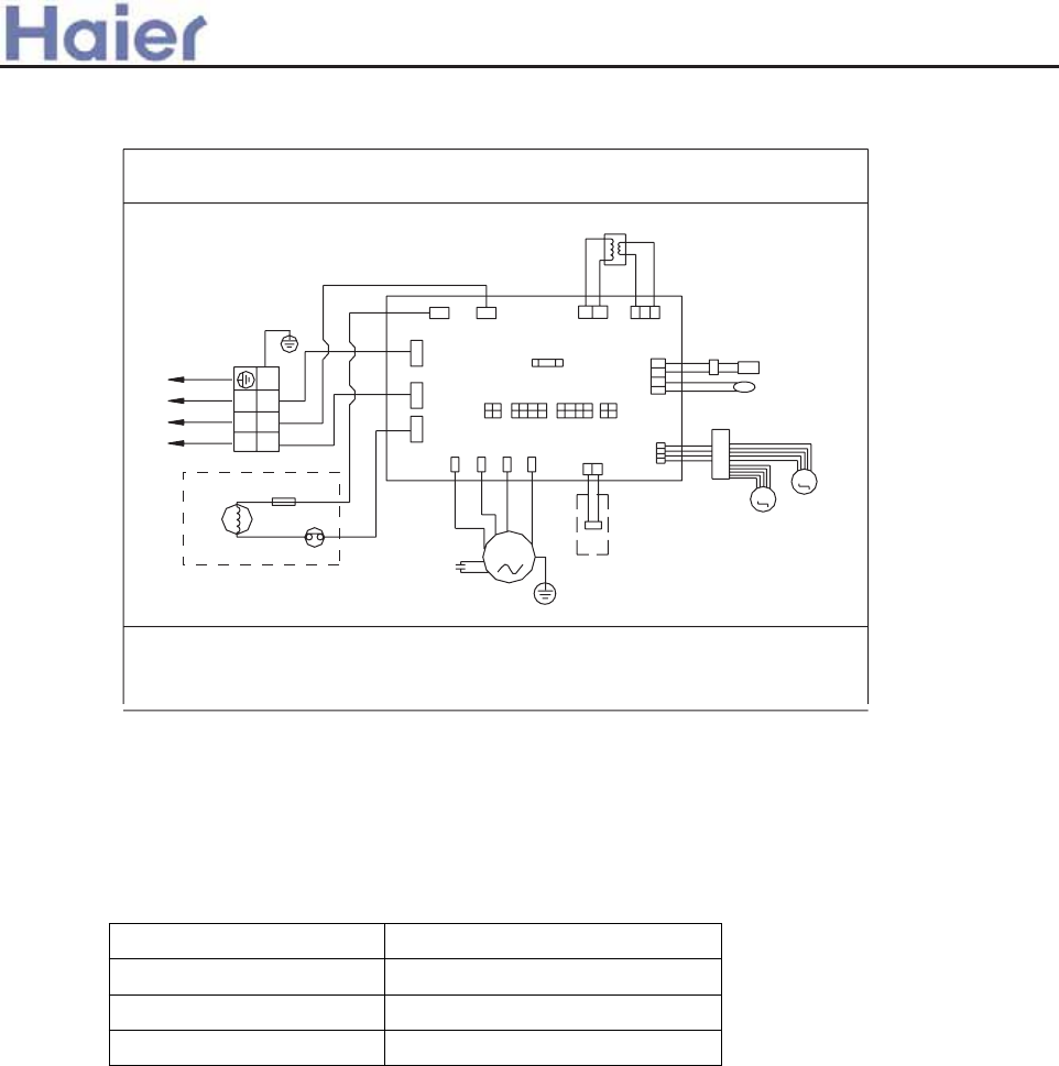
>a__WcU[S^<[c>a`V[e[a`Wc
B:BLACK
NOTE˖1ǃ
REMOTE CONTROLLER IS OPTIONAL .
2ǃREFER TO OPERATION INDOOR MANUL TO SET DIP BM1-BM4 .
PLEASE DO NOT CHANGE THE DIP SWITCH RANDOM.
3ǃNO ELECTRIC HEATING TYPE WITHOUT ELECTRIC HEATER.
R:RED
BL:BLUE
W:WHITE
Y/G:YELLOW/GREEN
2
13
CN13
CN12
CN11
CN22
CN2
SWING MOTOR
CONTROL PANEL
ROOM TEMP. SENSOR
PIPING TEMP. SENSOR
SWING
MOTOR
REMOTE CONTROLLER
Y/G
Y/G
FAN MOTOR
HEATER
TO OUTDOOR UNIT
W
ONE-OFF FUSE
RESUMABLE PROTECTOR
B
R
CAPACITOR
FUSE
M
M
BYBLR
T3.15A/250VAC
CN23
CN3
BM2
BM1
CN4CN24
CN25
CN10
BM4
BM3
CN7
CN5 CN6
TRANSFORMER
CIRCUIT DIAGRAM OF INDOOR UNIT
M
0010578100
AP482AKEAA
BM1 Funcion selection
BM1-1 ON/OFF cooling only / heat pump
BM1-2 ON/OFF Automatic run A / B mode
BM2 and BM3: used for indoor unit to set unit address from 1 to 128’
BM4 Panel selection Select the panel according to the 2 dip switch
Style of panel 1 2
Cabinet V panel OFF ON
Cabinet Z panel ON OFF
Wired controller ON ON
-162-
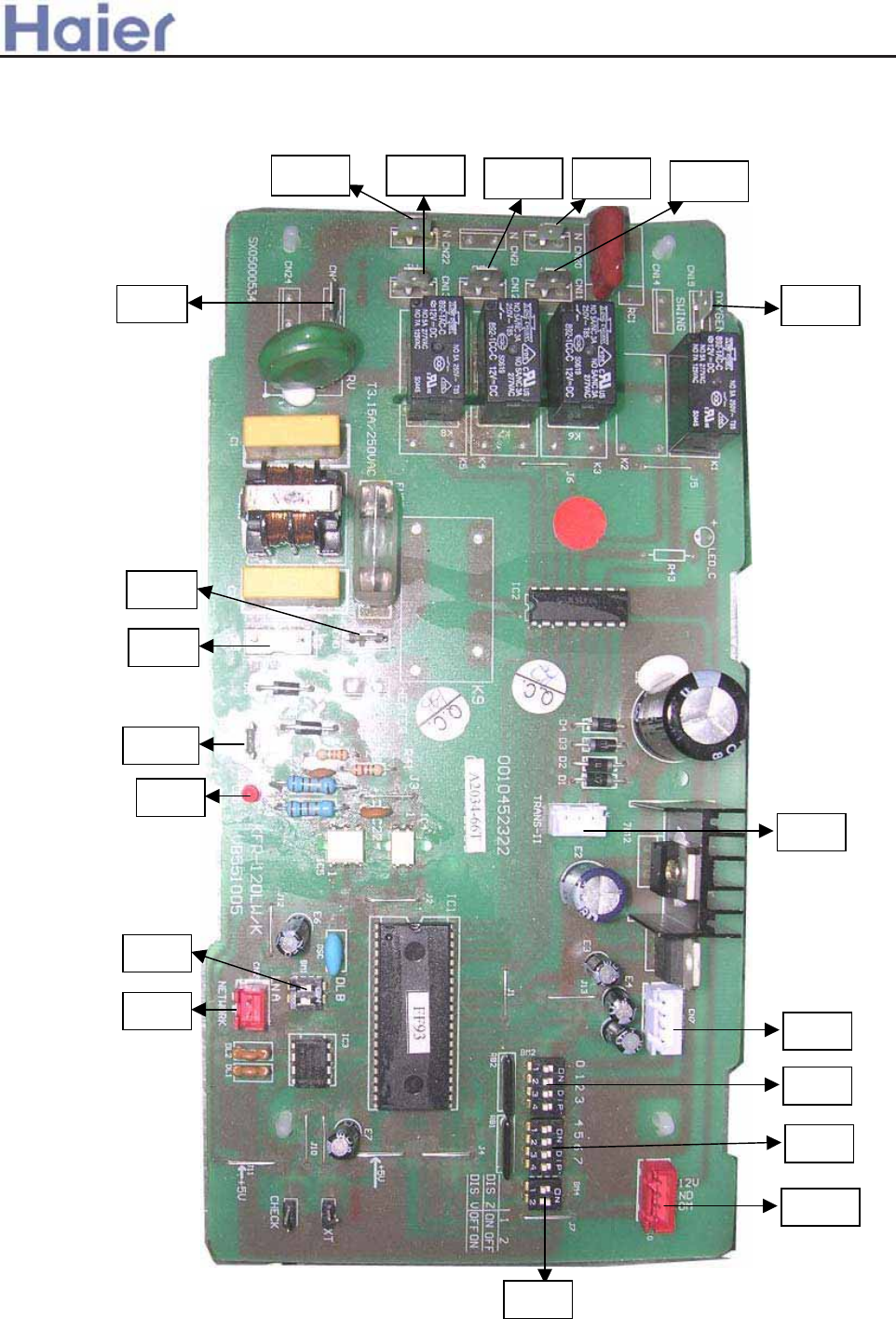
CN22 CN20
CN13 CN12 CN11
CN4 CN19
CN5
CN3
CN25
LED
CN2
BM1
CN7
BM4
CN10
BM3
BM2
CN6
>a__WcU[S^<[c>a`V[e[a`Wc
0010452322
-163-
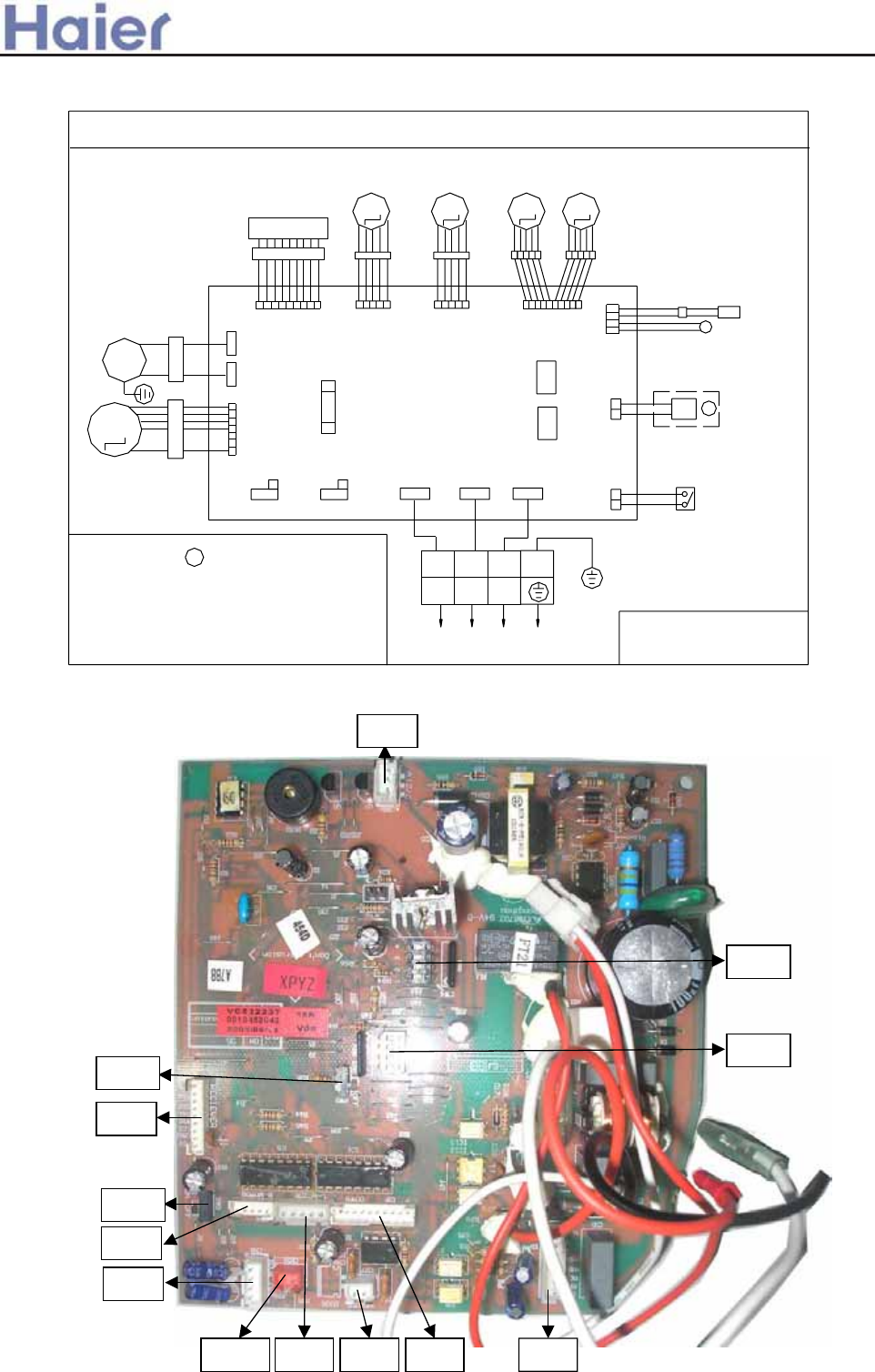
AS182AVERA
R-MOTOR
T3.15A/250VAC
FUSE
CN4
SWING
MOTOR 1
WIRING DIAGRAM OF WALL MOUNTED UNIT
0010576611
3.SW4-5: USED TO SET THE INDOOR UNIT NUMBER
WHEN IN GROUP CONTROL
1.DASHED PART IS OPTIONAL FOR
CENTRAL
CONTROL FUNCTION
DC FAN
MOTOR
2.SW2: USED TO SELECT MODEL ,SW3: USED TO
SELECT TEMP. COMPENSATE FUNCTION OF
HEATING MODE ,USER SHOULD NOT CHANGE THEM
NOTE:
ON
SW2
1
ON
SW3
OFF OFF
NEGATIVE ION
GENERATOR
M
Y/G
CN1
CON3
CN5
RECEIVER
M
CENTRALIZED
CONTROLLER
B:BLACK W:WHITE R:RED
Y/G:YELLOW/GREEN
TEMP.:TEMPERATURE
TO OUTDOOR UNIT
SIGNAL
LN
23(c)
1
BRW
CON2CON1
Y/G
SW1
CN10
EMERGENCY
SWITCH
SW4
SW5
UP DOWNL-MOTOR
CN3
1 2 3 4
ON
1 2 3 4
ON
CN7
CN2
CN6
SWING
MOTOR 3
M
SWING
MOTOR 2
M
M
SWING
MOTOR 4
PIPING TEMP.
SENSOR
ROOM TEMP.
SENSOR
1
>a__WcU[S^<[c>a`V[e[a`Wc
0010452042
CN5
CN4
CN6
CN10 CN3 CN7 CN2 CN1
CN8
SW4
SW5
SW2
SW3
-164-
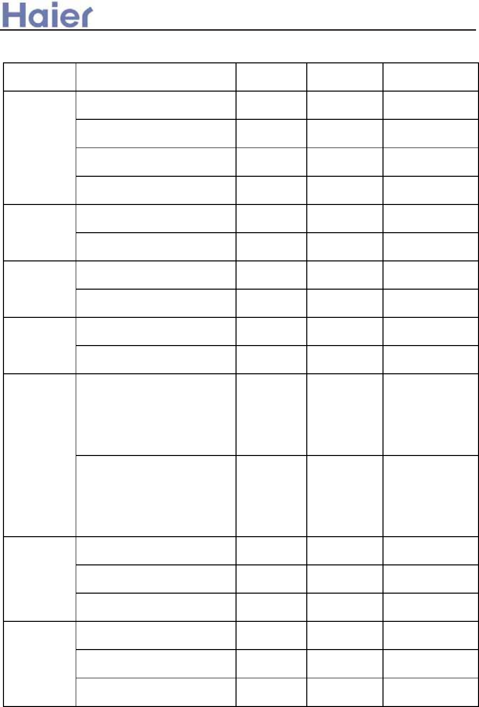
>a__WcU[S^<[c>a`V[e[a`Wc
8.4 sensor characteristic
model name code sub-part code characteristic
outdoor ambient temperature
sensor 0010450192 001A3800082 R25=10Kȍ±3%
B25/50=3700K±3%
mid-condenser temperature sensor 0010450195 001A3800093 R25=10Kȍ±3%
B25/50=3700K±3%
oil temperature sensor 0010451305 001A3800093 R25=10Kȍ±3%
B25/50=3700K±3%
discharging temperature sensor 0010451313 001A3800096 R80=50Kȍ±3%
B25/80=4450K±3%
ambient temperature sensor 001A3900159 001A3900003
R25=23Kȍ±2.5%
B25/50=4200K±3%
coil temperature sensor 001A3900006 001A3900004
R25=10Kȍ±3%
B25/50=3700K±3%
ambient temperature sensor 0010451323 001A3900003
R25=23Kȍ±2.5%
B25/50=4200K±3%
coil temperature sensor 001A3900006 001A3900004
R25=10Kȍ±3%
B25/50=3700K±3%
ambient temperature sensor 0010451323 001A3900003
R25=23Kȍ±2.5%
B25/50=4200K±3%
coil temperature sensor 001A3800128 001A3900004
R25=10Kȍ±3%
B25/50=3700K±3%
ambient temperature sensor 001A3900005 001A3900003 R25=23Kȍ±2.5%
B25/50=4200K±3%
coil temperature sensor 001A3900006 001A3900004 R25=10Kȍ±3%
B25/50=3700K±3%
outdoor ambient temperature
sensor 001A3900110 001A3800090 R25=5Kȍ±3%ˈ
B25/50=3450K±3%
coil temperature sensor 0010451312 001A3800091 R25=5Kȍ±3%ˈ
B25/50=3450K±3%
discharging temperature sensor 0010451313 001A3800096 R80=50Kȍ±3%
B25/80=4450K±3%
outdoor ambient temperature
sensor 001A3900110 001A3800090 R25=5Kȍ±3%
B25/50=3450K±3%
coil temperature sensor 0010451314 001A3800091 R25=5Kȍ±3%ˈ
B25/50=3450K±3%
discharging temperature sensor 0010450398 001A3800096 R80=50Kȍ±3%
B25/80=4450K±3%
AB182ACERA
AC242ACERA
AB182ACEAA
AC182ACEAA
AB242ACEAA
AD242ALEAA
AD242AMEAA
AD282AMEAA
AB362ACEAA
AC362AFEAA
AD362AMEAA
AD482AHEAA
AD602AHEAA
AU242AGERA
AB242ACERA
AB282ACEAA
AB482ACEAA
AB602ACEAA
AD242ALERA
AD182ALEAA
AC242ACEAA
AD242AMERA
AU242AGEAA
AU182AEEAA
-165-
>a__WcU[S^<[c>a`V[e[a`Wc
outdoor ambient temperature
sensor 001A3900110 001A3800090 R25=5Kȍ±3%
B25/50=3450K±3%
coil temperature sensor 0010451314 001A3800091 R25=5Kȍ±3%ˈ
B25/50=3450K±3%
discharging temperature sensor 0010450398 001A3800096 R80=50Kȍ±3%
B25/80=4450K±3%
ambient temperature sensor 001A3900005 001A3900003 R25=23Kȍ±2.5%
B25/50=4200K±3%
coil temperature sensor 001A3800128 001A3900004 R25=10Kȍ±3%
B25/50=3700K±3%
ambient temperature sensor 001A3900159 001A3900003 R25=23Kȍ±2.5%
B25/50=4200K±3%
coil temperature sensor 001A3800128 001A3900004 R25=10Kȍ±3%
B25/50=3700K±3%
coil temperature sensor 0010401922 001A3900004 R25=10Kȍ±3%
B25/50=3700K±3%
temperature sensor 001A3900159 001A3900003 R25=23Kȍ±2.5%
B25/50=4200K±3%
outdoor ambient temperature
sensor 0010450192 001A3800082 R25=10Kȍ±3%
B25/50=3700K±3%
mid-condenser temperature sensor 001A3800082 R25=10Kȍ±3%
B25/50=3700K±3%
oil temperature sensor 0010451305 001A3800093 R25=10Kȍ±3%
B25/50=3700K±3%
discharging temperature sensor 0010451313 001A3800096 R80=50Kȍ±3%
B25/80=4450K±3%
AC182ACERA
AD182AMERA
temperature sensor 001A3900005 001A3900003 R25=23Kȍ±2.5%
B25/50=4200K±3%
AS182AVERA coil temperature sensor 001A3900059
1.R25=10Kȍ±3%
B25/50=3700K±3%
2.R25=23Kȍ±2.5%
B25/50=4200K±3%
ambient temperature sensor 001A3800127 001A3900003 R25=23Kȍ±2.5%
B25/50=4200K±3%
coil temperature sensor 001A3900004 R25=10Kȍ±3%
B25/50=3700K±3%
ambient temperature sensor 001A3900005 001A3900003 R25=23Kȍ±2.5%
B25/50=4200K±3%
coil temperature sensor 001A3900006 001A3900004 R25=10Kȍ±3%
B25/50=3700K±3%
coil temperature sensor 001A3800128 001A3900004 R25=10Kȍ±3%
B25/50=3700K±3%
AP422ACEAA
AD282AHEAA
AC482AFEAA
AC602AFEAA
AD482AMEAA
AU182AFERA
AU48NAIEAA
AU60NAIEAA
AP482AKEAA
AU282AHEAA
AU36NAIEAA
AU362AIEAA
0010450195
0010401922
AD362AHEAA
-166-

>a__WcU[S^<[c>a`V[e[a`Wc
9. Failure code and troubleshooting
9.1 Failure code
For the inverter unit with new wired controller YR-E12 (0010451521E)
Number of
flashes of
remote
control and
indoor lights
Wire
control
readout
Centralize
d control
readout
Fault description Possible cause Remedy Purpose Items to be checked
10 08 21 Fault in drain system Float switch is disconnected
25min or longer.
Restorable when given
corrective signal.
To prevent condensate
spilling out of drain pan
Water line, water pump,
float switch, I/O voltage
1 01 01 Fault in indoor
ambient temperature
sensor
Sensor is open-circuit or
short-circuit for 2min or
longer.
Restorable when given
corrective signal.
To test input signal of
system.
Hardware connection, I/O
voltage division
2 02 02 Fault in indoor coil
temperature sensor
Sensor is open-circuit or
short-circuit for 2min or
longer.
Restorable when given
corrective signal.
To test input signal of
system.
Hardware connection, I/O
voltage division
3 4A 11 Fault in outdoor
ambient temperature
sensor
Sensor is open-circuit or
short-circuit for 2min or
longer.
Restorable when given
corrective signal.
To test input signal of
system.
Hardware connection, I/O
voltage division
4 49 12
Fault in outdoor coil
temperature sensor
Sensor is open-circuit or
short-circuit for 2min or
longer.
Restorable when given
corrective signal.
To test input signal of
system.
Hardware connection, I/O
voltage division
5 48 10
Overcurrent Detected CT current is
above the limit three times
within 30min.
Restorable after repair. To prevent overload
(electric parameter).
Power supply, wiring,
compressor, pressure
6 53 14
Fault with high
pressure
High pressure switch is
activated three times within
30min.
Restorable after repair. To prevent overload
(pressure parameter).
Wiring, circuit, pressure
switch, refrigeration
system
Power failure Wrong phase, phase failure
or phase loss.
Restorable after repair. To ensure power supply. Wiring, control board,
power supply
8 07 06 Communication error
between wire control
and indoor unit
Communication error lasts
4min or longer.
Restorable when given
corrective signal.
To ensure transmission to
and from control board.
Wiring, circuit,
transmission voltage
9 06 05 Communication error
between indoor and
outdoor units
Communication error lasts
4min or longer.
Restorable when given
corrective signal.
To ensure transmission to
and from control board.
Wiring, circuit,
transmission voltage
11 0B 30 External alarm signal
input
External signal is cut out for
10s or longer.
Restorable when given
corrective signal.
To control external
connection provided for
building.
External signal, wiring,
control board
12 03 20 Fault in outdoor
coil/suction line
sensor
Sensor is open-circuit or
short-circuit for 2min or
longer.
Restorable when given
corrective signal.
To test input signal of
system.
Hardware connection, I/O
voltage division
13 0D 31 Temperature shut-off Directional valve malfunction
repeats three times.
Restorable after repair. To prevent malfunction of
four-way valve.
Sensor, four-way valve,
system, control board
7 47 22
-167-

>a__WcU[S^<[c>a`V[e[a`Wc
14 4C 15 Fault in discharging
temperature sensor
Sensor is open-circuit or
short-circuit for 2min or
longer.
Restorable when given
corrective signal.
To test input signal of
system.
Hardware connection, I/O
voltage division
15 05 17 EEPROM error EEPROM data loss Default operation/reset
restoration.
To set data/control
parameter.
EEPROM, data match,
control board
16 54 26 Fault with low
pressure
Low pressure switch is
activated.
Restorable after repair. To prevent refrigerant leak. Wiring, circuit, pressure
switch, refrigeration
system
17 50 15 Detected temperature of
discharge line is higher than
120°C.
Restorable when lower
than 100°C.
To prevent overload
(temperature parameter).
Temperature, fan motor,
pressure, system
18 12 23 Fault in operation
mode
Indoor units operate in
different modes.
Restorable in same
operation mode.
To ensure same operation
mode.
User setting
19 4B Outdoor coil B Sensor is open-circuit or
short-circuit for 2min or
longer.
Restorable when given
corrective signal.
To test input signal of
system.
Hardware connection, I/O
voltage division
20 4D 15 Outdoor discharging
B
Sensor is open-circuit or
short-circuit for 2min or
longer.
Restorable when given
corrective signal.
To test input signal of
system.
Hardware connection, I/O
voltage division
21 20 07 Module error Module overheat,
overcurrent, lack of current,
short-circuit.
Restorable when given
corrective signal.
To prevent overload
(ultimate state).
Power supply, feedback,
compressor, control board
Overcurrent Detected CT current is
above the limit three times
within 30min.
Restorable after repair. To prevent overload
(electric parameter).
Power supply, wiring,
compressor, pressure
5 48 10
Power failure Wrong phase, phase failure
or phase loss.
Restorable after repair. To ensure power supply. Wiring, control board, power
supply
Fault in outdoor coil
temperature sensor
Sensor is open-circuit or
short-circuit for 2min or
longer.
Restorable when given
corrective signal.
To test input signal of
system.
Hardware connection, I/O
voltage division
4 49 12
Fault in discharging
temperature sensor
Sensor is open-circuit or
short-circuit for 2min or
longer.
Restorable when given
corrective signal.
To test input signal of
system.
Hardware connection, I/O
voltage division
Fault with high
pressure
High pressure switch is
activated three times within
30min.
Restorable after repair. To prevent overload
(pressure parameter).
Wiring, circuit, pressure
switch, refrigeration system
6 53 14
Fault with low
pressure
Low pressure switch is
activated.
Restorable after repair. To prevent refrigerant
leak.
Wiring, circuit, pressure
switch, refrigeration system
The others are the same as inverter unit.
Compressor overheat
0C
Note: As for the fixed frequency units, remote control and indoor lights flash times 12 and 21(Module error) is not available. While 7 (Power failure) 14
(fault in discharging temperature sensor) and 16 (Fault with low pressure) is shown as following:
-168-
Short-circuit -ON-ĜOpen-circuit -OFF-hFunction description Note
Bit0 Address code Ā1āAddress code “0āCentral control indoor address Bit0/wired control indoor address Bit0
Bit1 Address code Ā1ā Address code Ā0āCentral control indoor address Bit1/wired control indoor address Bit1
Bit2 Address code Ā1ā Address code Ā0āCentral control indoor address Bit2/wired control indoor address Bit2
SW1-1
2
3
4Bit3 Address code Ā1ā Address code Ā0āCentral control indoor address Bit3/wired control indoor address Bit3
Bit4 Address code Ā1ā Address code Ā0āCentral control indoor address Bit4
Bit5 Address code Ā1ā Address code Ā0āCentral control indoor address Bit5
Bit6 Address code Ā1ā Address code Ā0āCentral control indoor address Bit6
SW2-1
2
3
4SLCT Control combination: AND Control combination: the later
entering in priority
Control mode: remotr or wired control and passive port control
J1 Control type: remote control Control type: wired control Select control type, communication port and protocol selection
J2 Heating temp. compensation 4ć Heating temp. compensation 0ćSelect temp. compensation
J3 Control type: with outdoor PCB Control type: without outdoor PCB Select control type, control board
SW3-1
2
3
4J4 Heat pump type Colling only type
1/60 1/60 In time shorting state Normal state
CHECK CHECK Use compulsory switch Normal state
J5 Ornarment or not h/Ĝ
SW4-1
2J6 Oxygen or not h/Ĝ
J7 Other/2P convertible type Ĝ/h
J8 Single split/multi split Ĝ/h
J9 Indoor address 0 Setting indoor address by SW1 Select the address of wired control type multi indoor unit
SW5-1
2
3
4J10 Fixed frequency Inverter
Central control indoor address: the indoor unit should be connected by the different uniquely address when select central control type, or will influence the control. For example, if
the address repeat, the control information will conflict or communication system will breakdowm. Central control address = dip switch value+1.
Wired control indoor address: the indoor unit should be connected by the different uniquely address when select wired control type, or will influence the control. For example, if
J9=ON, the wired controller can only indicate 1 indoor unit no matter how many indoor units its connected. Wired control address = dip switch value.
>a__WcU[S^<[c>a`V[e[a`Wc
Functions and notes for dip switch (Ĝ shows ON, h shows OFF ) (for 0010451690E)
-169-
Failure code for wall mounted unit(AS182AVERA) ---- displayed on the indoor LCD:
Failure
code
description Remark
E1 Indoor room temperature sensor failure Indoor room temp. sensor in short circuit, or open
circuit, it can resume due to the signal.
E2 Indoor coil temperature sensor failure Indoor coil temp. sensor in short circuit, or open
circuit, it can resume due to the signal.
E4 EEPROM wrong Being electrified to test E2 check sum, or E2 is
broken down.
E7 Communication failure between indoor and
outdoor
Communication failure alarms for 4 minutes
contineously, it can resume due to the signal.
E14 Indoor fan motor failure Indoor fan motor wrong wiring or indoor fan motor
abnormal.
E18 Temperature cutoff protection Outdoor 4-way valve response abnormal.
F1 Module failure Outdoor module abnormal
F2 Outdoor DC motor failure Outdoor DC motor abnormal
F4 Compressor overheat / discharging
temperature protection
Compressor discharging temperature over high
protection
F5 Module over current / current transducer
failure
F6 Outdoor ambient temp. sensor abnormal Outdoor ambient temp. sensor in short current or
open circuit
F7 Outdoor suction/defrosting temp. sensor
abnormal
Outdoor suction/defrosting temp. sensor in short
circuit or open circuit
F8 High pressure abnormal High pressure too high
F9 Low pressure abnormal Low pressure abnormal
F10 No AC power supply
F11 Outdoor PCB EEPROM abnormal Being electrified to test if the E2 check sum is
correct or failure
F13 Communication failure between outdoor
PCB and module
F14 Compressor discharging temp. sensor
failure
Outdoor compressor discharging temp. sensor in
short circuit or open circuit
F15 Compressor running faulty Resumable
F16 Running state-detecting circuit failure Outdoor DC compressor running state-detecting
circuit failure, or compressor abnormal, resumable
>a__WcU[S^<[c>a`V[e[a`Wc
Failure code for AP482AKEAA
No. Fault description Operation panel display
1Indoor ambient temp. sensor failure E1
2 Indoor coil temp. sensor failure E2
3 Outdoor ambient temp. sensor failure E3
4Outdoor coil temp. sensor failure E4
5 CT current failure E5
6 Pressure protection E6
7E8
8 Communication failure between indoor and outdoor PCB E9
Communication failure between indoor units and panel
-170-
Failure code for fix frequency outdoor unit unit(AU*EAA):
Diagnostic code for the inverter outdoor unit
>a__WcU[S^<[c>a`V[e[a`Wc
Code on wired
controller
Flash times of indoor
receiver board
Room temp. sensor abnormal 01 Power LED flashes 1 time
Indoor coil temp. sensor abnormal 02 Power LED flashes 2 times
Outdoor temp. sensor abnormal 4A Power LED flashes 3 times
Outdoor coil temp. sensor abnormal 49 Power LED flashes 4 times
48 Power LED flashes 5 times
High / Low pressure abnormal 53 Power LED flashes 6 times
Communication malfunction between indoor and wired
controller 07 Power LED flashes 8 times
Communication malfunction between indoor and outdoor
abnormal 06 Power LED flashes 9 times
Drainage system malfunction 08 Power LED flashes 10 times
Alarm of exterior annunciator 0B Power LED flashes 11 times
Coil gas pipe temp. Sensor abnormal 03 Power LED flashes 12 times
Temperature protection malfunction 0D Power LED flashes 13 times
Please refers to PCB function part, page 133 and page 134.
Central
-ized
control
readout
Panel
Fault description Possible cause Remedy
1 01D E1 Fault in indoor ambient
temperature sensor
Sensor is open-circuit or
short-circuit for 2min or longer.
Restorable when given
corrective signal.
2 02D E2 Fault in indoor coil
temperature sensor
Sensor is open-circuit or
short-circuit for 2min or longer.
Restorable when given
corrective signal.
3 11D E3 Fault in outdoor ambient
temperature sensor
Sensor is open-circuit or
short-circuit for 2min or longer.
Restorable when given
corrective signal.
4 12D E4 Fault in outdoor coil
temperature sensor
Sensor is open-circuit or
short-circuit for 2min or longer.
Restorable when given
corrective signal.
5 10D E5 Overcurrent/ Power
failure
Detected CT current is above the
limit three times within 30min.
Restorable after repair.
6 14D E6 Fault with high pressure High pressure switch is activated
three times within 30min.
Restorable after repair.
9 05D E9 Communication error
between indoor and
outdoor units
Communication error lasts 4min
or longer.
Restorable when given
corrective signal.
14 15D Fault in discharging
temperature sensor
Restorable when given
corrective signal.
6 26D E6 Fault with low pressure Low pressure switch is activated
over 30s.
Restorable after repair.
Failure code for AP422ACEAA
display
Number
flashes
of
E4 Sensor is open-circuit or
short-circuit for 2min or longer.
Failure description
Over-current malfunction/Power failure
-171-
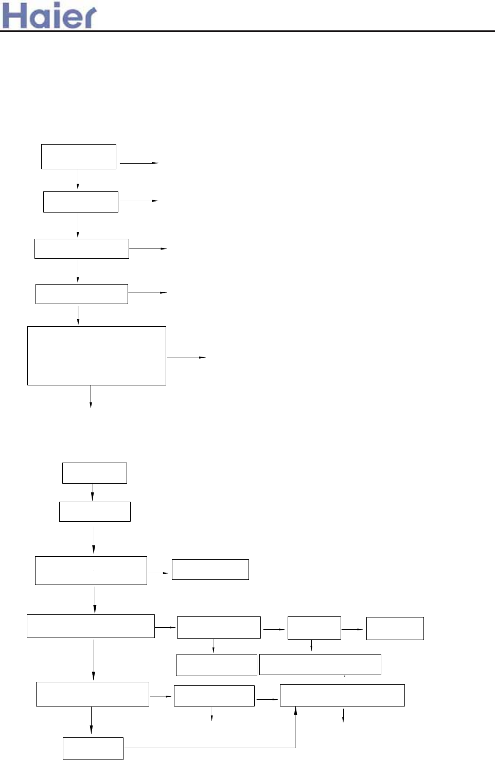
>a__WcU[S^<[c>a`V[e[a`Wc
9.2 Troubleshooting for inverter units
Outdoor troubleshooting:
Re
p
lace sensor
yes
Replace PCB
no
Below the indication on indicator board sequence
is LED5-LED4-LED3-LED2-LED1, 0: OFF; 1: ON
1) Sensor failure
no
no
no
yes
yes
yes
For sensor failure of ambient,
suction and coil temperature,
check if resistor R31/R32/R33
value of outdoor PCB is 20K; for
discharging temperature sensor
failure, check if R46 is 47K
Replace sensor
Is sensor resistance
acceptable? Replace sensor
Is sensor short-circuit
or open-circuit?
check if the wiring is
correct according to
wiring diagram
no reconnect
Relocate
if sensor is fixed
well
Alarm condition: ambient temperature sensor is in short
circuit or open circuit for 3 seconds continously.
Outdoor indicator displays 00110 or 00111, or 01001
replace compressor
no
wiring correctly
no
compressor can
not start up
no
if compressor winding is normal, and
the each phase resistor is in balance
yes
if compressor wiring is
correct
yes
stop the unit, restart up until power
module temperature has reduced
no
no
improve the ventilation
condition
if the refrigerant
is normal
yes
if the total load
is too big
yes
yes
2) Outdoor power module failure
compressor startup procedure is
abnormal, and vibrates seriously
yes
if ventilation beside the
module radiator is good
check if module bottom temperature
is over high, more than 90degree
no
yes
yes check if the system is
blocked
check if the any current among
compressor input port U-V-W is
over high
outdoor indicator
displays 00001
Alarm condition: outdoor indicator displays 10111, 00001, or 01111, 10000, 100001,
or 10100
Re-electrified after
being powered off
-172-
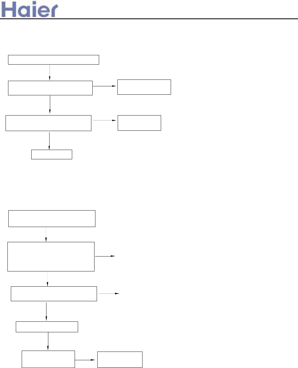
>a__WcU[S^<[c>a`V[e[a`Wc
Warning: For outdoor DC fan motor, forbidden to pull off the plug when
being electrified.
Replace motor
Check if the outdoor unit fan
blade is blocked by some objects
Check if the lead wire of DC motor
is broken or short-connected
no
yes
adjust lead wire
of fan motor
adjust fan blade to
make it run normally
3) Outdoor DC motor abnormal
outdoor indicator shows 00010
Outdoor indicator displays 00010.
Alarm condition:outdoor DC motor is blocked rotor or broken, abnormal.
This fault is only used when indoor unit is with DC fan motor.
yes
no
For wall mounted unit:
yes
check if the failure
is eliminated
yes
no
4) Communication error between indoor and outdoor units
Outdoor indicator shows 00011
LCD of wall mounted displays
E7
yes
If communication wire is
damaged or broken off
Check if communication wiring
between indoor and outdoor is
correct and if power wiring is
correct
Replace indoor PCB
no adjust wiring
re-wiring
Replace outdoor
PCB
no
-173-
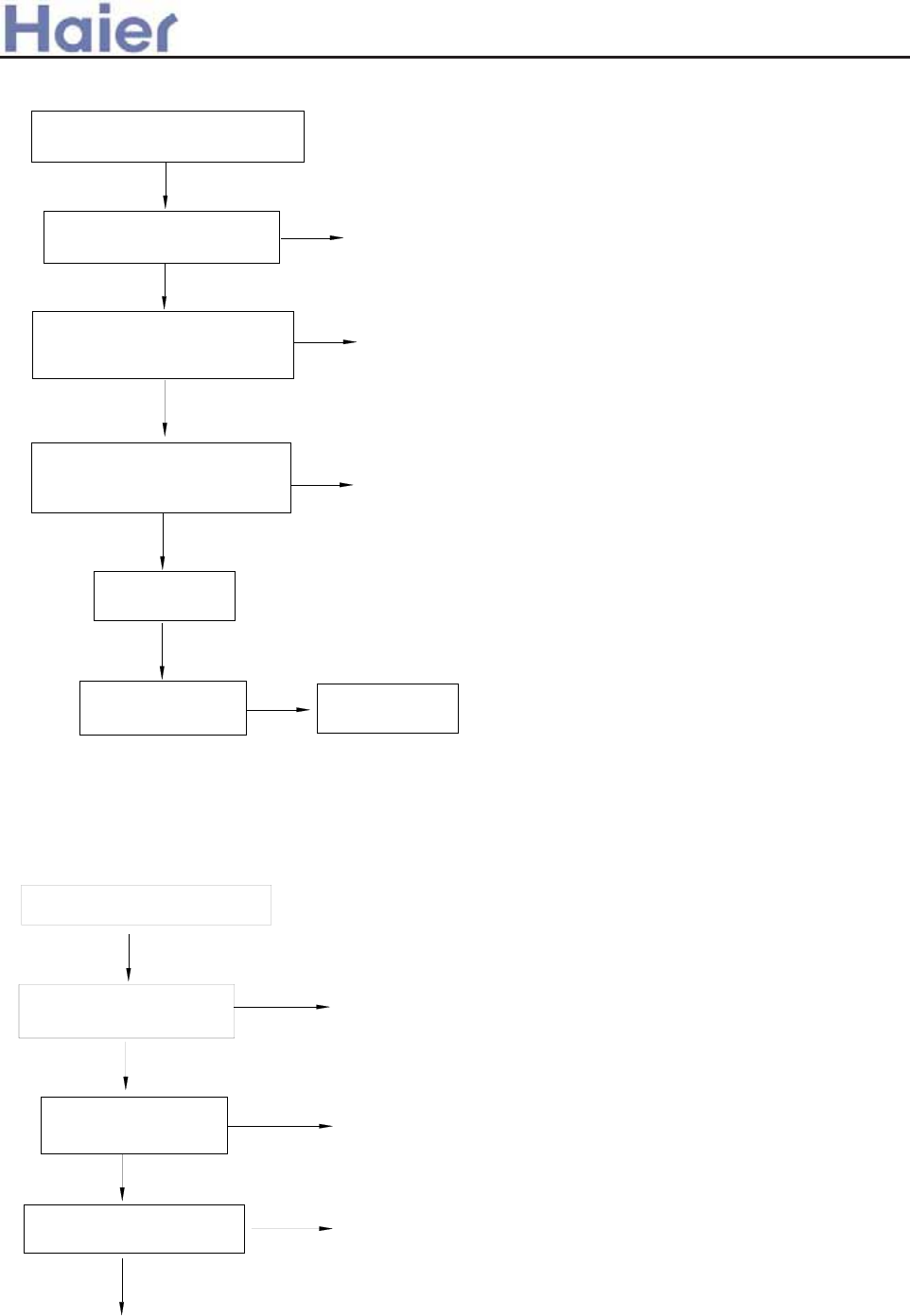
Replace indoor
PCB
yes
adjust the
position
no
no Replace outdoor
PCB
adjust wiring and
power supply
eliminate other
faults
yes
check the 4th bit of SW5 on
PCB is at "OFF", the others
are at "ON"
if indoor unit alarms other
failure codes
check if wiring between indoor
and outdoor is correct, power
supply is 50Hz
no
compressor can not startup after
unit is switched on for 4 minutes
yes
check if the failure
is eliminated
yes
For convertible unit and ceiling concealed unit:
re
p
lace PCB
yes
replace sensor
no
no
adjust piping
outdoor indicator shows
yes
adjust refrigerant
check if the system
piping is blocked
check if refrigerant is too
much or too less
check if discharging temp.
sensor value is normal
no
yes
5)Compressor discharging temperature protection
Outdoor indicator shows 00100.
Alarm condition: Within half an hour after compressor is running, compressor
discharging temperature is over 120degree for 3 times continously.
>a__WcU[S^<[c>a`V[e[a`Wc
-174-
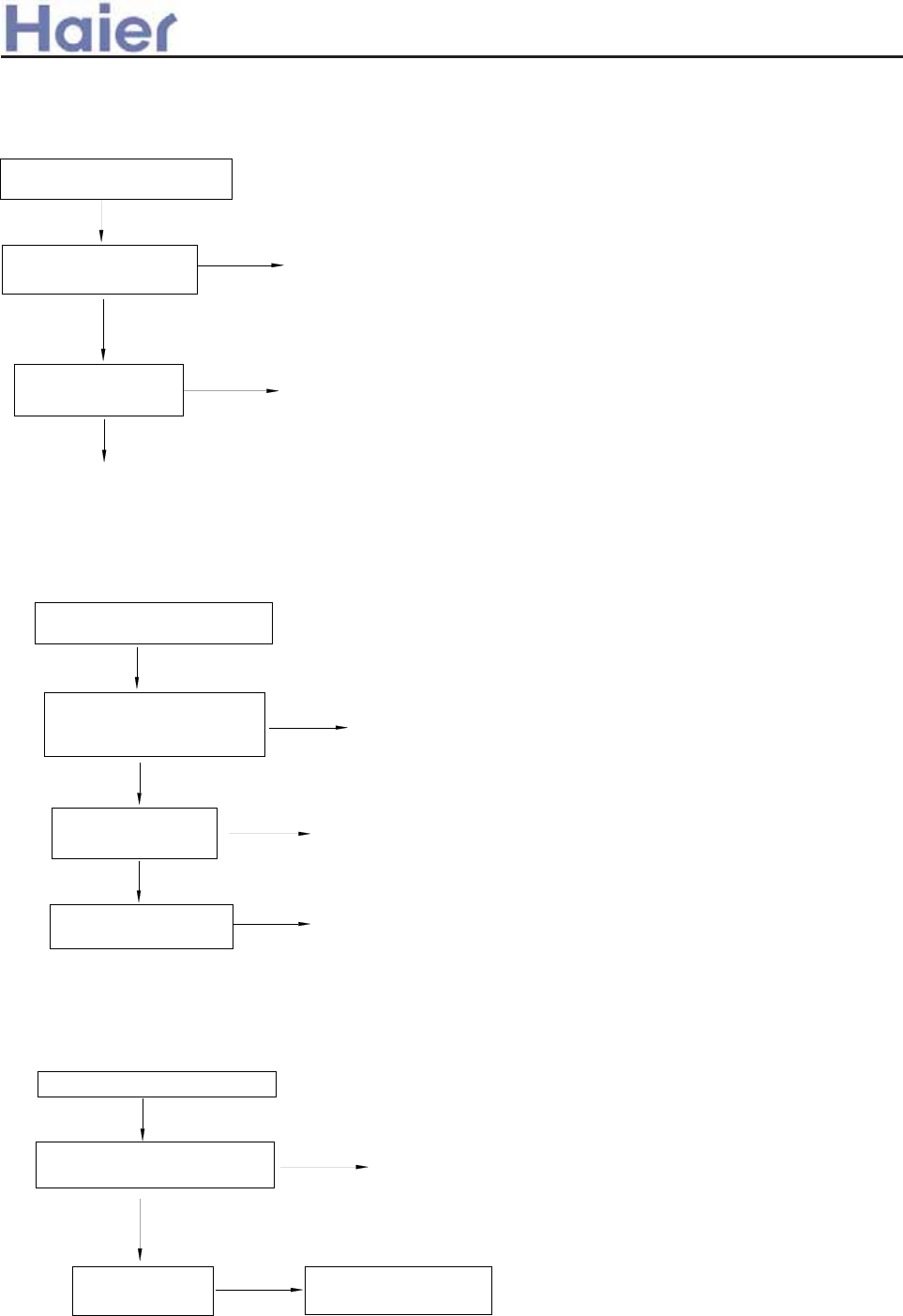
adjust piping
Outdoor indicator shows 00101.
Alarm condition: When compressor running, the module current is over 21A.
6) Outdoor SPDU module over current protection
replace SPDU
module
adjust refrigerant
yes
no
yes
no
outdoor failure indicator shows
00101
check if the refrigerant is
too much or too less
check if the piping is
blocked
replace sensor
yes
adjust piping
adjust refrigerant
yes
check if the piping is
blocked
Outdoor indicator shows 01000
Alarm condition: When compressor running, high pressure is over 4.5 MPa for 30
seconds continously.
7) Outdoor high pressure protection
outdoor failure indicator shows
01000
yes
no
no
check if the refrigerant is too
much or less by the pressure
gauge
if high pressure switch
is normal
adjust wiring
Outdoor indicator shows 01010
Alarm condition: if power supply is not 50Hz as standard, which will affect the
normal communication and cause air conditioner bad operation.
8) Outdoor power supply is abnormal
adjust power supply as
50HZˈ220-230VAC
no
yes
check if power
supply is normal
outdoor indicator shows 01010
no
check if the wiring between
indoor and outdoor is correct
>a__WcU[S^<[c>a`V[e[a`Wc
-175-
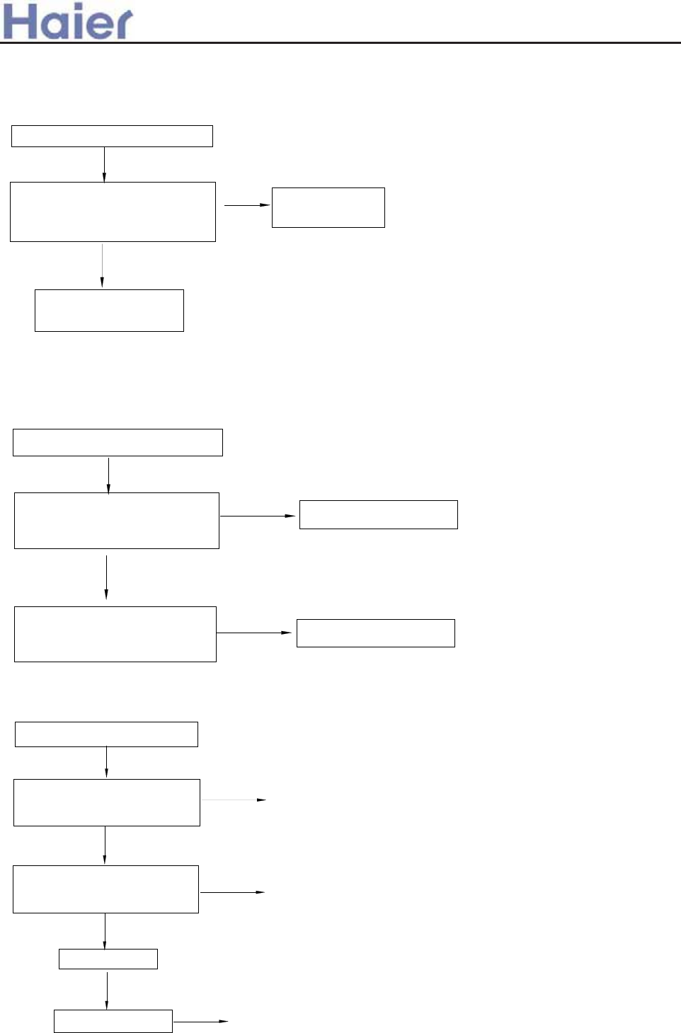
Outdoor indicator shows 01110.
Alarm condition: EEPROM is fault or data is missing.
9) EEPROM is abnormal
adjust EEPROM
welded point
no
yes
outdoor indicator shows 01110
check if EEPROM welded points
on outdoor PCB is in good
condition
EEPROM data is
missing, replace PCB
replace compressor
Outdoor indicator shows 10011.
Alarm condition: when compressor is running, the unit will be abnormal or stop.
10) Running state detecting abnormal
no
eliminate other troubles
no
yes
when compressor starting up,
unit stops abnormally and
can not start up normally
Re-electrified after power off,
check if compressor can start
up normally
outdoor indicator shows 10011
replace module
adjust wiring
Outdoor indicator shows 10110
11) Communication failure between outdoor PCB and module
no
if problem is solved
yes
replace PCB
eliminate other failures
no
no
yes
outdoor indicator shows 10110
compressor not start up, outdoor
alarms, check if there is other
failure
check if the wiring between
outdoor PCB and module is
correct
>a__WcU[S^<[c>a`V[e[a`Wc
-176-
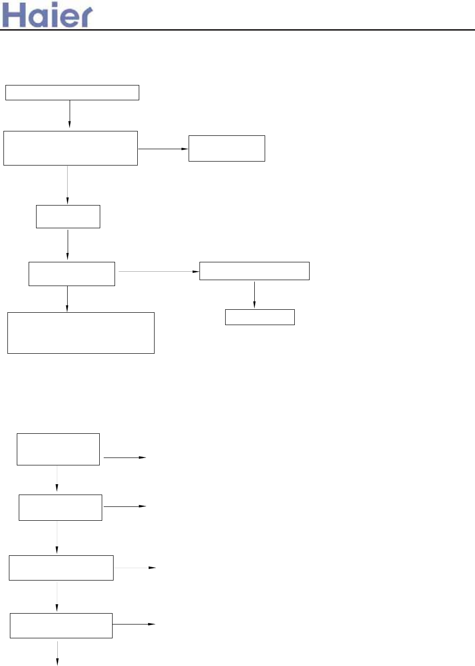
Indoor troubleshooting:
no
Outdoor indicator shows 11000.
Alarm condition: outdoor system pressure is lower than 0.05MPa.
12) Outdoor low pressure abnormal
outdoor indicator shows 11000
yes
no
low pressure
abnormal
replace pressure
switch
yes
dredge piping
check if piping is blocked
yes
check if high
pressure is low,too
Lack of refrigerant, charge
additional refrigerant and check if
piping leaks, if yes, replace piping
measure actual pressure by a
pressure gauge to adjust the
output failure
Alarm condition: ambient temperature sensor is in short
circuit or open circuit for 2 seconds continously.
if sensor is fixed
well Relocate
reconnect
no
check if the wiring is
correct according to
wiring diagram
Is sensor short-circuit
or open-circuit?
Replace sensor
Is sensor resistance
acceptable?
Replace sensor
Replace PCB
yes
yes
yes
no
no
no
1) Sensor failure
>a__WcU[S^<[c>a`V[e[a`Wc
-177-
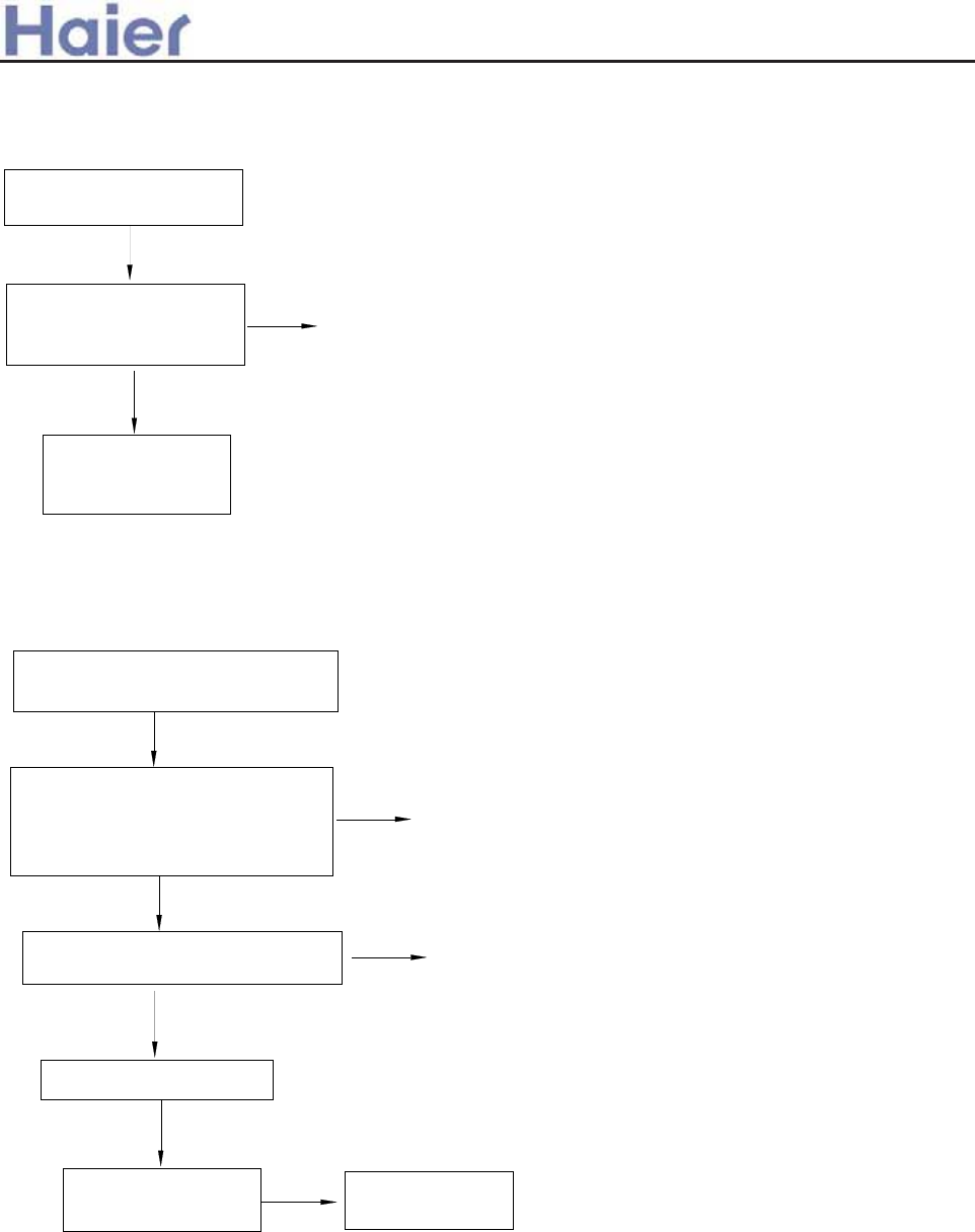
Alarm condition: before being electrified, EEPROM
is faulty or the data is missing.
The indication on indicator board sequence is
LED5-LED4-LED3-LED2-LED1, 0: OFF; 1: ON
2) EEPROM failure
outdoor failure indicator
shows 01110
modify the
welded point
yes
check the EEPROM
welded point on outdoor
PCB is normal
EEPROM data is
missing, replace
PCB
no
no Replace outdoor
PCB
re-wiring
no
Replace indoor PCB
Check if communication wiring
between indoor and outdoor is
correct and if power wiring is
correct
If communication wire is
damaged or broken off
yes
LCD of wall mounted displays
E7
no
yes
check if the failure
is eliminated
yes
3
) Communication error between indoor and outdoor units
>a__WcU[S^<[c>a`V[e[a`Wc
-178-
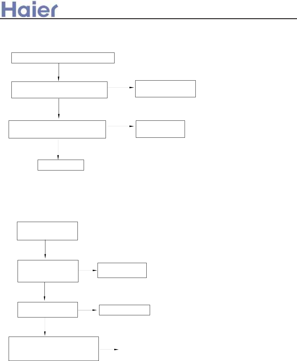
no
yes
Alarm condition:outdoor DC motor is blocked rotor or broken, abnormal.
This fault is only used when indoor unit is with DC fan motor.
LCD of wall mounted unit display F2
4) Indoor DC motor abnormal
adjust fan blade to
make it run normally
adjust lead wire
of fan motor
yes
no
Check if the lead wire of DC motor
is broken or short-connected
Check if the indoor unit fan blade
is blocked by some objects
Replace motor
Warning: For outdoor DC fan motor, forbidden to pull off the plug when
being electrified.
Alarm condition: indoor coil temperature sensor value is abnormal;
or outdoor 4-way valve coil is invalid
Check if indoor coil
temp. sensor value is
normal
Replace coil
temp. sensor
LCD on wall mounted
unit displays E18
Check if resistor R34
on PCB is 20K replace resistor
When only powering to outdoor
4-way valve coil, check if the coil
can reverse normally
replace 4-way valve
no
yes
no
yes
no
>a__WcU[S^<[c>a`V[e[a`Wc
5) Temperature cutoff protection
-179-
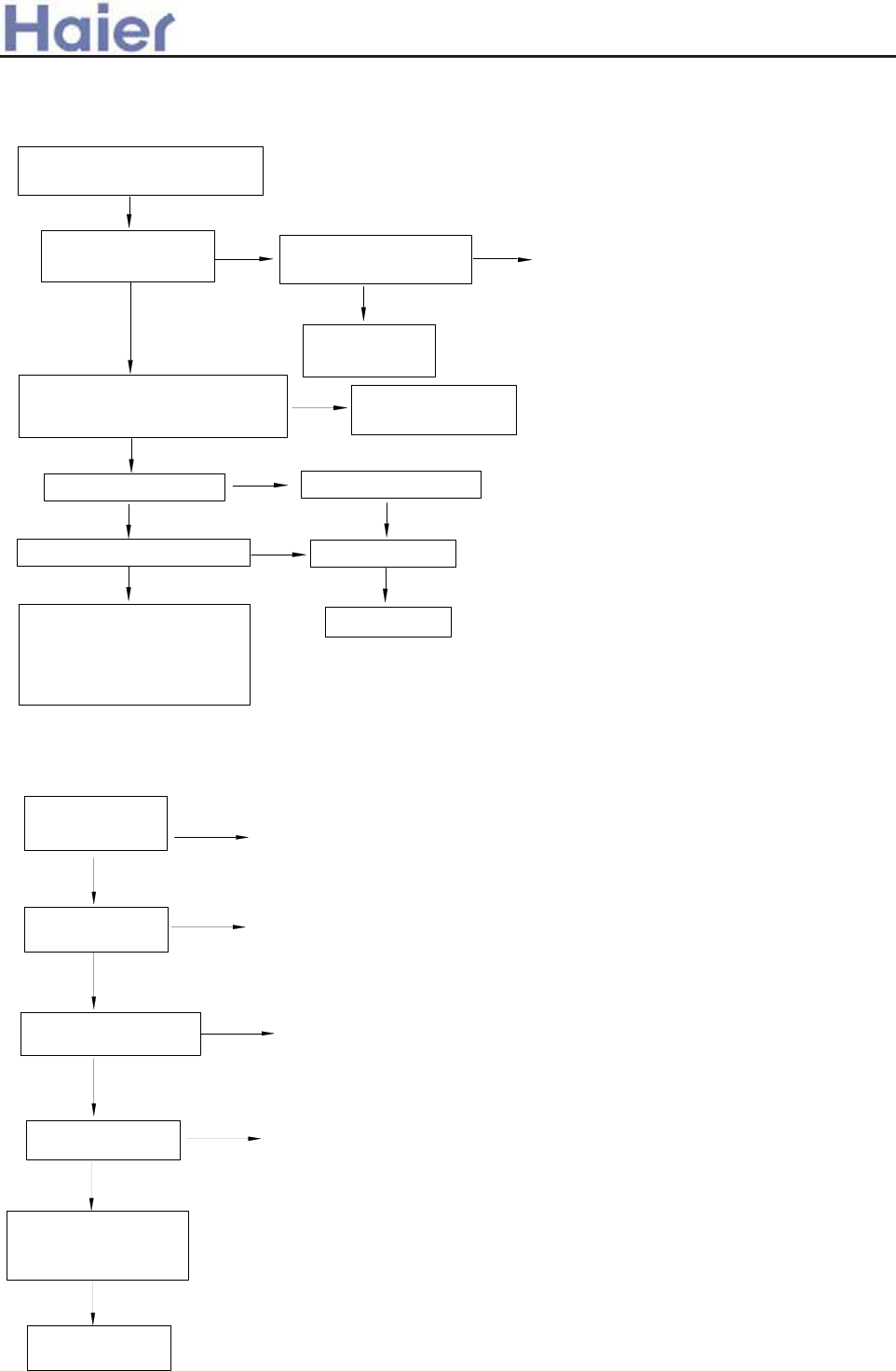
Is actual pressure detected by
pressure gage acceptable?
yes
no
low pressure failure no high pressure failure
yes
yes
Is high pressure too low? no is pipe blocked?
yes
Refrigerant charge is
needed. Check if there is
refrigerant leak. If yes,
replace pipe.
yes
dredge piping
Change pressure
switch
no
Make them in
short circuit
Note: The confirmation time of low pressure failure may be shorter, but high pressure failure confirmation
time is at least 1 hour. Besides, take the ambient temperature into consideration.
1) Pressure protection
Confirm the fault according
to the fault code list
Does system have
pressure switch? Are CN17 and CN18
in PCB cut off?
no
Replace PCB
yes
yes
no
no
no
yes
yes
yes
yes
Replace PCB
Is DC voltage between
both ends of sensor
near 5V or 0V?
Replace sensor
Is sensor resistance
acceptable?
Replace senso
r
Is sensor short-circuit
or open-circuit?
check if the wiring is
correct according to
wiring diagram
2) Sensor failure
no reconnect
Relocate
if sensor is fixed
well
9.3 Troubleshooting for fixed frequency units
Re
>a__WcU[S^<[c>a`V[e[a`Wc
-180-
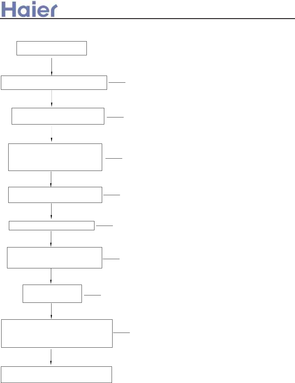
>a__WcU[S^<[c>a`V[e[a`Wc
Confirm the fault according
to the fault code list
Are connectors of pressure switch in good
condition?
no Check and reconnect
yes
Is low side pressure switch
activated? (If not, DC voltage is 0V.)
no Replace PCB
Is the low side pressure detected by
the gage lower than threshold value?
The threshold value is indicated on
the switch
yes
yes
no Replace low pressure
switch
yes
if outdoor stop valves of gas pipe
and liquid pipe are open totally
no Open the valves
yes
Is piping twisted or deformed? yes Repair pipe
no
Does indoor fan work properly during
cooling cycle? Does outdoor fan work
properly during heating cycle?
no Repair fan motor or fan
capacitor
yes
Is indoor filter or heat
exchanger dirty?
yes Cleaning
no
Measure equalized pressure and time to
reach equalization to see if the system has
leakage. Lack of refrigerant? Is capillary
blocked?
yes Conduct leak test.
Evacuate and recharge
no
Bad operation codition, such as ultra low
outdoor temperature
3) Low pressure protection - Wired controller shows 53
-181-
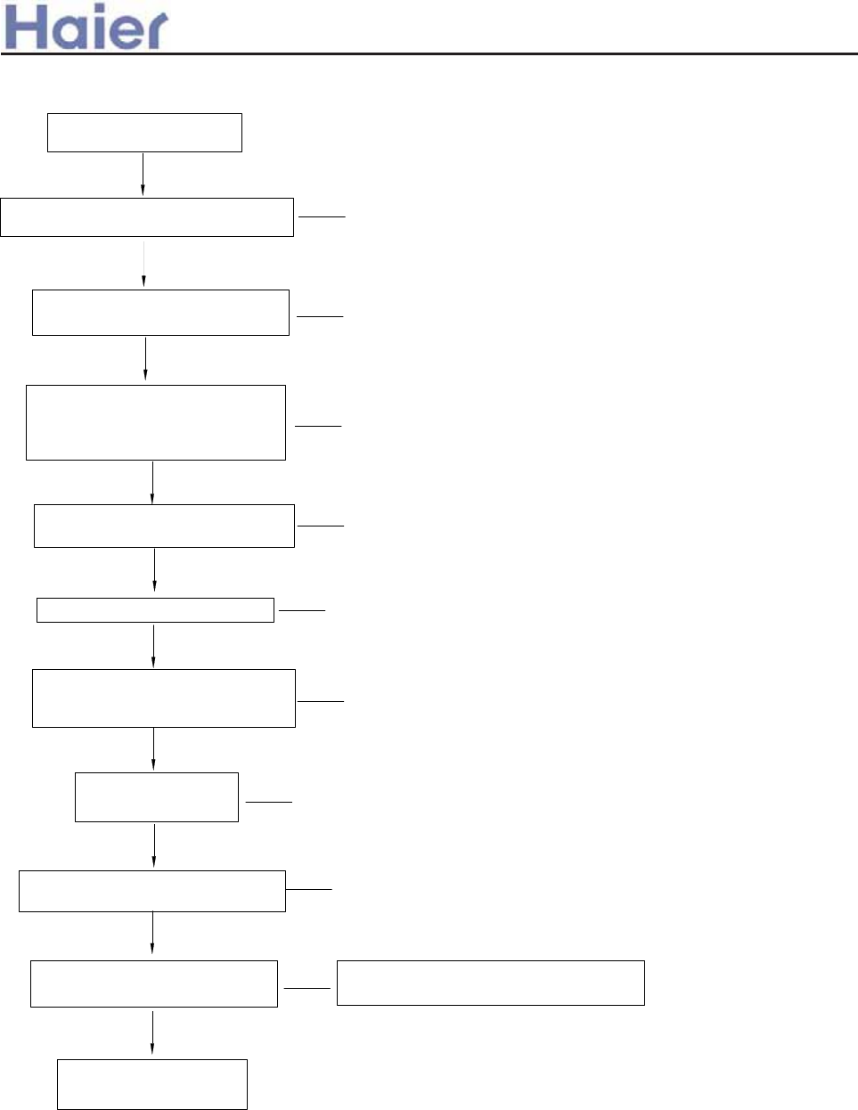
>a__WcU[S^<[c>a`V[e[a`Wc
yes
if outdoor stop valves of gas pipe
and liquid pipe are open totally Open the valves
no
Is indoor filter or heat
exchanger dirty? Cleaning
yes
yes
Repair fan motor or fan
capacitor
no
no
Repair pipe
yes
Is piping twisted or deformed?
yes
Does indoor fan work properly during
cooling cycle? Does outdoor fan work
properly during heating cycle?
no
Check if system is overfed according
to equalized pressure in halt.
yes Evacuate and recharge
no
Is reading of discharging pressure
gage oscillatory?
no Bad operation codition, such as ultra low
outdoor temperature
yes
There is air in system.
Evacuate and recharge
4)High pressure protection - Wired controller shows 53
Confirm the fault according
to the fault code list
yes
Check and reconnect
no
Are connectors of pressure switch in good
condition?
Is high side pressure switch
activated? (If not, DC voltage is 0V.)
yes
Replace PCB
no
Is the high side pressure detected by
the gage higher than threshold
value? The threshold value is
indicated on the switch
yes
Replace high pressure
switch
no
-182-
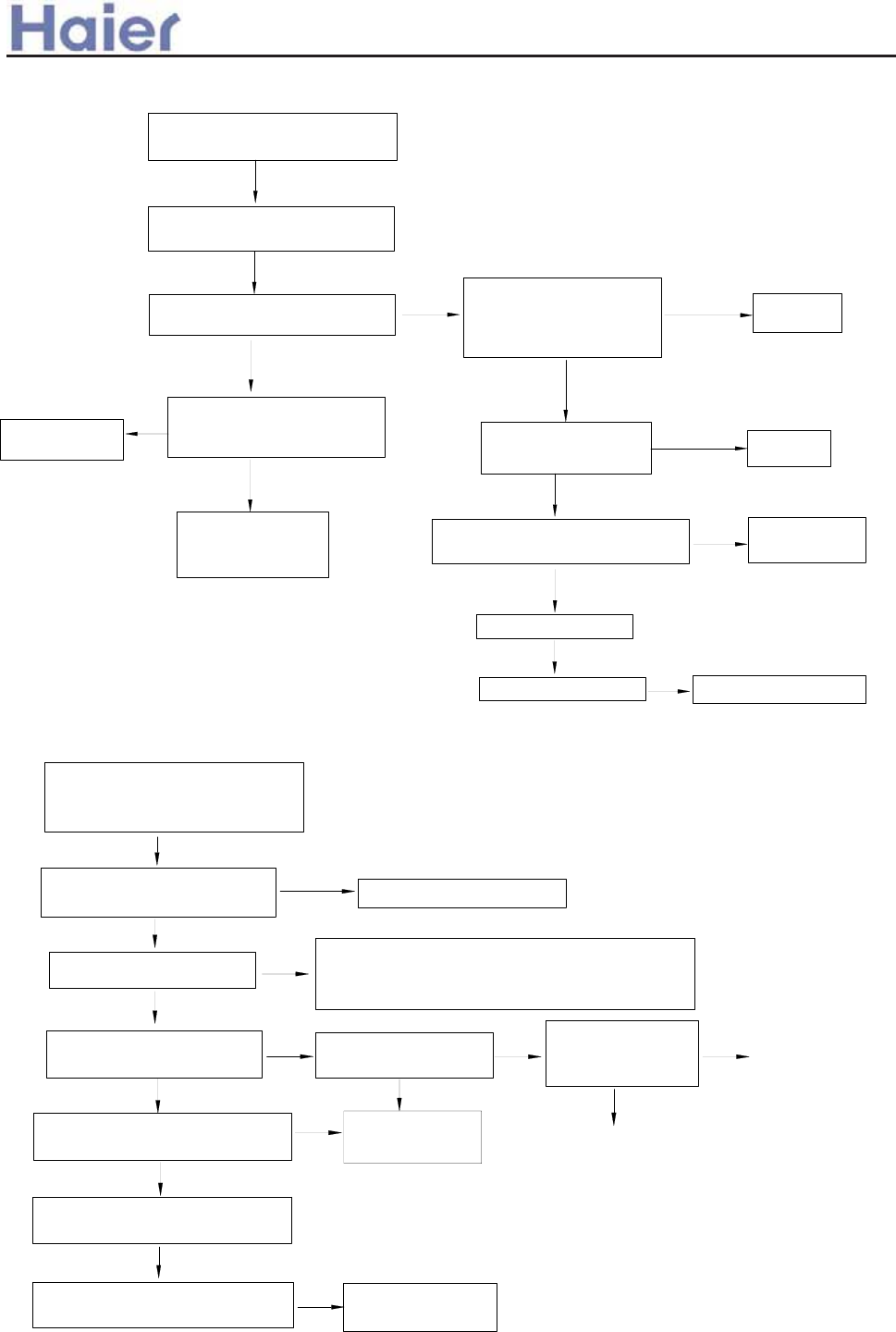
>a__WcU[S^<[c>a`V[e[a`Wc>a__WcU[S^<[c>a`V[e[a`Wc
check if indoor/outdoor PCB fuse
and transformer are normal
if failure is eliminated replace outdoor PCB
replace indoor PCB
if communication wire
is broken
Are communication wire
S and supply wires L and
N properly connected?
Grounded well?
Is communication wire too
close to power cable, which
causes interference?
Confirm the fault indicator is
communication failure
Does indoor communication
indicator flash?
check the other
reasons
no
yes
change
defective parts
re-wiring
Confirm commumication failure
according to the fault code list
5) Communication error between indoor and outdoor units - Wired controller shows 06
yes
yes
S should not share
a multicore cable
with L and N
no no
no
no
no
yes
yes
yes
re-wiring
Is supply transformer or 7812
component in good condition?
yes check if wiring
is correct
check if failure disappears after
changing transformer or PCB
no
no
check if failure disappears after
changing wired controller
yes wired controller is
broken
6) Communication failure between wired controller and indoor PCB - Wired controller shows 07
or no display on wired controller
Confirm commumication failure
according to the fault code list
or no display
yes
yes for some models, when powered on,
initialization will display 88, if initrialization
cannot finish, check indoor dip switch position
no
Is voltage between A and
B of wired controller 12V?
yes yes yes
Is voltage between B
and C fluctuating? replace PCB
no no
no
check if the wired controller
can match with indoor PCB replace wired controller
no
Is power just turned on?
check if the dip
switch position on
PCB is right
correct the position
-183-
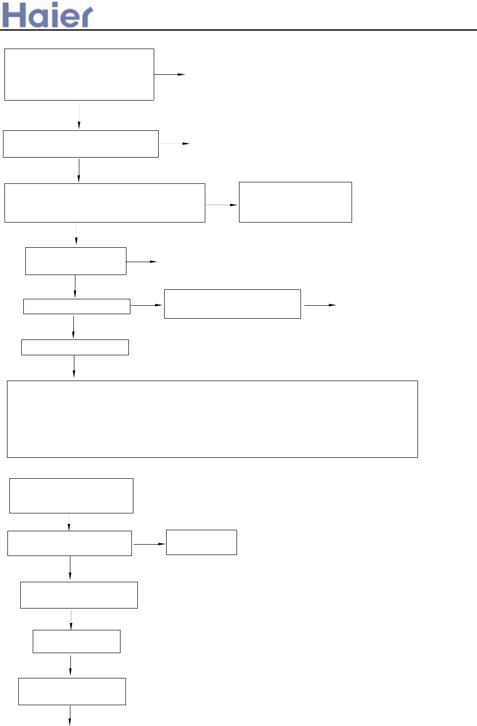
>a__WcU[S^<[c>a`V[e[a`Wc
7) High current protection in 3-phase fixed frequency models - Wired controller shows 48
Is three-phase circuit not
balanced? Is supply voltage too
low? Is supply voltage too low at
compressor start-up?
yes
no re-wiring
yes
Is compressor current more than overcurrent
protection limit? Is current detecting circuit in
good condition?
Confirm detecting circuit
is abnormal,replace
outdoor PCB
no
yes
yes replace AC contactor
yes
if compressor is normal no Is resistance of compressor
winding incorrect? Is it stuck?
yes replace compressor
yes
if pressure is normal
no
Check: 1. Is a valve in system shut off;
2. Is piping clogged;
3. Is system overfed; is there air in system;
4. (Cooling cycle) Is condenser dirty? Does outdoor fan motor run at low speed or stop?
5. (Heating cycle) Is evaporator or filter dirty? Does indoor fan motor run at low speed or stop?
6. Is ambient temperature too high? Is system overloaded?
Is power cable or compressor wire
securely connected? Properly?
Modify power supply circuit
yes
Is AC contactor in
poor contact?
Short connect that
terminal
if failure disappear after
PCB is changed
yes
no
replace PCB
yes Solve problem
accordingly
yes
Is an external alarm
connected to the system?
8) External alarm- Wired controller shows 0B
no
Is ALARM terminal in
mainboard disconnected?
An external alarm is
identified according to the
list of fault codes
-184-
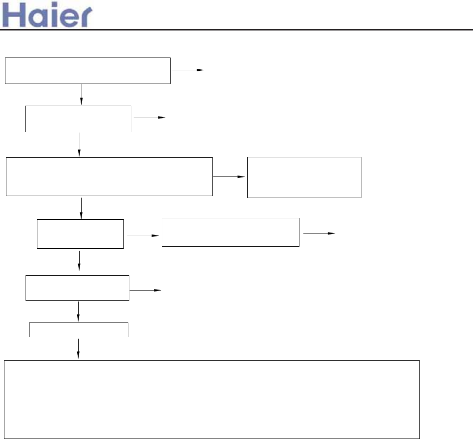
>a__WcU[S^<[c>a`V[e[a`Wc
9) Overcurrent protection for single-phase fixed frequency models- Wired controller shows 48
Is supply voltage too low? Especially
when compressor starts up? modify power supply circuit
no
no re-wiring
yes
Is compressor current more than overcurrent
protection limit? Is current detecting circuit in
good condition?
no Confirm detecting circuit
is abnormal,replace
outdoor PCB
yes
Is compressor in
good condition?
no Is resistance of compressor
winding incorrect? Is it stuck? replace compressor
yes
yes
Is running capacitor in
good condition?
no replace running capacitor
yes
Is pressure normal?
no
Check: 1. Is a valve in system shut off;
2. Is piping clogged;
3. Is system overfed; is there air in system;
4. (Cooling cycle) Is condenser dirty? Does outdoor fan motor run at low speed or stop?
5. (Heating cycle) Is evaporator or filter dirty? Does indoor fan motor run at low speed or stop?
6. Is ambient temperature too high? Is system overloaded?
yes
Is supply wire securely
connected?
-185-
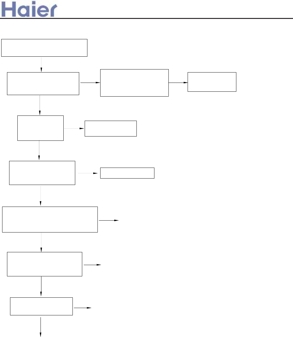
>a__WcU[S^<[c>a`V[e[a`Wc
10) Temperature cutoff protection- Wired controller shows 0D
confirm the malfunction
according to the fault code list
yes
yes
no
yes
no
yes
no
yes
no
yes
no Replace sensor
yes
Replace indoor PCB
Are indoor sensors for
ambient temperature and
coil properly located?
Is resistance of indoor
sensor correct?
Does four-way
valve work
properly?
Relocate
Replace four-way
valve
Is outdoor four-way valve
in good condition during
heating cycle?
Does small relay coil
of four-way valve have
a voltage of 12V DC?
no Relay is broken.
Replace PCB
Is indoor unit
malfunction caused by
lack of refrigerant?
charge refrigerant
Is heat exchange effect
adversely affected by heavy dust
in indoor and outdoor units?
cleaning
-186-
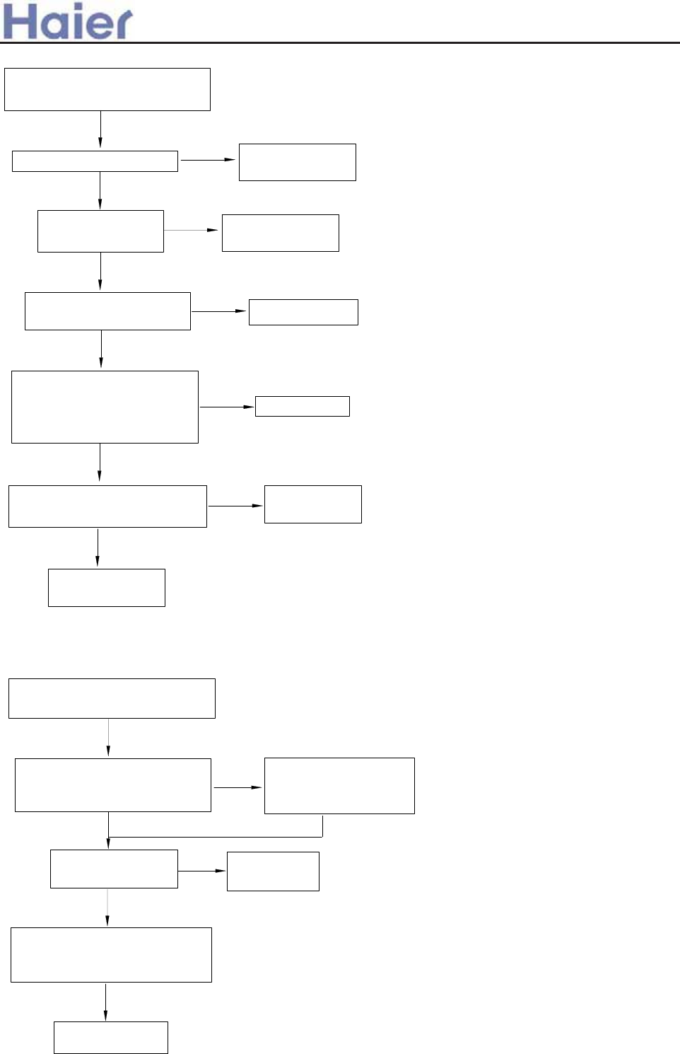
>a__WcU[S^<[c>a`V[e[a`Wc
11) Fault in drain system- Wired controller shows 08
confirm the malfunction
according to the fault code list
no
yes Replace water
pump
yes
yes Clean drain pan
no
Is float switch holder tinted
that float can't move, or too
close to pump motor that
interference arises?
yes Adjust holder
no
yes Replace float
switch
no
Replace indoor
PCB
Note: Float switch is close in normal state, when being activated, it is open.
Voltage between both ends is 0V when close, approximately 5V when open.
Unclog pipe and
water pump
Is drain pan dirty and
float switch ineffective?
Is pump motor in
good condition?
Is drain pipe clogged? yes
Check if float switch is in good
condition with multimeter
confirm the malfunction
according to the fault code list
no
no
no adjust power
supply
no
no
replace outdoor
PCB
if the failure disappear
after correcting the
wiring
Is there phase loss
or phase failure?
Is fault corrected after
sequence of either two of three
RST phases is adjusted?
Check if the phase detecting
circuit is correct according to
ourdoor wiring diagram
yes
12) Phase loss or phase failure-Wired controller shows 48
-187-
>a__WcU[S^<[c>a`V[e[a`Wc
Confirm operating
conditions
no
yes
yes
no No need to replace mainboard. The fault may
be caused by power supply
yes
no
Does the same
fault occur before?
yes
no No need to replace mainboard. Contactor
wasn't in good contact
No need to replace mainboard. (Check
operating status in details, e.g. TIMER feature,
supply failure, thunder storm, interference from
other appliances, etc.) Explain causes of fault
to user.
1.Is supply voltage acceptable?
2.Is temperature setting correct? (e.g. too high)
3.Is system in TIMER mode?
4.Is user aware of product features, etc.
Check the system thoroughly,
e.g. technical data of
components when power-off,
and voltage and current of
check points when power-on
Disconnect contactor
and reconnect it.
(check if fuse or
varistor is broken.)
Does the same
fault occur before?
Switch off air conditioner
temporarily. 6ZLWFK
on air conditioner again
after 1 minute
Does the same
fault occur before?
yes
no
Switch on air
conditioner
Is the feature not
available for present
product?
Fault confirmation
Explain product
features to user
For example: no cooling, etc.
13) Troubleshooting (before replacement of PCB)
Service call
-188-
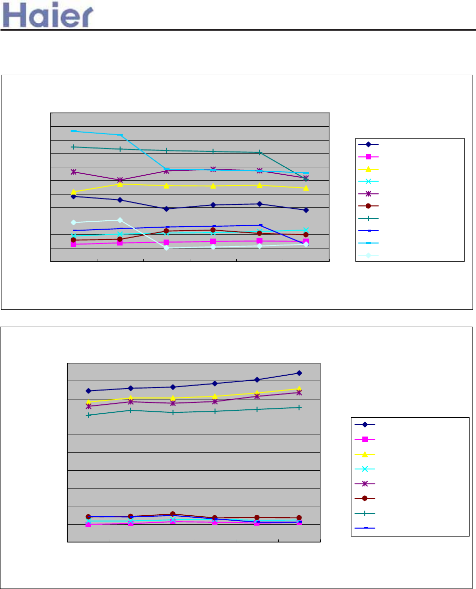
>a__WcU[S^<[c>a`V[e[a`Wc
12. Performance curves
Heating performance curves-AB182ACERA
1500
2000
2500
3000
3500
4000
4500
5000
5500
6000
6500
7000
16/10 18/12 20/14.5 21/15 22/16 24/17
indoor WB/DB
heating capacity(W)/power input(W)
-10/-11 heating capacity
-10/-11 power input
-5/-6 heating capacity
-5/-6 power input
1/0 heating capacity
1/0 power input
6/5 heating capacity
6/5 power input
10/8 heating capacity
10/8 power input
Cooling performance curves-AB182ACERA
1500
2000
2500
3000
3500
4000
4500
5000
5500
6000
6500
22/16 25/18 27/19 27/19.8 30/22 32/24
indoor DB/WB
cooling capacity(W)/power input(W)
25/16 cooling capacity
25/16 power input
30/20 cooling capacity
30/20 power input
35/24 cooling capacity
35/24 power input
40/28 cooling capacity
40/28 power input
-189-
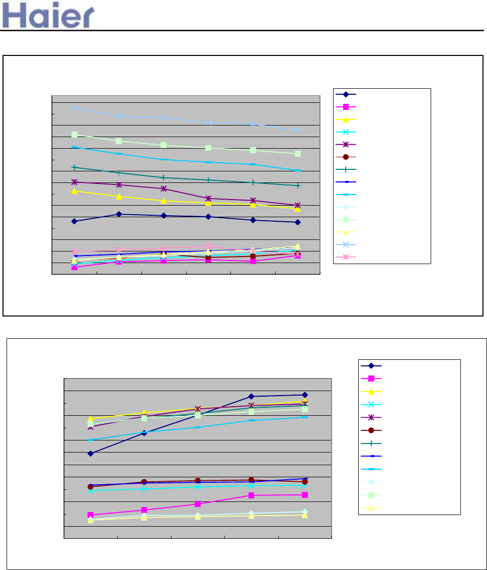
>a__WcU[S^<[c>a`V[e[a`Wc
Cooling performance curves-AC182ACERA
0
500
1000
1500
2000
2500
3000
3500
4000
4500
5000
5500
6000
6500
12/18 14/20 16/22 18/25 19/27
indoor WB/DB
cooling capacity(W)/power input(W)
20 cooling capacity
20 power input
32 cooling capacity
32 power input
35 cooling capacity
35 power input
40 cooling capacity
40 power input
-5 cooling capacity
-5 power input
-15 cooling capacity
-15 power input
Heating performance curves-AC182ACERA
1200
1700
2200
2700
3200
3700
4200
4700
5200
5700
6200
6700
7200
7700
8200
8700
16/10 18/12 20/14.5 21/15 22/16 24/17
indoor WB/DB
heating capacity(W) /power input(W)
15 heating capacity
15 power input
-7 heating capacity
-7 power input
-5 heating capacity
-5 power input
0 heating capacity
0 power input
5 heating capacity
5 power input
10 heating capacity
10 power input
15 heating capacity
15 power input
-190-
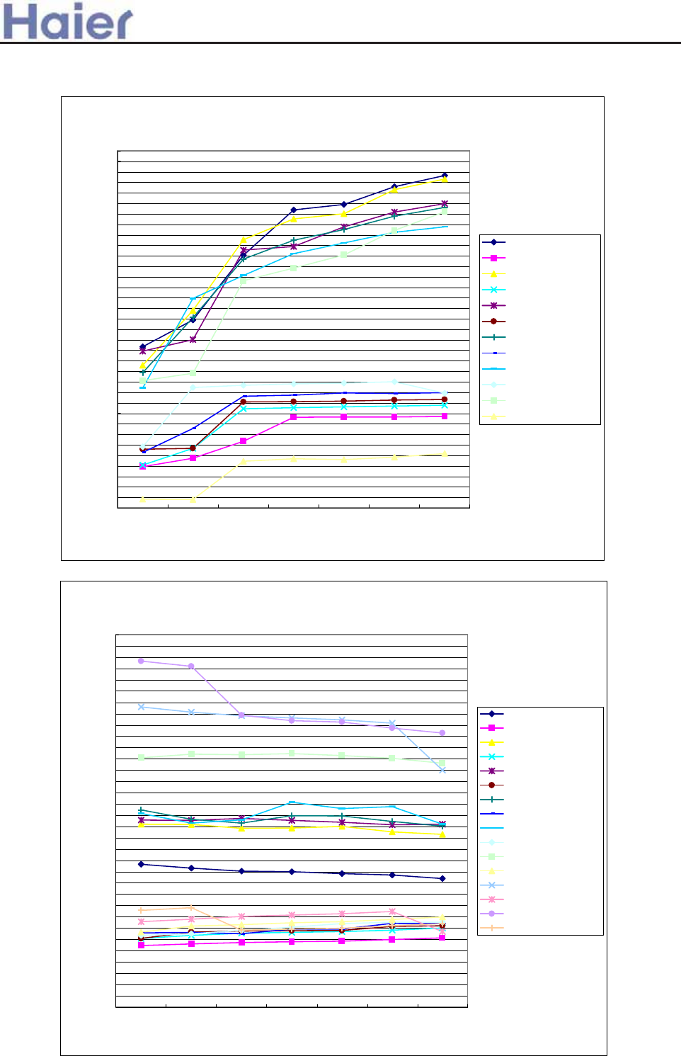
>a__WcU[S^<[c>a`V[e[a`Wc
AU182AFERA+AS182AVERA:
performance curves in cooling mode
0
200
400
600
800
1000
1200
1400
1600
1800
2000
2200
2400
2600
2800
3000
3200
3400
3600
3800
4000
4200
4400
4600
4800
5000
5200
5400
5600
5800
6000
6200
6400
6600
6800
12/18 14/20 16/22 18/25 19/27 22/30 24/32
indoor WB/DB
cooling capacity(KW)
20 cooling capacity
20 power input
25 cooling capacity
25 power input
32 cooling capacity
32 power input
35 cooling capacity
35 power input
40 cooling capacity
40 power input
-5 cooling capacity
-5 power input
performance curves in heating mode
0
300
600
900
1200
1500
1800
2100
2400
2700
3000
3300
3600
3900
4200
4500
4800
5100
5400
5700
6000
6300
6600
6900
7200
7500
7800
8100
8400
8700
9000
9300
9600
9900
16/10 18/12 20/14.5 21/15 22/16 24/17 26/18
indoor WB/DB
heating capacity (KW)
-15/-16 heating capacity
-15/-16 power input
-6/-7 heating capacity
-6/-7 power input
-4/-5 heating capacity
-4/-5 power input
-1/-2 heating capacity
-1/-2 power input
1/0 heating capacity
1/0 power input
7/6 heating capacity
7/6 power input
12/10 heating capacity
12/10 power input
16/15 heating capacity
16/15 power input
-191-
>a__WcU[S^<[c>a`V[e[a`Wc
AU182AFERA+AD182AMERA:
performance curves in cooling mode
0
200
400
600
800
1000
1200
1400
1600
1800
2000
2200
2400
2600
2800
3000
3200
3400
3600
3800
4000
4200
4400
4600
4800
5000
5200
5400
5600
5800
6000
6200
6400
6600
6800
7000
7200
7400
7600
12/18 14/20 16/22 18/25 19/27 22/30 24/32
indoor WB/DB
cooling capacity(KW)
20 cooling capacity
20 power input
25 cooling capacity
25 power input
32 cooling capacity
32 power input
35 cooling capacity
35 power input
40 cooling capacity
40 power input
-5 cooling capacity
-5 power input
performance curves in heating mode
0
300
600
900
1200
1500
1800
2100
2400
2700
3000
3300
3600
3900
4200
4500
4800
5100
5400
5700
6000
6300
6600
6900
7200
7500
7800
8100
8400
8700
9000
9300
9600
9900
10200
10500
10800
16/10 18/12 20/14.5 21/15 22/16 24/17 26/18
indoor WB/DB
heating capacity (KW)
-6/-7 heating capacity
-6/-7 power input
-4/-5 heating capacity
-4/-5 power input
-1/-2 heating capacity
-1/-2 power input
1/0 heating capacity
1/0 power input
7/6 heating capacity
7/6 power input
6/5 heating capacity
6/5 power input
12/10 heating capacity
12/10 power input
16/15 heating capacity
16/15 power input
-192-
>a__WcU[S^<[c>a`V[e[a`Wc
cooling capacity/power input/air flow and external static pressure curves
600
900
1200
1500
1800
2100
2400
2700
3000
3300
3600
3900
4200
4500
4800
5100
5400
5700
6000
6300
6600
6900
indoor 27/19
outdoor 35/24 (inverter
70Hz)
indoor 20/14.5
outdoor 7/6 (inverter
68Hz)
indoor 27/19
outdoor 35/24 (fixed
frequency 55Hz)
indoor 20/14.5
outdoor 7/6 (fixed
frequency 58Hz)
operation condition
performance valu
e
0Pa cooling capacity
0Pa power input
0Pa air flow
10Pa cooling capacity
10Pa power input
10Pa air flow
20Pa cooling capacity
20Pa power input
20Pa air flow
30Pa cooling capacity
30Pa power input
30Pa air flow
40Pa cooling capacity
40Pa power input
40Pa air flow
50Pa cooling capacity
50Pa power input
50Pa air flow
-193-
>a__WcU[S^<[c>a`V[e[a`Wc
42
AC362AFERA heating capacity curves
0
500
1000
1500
2000
2500
3000
3500
4000
4500
5000
5500
6000
6500
7000
7500
8000
8500
9000
9500
10000
10500
11000
11500
12000
12500
13000
16/10 18/12 20/14.5 21/15 22/16 24/17 26/18
indoor WB/DB
-6/-7 heating
capacity
-6/-7 power
input
-4/-5 heating
capacity
-4/-5 power
input
0/-1 heating
capacity
0/-1 power input
2/1 heating
capacity
2/1 power input
6/5 heating
capacity
6/5 power input
7/6 heating
capacity
7/6 power input
12/10 heating
capacity
12/10 power
input
16/15 heating
capacity
16/15 power
input
43
AC362AFERA cooling capacity curves
0
500
1000
1500
2000
2500
3000
3500
4000
4500
5000
5500
6000
6500
7000
7500
8000
8500
9000
9500
10000
10500
11000
11500
12000
12500
13000
12/18 14/20 16/22 18/25 19/27 22/30 24/32
indoor WB/DB
cooling capacity(W)/power input(W)
20 cooling capacity
20 power input
25 cooling capacity
25 power input
32 cooling capacity
32 power input
35 cooling capacity
35 power input
40 cooling capacity
40 power input
AC362AFERA
-194-
>a__WcU[S^<[c>a`V[e[a`Wc
AD362AMERA cooling(heating) capacity -Esp. curves
0
500
1000
1500
2000
2500
3000
3500
4000
4500
5000
5500
6000
6500
7000
7500
8000
8500
9000
9500
10000
10500
11000
11500
indoor: 27/19 outdoor: 35/24
(FQY: 85HZ) cooling
indoor: 20/14.5 outdoor: 7/6
(FQY: 90HZ) heating
0pa cooling
capacity
0pa power input
0pa EER
COP
10pa cooling
capacity
10pa air flow
10pa EER
COP
20pa power
input
20pa air flow
30pa cooling
capacity
30pa power
input
30pa EER
COP
40pa cooling
capacity
40pa aier flow
40pa EER
COP
50pa power
input
50pa air flow
AD362AMERA
-195-
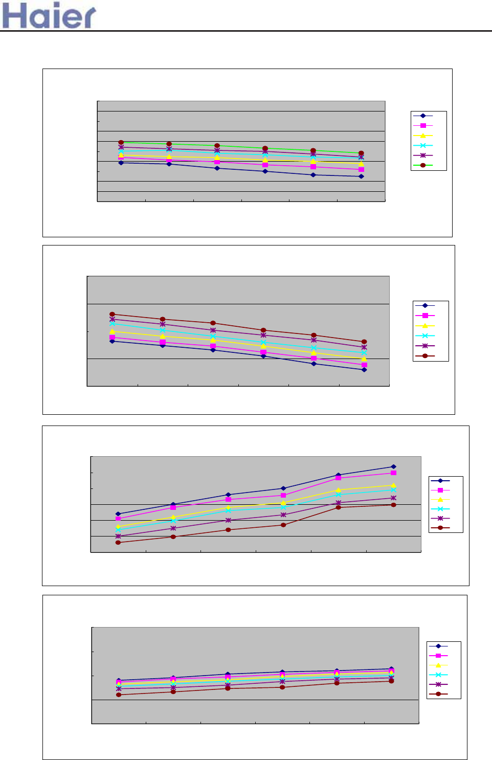
>a__WcU[S^<[c>a`V[e[a`Wc
Heating capacity curves
3000
3500
4000
4500
5000
5500
6000
6500
7000
7500
8000
16/10 18/12 20/14.5 22/16 24/17 26/18
indoor DB/WB
Heating capacity (W)
-7
-5
0
7
10
15
Power input curves in heating mode
2.5
3.0
3.5
4.0
4.5
16/10 18/12 20/14.5 22/16 24/17 26/18
indoor DB/WB
COP
-7
-5
0
7
10
15
Cooling capacity curves
4000
4500
5000
5500
6000
6500
7000
20/14 22/16 25/18 27/19 30/22 32/24
indoor DB/WB
Cooling capacity (W)
-5
5
15
25
35
43
Power input curves in cooling mode
1.00
2.00
3.00
4.00
5.00
20/14 22/16 25/18 27/19 30/22 32/24
indoor DB/WB
EER)
-5
5
15
25
35
43
AU182AEEAA
-196-
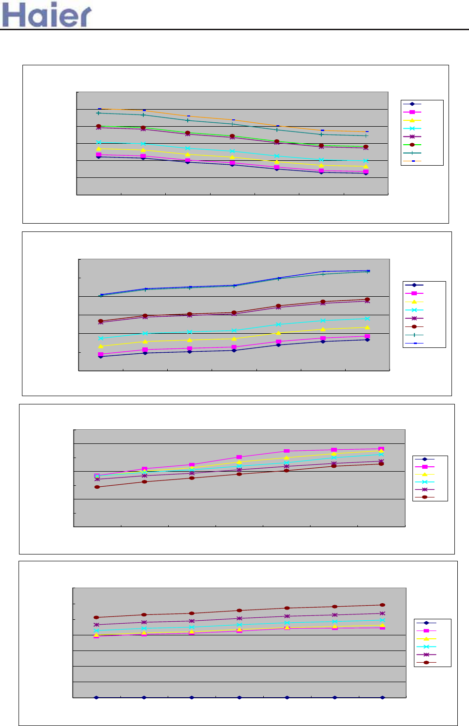
>a__WcU[S^<[c>a`V[e[a`Wc
Heating capacity curves
4000
5000
6000
7000
8000
9000
10000
16/10 18/12 20/14.5 21/15 22/16 24/17 26/18
indoor DB/WB
Heating capacity (W)
-6/-7
-4/-5
-1/-2
1/0
6/5
7/6
12/10
16/15
24
Power input curves in heating mode
1700
1900
2100
2300
2500
2700
2900
16/10 18/12 20/14.5 21/15 22/16 24/17 26/18
indoor DB/WB
Power input (W)
-6/-7
-4/-5
-1/-2
1/0
6/5
7/6
12/10
16/15
Cooling capacity curves
3000
4000
5000
6000
7000
8000
9000
10000
18/12 20/14 22/16 25/18 27/19 30/22 32/24
indoor DB/WB
Cooling capacity (W)
-5
20
25
32
35
40
Power input curves in cooling mode
0
500
1000
1500
2000
2500
3000
3500
18/12 20/14 22/16 25/18 27/19 30/22 32/24
indoor DB/WB
Power input (W)
-5
20
25
32
35
40
AU242AGEAA
-197-
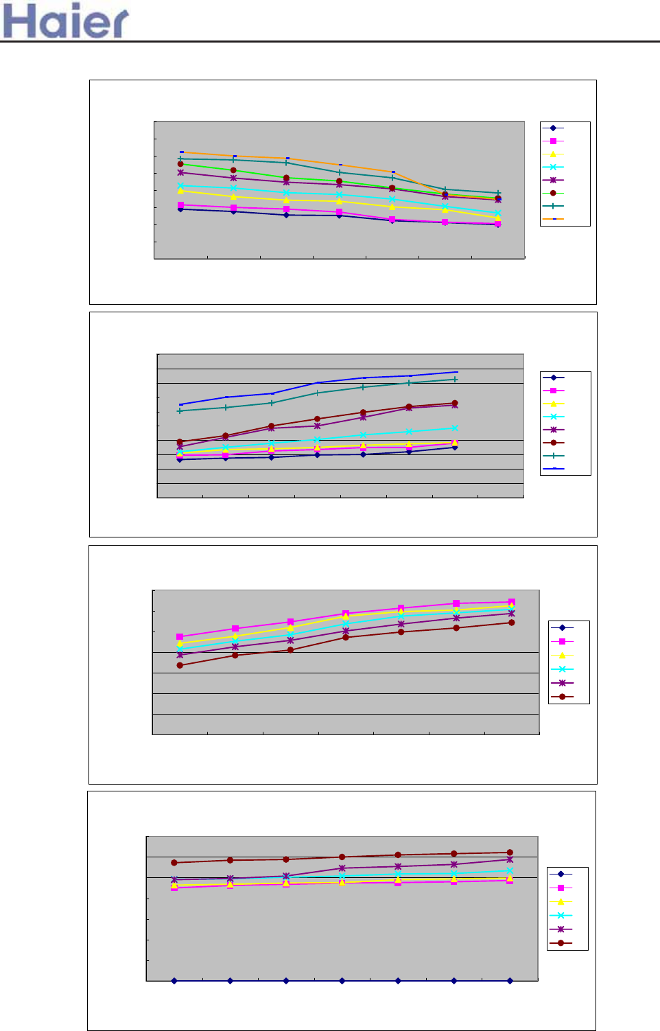
>a__WcU[S^<[c>a`V[e[a`Wc
Heating capacity curves
4000
5000
6000
7000
8000
9000
10000
11000
12000
16/10 18/12 20/14.5 21/15 22/16 24/17 26/18
indoor DB/WB
Heating capacity (W)
-6/-7
-4/-5
-1/-2
1/0
6/5
7/6
12/10
16/15
53
Power input curves in heating mode
1700
1900
2100
2300
2500
2700
2900
3100
3300
3500
3700
16/10 18/12 20/14.5 21/15 22/16 24/17 26/18
indoor DB/WB
Power input (W)
-6/-7
-4/-5
-1/-2
1/0
6/5
7/6
12/10
16/15
Cooling capacity curves
3000
4000
5000
6000
7000
8000
9000
10000
18/12 20/14 22/16 25/18 27/19 30/22 32/24
indoor DB/WB
Cooling capacity (W)
-5
20
25
32
35
40
Power input curves in cooling mode
0
500
1000
1500
2000
2500
3000
3500
18/12 20/14 22/16 25/18 27/19 30/22 32/24
indoor DB/WB
Power input (W)
-5
20
25
32
35
40
AU282AHEAA
-198-
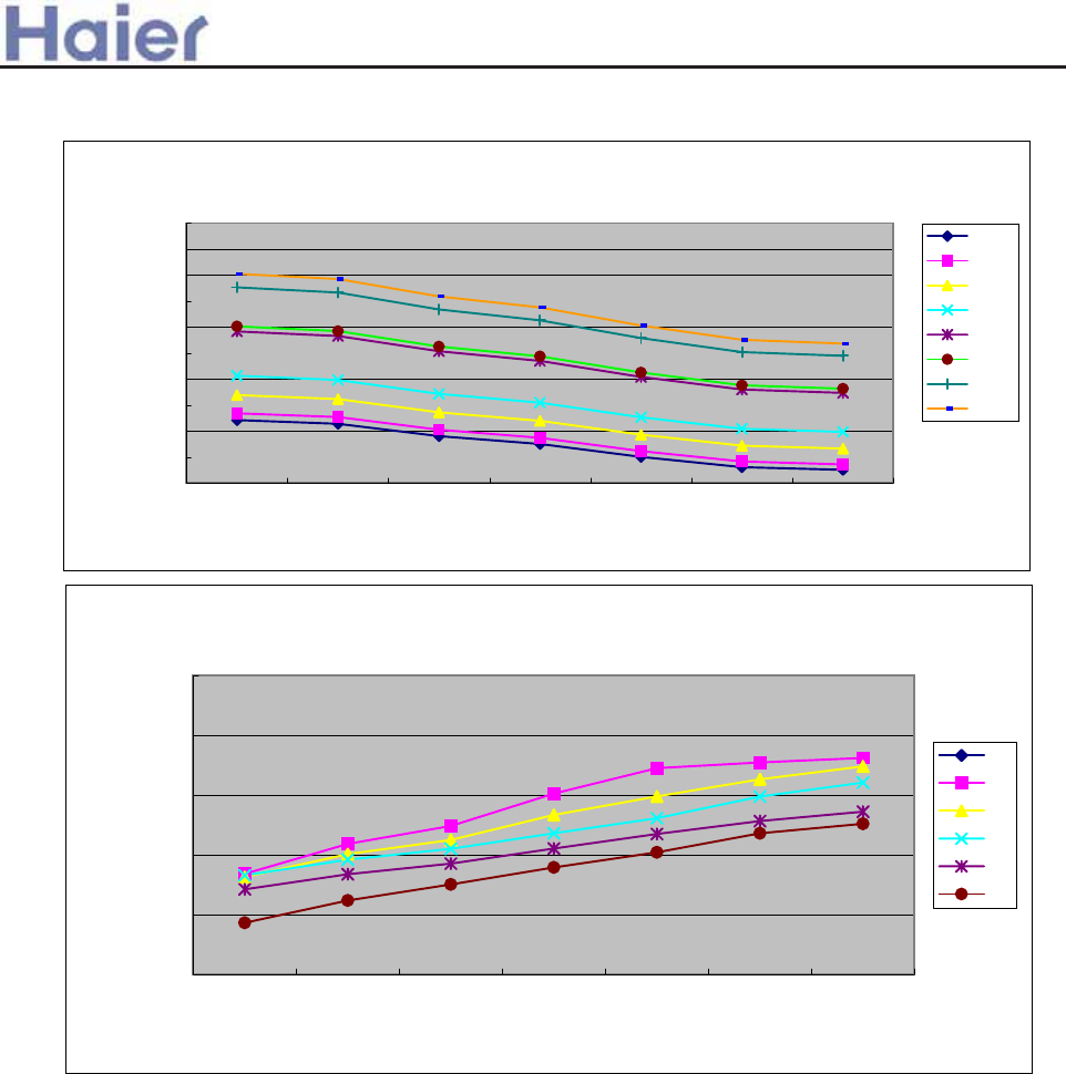
>a__WcU[S^<[c>a`V[e[a`Wc
AU362AIEAA
Heating capacity curves
8000
8500
9000
9500
10000
10500
11000
11500
12000
12500
13000
16/10 18/12 20/14.5 21/15 22/16 24/17 26/18
indoor DB/WB
Heating capacity (W)
-6/-7
-4/-5
-1/-2
1/0
6/5
7/6
12/10
16/15
Cooling capacity curves
8000
9000
10000
11000
12000
13000
18/12 20/14 22/16 25/18 27/19 30/22 32/24
indoor DB/WB
Cooling capacity (W)
-5
20
25
32
35
40
-199-
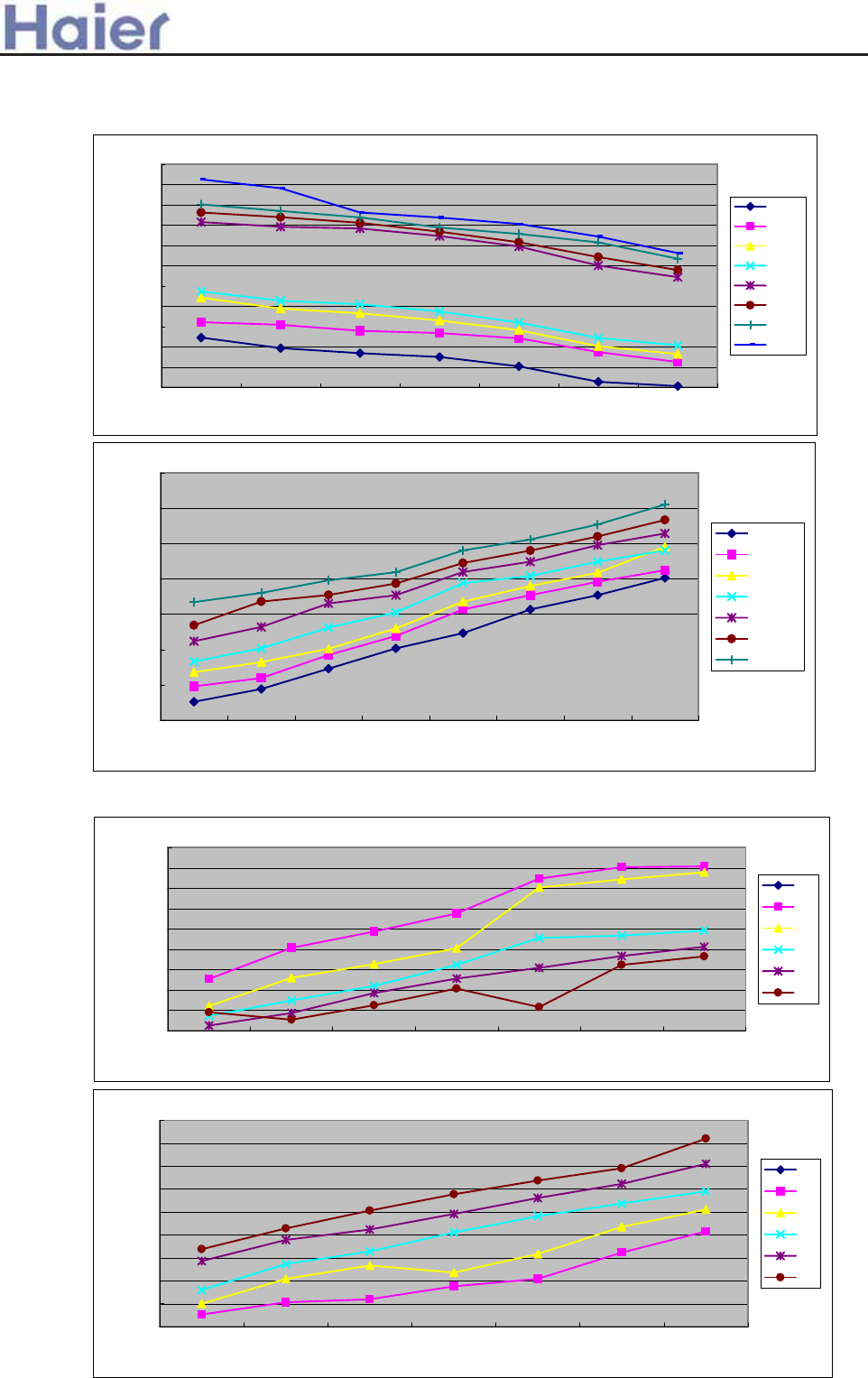
>a__WcU[S^<[c>a`V[e[a`Wc
AU42NALEAA
10000
10500
11000
11500
12000
12500
13000
13500
14000
14500
15000
15500
16/10 18/12 20/14.5 21/15 22/16 24/17 26/18
-6/-7
-4/-5
-1/-2
1/0
6/5
7/6
12/10
16/15
4400
4600
4800
5000
5200
5400
5600
5800
-6/-7 -4/-5 -1/-2 1/0 6/5 7/6 12/10 16/15
16/10
18/12
20/14.5
21/15
22/16
24/17
26/18
Heating capacity curves
Cooling capacity curves
11500
11750
12000
12250
12500
12750
13000
13250
13500
13750
18/12 20/14 22/16 25/18 27/19 30/22 32/24
-5
20
25
32
35
40
4300
4400
4500
4600
4700
4800
4900
5000
5100
5200
18/12 20/14 22/16 25/18 27/19 30/22 32/24
-5
20
25
32
35
40
-200-
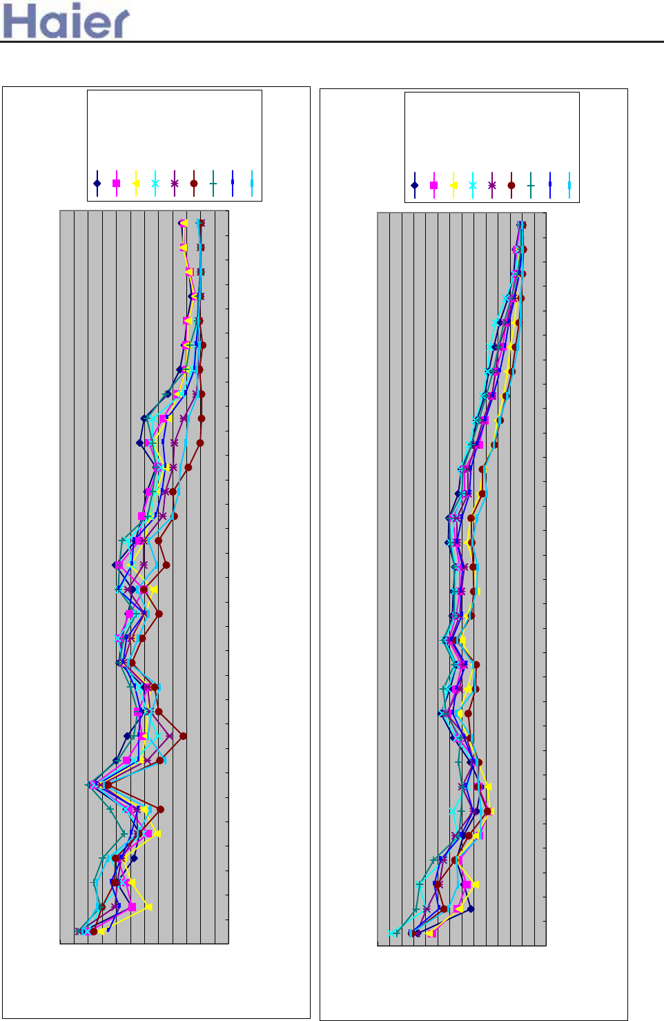
>a__WcU[S^<[c>a`V[e[a`Wc
13. Noise level
1/3 octave band noise level-AB182ACERA
0.0
5.0
10.0
15.0
20.0
25.0
30.0
35.0
40.0
45.0
50.0
55.0
60.0
25.0
31.5
40.0
50.0
63.0
80.0
100.0
125.0
160.0
200.0
250.0
315.0
400.0
500.0
630.0
800.0
1000.0
1250.0
1600.0
2000.0
2500.0
3150.0
4000.0
5000.0
6300.0
8000.0
10000.0
12500.0
16000.0
20000.0
third octave band frequency Hz
Sound pressure level DB
cooling high
cooling med
cooling low
fan high
fan med
fan low
heating high
heating med
heating low
1/3 octave band noise level-AC182ACERA
0.0
5.0
10.0
15.0
20.0
25.0
30.0
35.0
40.0
45.0
50.0
55.0
60.0
65.0
70.0
25.0
31.5
40.0
50.0
63.0
80.0
100.0
125.0
160.0
200.0
250.0
315.0
400.0
500.0
630.0
800.0
1000.0
1250.0
1600.0
2000.0
2500.0
3150.0
4000.0
5000.0
6300.0
8000.0
10000.0
12500.0
16000.0
20000.0
third octave band frequency Hz
Sound pressure level DB
cooling high
cooling med
cooling low
fan high
fan med
fan low
heating high
heating med
heating low
-201-
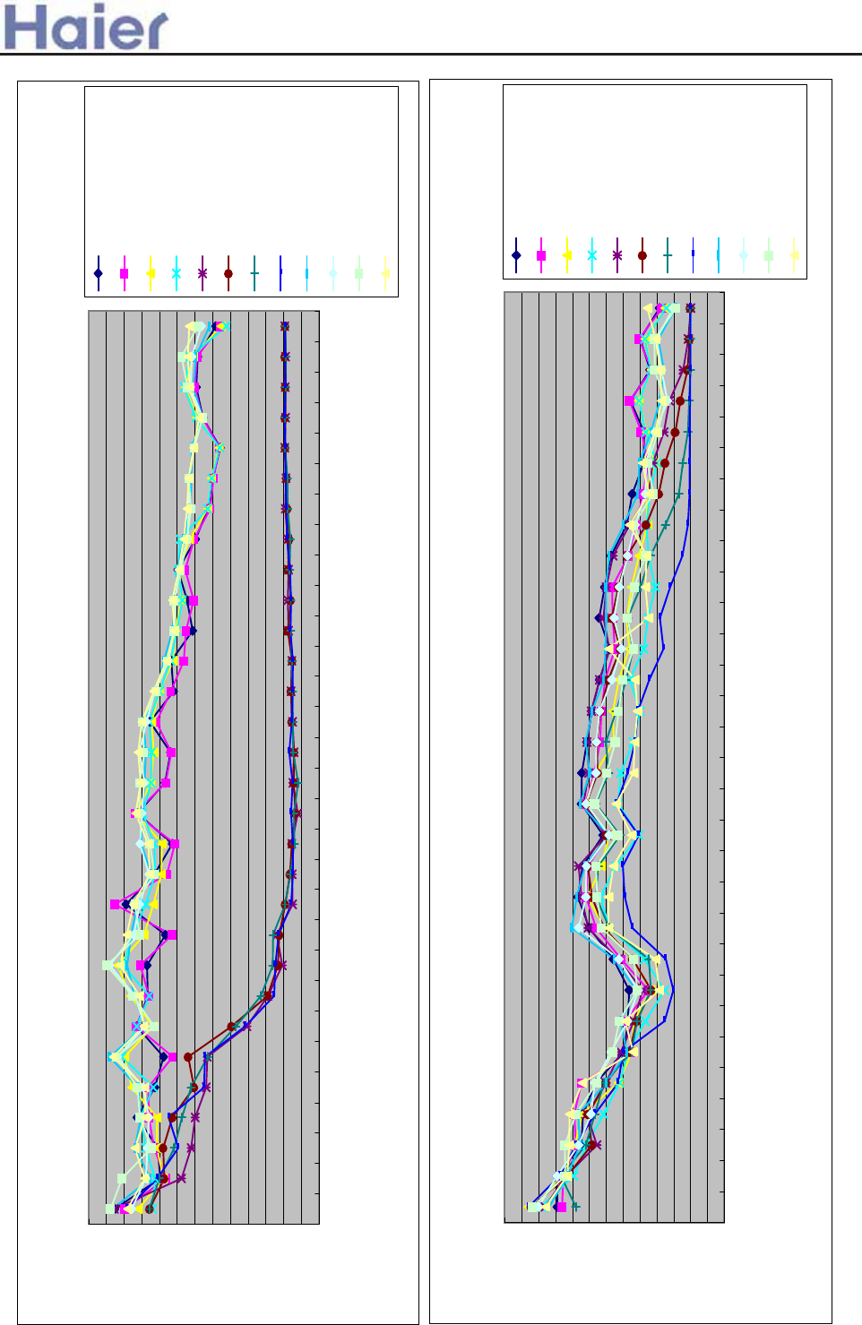
>a__WcU[S^<[c>a`V[e[a`Wc
1/3 octave band noise level-AU182AFERA
0.0
5.0
10.0
15.0
20.0
25.0
30.0
35.0
40.0
45.0
50.0
55.0
60.0
65.0
25.0
31.5
40.0
50.0
63.0
80.0
100.0
125.0
160.0
200.0
250.0
315.0
400.0
500.0
630.0
800.0
1000.0
1250.0
1600.0
2000.0
2500.0
3150.0
4000.0
5000.0
6300.0
8000.0
10000.0
12500.0
16000.0
20000.0
third octave band frequency Hz
sound pressure level DB
cooling superhigh
cooling high
cooling med
cooling low
fan superhigh
fan high
fan med
fan low
heating superhigh
heating high
heating med
heating low
1/3 octave band noise level-AD182AMERA
0.0
5.0
10.0
15.0
20.0
25.0
30.0
35.0
40.0
45.0
50.0
55.0
60.0
65.0
25.0
31.5
40.0
50.0
63.0
80.0
100.0
125.0
160.0
200.0
250.0
315.0
400.0
500.0
630.0
800.0
1000.0
1250.0
1600.0
2000.0
2500.0
3150.0
4000.0
5000.0
6300.0
8000.0
10000.0
12500.0
16000.0
20000.0
third octave band frequency Hz
sound pressure level DB
cooling superhigh
cooling high
cooling med
cooling low
fan superhigh
fan high
fan med
fan low
heating superhigh
heating high
heating med
heating low
--202-
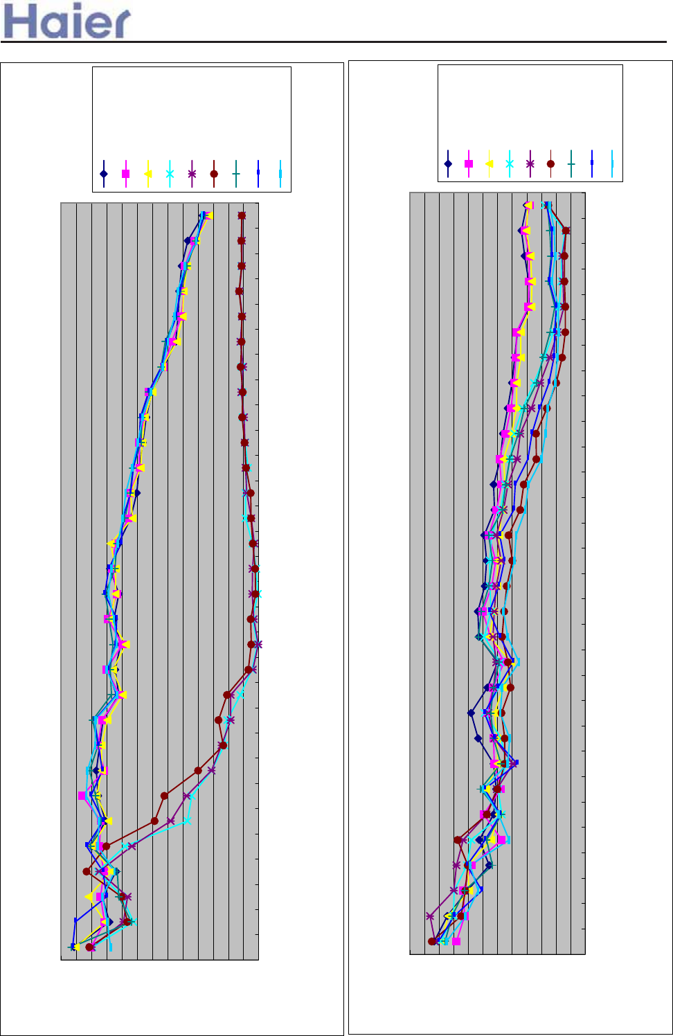
>a__WcU[S^<[c>a`V[e[a`Wc
1/3 octave band noise level-AU182AFERA
0.0
5.0
10.0
15.0
20.0
25.0
30.0
35.0
40.0
45.0
50.0
55.0
60.0
65.0
25.0
31.5
40.0
50.0
63.0
80.0
100.0
125.0
160.0
200.0
250.0
315.0
400.0
500.0
630.0
800.0
1000.0
1250.0
1600.0
2000.0
2500.0
3150.0
4000.0
5000.0
6300.0
8000.0
10000.0
12500.0
16000.0
20000.0
third octave band frequency Hz
sound pressure level DB
cooling high
cooling med
cooling low
fan high
fan med
fan low
heating high
heating med
heating low
1/3 octave band noise level-AS182AVERA
0.0
5.0
10.0
15.0
20.0
25.0
30.0
35.0
40.0
45.0
50.0
55.0
60.0
25.0
31.5
40.0
50.0
63.0
80.0
100.0
125.0
160.0
200.0
250.0
315.0
400.0
500.0
630.0
800.0
1000.0
1250.0
1600.0
2000.0
2500.0
3150.0
4000.0
5000.0
6300.0
8000.0
10000.0
12500.0
16000.0
20000.0
third octave band frequency Hz
Sound pressure level DB
cooling high
cooling med
cooling low
fan high
fan med
fan low
heating high
heating med
heating low
-203-
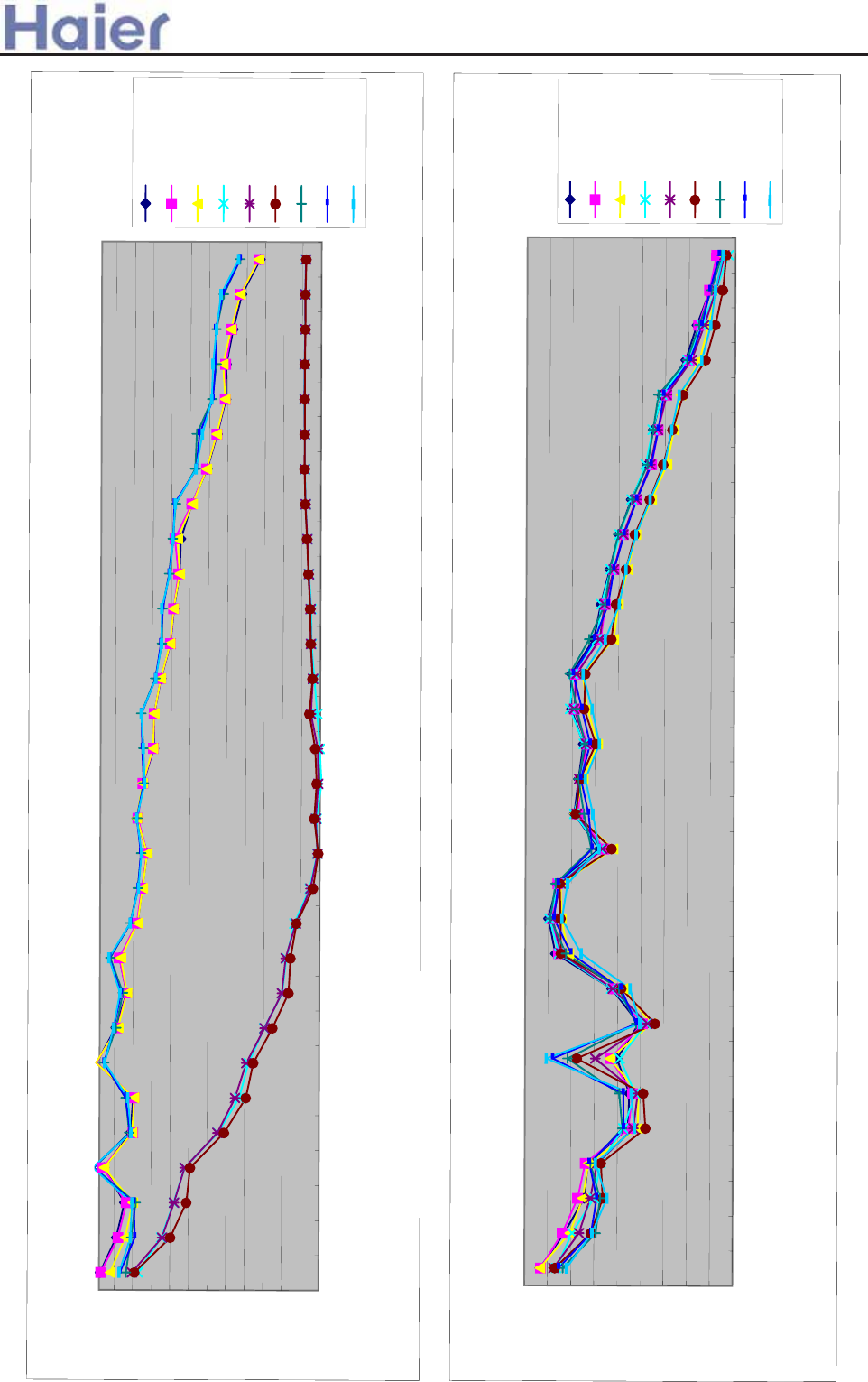
>a__WcU[S^<[c>a`V[e[a`Wc
1/3 octave band noise level-AU242AGERA
1.0
6.0
11.0
16.0
21.0
26.0
31.0
36.0
41.0
46.0
51.0
56.0
25.0
31.5
40.0
50.0
63.0
80.0
100.0
125.0
160.0
200.0
250.0
315.0
400.0
500.0
630.0
800.0
1000.0
1250.0
1600.0
2000.0
2500.0
3150.0
4000.0
5000.0
6300.0
8000.0
10000.0
12500.0
16000.0
20000.0
third octave band frequency Hz
sound pressure level DB
cooling high
cooling med
cooling low
fan high
fan med
fan low
heating high
heating med
heating low
1/3 octave band noise level-AC242ACERA
8.0
13.0
18.0
23.0
28.0
33.0
38.0
43.0
48.0
53.0
25.0
31.5
40.0
50.0
63.0
80.0
100.0
125.0
160.0
200.0
250.0
315.0
400.0
500.0
630.0
800.0
1000.0
1250.0
1600.0
2000.0
2500.0
3150.0
4000.0
5000.0
6300.0
8000.0
10000.0
12500.0
16000.0
20000.0
third octave band frequency Hz
Sound pressure level DB
cooling high
cooling med
cooling low
fan high
fan med
fan low
heating high
heating med
heating low
-204-
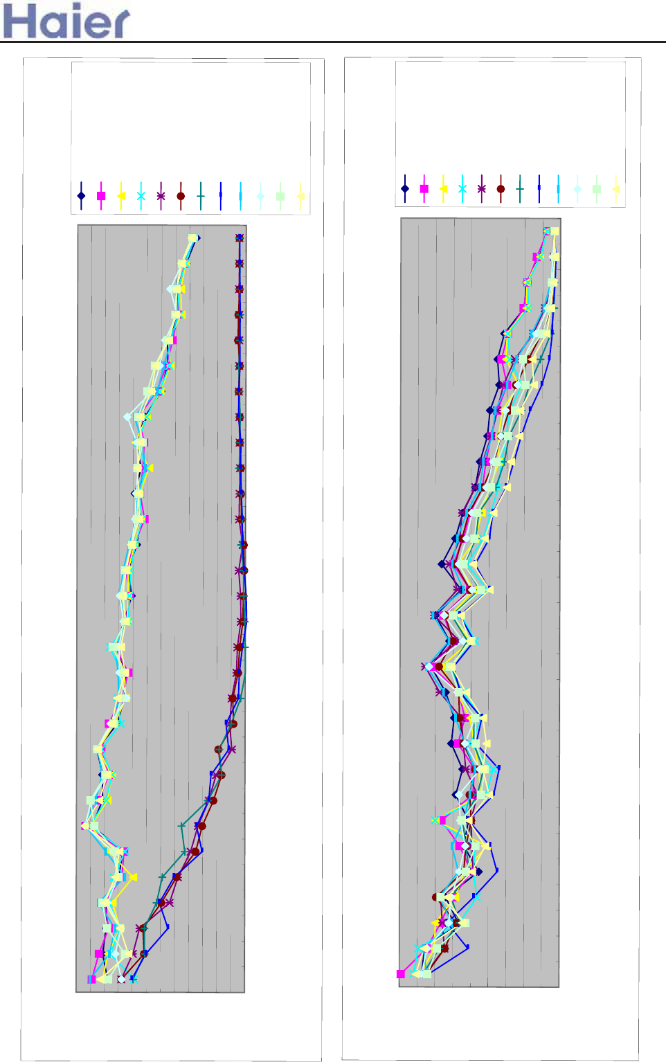
>a__WcU[S^<[c>a`V[e[a`Wc
1/3 octave band noise level-AU242AGERA
5.0
10.0
15.0
20.0
25.0
30.0
35.0
40.0
45.0
50.0
55.0
60.0
65.0
25.0
31.5
40.0
50.0
63.0
80.0
100.0
125.0
160.0
200.0
250.0
315.0
400.0
500.0
630.0
800.0
1000.0
1250.0
1600.0
2000.0
2500.0
3150.0
4000.0
5000.0
6300.0
8000.0
10000.0
12500.0
16000.0
20000.0
third octave band frequency Hz
sound pressure level DB
cooling super high
cooling high
cooling med
cooling low
fan super high
fan high
fan med
fan low
heating super high
heating high
heating med
heating low
1/3 octave band noise level-AD242AMERA
8.0
13.0
18.0
23.0
28.0
33.0
38.0
43.0
48.0
53.0
25.0
31.5
40.0
50.0
63.0
80.0
100.0
125.0
160.0
200.0
250.0
315.0
400.0
500.0
630.0
800.0
1000.0
1250.0
1600.0
2000.0
2500.0
3150.0
4000.0
5000.0
6300.0
8000.0
10000.0
12500.0
16000.0
20000.0
third octave band frequency Hz
Sound pressure level DB
cooling super high
cooling high
cooling med
cooling low
fan super high
fan high
fan med
fan low
heating super high
heating high
heating med
heating low
-205-
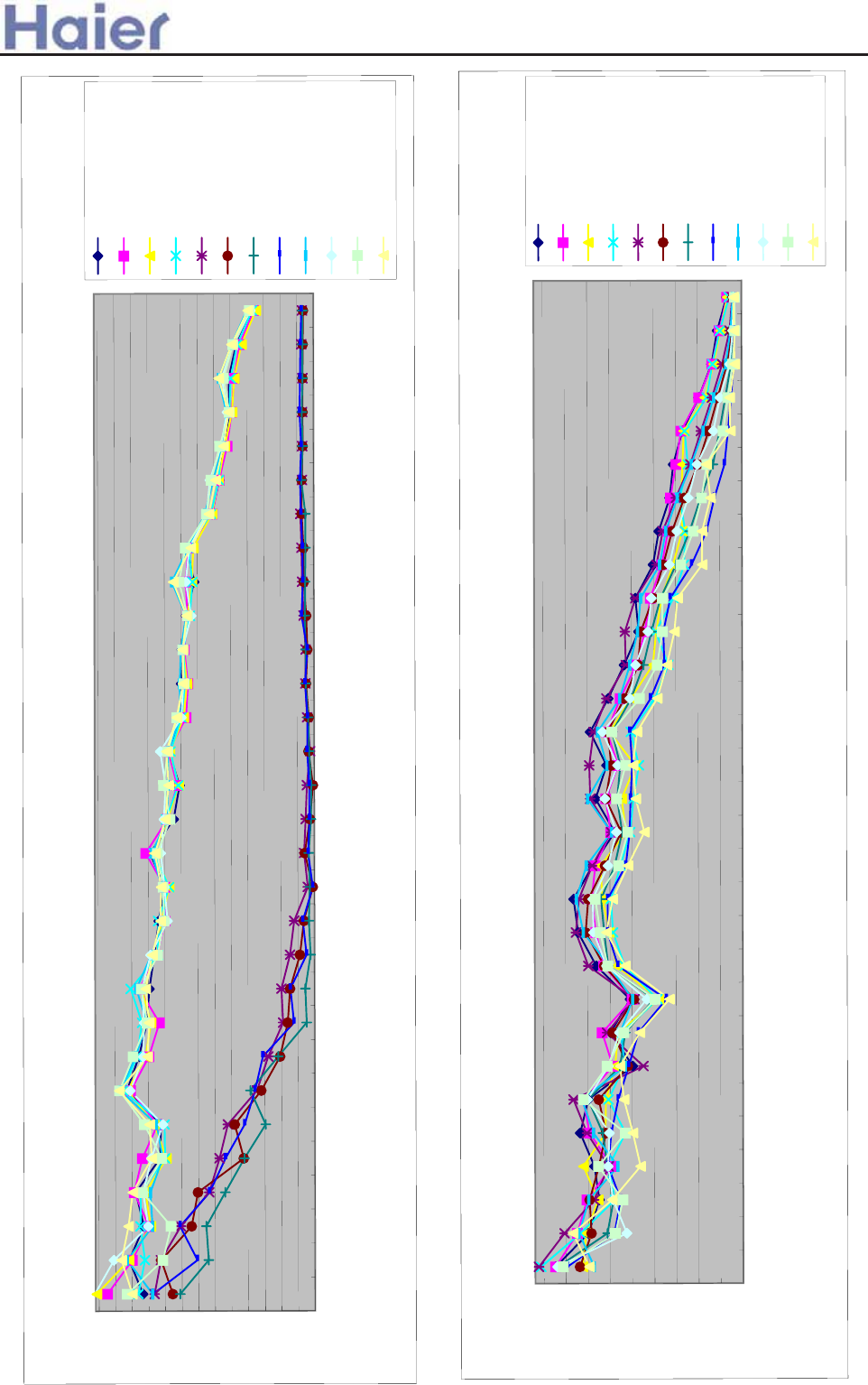
>a__WcU[S^<[c>a`V[e[a`Wc
1/3 octave band noise level-AU242AGERA
4
9
14
19
24
29
34
39
44
49
54
59
64
69
25.0
31.5
40.0
50.0
63.0
80.0
100.0
125.0
160.0
200.0
250.0
315.0
400.0
500.0
630.0
800.0
1000.0
1250.0
1600.0
2000.0
2500.0
3150.0
4000.0
5000.0
6300.0
8000.0
10000.0
12500.0
16000.0
20000.0
third octave band frequency Hz
sound pressure level DB
cooling super high
cooling high
cooling med
cooling low
fan super high
fan high
fan med
fan low
heating super high
heating high
heating med
heating low
1/3 octave band noise level-AD242ALERA
8.0
13.0
18.0
23.0
28.0
33.0
38.0
43.0
48.0
53.0
25.0
31.5
40.0
50.0
63.0
80.0
100.0
125.0
160.0
200.0
250.0
315.0
400.0
500.0
630.0
800.0
1000.0
1250.0
1600.0
2000.0
2500.0
3150.0
4000.0
5000.0
6300.0
8000.0
10000.0
12500.0
16000.0
20000.0
third octave band frequency Hz
Sound pressure level DB
cooling super high
cooling high
cooling med
cooling low
fan super high
fan high
fan med
fan low
heating super high
heating high
heating med
heating low
-206-
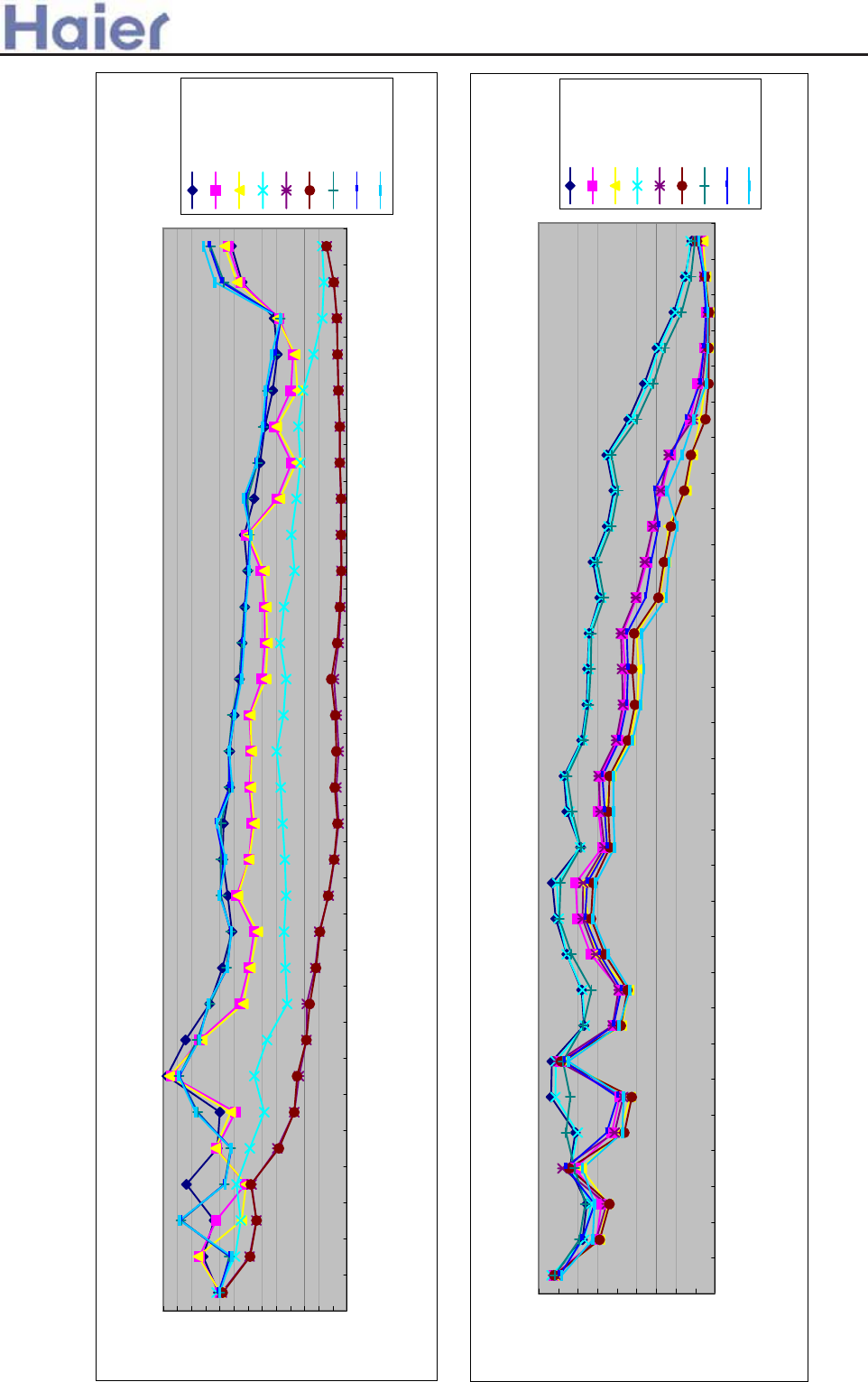
>a__WcU[S^<[c>a`V[e[a`Wc
48
1/3 octave band noise level-AU362AHERA
5
10
15
20
25
30
35
40
45
50
55
60
65
70
25.0
31.5
40.0
50.0
63.0
80.0
100.0
125.0
160.0
200.0
250.0
315.0
400.0
500.0
630.0
800.0
1000.0
1250.0
1600.0
2000.0
2500.0
3150.0
4000.0
5000.0
6300.0
8000.0
10000.0
12500.0
16000.0
20000.0
third octave band frequency Hz
sound pressure level DB
cooling high
cooling med
cooling low
fan high
fan med
fan low
heating high
heating med
heating low
1/3 octave band noise level-AB362ACERA
7.0
12.0
17.0
22.0
27.0
32.0
37.0
42.0
47.0
52.0
25.0
31.5
40.0
50.0
63.0
80.0
100.0
125.0
160.0
200.0
250.0
315.0
400.0
500.0
630.0
800.0
1000.0
1250.0
1600.0
2000.0
2500.0
3150.0
4000.0
5000.0
6300.0
8000.0
10000.0
12500.0
16000.0
20000.0
third octave band frequency Hz
Sound pressure level DB
cooling high
cooling med
cooling low
fan high
fan med
fan low
heating high
heating med
heating low
-207-
>a__WcU[S^<[c>a`V[e[a`Wc
Noise level-AC362AFERA
15
19
23
27
31
35
39
43
47
51
55
59
63
25
31.5
40
50
63
80
100
125
160
200
250
315
400
500
630
800
1000
1250
1600
2000
2500
3150
4000
5000
6300
8000
10000
12500
160000
20000
Third octave band frequency Hz
Sound pressure level DB
heating low
heating middle
heating high
cooling low
cooling middle
cooling high
fan low
fan middle
fan high
-208-
>a__WcU[S^<[c>a`V[e[a`Wc
1/3 octave band noise level-AB182ACEAA
8.0
13.0
18.0
23.0
28.0
33.0
38.0
43.0
48.0
53.0
25.0
31.5
40.0
50.0
63.0
80.0
100.0
125.0
160.0
200.0
250.0
315.0
400.0
500.0
630.0
800.0
1000.0
1250.0
1600.0
2000.0
2500.0
3150.0
4000.0
5000.0
6300.0
8000.0
10000.0
12500.0
16000.0
20000.0
third octave band frequency Hz
Sound pressure level DB
cooling high
cooling med
cooling low
fan high
fan med
fan low
heating high
heating med
heating low
1/3 octave band noise level-AC182ACEAA
16.0
21.0
26.0
31.0
36.0
41.0
46.0
51.0
56.0
25.0
31.5
40.0
50.0
63.0
80.0
100.0
125.0
160.0
200.0
250.0
315.0
400.0
500.0
630.0
800.0
1000.0
1250.0
1600.0
2000.0
2500.0
3150.0
4000.0
5000.0
6300.0
8000.0
10000.0
12500.0
16000.0
20000.0
third octave band frequency Hz
Sound pressure level DB
cooling high
cooling med
cooling low
fan high
fan med
fan low
heating high
heating med
heating low
-209-
>a__WcU[S^<[c>a`V[e[a`Wc
1/3 octave band noise level-AU182AEEAA
4
9
14
19
24
29
34
39
44
49
54
59
64
69
25.0
31.5
40.0
50.0
63.0
80.0
100.0
125.0
160.0
200.0
250.0
315.0
400.0
500.0
630.0
800.0
1000.0
1250.0
1600.0
2000.0
2500.0
3150.0
4000.0
5000.0
6300.0
8000.0
10000.0
12500.0
16000.0
20000.0
third octave band frequency Hz
sound pressure level DB
cooling super high
cooling high
cooling med
cooling low
fan super high
fan high
fan med
fan low
heating super high
heating high
heating med
heating low
1/3 octave band noise level-AD182ALEAA
8.0
13.0
18.0
23.0
28.0
33.0
38.0
43.0
48.0
53.0
25.0
31.5
40.0
50.0
63.0
80.0
100.0
125.0
160.0
200.0
250.0
315.0
400.0
500.0
630.0
800.0
1000.0
1250.0
1600.0
2000.0
2500.0
3150.0
4000.0
5000.0
6300.0
8000.0
10000.0
12500.0
16000.0
20000.0
third octave band frequency Hz
Sound pressure level DB
cooling super high
cooling high
cooling med
cooling low
fan super high
fan high
fan med
fan low
heating super high
heating high
heating med
heating low
--210-
>a__WcU[S^<[c>a`V[e[a`Wc
Noise level-AD282AHEAA
15
18
21
24
27
30
33
36
39
42
45
48
51
54
57
60
25
31.5
40
50
63
80
100
125
160
200
250
315
400
500
630
800
1000
1250
1600
2000
2500
3150
4000
5000
6300
8000
10000
12500
160000
20000
Third octave band frequency Hz
Sound pressure level DB
heating low
heating middle
heating high
cooling low
cooling middle
cooling high
fan low
fan middle
fan high
Noise level-AD282AMEAA
7
10
13
16
19
22
25
28
31
34
37
40
43
46
49
52
55
25
31.5
40
50
63
80
100
125
160
200
250
315
400
500
630
800
1000
1250
1600
2000
2500
3150
4000
5000
6300
8000
10000
12500
160000
20000
Third octave band frequency Hz
Sound pressure level DB
heating low
heating middle
heating high
super heating high
cooling low
cooling middle
cooling high
super cooling high
fan low
fan middle
fan high
super fan high
-211-
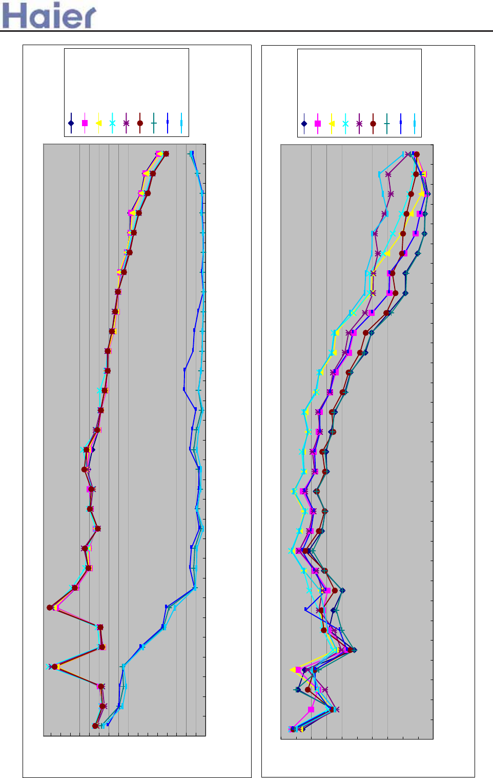
>a__WcU[S^<[c>a`V[e[a`Wc
Noise level-AU28NAHEAA
7
11
15
19
23
27
31
35
39
43
47
51
55
59
63
67
71
25
31.5
40
50
63
80
100
125
160
200
250
315
400
500
630
800
1000
1250
1600
2000
2500
3150
4000
5000
6300
8000
10000
12500
160000
20000
Third octave band frequency Hz
Sound pressure level DB
heating low
heating middle
heating high
cooling low
cooling middle
cooling high
fan low
fan middle
fan high
Noise level-AC282AFEAA
8
12
16
20
24
28
32
36
40
44
48
25
31.5
40
50
63
80
100
125
160
200
250
315
400
500
630
800
1000
1250
1600
2000
2500
3150
4000
5000
6300
8000
10000
12500
160000
20000
Third octave band frequency Hz
Sound pressure level DB
heating low
heating middle
heating high
cooling low
cooling middle
cooling high
fan low
fan middle
fan high
-212-
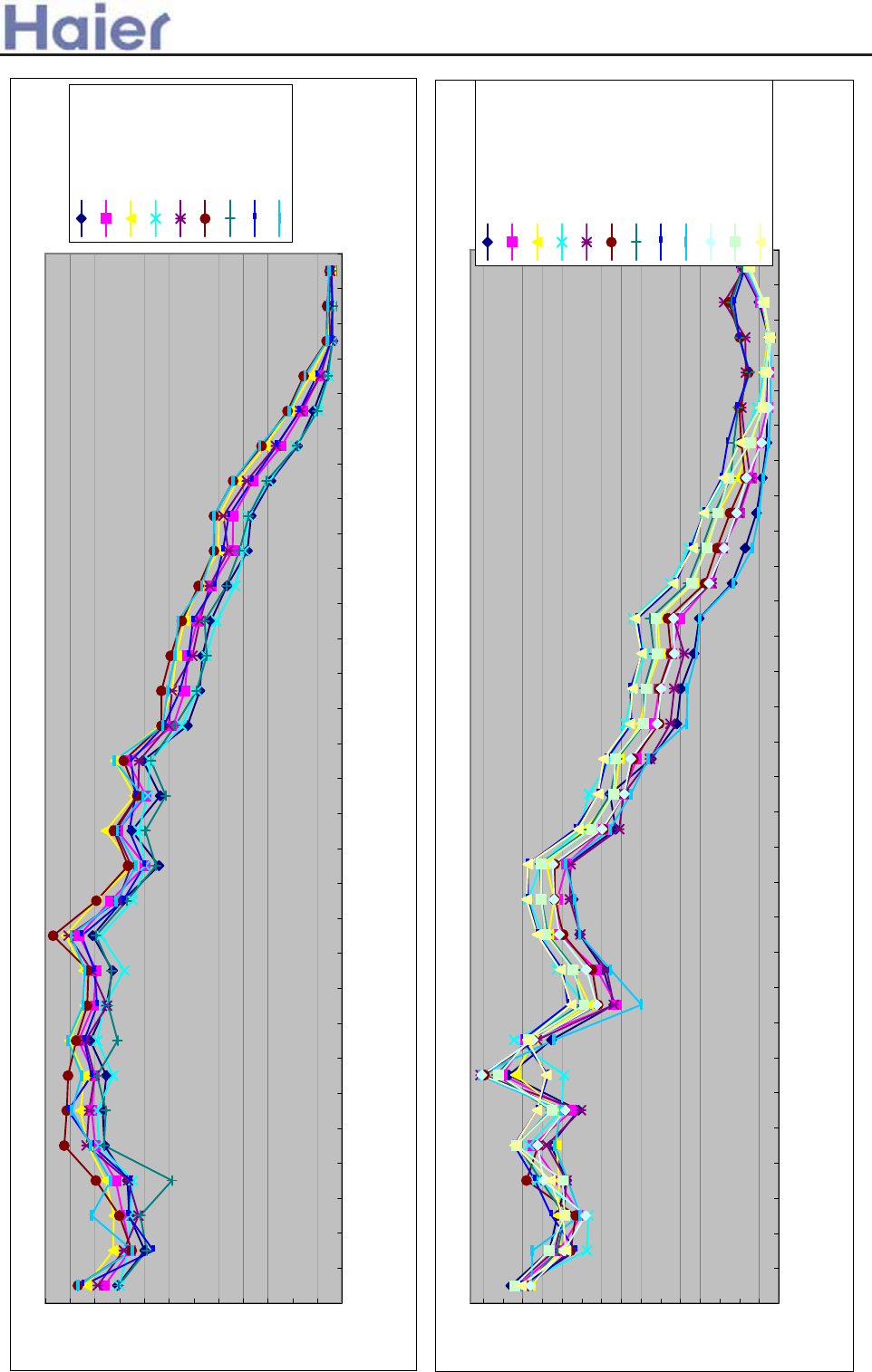
>a__WcU[S^<[c>a`V[e[a`Wc
Noise level-AD362AHEAA
15
19
23
27
31
35
39
43
47
51
55
59
63
25
31.5
40
50
63
80
100
125
160
200
250
315
400
500
630
800
1000
1250
1600
2000
2500
3150
4000
5000
6300
8000
10000
12500
160000
20000
Third octave band frequency Hz
Sound pressure level DB
heating low
heating middle
heating high
cooling low
cooling middle
cooling high
fan low
fan middle
fan high
Noise level-AD362AMEAA
8
11
14
17
20
23
26
29
32
35
38
41
44
47
50
53
25
31.5
40
50
63
80
100
125
160
200
250
315
400
500
630
800
1000
1250
1600
2000
2500
3150
4000
5000
6300
8000
10000
12500
160000
20000
Third octave band frequency Hz
Sound pressure level DB
heating low
heating middle
heating high
super heating high
cooling low
cooling middle
cooling high
super cooling high
fan low
fan middle
fan high
super fan high
-213-
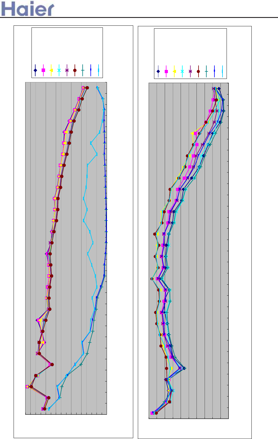
>a__WcU[S^<[c>a`V[e[a`Wc
Noise level-AU36NAIEAA
6
10
14
18
22
26
30
34
38
42
46
50
54
58
62
66
70
25
31.5
40
50
63
80
100
125
160
200
250
315
400
500
630
800
1000
1250
1600
2000
2500
3150
4000
5000
6300
8000
10000
12500
160000
20000
Third octave band frequency Hz
Sound pressure level DB
heating low
heating middle
heating high
cooling low
cooling middle
cooling high
fan low
fan middle
fan high
Noise level-AC362AFEAA
8
12
16
20
24
28
32
36
40
44
48
25
31.5
40
50
63
80
100
125
160
200
250
315
400
500
630
800
1000
1250
1600
2000
2500
3150
4000
5000
6300
8000
10000
12500
160000
20000
Third octave band frequency Hz
Sound pressure level D
B
heating low
heating middle
heating high
cooling low
cooling middle
cooling high
fan low
fan middle
fan high
-214-
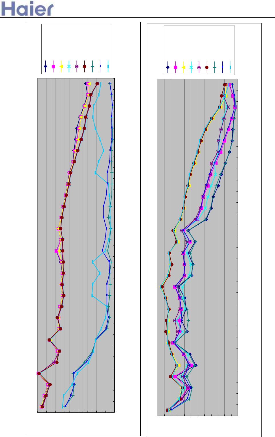
>a__WcU[S^<[c>a`V[e[a`Wc
30
Noise level-AU42NALEAA
6
10
14
18
22
26
30
34
38
42
46
50
54
58
62
66
70
74
25
31.5
40
50
63
80
100
125
160
200
250
315
400
500
630
800
1000
1250
1600
2000
2500
3150
4000
5000
6300
8000
10000
12500
160000
20000
Third octave band frequency Hz
Sound pressure level DB
heating low
heating middle
heating high
cooling low
cooling middle
cooling high
fan low
fan middle
fan high
Noise level-AP422ACEAA
8
12
16
20
24
28
32
36
40
44
48
52
56
25
31.5
40
50
63
80
100
125
160
200
250
315
400
500
630
800
1000
1250
1600
2000
2500
3150
4000
5000
6300
8000
10000
12500
160000
20000
Third octave band frequency Hz
Sound pressure level DB
heating low
heating middle
heating high
cooling low
cooling middle
cooling high
fan low
fan middle
fan high
-215-
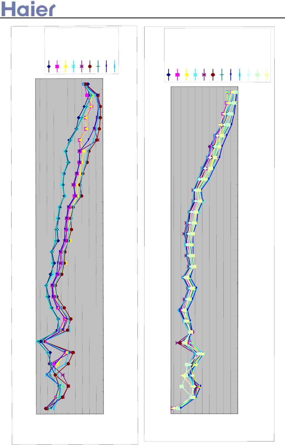
>a__WcU[S^<[c>a`V[e[a`Wc
1/3 octave band noise level-AB482ACEAA
8.0
13.0
18.0
23.0
28.0
33.0
38.0
43.0
48.0
53.0
25.0
31.5
40.0
50.0
63.0
80.0
100.0
125.0
160.0
200.0
250.0
315.0
400.0
500.0
630.0
800.0
1000.0
1250.0
1600.0
2000.0
2500.0
3150.0
4000.0
5000.0
6300.0
8000.0
10000.0
12500.0
16000.0
20000.0
third octave band frequency Hz
Sound pressure level DB
cooling high
cooling med
cooling low
fan high
fan med
fan low
heating high
heating med
heating low
25
1/3 octave band noise level-AC482ACEAA
9.0
14.0
19.0
24.0
29.0
34.0
39.0
44.0
49.0
54.0
25.0
31.5
40.0
50.0
63.0
80.0
100.0
125.0
160.0
200.0
250.0
315.0
400.0
500.0
630.0
800.0
1000.0
1250.0
1600.0
2000.0
2500.0
3150.0
4000.0
5000.0
6300.0
8000.0
10000.0
12500.0
16000.0
20000.0
third octave band frequency Hz
Sound pressure level DB
cooling super high
cooling high
cooling med
cooling low
fan super high
fan high
fan med
fan low
heating super high
heating high
heating med
heating low
-216-
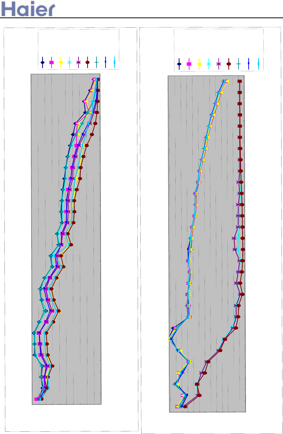
>a__WcU[S^<[c>a`V[e[a`Wc
1/3 octave band noise level-AU48NAIEAA
4
9
14
19
24
29
34
39
44
49
54
59
64
69
25.0
31.5
40.0
50.0
63.0
80.0
100.0
125.0
160.0
200.0
250.0
315.0
400.0
500.0
630.0
800.0
1000.0
1250.0
1600.0
2000.0
2500.0
3150.0
4000.0
5000.0
6300.0
8000.0
10000.0
12500.0
16000.0
20000.0
third octave band frequency Hz
sound pressure level DB
cooling high
cooling med
cooling low
fan high
fan med
fan low
heating high
heating med
heating low
1/3 octave band noise level-AD482AHEAA
8.0
13.0
18.0
23.0
28.0
33.0
38.0
43.0
48.0
53.0
58.0
25.0
31.5
40.0
50.0
63.0
80.0
100.0
125.0
160.0
200.0
250.0
315.0
400.0
500.0
630.0
800.0
1000.0
1250.0
1600.0
2000.0
2500.0
3150.0
4000.0
5000.0
6300.0
8000.0
10000.0
12500.0
16000.0
20000.0
third octave band frequency Hz
Sound pressure level DB
cooling high
cooling med
cooling low
fan high
fan med
fan low
heating high
heating med
heating low
-217-
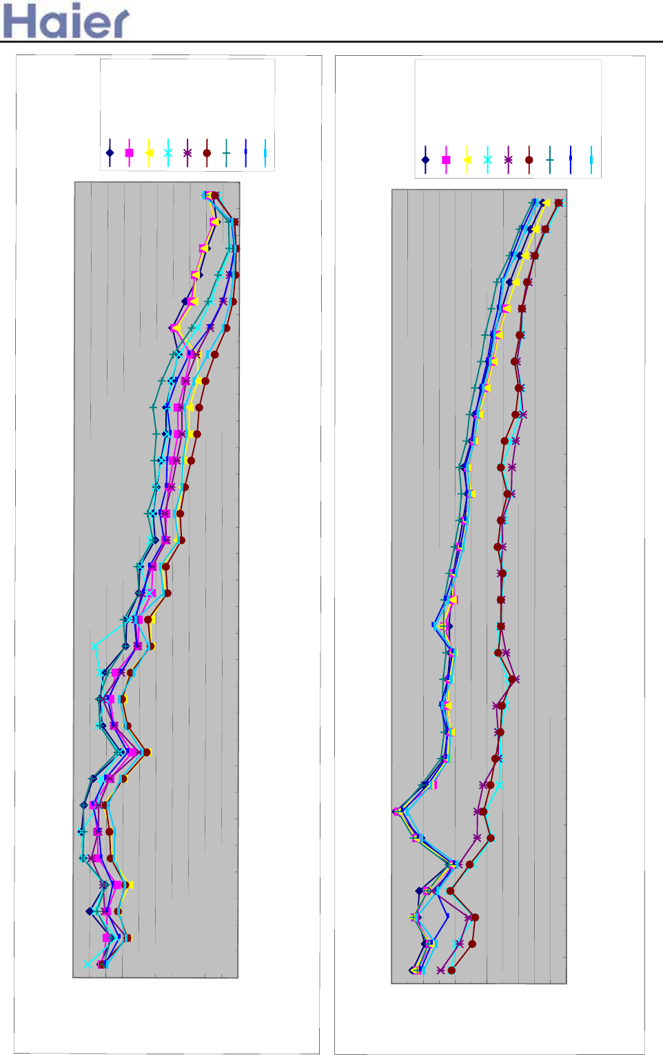
>a__WcU[S^<[c>a`V[e[a`Wc
29
1/3 octave band noise level-AD602AHEAA
8.0
13.0
18.0
23.0
28.0
33.0
38.0
43.0
48.0
53.0
58.0
25.0
31.5
40.0
50.0
63.0
80.0
100.0
125.0
160.0
200.0
250.0
315.0
400.0
500.0
630.0
800.0
1000.0
1250.0
1600.0
2000.0
2500.0
3150.0
4000.0
5000.0
6300.0
8000.0
10000.0
12500.0
16000.0
20000.0
Sound pressure level DB
cooling high
cooling med
cooling low
fan high
fan med
fan low
heating high
heating med
heating low
24
15.0
20.0
25.0
30.0
35.0
40.0
45.0
50.0
55.0
60.0
65.0
70.0
25.0
31.5
40.0
50.0
63.0
80.0
100.0
125.0
160.0
200.0
250.0
315.0
400.0
500.0
630.0
800.0
1000.0
1250.0
1600.0
2000.0
2500.0
3150.0
4000.0
5000.0
6300.0
8000.0
10000.0
12500.0
16000.0
20000.0
third octave band frequency Hz
sound pressure level DB
cooling high
cooling med
cooling low
fan high
fan med
fan low
heating high
heating med
heating low
1/3 octave band noise level-
AU60NAIEAA
third octave band frequency Hz
-218-
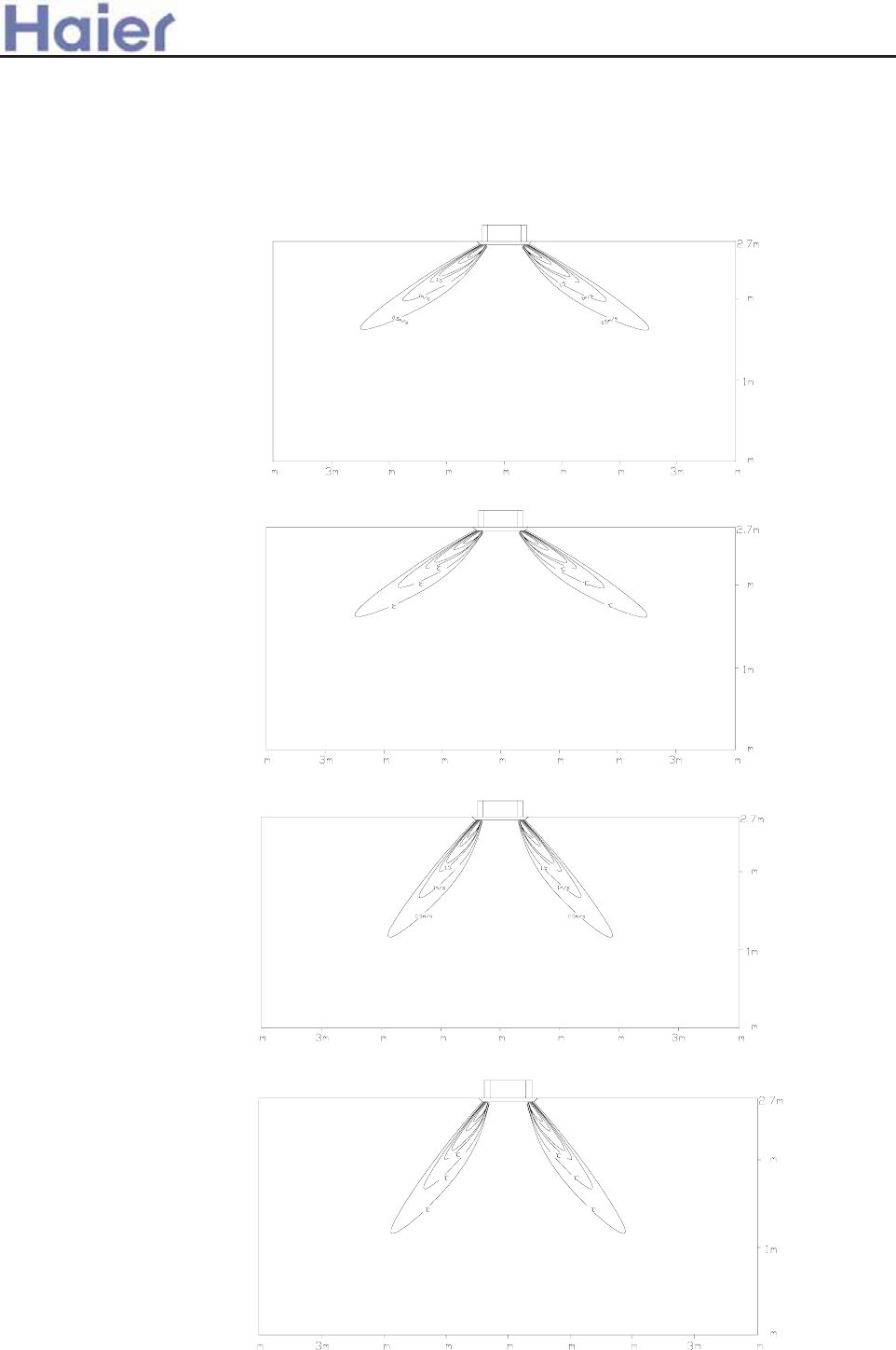
>a__WcU[S^<[c>a`V[e[a`Wc
1) Cassette type (AB182*****)
PV
PV
Air Velocity Distribution
Cooling
Blowy angle:40
Temperature Distribution
Cooling
Blowy angle:40
a. Cooling / Air Velocity Distribution
b. Cooling / Temperature Distribution
13. Air velocity distribution
PV
PV
Heating
Blowy angle:70
Air velocity Distribution
c. Heating / Air Velocity Distribution
d. Heating / Temperature Distribution
Temperature Distribution
Heating
Blowy angle:70
18000BTU/h indoor uni
--219-
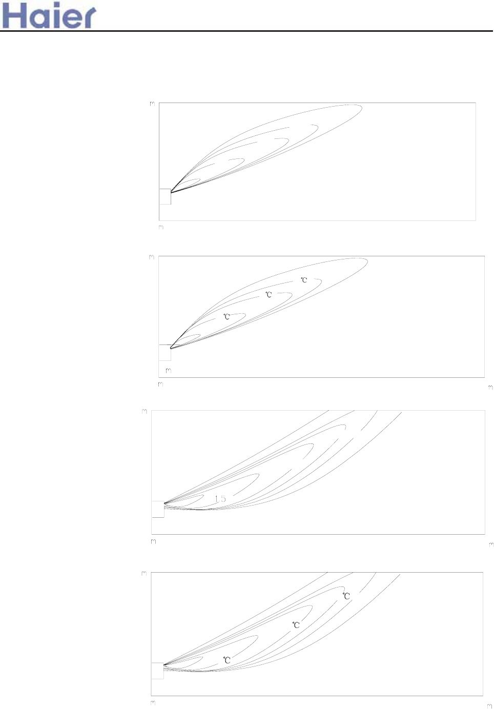
>a__WcU[S^<[c>a`V[e[a`Wc
a) Grounding
Air Velocity Distribution
Cooling
Blowy angle:25
a. Cooling / Air Velocity Distribution
0
1.5m/s
1.0m/s
0.5m/s
2)Convertible type (AC182*****)
Temperature Distribution
Cooling
Blowy angle:25
b. Cooling / Temperature Distribution
Heating
Blowy angle:5
Air velocity Distribution
c. Heating / Air Velocity Distribution
PV
PV
PV
d. Heating / Temperature Distribution
Temperature Distribution
Heating
Blowy angle:5
-220-
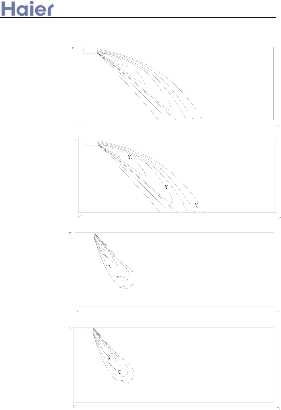
>a__WcU[S^<[c>a`V[e[a`Wc
Air Velocity Distribution
Cooling
Blowy angle:25
Temperature Distribution
Cooling
Blowy angle:25
PV
PV
PV
b) Ceiling
a. Cooling / Air Velocity Distribution
b. Cooling / Temperature Distribution
Heating
Blowy angle:65
Air velocity Distribution
Temperature Distribution
Heating
Blowy angle:65
PV
c. Heating / Air Velocity Distribution
d. Heating / Temperature Distribution
-221-
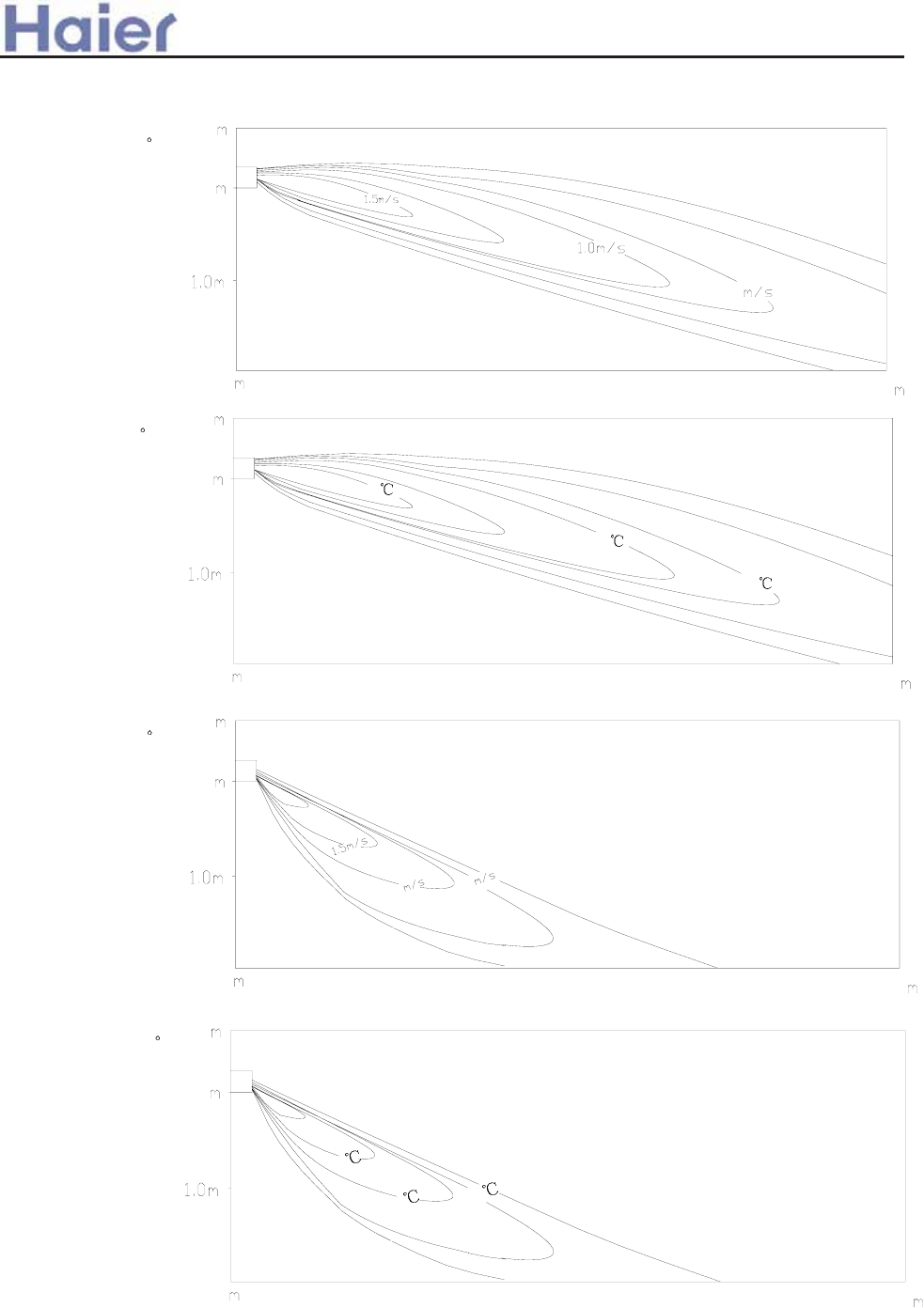
>a__WcU[S^<[c>a`V[e[a`Wc
3)Duct type (AD182*****)
air discharge angle
cooling
cooling
air discharge angle 5
Air Velocity distribution
Temperature distribution
heating
air discharge angle 45
Air Velocity distribution
heating
air discharge angle 45
Temperature distribution
-222-

>a__WcU[S^<[c>a`V[e[a`Wc
24000~28000BTU/h indoor units
Model: AC282*****
Air Velocity Distribution
Cooling
Blowy angle:25
Temperature Distribution
Cooling
Blowy angle:25
a. Cooling / Air Velocity Distribution
b. Cooling / Temperature Distribution
1.5m/s
1.0m/s
0.5m/s
Model: AB282*****
Air Velocity Distribution
Cooling
Blowy angle:40
a. Cooling / Air Velocity Distribution
PV
PV
Temperature Distribu
tion
Cooling
Blowy angle:40
b. Cooling / Temperature Distribution
-223-
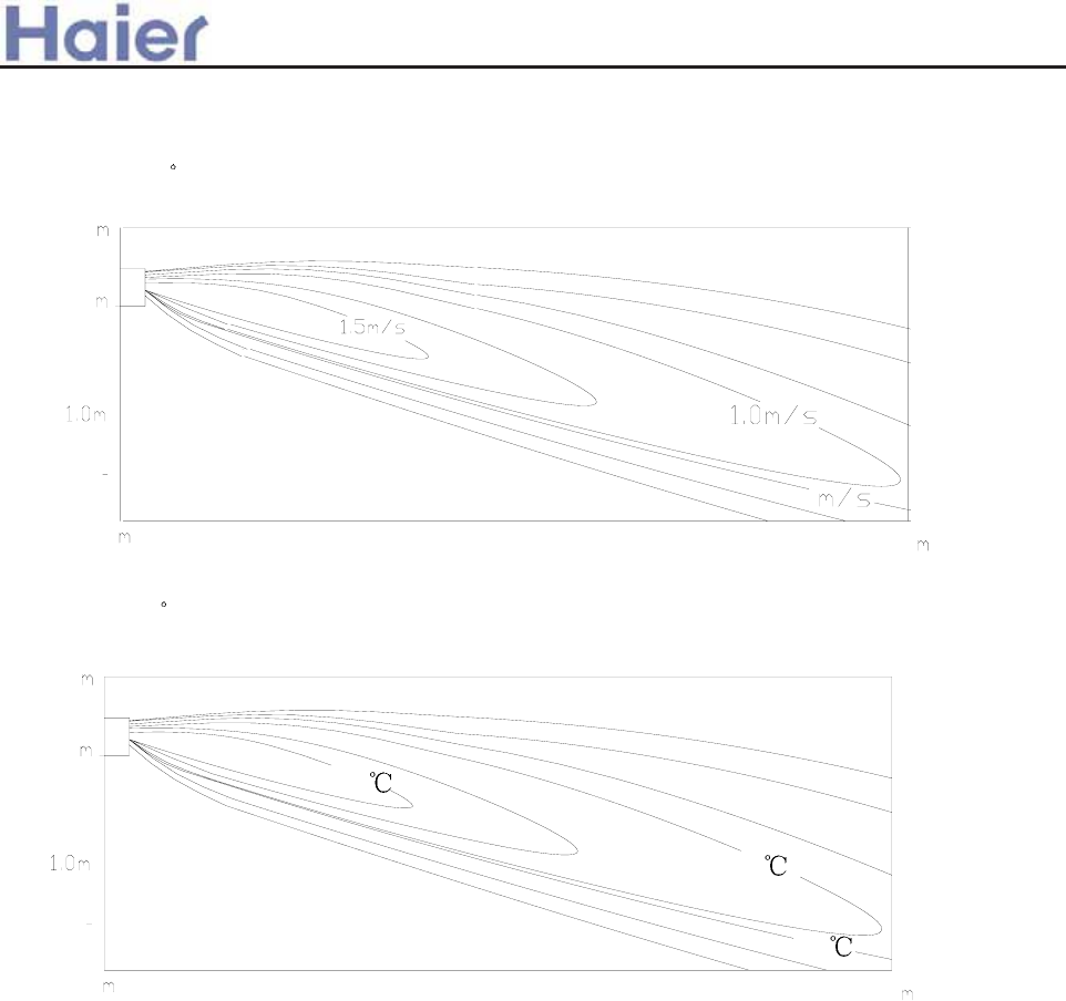
>a__WcU[S^<[c>a`V[e[a`Wc
AD282*****
cooling
cooling
air discharge angle 5
Air Velocity distribution
Temperature distribution
air discharge angle 5
-224-
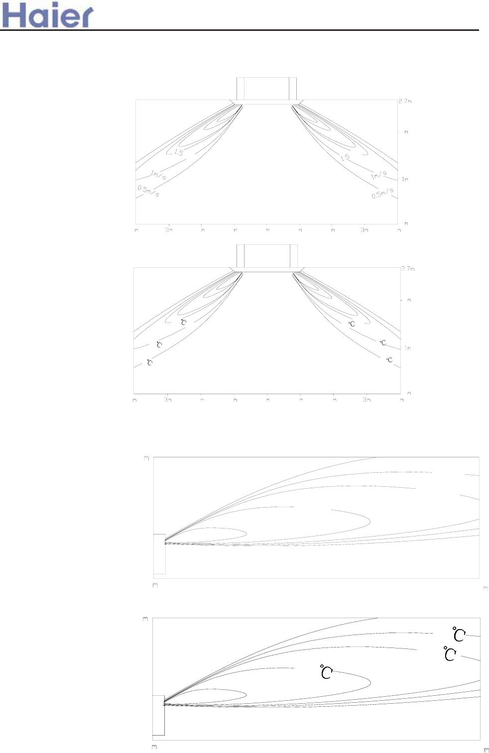
>a__WcU[S^<[c>a`V[e[a`Wc
36000~42000BTU/h indoor units
1)AB362*****
Air Velocity Distribution
Cooling
Blowy angle:40
Temperature Distribution
Cooling
Blowy angle:40
a. Cooling / Air Velocity Distribution
b. Cooling / Temperature Distribution
PV
PV
2) AC362*****
Air Velocity Distribution
Cooling
Blowy angle:25
a. Cooling / Air Velocity Distribution
Temperature Distribution
Cooling
Blowy angle:25
b. Cooling / Temperature Distribution
-225-

Ahh]f\ao
If^iYi]\ [gfkigdd]ij?
WP2H<6
WP2H:5
WP2H9>
Uai]\ [gfkigdd]ij?
WP2E67
C]fkiYd [gfkigdd]i?
WCX2A556
U]]cdp kae]i?
WCQ2A556
2Cgfkigdd]ij
CRZVb >_]]VbTZR\ <Zb >_^UZdZ_^Vb
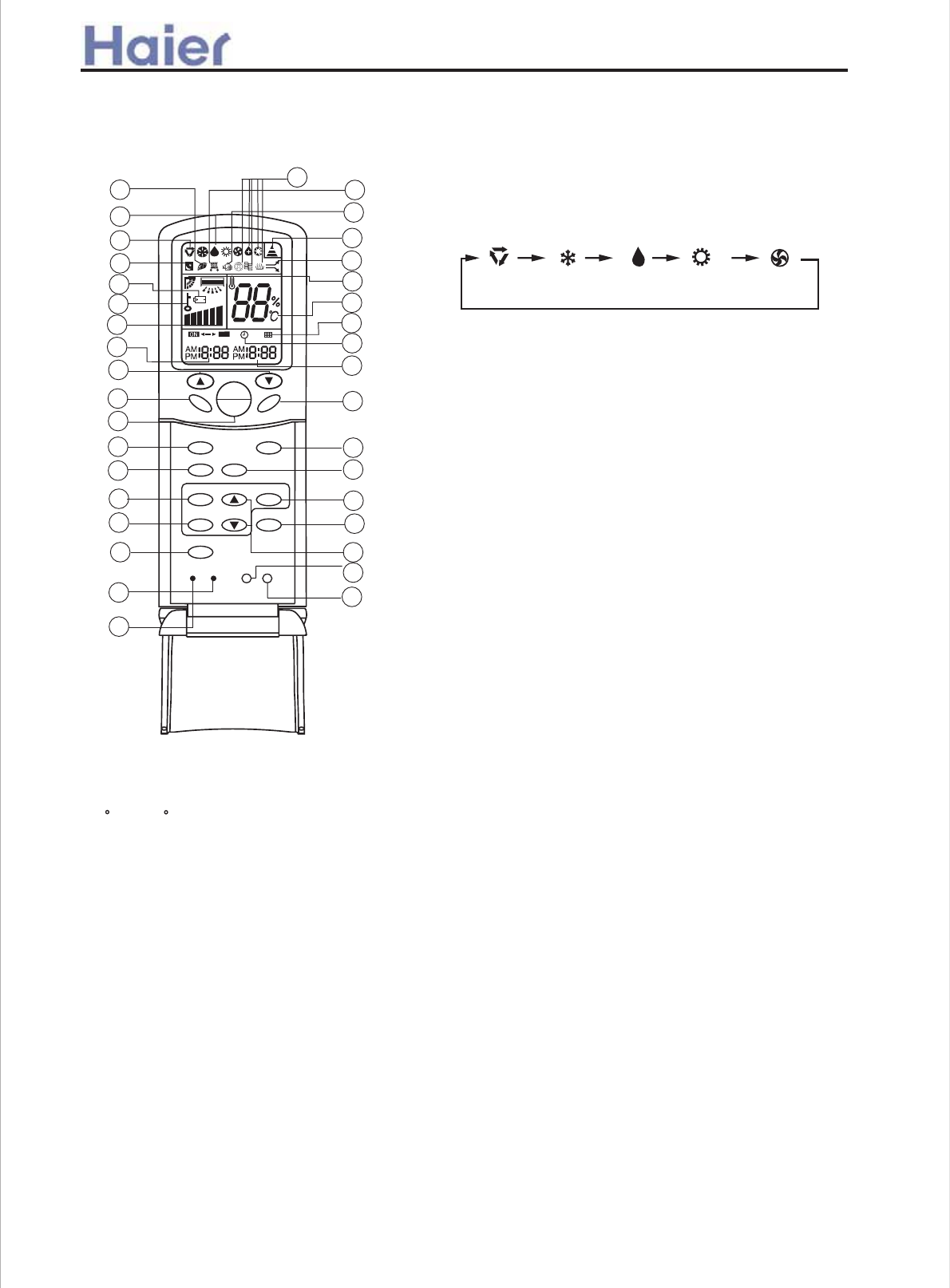
Cgee]i[aYd Aai Cgf\akagf]i
*-|=><=}GD 7edd_^
IcUT d_ cU\USd =><= _b GD;H _`UbQdY_^|
}|
}}
~|
}/
~}
;F:G=
=><=}GD
H>B:F
G:H
;>AH:F
76
=:6AH=
F:G:H AD8@
GA::E
;6C
H:BE
DC
D;;
GK>C<
BD9:
8AD8@
8D9: A><=H
NFF
A
S
R
N
|
}
~
*
,
-
/
|{
||
|+
|~
+
.
|,
|-
~{
~*
~+
~~ }~
}*
}+
},
}-
}.
}{
|}
|*
63RELO Q]kkaf_ Blkkgf
vIcUT d_ cUd dU]`UbQdebU|GUddY^W bQ^WUc3
*/8d_,~8w
>^ I`}9_g^ Ve^SdY_^zV_b S_^db_\\Y^W e` Q^T
T_g^ VY\dUb|
+|GK>C< 7edd_^
>V i_e `bUcc dXYc Redd_^ _^SUzQed_ cgY^W gY\\
RU QSdYfQdUT|
>V i_e `bUcc dXYc Redd_^ QWQY^zdXU \_efUb gY\\
VYh Y^ dXU `bUcU^d `_cYdY_^|
,|E_gUb DC}D;; 7edd_^
IcUT V_b e^Yd cdQbd Q^T cd_`
6VdUb `_gUb _^zdXU A89 _V bU]_dU S_^db_\\Ub
gY\\ TYc`\Qi dXU `bUfY_ec _`UbQdY_^ cdQdU vUhSU`d
V_b H>B:FzGA::E Q^T GK>C< cdQdUw|
-|D`UbQdY_^ BD9:
IcUT d_ cU\USd _`UbQdY_^ ]_TU|
:fUbi dY]U i_e `bUcc BD9: Redd_^z_`UbQdY_^ ]_TU
SXQ^WUc QSS_bTY^W d_ V_\\_gY^W cUaeU^SU3
.|=:6AH= 7edd_^
IcUT d_ cUd XUQ\dX ]_TUzYV dXU e^Yd XQc dXU ^UWQdYfU Y_^
Ve^SdY_^ Q^T _hiWU^ RQb Ve^SdY_^|
6IHD ;6C
=:6H
8DDA 9FM
/|8AD8@ 7edd_^
IcUT d_ cUd S_bbUSd dY]U|
vC_dU3 YV dY]U _V H>B:F DC Yc dXU cQ]U Qc H>B:F
D;;zH>B:F DC}D;; SQ^^_d RU cUdw
*~|F:G:H 7edd_^
EbUcc dXYc Redd_^ Ri ecY^W Q cXQb` QbdYS\U d_ bUce]U
dXU S_bbUSd _`UbQdY_^ _V dXU bU]_dU S_^db_\\Ub Y^ SQcU
_V ^UUTzY|U|V_b UhQ]`\U Y^ SQcU _V ]Q\Ve^SdY_^c TeU
d_ U\USdb_]QW^UdYS ^_YcU|
*0|GA::E 7edd_^
vHXU S\_S[ ]ecd RU S_bbUSdUT RUV_bU cUddY^W c\UU`
Ve^SdY_^wIcUT d_ cUd c\UU` ]_TU|
*,|I` Q^T T_g^ 7edd_^
IcUT d_ cUd H>B:F Q^T 8AD8@ e` _b T_g^|
1|;>AH:F 7edd_^
IcUT d_ cUd e`}T_g^ Ve^SdY_^ _V VY\dUb|
MNRE? *|8__\Y^W _^\i QYb S_^TYdY_^Ub T_Uc ^_d XQfU dXU TYc`\Qic Q^T Ve^SdY_^c bU\QdUT d_ XUQdY^W|
+|=><=}GD Redd_^
HXYc Redd_^ Yc QSdYfQdUT Y^ 8__\Y^W}=UQdY^W ]_TUzdXU VQ^ c`UUT Yc Y^ 6IHD ]_TU QVdUb
`bUccY^W Yd Q^T tXYWX Ve^Sd_^tgY\\ RU SQ^SU\\UT Qed_]QdYSQ\\i QVdUb *. ]Y^edUc be^^Y^W|
**|AD8@ 7edd_^
IcUT d_ \_S[ _`UbQdY_^ Redd_^ Q^T A89 TYc`\Qi
S_^dU^dc3 Ri `bUccY^W dXYc Redd_^z_dXUb Redd_^c S_]Uc
_ed _V Ve^SdY_^ Q^T \_S[ cdQdU TYc`\Qi Q``UQbc4 YV i_e `bUcc
Yd QWQY^z\_S[ cdQdU gY\\ RU ^_ ]_bU QSdYfU Q^T \_S[ cdQdU
TYc`\Qi gY\\ TYcQ``UQb|
0|8AD8@ 7edd_^
IcUT d_ cU\USd H>B:F DCzH>B:F D;;|
2|8D9: 7edd_^
IcUT d_ cU\USd S_TU 6 _b 7zV_b dXU e^Ydc UhSU`d
dXQd gU bUS_]]U^T Uc`USYQ\\izdXU S_TU Yc 6|
|.
*+|A><=H 7edd_^
IcUT d_ \YWXd dXU S_^db_\ `Q^U\ v_^\i V_b SQRY^Ud e^Ydw
*.|G:H 7edd_^
IcUT d_ S_^VYb] H>B:F Q^T 8AD8@ cUddY^Wc|
*/|;F:G= 7edd_^
IcUT d_ cUd VbUcX ]_TUzdXU e^Yd gY\\ TbQg Y^ VbUcX QYb|
|/
~,
636 If^iYi]\ [gfkigdd]i WP2H<6
6 If^iYi]\ [gfkigdd]i
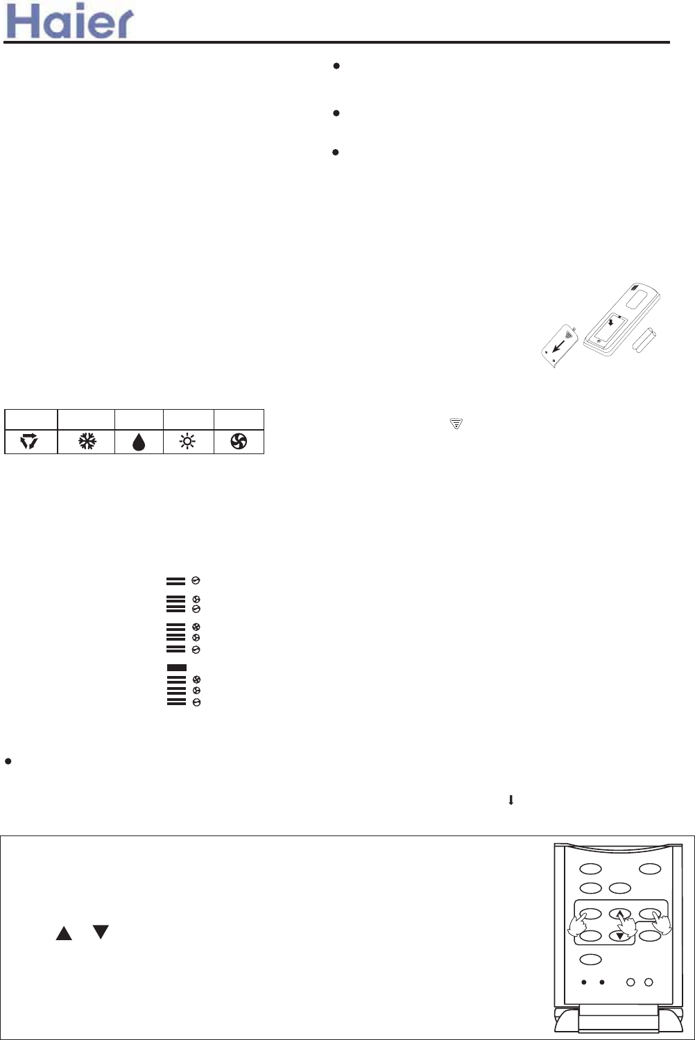
Cgee]i[aYd Aai Cgf\akagf]i
HXU TYcdQ^SU RUdgUU^ dXU bU]_dU S_^db_\\Ub Q^T
dXU bUSUYfUb cX_e\T RU ]Qh 0] Q^T dXUbU cX_e\T RU
Cdg[c Q]k
9Yc`\Qic gXU^ XUQ\dXi be^ Ve^SdY_^ Yc cUd|
++|H:BE:F6HIF: 9Yc`\Qi
,-|AD8@ GdQdU 9Yc`\Qi
,,|76HH:FM :^UbWi 9Yc`\Qi
C_dYVi dXU ecUb gXU^ Yd Yc dY]U d_ SXQ^WU
dXU RQddUbYUc|
+-|=><=}GD 9Yc`\Qi
+.|G><C6A G:C9>C< 9Yc`\Qi
+/|;F:G= 6>F 9Yc`\Qi
+0|:A:8HF>86A =:6H>C< 9Yc`\Qi
+2|=:6AH= 9Yc`\Qi
,+|GA::E GdQdU 9Yc`\Qi
,*|D`UbQdY_^ BD9: 9Yc`\Qi
6IHD FIC 8DDA FIC 9FM FIC =:6H FIC ;6C FIC
,.|;6C GE::9 9Yc`\Qi
+,|6IHD GK>C< 9Yc`\Qi
*2|H>B:F D;; 9Yc`\Qi
+*|;>AH:F 9Yc`\Qi
,/|H>B:F DC 9Yc`\Qi
KXU^ e^Yd Yc cdQbdUT V_b dXU VYbcd dY]U Q^T QVdUb bU`\QSY^W RQddUbYUc Y^ bU]_dU
S_^db_\\UbzS\_S[ cX_e\T RU QTZecdUT Qc V_\\_gc3
*|EbUcc 8AD8@ Redd_^zS\_S[ Y^TYSQdY_^ _V t6B t_b tEB tV\QcXUc|
+|EbUcc _b d_ cUd S_bbUSd dY]U|:QSX `bUcc gY\\ Y^SbUQcU _b TUSbUQcU
* ]Y^|>V dXU Redd_^ Yc [U`d `bUccUTzdY]U gY\\ Y^SbUQcU _b TUSbUQcU aeYS[\i|
,|6VdUb dY]U cUddY^W Yc S_^VYb]UTz`bUcc tG:Ht3 6B _b EB cd_` V\QcXY^Wz
gXY\U S\_S[ cdQbdc g_b[Y^W|
C_dU36B ]UQ^c ]_b^Y^W Q^T EB ]UQ^c QVdUb^__^|
KXU^ _`UbQdY^W dXU bU]_dU S_^db_\\Ub Y^ Q^
QbUQ gXUbU U\USdb_^YSQ\\i S_^db_\\UT \YWXdc QbU
Y^cdQ\\UT _b gYbU\Ucc XQ^TcUdc QbU ecUTz`\UQcU ]_fU
S\_cUb d_ dXU Y^T__b e^Yd Qc dXU Ve^SdY_^ _V dXU bU]_dU
S_^db_\\Ub ]YWXd RU QVVUSdUT Ri cYW^Q\c U]YddUT
Ri dXU QR_fU ]U^dY_^UT UaeY`]U^dc|
4GFB
AD
B>9
=>
6IHD
P]egk] Cgfkigdd]i, Nh]iYkagf
KXU^ Y^ ecUzTYbUSd cYW^Q\ dbQ^c]YccY_^
XUQT d_ dXU bUSUYfUb `\QSUT _^ dXU Y^T__b
e^Yd
^_ _RcdQS\U RUdgUU^ dXU]|
9_ ^_d dXb_g dXU bU]_dU S_^db_\\Ub4 `bUfU^d Yd
Vb_] RUY^W TQ]QWUT|
*1|;6C 7edd_^
IcUT d_ cU\USd VQ^ c`UUT3ADKzB>9z=><=z6IHD|
+~|8AD8@ 9Yc`\Qi
,~|9:=IB>9>;>86H>DC 9Yc`\Qi
+1|G_]U _dXUb Redd_^c
6\\ dXUcU Ve^SdY_^c QbU ^_d QfQY\QR\U ^_g|
;F:G=
=><=}GD
H>B:F
G:H
;>AH:F
=:6AH=
F:G:H AD8@
GA::EBD9:
8AD8@
8D9: A><=H
~
}
|
8_^VYb]QdY_^ Y^TYSQd_b
>V ^_ Y^TYSQdY_^ Yc TYc`\QiUT QVdUb `bUcc DC}D;; Redd_^z
bU\_QT dXU RQddUbYUc|
8QedY_^3
>V dXU bU]_dU S_^db_\\Ub T_Uc ^_d _`UbQdU Qc TUcYW^UT
QVdUb VYddY^W ^Ug RQddUbYUc _V dXU cQ]U di`Uz`bUcc
dXU FUcUd Redd_^ v]Qb[UT wgYdX Q `_Y^dUT QbdYS\U|
KgY\af_ k`] ZYkk]ip
:^cebU dXQd RQddUbYUc QbU S_bbUSd\i `\QSUT Y^ dXU S_]
{`Qbd]U^d Qc bUaeYbUT V_b `_cYdYfU Q^T ^UWQdYfU dUb
{]Y^Q\c|
P]hdY[af_ k`] ZYkk]ip [gehYike]fk da\
HXU RQddUbi S_]`Qbd]U^d \YT Yc bUY^cdQ\\UT Y^ dXU
bUfUbcU cUaeU^SU|
DajhdYp i]ma]n
EbUcc dXU Redd_^ d_ cUU YV RQddUbYUc QbU `b_`Ub\i VYddUT|
>V ^_ TYc`\Qi Q``UQbczbUVYd dXU RQddUbYUc|
7QddUbi \_QTY^W
7QddUbi \_QTY^W
7QddUbYUc QbU VYddUT Qc V_\\_gc3
FU]_fU dXU RQddUbi S_]`Qbd]U^d \YT
G\YWXd\i `bUcc Q^T TYcU^WQWU dXU RQddUbi S_]`Qbd]U^d
\YT ]Qb[UT gYdX ttQ^T dXU^ X_\T dXU bU]_dU
S_^db_\\Ub Ri dXU e``Ub cUSdY_^ Q^T dXU^ bU]_fU
dXU RQddUbi S_]`Qbd]U^d \YT Ri `bUccY^W Y^ dXU TYbUSdY_^
_V dXU Qbb_g Qc cX_g^ Y^ dXU VYWebU QR_fU|
**
**
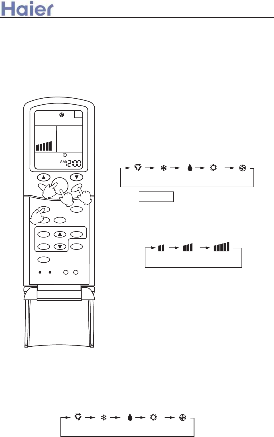
FYf Nh]iYkagf *|I^Yd cdQbd
EbUcc DC}D;; Redd_^ d_ cdQbd i_eb QYb S_^TYdY_^Ub|
EbUfY_ec _`UbQdY_^ cdQdec Q``UQbc _^ A89 vUhSU`d V_b
H>B:FzGA::EzQ^T GK>C< cUddY^Ww|
+|GU\USd _`UbQdY^W ]_TU
EbUcc BD9: Redd_^|6d UQSX `bUccz_`UbQdY_^ ]_TU
SXQ^WUc Qc V_\\_gc3
,|6TZecd VQ^ c`UUT
EbUcc ;6C Redd_^|6d UQSX `bUcczVQ^ c`UUT SXQ^WUc Qc
V_\\_gc3
6Yb S_^TYdY_^Ub gY\\ be^ Qd dXU cU\USdUT VQ^ c`UUT|
KXU^ Y^ 6IHD ]_TUze^Yd gY\\ QTZecd VQ^ c`UUT QSS_bTY^W
d_ b__] dU]`UbQdebU Qed_]QdYSQ\\i|
-|I^Yd cd_`
EbUcc DC}D;; Redd_^ d_ cd_` e^Yd|
HXU^ cU\USd ;6C
6R_ed ;6C ]_TU
KXU^ dXU QYb S_^TYdY_^Ub be^c Y^ ;6C ]_TUz
Yd Yc ^_d `_ccYR\U d_ cU\USd 6IHD ;6C _b d_
cUd dU]`UbQdebU|
6IHD ;6C=:6H8DDA 9FM
ADK B>9 =><=
C_dU3
>d Yc bUS_]]U^TUT dXQd dXU RQddUbYUc RU bU]_fUT Vb_] dXU S_]`Qbd]U^d YV dXU bU]_dU S_^db_\\Ub Yc ^_d
ecUT V_b Q^ UhdU^TUT `UbY_T|
HXU bU]_dU S_^db_\\Ub Yc `b_WbQ]]UT V_b Qed_]QdYS dUcd _V _`UbQdY_^ ]_TU QVdUb dXU RQddUbYUc QbU bU`\QSUT|
KXU^ dXU dUcd Yc S_^TeSdUTzQ\\ YS_^c gY\\ Q``UQb _^ dXU cSbUU^ Q^T dXU^ TYcQ``UQb YV dXU RQddUbYUc
QbU `b_`Ub\i VYddUT|
6
;F:G=
=><=}GD
H>B:F
G:H
;>AH:F
=:6AH=
F:G:H AD8@
GA::E
;6C
H:BE
DC
D;;
GK>C<
BD9:
8AD8@
8D9: A><=H
R
N
*
|~
}
ASRN1 CNNK 1 HEAR Yf\ DPW Nh]iYkagf
*|I^Yd cdQbd
EbUcc DC}D;; Redd_^ze^Yd cdQbdc|
EbUfY_ec _`UbQdY_^ cdQdec Q``UQbc _^ A89 vUhSU`d V_b H>B:FzGA::E Q^T GK>C< cUddY^Ww
+|GU\USd _`UbQdY_^ ]_TU
EbUcc BD9: Redd_^|6d UQSX `bUccz_`UbQdY_^ ]_TU SXQ^WUc Qc V_\\_gc3
4GFB 94A;84F6BB? 7DK
Cgee]i[aYd Aai Cgf\akagf]i
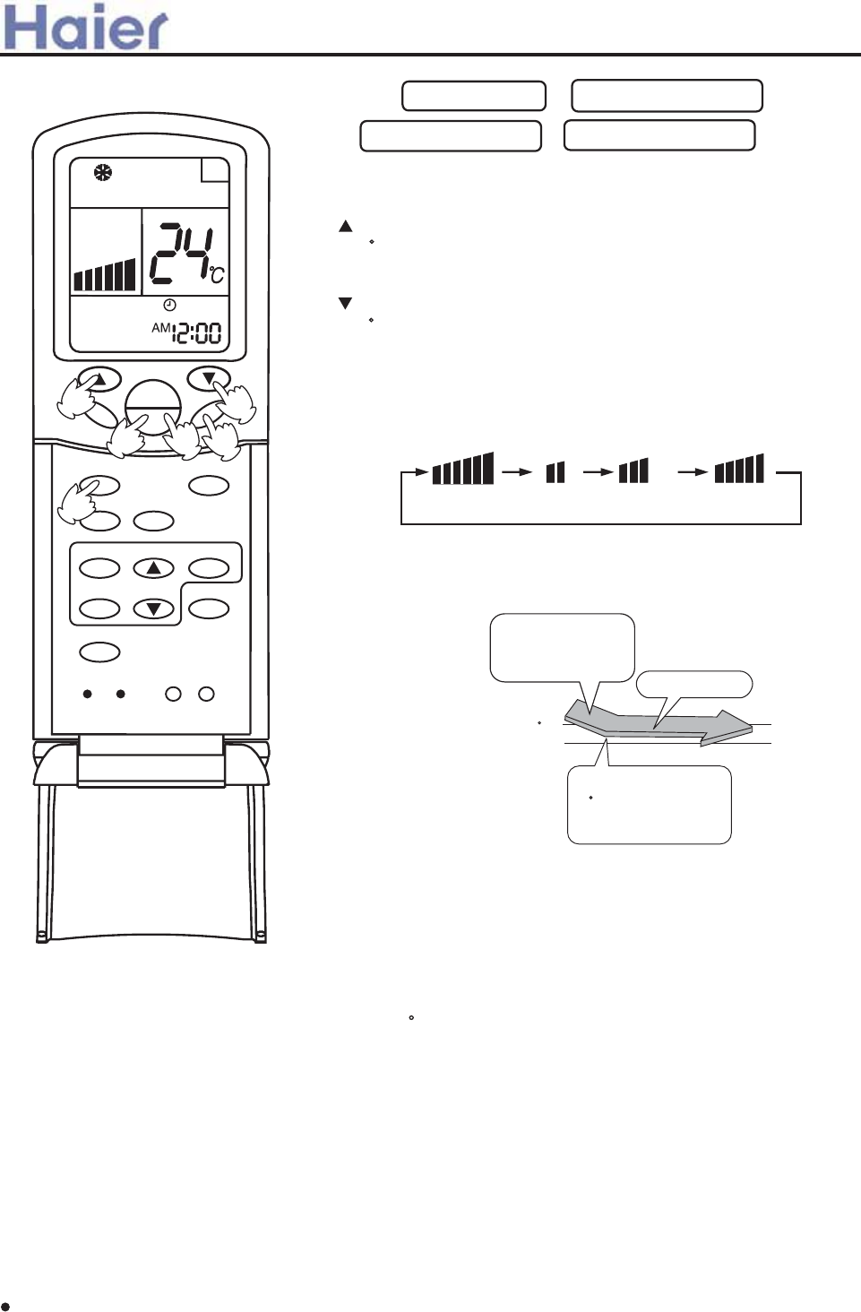
,|HU]`UbQdebU cUddY^W
HXU^ cU\USd 6IHD be^ _b cU\USd 8DDA _`UbQdY_^ _b
cU\USd 9FM _`UbQdY_^ _b cU\USd =:6H _`UbQdY_^
EbUcc H:BE Redd_^|
:fUbi dY]U dXU Redd_^ Yc `bUccUTzdU]`|cUddY^W Y^SbUQcUc
* 84 YV dXU Redd_^ Yc [U`d `bUccUTzdU]`|cUddY^W gY\\ Y^SbUQcU
aeYS[\i|
:fUbi dY]U dXU Redd_^ Yc `bUccUTzdU]`|cUddY^W TUSbUQcUc
*8zYV dXU Redd_^ Yc [U`d `bUccUTzdU]`|cUddY^W gY\\ TUSbUQcU
aeYS[\i|
GUd `b_`Ub dU]`UbQdebU
-|6TZecd ;6C Redd_^
EbUcc ;6C Redd_^|6d UQSX `bUcczVQ^ c`UUT SXQ^WUc Qc V_\\_gc3
6Yb S_^TYdY_^Ub gY\\ be^ Qd dXU cU\USdUT VQ^ c`UUT|
.|I^Yd cd_`
EbUcc DC}D;; Redd_^ze^Yd cd_`c|
>^ 6HID ]_TUzdXU dU]`UbQdebU cUddY^W Yc ^_d TYc`\QiUT _^ A89|>^ dXYc ]_TUzTebY^W be^^Y^W QYb S_^TYdY_^Ub
gY\\ cU\USd 8DDAz=:6H _b ;6C ]_TU Qed_]QdYSQ\\i QSS_bTY^W d_ dXU b__] dU]`UbQdebU|
>^ 9FM ]_TUzgXU^ b__] dU]`UbQdebU RUS_]Uc + 8 XYWXUb dXQ^ dU]`UbQdebU cUddY^Wze^Yd gY\\ be^ Y^dUb]YddU^d\i
Qd ADK c`UUT bUWQbT\Ucc _V ;6C cUddY^W|KXU^ b__] dU]`UbQdebU Yc \_gUb dXQ^ dU]`UbQdebU cUddY^Wze^Yd gY\\
_^\i be^ ;6C _`UbQdY_^|
>^ =:6H ]_TUzgQb] QYb gY\\ R\_g _ed QVdUb Q cX_bd `UbY_T _V dY]U TeU d_ S_\T{TbQVd `bUfU^dY_^ Ve^SdY_^|
6IHD ADK B>9 =><=
A
S
R
N
;F:G=
=><=}GD
H>B:F
G:H
;>AH:F
6
=:6AH=
F:G:H AD8@
GA::E
;6C
H:BE
DC
D;;
GK>C<
BD9:
8AD8@
8D9: A><=H
A
S
R
N
~
+|
~
*
}
HU]`|cUddY^W y+8
HU]`|cUddY^W
D^ bUQSXY^W dU]`|cUddY^W
y+8ze^Yd gY\\ be^ Y^ ]Y\T
9FM ]_TU|
I\dbQ{\_g QYb V\_g
8DDA _`UbQdY_^ cdQbdc
gXU^ b__] dU]`|Yc
XYWXUb dXQ^ dU]`|
cUddY^W|
EbUcc GK>C< Redd_^|I` Q^T T_g^ QYbV\_g fQbYUc e`gQbTc Q^T T_g^gQbTc|AUVd Q^T bYWXd QYbV\_g fQbYUc
\UVd Q^T bYWXd cYTUc|KXU^ dXU Qed_]QdYS cgY^W \_efUb ]_fUc d_ dXU `b_`Ub Q^W\Uz`bUcc GK>C< Redd_^
SQ^ VYh dXU QYbV\_g TYbUSdY_^|
6IHD GK>C<
A\bljkaf_ Yai ^dgn \ai][kagf
6\gQic ecU GK>C< Redd_^ _^ dXU bU]_dU S_^db_\\Ub d_ QTZecd V\Q`c|6TZecdY^W dXU] Ri XQ^T ]Qi bUce\d
Y^ QYb S_^TYdY_^Ubuc QR^_b]Q\\i be^^Y^W|
Cgee]i[aYd Aai Cgf\akagf]i
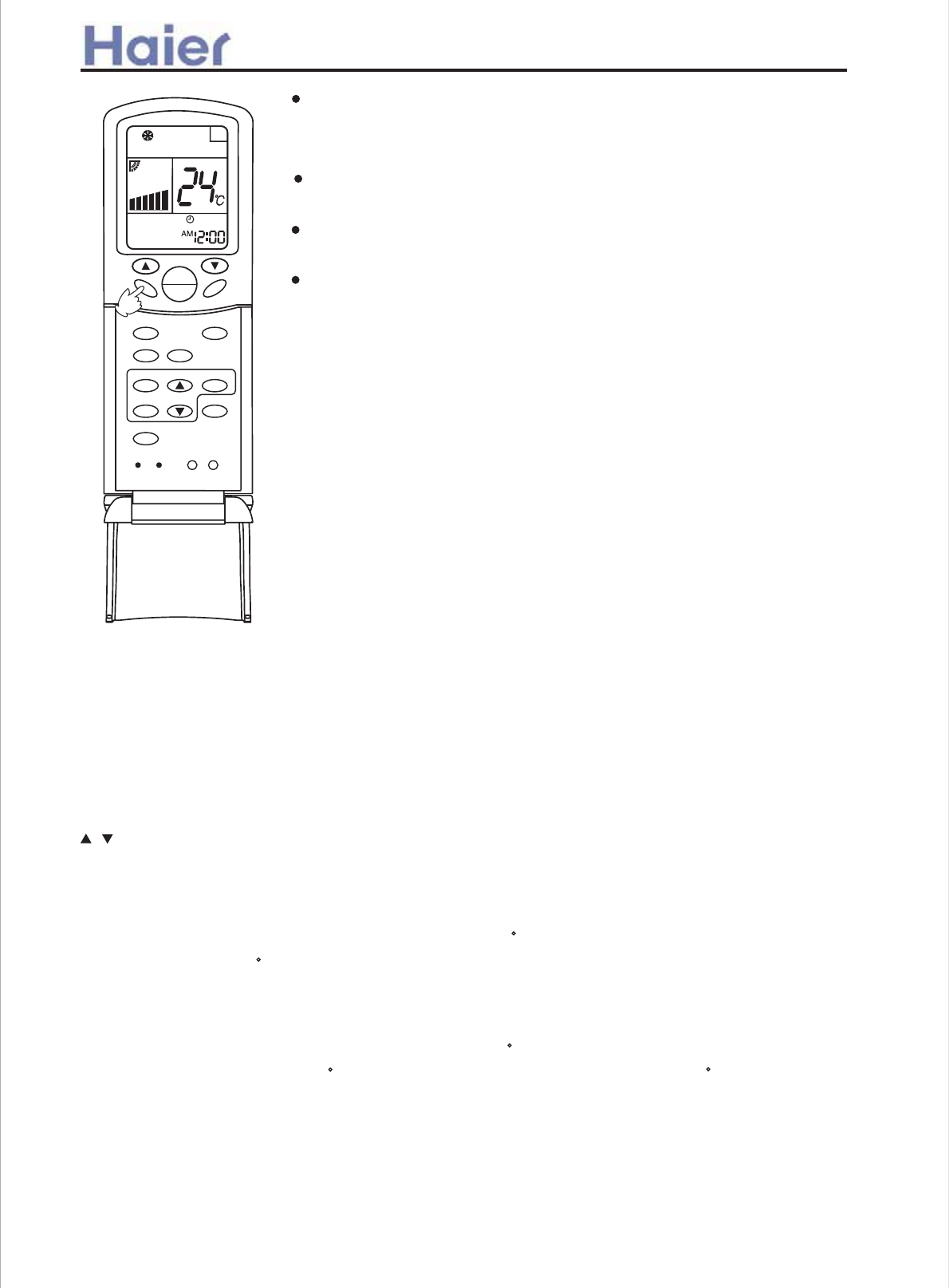
9Yc`\Qic _^ dXU A89 TYcQ``UQb|
6\\ Y^TYSQd_bc _^ dXU Y^T__b e^Yd W_ _ed|
GgY^W \_efUb Qed_]QdYSQ\\i S\_cU dXU QYb _ed\Ud|
A^k]i lfak jkghj?
E\UQcU SQbUVe\\i cUd dU]`UbQdebU gXU^ SXY\TbU^z_\T _b gUQ[ `U_`\U ecU
dXU QYb S_^TYdY_^Ub|
>^ SQcU _V WbUQd Xe]YTYdiz>V dXU fUbdYSQ\ V\Q`c QbU S_]`\UdU\i deb^UT
d_gQbTc \UVd _b bYWXdzdXU \_efUb gY\\ Tb_` gQdUb|
CUfUb QTZecd dXU \_efUb TYbUSd\i Ri XQ^TzQc dXYc S_e\T ]Q[U Yd g_b[
QR^_b]Q\\i|>V dXU \_efUb g_b[ QR^_b]Q\\izcd_` e^YdzbUcdQbd Q^T QTZecd dXU
\_efUb Ri bU]_dU S_^db_\\Ub|
Hafkj?
6c Y^ 8DDA ]_TU QYb V\_gc T_g^gQbTczQTZecdY^W QYbV\_g X_bYj_^dQ\\i gY\\
RU ]eSX ]_bU XU\`Ve\ V_b Q RUddUb QYb SYbSe\QdY_^ 6c Y^ =:6H ]_TU QYb V\_gc
e`gQbTczQTZecdY^W QYbV\_g T_g^gQbT gY\\ RU ]eSX ]_bU XU\`Ve\ V_b Q RUddUb
QYb SYbSe\QdY_^|7U SQbUVe\ ^_d d_ SQdSX Q S_\T gXU^ S_\T QYb R\_gc T_g^gQbT
TYbUSd\i|
>^ 8DDA _b 9FM ]_TUzT_ ^_d \UQfU dXU \_efUb Y^ T_g^gQbT `_cYdY_^ V_b
Q \_^W dY]UzQc dXU gQdUb fQ`_b S\_cU d_ dXU WbY\\U ]Qi S_^TU^cU Q^T gQdUb
]Qi Tb_` Vb_] dXU QYb S_^TYdY_^Ub|
;F:G=
=><=}GD
H>B:F
G:H
;>AH:F
6
=:6AH=
F:G:H AD8@
GA::E
;6C
H:BE
DC
D;;
GK>C<
BD9:
8AD8@
8D9: A><=H
A
S
R
N
Qd]]h Flf[kagf
7UV_bU W_Y^W d_ RUT i_e SQ^ `bUcc T_g^ dXU GA::E Redd_^ Q^T dXU QYb S_^TYdY_^Ub gY\\ be^ c_ Qc d_
]Q[U i_e c\UU` ]_bU S_]V_bdQR\i|7UV_bU ecY^W dXYc Ve^SdY_^zdXU S\_S[ ]ecd RU cUd|
Sj] g^ QKEEO ^lf[kagf
6VdUb dXU e^Yduc cdQbdzcUd be^^Y^W ]_TU Q^T dXU^ `bUcc GA::E Redd_^ _^SU d_ ]Q[U dXU QYb S_^TYdY_^Ub
XQfU dXU `bUfY_ec{cUd c\UU` dY]U vVYbcd `_gUb{_^ Yc t*Xtw| HXU c\UU` ci]R_\ gY\\ Q``UQb|
}3 EbUcc dY]U Redd_^zi_e SQ^ SX__cU dXU dY]U Y^ *k1 X_ebc|:QSX dY]U dXU Redd_^ Yc `bUccUTzdXU dY]U
Y^SbUQcUc}TUSbUQcUc * X_eb3 thXtQ^T tD;;tY^TYSQdY_^c Q``UQb _^ dXU TYc`\Qi|
D`UbQdY_^ B_TU
*|>^ 8DDAz9FM ]_TU
D^U X_eb QVdUb c\UU`Y^W _`UbQdY_^ cdQbdzdXU dU]`UbQdebU Yc * 8 XYWXUb dXQ^ dXU cUddY^W _^U|6VdUb Q^_dXUb
X_ebzdU]`UbQdebU bYcUc * 83 c\UU` be^ S_^dY^e_ec\i V_b Q^_dXUb / X_ebc Q^T dXU^ cd_`c|HXU QSdeQ\
dU]`UbQdebU Yc XYWXUb dXQ^ dXU cUddY^W _^U gXYSX Yc d_ `bUfU^d Vb_] RUY^W d__ S_\T d_ i_eb c\UU`|
+|>^ =:6H ]_TU
D^U X_eb QVdUb c\UU`Y^W _`UbQdY_^ cdQbdzdXU dU]`UbQdebU Yc + 8 \_gUb dXQ^ dXU cUddY^W _^U|6VdUb Q^_dXUb
X_ebzdU]`UbQdebU TUSbUQcUc Ri + 8 ]_bU|HU]`UbQdebU gY\\ Qed_]QdYSQ\\i bYcU Ri * 8 QVdUb Q^_dXUb
, X_ebcuS_^dY^e_ec _`UbQdY_^ HXU QSdeQ\ dU]`UbQdebU Yc \_gUb dXQ^
dXU cUddY^W _^U gXYSX Yc d_ `bUfU^d Vb_]|
,|>^ 6IHD ]_TU|
HXU QYb S_^TYdY_^Ub gY\\ be^ Y^ S_bbUc`_^TY^W c\UU` _`UbQdY_^ QSS_bTY^W d_ dXU Qed_]QdYSQ\\i cU\USdUT
_`UbQdY_^ ]_TU|
Cgee]i[aYd Aai Cgf\akagf]i
and keep running for another 3 hours.
RUY^W d__ X_d d_ i_eb c\UU`|
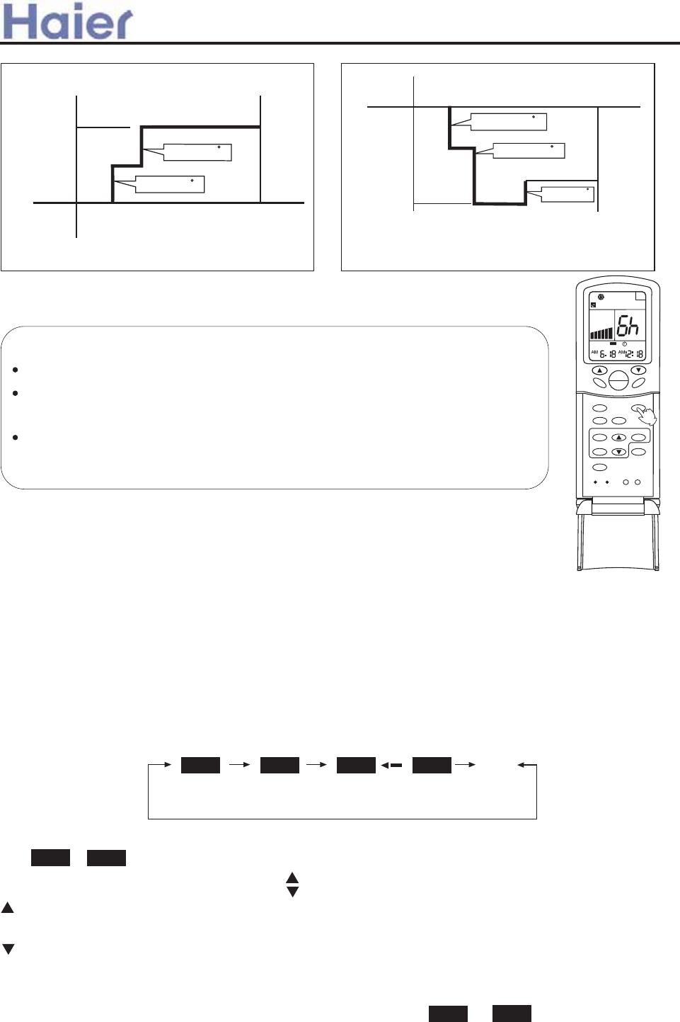
GA::E FIC 7:<>CG GA::E FIC GHDEG
G:HH>C< H:BE G=IH 9DKC
QR_ed / Xbc
* Xbc
>^ 8DDAz9FM ]_TU
Y^SbUQcU * 8
Y^SbUQcU * 8
GA::E FIC 7:<>CG GA::E FIC GHDEG
G:HH>C< H:BE G=IH 9DKC
* Xbc
* Xbc
, Xbc
Y^SbUQcU *8
TUSbUQcU + 8
TUSbUQcU + 8
>^ =:6H ]_TU
Mgk]j?
6VdUb cUddY^W GA::E Ve^SdY_^zYd Yc ^_d `_ccYR\U d_ cUd S\_S[|
>V cUd{c\UU` dY]U T_Uc ^_d bUQSX 1 X_ebcze^Yd gY\\ Qed_]QdYSQ\\i cd_` _`UbQdY_^
QVdUb cUd dY]U Yc bUQSXUT|
GUd tH>B:F DC t_b tH>B:F D;; t>^ 8DDAz9FM ]_TU Ve^SdY_^ VYbcdz
dXU^ cUd GA::E|6VdUb cUd GA::E Ve^SdY_^zdXU H>B:F Ve^SdY_^ SQ^^_d RU
cUd|
;F:G=
=><=}GD
H>B:F
G:H
;>AH:F
6
=:6AH=
F:G:H AD8@
GA::E
;6C
H:BE
DC
D;;
GK>C<
BD9:
8AD8@
8D9: A><=H
NFF
A
S
R
N
Rae]i NM4NFF Flf[kagf
GUd S\_S[ S_bbUSd\i RUV_bU cdQbdY^W H>B:F _`UbQdY_^
aeYS[\i|
*|I^Yd cdQbd
6VdUb e^Yd cdQbdzcU\USd i_eb TUcYbUT _`UbQdY_^ ]_TU v_`UbQdY_^ ]_TU gY\\ RU TYc`\QiUT _^ A89w
+|H>B:F ]_TU cU\USdY_^
EbUcc H>B:F Redd_^ _^ dXU bU]_dU S_^db_\\Ub d_ SXQ^WU H>B:F ]_TU|:fUbi dY]U dXU Redd_^ Yc `bUccUTz
TYc`\Qi _V H>B:F ]_TU SXQ^WUc Qc V_\\_gc3
HXU^ cU\USd H>B:F ]_TU Qc ^UUTUT vH>B:F DC _b H>B:F D;;w|
C_g _b gY\\ V\QcX|
,|H>B:F cUddY^W v`bUcc dY]U QTZecd Redd_^c w
:fUbi dY]U dXU Redd_^ Yc `bUccUTzdY]U TUSbUQcUc*~|>V dXU Redd_^ Yc [U`d `bUccUTzdY]U SXQ^WUc
aeYS[\i|>d SQ^ RU QTZecdUT gYdXY^ +- X_ebc Qd gY\\|
-|8_^VYb] cUddY^W
6VdUb cUddY^W S_bbUSd dY]Uz`bUcc G:H Redd_^ d_ S_^VYb] dY]U|C_g _b cd_` V\QcXY^W|
HY]U TYc`\QiUT3 e^Yd cdQbdc _b cd_`c Qd L X_eb L ]Y^ vH>B:F DC _b H>B:F D;;w
.|8Q^SU\ H>B:F ]_TU
?ecd `bUcc H>B:F Redd_^ cUfUbQ\ dY]Uc e^dY\ H>B:F ]_TU TYcQ``UQbc|
NM NFF
NM NFF
NM NFF NM NFF
6B*+3~~ EB*+3~~
H>B:F DC H>B:F D;; H>B:F DC{D;;
R\Q^[
6B*+3~~ EB*+3~~
Cgee]i[aYd Aai Cgf\akagf]i
QR_ed Xbc
,
:fUbi dY]U dXU Redd_^ Yc `bUccUTzdY]U Y^SbUQcUc *~|>V dXU Redd_^ Yc [U`d `bUccUTzdY]U SXQ^WUc
minutes
minutes
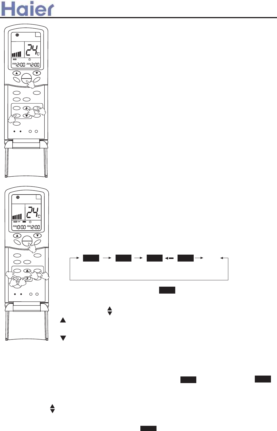
=Y^dc3
6VdUb bU`\QSY^W RQddUbYUc _b YV Q `_gUb VQY\ebU _SSebczH>B:F cUddY^W ]ecd RU bUcUd|
FU]_dU S_^db_\\Ub XQc ]U]_bi Ve^SdY_^|KXU^ i_e ecU H>B:F ]_TU ^Uhd dY]Uz
Zecd `bUcc G:H Redd_^ QVdUb ]_TU cU\USdY_^ YV dY]Ub cUddY^W Yc dXU cQ]U Qc dXU
`bUfY_ec _^U|
C_dU3
6VdUb cUddY^W H>B:F Ve^SdY_^zdXU bU]_dU S_^db_\\Ub TYc`\Qic H>B:F dY]U|>V i_e gQ^d
d_ cUU S\_S[ dY]UzZecd `bUcc 8AD8@ Redd_^ _^SU3 S\_S[ dY]U gY\\ RU TYc`\QiUT vYV i_e
`bUcc dXU Redd_^ QWQY^ S_^dY^e_ec\izi_e SQ^ QTZecd S\_S[w| . cUS_^Tc \QdUbzdXU
TYc`\Qi gY\\ cX_g H>B:F dY]U QWQY^|
Rae]i NM2NFF Flf[kagf
GUd S\_S[ S_bbUSd\i RUV_bU cdQbdY^W H>B:F _`UbQdY_^
*|I^Yd cdQbd
6VdUb e^Yd cdQbdzcU\USd i_eb TUcYbUT _`UbQdY_^ ]_TU v_`UbQdY_^ ]_TU gY\\ RU TYc`\QiUT
_^ A89w
+|H>B:F ]_TU cU\USdY_^
EbUcc H>B:F Redd_^ _^ dXU bU]_dU S_^db_\\Ub d_ SXQ^WU H>B:F ]_TU|:fUbi dY]U
dXU Redd_^ Yc `bUccUTzTYc`\Qi _V H>B:F ]_TU SXQ^WUc Qc V_\\_gc3
NFF
,|HY]U cUddY^W V_b H>B:F DC
-|HY]Ub S_^VYb]Y^W V_b H>B:F DC
6VdUb cUddY^W S_bbUSd dY]Uz`bUcc H>B:F Redd_^ d_ S_^VYb] dY]U|C_g
.|HY]Ub cUddY^W V_b H>B:F D;;
EbUcc dY]U Redd_^c Q^T V_\\_g dXU cQ]U `b_SUTebUc Y^ tHY]U cUddY^W V_b H>B:F DCt
EbUcc dY]U Redd_^
NM
cd_`c d_ V\QcXzgXY\U
cdQbdc V\QcXY^W|
/|HY]U S_^VYb]Y^W V_b H>B:F D;;
6VdUb dY]U cUddY^Wz`bUcc G:H Redd_^ d_ S_^VYb] dY]U|cd_`c d_ V\QcX|
HY]U TYc`\QiUT3 |
NM
HXU^ cU\USd H>B:F DC{D;; ]_TU|gY\\ V\QcX|
:fUbi dY]U dXU Redd_^ Yc `bUccUTzdY]U Y^SbUQcUc *~|
>V dXU Redd_^ Yc [U`d `bUccUTzdY]U gY\\ SXQ^WUc aeYS[\i|
:fUbi dY]U dXU Redd_^ Yc `bUccUTzdY]U TUSbUQcUc *~|
>V dXU Redd_^ Yc [U`d `bUccUT zdY]U gY\\ SXQ^WUc aeYS[\i|
>d SQ^ RU QTZecdUT gYdXY^ +- X_ebc Qd gY\\|
6B bUVUbc d_ ]_b^Y^W Q^T EB bUVUbc d_ QVdUb^__^|
NFF
NM NFF NM NFF
H>B:F DC H>B:F D;; H>B:F DC{D;;
R\Q^[
;F:G=
=><=}GD
H>B:F
G:H
;>AH:F
6
=:6AH=
F:G:H AD8@
GA::E
;6C
H:BE
DC
D;;
GK>C<
BD9:
8AD8@
8D9: A><=H
|
}
~*
;F:G=
=><=}GD
H>B:F
G:H
;>AH:F
6
=:6AH=
F:G:H AD8@
GA::E
;6C
H:BE
DC
D;;
GK>C<
BD9:
8AD8@
8D9: A><=H
NFF
|
~,
+
*
}
EB*+3~~
6B*+3~~ 6B*+3~~ EB*+3~~
Cgee]i[aYd Aai Cgf\akagf]i
minutes
minutes
e^Yd cdQbdc _b cd_`c Qd L X_eb L ]Y^
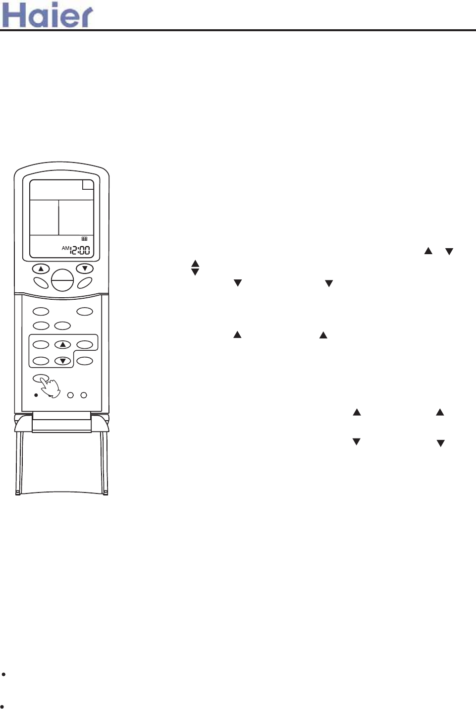
0|8Q^U\ H>B:F ]_TU
?ecd `bUcc H>B:F Redd_^ cUfUbQ\ dY]Uc e^dY\ H>B:F ]_TU TYcQ``UQbc|6SS_bTY^W d_ dXU dY]U cUddY^W
cUaeU^SU _V H>B:F DC Q^T H>B:F D;;zUYdXUb cdQbd{cd_`c _b cd_`c{cdQbd SQ^ RU bUQ\YjUT|
>V dXU dY]U cUddY^W _V H>B:F DC Yc dXU cQ]U Qc H>B:F D;;zH>B:F DC{D;; Ve^SdY_^ SQ^^_d RU cUd|
6VdUb dXU QYb S_^TYdY_^Ub XQc _`UbQdUT V_b Q SUbdQY^ `UbY_TzTecd XQc
QSSe]e\QdUT _^ dXU VY\dUbzQ^T dXU VY\dUb e`}T_g^ Ve^SdY_^ SQ^ RU ecUT d_
S\UQ^ Yd|
*|KXUdXUb e^Yd cdQbdc _b cd_`czS_^dY^e_ec\i `bUcc ;>AH:F Redd_^ V_b , cUS_^Tc z
Q^T U^dUb dXU VY\dUb e`}T_g^ gQYdY^W cdQdec vgXU^ e^Yd cd_`czdXU iU\\_g H>B:F
Y^TYSQd_b V\QcXUczQ^T VY\dUb Q^T S\_S[ Y^TYSQdY_^ QbU TYc`\QiUT _^ dXU bU]_dU
S_^db_\\Ub|D^\i dXU ;>AH:F Redd_^zdXU dU]`UbQdebU Redd_^c ttttQ^T
dY]U Redd_^c QbU QSdYfUw|
+|EbUcc dU]`UbQdebU ttRedd_^ _b dY]U ttRedd_^ Y^ VY\dUb e`}T_g^
gQYdY^W cdQdec3 dXU e`}T_g^ ]USXQ^Yc] ]Q[Uc dXU VY\dUb ]_fY^W T_g^gQbT
Q^T T_Uc ^_d cd_` e^dY\ Yd XQc bUQSXUT dXU ]QhY]e] \Y]Yd|
,|EbUcc dU]`UbQdebU ttRedd_^ _b dY]UttRedd_^ Y^ VY\dUb e`}T_g^ gQYdY^W
cdQdec3 dXU e`}T_g^ ]USXQ^Yc] ]Q[Uc dXU VY\dUb d_ ]_fY^W e`gQbT dY\\ ^UQb
dXU cebVQSU R_QbT Q^T dXU^ Qed_]QdYSQ\\i QTZecdc Yd d_ bUcUd vgXU^ QTZecdY^W
d_ bUcUdzYd gY\\ ^_d RU S_^db_\\UT Ri dXU bU]_dU S_^db_\\Ub dY\\ dXU QTZecd]U^d Yc
VY^YcXUTw|
-|9ebY^W ]_fY^W T_g^gQbTz`bUcc dU]`UbQdebUttRedd_^ _b dY]U ttRedd_^3
]_fY^W cd_`c|
/|8_^dY^e_ec\i `bUcc ;>AH:F Redd_^ , cUS_^Tc QWQY^ d_ SQ^SU\ dXU VY\dUb
e`}T_g^ gQYdY^W ]_TU ve^Yd cd_`czdXU iU\\_g dY]Ub Y^TYSQd_b cd_`c V\QcXY^W z
dXU VY\dUb W_Uc RQS[ d_ dXU _bYWY^Q\ `_cYdY_^zdXU bU]_dU S_^db_\\Ub W_Uc RQS[
d_ _VV cdQdec Q^T _^\i S\_S[ Yc TYc`\QiUTw|
C_dU3
>V dXU VY\dUb T_Uc ^_d dX_b_eWX\i W_ RQS[ d_ dXU _bYWY^Q\ `_cYdY_^z_^\i ^UUTc d_ _`UbQdU cUfUbQ\ dY]Uc
bU`UQdUT\i|
Fadk]i Sh4Dgnf
vD^\i V_b /~~x/~~ `Q^U\ _V cY^W\U e^Yd.
;F:G=
=><=}GD
H>B:F
G:H
;>AH:F
6
=:6AH=
F:G:H AD8@
GA::E
;6C
H:BE
DC
D;;
GK>C<
BD9:
8AD8@
8D9: A><=H
|
.|9ebY^W ]_fY^W T_g^gQbTz`bUcc dU]`UbQdebUttRedd_^ _b dY]U ttRedd_^3
]_fY^W cd_`c|
+ Ha_` eg\] + Nh]iYkagf
Nlkdaf] g^ gh]iYkagf af +Ha_` Lg\]+
HXYc Ve^SdY_^ Yc ceYdQR\U gXU^ dXU cUd dU]`UbQdebU ]ecd RU bUQSXUT Y^ dXU cX_bdUcd TU\Qi|HXU Redd_^
t=><=}GDtz bUVUbbUT d_ dXYc Ve^SdY_^zYc UVVUSdYfU Y^ 8__\Y^W}=UQdY^W ]_TU v^_d Y^ 6ed_}9bi};Q^ ]_TUc w|
CDH>8:3
KXU^ dXU QYb S_^TYdY_^Ub Yc _`UbQdY^W Y^ t=YWX B_TU tze^UfU^^Ucc _V b__] QYb dU]`UbQdebU ]Qi _SSeb TeU
d_ dXU Y^dU^cYfU _`UbQdY_^ Y^ Q cX_bd dY]U|
6^igQiz_`UbQdY_^ Y^ t=YWX B_TUtz T_Uc ^_d \Qcd V_b ]_bU dXQ^ *. ]Y^edUczdXU^ bUWe\Qb _`UbQdY_^ Yc
Qed_]QdYSQ\\i bUcd_bUT|
Cgee]i[aYd Aai Cgf\akagf]i
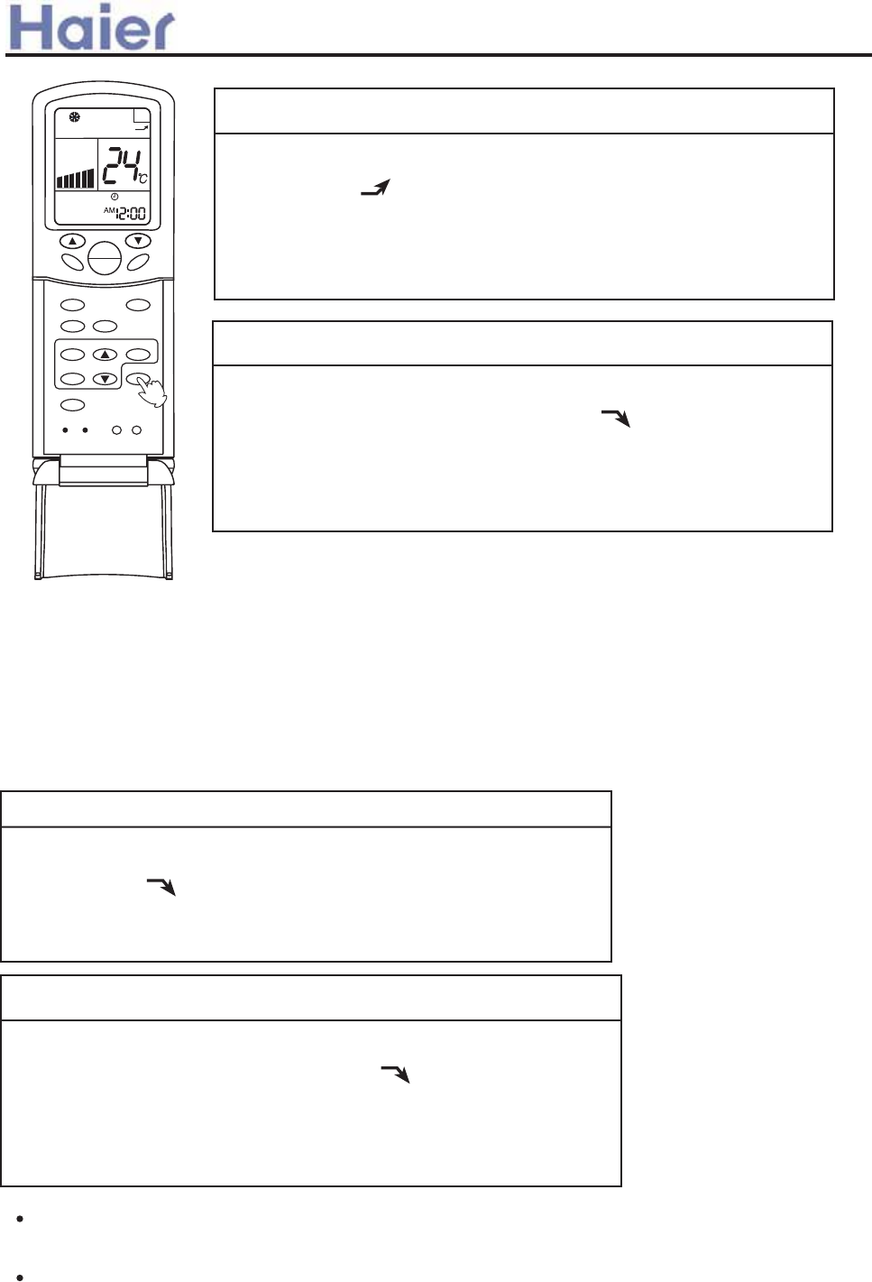
Oi]jj k`] HIGH4QN Zlkkgf kna[]
>V dXU Redd_^ Yc `bUccUT _^SUzdXU Y^TYSQdY_^ Yc TYc`\QiUT _^ dXU
bU]_dU S_^db_\\Ub|>V i_e `bUcc dXU Redd_^ _^SU QWQY^zdXU Y^TYSQdY_^
TYcQ``UQbczbUWe\Qb _`UbQdY_^ Yc bUcd_bUT Q^T VQ^ c`UUT W_Uc RQS[ d_ dXU
]_TU cUd RUV_bU t=YWX B_TUt_`UbQdY_^|
Oi]jj k`] HIGH4QN Zlkkgf fg[]
HXU Y^TYSQdY_^ Q``UQbc _^ dXU TYc`\Qi _V dXU bU]_dU S_^db_\\Ub
Q^T _`UbQdY_^ Y^ t=YWX B_TUtcdQbdc|
HXU 6IHD VQ^ c`UUT Yc Qed_]QdYSQ\\i cUd Q^T dXU S_bbUc`_^TY^W Y^TYSQdY_^
Yc Q\c_ TYc`\QiUT|
NM
NFF
Oi]jj k`] HIGH4QN Zlkkgf kna[]
MNRICE?
KXU^ dXU QYb S_^TYdY_^Ub Yc _`UbQdY^W Y^ t=YWX B_TU tze^UfU^^Ucc _V b__] QYb dU]`UbQdebU ]Qi _SSeb
TeU d_ dXU Y^dU^cYfU _`UbQdY_^ Y^ Q cX_bd dY]U|
6^igQiz_`UbQdY_^ Y^ t=YWX B_TUtz T_Uc ^_d \Qcd V_b ]_bU dXQ^ *. ]Y^edUczdXU^ bUWe\Qb _`UbQdY_^ Yc
Qed_]QdYSQ\\i bUcd_bUT|
+ Qg^k eg\] + Nh]iYkagf
>V dXU Redd_^ Yc `bUccUT _^SUzdXU Y^TYSQdY_^ Yc TYcQ``UQbc Vb_] dXU
bU]_dU S_^db_\\Ubuc TYc`\Qi|>V i_e `bUcc dXU Redd_^ _^SU QWQY^zbUWe\Qb
_`UbQdY_^ Yc bUcd_bUT Q^T VQ^ c`UUT W_Uc RQS[ d_ dXU ]_TU cUd RUV_bU
tG_Vd B_TUt_`UbQdY_^|
Oi]jj k`] HIGH4QN Zlkkgf kna[]
HXU Y^TYSQdY_^ Q``UQbc _^ dXU TYc`\Qi _V dXU bU]_dU S_^db_\\Ub
Q^T _`UbQdY_^ Y^ tG_Vd B_TUtcdQbdc|HXU 6IHD VQ^ c`UUT Yc
Qed_]QdYSQ\\i cUd Q^T dXU S_bbUc`_^TY^W Y^TYSQdY_^ Yc Q\c_ TYc`\QiUT|
Nlkdaf] g^ gh]iYkagf af +Qg^k Lg\]+
D`UbQdY_^ Y^ tG_Vd B_TUtz ]_bU cY\U^dzYc ceYdQR\U gXU^ ^_YcUc cX_e\T RU bUTeSUTzU|W|| V_b bUQTY^W _b
c\UU`Y^W|HXU Redd_^ t=><=}GDtz bUVUbbUT d_ dXYc _`UbQdY_^zYc UVVUSdYfU Y^ 8__\Y^W}=UQdY^W ]_TU v^_d Y^
6ed_}9bi};Q^ ]_TUcw|
NM
NFF
;F:G=
=><=}GD
H>B:F
G:H
;>AH:F
6
=:6AH=
F:G:H AD8@
GA::E
;6C
H:BE
DC
D;;
GK>C<
BD9:
8AD8@
8D9: A><=H
A
S
R
N
|
Cgee]i[aYd Aai Cgf\akagf]i
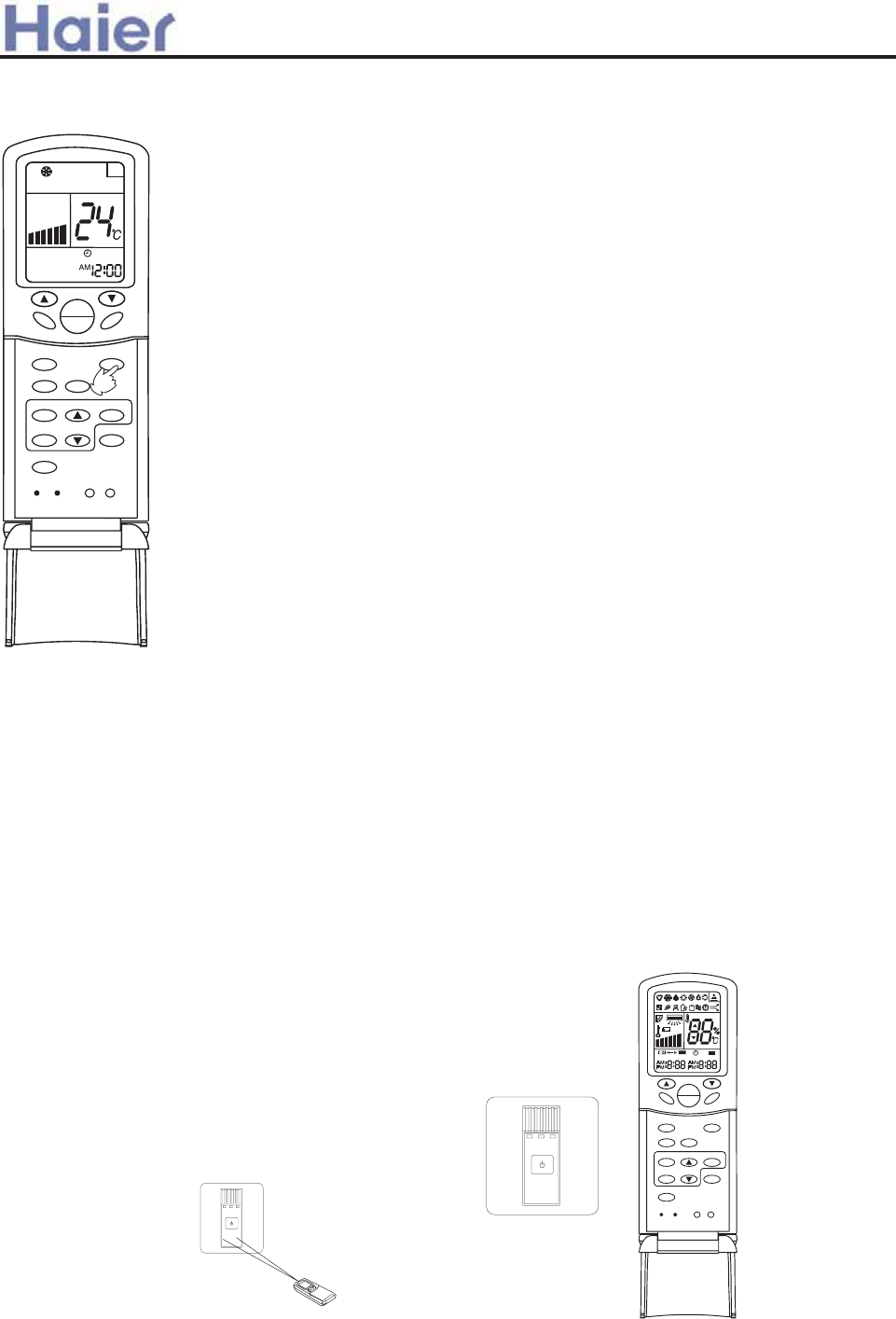
Alkg i]jkYik ^lf[kagf j]kkaf_
Q]kkaf_ L]k`g\? KXU^ dXU bU]_dU S_^db_\\Ub Yc _^ vUhS\eTY^W dY]Ub ]_TU
Q^T VQ^ ]_TUwz`bUcc dXU tG\UU`tRedd_^ _^ dXU bU]_dU S_^db_\\Ub *~dY]Uc
gYdXY^ .cUS_^TczQ^T QVdUb dXU RejjUb bY^Wc - dY]UczdXU QYb S_^TYdY_^Ub gY\\
U^dUb dXU cdQdU _V Qed_ bUcdQbd|
CYf[]d L]k`g\? EbUcc dXU tG\UU`Y^WtRedd_^ _^ dXU bU]_dU S_^db_\\Ub *~
dY]Uc gYdXY^ .cUS_^TczQ^T QVdUb dXU RejjUb bY^Wc + dY]UbzdXU Qed_ bUcdQbd
]_TU gY\\ RU SQ^SU\\UT|
Mgk]j? KXU^ Q `_gUb VQY\ebU ceTTU^\i _SSebc TebY^W dXU QYb S_^TYdY_^Ub Yc g_b[
Y^W QVdUb dXU `_gUb VQY\ebU S_]`U^cQdY_^ Yc cUdzYV dXU QYb S_^TYdY_^Ub gY\\ ^_d RU
ecUT V_b Q \_^W dY]Uz`\UQcU Sed _VV dXU `_gUb ce``\i d_ `bUfU^d Ydc _`UbQdY_^ Vb_]
RUY^W bUce]UT QVdUb dXU `_gUb Yc ce``\YUT QWQY^z_b `bUcc dXU tGgYdSX D^}DVVt
Redd_^ QVdUb dXU `_gUb S_]Uc QWQY^|
6VdUb dXU `_gUb VQY\ebU S_]`U^cQdY_^ Yc cUdzYV `_gUb VQY\ebU ceTTU^\i _SSebc gXY\U dXU
QYb S_^TYdY_^Ub Yc g_b[Y^WzYd gY\\ bUce]U dXU `bUfY_ec g_b[Y^W cdQdU gXU^ dXU `_gUb
Yc ce``\YUT QWQY^|
I^ k`] lfak `Yj fgk k`] +jd]]h+ Zlkkgf gi ^lf[kagf1 hd]Yj] i]Ydaq] k`] ^lf[kagf
Zp hi]jjaf_ +jnaf_+ nak` k`] jYe] e]k`g\3
;F:G=
=><=}GD
H>B:F
G:H
;>AH:F
6
=:6AH=
F:G:H AD8@
GA::E
;6C
H:BE
DC
D;;
GK>C<
BD9:
8AD8@
8D9: A><=H
A
S
R
N
Mgk]?
Cgee]i[aYd Aai Cgf\akagf]i
HXU bYWXd VYWebU Yc Q bU]_dU S_^db_\\UbzgXYSX SQ^ RU ecUT _^
cUbYUc
bU]_dU S_^db_\ e^Ydc Q^T dXU
]QdSXY^W bU]_dU S_^db_\ bUSUYfUb
*|FU]_dU S_^db_\ bUSUYfUb ecY^W ]UdX_T 3
IcU bU]_dU S_^db_\\Ub S_^db_\ dXU
bU]_dU S_^db_\ gY^T_g _V dXU bU]_dU
S_^db_\ bUSUYfUb|
Lldka lfakj1 k`] [gfkigdd]i CNDE hd]Yj]
j]d][k [g\] +A+@ ^gi H2LPT Yf\ AQ//V
ABAA lfak1 hd]Yj] j]d][k [g\] +B+3
Q^T dXU bU]_dU S_^db_\\Ub MF{=0* d_ bUQ\YjU dXU bU]_dU Ve^SdY_^|HXU Y^cdQ\\QdY_^ _V bU]_dU bUSUYfUb
Q^T ecQWU Ve^SdY_^ QbU Qc V_\\_gc3
If^iYi]\ [gfkigdd]i WP2H<6 Yf\ i]egk] i][]am]i PE256?
;F:G=
=><=}GD
H>B:F
G:H
;>AH:F
76
B9
=:6AH=
F:G:H AD8@
GA::E
;6C
H:BE
DC
D;;
GK>C<
BD9:
8AD8@
8D9: A><=H
NFF
A
S
R
N
FU]_dU S_^db_\\\Ub
FU]_dU bUSUYfUb
73Fgi SfakYip Fi]]1 SfakYip QeYik Yf\
HXYc [Y^T _V bU]_dU S_^db_\\Ub SQ^ RU ecUT V_b Q\\ IC>H6FM Y^T__b e^Ydc UhSU`d V_b 6E*1+687:6|
>V dXU e^Yd Yc gYbUT di`U Q^T Yd Yc gYdX_ed dXU bU]_dU bUSUYfUbzi_e SQ^ ecU dXU bU]_dU bUSUYfUb F:{~*
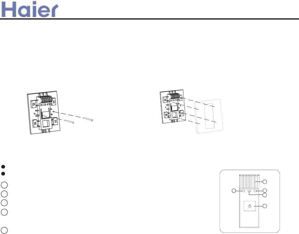
Cgee]i[aYd Aai Cgf\akagf]i
8_^^USdY^W gYbY^W ]UdX_T _V bUSUYfUb 3
FUVUb dXU Y^T__b e^Yd gYbY^W TYQWbQ] |
GQVUdi SQedY_^c cUU dXU U\USdbYSQ\ gYbY^W `Qbd |
*|:]UbWU^Si cgYdSX
+|Fe^^Y^W \Q]`3 KXU^ dXU S_]`bUcc_b g_b[Y^WzdXYc \Q]` RbYWXd|
,|HY]Y^W \Q]`3 KXU^ dXU e^Yd RUU^ cUddY^W HY]Y^W be^^Y^WzdXYc \Q]` RbYWXd|
-|E_gUb \Q]`3 6VdUb _`U^ dXU e^YdzdXYc \Q]` RbYWXd gXU^ dXU e^YdU U^dUb
XUQ\dX be^^Y^WzdXU \Q]` SXQ^WU Vb_] _bQ^WU d_ R\eU \Q]`|
.|>^T__b dU]`|cU^c_b3 HUcd dXU b__] dU]`UbQdebU|
|
~
*
+
}
>^cdQ\\QdY_^ _V bUSUYfU TYc`\Qi
7USQecU _V dXU dU]`UbQdebU cU^cYdYfU TUfYSUzT_ ^_d Y^cdQ\\ dXU bUSUYfU TYc`\Qi Qd cdbQYWXd ce^\YWXd `\QSUz
UYdXUb Y^ Vb_^d _V QYb _ed\Ud WbY\\zV_b Yd Yc UVVUSdUT WbUQd\i Vb_] S__\ QYb Q^T XUQd QYbzdXU bUSUYfU TYc`\Qi Yc
Qd \UQcd +~]] TYcdQ^SU d_ dXU QYb _ed\Ud WbY\\|
GY^SU dXUbU Yc \YWXd cU^cYdYfU TUfYSU gXYSX bUSUYfUc gYbU\Ucc bU]_dU cYW^Q\zc_ T_ ^_d Y^cdQ\\UT RUXY^T dXU
gY^T_g SebdQY^ _b _dXUb _RcdQS\UczY^ _bTUb ^_d d_ _RcdbeSd dXU cYW^Q\|
Becd VYh dXU bU]_dU S_^db_\ gYbU VQb Vb_] cdb_^W U\USdbYSYdi vceSX Qc dXU gYbY^W _V U\USdbYS \YWXdzQYb S_^T{
YdY_^UbzUdS|w Q^T gUQ[ U\USdbYSYdi vceSX Qc dXU gYbY^W _V dU\U`X_^UzY^dUb`X_^UzUdS|w|
+|E\QSU dXU `Q^U\ _^d_ dXU VYhUT VbQ]Uz`Qi QddU^dY_^
dXQd dXU V_eb S\Qgc ]ecd RU `\QSUT Y^d_ dXU
S_bbUc`_^TY^W V_eb `_\Uc _^ dXU VbQ]U
*|;Yh dXU bUSUYfU TYc`\Qi gYdX cSbUgc
_^ dXU cU\USdUT `\QSU
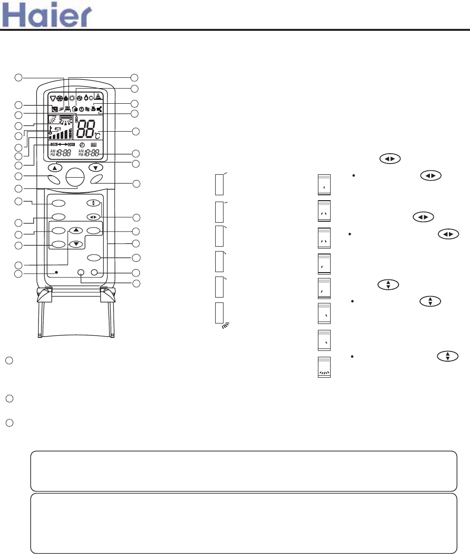
Cgee]i[aYd Aai Cgf\akagf]i
EDK:F}GD;H
~{
:hSU`d OGK>C<POEDK:F}GD;HPO=:6HP Ve^SdY_^zdXU _dXUb RQcYS
Ve^SdY_^c QbU cQ]U gYdX MF{=0*z`\UQcU bUVUbU^SU MF{=0* ]Q^eQ\|
OGgY^WP Ve^SdY_^ TUcSbY`dY_^3
Aai ^dgn Y\bljke]fk
GgY^W \_efUbc
vJUbdYSQ\ \_efUbcw
I` Q^T T_g^ AUVd Q^T bYWXd
v=_bYj_^dQ\ \_efUbcw
;YhUT `_cYdY_^
EbUcc dXU GK>C<
QWQY^ d_ VYh dXU X_bYj_^dQ\
\_efUbc Qd i_eb TUcYbUT
`_cYdY_^|
GgY^W
EbUcc GK>C< dXU
X_bYj_^dQ\ \_efUbc ]_fU
Vb_] e` d_ T_g^|
;YhUT `_cYdY_^
EbUcc dXU GK>C<
QWQY^ d_ VYh dXU fUbdYSQ\
\_efUbc Qd i_eb TUcYbUT
`_cYdY_^|
GgY^W
EbUcc GK>C< dXU
fUbdYSQ\ _efUbc ]_fU Vb_]
\UVd Q^T bYWXd|
=:6H
GU\USd 6ehY\YQbi U\USdbYS XUQdUb
EDK:F}GD;H
GU\USd `_gUb}c_Vd
}/
~{
IcUT d_ cUd IE}9DKC QYb cU^TY^W Q^T F><=H
}A:;H QYb cU^TY^W TYbUSdY_^|
GK>C<
Eed \_efUbc Qd e` `_cYdY_^ Y^ S__\Y^W Q^T T_g^ `_cYdY_^ Y^ XUQdY^W ]_TU|
HXYc gY\\ RU XU\`Ve\ d_ [UU` Q^ UfU^ b__] dU]`|
C_dU3
>^ S__\Y^W _b Tbi _`UbQdY_^zT_^ud `ed X_bYj_^dQ\ \_efUbc Qd T_g^gQbT `_cYdY_^ V_b
Q \_^W dY]Uz_b _ed\Ud WbY\\ ]YWXd WUd Vb_cdUT|9_^ud Uh`_cU i_eb c[Y^ d_ S__\ _b gQb]
QYb V_b Q \_^W dY]U|
C_dU3
DC
D;;
H:BE
=:6AH= ;6C
BD9:
GA::E GK>C<
8AD8@
H>B:F
G:H
AD8@A><=H
F:G:H
}
=:6H
}/
|
~
*
+
,
-
.
/
|{
||
|}
|~
|*
|+
|,
|-
|.
|/
}|
}~
}*}+
},
}.
}{
76
}-
}}
|~
E_cYdY_^ *
E_cYdY_^ +
E_cYdY_^ ,
E_cYdY_^ -
E_cYdY_^ .
E_cYdY_^ /
E_cYdY_^ 0
E_cYdY_^ 1
O8DDA}9FM};6
C}6IHDv8DDAw
=6J: CDHP
v6IHD GK>C<w
E_cYdY_^ *
E_cYdY_^ +
E_cYdY_^ ,
E_cYdY_^ -
E_cYdY_^ .
E_cYdY_^ /
637 If^iYi]\ [gfkigdd]i WP2H:5
Note: For new apperance convertible unit, the position 3 and position 4 are "Auto Swing".
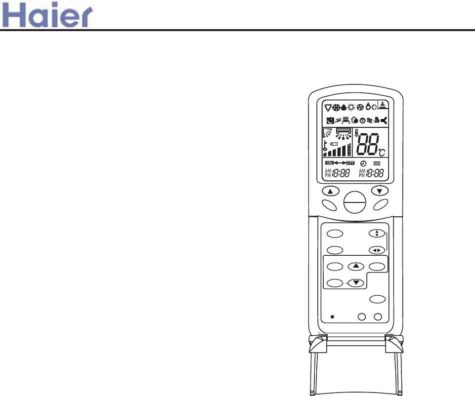
Cgee]i[aYd Aai Cgf\akagf]i
638 If^iYi]\ [gfkigdd]i
WP2H9>
HXU ]QY^ Ve^SdY_^c _V MF{=-2 QbU cQ]U gYdX MF{=.~z `\UQcU
bUVUbU^SU MF{=0* Q^T MF{=.~]Q^eQ\c|
DC
D;;
H:BE
=:6AH= ;6C
BD9:
GA::E GK>C<
8AD8@
H>B:F
G:H
AD8@A><=H
F:G:H
=:6H
76
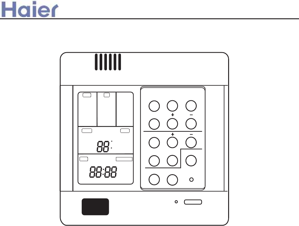
Buttons function˖
MODE˖used for select indoor operation mode.
FAN˖used for select indoor air flow.
SWING˖used for setting indoor swing mode.
HEALTH˖used for setting indoor health function.
TEMP + -˖used for changing set temperature.
CLOCK˖used to adjust time.
+ǃ-˖stands for time plus/minus, used to adjust time.
TIMER˖used to set timer mode.
RECOVERY˖used to switch over air-exchanging mode.
CHECK˖auto-diagnostic button.
FILTER˖filter-cleaned button.
RESET˖reset correct mode button.
Display description˖
[MODE] [AUTO]˖auto operation mode
[MODE] [FAN ONLY]˖air-throwing mode
[MODE] [COOL]˖Cooling operation mode
[MODE] [DRY]˖Dehumidification mode
[MODE] [HEAT]˖Heating operation mode
[MODE] [HEAT] [TES]˖In heating mode, auxiliary electric heater is running. Only when the
unit with auxiliary electric heater is in auxiliary electric heating mode, it will display.
[FAN] [AUTO]˖auto fan running
*
740:A7
+
;=34 50< @D8<6
A4;>
2:=29
A8;4? @4A ?42=C4?F
27429 58:A4? ?4@4A
;=34 50<
0BA= 0BA=
50< =<:F
2==:
3?F
740A
A4@
7867
;43
:=D
58E
24<A?0:
=>4?0A8=<
@A0<31F
>?4-740A
345?=@A
58:A4?
740:A7 27429 @D8<6
B<8A <=. 34;0<3 ;0<B0:
24<.033.
@F@.033.
?==; A4;>.
@4A A4;>.
A8;4? 2:=29 B> 3=D< C4<A8:0A8=<
=<
=55
308:F
0BA=
?42=C4?F
<=?;0:
=</=55
>a__WcU[S^ <[c>a`V[e[a`Wc
2. Wired controller

[FAN] [HIGH]˖high fan speed
[FAN] [MED]˖ medium fan speed
[FAN] [LOW]˖ low fan speed
[FAN] [FIX]˖ fixed fan speed, it will display only when fixed fan speed is requested to main
indoor unit.
[CENTRAL]˖ central control mode
[OPERATION] ˖running mode
[STAND BY] ˖ waiting mode
[PRE-HEAT] ˖ pre-heating mode
[DEFROST]˖ defrosting mode
[FILTER] ˖ request of filter to be cleaned
[HEALTH]˖health function
[UNIT NO.]
[CEN.ADD]˖central control address, the address number will display on “88ā
[SYS.ADD.]˖system address, the address number will display on “88ā
[SWING]˖swing mode
[ROOM TEMP.]˖indoor ambient temperature
[TIMER][OFF] ˖timer function is off
[TIMER][ON][OFF] ˖timer function ON-OFF
[TIMER][ON][OFF][DAILY]˖timer ON-OFF will switch over in turn daily
[CLOCK]˖clock display, the displaying time is the current time of the clock.
[UP]ǃ[DOWN]˖indicator of filter elevating
[VENTILATION][AUTO]˖auto ventilation mode
[VENTILATION][RECOVERY]˖fully heat exchanging ventilation mode
[VENTILATION][NORMAL]˖normal ventilation mode
FAN ONLY OPERATION
˖
1˅Start up operation: press the button of ON/OFF, the system will start up, and will display
[MODE][AUTO]˗[FAN][AUTO]˗[ROOM TEMP.]+Ā24ćā˗[CLOCK]+”12˖00”.
2˅ Select MODE: press the MODE button, then you will see in the display section [MODE]
switch over in below sequence:[FAN ONLY]ė[COOL]ė[DRY]ė[HEAT]ė[AUTO]ė
[FAN ONLY]. Select [FAN ONLY].
3˅Select fan speed: press FAN button, then you see in the display section [FAN] switch over
in below sequence: [HIGH]ė[MED]ė[LOW]ė[HIGH]. Select proper fan speed.
4˅Power off: press ON/OFF button, indoor unit will be powered off, there are only time and
the ambient temperature in the screen.
>a__WcU[S^ <[c>a`V[e[a`Wc
[TIMER][ON] ˖timer function is on.
[CHECK]˖auto-diagnostic, trouble shooting
[DEMAND]˖compulsory operation function, when it works, [CENTRAL] will flash
[SET TEMP.]˖set admired temperature.

AUTO operation, COOLING, HEATING and DEHUMIDIFICATION operation
1) Start up operation: press the button of ON/OFF, the system will start up, and will display
[MODE][AUTO]˗[FAN][AUTO]˗[ROOM TEMP.]+Ā24ćā˗[CLOCK]+”12˖00”.
2) Select MODE: press the MODE button, then you will see in the display section [MODE]
switch over in below sequence:[FAN ONLY]ė[COOL]ė[DRY]ė[HEAT]ė[AUTO]ė[FAN
temperature will increase/reduce 1ć˄F˅.
4) Select fan speed: press FAN button, then you see in the display section [FAN] switch over
in below sequence: [AUTO]ė[HIGH]ė[MED]ė[LOW]ė[AUTO]. Select proper fan speed.
5) Select [SWING]: press [SWING] button, swing function is valid. Press again, swing
function is invalid.
6) Set [HEALTH]: used to set the indoor health function. Press it once, [HEALTH] will display
in the display section, then indoor health function is valid. Press it again, [HEALTH] will
disappear, then the health function is invalid.
This function is valid only for the unit with health function.
7) Power off: press ON/OFF button, indoor unit is powered off. There are only time and the
ambient temperature in the screen.
Set TIMER operation:
Adjust clock: when powered on, for the first time to set timer function, the clock will be
adjusted.
Press “CLOCK” button, and set the current clock. Now, “CLOCK” will flash at the frequency
of 2Hz. Press the clock +/- button; the current clock can be adjusted. Until the proper time
comes, press [SET].
TIMER ON operation:
Press TIMER button, and keep pressing it, in the display section [TIMER] will switch over in
below sequence: [ON]ė[OFF]ė[ON][OFF] ė [ON][OFF][DAILY] ė[ ]. Select [TIMER]
[ON], then [TIMER] [ON] flashes, press the clock +/- button to adjust the time of TIMER ON,
press [SET] button.
TIMER OFF operation:
Press TIMER button, and keep pressing it, in the display section [TIMER] will switch over in
below sequence: [ON]ė[OFF]ė[ON][OFF] ė [ON][OFF][DAILY] ė[ ]. Select [TIMER]
[OFF], then [TIMER] [OFF] flashes, press the clock +/- button to adjust the time of TIMER
OFF, press [SET] button.
TIMER ON-OFF operation:
Press TIMER button, and keep pressing it, in the display section [TIMER] will switch over in
below sequence: [ON]ė[OFF]ė[ON][OFF] ė [ON][OFF][DAILY] ė[ ]. Select [TIMER]
[ON] [OFF]. Firstly, [TIMER][ON] flashes, press the clock +/- button to adjust the time of
>a__WcU[S^ <[c>a`V[e[a`Wc
3) Change set temperature: press TEMP + or – every time, [SET] will display, and set
ONLY]. Select [COOL] .

TIMER ON, press [TIMER]. [TIMER][ON] will be constant on. Then [TIMER] [OFF] flashes,
press the clock +/- button to adjust the time of TIMER OFF, press [SET]. The time sequence
of timer on and timer off will determine the mode is [TIMER] [ON] »[OFF] or [TIMER] [OFF]
»[ON]. If you want the current time, press [CLOCK] once, current time will display; press
again, [CLOCK] will flash, and press [+][-] to adjust the time.
Note: 1. If the two times are same, the timer state which is set later will flash, in this case,
timer can not be set.
2. When entering TIMER setting state, if you do not input any button in continuous 10
seconds, the unit will quit from the TIMER mode.
Cancel TIMER operation:
In the timer operation state, press [TIMER] button, the unit will quit from the current timer
operation state, and the set data will be memorized, then enter the next timer mode.
[FILTER] function
When the wired controller receives the filter-cleaned signal from indoor unit, [FILTER] will
display. After finishing clean, press [FILTER], the sign [FILTER] disappears, and the
controller will send the filter reset signal to indoor unit.
When the sign [FILTER] not display, it is invalid to press [FILTER] in short time.
FILTER ELEVATING function: (only for the unit with elevating function)
When the filter needs to be cleaned, the panel can be lowered to the admired height by the
[FILTER][UP][DOWN] function. Method is below: In power off state, press [HEALTH] for 10
seconds to enter filter elevating set state. In this state, the sign [FILTER] will flash and [UP]
[DOWN] will display simultaneously, Press TEMP [+], in timer section [UP] will display, while
press TEMP [-], in timer section [DOWN] will display. When it arrives the appropriate position,
press [UP], [UP][DOWN] will display simultaneously, filter will stop going down. Press [UP]
again, filter will go up. Press [FILTER] button to quit the mode.
DEMAND operation function:
By this function, all the indoor units can be made in nominal mode. Set the operation mode
in cooling and then shut off the unit. In the stop state, press [ON/OFF] button for 5 seconds
to enter cooling trial operation state. If it is in heating mode before shut off the unit, then
press [ON/OFF] button for 5 minutes, it will enter heating trial operation state.
In cooling, there will be “LL” in the position where the set temperature displays. In heating,
there will be “HH” in the position where the set temperature displays. The wired controller
will send the [DEMAND] signal to indoor unit. In the [DEMAND] operation, “COOL” or
“HEAT” will display at 1Hz frequency. Indoor fan motor will be fixed at “AUTO” mode. The
indoor units in the same group will quit the [DEMAND] in turn.
At this time, only the buttons of [ON/OFF] and temperature [+] [-] are valid. Press [ON/OFF]
to quit [DEMAND] mode.
>a__WcU[S^ <[c>a`V[e[a`Wc
CENTRAL control function
When the central controller selects [CENTRAL] mode, the buttons in the wired controller
except for [CHECK] will be invalid.
VENTILATION mode (only for the unit with fresh air function or heat recovery
function)
Press [RECOVERY] button, then the unit will switch over the ventilation mode:
[ ] ė[VENTILATION][AUTO] ė[VENTILATION][RECOVERY] ė
[VENTALATION][NORMAL] ė[ ], please select appropriate ventilation mode.
Query indoor malfunction history:
In the state of power on or power off, press [CHECK] button, enter the malfunction-querying
mode of all indoor units in the group. Then [CHECK] and [UNIT NO.] will display, and the
actual indoor numbers will be displayed in some sequence (unit number is in decimals). At
the same time, in the time region, there will be the current malfunction and the latest time
malfunction, the displaying format is [XX˖YY], in which XX stands for the current malfunction,
if normal, it will display “̣̣”; YY stands for the latest time malfunction. The failure code of
every unit will display for 3 seconds. After the failure codes of all indoor units in the whole
group are displayed, the mode will quit automatically.
Clear abnormal state and malfunction history:
In normal state, press [CHECK] button for 5 seconds to clear abnormal states, at the same
time, wired controller will send the data of “clear abnormal state”, but the malfunction history
still retains.
In normal state, press [CHECK] button for 15 seconds, except for malfunction states, the
malfunction history in wired controller will be cleared.
Query indoor performance state:
In normal state, press both buttons of [CHECK] and [FILTER] for 5 seconds, in the set
temperature region in the screen, [XX] will display, XX is indoor number, which can be
selected by pressing [TEMP] [+] [-]. In the timer region in the screen, [YZZZ] will display, in
which Y stands for data type, ZZZ stands for the corresponding data. which can be selected
by pressing [CLOCK] [+] [-].
Y ZZZ Type
A Indoor capacity (W) Nominal cooling
capacity/10, decimal
B Request of indoor capacity˄Hz˅ Actual value, decimal
C Temperature of indoor ambient
temp. sensor TA
Actual value, decimal
d Temperature of indoor gas pipe
sensor TC1
Actual value, decimal
E Temperature of indoor liquid pipe
sensor TC2
Actual value, decimal
F Open degree of indoor PMV Actual value, decimal
>a__WcU[S^ <[c>a`V[e[a`Wc
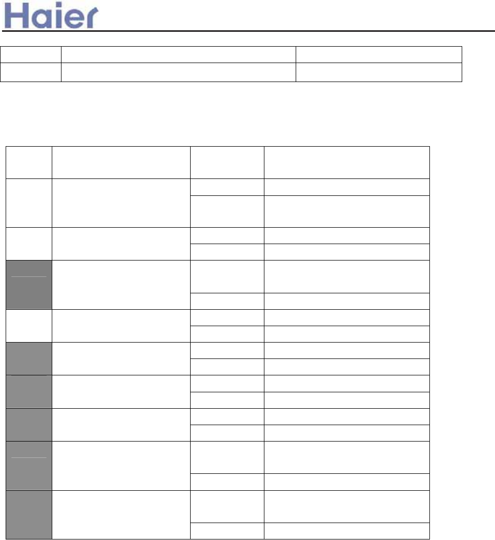
g Preset ̣̣̣
H Outdoor total capacity Actual value, decimal
In check mode, press [CHECK] to quit the check mode, and go into normal running
mode.
How to change the function switches?
No. Type State of
switch
Function description
Connected Central controller
J01 Changeover of Wired
controller and central
controller
Cut off Wired controller
Connected Set as simple controller
J02 Changeover of type of
wired controller Cut off Set as standard controller
Connected Use the sensor in the wired
controller
J06 Selection of room temp.
sensor
Cut off Use the sensor in the indoor unit
Connected Common control
J07 Auto restart after power
failure Cut off Auto restart after power failure
Connected Yes
J03 Display of room
temperature Cut off No
ON Set as slave controller
SW01
ķ
Changeover of master or
slave controller OFF Set as master controller
ON ̧
SW01
ĸ
ć or ̧
OFF ć
Connected Indoor unit in shorted time
function
D1 Shorten time function
Cut off Common control
Connected Send compulsorily defrost signal
to indoor unit
D2 Compulsorily defrost
Cut off Common control
Note: 1. The switches in grey can be operated after opening the cover of wired controller.
2. Switches or jumper wire must be adjusted when the wired controller is powered off. If the
wired controller is powered on, the above operations will be invalid.
3. Shorten time function
In normal operation, D1 is in short circuit, it will enter shorten time mode, and the time will be
shortened in the proportion of 60:1. In shorten time mode, LED will flash at the frequency of
0.5 second. Cut off D1, it will quit the shorten time mode and return to the normal operation
mode.
4. Compulsorily defrost
In heating mode 30ć and in High fan speed, D2 is in short circuit, it will enter compulsorily
defrost mode; cut off D2, it will quit. It is always be used when in testing to see if the defrost
function is good.
5. Lock function
>a__WcU[S^ <[c>a`V[e[a`Wc
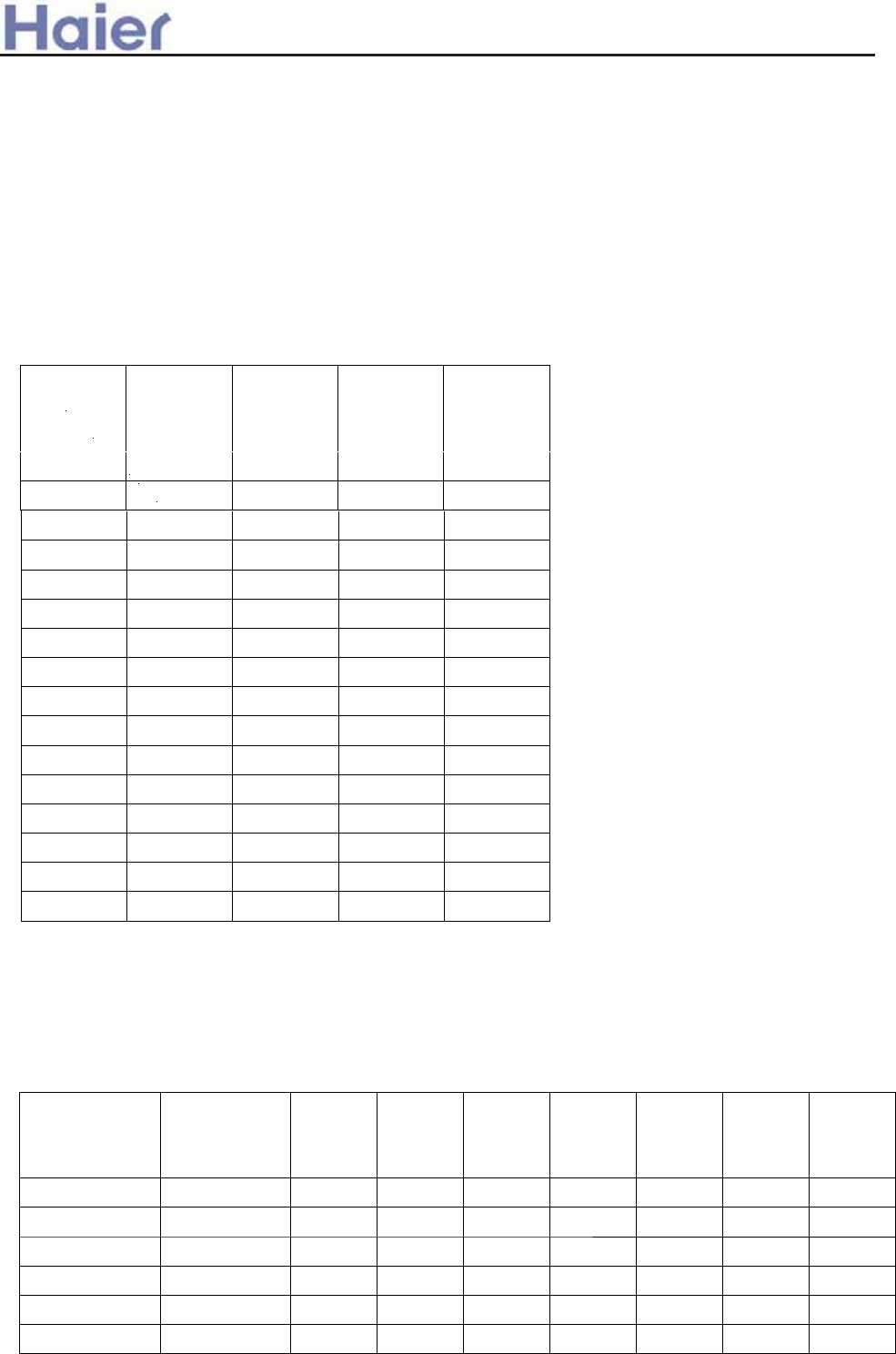
1
2
OFF OFF OFF ON
Setting address method:
The address setting can be realized by setting indoor PCB.
If you use the group control function, there should be a master unit and 15 sets of slave units.
For the master unit, the SW5-3 should be at “ON”. For the slave units, the SW5-3 should be
at “OFF”.
Please refer the below table,
>a__WcU[S^ <[c>a`V[e[a`Wc
There is no lock function only in the wired controller. But when it is connected with a central
controller, if the central controller is set to “central”, the buttons in the wired controller will be
invalid, or the buttons will be valid.
Indoor
unit
address
SW1-4 SW1-3 SW1-2 SW1-1
3
OFF OFF ON OFF
5
OFF ON OFF OFF
6
OFF ON OFF ON
7
OFF ON ON OFF
8
OFF ON ON ON
9
ON OFF OFF OFF
10
ON OFF OFF ON
11
ON OFF ON OFF
12
ON OFF ON ON
14
ON ON OFF ON
15
ON ON ON OFF
ON ON ON ON
If you use central control type, SW1, SW2 will be used simultaneously.
Wiring request in central control type: port A-B is connected with indoor port CN16˄A-B˅
through 2-core shield wire. Requirements:
1. Port A connects with port CN16˄A˅of all indoor units.
2. Port B connects with port CN16˄B˅of all indoor units.
Address on
central
controller
Indoor unit
address
SW2-3 SW2-2 SW2-1 SW1-4 SW1-3 SW1-2 SW1-1
1 1 OFF OFF OFF OFF OFF OFF OFF
2 2 OFF OFF OFF OFF OFF OFF ON
3 3 OFF OFF OFF OFF OFF ON OFF
4 4 OFF OFF OFF OFF OFF ON ON
5 5 OFF OFF OFF OFF ON OFF OFF
6 6 OFF OFF OFF OFF ON OFF ON
4
OFF OFF ON ON
13
ON ON OFF OFF

7 7 OFF OFF OFF OFF ON ON OFF
8 8 OFF OFF OFF OFF ON ON ON
9 9 OFF OFF OFF ON OFF OFF OFF
10 10 OFF OFF OFF ON OFF OFF ON
11 11 OFF OFF OFF ON OFF ON OFF
12 12 OFF OFF OFF ON OFF ON ON
13 13 OFF OFF OFF ON ON OFF OFF
14 14 OFF OFF OFF ON ON OFF ON
15 15 OFF OFF OFF ON ON ON OFF
16 16 OFF OFF OFF ON ON ON ON
17 17 OFF OFF ON OFF OFF OFF OFF
18 18 OFF OFF ON OFF OFF OFF ON
19 19 OFF OFF ON OFF OFF ON OFF
20 20 OFF OFF ON OFF OFF ON ON
>a__WcU[S^ <[c>a`V[e[a`Wc
21 21 OFF OFF ON OFF ON OFF OFF
22 22 OFF OFF ON OFF ON OFF ON
23 23 OFF OFF ON OFF ON ON OFF
24 24 OFF OFF ON OFF ON ON ON
25 25 OFF OFF ON ON OFF OFF OFF
26 26 OFF OFF ON ON OFF OFF ON
27 27 OFF OFF ON ON OFF ON OFF
28 28 OFF OFF ON ON OFF ON ON
29 29 OFF OFF ON ON ON OFF OFF
30 30 OFF OFF ON ON ON OFF ON
31 31 OFF OFF ON ON ON ON OFF
32 32 OFF OFF ON ON ON ON ON
33 33 OFF ON OFF OFF OFF OFF OFF
34 34 OFF ON OFF OFF OFF OFF ON
35 35 OFF ON OFF OFF OFF ON OFF
36 36 OFF ON OFF OFF OFF ON ON
37 37 OFF ON OFF OFF ON OFF OFF
38 38 OFF ON OFF OFF ON OFF ON
39 39 OFF ON OFF OFF ON ON OFF
40 40 OFF ON OFF OFF ON ON ON
41 41 OFF ON OFF ON OFF OFF OFF
42 42 OFF ON OFF ON OFF OFF ON
43 43 OFF ON OFF ON OFF ON OFF
44 44 OFF ON OFF ON OFF ON ON
45 45 OFF ON OFF ON ON OFF OFF
46 46 OFF ON OFF ON ON OFF ON
47 47 OFF ON OFF ON ON ON OFF
48 48 OFF ON OFF ON ON ON ON
49 49 OFF ON ON OFF OFF OFF OFF
50 50 OFF ON ON OFF OFF OFF ON

51 51 OFF ON ON OFF OFF ON OFF
52 52 OFF ON ON OFF OFF ON ON
53 53 OFF ON ON OFF ON OFF OFF
54 54 OFF ON ON OFF ON OFF ON
55 55 OFF ON ON OFF ON ON OFF
56 56 OFF ON ON OFF ON ON ON
57 57 OFF ON ON ON OFF OFF OFF
58 58 OFF ON ON ON OFF OFF ON
59 59 OFF ON ON ON OFF ON OFF
60 60 OFF ON ON ON OFF ON ON
61 61 OFF ON ON ON ON OFF OFF
62 62 OFF ON ON ON ON OFF ON
63 63 OFF ON ON ON ON ON OFF
>a__WcU[S^ <[c>a`V[e[a`Wc
64 64 OFF ON ON ON ON ON ON
65 65 ON OFF OFF OFF OFF OFF OFF
66 66 ON OFF OFF OFF OFF OFF ON
67 67 ON OFF OFF OFF OFF ON OFF
68 68 ON OFF OFF OFF OFF ON ON
69 69 ON OFF OFF OFF ON OFF OFF
70 70 ON OFF OFF OFF ON OFF ON
71 71 ON OFF OFF OFF ON ON OFF
72 72 ON OFF OFF OFF ON ON ON
73 73 ON OFF OFF ON OFF OFF OFF
74 74 ON OFF OFF ON OFF OFF ON
75 75 ON OFF OFF ON OFF ON OFF
76 76 ON OFF OFF ON OFF ON ON
77 77 ON OFF OFF ON ON OFF OFF
78 78 ON OFF OFF ON ON OFF ON
79 79 ON OFF OFF ON ON ON OFF
80 80 ON OFF OFF ON ON ON ON
81 81 ON OFF ON OFF OFF OFF OFF
82 82 ON OFF ON OFF OFF OFF ON
83 83 ON OFF ON OFF OFF ON OFF
84 84 ON OFF ON OFF OFF ON ON
85 85 ON OFF ON OFF ON OFF OFF
86 86 ON OFF ON OFF ON OFF ON
87 87 ON OFF ON OFF ON ON OFF
88 88 ON OFF ON OFF ON ON ON
89 89 ON OFF ON ON OFF OFF OFF
90 90 ON OFF ON ON OFF OFF ON
91 91 ON OFF ON ON OFF ON OFF
92 92 ON OFF ON ON OFF ON ON
93 93 ON OFF ON ON ON OFF OFF
94 94 ON OFF ON ON ON OFF ON

95 95 ON OFF ON ON ON ON OFF
96 96 ON OFF ON ON ON ON ON
97 97 ON ON OFF OFF OFF OFF OFF
98 98 ON ON OFF OFF OFF OFF ON
99 99 ON ON OFF OFF OFF ON OFF
100 100 ON ON OFF OFF OFF ON ON
101 101 ON ON OFF OFF ON OFF OFF
102 102 ON ON OFF OFF ON OFF ON
103 103 ON ON OFF OFF ON ON OFF
104 104 ON ON OFF OFF ON ON ON
105 105 ON ON OFF ON OFF OFF OFF
106 106 ON ON OFF ON OFF OFF ON
>a__WcU[S^ <[c>a`V[e[a`Wc
107 107 ON ON OFF ON OFF ON OFF
108 108 ON ON OFF ON OFF ON ON
109 109 ON ON OFF ON ON OFF OFF
110 110 ON ON OFF ON ON OFF ON
111 111 ON ON OFF ON ON ON OFF
112 112 ON ON OFF ON ON ON ON
113 113 ON ON ON OFF OFF OFF OFF
114 114 ON ON ON OFF OFF OFF ON
115 115 ON ON ON OFF OFF ON OFF
116 116 ON ON ON OFF OFF ON ON
117 117 ON ON ON OFF ON OFF OFF
118 118 ON ON ON OFF ON OFF ON
119 119 ON ON ON OFF ON ON OFF
120 120 ON ON ON OFF ON ON ON
121 121 ON ON ON ON OFF OFF OFF
122 122 ON ON ON ON OFF OFF ON
123 123 ON ON ON ON OFF ON OFF
124 124 ON ON ON ON OFF ON ON
125 125 ON ON ON ON ON OFF OFF
126 126 ON ON ON ON ON OFF ON
127 127 ON ON ON ON ON ON OFF
128 128 ON ON ON ON ON ON ON
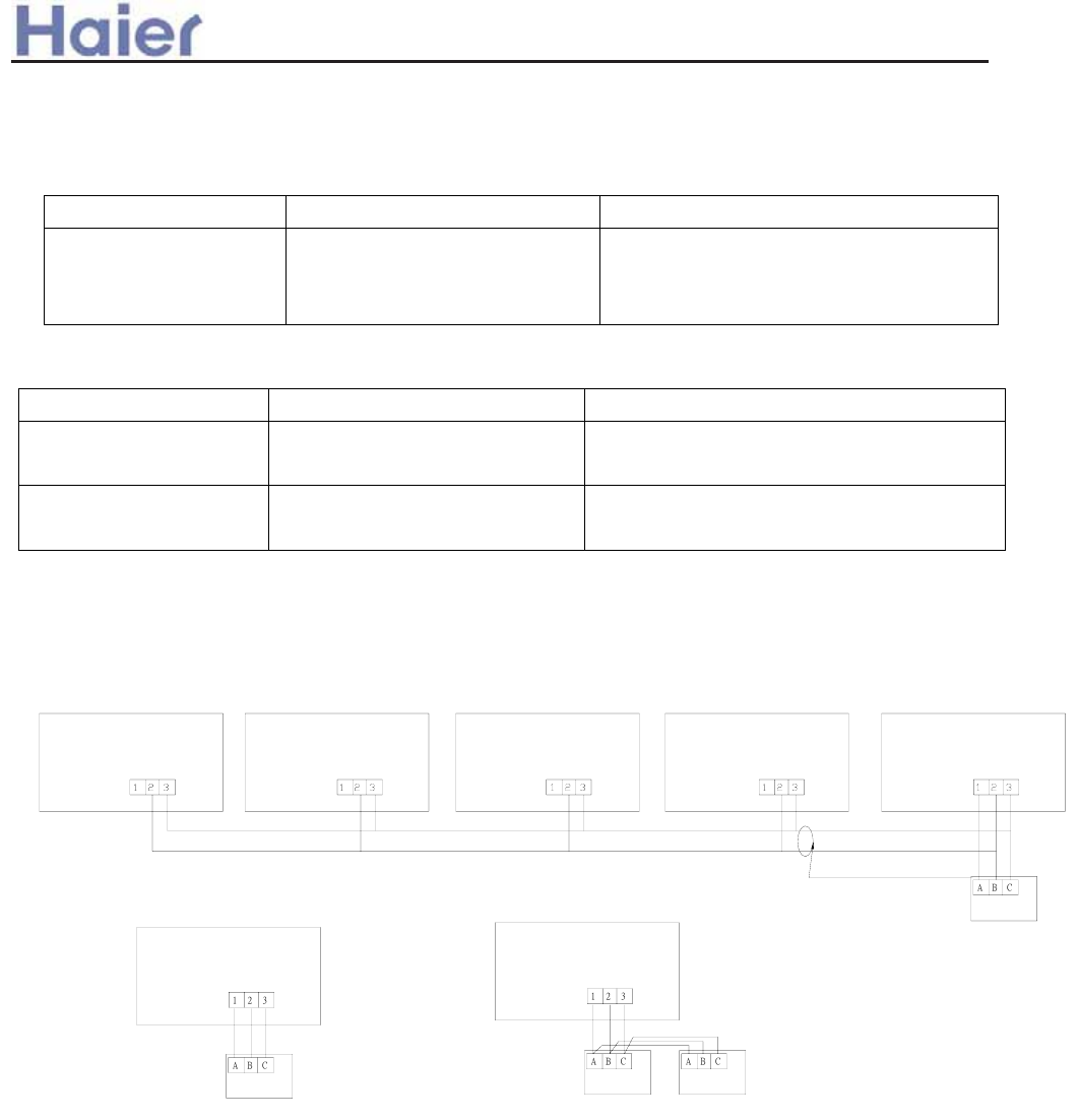
Electrical functions of wired controller:
1.Function difference between master wired controller and slave one:
Contrastive items Master wired controller Slave wired controller
Function All of functions Only with below functions:
ON/OFF, MODE, FAN SPEED,
SET TEMP., SWING
2. Function difference between simple wired controller and the standard one:
Contrastive item Standard wired controller Simple wired controller
Function With all functions Only can control ON/OFF, MODE,
FAN, TEMP.,SWING.
Master/Slave
selection
Can be either of Master
and Slave controller
Only can be Master controller
3. Wiring connections of wired controller:
indoor N
wired controller
indoor 1 indoor 2
indoor 1
indoor 16
control wiring of wired controller, polar.
indoor 15
wired controller wired controller wired controller
wired controller wired controller
wired controller
wired controller
indoor 1
wired controller wired controller wired controller
A
BC
(master unit)
polar wire polar wire
polar wire
There are three methods to connection wired controller and the indoor units:
A. One wired controller can control max. up to 16 sets of indoor units, and 3
pieces of polar wire must connect the wired controller and the master unit (the
indoor unit connected with wired controller directly), the others connect with
the master unit through 2 pieces of polar wire.
B. One wired controller controls one indoor unit, and the indoor unit connects
with the wired controller through 3 pieces of polar wire.
C. Two wired controllers control one indoor unit. The wired controller
>a__WcU[S^ <[c>a`V[e[a`Wc
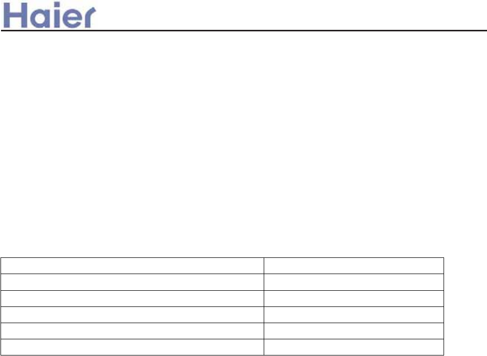
connected with indoor unit is called master one, the other is called slave one.
Master wired controller and indoor unit; master and slave wired controllers are
all connected through 3 pieces of polar wire.
3. Communication wiring:
The wired controller is equipped with special communication wiring in the
accessories. 3-core terminal (1-white 2-yellow 3-red) is connected with the
terminal AǃBǃC of wired controller respectively.
The communication wiring is 4 meter long; if the actual length is more than it,
please distribute wiring according to below table:
Communication wiring length˄m˅Dimensions of wiring
<100 0.3mm2X3-core shielded wire
ı100 and <200 0.5mm2X3-core shielded wire
ı200 and <300 0.75mm2X3-core shielded wire
ı300 and <400 1.25mm2X3-core shielded wire
ı400 and <600 2mm2X3-core shielded wire
ĆOne side of the shielded sheet of communication wire must be earthed.
>a__WcU[S^ <[c>a`V[e[a`Wc
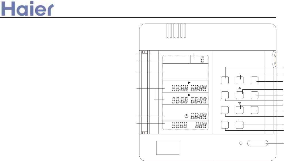
5 - Time display area-including display the weekday, hour and minute; before setting timing function,
please calibrate the current clock.
6 - Unit number trouble code display area-when the air conditioner in the control network has trouble,
the corresponding unit number and the trouble code will display in this area.
7 - Program
Enter or exit the timing setting in normal condition,
8 - Holiday
Close the units and invalid for timing in no affect on the timing setting condition.
9 - Number
Group setting and timing setting (take one day as a standard unit)
10 - Hour
Timing setting condition and time setting condition ,select the adjustment
11 - Min.
Timing setting condition and time setting condition ,select the adjustment
12 - Time
Enter and exit the at present date and time condition in normal condition
13 - Week
Timing setting condition and time setting condition ,select the adjustment
14 -Timing setting condition and time setting condition , increase the setting parameters
15 -Timing setting condition and time setting condition , decrease the setting parameters
16 - Cancel
Cancel the present setting before confirm the parameter.
17 - Confirm Confirm the parameter.
18 - ON/OFF Open/close the unit.
OFF OFF OFF OFF OFF OFF OFF
1 2 3 4 5 6 7
MON TUE WED THU FRI SAT SUN
ON ON ON ON ON ON ON
MON TUE WED THU FRI SAT SUN
Week
Time
Min.
HolidayProgram
Hour Cancel
Confirm
Number
ON/OFF
PROGRAM NO.
1 2 3 4 5 6 7
SET 1 ON OFF
SET 2 ON OFF
NO.
2
1
3
4
5
6
7
8
9
14
16
10
15
17
11
13
12
18
Instruction:
1 - PROGRAM-the display shows the weekly
timer timing setting state, and in setting state,
the timing information can be adjusted.
2 - No:8-timing group number: when it is not
set timing, there is no timing group number;
after setting timing, it will automatically form
a group number according to each kind of
setting combination, so that in the sequent
timing setting, it can execute instant setting
by using timing group number.
3 - Setting state and holiday functional area-1 (MON), 2 (TUE), 3 (WED), 4 (THU), 5 (FRI), 6 (SAT), 7 (SUN)
are used to indicate the 7 days in a week; the symbol of this part will display after powered on; after set the
corresponding weekday's timing function, the ON symbol under the corresponding symbol will display, if
not set timing, there will be no display; if not set Holiday function, the OFF symbol on the upside of the
indicating symbol will not display, after set Holiday function, the OFF will display and at the same time
temporarily the previous timing setting and turn off the air conditioner.
4 - No. 1 group and No.2 group timing setting display area-when entering timing setting state, the contents
of timing will flash; choose Date, Hour and Minute to perform increase and decrease adjustment by the
adjusting key.
>a__WcU[S^ <[c>a`V[e[a`Wc
3. Weekly timer YCS-A001
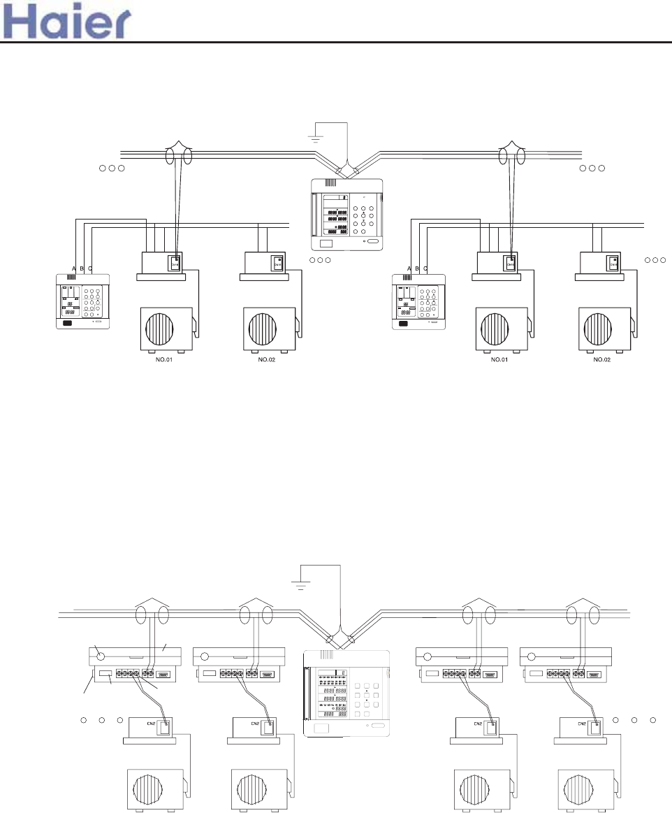
1. Use group controller and weekly timer to realize the group control function + weekly timing function, applicable for the units except
for the unit which needs detector to realize the weekly timer function, such as cabinet type, console type.
Connecting method
C
HEALTH
F
MODE FAN SWING
TEMP
CLOCK
TIMER SET RECOVERY
CHECK FILTER RESET
MODE FAN
AUTO AUTO
FAN ONLY
COOL
DRY
HEAT
TES
HIGH
MED
LOW
FIX
CENTRAL
OPERATION
STANDBY
PRE-HEAT
DEFROST
FILTER
HEALTH CHECK SWING
UNIT NO. DEMAND MANUAL
CEN.ADD.
SYS.ADD.
ROOM TEMP.
SET TEMP.
TIMER CLOCK UP DOWN VENTILATION
ON
OFF
DAILY
AUTO
RECOVERY
NORMAL
ON/OFF
123
CN5 123
CN5 123
CN5 123
CN5
OFF OFF OFF OFF OFF OFF OFF
MON TUE WED THU FRI SAT SUN
ON ON ON ON ON ON ON
MON TUE WED THU FRI SAT SUN
Program Holiday Number
Hour Cancel
Min. Confirm
Time Week
Haier R
Power cord
Power on/off
View of the detector interface
Indoor unit
Outdoor unit
Air Conditoner HMI
Resetting
Week
Time
Min.
HolidayProgram
Hour Cancel
Confirm
Number
ON/OFF
PROGRAM NO.
1 2 3 4 5 6 7
1 2 3 4 5 6 7
SET 1 ON OFF
SET 2 ON OFF
NO.
2. Use weekly timer to realize weekly timing function,applicable for the units which need detector to realize the weekly timer function,
such as cabinet type, console type.
The detector is connected with one air conditioner by the 4-core screw fixed terminals A+ and A- of air conditioner interface, then
accordingly set the dial-code switch of the detector in single unit working mode; the address number setting shall be performed according
the planned program, for specific setting and corresponding address, please refer to the dial-code switch setting in detector's operation
manual; use weekly timer to fulfill weekly timing function, the system needs to be connected with weekly timer; each detector and weekly
timer is connected with shielded twisted pair communication bus by the 2-core screw fixed terminals (A and B) of its RS-485 interface;
the communication bus must be shielded and grounded, and the resistors in its two ends shall be suited.
3. Use weekly timer to realize two units auto-changeover function,applicable for the units which need detector to realize the weekly
timer function, such as cabinet type, console type.
The detector is connected with two same model air conditioners by the 4-core screw fixed terminals of air conditioner interface; then
accordingly set the dial-code switch of the detector in double units working mode, and the double units switch time is default 24 hours;
the address number setting shall be performed according the planned program, for specific setting and corresponding address, please
refer to the dial-code switch setting in detector's operation manual; use weekly timer to fulfill double units switch weekly timing function,
the system needs to be connected with weekly timer; each detector and weekly timer is connected with shielded twisted pair communication
bus by the 2-core screw fixed terminals (A and B) of its RS-485 interface; the communication bus must be shielded and grounded, and
the resistors in its two ends shall be suited.
>a__WcU[S^ <[c>a`V[e[a`Wc
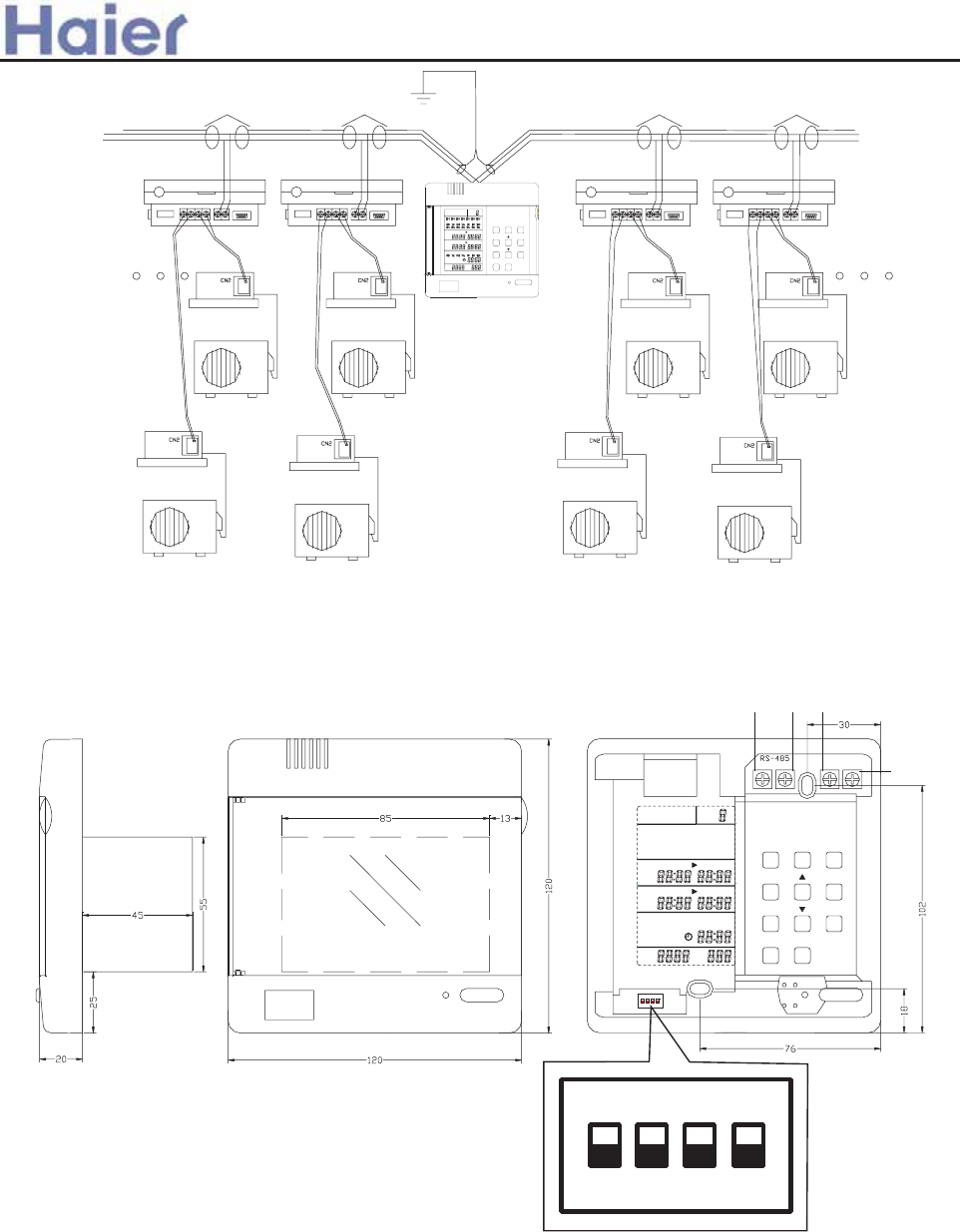
Installation dimensions
OFF OFF OFF OFF OFF OFF OFF
1 2 3 4 5 6 7
MON TUE WED THU FRI SAT SUN
ON ON ON ON ON ON ON
MON TUE WED THU FRI SAT SUN
ON.
1 2 3 4
Week
Time
Min.
HolidayProgram
Hour Cancel
Confirm
Number
PROGRAM NO.
1 2 3 4 5 6 7
SET 1 ON OFF
SET 2 ON OFF
NO.
BA
12VDC
O
RS-485
Week
Time
Min.
HolidayProgram
Hour Cancel
Confirm
Number
ON/OFF
PROGRAM NO.
1 2 3 4 5 6 7
1 2 3 4 5 6 7
SET 1 ON OFF
SET 2 ON OFF
NO.
>a__WcU[S^ <[c>a`V[e[a`Wc
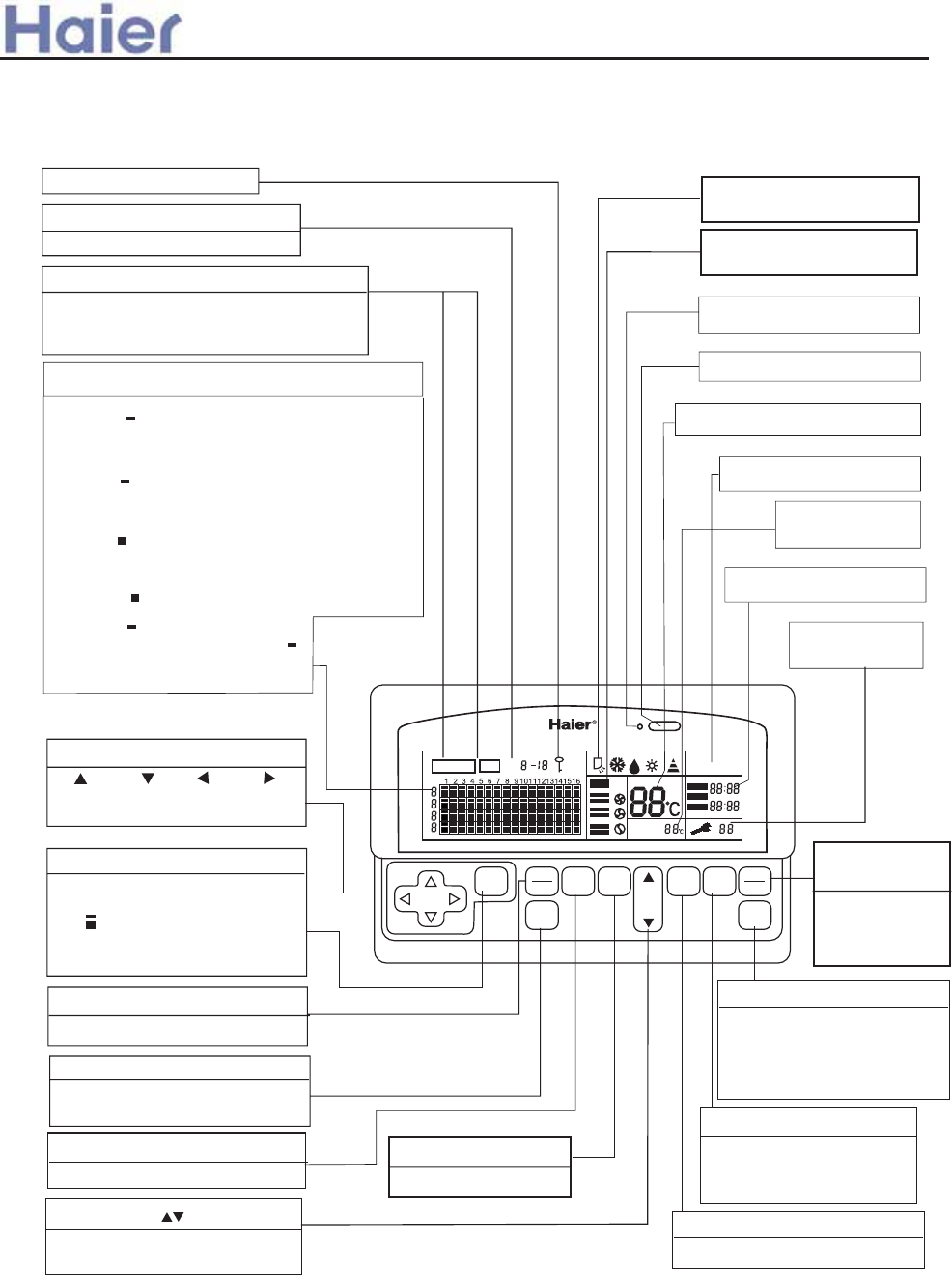
MONITERSET
UNIT
AUTO
TEMP
ROOM
TEMP
CENTRAL
REMOTE
TIMER ON
EVERY DAY
SELECT
ON
OFF MODE FAN
TEMP.
TIME
TIME TIMER
CENTRAL
REMOTE
CONFIRM
LOCK
TIMER OFF
Display of operation mode
and signal emitting
LOCK display
Display of current unit number
Location of the indicating cursor
Display of MONI/SET
Generally indicating "MONI". When
setting ON/OFF or other items, it
changes from "MONI" into "SET".
Display of the connected units
Flashing indicates the cursor for current unit
or that the monitor and air conditioner are in
group selection status.
Lighted indicates the monitor for the unit
has been linked into the network, otherwise not
linked.
Lighted
indicates the unit is in "on" mode, otherwise
in"off" mode.
Flashing indicates fault.
Flashing of the current unit
indicates the cursor, flashing
of non-current unit indicates the
unit is in group selection status.
Direction keys
Up Down Left Right
Used to select the current unit
number
SELECT key
To determine the selected unit
number during group selection,
the of the corresponding
unit number flashes at the same
time.
LOCK key
This key can be used to lock the
keys and LCD display.
ON/OFF key
Used to select unit on/off.
MODE key
Used to select running mode.
Display of fan speed and
louver
Total on/ Total off indicator
Total on/ Total off key
Display of temperature setting
FAN SPEED key
To select the fan speed.
Note: In MONI mode, pressing SEL, MODE, FAN SPEED, TEMP TIME keys may change the MONI mode into
SET mode. If SET key or other keys hasn't been pressed within 10s, it will automatically return to MONI mode.
TEMP/TIME keys
Used to set a desired room
temperature, clock and time.
CLOCK key
Used to unitarily set the clock.
TIMER key
To select timer mode:
TIMER ON/TIMER OFF
/blank
CONFIRM key
Used to confirm the function
settings and send to the air
conditioner corresponding to
the selected unit number.
CENTRAL/
REMOTE key
To select central
or remote control
method.
Display of
self-check code
Display of time setting
Display of CENT/REM
Display of room
temperature
Total on/Total off
Function description:
>a__WcU[S^ <[c>a`V[e[a`Wc
4.
Central Controller YCZ-A001
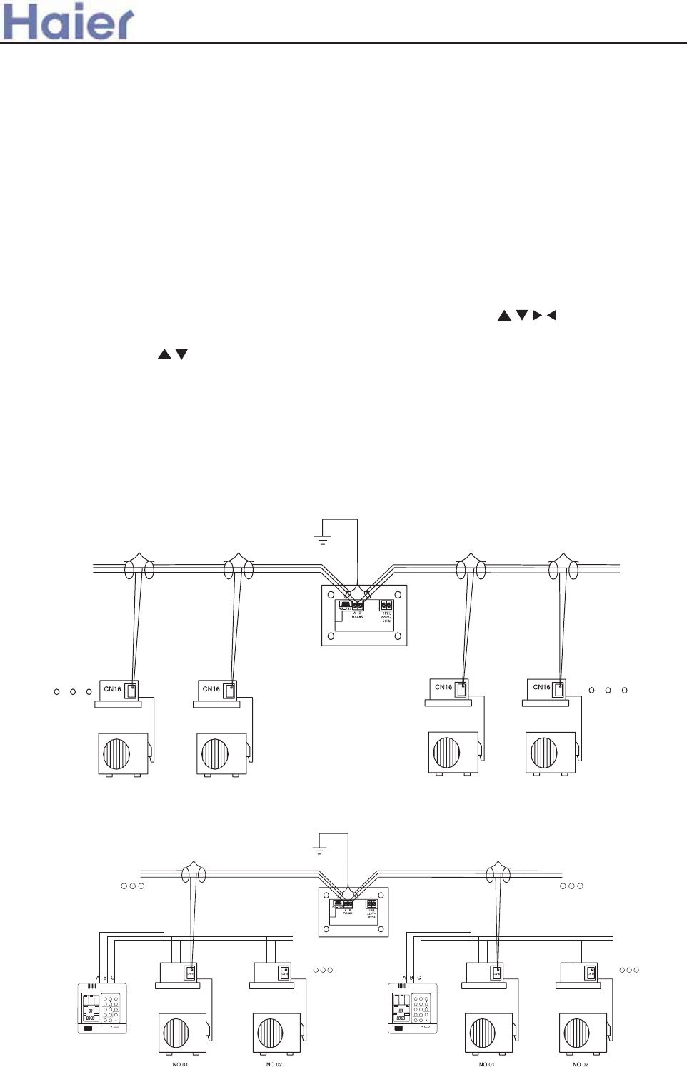
6. Central control system + Group control system(max.128 x16 indoor units can be connected),this type is
applicable for the unitary free indoor units except for cabinet type.
1. Communication function
Communicate with the indoor PCB in the group control network
To communicate with the indoor PCB through the R S-485 bus (A, B). The central controller sends commands
to and receives response from indoor PCB; communication by address enables sending and receiving control
information, work information and fault information between indoor PCB and the central controller.
2. LCD display function:
The LCD could display the fundamental status of air conditioning units (are the units existing? On/off? Fault?
Are units group selected? Cursor and the current unit no.);
The LCD can display the working status of the air conditioning unit with the current number (mode, fan speed,
temperature setting, room temperature,timer,error code, central/remote control status);
The working status of the central controller (monitor/set status, panel locking status, signaling status).
3. Key input function:
The key for locking key function of the central controller: LOCK.
4. Unit number setting function:
To enrich the control functions of Haier commercial air conditioner remote monitoring system, multiple controllers
could be set to work together for a combination of multiple functions. For this, the central controller is provided
with a two-digital switch for setting controller address.
5. Realizing central control function with the central controller
(max.128 indoor units can be connected)
this type is applicable for the unitary free indoor units except for cabinet type.
The keys for moving the current unit number cursor and for group selection: , , , , SELECT;
The keys for setting working status of the air conditioning unit and control conditions: ON/OFF, MODE, FAN
SPEED, TEMP, TIME / , CLOCK,TIMER, CENT/REM, SET;
indoor
outdoor
C
HEALTH
F
MODE FAN SWING
TEMP
CLOCK
TIMER SET RECOVERY
CHECK FILTER RESET
MODE FAN
AUTO AUTO
FAN ONLY
COOL
DRY
HEAT
TES
HIGH
MED
LOW
FIX
CENTRAL
OPERATION
STANDBY
PRE-HEAT
DEFROST
FILTER
HEALTH CHECK SWING
UNIT NO. DEMAND MANUAL
CEN.ADD.
SYS.ADD.
ROOM TEMP.
SET TEMP.
TIMER CLOCK UP DOWN VENTILATION
ON
OFF
DAILY
AUTO
RECOVERY
NORMAL
ON/OFF
123 123
CN5 CN5 123
CN5 123
CN5
>a__WcU[S^ <[c>a`V[e[a`Wc
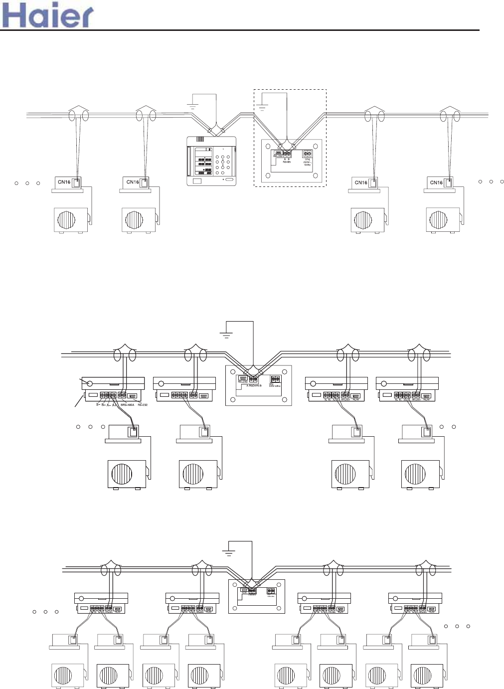
7. Use central controller + weekly timer to realize the group control function + weekly timing function,
this type is applicable for the unitary free indoor units except for cabinet type.
OFF OFF OFF OFF OFF OFF OFF
MON TUE WED THU FRI SAT SUN
ON ON ON ON ON ON ON
MON TUE WED THU FRI SAT SUN
Program Holiday Number
Hour Cancel
Min. Confirm
Time Week
Haier R
CN2 CN2 CN2 CN2
RS-485 bus Upper A Lower B
Rear view of the
central controller
View of the detector
Power cord
Power on/off
Indoor unit
Outdoor unit
CN2 CN2 CN2 CN2 CN2 CN2 CN2 CN2
9.Realizing double unit switch-over group control function with the centralcontroller, for the unit which
needs the detector, such as cosole unit, cabinet units.
8. Realizing group control function with the central controller, for the unit which needs the detector, such
as cosole unit, cabinet units.
>a__WcU[S^ <[c>a`V[e[a`Wc
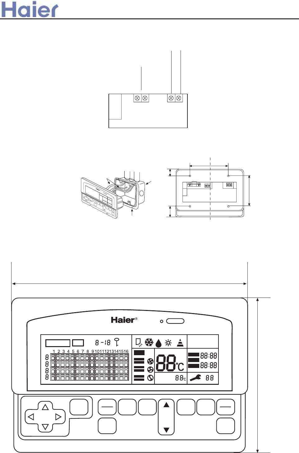
(Fig.1)
180mm
120mm
MONITER SET UNIT
AUTO
TEMP
ROOM
TEMP
CENTRAL REMOTE
TIMER ON
EVERY DAY
SELECT
ON
OFF MODE FAN
TEMP.
TIME
TIME TIMER CENTRAL
REMOTE
CONFIRM
LOCK
TIMER OFF
Total on/Total off
Exterior dimension
1PH , 220-240V~, 50Hz
Installation procedure
1. Wire connecting
RS - 232 AB
Power supply
To connect the process
control monitor/
detector
To connect the
computer or MODEM
2. Installation method
A wiring box cover must be used.
The central controller shall be installed into the installation box built in the wall fastening with 4 screws (as shown).
Note: Please confirm the supply voltage of AC220-240V and correct wiring. In application environment with intense
electromagnetic interference, the central controller should be shielded, while the connecting wire between the monitor
and the central controller should be shielded twin twisted wire.
RS - 485
Total on/Total off
SELECT ON
OFF MODE FAN
TEMP.
TIME
TIME TIMER
CENTER
CONTROL
CONFIRM
LOCK
91.5mm
15mm19mm
86mm
Rear view
>a__WcU[S^ <[c>a`V[e[a`Wc
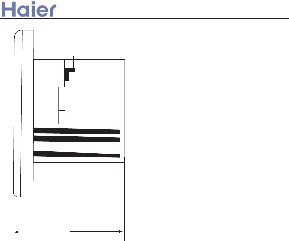
(Fig.2)
As illustrated:
(Figure 1 is the front view and Figure 2
is the side view) The central controller
is 180mm long, 120mm wide and 64.4 mm
thick.
64.4mm
>a__WcU[S^ <[c>a`V[e[a`Wc
