Haier R410A 0000001653 User Manual To The Fafb00f1 4123 49b3 A856 717a53959ad0
User Manual: Haier R410A to the manual
Open the PDF directly: View PDF ![]() .
.
Page Count: 414 [warning: Documents this large are best viewed by clicking the View PDF Link!]
ii
HWE09080 GB
Safety Precautions
Before installing the unit, thoroughly read the following safety precautions.
Observe these safety precautions for your safety.
WARNING
This symbol is intended to alert the user to the presence of important instructions that must be followed to avoid
the risk of serious injury or death.
CAUTION
This symbol is intended to alert the user to the presence of important instructions that must be followed to avoid
the risk of serious injury or damage to the unit.
After reading this manual, give it to the user to retain for future reference.
Keep this manual for easy reference. When the unit is moved or repaired, give this manual to those who provide these
services.
When the user changes, make sure that the new user receives this manual.
WARNING
Ask your dealer or a qualified technician to install the
unit.
Improper installation by the user may result in water leak-
age, electric shock, smoke, and/or fire.
Properly install the unit on a surface that can with-
stand the weight of the unit.
Unit installed on an unstable surface may fall and cause in-
jury.
Only use specified cables. Securely connect each ca-
ble so that the terminals do not carry the weight of the
cable.
Improperly connected or fixed cables may produce heat
and start a fire.
Take appropriate safety measures against strong
winds and earthquakes to prevent the unit from falling.
If the unit is not installed properly, the unit may fall and
cause serious injury to the person or damage to the unit.
Do not make any modifications or alterations to the
unit. Consult your dealer for repair.
Improper repair may result in water leakage, electric shock,
smoke, and/or fire.
Do not touch the heat exchanger fins.
The fins are sharp and dangerous.
In the event of a refrigerant leak, thoroughly ventilate
the room.
If refrigerant gas leaks and comes in contact with an open
flame, poisonous gases will be produced.
When installing the All-Fresh type units, take it into
consideration that the outside air may be discharged
directly into the room when the thermo is turned off.
Direct exposure to outdoor air may have an adverse effect
on health. It may also result in food spoilage.
Properly install the unit according to the instructions
in the installation manual.
Improper installation may result in water leakage, electric
shock, smoke, and/or fire.
Have all electrical work performed by an authorized
electrician according to the local regulations and in-
structions in this manual, and a dedicated circuit must
be used.
Insufficient capacity of the power supply circuit or improper
installation may result in malfunctions of the unit, electric
shock, smoke, and/or fire.
ii
HWE09080 GB
WARNING
Securely attach the terminal block cover (panel) to the
unit.
If the terminal block cover (panel) is not installed properly,
dust and/or water may infiltrate and pose a risk of electric
shock, smoke, and/or fire.
Only use the type of refrigerant that is indicated on the
unit when installing or reinstalling the unit.
Infiltration of any other type of refrigerant or air into the unit
may adversely affect the refrigerant cycle and may cause
the pipes to burst or explode.
When installing the unit in a small room, exercise cau-
tion and take measures against leaked refrigerant
reaching the limiting concentration.
Consult your dealer with any questions regarding limiting
concentrations and for precautionary measures before in-
stalling the unit. Leaked refrigerant gas exceeding the lim-
iting concentration causes oxygen deficiency.
Consult your dealer or a specialist when moving or re-
installing the unit.
Improper installation may result in water leakage, electric
shock, and/or fire.
After completing the service work, check for a gas
leak.
If leaked refrigerant is exposed to a heat source, such as a
fan heater, stove, or electric grill, poisonous gases may be
produced.
Do not try to defeat the safety features of the unit.
Forced operation of the pressure switch or the temperature
switch by defeating the safety features of these devices, or
the use of accessories other than the ones that are recom-
mended by MITSUBISHI may result in smoke, fire, and/or
explosion.
Only use accessories recommended by MITSUBISHI.
Ask a qualified technician to install the unit. Improper instal-
lation by the user may result in water leakage, electric
shock, smoke, and/or fire.
Control box houses high-voltage parts.
When opening or closing the front panel of the control box,
do not let it come into contact with any of the internal com-
ponents. Before inspecting the inside of the control box,
turn off the power, keep the unit off for at least 10 minutes,
and confirm that the voltage between FT-P and FT-N on
INV Board has dropped to DC20V or less. (It takes about
10 minutes to discharge electricity after the power supply is
turned off.)
iiiiii
HWE09080 GB
Precautions for handling units for use with R410A
CAUTION
Do not use the existing refrigerant piping.
A large amount of chlorine that is contained in the residual
refrigerant and refrigerator oil in the existing piping may
cause the refrigerator oil in the new unit to deteriorate.
R410A is a high-pressure refrigerant and can cause the
existing pipes to burst.
Use refrigerant pipes made of phosphorus deoxidized
copper. Keep the inner and outer surfaces of the pipes
clean and free of such contaminants as sulfur, oxides,
dust, dirt, shaving particles, oil, and water.
These types of contaminants inside the refrigerant pipes
may cause the refrigerant oil to deteriorate.
Store the pipes to be installed indoors, and keep both
ends of the pipes sealed until immediately before braz-
ing. (Keep elbows and other joints wrapped in plastic.)
Infiltration of dust, dirt, or water into the refrigerant system
may cause the refrigerating machine oil to deteriorate or
cause the unit to malfunction.
Use a small amount of ester oil, ether oil, or alkylben-
zene to coat flares and flanges.
Infiltration of a large amount of mineral oil may cause the re-
frigerating machine oil to deteriorate.
Charge liquid refrigerant (as opposed to gaseous re-
frigerant) into the system.
If gaseous refrigerant is charged into the system, the com-
position of the refrigerant in the cylinder will change and
may result in performance loss.
Use a vacuum pump with a reverse-flow check valve.
If a vacuum pump that is not equipped with a reverse-flow
check valve is used, the vacuum pump oil may flow into the
refrigerant cycle and cause the refrigerating machine oil to
deteriorate.
Prepare tools for exclusive use with R410A. Do not use
the following tools if they have been used with the con-
ventional refrigerant (gauge manifold, charging hose,
gas leak detector, reverse-flow check valve, refrigerant
charge base, vacuum gauge, and refrigerant recovery
equipment.).
If the refrigerant or the refrigerating machine oil left on
these tools are mixed in with R410A, it may cause the re-
frigerating machine oil to deteriorate.
Infiltration of water may cause the refrigerating machine
oil to deteriorate.
Gas leak detectors for conventional refrigerants will not
detect an R410A leak because R410A is free of chlorine.
Do not use a charging cylinder.
If a charging cylinder is used, the composition of the refrig-
erant will change, and the unit may experience power loss.
Exercise special care when handling the tools for use
with R410A.
Infiltration of dust, dirt, or water into the refrigerant system
may cause the refrigerating machine oil to deteriorate.
Only use refrigerant R410A.
The use of other types of refrigerant that contain chlorine
(i.e. R22) may cause the refrigerating machine oil to deteri-
orate.
iv
HWE09080 GB
Before installing the unit
WARNING
Do not install the unit where a gas leak may occur.
If gaseous refrigerant leaks and piles up around the unit, it
may be ignited.
Do not use the unit to keep food items, animals, plants,
artifacts, or for other special purposes.
The unit is not designed to preserve food products.
Do not use the unit in an unusual environment.
Do not install the unit where a large amount of oil or steam
is present or where acidic or alkaline solutions or chemical
sprays are used frequently. Doing so may lead to a re-
markable drop in performance, electric shock, malfunc-
tions, smoke, and/or fire.
The presence of organic solvents or corrosive gas (i.e.
ammonia, sulfur compounds, and acid) may cause gas
leakage or water leakage.
When installing the unit in a hospital, take appropriate
measures to reduce noise interference.
High-frequency medical equipment may interfere with the
normal operation of the air conditioner or vice versa.
Do not install the unit on or over things that cannot get
wet.
When the humidity level exceeds 80% or if the drainage
system is clogged, the indoor unit may drip water. Drain wa-
ter is also discharged from the heat source unit. Install a
centralized drainage system if necessary.
vv
HWE09080 GB
Before installing the unit (moving and reinstalling the unit) and performing
electrical work
CAUTION
Properly ground the unit.
Do not connect the grounding wire to a gas pipe, water pipe,
lightning rod, or grounding wire from a telephone pole. Im-
proper grounding may result in electric shock, smoke, fire,
and/or malfunction due to noise interference.
Do not put tension on the power supply wires.
If tension is put on the wires, they may break and result in
excessive heat, smoke, and/or fire.
Install an earth leakage breaker to avoid the risk of
electric shock.
Failure to install an earth leakage breaker may result in
electric shock, smoke, and/or fire.
Use the kind of power supply wires that are specified
in the installation manual.
The use of wrong kind of power supply wires may result in
current leak, electric shock, and/or fire.
Use breakers and fuses (current breaker, remote
switch <switch + Type-B fuse>, moulded case circuit
breaker) with the proper current capacity.
The use of wrong capacity fuses, steel wires, or copper
wires may result in malfunctions, smoke, and/or fire.
Do not spray water on the air conditioner or immerse
the air conditioner in water.
Otherwise, electric shock and/or fire may result.
When handling units, always wear protective gloves to
protect your hands from metal parts and high-tempera-
ture parts.
Periodically check the installation base for damage.
If the unit is left on a damaged platform, it may fall and
cause injury.
Properly install the drain pipes according to the in-
structions in the installation manual. Keep them insu-
lated to avoid dew condensation.
Improper plumbing work may result in water leakage and
damage to the furnishings.
Exercise caution when transporting products.
Products weighing more than 20 kg should not be carried
alone.
Do not carry the product by the PP bands that are used on
some products.
Do not touch the heat exchanger fins. They are sharp and
dangerous.
When lifting the unit with a crane, secure all four corners
to prevent the unit from falling.
Properly dispose of the packing materials.
Nails and wood pieces in the package may pose a risk of
injury.
Plastic bags may pose a risk of choking hazard to chil-
dren. Tear plastic bags into pieces before disposing of
them.
vi
HWE09080 GB
Before the test run
CAUTION
Turn on the unit at least 12 hours before the test run.
Keep the unit turned on throughout the season. If the unit is
turned off in the middle of a season, it may result in malfunc-
tions.
To avoid the risk of electric shock or malfunction of the
unit, do not operate switches with wet hands.
Do not touch the refrigerant pipes with bare hands dur-
ing and immediately after operation.
During or immediately after operation, certain parts of the
unit such as pipes and compressor may be either very cold
or hot, depending on the state of the refrigerant in the unit
at the time. To reduce the risk of frost bites and burns, do
not touch these parts with bare hands.
Do not operate the unit without panels and safety
guards.
Rotating, high-temperature, or high-voltage parts on the unit
pose a risk of burns and/or electric shock.
Do not turn off the power immediately after stopping
the operation.
Keep the unit on for at least five minutes before turning off
the power to prevent water leakage or malfunction.
Do not operate the unit without the air filter.
Dust particles may build up in the system and cause mal-
functions.

CONTENTS
HWE09080 GB
I
Read Before Servicing
[1] Read Before Servicing.............................................................................................................. 3
[2] Necessary Tools and Materials ................................................................................................ 4
[3] Piping Materials ........................................................................................................................ 5
[4] Storage of Piping ...................................................................................................................... 7
[5] Pipe Processing........................................................................................................................ 7
[6] Brazing...................................................................................................................................... 8
[7] Air Tightness Test..................................................................................................................... 9
[8] Vacuum Drying (Evacuation) ..................................................................................................10
[9] Refrigerant Charging .............................................................................................................. 12
[10] Remedies to be taken in case of a Refrigerant Leak............................................................ 12
[11] Characteristics of the Conventional and the New Refrigerants ............................................ 13
[12] Notes on Refrigerating Machine Oil...................................................................................... 14
II
Restrictions
[1] System configuration .............................................................................................................. 17
[2] Types and Maximum allowable Length of Cables .................................................................. 18
[3] Switch Settings and Address Settings .................................................................................... 19
[4] Sample System Connection ................................................................................................... 26
[5] An Example of a System to which an MA Remote Controller is connected ........................... 27
[6] An Example of a System to which an ME Remote Controller is connected ........................... 49
[7] An Example of a System to which both MA Remote Controller and
ME Remote Controller are connected .................................................................................... 53
[8] Restrictions on Pipe Length.................................................................................................... 58
III
Heat source Unit Components
[1] Heat source Unit Components and Refrigerant Circuit........................................................... 75
[2] Control Box of the Heat source Unit ....................................................................................... 78
[3] Heat source Unit Circuit Board ............................................................................................... 81
[4] BC Controller Components..................................................................................................... 88
[5] Control Box of the BC Controller ............................................................................................91
[6] BC Controller Circuit Board .................................................................................................... 92
IV
Remote Controller
[1] Functions and Specifications of MA and ME Remote Controllers .......................................... 97
[2] Group Settings and Interlock Settings via the ME Remote Controller .................................... 98
[3] Interlock Settings via the MA Remote Controller .................................................................. 102
[4] Using the built-in Temperature Sensor on the Remote Controller........................................ 103
V
Electrical Wiring Diagram
[1] Electrical Wiring Diagram of the Heat source Unit................................................................ 107
[2] Electrical Wiring Diagram of the BC Controller..................................................................... 111
[3] Electrical Wiring Diagram of Transmission Booster.............................................................. 120
VI
Refrigerant Circuit
[1] Refrigerant Circuit Diagram .................................................................................................. 123
[2] Principal Parts and Functions ............................................................................................... 126
VII
Control
[1] Functions and Factory Settings of the Dipswitches .............................................................. 137
[2] Controlling the Heat source Unit........................................................................................... 143
[3] Controlling BC Controller ...................................................................................................... 160
[4] Operation Flow Chart............................................................................................................ 161
VIII
Test Run Mode
[1] Items to be checked before a Test Run................................................................................ 175
[2] Test Run Method .................................................................................................................. 176
[3] Operating Characteristic and Refrigerant Amount................................................................ 177
[4] Adjusting the Refrigerant Amount......................................................................................... 177
[5] Refrigerant Amount Adjust Mode.......................................................................................... 182
[6] The following symptoms are normal. .................................................................................... 186
[7] Standard Operation Data (Reference Data) ......................................................................... 187

CONTENTS
HWE09080 GB
IX
Troubleshooting
[1] Error Code Lists.................................................................................................................... 227
[2] Responding to Error Display on the Remote Controller........................................................ 230
[3] Investigation of Transmission Wave Shape/Noise ............................................................... 303
[4] Troubleshooting Principal Parts............................................................................................ 306
[5] Refrigerant Leak ................................................................................................................... 343
[6] Compressor Replacement Instructions................................................................................. 347
[7] Servicing the BC controller ................................................................................................... 353
[8] Troubleshooting Using the Heat source Unit LED Error Display .......................................... 356
X
LED Monitor Display on the Heat source Unit Board
[1] How to Read the LED on the Service Monitor ...................................................................... 359

- 1 -
HWE09080 GB
I
Read Before Servicing
[1] Read Before Servicing ....................................................................................................... 3
[2] Necessary Tools and Materials.......................................................................................... 4
[3] Piping Materials .................................................................................................................5
[4] Storage of Piping ............................................................................................................... 7
[5] Pipe Processing................................................................................................................. 7
[6] Brazing............................................................................................................................... 8
[7] Air Tightness Test.............................................................................................................. 9
[8] Vacuum Drying (Evacuation) ........................................................................................... 10
[9] Refrigerant Charging........................................................................................................12
[10] Remedies to be taken in case of a Refrigerant Leak ....................................................... 12
[11] Characteristics of the Conventional and the New Refrigerants .......................................13
[12] Notes on Refrigerating Machine Oil ................................................................................. 14

- 2 -
[ I Read Before Servicing ]
- 3 -
HWE09080 GB
I Read Before Servicing
[1] Read Before Servicing
1. Check the type of refrigerant used in the system to be serviced.
Refrigerant Type
Multi air conditioner for building application CITY MULTI WY/WR2 THMU-A/YHMU-A series: R410A
2. Check the symptoms exhibited by the unit to be serviced.
Refer to this service handbook for symptoms relating to the refrigerant cycle.
3. Thoroughly read the safety precautions at the beginning of this manual.
4. Preparing necessary tools: Prepare a set of tools to be used exclusively with each type of refrigerant.
Refer to "Necessary Tools and Materials" for information on the use of tools.(page 4)
5. Verification of the connecting pipes: Verify the type of refrigerant used for the unit to be moved or replaced.
Use refrigerant pipes made of phosphorus deoxidized copper. Keep the inner and outer surfaces of the pipes clean and free
of such contaminants as sulfur, oxides, dust, dirt, shaving particles, oil, and water.
These types of contaminants inside the refrigerant pipes may cause the refrigerant oil to deteriorate.
6. If there is a leak of gaseous refrigerant and the remaining refrigerant is exposed to an open flame, a poisonous gas
hydrofluoric acid may form. Keep workplace well ventilated.
CAUTION
Install new pipes immediately after removing old ones to keep moisture out of the refrigerant circuit.
The use of refrigerant that contains chloride, such as R22, will cause the refrigerating machine oil to deteriorate.
[ I Read Before Servicing ]
- 4 -
HWE09080 GB
[2] Necessary Tools and Materials
Prepare the following tools and materials necessary for installing and servicing the unit.
Tools for use with R410A (Adaptability of tools that are for use with R22 or R407C)
1. To be used exclusively with R410A (not to be used if used with R22 or R407C)
2. Tools and materials that may be used with R410A with some restrictions
3. Tools and materials that are used with R22 or R407C that may also be used with R410A
4. Tools and materials that must not be used with R410A
Tools for R410A must be handled with special care to keep moisture and dust from infiltrating the cycle.
Tools/Materials Use Notes
Gauge Manifold Evacuation and refrigerant charging Higher than 5.09MPa[738psi] on the
high-pressure side
Charging Hose Evacuation and refrigerant charging The hose diameter is larger than the
conventional model.
Refrigerant Recovery Cylinder Refrigerant recovery
Refrigerant Cylinder Refrigerant charging The refrigerant type is indicated. The
cylinder is pink.
Charging Port on the Refrigerant Cylinder Refrigerant charging The charge port diameter is larger
than that of the current port.
Flare Nut Connection of the unit with the pipes Use Type-2 Flare nuts.
Tools/Materials Use Notes
Gas Leak Detector Gas leak detection The ones for use with HFC refrigerant
may be used.
Vacuum Pump Vacuum drying May be used if a check valve adapter
is attached.
Flare Tool Flare processing Flare processing dimensions for the
piping in the system using the new re-
frigerant differ from those of R22. Re-
fer to I [3] Piping Materials.
Refrigerant Recovery Equipment Refrigerant recovery May be used if compatible with
R410A.
Tools/Materials Use Notes
Vacuum Pump with a Check Valve Vacuum drying
Bender Bending pipes
Torque Wrench Tightening flare nuts Only the flare processing dimensions
for pipes that have a diameter of
ø12.70 (1/2") and ø15.88 (5/8") have
been changed.
Pipe Cutter Cutting pipes
Welder and Nitrogen Cylinder Welding pipes
Refrigerant Charging Meter Refrigerant charging
Vacuum Gauge Vacuum level check
Tools/Materials Use Notes
Charging Cylinder Refrigerant charging Prohibited to use
[ I Read Before Servicing ]
- 5 -
HWE09080 GB
[3] Piping Materials
1. Copper pipe materials
The distinction between O-materials (Annealed) and 1/2H-materials (Drawn) is made based on the strength of the pipes them-
selves.
2. Types of copper pipes
3. Piping materials/Radial thickness
Use refrigerant pipes made of phosphorus deoxidized copper.
The operation pressure of the units that use R410A is higher than that of the units that use R22.
Use pipes that have at least the radial thickness specified in the chart below.
(Pipes with a radial thickness of 0.7 mm or less may not be used.)
The pipes in the system that uses the refrigerant currently on the market are made with O-material (Annealed), even if the
pipe diameter is less than ø19.05 (3/4"). For a system that uses R410A, use pipes that are made with 1/2H-material (Drawn)
unless the pipe diameter is at least ø19.05 (3/4") and the radial thickness is at least 1.2t.
The figures in the radial thickness column are based on the Japanese standards and provided only as a reference. Use pipes
that meet the local standards.
O-material (Annealed) Soft copper pipes (annealed copper pipes). They can easily be bent with hands.
1/2H-material (Drawn) Hard copper pipes (straight pipes). They are stronger than the O-material (Annealed)
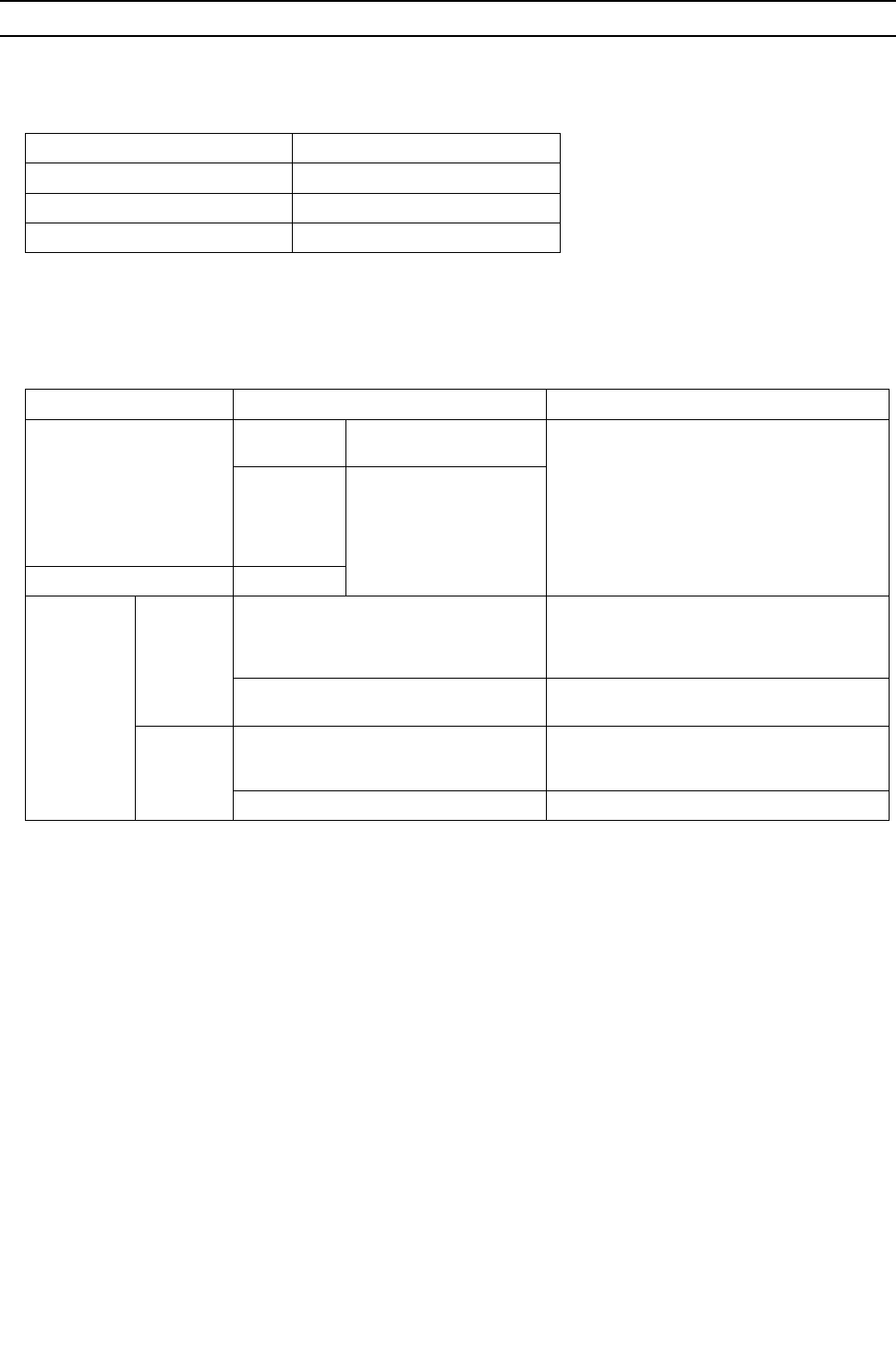
at the same radial thickness.
Maximum working pressure Refrigerant type
3.45 MPa [500psi] R22, R407C etc.
4.30 MPa [624psi] R410A etc.
Pipe size (mm[in]) Radial thickness (mm) Type
ø6.35 [1/4"] 0.8t
O-material (Annealed)
ø9.52 [3/8"] 0.8t
ø12.7 [1/2"] 0.8t
ø15.88 [5/8"] 1.0t
ø19.05 [3/4"] 1.0t
1/2H-material,
H-material (Drawn)
ø22.2 [7/8"] 1.0t
ø25.4 [1"] 1.0t
ø28.58 [1-1/8"] 1.0t
ø31.75 [1-1/4"] 1.1t
ø34.93 [1-3/8"] 1.1t
ø41.28 [1-5/8"] 1.2t
Do not use the existing piping!
[ I Read Before Servicing ]
- 6 -
HWE09080 GB
4. Thickness and refrigerant type indicated on the piping materials
Ask the pipe manufacturer for the symbols indicated on the piping material for new refrigerant.
5. Flare processing (O-material (Annealed) and OL-material only)
The flare processing dimensions for the pipes that are used in the R410A system are larger than those in the R22 system.
(ø19.05 pipes should have a radial thickness of 1.2 t and be made of annealed materials.)
If a clutch-type flare tool is used to flare the pipes in the system using R410A, the length of the pipes must be between 1.0
and 1.5 mm. For margin adjustment, a copper pipe gauge is necessary.
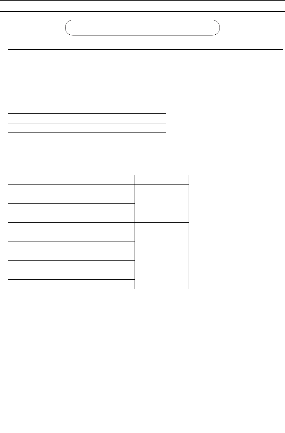
6. Flare nut
The flare nut type has been changed to increase the strength. The size of some of the flare nuts have also been changed.
The figures in the radial thickness column are based on the Japanese standards and provided only as a reference. Use pipes
that meet the local standards.
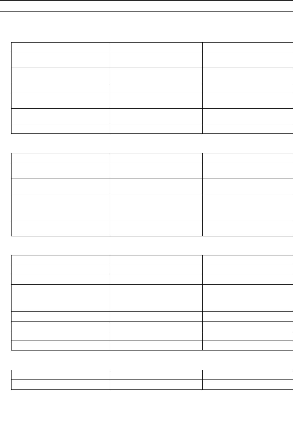
Flare processing dimensions (mm[in])
Pipe size (mm[in]) A dimension (mm)
R410A R22, R407C
ø6.35 [1/4"] 9.1 9.0
ø9.52 [3/8"] 13.2 13.0
ø12.7 [1/2"] 16.6 16.2
ø15.88 [5/8"] 19.7 19.4
ø19.05 [3/4"] 24.0 23.3
Flare nut dimensions (mm[in])
Pipe size (mm[in]) B dimension (mm)
R410A R22, R407C
ø6.35 [1/4"] 17.0 17.0
ø9.52 [3/8"] 22.0 22.0
ø12.7 [1/2"] 26.0 24.0
ø15.88 [5/8"] 29.0 27.0
ø19.05 [3/4"] 36.0 36.0
Dimension A
Dimension B
[ I Read Before Servicing ]
- 7 -
HWE09080 GB
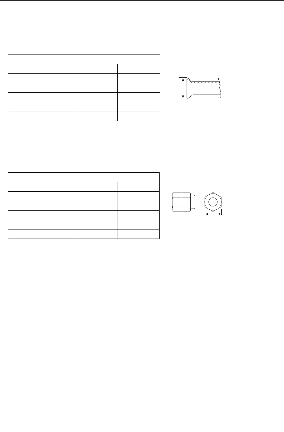
[4] Storage of Piping
1. Storage location
Store the pipes to be used indoors. (Warehouse at site or owner's warehouse)
If they are left outdoors, dust, dirt, or moisture may infiltrate and contaminate the pipe.
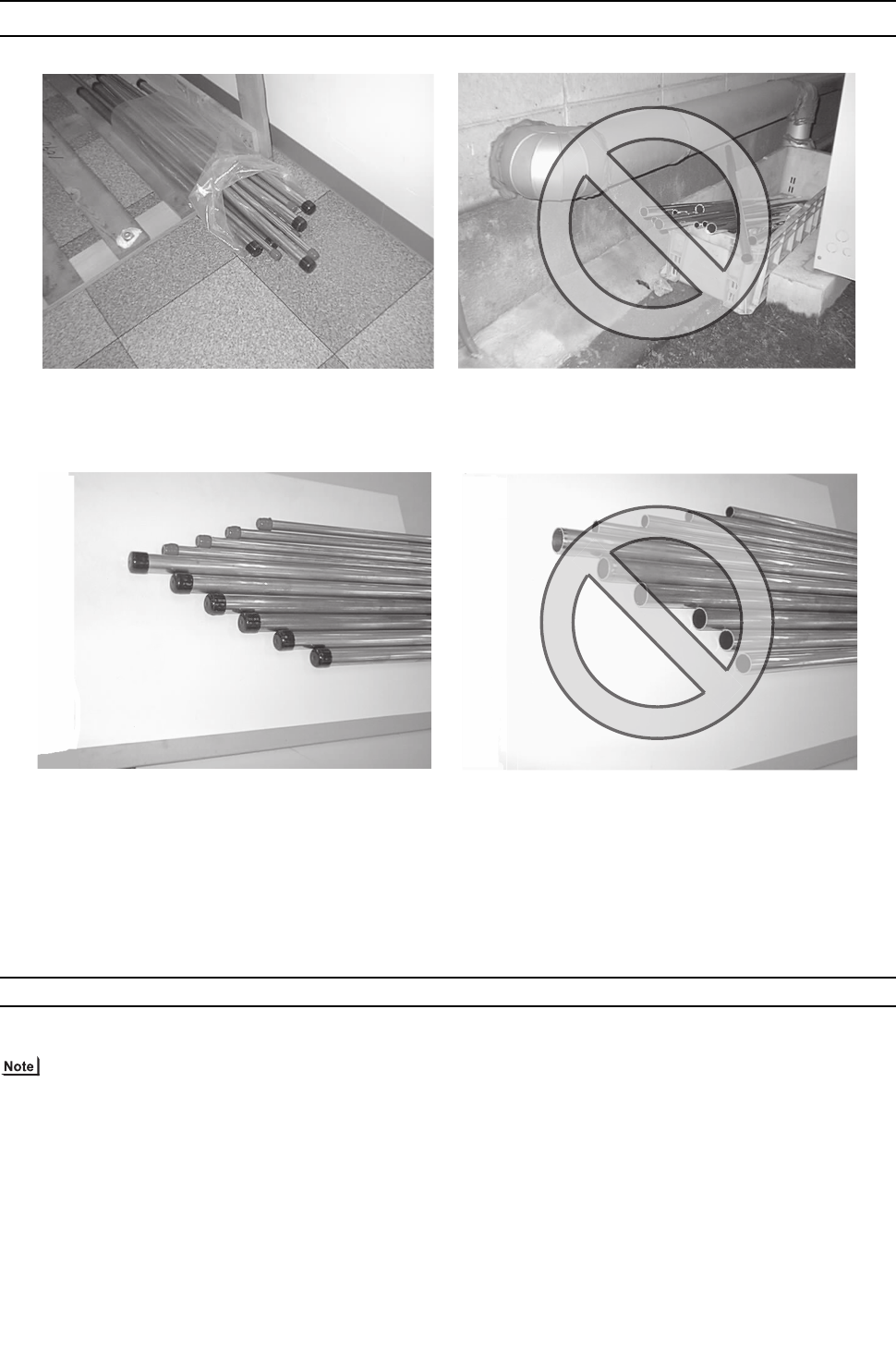
2. Sealing the pipe ends
Both ends of the pipes should be sealed until just before brazing.
Keep elbow pipes and T-joints in plastic bags.
The new refrigerator oil is 10 times as hygroscopic as the conventional refrigerating machine oil (such as Suniso) and, if not
handled with care, could easily introduce moisture into the system. Keep moisture out of the pipes, for it will cause the oil to
deteriorate and cause a compressor failure.
[5] Pipe Processing
Use a small amount of ester oil, ether oil, or alkylbenzene to coat flares and flanges.
Use a minimum amount of oil.
Use only ester oil, ether oil, and alkylbenzene.
[ I Read Before Servicing ]
- 8 -
HWE09080 GB
[6] Brazing
No changes have been made in the brazing procedures. Perform brazing with special care to keep foreign objects (such as oxide
scale, water, and dust) out of the refrigerant system.
Example: Inside the brazed connection
1. Items to be strictly observed
Do not conduct refrigerant piping work outdoors if raining.
Use non-oxidized solder.
Use a brazing material (BCuP-3) that requires no flux when brazing between copper pipes or between a copper pipe and
copper coupling.
If installed refrigerant pipes are not immediately connected to the equipment, then braze and seal both ends.
2. Reasons
The new refrigerating machine oil is 10 times as hygroscopic as the conventional oil and is more likely to cause unit failure if
water infiltrates into the system.
Flux generally contains chloride. Residual flux in the refrigerant circuit will cause sludge to form.
3. Notes
Do not use commercially available antioxidants because they may cause the pipes to corrode or refrigerating machine oil to
deteriorate.
Use of oxidized solder for brazing Use of non-oxidized solder for brazing
[ I Read Before Servicing ]
- 9 -
HWE09080 GB
[7] Air Tightness Test
No changes have been made in the detection method. Note that a refrigerant leak detector for R22 will not detect an R410A leak.
1. Items to be strictly observed
Pressurize the equipment with nitrogen up to the design pressure (4.15MPa[601psi]), and then judge the equipment's air tight-
ness, taking temperature variations into account.
Refrigerant R410A must be charged in its liquid state (vs. gaseous state).
2. Reasons
Oxygen, if used for an air tightness test, poses a risk of explosion. (Only use nitrogen to check air tightness.)
Refrigerant R410A must be charged in its liquid state. If gaseous refrigerant in the cylinder is drawn out first, the composition
of the remaining refrigerant in the cylinder will change and become unsuitable for use.
3. Notes
Procure a leak detector that is specifically designed to detect an HFC leak. A leak detector for R22 will not detect an
HFC(R410A) leak.
Halide torch R22 leakage detector
[ I Read Before Servicing ]
- 10 -
HWE09080 GB
[8] Vacuum Drying (Evacuation)
1. Vacuum pump with a reverse-flow check valve (Photo1)
To prevent the vacuum pump oil from flowing into the refrigerant circuit during power OFF or power failure, use a vacuum
pump with a reverse-flow check valve.
A reverse-flow check valve may also be added to the vacuum pump currently in use.
2. Standard of vacuum degree (Photo 2)
Use a vacuum pump that attains 0.5Torr(65Pa) or lower degree of vacuum after 5 minutes of operation, and connect it directly
to the vacuum gauge. Use a pump well-maintained with an appropriate lubricant. A poorly maintained vacuum pump may not
be able to attain the desired degree of vacuum.
3. Required precision of vacuum gauge
Use a vacuum gauge that registers a vacuum degree of 5Torr(650Pa) and measures at intervals of 1Torr(130Pa). (A recom-
mended vacuum gauge is shown in Photo2.)
Do not use a commonly used gauge manifold because it cannot register a vacuum degree of 5Torr(650Pa).
4. Evacuation time
After the degree of vacuum has reached 5Torr(650Pa), evacuate for an additional 1 hour. (A thorough vacuum drying re-
moves moisture in the pipes.)
Verify that the vacuum degree has not risen by more than 1Torr(130Pa) 1hour after evacuation. A rise by less than
1Torr(130Pa) is acceptable.
If the vacuum is lost by more than 1Torr(130Pa), conduct evacuation, following the instructions in section 6. Special vacuum
drying.
5. Procedures for stopping vacuum pump
To prevent the reverse flow of vacuum pump oil, open the relief valve on the vacuum pump side, or draw in air by loosening
the charge hose, and then stop the operation.
The same procedures should be followed when stopping a vacuum pump with a reverse-flow check valve.
6. Special vacuum drying
When 5Torr(650Pa) or lower degree of vacuum cannot be attained after 3 hours of evacuation, it is likely that water has pen-
etrated the system or that there is a leak.
If water infiltrates the system, break the vacuum with nitrogen. Pressurize the system with nitrogen gas to
0.5kgf/cm2G(0.05MPa) and evacuate again. Repeat this cycle of pressurizing and evacuation either until the degree of vac-
uum below 5Torr(650Pa) is attained or until the pressure stops rising.
Only use nitrogen gas for vacuum breaking. (The use of oxygen may result in an explosion.)
(Photo1) 15010H (Photo2) 14010
Recommended vacuum gauge:
ROBINAIR 14010 Thermistor Vacuum Gauge

[ I Read Before Servicing ]
- 11 -
HWE09080 GB
7. Notes
To evacuate air from the entire system
Applying a vacuum through the check joints at the refrigerant service valve (BV1 and 2) is not enough to attain the
desired vacuum pressure.
Be sure to apply a vacuum through the check joints at the refrigerant service valve (BV1 and 2) and also through the
check joints on the high and low pressure sides (CJ1 and 2).
To evacuate air only from the heat source units
Apply a vacuum through the check joints on the high and low pressure sides (CJ1, and 2).
To evacuate air from the indoor units and extension pipes
Apply a vacuum through the check joints at the refrigerant service valve (BV1 and 2).
[ I Read Before Servicing ]
- 12 -
HWE09080 GB
[9] Refrigerant Charging
1. Reasons
R410A is a pseudo-azeotropic HFC blend (boiling point R32=-52°C[-62°F], R125=-49°C[-52°F]) and can almost be handled
the same way as a single refrigerant, such as R22. To be safe, however, draw out the refrigerant from the cylinder in the liquid
phase. If the refrigerant in the gaseous phase is drawn out, the composition of the remaining refrigerant will change and be-
come unsuitable for use.
2. Notes
When using a cylinder with a siphon, refrigerant is charged in the liquid state without the need for turning it upside down. Check
the type of the cylinder on the label before use.
[10] Remedies to be taken in case of a Refrigerant Leak
If the refrigerant leaks out, it may be replenished. The entire refrigerant does not need to be replaced. (Charge refrigerant in the
liquid state.)
Refer to "IX [5] Refrigerant Leak."(page 343)
Cylinder with a siphon
Cylinder color R410A is pink. Refrigerant charging in the liquid state
Cylin-
der
liquid
Valve Valve
liquid
Cylin-
der
Cylinder without a siphon
[ I Read Before Servicing ]
- 13 -
HWE09080 GB
[11] Characteristics of the Conventional and the New Refrigerants
1. Chemical property
As with R22, the new refrigerant (R410A) is low in toxicity and chemically stable nonflammable refrigerant.
However, because the specific gravity of vapor refrigerant is greater than that of air, leaked refrigerant in a closed room will
accumulate at the bottom of the room and may cause hypoxia.
If exposed to an open flame, refrigerant will generate poisonous gases. Do not perform installation or service work in a con-
fined area.
*1 When CFC11 is used as a reference
*2 When CO2 is used as a reference
2. Refrigerant composition
R410A is a pseudo-azeotropic HFC blend and can almost be handled the same way as a single refrigerant, such as R22. To
be safe, however, draw out the refrigerant from the cylinder in the liquid phase. If the refrigerant in the gaseous phase is drawn
out, the composition of the remaining refrigerant will change and become unsuitable for use.
If the refrigerant leaks out, it may be replenished. The entire refrigerant does not need to be replaced.
3. Pressure characteristics
The pressure in the system using R410A is 1.6 times as great as that in the system using R22.
New Refrigerant (HFC type) Conventional Refriger-
ant (HCFC type)
R410A R407C R22
R32/R125 R32/R125/R134a R22
Composition (wt%) (50/50) (23/25/52) (100)
Type of Refrigerant Pseudo-azeotropic
Refrigerant
Non-azeotropic
Refrigerant
Single Refrigerant
Chloride Not included Not included Included
Safety Class A1/A1 A1/A1 A1
Molecular Weight 72.6 86.2 86.5
Boiling Point (°C/°F) -51.4/-60.5 -43.6/-46.4 -40.8/-41.4
Steam Pressure
(25°C,MPa/77°F,psi) (gauge)
1.557/226 0.9177/133 0.94/136
Saturated Steam Density
(25°C,kg/m3/77°F,psi)
64.0 42.5 44.4
Flammability Nonflammable Nonflammable Nonflammable
Ozone Depletion Coefficient (ODP)*1 0 0 0.055
Global Warming Coefficient (GWP)*2 1730 1530 1700
Refrigerant Charging Method Refrigerant charging in
the liquid state
Refrigerant charging in
the liquid state
Refrigerant charging in
the gaseous state
Replenishment of Refrigerant after a Refrigerant
Leak
Available Available Available
Temperature (°C/°F)
Pressure (gauge)
R410A R407C R22
MPa/psi MPa/psi MPa/psi
-20/-4 0.30/44 0.18/26 0.14/20
0/32 0.70/102 0.47/68 0.40/58
20/68 1.34/194 0.94/136 0.81/117
40/104 2.31/335 1.44/209 1.44/209
60/140 3.73/541 2.44/354 2.33/338
65/149 4.17/605 2.75/399 2.60/377
[ I Read Before Servicing ]
- 14 -
HWE09080 GB
[12] Notes on Refrigerating Machine Oil
1. Refrigerating machine oil in the HFC refrigerant system
HFC type refrigerants use a refrigerating machine oil different from that used in the R22 system.
Note that the ester oil used in the system has properties that are different from commercially available ester oil.
2. Effects of contaminants*1
Refrigerating machine oil used in the HFC system must be handled with special care to keep contaminants out.
The table below shows the effect of contaminants in the refrigerating machine oil on the refrigeration cycle.
3. The effects of contaminants in the refrigerating machine oil on the refrigeration cycle.
Refrigerant Refrigerating machine oil
R22 Mineral oil
R407C Ester oil
R410A Ester oil
*1. Contaminants is defined as moisture, air, processing oil, dust/dirt, wrong types of refrigerant, and refrigerating machine oil.
Cause Symptoms Effects on the refrigerant cycle
Water infiltration Frozen expansion valve
and capillary tubes
Clogged expansion valve and capillary tubes
Poor cooling performance
Compressor overheat
Motor insulation failure
Burnt motor
Coppering of the orbiting scroll
Lock
Burn-in on the orbiting scroll
Hydrolysis
Sludge formation and ad-
hesion
Acid generation
Oxidization
Oil degradation
Air infiltration Oxidization
Infiltration of
contaminants
Dust, dirt
Adhesion to expansion valve and capillary
tubes
Clogged expansion valve, capillary tubes, and
drier
Poor cooling performance
Compressor overheat
Infiltration of contaminants into the com-
pressor
Burn-in on the orbiting scroll
Mineral oil
etc.
Sludge formation and adhesion Clogged expansion valve and capillary tubes
Poor cooling performance
Compressor overheat
Oil degradation Burn-in on the orbiting scroll

- 15 -
HWE09080 GB
II
Restrictions
[1] System configuration ....................................................................................................... 17
[2] Types and Maximum allowable Length of Cables ........................................................... 18
[3] Switch Settings and Address Settings ............................................................................. 19
[4] Sample System Connection............................................................................................. 26
[5] An Example of a System to which an MA Remote Controller is connected..................... 27
[6] An Example of a System to which an ME Remote Controller is connected..................... 49
[7] An Example of a System to which both MA Remote Controller and
ME Remote Controller are connected.............................................................................. 53
[8] Restrictions on Pipe Length .............................................................................................58

- 16 -
[ II Restrictions ]
- 17 -
HWE09080 GB
II Restrictions
[1] System configuration
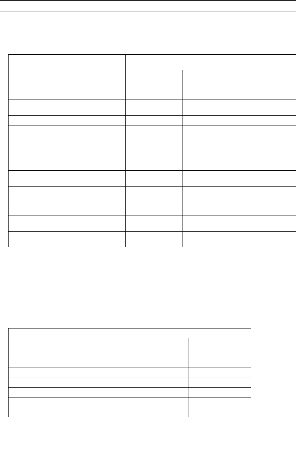
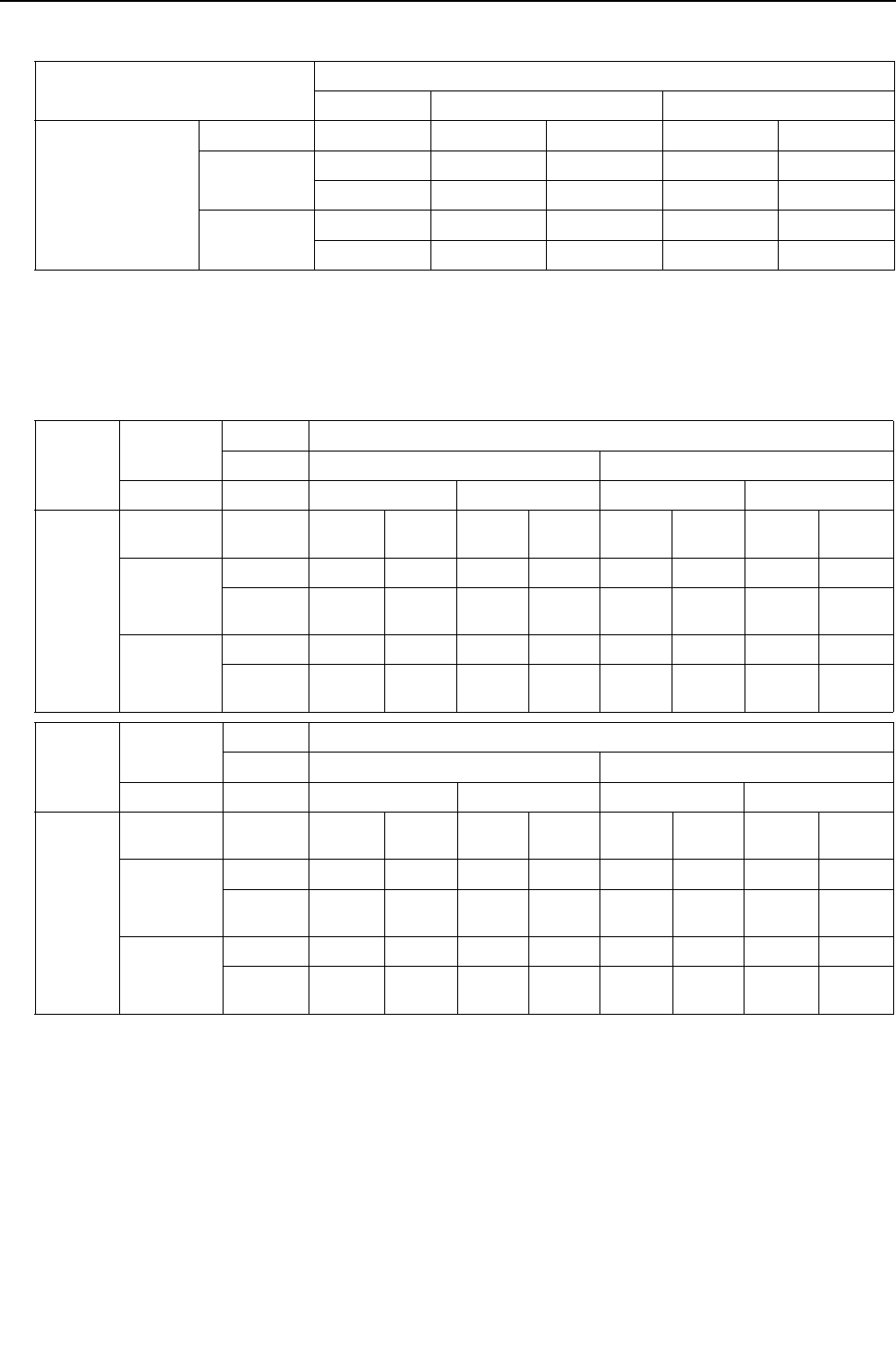
1. Table of compatible indoor units <PQHY>
The table below summarizes the types of indoor units that are compatible with different types of heat source units.
1) "Maximum total capacity of connectable indoor units" refers to the sum of the numeric values in the indoor unit model names.
2) If the total capacity of the indoor units that are connected to a given heat source unit exceeds the capacity of the heat source
unit, the indoor units will not be able to perform at the rated capacity when they are operated simultaneously. Select a com-
bination of units so that the total capacity of the connected indoor units is at or below the capacity of the heat source unit
whenever possible.
1. Table of compatible indoor units <PQRY>
The table below summarizes the types of indoor units that are compatible with different types of heat source units.
1) "Maximum total capacity of connectable indoor units" refers to the sum of the numeric values in the indoor unit model names.
2) If the total capacity of the indoor units that are connected to a given heat source unit exceeds the capacity of the heat source
unit, the indoor units will not be able to perform at the rated capacity when they are operated simultaneously. Select a com-
bination of units so that the total capacity of the connected indoor units is at or below the capacity of the heat source unit
whenever possible.
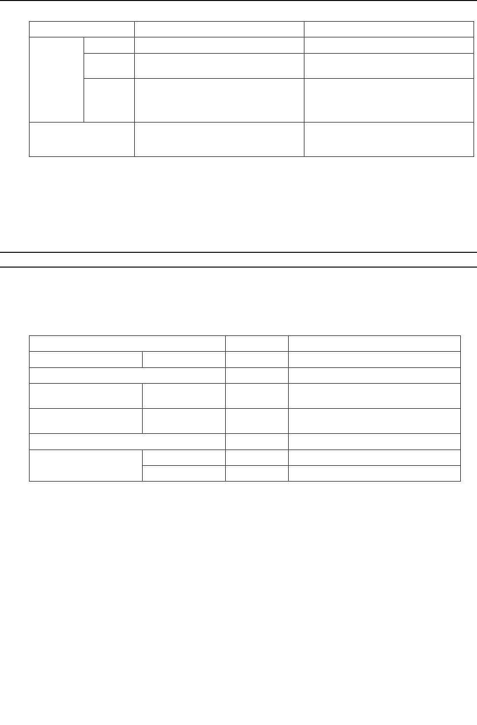
Heat
source
units
Composing units Maximum total capacity
of connectable indoor
units
Maximum number
of connectable in-
door units
Types of connectable in-
door units
P72 - - - 36 - 93 1 - 15 P06 - P96 models
R410A series indoor units
P96 - - - 48 - 124 1 - 20
P120 - - - 60 - 156 1 - 26
P144 P72 P72 - 72 - 187 1 - 31
P168 P96 P72 - 84 - 218 1 - 36
P192 P96 P96 - 96 - 249 1 - 41
P216 P120 P96 - 108 - 280 2 - 46
P240 P120 P120 - 120 - 312
2 - 50
P264 P96 P96 P72 132 - 343
P288 P96 P96 P96 144 - 374
P312 P120 P96 P96 156- 405
P336 P120 P120 P96 168 - 436
P360 P120 P120 P120 180 - 468
Heat
source
units
Composing units Maximum total capacity
of connectable indoor
units
Maximum number
of connectable in-
door units
Types of connectable in-
door units
P72 - - 36- 108 1 - 18 P06 - P96 models
R410A series indoor units
P96 - - 48 - 144 1 - 24
P120 - - 60 - 180 1 - 30
P144 P72 P72 72 - 216 1 - 36
P168 P96 P72 84 - 252 1 - 42
P192 P96 P96 96 - 288 1 - 48
P216 P120 P96 108 - 324 2 - 50
P240 P120 P120 120 - 360
[ II Restrictions ]
- 18 -
HWE09080 GB
[2] Types and Maximum allowable Length of Cables
1. Wiring work
(1) Notes
1) Have all electrical work performed by an authorized electrician according to the local regulations and instructions in this man-
ual.
2) Install external transmission cables at least 5cm [1-31/32"] away from the power supply cable to avoid noise interference.
(Do not put the control cable and power supply cable in the same conduit tube.)
3) Provide grounding for the heat source unit as required.
4) Run the cable from the electric box of the indoor or heat source unit in such way that the box is accessible for servicing.
5) Do not connect power supply wiring to the terminal block for transmission line. Doing so will damage the electronic compo-
nents on the terminal block.
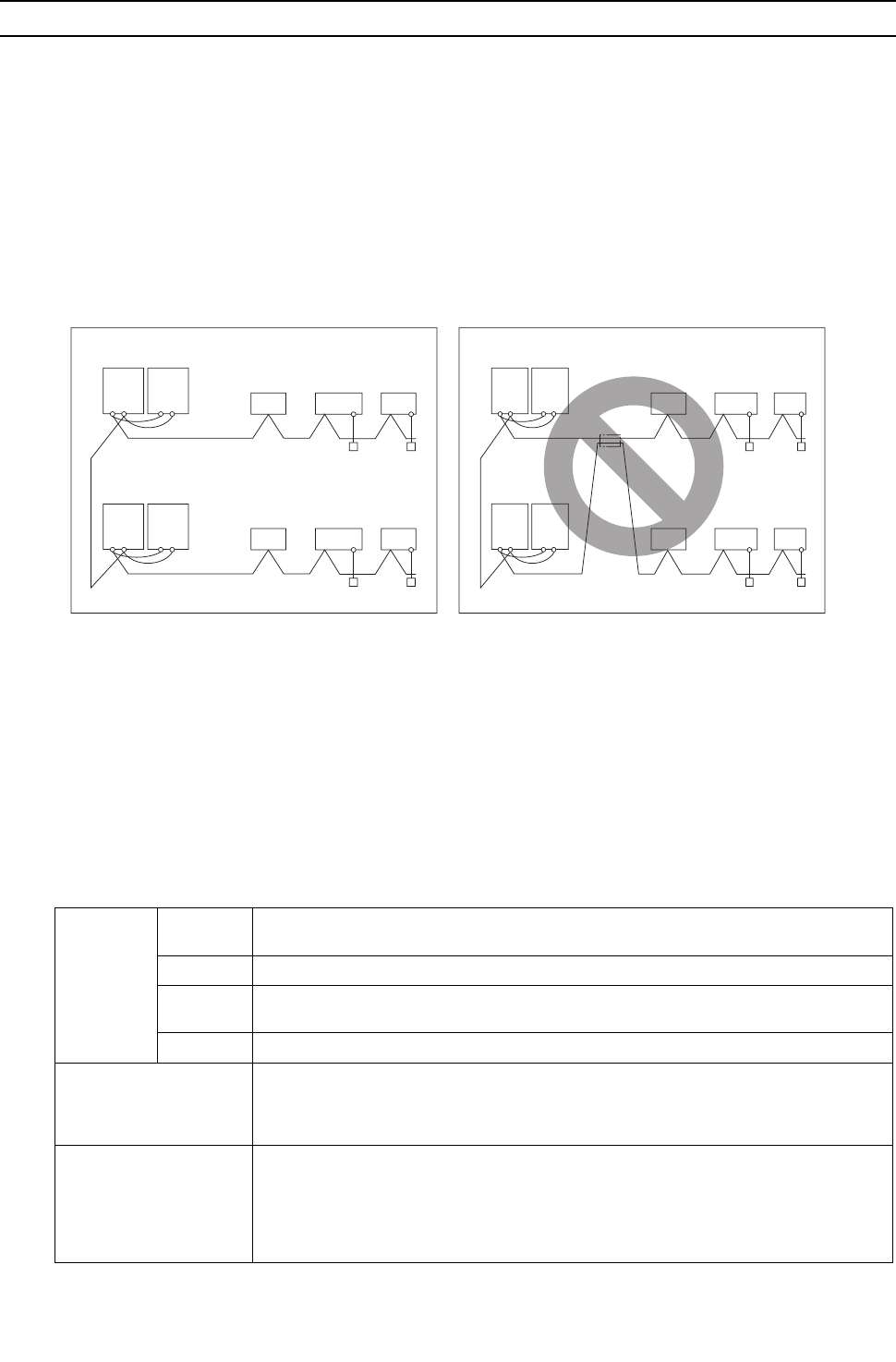
6) Use 2-core shielded cables as transmission cables.
Use a separate 2-core control cable for each refrigerant system. Do not use a single multiple-core cable to connect indoor
units that belong to different refrigerant systems. The use of a multiple-core cable may result in signal transmission errors and
malfunctions.
(2) Control wiring
Different types of control wiring are used for different systems.
Refer to section "[5] An Example of a System to which an MA Remote Controller is connected - [7] An Example of a System
to which both MA Remote Controller and ME Remote Controller are connected" before performing wiring work.
Types and maximum allowable length of cables
Control lines are categorized into 2 types: transmission line and remote controller line.
Use the appropriate type of cables and observe the maximum allowable length specified for a given system. If a given system
has a long transmission line or if a noise source is located near the unit, place the unit away from the noise source to reduce
noise interference.
1) M-NET transmission line
Cable type
Facility
type All facility types
Type Shielded cable CVVS, CPEVS, MVVS
Number of
cores 2-core cable
Cable size Larger than 1.25mm2 [AWG16]
Maximum transmission
line distance between the
heat source unit and the
farthest indoor unit
200 m [656ft] max.
Maximum transmission
line distance for central-
ized control and Indoor-
heat source transmission
line (Maximum line dis-
tance via heat source unit)
500 m [1640ft] max.
*The maximum overall line length from the power supply unit on the transmission lines for
centralized control to each heat source unit or to the system controller is 200m [656ft] max.
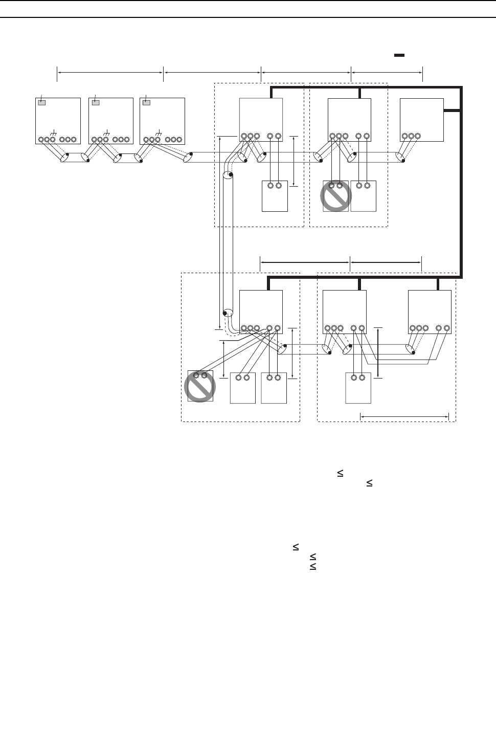
TB
3TB
7TB
3TB
7
TB
3TB
7TB
3TB
7
TB
3TB
7TB
3TB
7
TB
3TB
7TB
3TB
7
TB3: Terminal block for indoor-heat source transmission line TB7: Terminal block for centralized control
multiple-core cable
BC Controller Indoor unit
Remote Controller
Remote Controller
2-core shielded cable
2-core shielded cable
Heat source unit
BC Controller Indoor unit
Heat source unit
[ II Restrictions ]
- 19 -
HWE09080 GB
2) Remote controller wiring
*1 MA remote controller refers to MA remote controller (PAR-20MAA, PAR-21MAA), MA simple remote controller, and
wireless remote controller.
*2 M-NET remote controller refers to ME remote controller and ME simple remote controller.
*3 The use of cables that are smaller than 0.75mm2 [AWG18] is recommended for easy handling.
*4 When connected to the terminal block on the Simple remote controller, use cables that meet the cable size specifi-
cations shown in the parenthesis.
[3] Switch Settings and Address Settings
1. Switch setting
Refer to section "[5] An Example of a System to which an MA Remote Controller is connected - [7] An Example of a System
to which both MA Remote Controller and ME Remote Controller are connected" before performing wiring work.
Set the switches while the power is turned off.
If the switch settings are changed while the unit is being powered, those changes will not take effect, and the unit will not
function properly.
*1. Applicable when LOSSNAY units are connected to the indoor-heat source transmission line.
*2. The heat source units in the same refrigerant circuit are automatically designated as OC and OS in the order of capacity
from large to small (if two or more units have the same capacity, in the order of address from small to large).
*3. Turn off the power to all the heat source units in the same refrigerant circuit.
MA remote controller*1 M-NET remote controller*2
Cable type
Type VCTF, VCTFK, CVV, CVS, VVR, VVF, VCT Shielded cable MVVS
Number of
cores 2-core cable 2-core cable
Cable size
0.3 to 1.25mm2 *3
[AWG22 to 16]
(0.75 to 1.25mm2 ) *4
[AWG18 to 16]
0.3 to 1.25mm2 *3
[AWG22 to 16]
(0.75 to 1.25mm2 ) *4
[AWG18 to 16]
Maximum overall line
length 200 m [656ft] max.
The section of the cable that exceeds 10m
[32ft] must be included in the maximum in-
door-heat source transmission line distance.
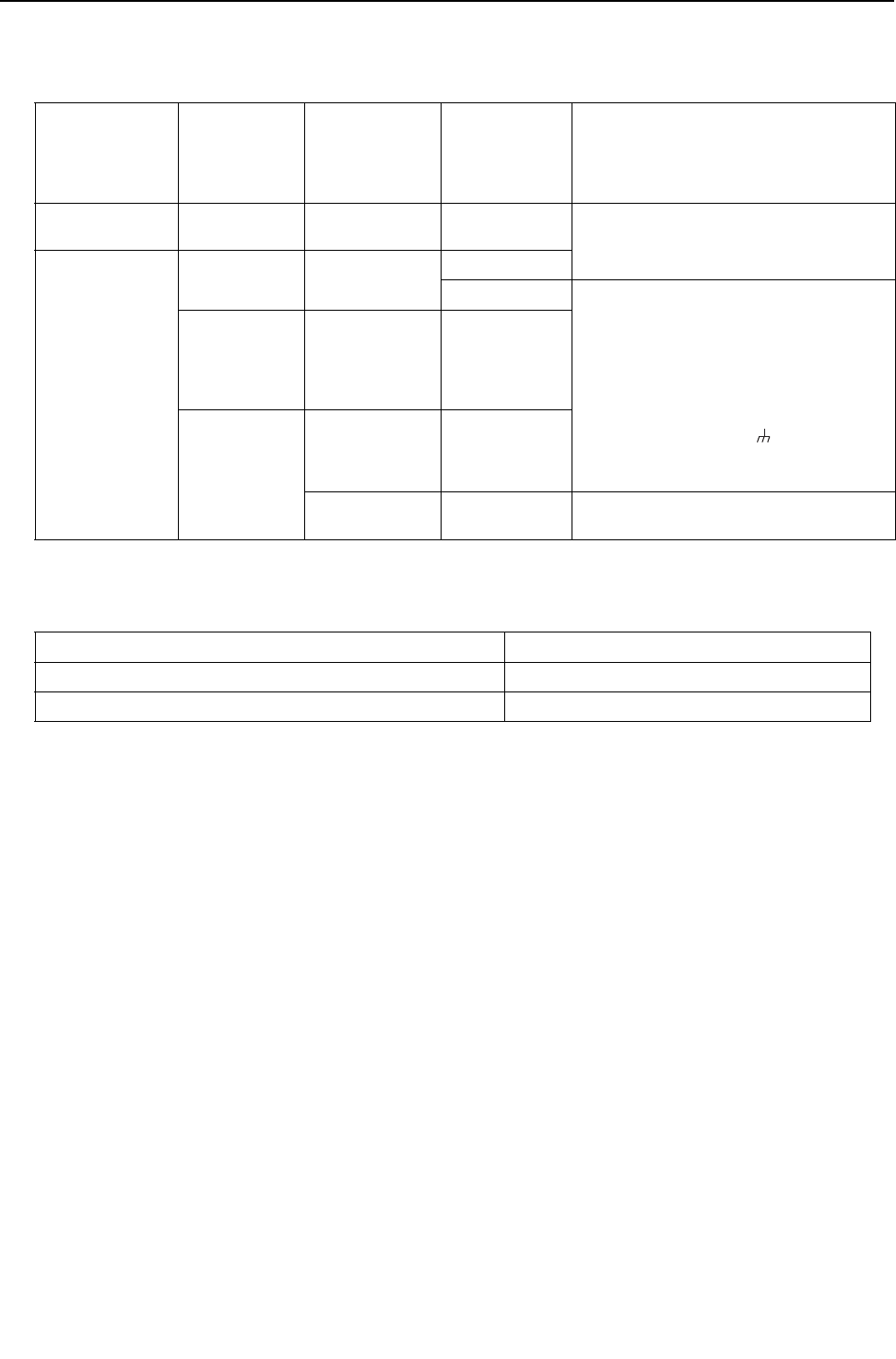
Units on which to set the switches Symbol Units to which the power must be shut off
CITY MULTI indoor unit Main/sub unit IC Heat source units *3 and Indoor units
LOSSNAY, OA processing unit *1 LC Heat source units *3 and LOSSNAY
M-NET remote controller Main/sub remote
controller
RC Heat source units *3
MA remote controller Main/sub remote
controller
MA Indoor units
CITY MULTI heat source unit*2 OC,OS Heat source units *3
BC controller Main BC Heat source units *3 and BC controller
Sub1, 2 BS1, BS2 Heat source units *3 and BC controller

[ II Restrictions ]
- 20 -
HWE09080 GB
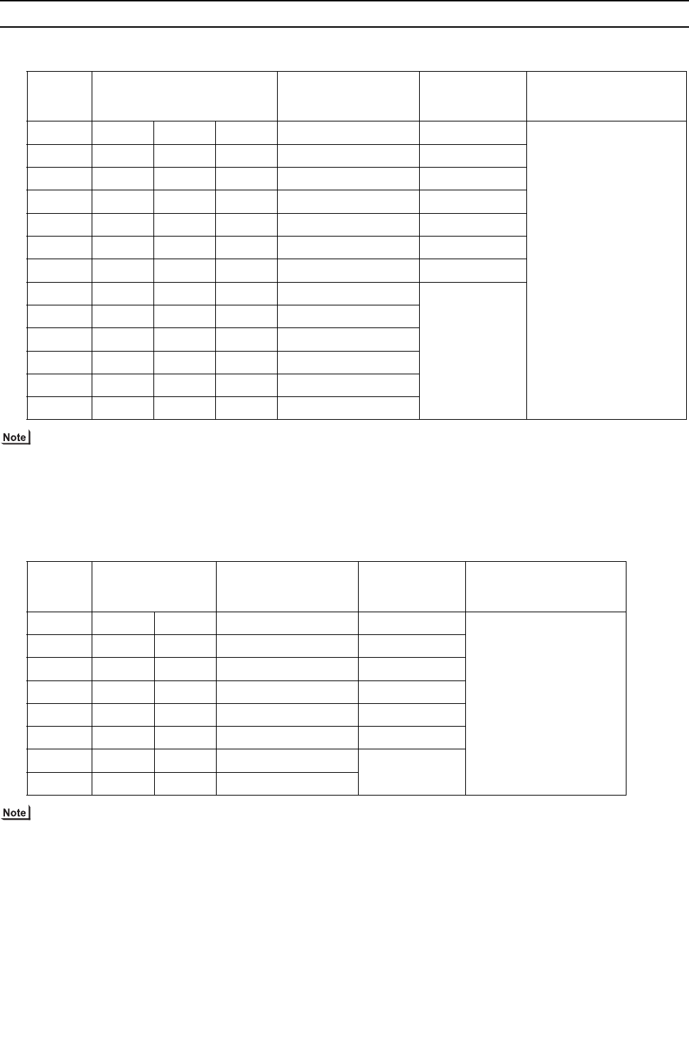
2. M-NET Address settings
(1) Address settings table
The need for address settings and the range of address setting depend on the configuration of the system.
*1. If a given address overlaps any of the addresses that are assigned to other units, use a different, unused address within the
setting range.
*2. To set the heat source unit address or the auxiliary heat source unit address to "100," set the rotary switches to "50."
*3. To set the M-NET remote controller address to "200," set the rotary switches to "00."
*4. Some models of indoor units have two or three control boards.
Assign an address to the No.1, No. 2, and No. 3 control boards so that the No. 2 control board address equals the No. 1 control
board address plus 1, and that the No. 3 control board address equals the No. 1 control board address plus 2.
*5. The heat source units in the same refrigerant circuit are automatically designated as OC, and OS. They are designated as
OC, and OS in the descending order of capacity (ascending order of address if the capacities are the same).
*6. No address settings are required for units in a system with a single heat source unit (with some exceptions).
Address setting is required if a sub BC controller is connected.
Unit or controller Sym-
bol
Address
setting
range
Setting method Factory
address
setting
CITY MULTI
indoor unit
Main/sub unit IC 0, 01 to
50*1 *4 *6 Assign the smallest address to the main indoor unit in the
group, and assign sequential address numbers to the rest
of the indoor units in the same group.
In an R2 system with a sub BC controller, make the set-
tings for the indoor units in the following order.
(i) Indoor unit to be connected to the main BC controller
(ii) Indoor unit to be connected to sub BC controller 1
(iii) Indoor unit to be connected to sub BC controller 2
Make the settings for the indoor units in the way that the
formula "(i) < (ii) < (iii)" is true.
00
M-NET
adapter
M-NET con-
trol interface
Free Plan
adapter
LOSSNAY, OA processing unit LC 0, 01 to
50*1 *4 *6 Assign an arbitrary but unique address to each of these
units after assigning an address to all indoor units.
00
M-NET re-
mote con-
troller
Main remote
controller
RC 101 to
150
Add 100 to the smallest address of all the indoor units in
the same group.
101
Sub remote
controller
RC 151 to
200*3 Add 150 to the smallest address of all the indoor units in
the same group.
MA remote controller MA No address settings required. (The main/sub setting must be made if
2 remote controllers are connected to the system.)
Main
CITY MULTI heat source unit OC
OS
0, 51 to
100*1 *2
*6
Assign an address that equals the lowest address of the in-
door units in the same refrigerant circuit plus 50.
Assign sequential addresses to the heat source units in the
same refrigerant circuit. The heat source units in the same
refrigerant circuit are automatically designated as OC and
OS. *5
00
Auxiliary
heat source
unit
BC controller
(main)
BC 0, 51 to
100*1 *2
*6
Assign an address that equals the address of the heat
source unit in the same refrigerant system plus 1.
If a given address overlaps any of the addresses that are
assigned to the heat source units or to the sub BC con-
troller, use a different, unused address within the setting
range.
00
BC controller
(sub1, 2)
BS1
BS2
51 to
100 *2
Assign an address to both the sub BC controller 1 and 2
that equals the lowest address of the indoor units that
are connected to each of them plus 50.
If a sub BC controller is connected, the automatic startup
function is not available.
System
controller
Group remote con-
troller
GR
SC
201 to
250
Assign an address that equals the sum of the smallest
group number of the group to be controlled and 200.
201
System remote con-
troller
SR
SC
Assign an arbitrary but unique address within the range
listed on the left to each unit.
ON/OFF remote con-
troller
AN
SC
Assign an address that equals the sum of the smallest
group number of the group to be controlled and 200.
Schedule timer (com-
patible with M-NET)
ST
SC
Assign an arbitrary but unique address within the range
listed on the left to each unit.
202
Central controller
AG-150A, G(B)-50A
TR
SC
0, 201 to
250
Assign an arbitrary but unique address within the range
listed on the left to each unit. The address must be set to
"0" to control the K-control unit.
000
Expansion controller
PAC-YG50ECA
LM adapter SC 201 to
250
Assign an arbitrary but unique address within the range
listed on the left to each unit.
247
[ II Restrictions ]
- 21 -
HWE09080 GB
(2) Power supply switch connector connection on the heat source unit
(Factory setting: The male power supply switch connector is connected to CN41.)
There are limitations on the total number of units that are connectable to each refrigerant system. Refer to the DATABOOK
for details.
*1 The need for a power supply unit for transmission lines depends on the system configuration.
*2 The replacement of the power jumper connector from CN41 to CN40 must be performed on only one heat source unit in
the system.
(3) Settings for the centralized control switch for the heat source unit (Factory setting: SW2-1 are set to OFF.)
(4) Selecting the position of temperature detection for the indoor unit (Factory setting: SW1-1 set to "OFF".)
To stop the fan during heating Thermo-OFF (SW1-7 and 1-8 on the indoor units to be set to ON), use the built-in thermistor
on the remote controller or an optional thermistor.
1) To use the built-in sensor on the remote controller, set the SW1-1 to ON.
Some models of remote controllers are not equipped with a built-in temperature sensor.
Use the built-in temperature sensor on the indoor unit instead.
When using the built-in sensor on the remote controller, install the remote controller where room temperature can be detected.
(Note) Factory setting for SW1-1 on the indoor unit of the All-Fresh Models is ON.
2) When an optional temperature sensor is used, set SW1-1 to OFF, and set SW3-8 to ON.
When using an optional temperature sensor, install it where room temperature can be detected.
System configura-
tion
Connection to
the system con-
troller
Power supply unit
for transmission
lines
Group operation
of units in a sys-
tem with multiple
heat source
units
Power supply switch connector connection
System with one
heat source unit
_ _ _ Leave CN41 as it is
(Factory setting)
System with multi-
ple heat source
units
Not connected _ Not grouped
Grouped Disconnect the male connector from the fe-
male power supply switch connector (CN41)
and connect it to the female power supply
switch connector (CN40) on only one of the
heat source units.*2
*Connect the S (shielded) terminal on the
terminal block (TB7) on the heat source
unit whose CN41 was replaced with CN40
to the ground terminal ( ) on the electric
box.
With connection
to the indoor-
heat source
transmission
line
Not required Grouped/not
grouped
With connection
to the central-
ized control sys-
tem
Not required*1
(Powered from
the heat source
unit)
Grouped/not
grouped
Required *1 Grouped/not
grouped
Leave CN41 as it is
(Factory setting)
System configuration Centralized control switch settings *1
*1. Set SW2-1 on all heat source units in the same refrigerant circuit to the same setting.
Connection to the system controller Not connected Leave it to OFF. (Factory setting)
Connection to the system controller Connected*2
*2. When only the LM adapter is connected, leave SW2-1 to OFF (as it is).
ON

[ II Restrictions ]
- 22 -
HWE09080 GB
(5) Various start-stop controls (Indoor unit settings)
Each indoor unit (or group of indoor units) can be controlled individually by setting SW 1-9 and 1-10.
*1. Do not cut off power to the heat source unit. Cutting off the power supply to the heat source unit will cut off the power
supply to the crankcase heater and may cause the compressor to malfunction when the unit is put back into operation.
*2. Not applicable to units with a built-in drain pump or humidifier.
*3. Models with a built-in drain pump cannot be turned on/off by the plug individually. All the units in the same refrigerant cir-
cuits will be turned on or off by the plug.
*4. Requires that the dipswitch settings for all the units in the group be made.
*5. Set SW1-9 and SW1-10 to ON to control the external input from/output to the air conditioning units via AG-150A or G(B)-
50A using the PLC software for general equipment. With these settings made, the power start-stop function becomes dis-
abled. To use the auto recovery function after power failure while these settings are made, set SW1-5 to ON.
(6) Miscellaneous settings
Cooling-only setting for the indoor unit: Cooling only model (Factory setting: SW3-1 "OFF.")
When using indoor unit as a cooling-only unit, set SW3-1 to ON.
(7) Various types of control using input-output signal connector on the heat source unit (various connection options)
Function Operation of the indoor unit when the operation is resumed after the unit
was stopped
Setting (SW1)*4 *5
910
Power ON/OFF by the
plug*1,*2,*3 Indoor unit will go into operation regardless of its operation status before
power off (power failure). (In approx. 5 minutes)
OFF ON
Automatic restoration
after power failure
Indoor unit will go into operation if it was in operation when the power was
turned off (or cut off due to power failure). (In approx. 5 minutes)
ON OFF
Indoor unit will remain stopped regardless of its operation status before
power off (power failure).
OFF ON
Type Usage Function Terminal to be
used*1
*1. For detailed drawing, refer to "Example of wiring connection".
Option
Input Prohibiting cooling/heating operation (thermo OFF) by an ex-
ternal input to the heat source unit.
* Usable for demand control of each refrigerant system
DEMAND (level) CN3D*2
*2. For details, refer to the next section "Demand control".
Adapter
for exter-
nal input
(PAC-
SC36NA-
E)
Performs a low level noise operation of the heat source unit by
an external input to the heat source unit.
* It can be used as the silent operation device for each refriger-
ant system.
Low-noise mode
(level)*3 *4
Cooling/heating operation can be changed by an external input
to the heat source unit (OC).
Auto-changeover CN3N
Receives interlock operation signal input from the water circuit
pump (field-supplied)
Pump interlock
operation signal
input
TB-8 (between
poles 3 and 4)
*Minimum guar-
anteed current at
no-voltage input
contact: 5 mA or
below
_
Out-
put
Outputs signals to perform interlocked operation of heat source
unit and water circuit pump
Signal output patterns
*When DIP SW2-7 is set to off (factory setting)
Signals are output while the compressor is in operation.
*When DIP SW2-7 is set to ON
Signals are output from the controller while receiving cool-
ing or heating signal.
Signals are output while the compressor is stopped during
Thermo-OFF.
Pump interlock
operation signal
TB-8 (between
poles 1 and 2)
*Contact rating:
200VAC 1A or
below
_
How to extract signals from the heat source unit
*It can be used as an operation status display device.
*It can be used for an interlock operation with external devic-
es.
Operation status
of the compressor
CN51 Adapter
for exter-
nal output
(PAC-
SC37SA-
E)
Error status
[ II Restrictions ]
- 23 -
HWE09080 GB
*4. By setting Dip SW5-5, the Low-noise mode can be switched between the Capacity priority mode and the Low-noise pri-
ority mode.
When SW5-5 is set to ON: The low-noise mode always remains effective.
When SW5-5 is set to OFF: The low noise mode is cancelled when certain operation pressure criteria are met, and the
unit goes into normal operation (capacity priority mode).
*5. When multiple heat source units exist in one refrigerant circuit system, settings on every heat source unit (signal input)
are required.
CAUTION
1) Wiring should be covered by insulation tube with supplementary insulation.
2) Use relays or switches with IEC or equivalent standard.
3) The electric strength between accessible parts and control circuit should have 2750V or more.
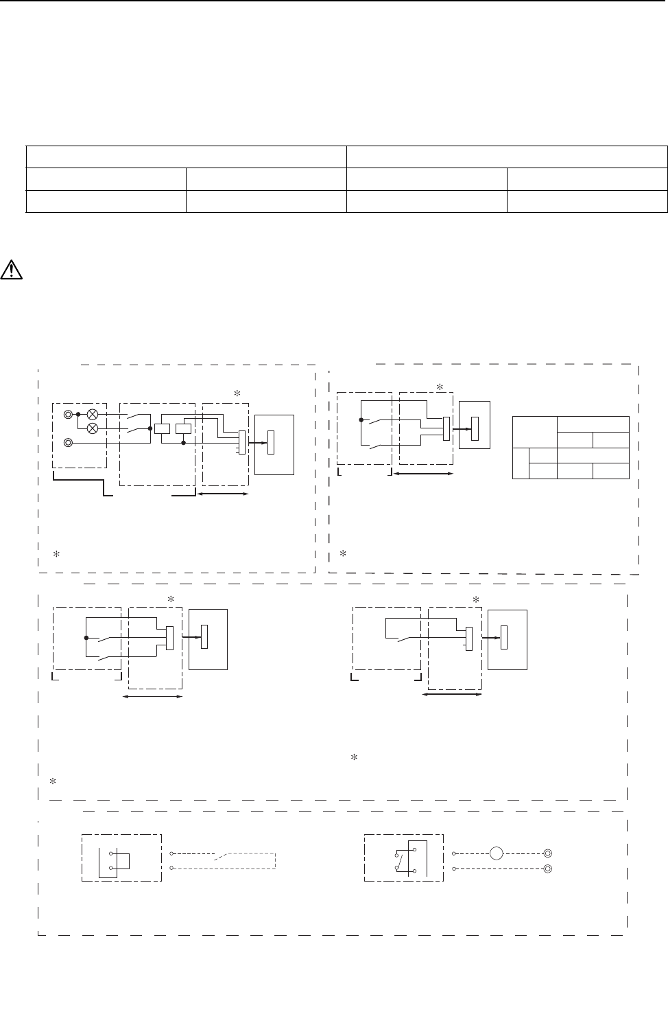
Example of wiring connection
*3. Low-noise mode is valid when Dip SW4-4 on the heat source unit is set to OFF. When DIP SW4-4 is set to ON, 4 levels
of on-DEMAND are possible, using different configurations of low-noise mode input and DEMAND input settings.When
2 or more heat source units exist in one refrigerant circuit system, 8 levels of on-DEMAND are possible. When 3 heat
source units exist in one refrigerant circuitsystem, 12 levels of on-DEMAND are possible.
Low-noise mod is effective. Capacity priority mode becomes effective.
Cooling Heating Cooling Heating
63HS1<32kg/cm263LS>4.6kg/cm263HS1>35kg/cm263LS<3.9kg/cm2
(1) CN51
CN51
X
Y
L
1
L
2
ecruos rewop pmaL
Distant control
board Relay circuit Adapter 1
Heat source unit
control board
Preparations
in the field Maximum cable
length is 10m
5
4
3
XY
L1 : Heat source unit error display lamp
L2 : Compressor operation lamp (compressor running state)
X, Y : Relay (coil =<0.9W : DC12V)
1. Optional part : PAC-SC37SA-E or field supply.
(2) CN3N
2. Optional part : PAC-SC36NA-E or field supply.
Preparations
in the field
OFF
Cooling
ON
Heating
Normal
Y
OFF
ON
X
Contact rating voltage >= DC15V
Contact rating current >= 0.1A
Minimum applicable load =< 1mA at DC
X : Cooling / Heating
Y : Validity / Invalidity of X
X,Y : Relay
CN3N
X
Y
Relay circuit
Adapter
2Heat source unit
control board
Maximum cable
length is 10m
1
2
3
(3) CN3D
2. Optional part : PAC-SC36NA-E or field supply.
X : Low-noise mode
X : Low-noise mode
Y : Compressor ON/OFF
X,Y : Relay Contact rating voltage >= DC15V
Contact rating current >= 0.1A
Minimum appicable load =< 1mA at DC
Y
X
CN3D
TB8 TB8
3X
63PW
4
1
2
Preparations
in the field
Maximum cable
length is 10m
Adapter 2
Heat source unit
control board
3
2
1
Relay circuit
Heat source unit
Pump interlock circuit (if one is connected)
63PW: Pressure switch (Contact: Minimum applied load 5 mA)
X: Relay (Contact rating: 200VAC 1A)
52P: Pump contactor
When connecting the pump interlock circuit wires to terminals
3 and 4 of TB8, remove the short-circuit wire.
Heat source unit
Short-
circuit
wire
2. Optional part : PAC-SC36NA-E or field supply.
X
CN3D
Preparations
in the field
Maximum cable
length is 10m
Adapter 2
Heat source unit
control board
2
3
1
X : Relay
fan frequency and maximum compressor frequency.
Contact rating voltage >= DC15V
Contact rating current >= 0.1A
Minimum applicable load =< 1mA at DC
Low-noise mode : The noise level is reduced by controlling the maximum
Relay circuit
(4)TB8
52P
[ II Restrictions ]
- 24 -
HWE09080 GB
(8) Demand control
1) General outline of control
Demand control is performed by using the external signal input to the 1-2 and 1-3 pins of CN3D on the heat source units (OC,
OS1, and OS2).
Between 2 and 12 steps of demand control is possible by setting DIP SW4-4 on the heat source units (OC, OS1, and OS2).
P200-P300YHM models (single-heat source-unit system): 2 and 4 steps shown in the rows (a) and (b) in the table above
only.
P400-P600YHM models (two-heat source-unit system OC+OS1): 2-8 steps shown in the rows (a), (b), (c), and (e) in the
table above only.
P650-P900YHM models (three-heat source-unit system OC+OS1+OS2): 2-12 steps shown in the rows (a)-(h) in the table
above.
*2. External signal is input to CN3D on the heat source unit whose SW4-4 is set to ON. When SW4-4 is set to OFF on all heat
source units, the signal is input to the CN3D on the OC.
Heat source units whose SW4-4 is set to ON are selectable in a single refrigerant system.
*3. If wrong sequence of steps are taken, the units may go into the Thermo-OFF (compressor stop) mode.
Ex) When switching from 100% to 50%
(Incorrect) 100% to 0% to 50% : The units may go into the Thermo-OFF mode.
(Correct) 100% to 75% to 50%
*4. The percentage of the demand listed in the table above is an approximate value based on the compressor volume and
does not necessarily correspond with the actual capacity.
*5. Notes on using demand control in combination with the low-noise mode
To enable the low-noise mode, it is necessary to short-circuit 1-2 pin of CN3D on the heat source unit whose SW4-4 is set
to OFF.
When SW4-4 is set to ON on all heat source units, the following operations cannot be performed.
Performing 4-step demand in combination with the low-noise operation in a single-heat source-unit system.
Performing 8-step demand in combination with the low-noise operation in a two-heat source-unit system.
Performing 12-step demand in combination with the low-noise operation in a three-heat source-unit system.
2) Contact input and control content
2-step demand control
The same control as the Thermo-OFF is performed by closing 1-3 pin of CN3D.
4-step demand control (When SW4-4 is set to ON on an heat source unit)
Demand capacity is shown below.
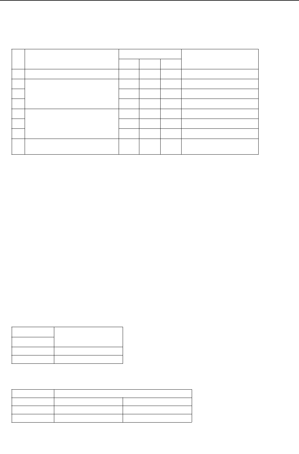
Table.1
No Demand control switch DipSW4-4 Input to CN3D *2
OC OS1 OS2
(a) 2 steps(0-100%) OFF OFF OFF OC
(b) 4 steps(0-50-75-100%) ON OFF OFF OC
(c) OFF ON OFF OS1
(d) OFF OFF ON OS2
(e) 8 steps(0-25-38-50-63-75-88-100%) ON ON OFF OC and OS1
(f) ON OFF ON OC and OS2
(g) OFF ON ON OS1 and OS2
(h) 12 steps(0-17-25-34-42-50-59-67-75-
84-92-100%)
ON ON ON OC, OS1, and OS2
CN3D
1-3P
Open x = 100%
Close x = 0%
CN3D 1-2P
1-3P Open Close
Open 100% 75%
Close 0% 50%
[ II Restrictions ]
- 25 -
HWE09080 GB
8-step demand control (When SW4-4 is set to ON on two heat source units)
Demand capacity is shown below.
*1. The heat source units whose SW4-4 is set to ON are designated as No. 1and No. 2 in the order of address from small to
large.
Ex) When heat source units whose SW4-4 is set to ON are designated as OS1 and OS2, OS1=No. 1 and OS2=No. 2.
12-step demand control (When SW4-4 is set to ON on three heat source units)
Demand capacity is shown below.
*1. The heat source units whose SW4-4 is set to ON are designated as No. 1, No. 2, and No. 3 in the order of address from
small to large.
Ex) When heat source units whose SW4-4 is set to ON are designated as OC, OS1, and OS2, OC=No. 1, OS1=No. 2,
and OS2=No. 3.
8-step demand No.2 CN3D
1-2P Open Short-circuit
No.1 CN3D 1-2P 1-3P Open Short-circuit Open Short-circuit
Open Open 100% 50% 88% 75%
Short-circuit 50% 0% 38% 25%
Short-circuit Open 88% 38% 75% 63%
Short-circuit 75% 25% 63% 50%
12-step
demand
No.2 CN3D 1-2P Open
1-3P Open Short-circuit
No.3 CN3D 1-2P Open Short-circuit Open Short-circuit
No.1
CN3D
1-2P 1-3P Open Short-
circuit
Open Short-
circuit
Open Short-
circuit
Open Short-
circuit
Open Open 100% 67% 92% 84% 67% 34% 59% 50%
Short-
circuit
67% 34% 59% 50% 34% 0% 25% 17%
Short-circuit Open 92% 59% 84% 75% 59% 25% 50% 42%
Short-
circuit
84% 50% 75% 67% 50% 17% 42% 34%
12-step
demand
No.2 CN3D 1-2P Short-circuit
1-3P Open Short-circuit
No.3 CN3D 1-2P Open Short-circuit Open Short-circuit
No.1
CN3D
1-2P 1-3P Open Short-
circuit
Open Short-
circuit
Open Short-
circuit
Open Short-
circuit
Open Open 92% 59% 84% 75% 84% 50% 75% 67%
Short-
circuit
59% 25% 50% 42% 50% 17% 42% 34%
Short-circuit Open 84% 50% 75% 67% 75% 42% 67% 59%
Short-
circuit
75% 42% 67% 59% 67% 34% 59% 50%
[ II Restrictions ]
- 26 -
HWE09080 GB
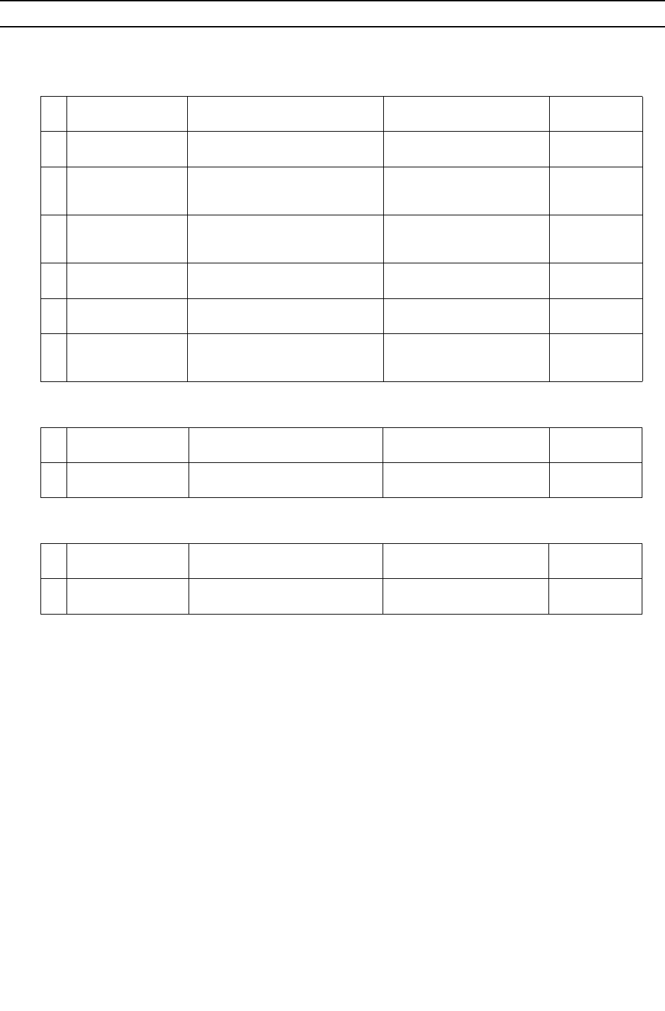
[4] Sample System Connection
Examples of typical system connection are shown on pages [5] to [7].
Refer to the Installation Manual that came with each device or controller for details.
(1) An example of a system to which an MA remote controller is connected
(2) An example of a system to which an ME remote controller is connected
(3) An example of a system to which both MA remote controller and ME remote controller are connected
System
configuration Connection to the system controller Address start up for indoor
and heat source units Notes
1System with one heat
source unit NO Automatic
address setup
2System with one heat
source unit NO Manual
address setup
Connection of
multiple LOSS-
NAY units
3
Grouping of units in a
system with multiple
heat source units
NO Manual
address setup
4System with one heat
source unit
With connection to transmission line
for centralized control
Manual
address setup
5System with one heat
source unit
With connection to indoor-heat
source transmission line
Manual
address setup
6System with one heat
source unit
With connection to transmission line
for centralized control
Manual
address setup
Connection of
multiple LOSS-
NAY units
System
configuration Connection to the system controller Address start up for indoor
and heat source units Notes
1System with one heat
source unit
With connection to transmission line
for centralized control
Manual
address setup
System
configuration Connection to the system controller Address start up for indoor
and heat source units Notes
1System with one heat
source unit
With connection to transmission
line for centralized control
Manual
address setup
[ II Restrictions ]
27- 27 -
HWE09080 GB
[5] An Example of a System to which an MA Remote Controller is connected
1. System with one heat source unit (automatic address setup for both indoor and heat source units) <PQHY>
(1) Sample control wiring
(2) Cautions
1) ME remote controller and MA remote controller cannot
both be connected to the same group of indoor units.
2) No more than 2 MA remote controllers can be connected
to a group of indoor units.
3) A transmission booster is required in a system to which
more than 32 indoor units (26 units if one or more indoor
units of the 72 model or above is connected) are con-
nected.
4) Automatic address setup is not available if start-stop in-
put (CN32, CN51, CN41) is used for a group operation of
indoor units. Refer to "[5] 2. Manual address setup for
both indoor and heat source units".(page 29)
5) To connect more than 2 LOSSNAY units to indoor units
in the same system, refer to the next section "[5] 2. An
example of a system with one heat source unit to which
2 or more LOSSNAY units are connected".(page 29)
(3) Maximum allowable length
1) Indoor-heat source transmission line
Maximum distance (1.25mm2 [AWG16] or larger)
L1 +L2+L3+L4 200m[656ft]
L1 +L2+L11+L12+L13 200m[656ft]
2) Transmission line for centralized control
No connection is required.
3) MA remote controller wiring
Maximum overall line length
(0.3 to 1.25mm2 [AWG22 to 16])
m1 200m [656ft]
m2+m3 200m [656ft]
m4+m5 200m [656ft]
IC
TB5
S
TB
15
1 2
00
IC
TB5
S
TB
15
1 2
00
A B
MA
A B
MA
A B
RC
LC
TB5
S
00
IC
TB5
M1 M2 M1 M2 M1 M2
M1 M2 M1 M2 M1 M2
S 1 2
TB
15
IC
TB5
S
TB
15
1 2
00 00
IC
TB5
S
TB
15
1 2
00
A B
MA
A B
MA
A B
MA
A B
MA
m1
L11
m2
L3 L4
L12 L13
m3
m5
m4
Interlock operation with
the ventilation unit
TB3
00 00
TB7
S
TB3
00
TB7
M1 M2 M1 M2 M1 M2 M1 M2 M1 M2 M1 M2
S
TB3 TB7
S
OC
OS1 OS2
Leave the male
connector on
CN41 as it is.
SW2-1 OFF
Leave the male
connector on
CN41 as it is.
SW2-1 OFF
Leave the male
connector on
CN41 as it is.
SW2-1 OFF
Group Group
Group Group
L2 L1
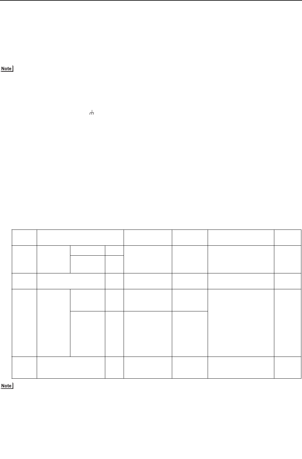
- 28 -
[ II Restrictions ]
GBHWE09080
(4) Wiring method
1) Indoor-heat source transmission line
Daisy-chain terminals M1 and M2 on the terminal block
for indoor-heat source transmission line (TB3) on the
heat source units (OC, OS1, OS2) (Note 1), and termi-
nals M1 and M2 on the terminal block for indoor-heat
source transmission line (TB5) on each indoor unit (IC).
(Non-polarized two-wire)
Only use shielded cables.
The heat source units in the same refrigerant circuit are
automatically designated as OC, OS1, and OS2 in the
order of capacity from large to small (if two or more units
have the same capacity, in the order of address from
small to large).
Shielded cable connection
Daisy-chain the ground terminal ( ) on the heat source
units (OC, OS1, OS2), and the S terminal on the terminal
block (TB5) on the indoor unit (IC) with the shield wire of
the shielded cable.
2) Transmission line for centralized control
No connection is required.
3) MA remote controller wiring
Connect terminals 1 and 2 on the terminal block for MA
remote controller line (TB15) on the indoor unit (IC) to the
terminal block on the MA remote controller (MA). (Non-
polarized two-wire)
When 2 remote controllers are connected to the sys-
tem
When 2 remote controllers are connected to the system,
connect terminals 1 and 2 of the terminal block (TB15) on
the indoor unit (IC) to the terminal block on the two MA
remote controllers.
Set one of the MA remote controllers to sub. (Refer to
MA remote controller function selection or the installation
manual for the MA remote controller for the setting meth-
od.)
Group operation of indoor units
To perform a group operation of indoor units (IC), daisy-
chain terminals 1 and 2 on the terminal block (TB15) on
all indoor units (IC) in the same group, and then connect
terminals 1 and 2 on the terminal block (TB15) on the in-
door unit on one end to the terminal block on the MA re-
mote controller. (Non-polarized two-wire)
When performing a group operation of indoor units that
have different functions, "Automatic indoor-heat source
address setup" is not available.
4) LOSSNAY connection
Connect terminals M1 and M2 on the terminal block
(TB5) on the indoor unit (IC) to the appropriate terminals
on the terminal block (TB5) on LOSSNAY (LC). (Non-po-
larized two-wire)
Interlock operation setting with all the indoor units in the
same system will automatically be made. (It is required
that the Lossnay unit be turned on before the heat source
unit.)
Refer to "[5] 2. Manual address setup for both indoor and
heat source units" in the following cases: performing an
interlock operation of part of the indoor units in the sys-
tem with a LOSSNAY unit, using LOSSNAY alone with-
out interlocking it with any units, performing an interlock
operation of more than 16 indoor units with a LOSSNAY
unit, or connecting two or more LOSSNAY units to indoor
units in the same system.
5) Switch setting
No address settings required.
(5) Address setting method
The heat source units in the same refrigerant circuit are automatically designated as OC, OS1, and OS2.
Proce-
dures Unit or controller Address setting
range
Setting
method Notes Factory
setting
1 Indoor unit Main unit IC No settings re-
quired.
- To perform a group opera-
tion of indoor units that
have different functions,
refer to [5] 2.(page 29)
00
Sub unit IC
2 LOSSNAY LC No settings re-
quired.
-00
3MA
remote con-
troller
Main
remote con-
troller
MA No settings re-
quired.
-Main
Sub
remote con-
troller
MA Sub
remote controller
Settings to
be made ac-
cording to
the remote
controller
function se-
lection
4 Heat source unit (Note) OC
OS1
OS2
No settings re-
quired.
-00
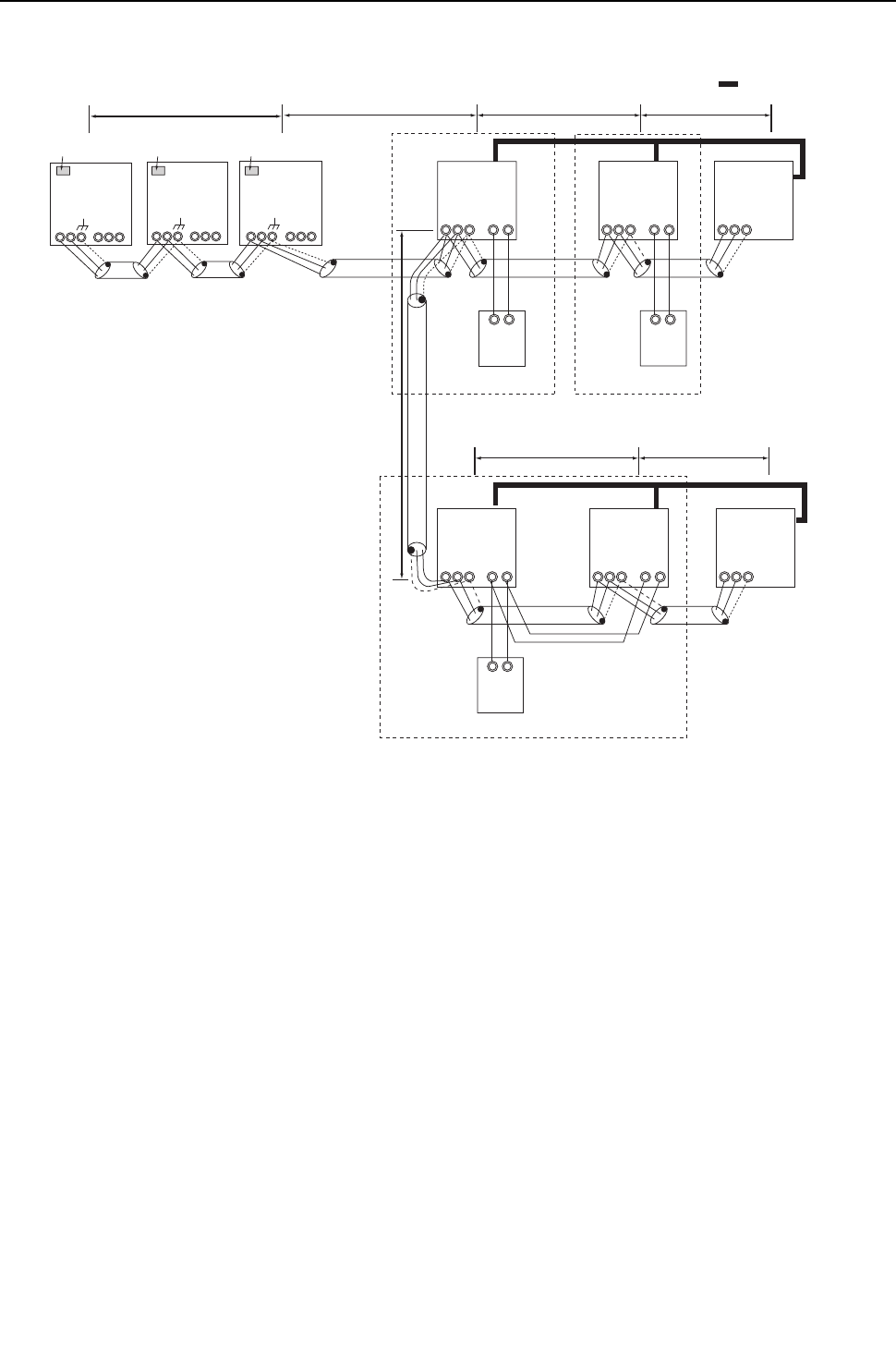
[ II Restrictions ]
29- 29 -
HWE09080 GB
2. An example of a system with one heat source unit to which 2 or more LOSSNAY units are connected
(manual address setup for both indoor and heat source units) <PQHY>
(1) Sample control wiring
(2) Cautions
1) ME remote controller and MA remote controller cannot
both be connected to the same group of indoor units.
2) No more than 2 MA remote controllers can be connected
to a group of indoor units.
3) A transmission booster is required in a system to which
more than 32 indoor units (26 units if one or more indoor
units of the 72 model or above is connected) are con-
nected.
(3) Maximum allowable length
1) Indoor-heat source transmission line
Same as [5] 1.
2) Transmission line for centralized control
No connection is required.
3) MA remote controller wiring
Same as [5] 1.
L2
TB3
51 52
TB7
S
TB3 TB7
S
IC
TB5
S
TB
15
1 2
01
IC
TB5
S
TB
15
1 2
02
A B
MA
A B
MA
LC
TB5
S
05
IC
TB5
S 1 2
TB
15
IC
TB5
S
TB
15
1 2
04 03
LC
TB5
S
06
A B
MA
Group Group
Group
M1 M2 M1 M2 M1 M2
M1 M2 M1 M2 M1 M2
L11
L3 L4
L12 L13
53
TB7
M1 M2 M1 M2 M1 M2 M1 M2 M1 M2 M1 M2
S
TB3
L1
OC OS1 OS2
Leave the male
connector on
CN41 as it is.
SW2-1 OFF
Leave the male
connector on
CN41 as it is.
SW2-1 OFF
Leave the male
connector on
CN41 as it is.
SW2-1 OFF
Interlock operation with
the ventilation unit

- 30 -
[ II Restrictions ]
GBHWE09080
(4) Wiring method
1) Indoor-heat source transmission line
Same as [5] 1.
Shielded cable connection
Same as [5] 1.
2) Transmission line for centralized control
No connection is required.
3) MA remote controller wiring
Same as [5] 1.
When 2 remote controllers are connected to the sys-
tem
Same as [5] 1.
Group operation of indoor units
Same as [5] 1.
4) LOSSNAY connection
Connect terminals M1 and M2 on the terminal block
(TB5) on the indoor unit (IC) to the appropriate terminals
on the terminal block (TB5) on LOSSNAY (LC). (Non-po-
larized two-wire)
Interlock setting between the indoor units and LOSS-
NAY units must be entered on the remote controller. (Re-
fer to "IV [3] Interlock Settings via the MA Remote
Controller" or the installation manual for the MA remote
controller for the setting method.)
5) Switch setting
Address setting is required as follows.
(5) Address setting method
The heat source units in the same refrigerant circuit are automatically designated as OC, OS1, and OS2.
Proce-
dures Unit or controller
Address
setting
range
Setting method Notes Factory
setting
1 Indoor unit Main
unit
IC 01 to 50 Assign the smallest ad-
dress to the main unit in the
group.
To perform a group opera-
tion of indoor units that
have different functions,
designate the indoor unit
in the group with the great-
est number of functions as
the main unit.
00
Sub unit Assign sequential numbers
starting with the address of
the main unit in the same
group +1. (Main unit ad-
dress +1, main unit ad-
dress +2, main unit
address +3, etc.)
2 LOSSNAY LC 01 to 50 Assign an arbitrary but
unique address to each of
these units after assigning
an address to all indoor
units.
None of these addresses
may overlap any of the in-
door unit addresses.
00
3MA
remote con-
troller
Main
remote
control-
ler
MA No
settings re-
quired.
-Main
Sub
remote
control-
ler
MA Sub
remote
controller
Settings to be made ac-
cording to the remote con-
troller function selection
4 Heat source unit OC
OS1
OS2
51 to 100 Assign sequential address
to the heat source units in
the same refrigerant circuit.
The heat source units are
automatically designated
as OC, OS1, and
OS2.(Note)
To set the address to 100,
set the rotary switches to
50.
00
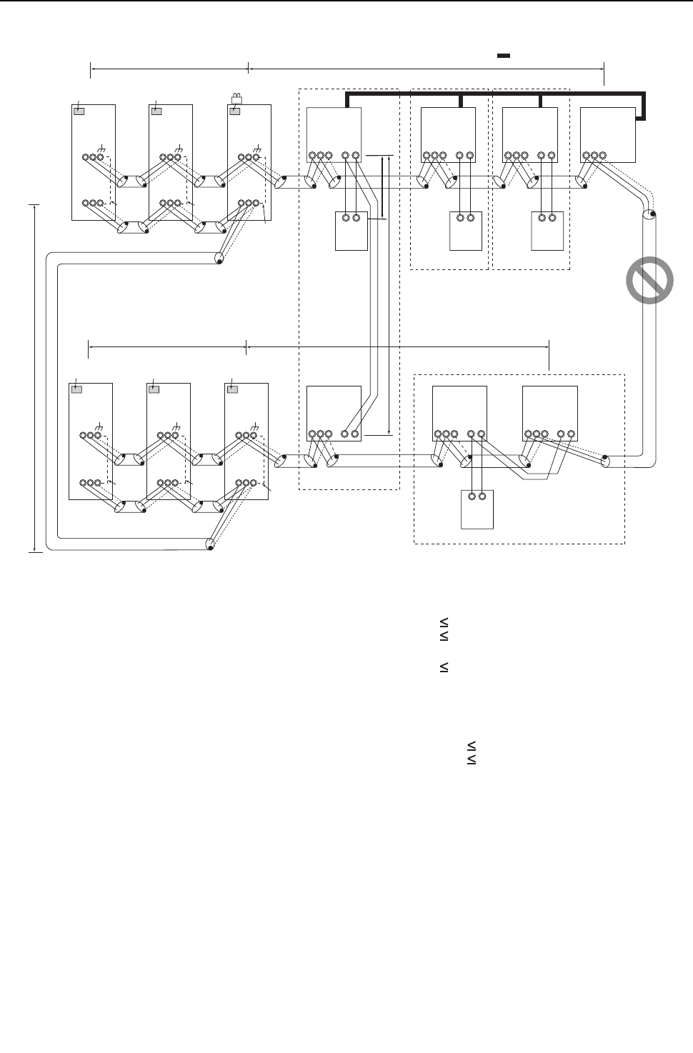
[ II Restrictions ]
31- 31 -
HWE09080 GB
3. Group operation of units in a system with multiple heat source units <PQHY>
(1) Sample control wiring
(2) Cautions
1) ME remote controller and MA remote controller cannot
both be connected to the same group of indoor units.
2) No more than 2 MA remote controllers can be connected
to a group of indoor units.
3) Do not connect the terminal blocks (TB5) on the indoor
units that are connected to different heat source units
with each other.
4) Replacement of male power jumper connector (CN41)
must be performed only on one of the heat source units.
5) Provide grounding to S terminal on the terminal block for
transmission line for centralized control (TB7) on only
one of the heat source units.
6) A transmission booster is required in a system to which
more than 32 indoor units (26 units if one or more indoor
units of the 72 model or above is connected) are con-
nected.
(3) Maximum allowable length
1) Indoor-heat source transmission line
Maximum distance (1.25mm2 [AWG16] or larger)
L11+L12 200m [656ft]
L21+L22 200m [656ft]
2) Transmission line for centralized control
L31+L21 200m [656ft]
3) MA remote controller wiring
Same as [5] 1.
4) Maximum line distance via heat source unit
(1.25mm2 [AWG16] or larger)
L12+L31+L22 500m [1640ft]
L11+L31+L21 500m [1640ft]
IC
TB5
S
TB
15
1 2
01
IC
TB5
S
TB
15
1 2
03
A B
MA
A B
MA
LC
TB5
S
07
IC
TB5
S 1 2
TB
15
IC
TB5
S
TB
15
1 2 1 2
04 02
IC
TB5 TB15
S
05
A B
MA
IC
TB5
S
TB
15
1 2
06
A B
MA
Group
Group Group
Group
M1 M2 M1 M2 M1 M2 M1 M2
M1 M2 M1 M2
M1 M2
m2
m3
Interlock operation with
the ventilation unit
L12
L22
L11
L21
OC
TB3
TB7
S
51
To be connected
To be left
unconnected
To be left
unconnected
OS1
TB3
TB7
S
52
OS2
TB3
TB7
M1 M2 M1 M2 M1 M2
M1 M2 M1 M2 M1 M2
S
53
OC
TB3
TB7
S
54
OS1
TB3
TB7
S
55
OS2
TB3
TB7
M1 M2 M1 M2 M1 M2
M1 M2 M1 M2 M1 M2
S
56
L31
Leave the male
connector on
CN41 as it is.
SW2-1 OFF
Leave the male
connector on
CN41 as it is.
SW2-1 OFF
Leave the male
connector on
CN41 as it is.
SW2-1 OFF
Leave the male
connector on
CN41 as it is.
SW2-1 OFF
Leave the male
connector on
CN41 as it is.
SW2-1 OFF
SW2-1 OFF
Move the male connector
from CN41 to CN40.
To be left
unconnected
To be left
unconnected
To be left
unconnected
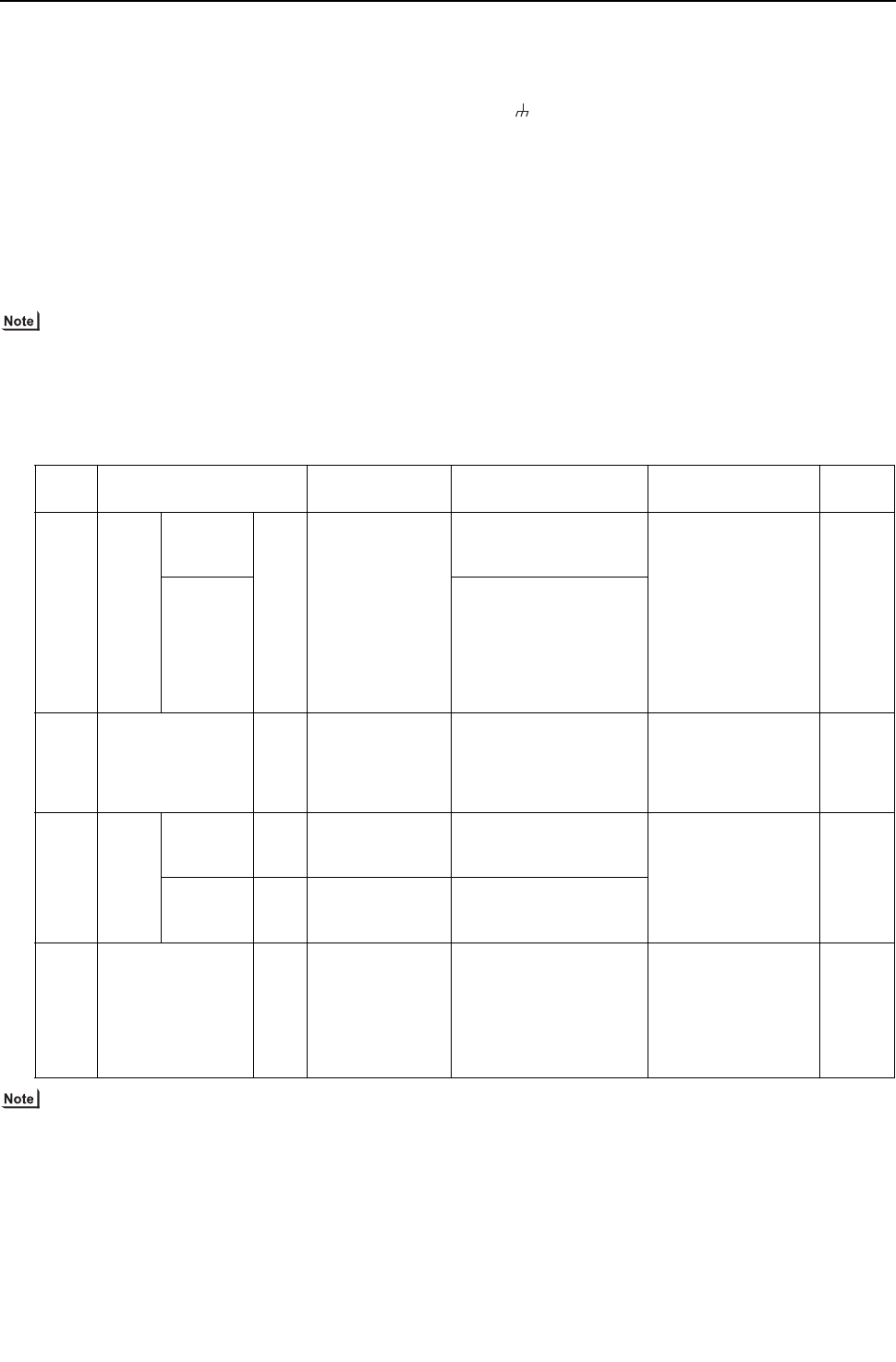
- 32 -
[ II Restrictions ]
GBHWE09080
(4) Wiring method
1) Indoor-heat source transmission line
Same as [5] 1.
Only use shielded cables.
Shielded cable connection
Same as [5] 1.
2) Transmission line for centralized control
Daisy-chain terminals M1 and M2 on the terminal block
for transmission line for centralized control (TB7) on the
heat source units (OC) in different refrigerant circuits and
on the OC, OS1, and OS2 in the same refrigerant circuit
If a power supply unit is not connected to the transmis-
sion line for centralized control, replace the power jump-
er connector on the control board from CN41 to CN40 on
only one of the heat source units.
The heat source units in the same refrigerant circuit are
automatically designated as OC, OS1, and OS2 in the
order of capacity from large to small (if two or more units
have the same capacity, in the order of address from
small to large).
Only use shielded cables.
Shielded cable connection
Daisy-chain the S terminal on the terminal block (TB7) on
the heat source units (OC, OS1, OS2) with the shield
wire of the shielded cable. Short-circuit the earth terminal
( ) and the S terminal on the terminal block (TB7) on
the heat source unit whose power jumper connector is
mated with CN40.
3) MA remote controller wiring
Same as [5] 1.
When 2 remote controllers are connected to the sys-
tem
Same as [5] 1.
Group operation of indoor units
Same as [5] 2.
4) LOSSNAY connection
Same as [5] 2.
5) Switch setting
Address setting is required as follows.
(5) Address setting method
The heat source units in the same refrigerant circuit are automatically designated as OC, OS1, and OS2.
Proce-
dures Unit or controller Address setting
range Setting method Notes Factory
setting
1 Indoor
unit
Main unit IC 01 to 50 Assign the smallest ad-
dress to the main unit in
the group.
To perform a group
operation of indoor
units that have differ-
ent functions, desig-
nate the indoor unit in
the group with the
greatest number of
functions as the main
unit.
00
Sub unit Assign sequential num-
bers starting with the ad-
dress of the main unit in
the same group +1. (Main
unit address +1, main unit
address +2, main unit ad-
dress +3, etc.)
2 LOSSNAY LC 01 to 50 Assign an arbitrary but
unique address to each of
these units after assigning
an address to all indoor
units.
None of these ad-
dresses may overlap
any of the indoor unit
addresses.
00
3MA
re-
mote
con-
troller
Main
remote
controller
MA No
settings required.
-Main
Sub
remote
controller
MA Sub
remote controller
Settings to be made ac-
cording to the remote con-
troller function selection
4 Heat source unit OC
OS1
OS2
51 to 100 Assign sequential address
to the heat source units in
the same refrigerant cir-
cuit. The heat source
units are automatically
designated as OC, OS1,
and OS2. (Note)
To set the address to
100, set the rotary
switches to 50.
00
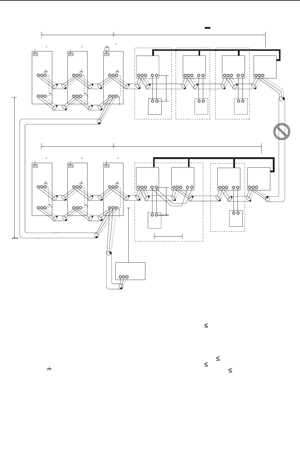
[ II Restrictions ]
33- 33 -
HWE09080 GB
4. A system in which a system controller is connected to the transmission line for centralized control and which is pow-
ered from a heat source unit <PQHY>
(1) Sample control wiring
(2) Cautions
1) ME remote controller and MA remote controller cannot
both be connected to the same group of indoor units.
2) No more than 2 MA remote controllers can be connected
to a group of indoor units.
3) Do not connect the terminal blocks (TB5) on the indoor
units that are connected to different heat source units
with each other.
4) Replacement of male power jumper connector (CN41)
must be performed only on one of the heat source units.
5) Short-circuit the shield terminal (S terminal) and the
earth terminal ( ) on the terminal block for transmission
line for centralized control (TB7) on the heat source unit
whose power jumper connector is mated with CN40.
6) A transmission booster is required in a system to which
more than 32 indoor units (26 units if one or more indoor
units of the 72 model or above is connected) are con-
nected.
7) When a power supply unit is connected to the transmis-
sion line for centralized control, leave the power jumper
connector on CN41 as it is (factory setting).
(3) Maximum allowable length
1) Indoor-heat source transmission line
Same as [5] 3.
2) Transmission line for centralized control
L31+L32(L21) 200m [656ft]
3) MA remote controller wiring
Same as [5] 1.
4) Maximum line distance via heat source unit
(1.25mm2 [AWG16] or larger)
L32+L31+L12(L11) 500m [1640ft]
L32+L22(L21) 500m [1640ft]
L12(L11)+L31+L22(L21) 500m[1640ft]
IC
TB5
S
TB
15
1 2
01
IC
TB5
S
TB
15
1 2
02
A B
MA
A B
MA
LC
TB5
S
07
IC
TB5
S 1 2
TB
15
IC
TB5
S
TB
15
1 2
05 04
LC
TB5
S
08
IC
TB5
S
TB
15
1 2
03
A B
MA
IC
TB5
S
TB
15
1 2
06
A B
MA
A B
MA
M1 M2 M1 M2 M1 M2 M1 M2
M1 M2 M1 M2 M1 M2 M1 M2
L12 L11
L22 L21
m3
L31
A B S
L32
Note1
System controller
OC
TB3
TB7
S
51
To be connected
To be left
unconnected
To be left
unconnected
m2 m1
OS1
TB3
TB7
S
52
OS2
TB3
TB7
M1 M2 M1 M2 M1 M2
M1 M2 M1 M2 M1 M2
S
53
OC
TB3
TB7
S
54
OS1
TB3
TB7
S
55
OS2
TB3
TB7
M1 M2 M1 M2 M1 M2
M1 M2 M1 M2 M1 M2
S
56
Leave the male
connector on
CN41 as it is.
SW2-1 OFF ON
Leave the male
connector on
CN41 as it is.
SW2-1 OFF ON
Leave the male
connector on
CN41 as it is.
SW2-1 OFF ON
Leave the male
connector on
CN41 as it is.
SW2-1 OFF ON
Leave the male
connector on
CN41 as it is.
SW2-1 OFF ON
SW2-1 OFF ON
Group Group Group
Group Group
Interlock operation with
the ventilation unit
Note1 When only the LM adapter is connected,
leave SW2-1 to OFF (as it is).
Note2 LM adapters require the power supply
capacity of single-phase AC 208/230V.
To be left
unconnected
To be left
unconnected
To be left
unconnected
Move the male connector
from CN41 to CN40.
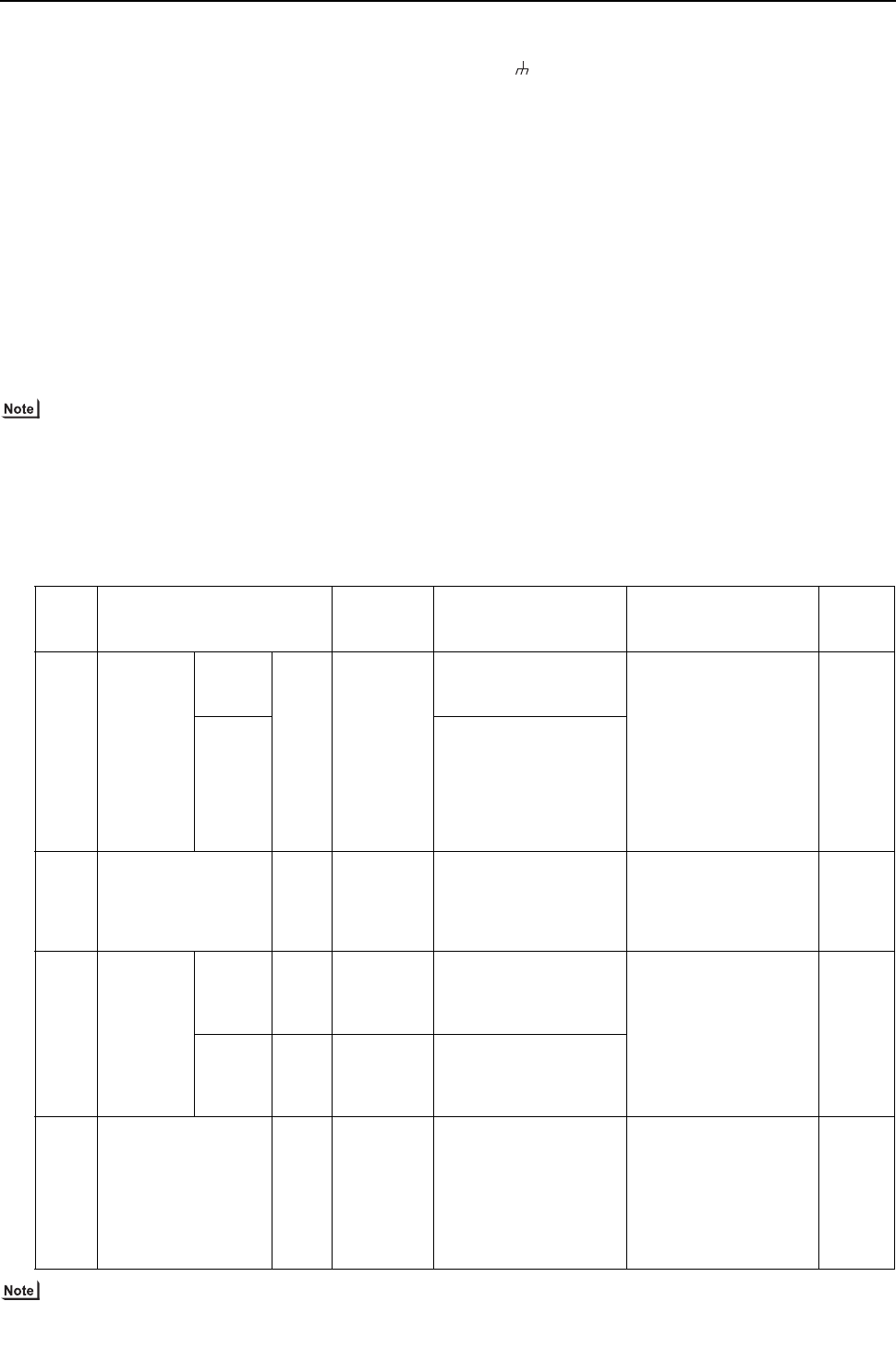
- 34 -
[ II Restrictions ]
GBHWE09080
(4) Wiring method
1) Indoor-heat source transmission line
Same as [5] 1.
Only use shielded cables.
Shielded cable connection
Same as [5] 1.
2) Transmission line for centralized control
Daisy-chain terminals A and B on the system controller,
terminals M1 and M2 on the terminal block for transmis-
sion line for centralized control (TB7) on the heat source
units (OC) in different refrigerant circuits and on the heat
source units (OC, OS1, and OS2) in the same refrigerant
circuit.
If a power supply unit is not connected to the transmis-
sion line for centralized control, replace the power jump-
er connector on the control board from CN41 to CN40 on
only one of the heat source units.
If a system controller is connected, set the central control
switch (SW2-1) on the control board of all heat source
units to "ON."
The heat source units in the same refrigerant circuit are
automatically designated as OC, OS1, and OS2 in the
order of capacity from large to small (if two or more units
have the same capacity, in the order of address from
small to large).
Only use shielded cables.
Shielded cable connection
Daisy-chain the S terminal on the terminal block (TB7) on
the heat source units (OC, OS1, OS2) with the shield
wire of the shielded cable. Short-circuit the earth terminal
( ) and the S terminal on the terminal block (TB7) on
the heat source unit whose power jumper connector is
mated with CN40.
3) MA remote controller wiring
Same as [5] 1.
When 2 remote controllers are connected to the sys-
tem
Same as [5] 1.
Group operation of indoor units
Same as [5] 1.
4) LOSSNAY connection
Connect terminals M1 and M2 on the terminal block
(TB5) on the indoor unit (IC) to the appropriate terminals
on the terminal block for indoor-heat source transmission
line (TB5) on LOSSNAY (LC). (Non-polarized 2-core ca-
ble)
Indoor units must be interlocked with the LOSSNAY unit
using the system controller. (Refer to the operation man-
ual for the system controller for the setting method.) In-
terlock setting from the remote controller is required if the
ON/OFF remote controller alone or the LM adapter alone
is connected.
5) Switch setting
Address setting is required as follows.
(5) Address setting method
The heat source units in the same refrigerant circuit are automatically designated as OC, OS1, and OS2.
Proce-
dures Unit or controller
Address
setting
range
Setting method Notes Factory
setting
1 Indoor unit Main unit IC 01 to 50 Assign the smallest ad-
dress to the main unit in
the group.
To perform a group oper-
ation of indoor units that
have different functions,
designate the indoor unit
in the group with the
greatest number of func-
tions as the main unit.
00
Sub unit Assign sequential num-
bers starting with the ad-
dress of the main unit in
the same group +1. (Main
unit address +1, main unit
address +2, main unit ad-
dress +3, etc.)
2 LOSSNAY LC 01 to 50 Assign an arbitrary but
unique address to each of
these units after assign-
ing an address to all in-
door units.
None of these addresses
may overlap any of the in-
door unit addresses.
00
3MA
remote con-
troller
Main
remote
control-
ler
MA No
settings re-
quired.
- Enter the same indoor
unit group settings on the
system controller as the
ones that were entered
on the MA remote con-
troller.
Main
Sub
remote
control-
ler
MA Sub
remote con-
troller
Settings to be made ac-
cording to the remote
controller function selec-
tion
4 Heat source unit OC
OS1
OS2
51 to 100 Assign sequential ad-
dress to the heat source
units in the same refriger-
ant circuit.
The heat source units are
automatically designated
as OC, OS1, and
OS2.(Note)
To set the address to
100, set the rotary switch-
es to 50.
00
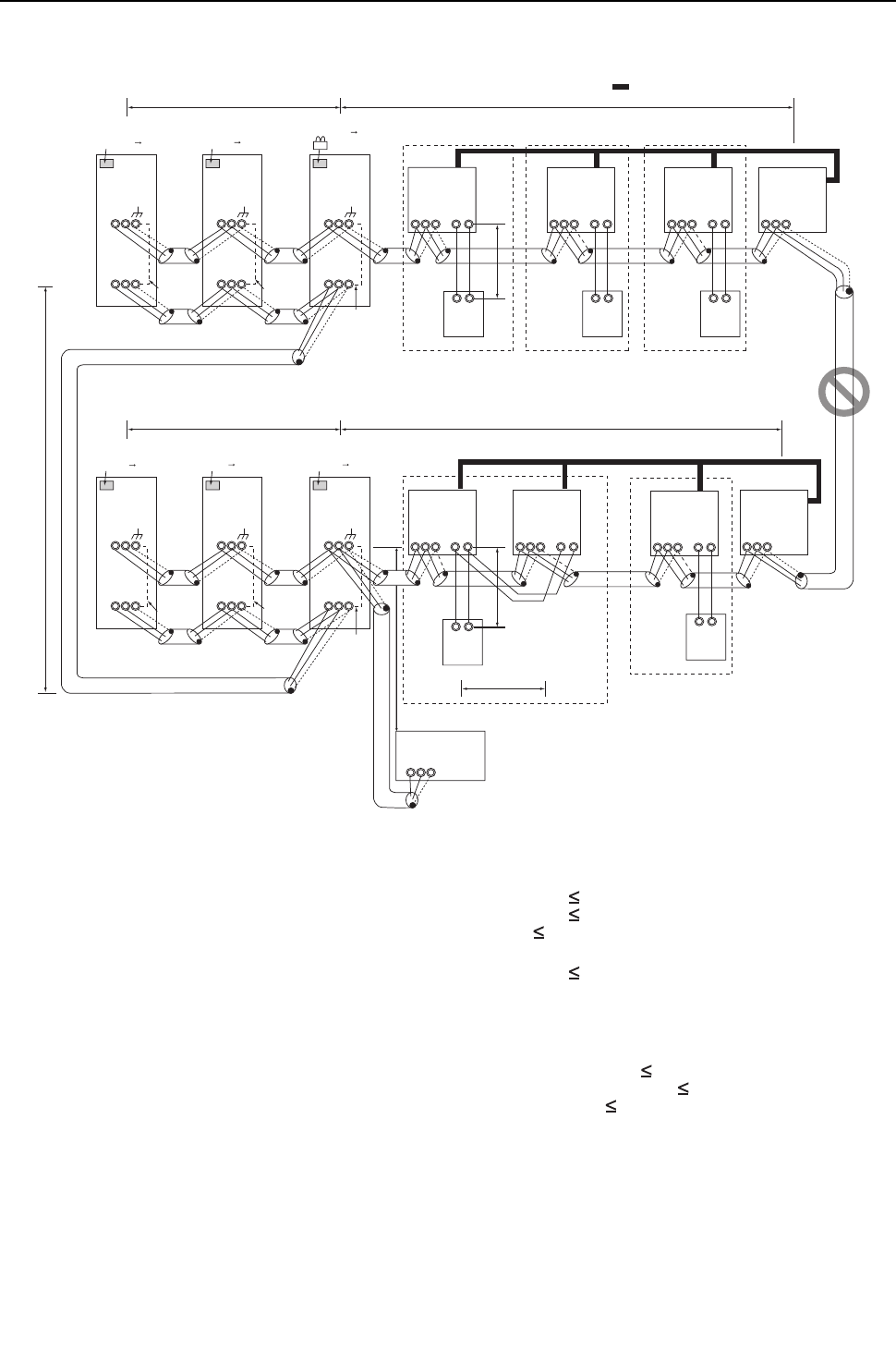
[ II Restrictions ]
35- 35 -
HWE09080 GB
5. An example of a system in which a system controller is connected to the indoor-heat source transmission line (ex-
cept LM adapter) <PQHY>
(1) Sample control wiring
(2) Cautions
1) ME remote controller and MA remote controller cannot
both be connected to the same group of indoor units.
2) No more than 2 MA remote controllers can be connected
to a group of indoor units.
3) Do not connect the terminal blocks (TB5) on the indoor
units that are connected to different heat source units
with each other.
4) Replacement of male power jumper connector (CN41)
must be performed only on one of the heat source units.
5) Provide grounding to S terminal on the terminal block for
transmission line for centralized control (TB7) on only
one of the heat source units.
6) A maximum of 3 system controllers can be connected to
the indoor-heat source transmission line, with the excep-
tion that only one G(B)-50A may be connected.
7) When the total number of indoor units exceeds 26, it may
not be possible to connect a system controller on the in-
door-heat source transmission line.
8) In a system to which more than 18 indoor units including
one or more indoor units of 72 model or above are con-
nected, there may be cases in which the system control-
ler cannot be connected to the indoor-heat source
transmission line.
(3) Maximum allowable length
1) Indoor-heat source transmission line
Maximum distance (1.25mm2 [AWG16] or larger)
L11+L12 200m [656ft]
L21+L22 200m [656ft]
L25 200m [656ft]
2) Transmission line for centralized control
L31+L21 200m [656ft]
3) MA remote controller wiring
Same as [5] 1.
4) Maximum line distance via heat source unit
(1.25mm2 [AWG16] or larger)
L25+L31+L12(L11) 500m [1640ft]
L12(L11)+L31+L22(L21) 500m [1640ft]
L25+L22(L21) 500m [1640ft]
IC
TB5
S
TB
15
1 2
01
IC
TB5
S
TB
15
1 2
02
A B
MA
A B
MA
LC
TB5
S
07
IC
TB5
S 1 2
TB
15
IC
TB5
S
TB
15
1 2
05 04
LC
TB5
S
08
IC
TB5
S
TB
15
1 2
03
A B
MA
IC
TB5
S
TB
15
1 2
06
A B
MA
A B
MA
M1 M2 M1 M2 M1 M2 M1 M2
M1 M2
M1 M2
M1 M2 M1 M2
L12 L11
L22 L21
m3
OC
TB3
TB7
S
51
m2 m1
OS1
TB3
TB7
S
52
OS2
TB3
TB7
M1 M2 M1 M2 M1 M2
M1 M2 M1 M2 M1 M2
S
53
OC
TB3
TB7
S
54
OS1
TB3
TB7
S
55
OS2
TB3
TB7
M1 M2 M1 M2 M1 M2
M1 M2 M1 M2 M1 M2
S
56
L31
A B S
L25
Note1 LM adapters cannot be connected to the
indoor-heat source transmission line.
Note1
System controller
SW2-1 OFF ON
SW2-1 OFF ON
Leave the male
connector on
CN41 as it is.
SW2-1 OFF ON
Leave the male
connector on
CN41 as it is.
Move the male connector
from CN41 to CN40.
SW2-1 OFF ON
Leave the male
connector on
CN41 as it is.
SW2-1 OFF ON
Leave the male
connector on
CN41 as it is.
SW2-1 OFF ON
Leave the male
connector on
CN41 as it is.
Group Group Group
Group Group
Interlock operation with
the ventilation unit
To be left
unconnected
To be left
unconnected
To be left
unconnected
To be left
unconnected
To be left
unconnected
To be connected
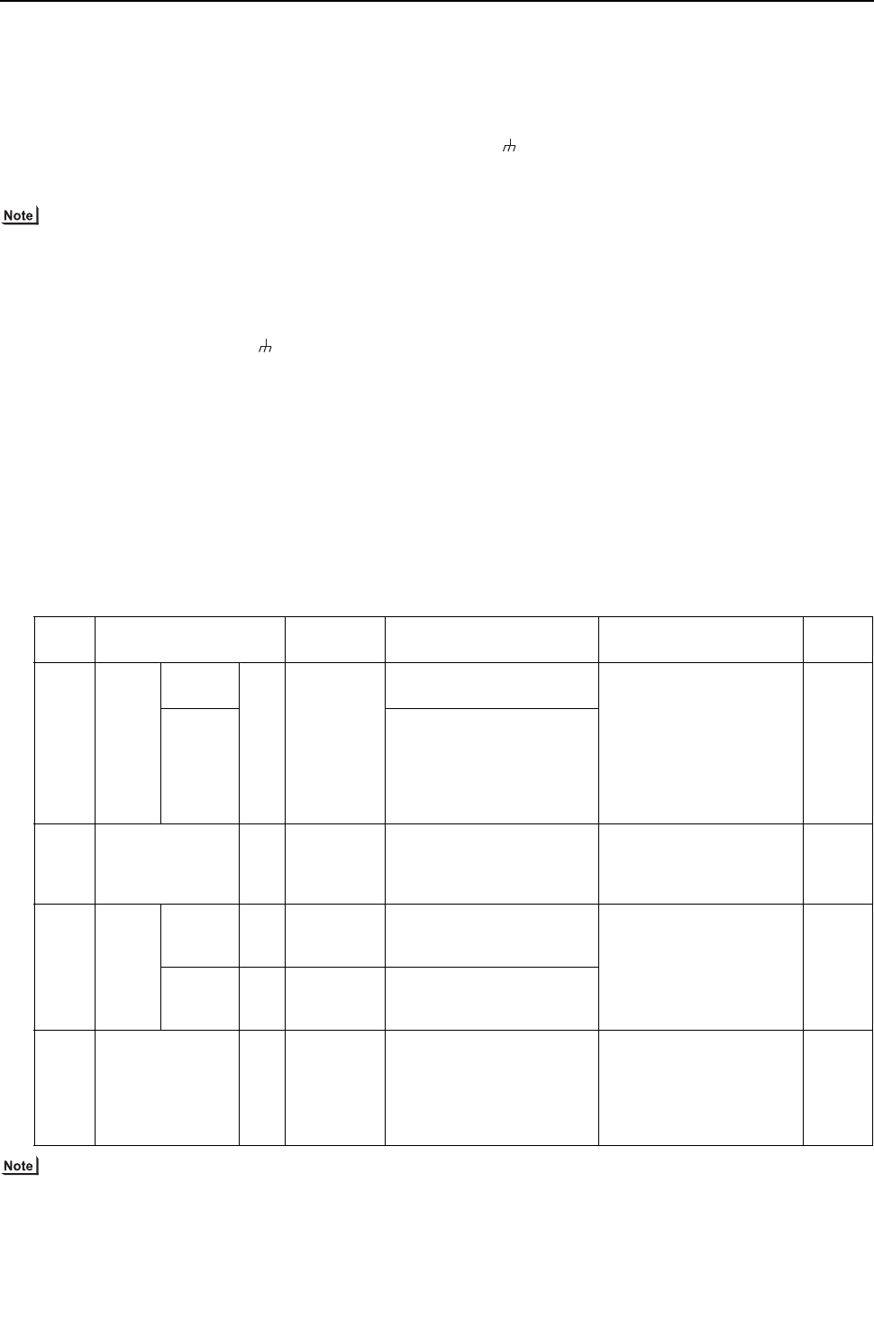
- 36 -
[ II Restrictions ]
GBHWE09080
(4) Wiring method
1) Indoor-heat source transmission line
Daisy-chain terminals M1 and M2 on the terminal block
for indoor-heat source transmission line (TB3) on the
heat source units (OC, OS1, OS2) (Note 1), terminals M1
and M2 on the terminal block for indoor-heat source
transmission line (TB5) on each indoor unit (IC), and the
S terminal on the system controller. (Non-polarized two-
wire)
Only use shielded cables.
The heat source units in the same refrigerant circuit are
automatically designated as OC, OS1, and OS2 in the
order of capacity from large to small (if two or more units
have the same capacity, in the order of address from
small to large).
Shielded cable connection
Daisy-chain the ground terminal ( ) on the heat source
units (OC, OS1, OS2), the S terminal on the terminal
block (TB5) on the indoor unit (IC), and the S terminal on
the system controller with the shield wire of the shielded
cable.
2) Transmission line for centralized control
Daisy-chain terminals M1 and M2 on the terminal block
for transmission line for centralized control (TB7) on the
heat source units (OC) in different refrigerant circuits and
on the OC, OS1, and OS2 in the same refrigerant circuit.
If a power supply unit is not connected to the transmis-
sion line for centralized control, replace the power jump-
er connector on the control board from CN41 to CN40 on
only one of the heat source units.
Set the central control switch (SW2-1) on the control
board of all heat source units to "ON."
Only use shielded cables.
Shielded cable connection
Daisy-chain the S terminal on the terminal block (TB7) on
the heat source units (OC, OS1, OS2) with the shield
wire of the shielded cable. Short-circuit the earth terminal
( ) and the S terminal on the terminal block (TB7) on
the heat source unit whose power jumper connector is
mated with CN40.
3) MA remote controller wiring
Same as [5] 1.
When 2 remote controllers are connected to the sys-
tem
Same as [5] 1.
Group operation of indoor units
Same as [5] 1.
4) LOSSNAY connection
Connect terminals M1 and M2 on the terminal block
(TB5) on the indoor units (IC) to the appropriate termi-
nals on the terminal block for indoor-heat source trans-
mission line (TB5) on LOSSNAY (LC). (Non-polarized
two-wire)
Indoor units must be interlocked with the LOSSNAY unit
using the system controller. (Refer to the operation man-
ual for the system controller for the setting method.) In-
terlock setting from the remote controller is required if the
ON/OFF remote controller alone is connected.
5) Switch setting
Address setting is required as follows.
(5) Address setting method
The heat source units in the same refrigerant circuit are automatically designated as OC, OS1, and OS2.
Proce-
dures Unit or controller Address set-
ting range Setting method Notes Factory
setting
1 Indoor
unit
Main unit IC 01 to 50 Assign the smallest address
to the main unit in the group.
To perform a group opera-
tion of indoor units that have
different functions, desig-
nate the indoor unit in the
group with the greatest
number of functions as the
main unit.
00
Sub unit Assign sequential numbers
starting with the address of
the main unit in the same
group +1. (Main unit address
+1, main unit address +2,
main unit address +3, etc.)
2 LOSSNAY LC 01 to 50 Assign an arbitrary but
unique address to each of
these units after assigning an
address to all indoor units.
None of these addresses
may overlap any of the in-
door unit addresses.
00
3MA
remote
control-
ler
Main
remote
controller
MA No
settings re-
quired.
- Enter the same indoor unit
group settings on the sys-
tem controller as the ones
that were entered on the MA
remote controller.
Main
Sub
remote
controller
MA Sub
remote con-
troller
Settings to be made accord-
ing to the remote controller
function selection
4 Heat source unit OC
OS1
OS2
51 to 100 Assign sequential address to
the heat source units in the
same refrigerant circuit.
The heat source units are au-
tomatically designated as
OC, OS1, and OS2. (Note)
To set the address to 100,
set the rotary switches to 50.
00
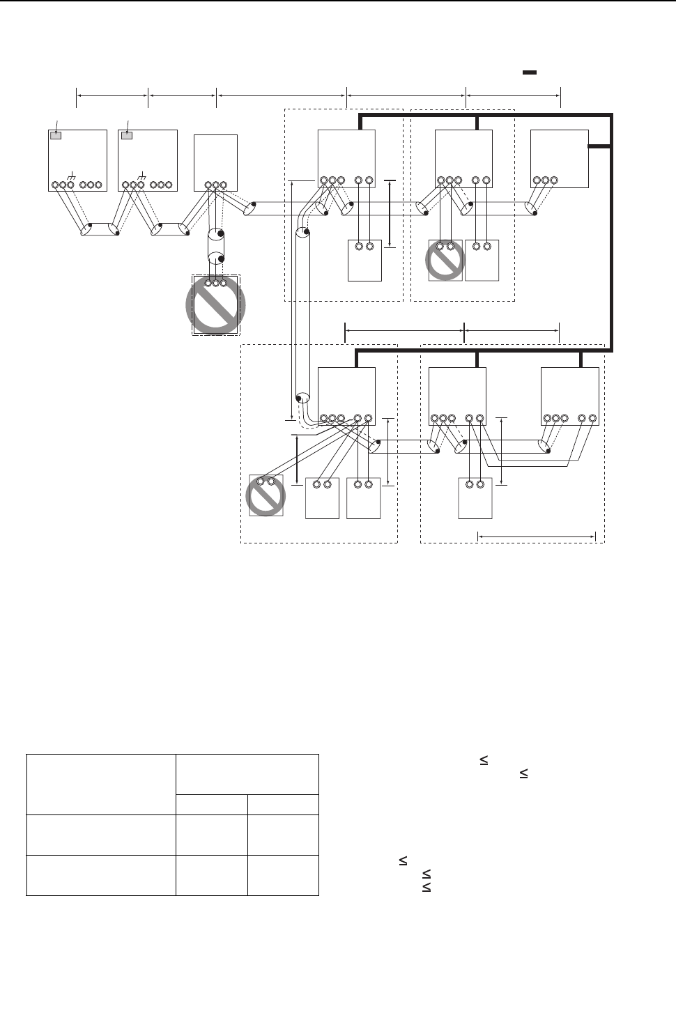
[ II Restrictions ]
37- 37 -
HWE09080 GB
6. System with one heat source unit (automatic address setup for both indoor and heat source units) <PQRY>
(1) Sample control wiring
(2) Cautions
1) ME remote controller and MA remote controller cannot
both be connected to the same group of indoor units.
2) No more than 2 MA remote controllers can be connected
to a group of indoor units.
3) When the number of the connected indoor units is as
shown in the table below, one or more transmission
boosters (sold separately) are required.
To connect two transmission boosters, connect them in
parallel. (Observe the maximum number of connectable
indoor units that are listed in the specifications for each
heat source unit.)
The table above shows the number of transmission
boosters that is required by the system with three BC
controllers. For each BC controller that is subtracted
from the above-mentioned system, two additional indoor
units can be connected.
4) Automatic address setup is not available if start-stop in-
put(CN32, CN51, CN41) is used for a group operation of
indoor units. Refer to "[5] 7. Manual address setup for
both indoor and heat source units"
5) To connect more than 2 LOSSNAY units to indoor units
in the same system, refer to the next section "[5] 7. An
example of a system with one heat source unit to which
2 or more LOSSNAY units are connected".
(3) Maximum allowable length
1) Indoor-heat source transmission line
Maximum distance (1.25mm2 [AWG16] or larger)
L1 +L2+L3+L4+L5 200m[656ft]
L1 +L2+L3+L11+L12+L13 200m[656ft]
2) Transmission line for centralized control
No connection is required.
3) MA remote controller wiring
Maximum overall line length
(0.3 to 1.25mm2 [AWG22 to 16])
m1 200m [656ft]
m2+m3 200m [656ft]
m4+m5 200m [656ft]
IC
TB5
M1
M2
M1
M2
M1
M2
M1
M2
M1
M2
M1
M2
S
TB
15
12
00
IC
TB5
S
TB
15
12
00
A1 B2
MA
A1 B2
MA
A1 B2
RC
LC
TB5
S
00
IC
TB5
S12
TB
15
IC
TB5
S
TB
15
12
0000
IC
TB5
S
TB
15
12
00
A1 B2
MA
A1 B2
MA
A1 B2
MA
GroupGroup
GroupGroup
A1 B2
MA
m1
L11
m2
L4 L5
L12 L13
m3
m5
m4
Interlock operation with
the ventilation unit
*1. When BS is connected to the system,
automatic address setup is not available.
BC
00
OC
00
TB7
M1 M2
S
TB3
OS
00
TB7
M1 M2 M1 M2 M1 M2
S
TB3 TB02
M1 M2
S
*1
BS
TB02
00
S
M1 M2
L3L1 L2
Leave the male
connector on
CN41 as it is.
SW2-1 OFF
Leave the male
connector on
CN41 as it is.
SW2-1 OFF
Number of transmission
booster (sold separately) re-
quired
1 unit 2 units
When the P72 and P96 models
are not included in the connect-
ed indoor units
27 - 50 units -
When the P72 or P96 model is
included in the connected in-
door units
21 - 39 units 40 - 50 units
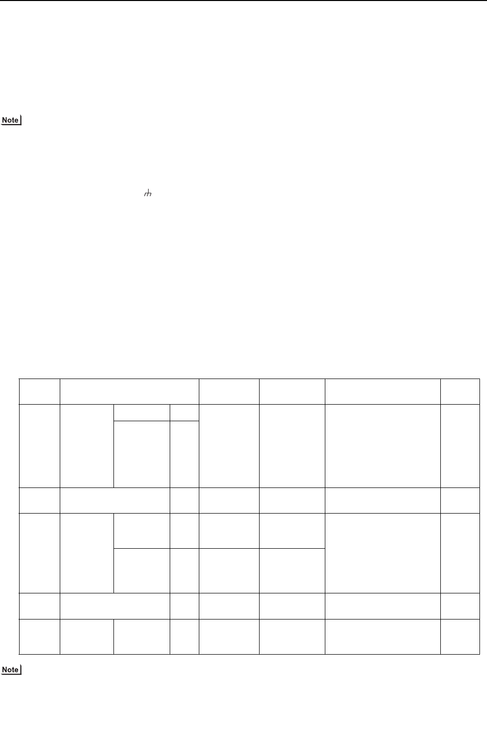
- 38 -
[ II Restrictions ]
GBHWE09080
(4) Wiring method
1) Indoor-heat source transmission line
Daisy-chain terminals M1 and M2 of the terminal block
for indoor-heat source transmission line (TB3) on the
heat source units (OC and OS), of the terminal block for
indoor-heat source transmission line (TB02) on the main
BC controller (BC), and of the terminal block for indoor-
heat source transmission line (TB5) on each indoor unit
(IC). (Non-polarized two-wire)
Only use shielded cables.
The heat source units in the same refrigerant circuit are
automatically designated as OC and OS in the order of
capacity from large to small (if two or more units have the
same capacity, in the order of address from small to
large).
Shielded cable connection
Daisy-chain the ground terminal ( ) on the heat source
units (OC and OS), the S terminal of the terminal block
(TB02) on the BC controller (BC), and the S terminal of
the terminal block (TB5) on the indoor unit (IC) with the
shield of the shielded cable.
2) Transmission line for centralized control
No connection is required.
3) MA remote controller wiring
Connect terminals 1 and 2 on the terminal block for MA
remote controller line (TB15) on the indoor unit (IC) to the
terminal block on the MA remote controller (MA).
(Non-polarized two-wire)
When 2 remote controllers are connected to the sys-
tem
When 2 remote controllers are connected to the system,
connect terminals 1 and 2 of the terminal block (TB15) on
the indoor unit (IC) to the terminal block on the two MA
remote controllers.
Set one of the MA remote controllers as a sub controller.
(Refer to the Instruction Manual for the MA remote con-
troller for the setting method.)
Group operation of indoor units
To perform a group operation of indoor units (IC), daisy-
chain terminals 1 and 2 on the terminal block (TB15) on
all indoor units (IC) in the same group, and then connect
terminals 1 and 2 on the terminal block (TB15) on the in-
door unit on one end to the terminal block on the MA re-
motecontroller. (Non-polarized two-wire)
When performing a group operation of indoor units that
have different functions, "Automatic indoor-heat source
addresssetup" is not available.
4) LOSSNAY connection
Connect terminals M1 and M2 on the terminal
block(TB5) on the indoor unit (IC) to the appropriate ter-
minals on the terminal block (TB5) on LOSSNAY (LC).
(Non-polarized two-wire)
Interlock operation setting with all the indoor units in the
same system will automatically be made. (It is required
that the Lossnay unit be turned on before the heat source
unit.)
When performing an interlocked operation of part of the
indoor units in the system with a LOSSNAY unit, using a
LOSSNAY unit alone without interlocking it with any
units, performing an interlock operation of more than 16
indoor units with a LOSSNAY unit, or connecting two or
more LOSSNAY units to the same refrigerant system,
the automatic address setup function is not available.
5) Switch setting
No address settings required.
(5) Address setting method
The heat source units in the same refrigerant circuit are automatically designated as OC and OS.
They are designated as OC and OS in the descending order of capacity (ascending order of address if the capacities are the
same).
Proce-
dures Unit or controller Address set-
ting range Setting method Notes Factory
setting
1 Indoor unit Main unit IC No settings
required.
- Port number setting is re-
quired
To perform a group opera-
tion of indoor units that fea-
ture different functions, the
automatic IC/OC address
setup function is not avail-
able.
00
Sub unit IC
2 LOSSNAY LC No settings
required.
-00
3MA
remote con-
troller
Main
remote con-
troller
MA No settings
required.
-Main
Sub
remote con-
troller
MA Sub
remote con-
troller
Settings to be
made with the
Sub/Main
switch
4 Heat source unit OC
OS
No settings
required.
-00
5 Auxiliary
heat source
unit
BC
controller
BC No settings
required.
-00
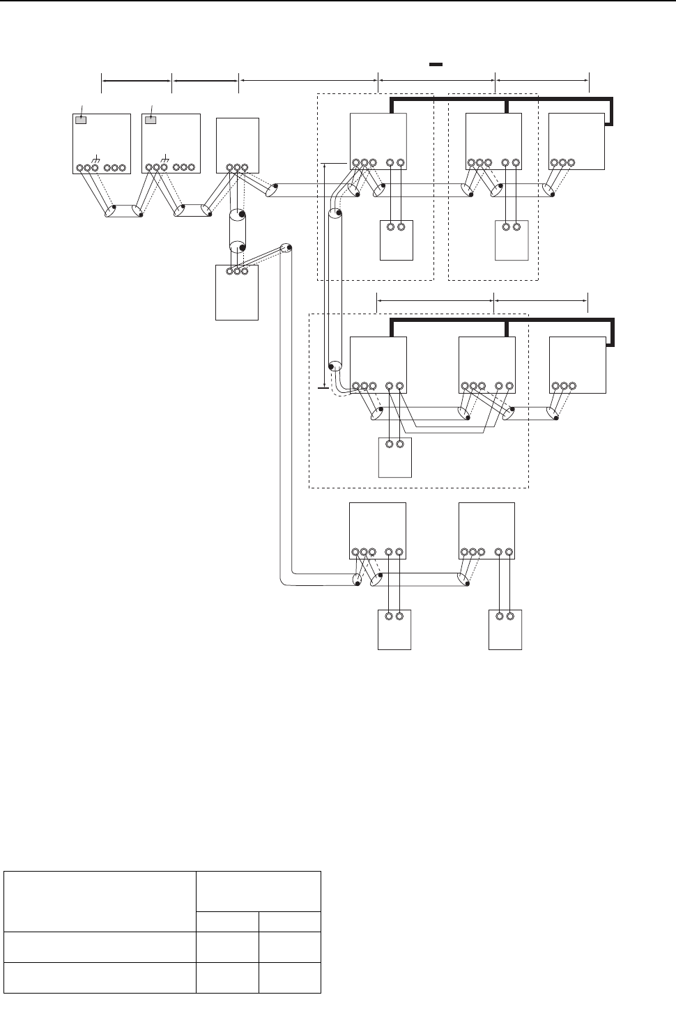
[ II Restrictions ]
39- 39 -
HWE09080 GB
7. An example of a system with one heat source unit to which 2 or more LOSSNAY units are connected
(manual address setup for both indoor and heat source units) <PQRY>
(1) Sample control wiring
(2) Cautions
1) ME remote controller and MA remote controller cannot
both be connected to the same group of indoor units.
2) No more than 2 MA remote controllers can be connected
to a group of indoor units.
3) When the number of the connected indoor units is as
shown in the table below, one or more transmission
boosters (sold separately) are required.
To connect two transmission boosters, connect them in
parallel. (Observe the maximum number of connectable
indoor units that are listed in the specifications for each
heat source unit.)
The table above shows the number of transmission
boosters that is required by the system with three BC
controllers. For each BC controller that is subtracted
from the above-mentioned system, two additional indoor
units can be connected.
(3) Maximum allowable length
1) Indoor-heat source transmission line
Same as [5] 6.
2) Transmission line for centralized control
No connection is required.
3) MA remote controller wiring
Same as [5] 6.
L3
BC
53
OC
51
TB7
S
TB3 TB02
S
IC
TB5
S
TB
15
12
01
IC
TB5
S
TB
15
12
02
A1 B2
MA
A1 B2
MA
LC
TB5
S
05
IC
TB5
S12
TB
15
IC
TB5
S
TB
15
12
0403
LC
TB5
S
06
A1 B2
MA
* If the BC address overlaps any of the addresses that are assigned to either the OC, OS, or BS, use a different, unused address.
OC, OS, and BS addresses (lowest indoor unit address in the group plus +50) have higher priority than the BS address.
IC
TB5
S12
TB
15
IC
TB5
S
TB
15
12
0807
A1 B2
MA
A1 B2
MA
M1M2M1M2
L11
L4 L5
L12 L13
OS
52
TB7
M1 M2 M1 M2
M1 M2 M1 M2 M1 M2
M1M2 M1M2 M1M2
M1M2M1M2M1M2
S
TB3
M1 M2
TB02
S
57
BS
L1 L2
GroupGroup
Group
Interlock operation with the ventilation unit
Leave the male
connector on
CN41 as it is.
SW2-1 OFF
Leave the male
connector on
CN41 as it is.
SW2-1 OFF
Number of transmission
booster (sold separately)
required
1 unit 2 units
When the P72 and P96 models are not in-
cluded in the connected indoor units
27 - 50
units -
When the P72 or P96 model is included in
the connected indoor units
21 - 39
units
40 - 50
units

- 40 -
[ II Restrictions ]
GBHWE09080
(4) Wiring method
1) Indoor-heat source transmission line
Daisy-chain terminals M1 and M2 of the terminal block
for indoor-heat source transmission line (TB3) on the
heat source units (OC and OS), of the terminal block for
indoor-heat source transmission line (TB02) on the main
and sub BC controllers (BC and BS), and of the terminal
block for indoor-heat source transmission line (TB5) on
each indoor unit (IC). (Non-polarized two-wire)
Only use shielded cables.
The heat source units in the same refrigerant circuit are
automatically designated as OC and OS in the order of
capacity from large to small (if two or more units have the
same capacity, in the order of address from small to
large).
Shielded cable connection
Daisy-chain the ground terminal ( ) on the heat source
units (OC and OS), the S terminal of the terminal block
(TB02) on BC and BS, and the S terminal of the terminal
block (TB5) on the indoor unit (IC) with the shield of the
shielded cable.
2) Transmission line for centralized control
No connection is required.
3) MA remote controller wiring
Same as [5] 6.
When 2 remote controllers are connected to the sys-
tem
Same as [5] 6.
Group operation of indoor units
Same as [5] 6.
4) LOSSNAY connection
Connect terminals M1 and M2 on the terminal block
(TB5) on the indoor unit (IC) to the appropriate terminals
on the terminal block (TB5) on LOSSNAY (LC). (Non-po-
larized two-wire)
Interlock setting between the indoor units and LOSS-
NAY units must be entered on the remote controller. (Re-
fer to "IV [3] Interlock Settings via the MA Remote
Controller" or the installation manual for the MA remote
controller for the setting method.)
5) Switch setting
Address setting is required as follows.
(5) Address setting method
The heat source units in the same refrigerant circuit are automatically designated as OC and OS.
They are designated as OC and OS in the descending order of capacity (ascending order of address if the capacities are the
same).
Proce-
dures Unit or controller
Address
setting
range
Setting method Notes
Fac-
tory
set-
ting
1 Indoor
unit
Main unit IC 01 to 50 Assign the smallest address to the main
unit in the group.
In a system with a sub BC controller,
make the settings for the indoor units in
the following order.
(i) Indoor unit to be connected to the main
BC controller
(ii) Indoor unit to be connected to sub BC
controller 1
(iii) Indoor unit to be connected to sub BC
controller 2
Make the settings for the indoor units in
the way that the formula "(i) < (ii) < (iii)"
is true.
Port number setting is
required
To perform a group op-
eration of indoor units
that feature different
functions, designate
the indoor unit in the
group with the greatest
number of functions as
the main unit.
00
Sub unit Assign sequential numbers starting with
the address of the main unit in the same
group +1. (Main unit address +1, main unit
address +2, main unit address +3, etc.)
2 LOSSNAY LC 01 to 50 Assign an arbitrary but unique address to
each of these units after assigning an ad-
dress to all indoor units.
None of these addresses may
overlap any of the indoor unit
addresses.
00
3MA
remote
controller
Main
remote
controller
MA No set-
tings re-
quired.
-Main
Sub
remote
controller
MA Sub
remote
controller
Settings to be made with the Sub/
Main switch
4 Heat source unit OC
OS
51 to 100 Assign sequential address to the heat
source units in the same refrigerant cir-
cuit.
The heat source units are automatically
designated as OC and OS.(Note)
To set the address to 100,
set the rotary switches to 50.
If the addresses that is as-
signed to the main BC con-
troller overlaps any of the
addresses that are assigned
to the heat source units or to
the sub BC controller, use a
different, unused address
within the setting range.
The use of a sub BC control-
ler requires the connection
of a main BC controller.
00
5 Auxiliary
heat
source
unit
BCcon-
troller (Sub) BS 51 to 100 Assign an address that equals the sum of
the smallest address of the indoor units
that are connected to the sub BC controller
and 50.
BC control-
ler (Main) BC OC (or OS if it exists) +1
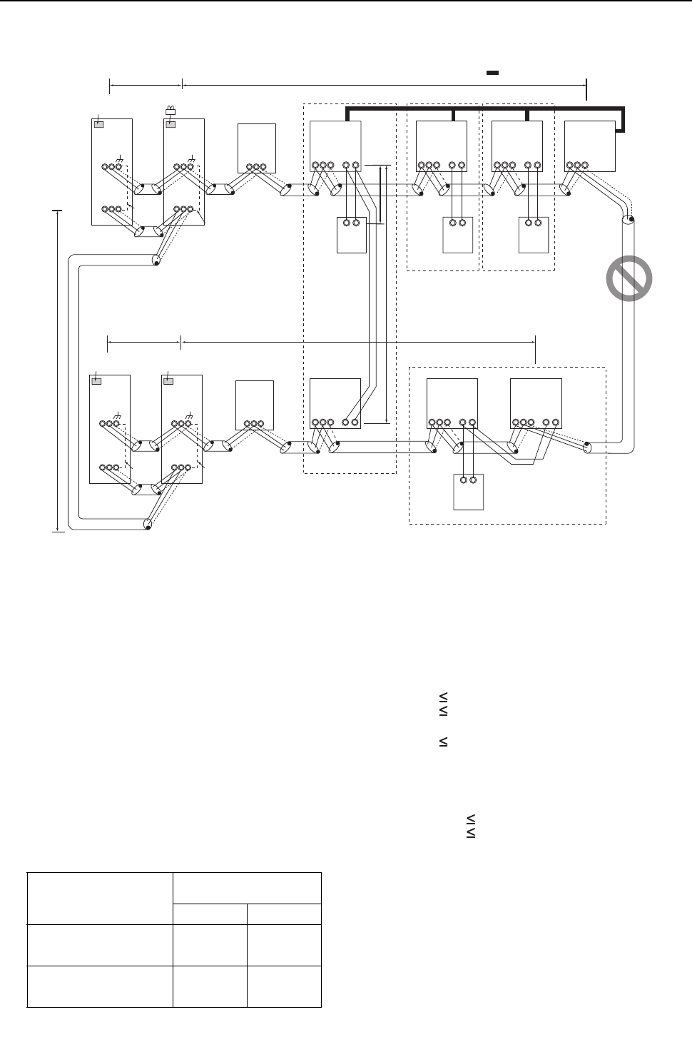
[ II Restrictions ]
41- 41 -
HWE09080 GB
8. Group operation of units in a system with multiple heat source units <PQRY>
(1) Sample control wiring
(2) Cautions
1) ME remote controller and MA remote controller cannot
both be connected to the same group of indoor units.
2) No more than 2 MA remote controllers can be connected
to a group of indoor units.
3) Do not connect the terminal blocks (TB5) on the indoor
units that are connected to different heat source units
with each other.
4) Replacement of male power jumper connector (CN41)
must be performed only on one of the heat source units.
5) Provide grounding to S terminal on the terminal block for
transmission line for centralized control (TB7) on only
one of the heat source units.
6) When the number of the connected indoor units is as
shown in the table below, one or more transmission
boosters (sold separately) are required.
To connect two transmission boosters, connect them in
parallel. (Observe the maximum number of connectable
indoor units that are listed in the specifications for each
heat source unit.)
The left table shows the number of transmission boost-
ers that is required by the system with three BC control-
lers. For each BC controller that is subtracted from the
above-mentioned system, two additional indoor units
can be connected.
(3) Maximum allowable length
1) Indoor-heat source transmission line
Maximum distance (1.25mm2 [AWG16] or larger)
L11+L12 200m [656ft]
L21+L22 200m [656ft]
2) Transmission line for centralized control
L31+L21 200m [656ft]
3) MA remote controller wiring
Same as [5] 6.
4) Maximum line distance via heat source unit
(1.25mm2 [AWG16] or larger)
L12+L31+L22 500m [1640ft]
L11+L31+L21 500m [1640ft]
IC
TB5
S
TB
15
12
01
IC
TB5
S
TB
15
12
03
A1 B2
MA
A1 B2
MA
LC
TB5
S
07
IC
TB5
S12
TB
15
IC
TB5
S
TB
15
12 12
0402
IC
TB5 TB15
S
05
A1 B2
MA
Group
IC
TB5
S
TB
15
12
06
A1 B2
MA
GroupGroup
Group
To be left
unconnected
m2
m3
Interlock operation with
the ventilation unit
L12
L22
L11
L21
OC
Move the male connector
from CN41 to CN40.
SW2-1 OFF
Leave the male
connector on
CN41 as it is.
SW2-1 OFF
Leave the male
connector on
CN41 as it is.
SW2-1 OFF
Leave the male
connector on
CN41 as it is.
SW2-1 OFF
TB3
TB7
S
51
OS
TB3
TB7
M1 M2
M1 M2
M1 M2
M1 M2
M1 M2
M1 M2 M1 M2 M1 M2 M1 M2
M1 M2
M1 M2
M1 M2
M1 M2M1 M2
M1 M2
M1 M2 M1 M2
S
52
OC
TB3
TB7
S
55
OS
TB3
TB7
S
56
L31
To be left
unconnected
S
S
BC
TB02
53
BC
TB02
57
To be left
unconnected
To be connected
Number of transmission boost-
er (sold separately) required
1 unit 2 units
When the P72 and P96 mod-
els are not included in the con-
nected indoor units
27 - 50 units -
When the P72 or P96 model is
included in the connected in-
door units
21 - 39 units 40 - 50 units
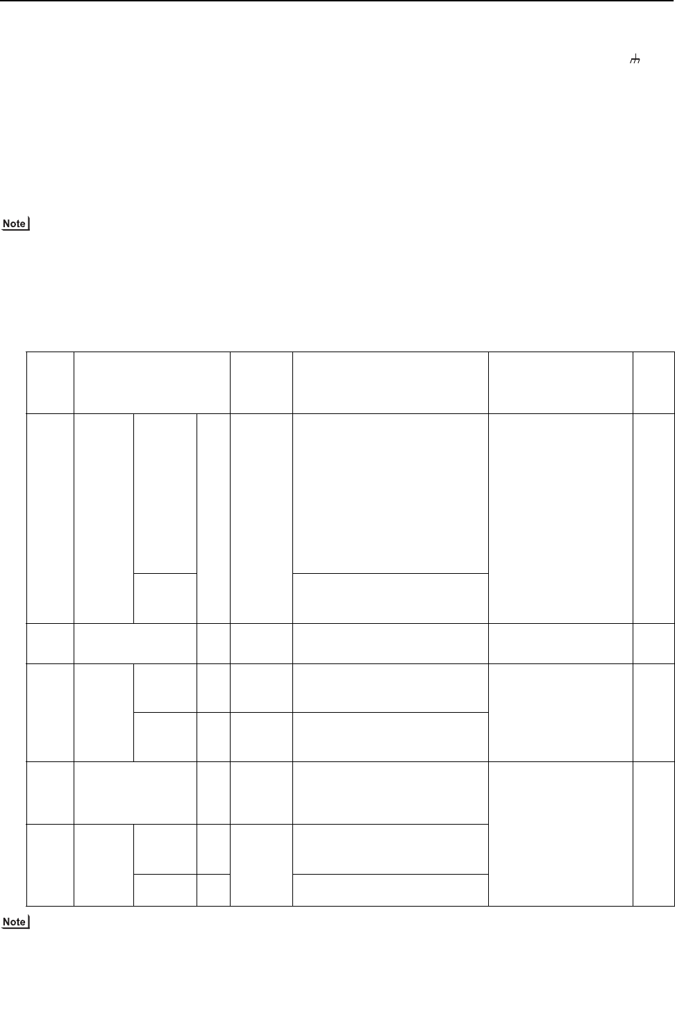
- 42 -
[ II Restrictions ]
GBHWE09080
(4) Wiring method
1) Indoor-heat source transmission line
Same as [5] 7.
Shielded cable connection
Same as [5] 7.
2) Transmission line for centralized control
Daisy-chain terminals M1 and M2 on the terminal block
for transmission line for centralized control (TB7) on the
heat source units (OC) in different refrigerant circuits and
on the OC and OS in the same refrigerant circuit
If a power supply unit is not connected to the transmis-
sion line for centralized control, replace the power jump-
er connector on the control board from CN41 to CN40 on
only one of the heat source units.
The heat source units in the same refrigerant circuit are
automatically designated as OC and OS in the order of
capacity from large to small (if two or more units have the
same capacity, in the order of address from small to
large).
Only use shielded cables.
Shielded cable connection
Daisy-chain the S terminal on the terminal block (TB7) on
the heat source units (OC, OS) with the shield wire of the
shielded cable. Short-circuit the earth terminal ( ) and
the S terminal on the terminal block (TB7) on the heat
source unit whose power jumper connector is mated with
CN40.
3) MA remote controller wiring
Same as [5] 6.
When 2 remote controllers are connected to the sys-
tem
Same as [5] 6.
Group operation of indoor units
Same as [5] 7.
4) LOSSNAY connection
Same as [5] 7.
5) Switch setting
Address setting is required as follows.
(5) Address setting method
The heat source units in the same refrigerant circuit are automatically designated as OC and OS.
They are designated as OC and OS in the descending order of capacity (ascending order of address if the capacities are the
same).
Proce-
dures Unit or controller
Address
setting
range
Setting method Notes
Fac-
tory
set-
ting
1 Indoor
unit
Main unit IC 01 to 50 Assign the smallest address to the main
unit in the group.
In a system with a sub BC controller,
make the settings for the indoor units in
the following order.
(i) Indoor unit to be connected to the main
BC controller
(ii) Indoor unit to be connected to sub BC
controller 1
(iii) Indoor unit to be connected to sub BC
controller 2
Make the settings for the indoor units in
the way that the formula "(i) < (ii) < (iii)"
is true.
Port number setting is
required
To perform a group op-
eration of indoor units
that feature different
functions, designate
the indoor unit in the
group with the greatest
number of functions as
the main unit.
00
Sub unit Assign sequential numbers starting with
the address of the main unit in the same
group +1. (Main unit address +1, main unit
address +2, main unit address +3, etc.)
2 LOSSNAY LC 01 to 50 Assign an arbitrary but unique address to
each of these units after assigning an ad-
dress to all indoor units.
None of these addresses may
overlap any of the indoor unit
addresses.
00
3MA
remote
controller
Main
remote
controller
MA No set-
tings re-
quired.
-Main
Sub
remote
controller
MA Sub
remote
controller
Settings to be made with the Sub/
Main switch
4 Heat source unit OC
OS
51 to 100 Assign sequential address to the heat
source units in the same refrigerant cir-
cuit.
The heat source units are automatically
designated as OC and OS.(Note)
To set the address to 100,
set the rotary switches to 50.
If the addresses that is as-
signed to the main BC con-
troller overlaps any of the
addresses that are assigned
to the heat source units or to
the sub BC controller, use a
different, unused address
within the setting range.
The use of a sub BC control-
ler requires the connection
of a main BC controller.
00
5 Auxiliary
heat
source
unit
BCcon-
troller (Sub) BS 51 to 100 Assign an address that equals the sum of
the smallest address of the indoor units
that are connected to the sub BC controller
and 50.
BC control-
ler (Main) BC OC (or OS if it exists) +1
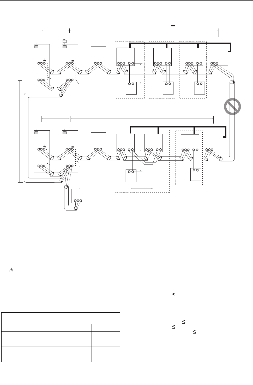
[ II Restrictions ]
43- 43 -
HWE09080 GB
9. A system in which a system controller is connected to the transmission line for centralized control and which is pow-
ered from a heat source unit <PQRY>
(1) Sample control wiring
(2) Cautions
1) ME remote controller and MA remote controller cannot both be con-
nected to the same group of indoor units.
2) No more than 2 MA remote controllers can be connected to a group
of indoor units.
3) Do not connect the terminal blocks (TB5) on the indoor units that are
connected to different heat source units with each other.
4) Replacement of male power jumper connector (CN41) must be per-
formed only on one of the heat source units.
5) Short-circuit the shield terminal (S terminal) and the earth terminal (
) on the terminal block for transmission line for centralized control
(TB7) on the heat source unit whose power jumper connector is mat-
ed with CN40.
6) When the number of the connected indoor units is as shown in the
table below, one or more transmission boosters (sold separately)
are required.
To connect two transmission boosters, connect them in parallel.
(Observe the maximum number of connectable indoor units that are
listed in the specifications for each heat source unit.)
The left table shows the number of transmission boosters
that is required by the system with three BC controllers. For
each BC controller that is subtracted from the above-men-
tioned system, two additional indoor units can be connected.
7) When a power supply unit is connected to the transmission
line for centralized control, leave the power jumper connec-
tor on CN41 as it is (factory setting).
(3) Maximum allowable length
1) Indoor-heat source transmission line
Same as [5] 8.
2) Transmission line for centralized control
Maximum line distance via heat source unit (1.25 mm2
[AWG16] min.)
L31+L32(L21) 200m [656ft]
3) MA remote controller wiring
Same as [5] 6.
4) Maximum line distance via heat source unit
(1.25mm2 [AWG16] or larger)
L32+L31+L12(L11) 500m [1640ft]
L32+L22(L21) 500m [1640ft]
L12(L11)+L31+L22(L21) 500m[1640ft]
IC
TB5
S
TB
15
12
01
IC
TB5
S
TB
15
12
02
A
1
B
2
MA
A
1
B
2
MA
LC
TB5
S
07
IC
TB5
S12
TB
15
IC
TB5
S
TB
15
12
0504
LC
TB5
S
08
IC
TB5
S
TB
15
12
03
A
1
B
2
MA
IC
TB5
S
TB
15
12
06
A
1
B
2
MA
A
1
B
2
MA
m3
L31
System controller
ABS
Note1
L32
OC
To be connected
m2 m1
Note1 When only the LM adapter is connected,
leave SW2-1 to OFF (as it is).
Note2 LM adapters require the power supply
capacity of single-phase AC 208 - 230V.
TB3
TB7
S
51
OS
TB3
TB7
M1 M2 M1 M2
M1 M2
M1 M2
M1 M2 M1 M2 M1 M2 M1 M2 M1 M2
M1 M2M1 M2M1 M2
M1 M2
M1 M2
M1 M2M1 M2
M1 M2 M1 M2
S
52
OC
TB3
TB7
S
55
OS
TB3
TB7
S
56
Group
Group Group
Group Group
Interlock operation with
the ventilation unit
Move the male connector
from CN41 to CN40.
SW2-1 OFF
Leave the male
connector on
CN41 as it is.
SW2-1 OFF
Leave the male
connector on
CN41 as it is.
SW2-1 OFF
Leave the male
connector on
CN41 as it is.
SW2-1 OFF
To be left
unconnected
To be left
unconnected
To be left
unconnected
S
BC
TB02
53
S
BC
TB02
57
L22
L21
L12
L11
Number of transmission booster
(sold separately) required
1 unit 2 units
When the P72 and P96 models are
not included in the connected in-
door units
27 - 50 units -
When the P72 or P96 model is in-
cluded in the connected indoor
units
21 - 39 units 40 - 50 units
- 44 -
[ II Restrictions ]
GBHWE09080
(4) Wiring method
1) Indoor-heat source transmission line
Same as [5] 7.
Only use shielded cables.
Shielded cable connection
Same as [5] 7.
2) Transmission line for centralized control
Daisy-chain terminals A and B on the system controller, ter-
minals M1 and M2 on the terminal block for transmission line
for centralized control (TB7) on the heat source units (OC)
in different refrigerant circuits and on the heat source units
(OC and OS) in the same refrigerant circuit.
If a power supply unit is not connected to the transmission
line for centralized control, replace the power jumper con-
nector on the control board from CN41 to CN40 on only one
of the heat source units.
If a system controller is connected, set the central control
switch (SW2-1) on the control board of all heat source units
to "ON."
The heat source units in the same refrigerant circuit are
automatically designated as OC, OS1, and OS2 in the
order of capacity from large to small (if two or more units
have the same capacity, in the order of address from
small to large).
Only use shielded cables.
Shielded cable connection
Daisy-chain the S terminal of the terminal block (TB7) on
the system controller, OC, and OS with the shield of the
shielded cable. Short-circuit the earth terminal ( ) and
the S terminal on the terminal block (TB7) on the heat
source unit whose power jumper connector is mated with
CN40.
3) MA remote controller wiring
Same as [5] 6.
When 2 remote controllers are connected to the sys-
tem
Same as [5] 6.
Group operation of indoor units
Same as [5] 6.
4) LOSSNAY connection
Connect terminals M1 and M2 on the terminal block
(TB5) on the indoor unit (IC) to the appropriate terminals
on the terminal block for indoor-heat source transmission
line (TB5) on LOSSNAY (LC). (Non-polarized two-wire)
Indoor units must be interlocked with the LOSSNAY unit
using the system controller. (Refer to the operation man-
ual for the system controller for the setting method.) In-
terlock setting from the remote controller is required if the
ON/OFF remote controller alone or the LM adapter alone
is connected.
5) Switch setting
Address setting is required as follows.
(5) Address setting method
The heat source units in the same refrigerant circuit are automatically designated as OC and OS.
They are designated as OC and OS in the descending order of capacity (ascending order of address if the capacities are the
same).
Proce-
dures Unit or controller
Ad-
dress
setting
range
Setting method Notes
Fac-
tory
set-
ting
1 Indoor
unit
Main unit IC 01 to
50
Assign the smallest address to the main unit
in the group.
In a system with a sub BC controller, make
the settings for the indoor units in the fol-
lowing order.
(i) Indoor unit to be connected to the main BC
controller
(ii) Indoor unit to be connected to sub BC
controller 1
(iii) Indoor unit to be connected to sub BC
controller 2
Make the settings for the indoor units in the
way that the formula "(i) < (ii) < (iii)" is true.
Port number setting is
required
To perform a group op-
eration of indoor units
that feature different
functions, designate
the indoor unit in the
group with the greatest
number of functions as
the main unit.
00
Sub unit Assign sequential numbers starting with the
address of the main unit in the same group
+1. (Main unit address +1, main unit address
+2, main unit address +3, etc.)
2 LOSSNAY LC 01 to
50
Assign an arbitrary but unique address to
each of these units after assigning an address
to all indoor units.
None of these addresses may
overlap any of the indoor unit
addresses.
00
3MA
remote
controller
Main
remote con-
troller
MA No set-
tings re-
quired.
-Make the same indoor unit
group settings with the system
controller as the ones that
were made with the MA remote
controller.
Main
Sub
remote con-
troller
MA Sub
remote
controller
Settings to be made with the Sub/
Main switch
4 Heat source unit
(Note)
OC
OS
51 to 100 Assign sequential address to the heat
source units in the same refrigerant circuit.
The heat source units are automatically
designated as OC and OS.(Note)
To set the address to 100,
set the rotary switches to 50.
If the addresses that is as-
signed to the main BC con-
troller overlaps any of the
addresses that are assigned
to the heat source units or to
the sub BC controller, use a
different, unused address
within the setting range.
The use of a sub BC control-
ler requires the connection
of a main BC controller.
00
5 Auxiliary
heat
source
unit
BCcon-
troller (Sub) BS 51 to 100 Assign an address that equals the sum of the
smallest address of the indoor units that are
connected to the sub BC controller and 50.
BC control-
ler (Main) BC OC (or OS if it exists) +1
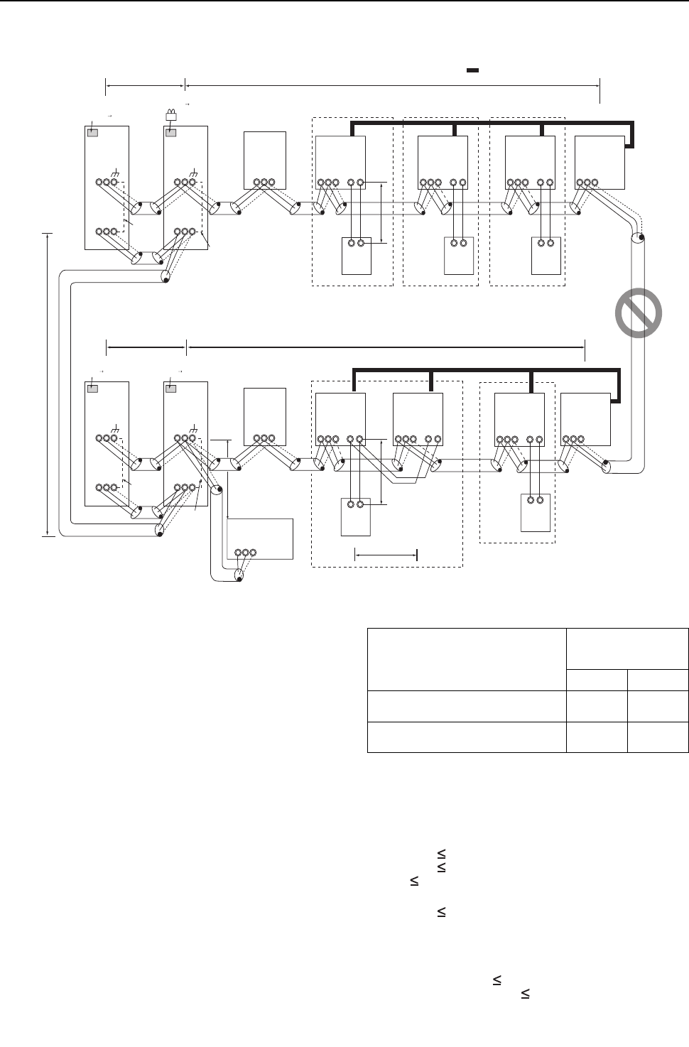
[ II Restrictions ]
45- 45 -
HWE09080 GB
10. An example of a system in which a system controller is connected to the indoor-heat source transmission line (ex-
cept LM adapter) <PQRY>
(1) Sample control wiring
(2) Cautions
1) ME remote controller and MA remote controller cannot both be con-
nected to the same group of indoor units.
2) No more than 2 MA remote controllers can be connected to a group
of indoor units.
3) Do not connect the terminal blocks (TB5) on the indoor units that are
connected to different heat source units with each other.
4) Replacement of male power jumper connector (CN41) must be per-
formed only on one of the heat source units.
5) Provide grounding to S terminal on the terminal block for transmis-
sion line for centralized control (TB7) on only one of the heat source
units.
6) A maximum of 3 system controllers can be connected to the indoor-
heat source transmission line, with the exception that only one G(B)-
50A may be connected.
7) When the total number of indoor units exceeds 20 (12 if one or more
indoor units of the 72 model or above is connected), it may not be
possible to connect a system controller to the indoor-heat source
transmission line.
8) When the number of the connected indoor units is as shown in the
table below, one or more transmission boosters (sold separately)
are required.
To connect two transmission boosters, connect them in parallel.
(Observe the maximum number of connectable indoor units that are
listed in the specifications for each heat source unit.)
The table above shows the number of transmission boosters that is
required by the system with three BC controllers. For each BC con-
troller that is subtracted from the above-mentioned system, two ad-
ditional indoor units can be connected.
(3) Maximum allowable length
1) Indoor-heat source transmission line
Maximum distance (1.25mm2 [AWG16] or larger)
L11+L12 200m [656ft]
L21+L22 200m [656ft]
L25 200m [656ft]
2) Transmission line for centralized control
L31+L21 200m [656ft]
3) MA remote controller wiring
Same as [5] 6.
4) Maximum line distance via heat source unit
(1.25mm2 [AWG16] or larger)
L25+L31+L12(L11) 500m [1640ft]
L12(L11)+L31+L22(L21) 500m [1640ft]
IC
TB5
S
TB
15
12
01
IC
TB5
S
TB
15
12
02
A
1
B
2
MA
A
1
B
2
MA
LC
TB5
S
07
IC
TB5
S12
TB
15
IC
TB5
S
TB
15
12
0504
LC
TB5
S
08
IC
TB5
S
TB
15
12
03
A
1
B
2
MA
IC
TB5
S
TB
15
12
06
A
1
B
2
MA
A
1
B
2
MA
GroupGroupGroup
Group Group
m3
Interlock operation with
the ventilation unit
OC
To be connected
m2 m1
Note1 LM adapters cannot be connected to the
indoor-heat source transmission line.
TB3
TB7
S
51
OS
TB3
TB7
S
52
OC
TB3
TB7
S
55
OS
TB3
TB7
S
56
L31
ABS
L25
M2M1 M2M1
M2M1 M2M1
M2M1 M2M1 M2M1 M2M1 M2M1
M2M1
M2M1
M2M1M2M1
M2M1
M2M1
M2M1
M2M1
M2M1
To be left
unconnected
SW2-1 OFF ON
SW2-1 OFF ON
Leave the male
connector on
CN41 as it is.
Move the male connector .
from CN41 to CN40.
SW2-1 OFF ON
Leave the male
connector on
CN41 as it is.
SW2-1 OFF ON
Leave the male
connector on
CN41 as it is.
System controller
Note1
To be left
unconnected
To be left
unconnected
S
BC
TB02
53
S
BC
TB02
57
L22
L21
L12
L11
Number of transmission
booster (sold separately)
required
1 unit 2 units
When the P72 and P96 models are not in-
cluded in the connected indoor units
27 - 50
units -
When the P72 or P96 model is included in
the connected indoor units
21 - 39
units
40 - 50
units
- 46 -
[ II Restrictions ]
GBHWE09080
(4) Wiring method
1) Indoor-heat source transmission line
Daisy-chain terminals M1 and M2 of the terminal block for indoor-
heat source transmission line (TB3) on the heat source units (OC
and OS), of the terminal block for indoor-heat source transmission
line (TB02) on the main and sub BC controllers (BC and BS), of the
terminal block for indoor-heat source transmission line (TB5) on
each indoor unit (IC), and the S terminal of the system control-
ler.(Non-polarized two-wire)
Only use shielded cables.
The heat source units in the same refrigerant circuit are automatical-
ly designated as OC and OS in the order of capacity from large to
small (if two or more units have the same capacity, in the order of
address from small to large).
Shielded cable connection
Daisy-chain the ground terminal ( ) on the heat source units (OC
and OS), the S terminal of the terminal block (TB02) on the BC and
BS, and the S terminal of the terminal block (TB5) on the indoor unit
(IC) with the shield of the shielded cable.
2) Transmission line for centralized control
Daisy-chain terminals M1 and M2 on the terminal block for transmis-
sion line for centralized control (TB7) on the heat source units (OC)
in different refrigerant circuits and on the OC and OS in the same re-
frigerant circuit.
If a power supply unit is not connected to the transmission line for
centralized control, replace the power jumper connector on the con-
trol board from CN41 to CN40 on only one of the heat source units.
Set the central control switch (SW2-1) on the control board of all
heat source units to "ON."
Only use shielded cables.
Shielded cable connection
Daisy-chain the S terminal on the terminal block (TB7) on the heat
source units (OC, OS) with the shield wire of the shielded cable.
Short-circuit the earth terminal ( ) and the S terminal on the ter-
minal block (TB7) on the heat source unit whose power jumper con-
nector is mated with CN40.
3) MA remote controller wiring
Same as [5] 6.
When 2 remote controllers are connected to the sys-
tem
Same as [5] 6.
Group operation of indoor units
Same as [5] 6.
4) LOSSNAY connection
Connect terminals M1 and M2 on the terminal block (TB5) on the in-
door units (IC) to the appropriate terminals on the terminal block for
indoor-heat source transmission line (TB5) on LOSSNAY (LC).
(Non-polarized two-wire)
Indoor units must be interlocked with the LOSSNAY unit using the
system controller. (Refer to the operation manual for the system
controller for the setting method.) Interlock setting from the remote
controller is required if the ON/OFF remote controller alone is con-
nected.
5) Switch setting
Address setting is required as follows.
(5) Address setting method
The heat source units in the same refrigerant circuit are automatically designated as OC and OS.
They are designated as OC and OS in the descending order of capacity (ascending order of address if the capacities are the
same).
Proce-
dures Unit or controller
Ad-
dress
setting
range
Setting method Notes
Fac-
tory
set-
ting
1 Indoor
unit
Main unit IC 01 to
50
Assign the smallest address to the main unit
in the group.
In a system with a sub BC controller, make
the settings for the indoor units in the fol-
lowing order.
(i) Indoor unit to be connected to the main BC
controller
(ii) Indoor unit to be connected to sub BC
controller 1
(iii) Indoor unit to be connected to sub BC
controller 2
Make the settings for the indoor units in the
way that the formula "(i) < (ii) < (iii)" is true.
Port number setting is
required
To perform a group op-
eration of indoor units
that feature different
functions, designate
the indoor unit in the
group with the greatest
number of functions as
the main unit.
00
Sub unit Assign sequential numbers starting with the
address of the main unit in the same group
+1. (Main unit address +1, main unit address
+2, main unit address +3, etc.)
2 LOSSNAY LC 01 to
50
Assign an arbitrary but unique address to
each of these units after assigning an address
to all indoor units.
None of these addresses may
overlap any of the indoor unit
addresses.
00
3MA
remote
controller
Main
remote con-
troller
MA No set-
tings re-
quired.
-Make the same indoor unit
group settings with the system
controller as the ones that
were made with the MA remote
controller.
Main
Sub
remote con-
troller
MA Sub
remote
controller
Settings to be made with the Sub/
Main switch
4 Heat source unit OC
OS
51 to 100 Assign sequential address to the heat
source units in the same refrigerant circuit.
The heat source units are automatically
designated as OC and OS.(Note)
To set the address to 100,
set the rotary switches to 50.
If the addresses that is as-
signed to the main BC con-
troller overlaps any of the
addresses that are assigned
to the heat source units or to
the sub BC controller, use a
different, unused address
within the setting range.
The use of a sub BC control-
ler requires the connection
of a main BC controller.
00
5 Auxiliary
heat
source
unit
BCcon-
troller (Sub) BS 51 to 100 Assign an address that equals the sum of the
smallest address of the indoor units that are
connected to the sub BC controller and 50.
BC control-
ler (Main) BC OC (or OS if it exists) +1
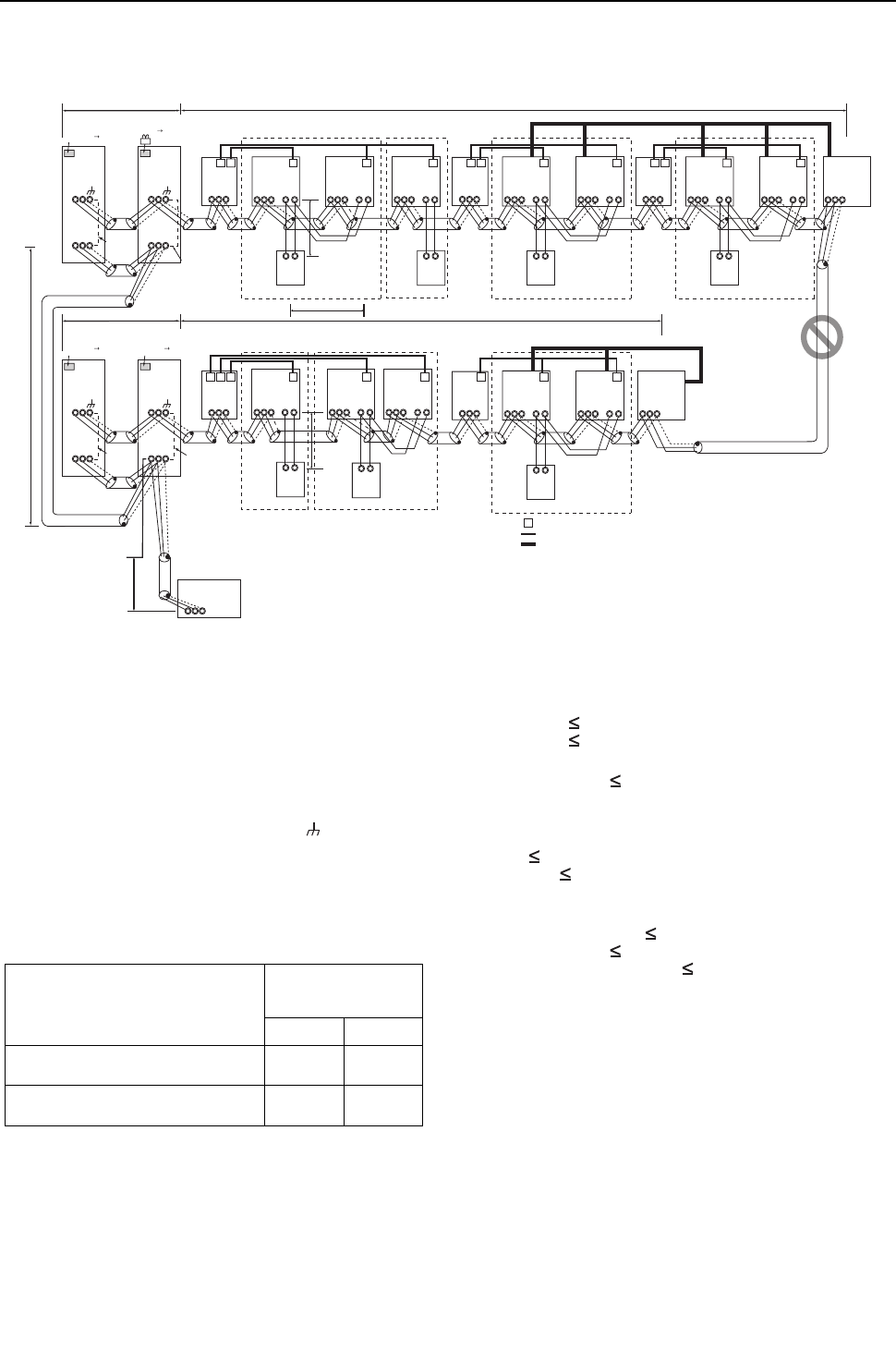
[ II Restrictions ]
47- 47 -
HWE09080 GB
11. A system with multiple BC controller connections (with a system controller connected to the centralized control line)
<PQRY>
(1) Sample control wiring
(2) Cautions
1) ME remote controller and MA remote controller cannot both be con-
nected to the same group of indoor units.
2) No more than 2 MA remote controllers can be connected to a group
of indoor units.
3) Do not connect the terminal blocks (TB5) on the indoor units that are
connected to different heat source units with each other.
4) Replacement of male power jumper connector (CN41) must be per-
formed only on one of the heat source units.
5) Short-circuit the S (shield) terminal of the terminal block for the cen-
tral control unit (TB7) and the ground terminal ( ) on the heat
source unit whose power jumper was moved from CN41 to CN40.
6) When the number of the connected indoor units is as shown in the
table below, one or more transmission boosters (sold separately)
are required.
To connect two transmission boosters, connect them in parallel.
(Observe the maximum number of connectable indoor units that are
listed in the specifications for each heat source unit.)
The table above shows the number of transmission boost-
ers that is required by the system with three BC controllers.
For each BC controller that is subtracted from the above-
mentioned system, two additional indoor units can be con-
nected.
7) When a power supply unit is connected to the transmission
line for centralized control, leave the power jumper connec-
tor on CN41 as it is (factory setting).
(3) Maximum allowable length
1) Indoor-heat source transmission line
Maximum distance (1.25mm2 [AWG16] or larger)
L11+L12 200m [656ft]
L21+L22 200m [656ft]
2) Transmission line for centralized control
L31+L32(L21) 200m [656ft]
3) MA remote controller wiring
Maximum overall line length
(0.3 to 1.25mm2 [AWG22 to 16])
m1 200m [656ft]
m2+m3 200m [656ft]
4) Maximum line distance via heat source unit
(1.25mm2 [AWG16] or larger)
L32+L31+L12(L11) 500m [1640ft]
L32+L22(L21) 500m [1640ft]
L12(L11)+L31+L22(L21) 500m[1640ft]
L11
L21
OC
TB3
TB7
S
51
L31
ABS
L32
OS1
TB3
TB7
M1M2
S
52
OC
TB3
TB7
S
54
OS1
TB3
TB7
S
55
SW2-1 OFF ON
Move the male connector
from CN41 to CN40
Group
Group Group Group
Group Group Group
To be left
unconnected
To be left
unconnected
To be left
unconnected
To be connected
M1M2
M1M2 M1M2
M1M2
M1M2
M1M2 M1M2
M1M2
*1 When only the LM adapter is connected, leave SW2-1 to OFF (as it is).
*2 LM adapters require the power supply capacity of single-phase AC 208 - 230V.
IC
TB5
S
TB
15
12
01
IC
TB5
S
TB
15
12
02
IC
TB5
S
TB
15
12
04
IC
TB5
S
TB
15
12
06
A1 B2
MA
A1 B2
MA
A1 B2
MA
IC
TB5
S12
TB
15
IC
TB5
S
TB
15
12
0503
L12
L22
IC
TB5
S
TB
15
12
07
IC
TB5
S
TB
15
12
08
A1 B2
MA
IC
TB5
S
TB
15
12
09
IC
TB5
S
TB
15
12
10
A1 B2
MA
A1 B2
MA
BC
BC
TB02
S
53 57
TB02
M1M2
S
BS
TB02
S
BS
TB02
S
1 1 2 1 222 12
57
1 1 2 1 1
LC
TB5
S
14
323 1
Numbers in the square indicate port numbers.
Connection to BC controllers
56 59
Interlock operation with the ventilation unit
IC
TB5
S
TB
15
12
11
IC
TB5
S
TB
15
12
12
A1 B2
MA
61
BS
TB02
S
1 2
LC
TB5
S
13
12
m2
m3
m1
SW2-1 OFF ON
Leave the male
connector on
CN41 as it is.
SW2-1 OFF ON
Leave the male
connector on
CN41 as it is.
SW2-1 OFF ON
Leave the male
connector on
CN41 as it is.
System
controller
Note1
M1M2 M1M2 M1M2 M1M2 M1M2 M1M2 M1M2 M1M2 M1M2 M1M2
M1M2 M1M2 M1M2 M1M2 M1M2 M1M2
M1M2
Number of transmission
booster (sold separately)
required
1 unit 2 units
When the P72 and P96 models are not in-
cluded in the connected indoor units
27 - 50
units -
When the P72 or P96 model is included in
the connected indoor units
21 - 39
units
40 - 50
units
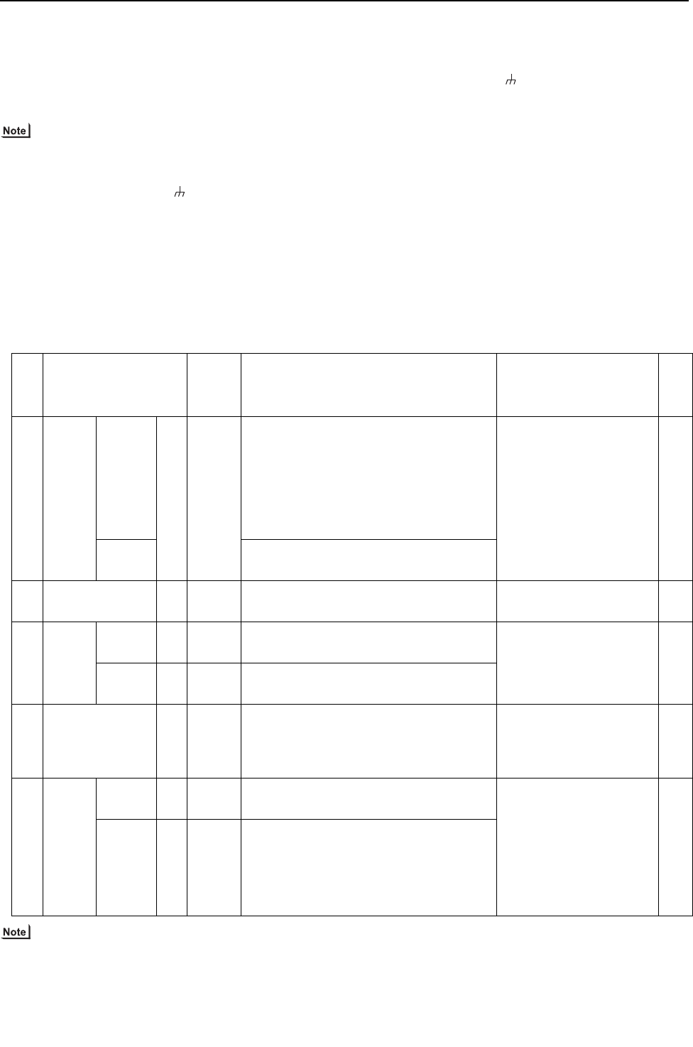
- 48 -
[ II Restrictions ]
GBHWE09080
(4) Wiring method
1) Indoor-heat source transmission line
Daisy-chain terminals M1 and M2 of the terminal block for indoor-
heat source transmission line (TB3) on the heat source units (OC
and OS), of the terminal block for indoor-heat source transmission
line (TB02) on the main and sub BC controllers (BC and BS), and of
the terminal block for indoor-heat source transmission line (TB5) on
each indoor unit (IC). (Non-polarized two-wire)
Shielded cable connection
The heat source units in the same refrigerant circuit are auto-
matically designated as OC, OS1, and OS2 in the order of ca-
pacity from large to small (if two or more units have the same
capacity, in the order of address from small to large).
Daisy-chain the ground terminal ( ) on the heat source units (OC
and OS), the S terminal of the terminal block (TB02) on the BC and
BS, and the S terminal of the terminal block (TB5) on the indoor unit
(IC) with the shield of the shielded cable.
Only use shielded cables.
2) Transmission line for centralized control
Daisy-chain terminals A and B on the terminal block for transmission
line for centralized control (TB7) on the heat source units (OC) in dif-
ferent refrigerant circuits and on the OC and OS (Note) in the same
refrigerant circuit.
If a power supply unit is not connected to the transmission line for
centralized control, replace the power jumper connector on the con-
trol board from CN41 to CN40 on only one of the heat source units.
Set the central control switch (SW2-1) on the control board of all
heat source units to "ON."
Only use shielded cables.
Shielded cable connection
Daisy-chain the S terminal of the terminal block (TB7) on the system
controller, OC, and OS with the shield of the shielded cable. Short-
circuit the earth terminal ( ) and the S terminal on the terminal
block (TB7) on the heat source unit whose power jumper connector
is mated with CN40.
3) MA remote controller wiring
Same as [5] 6.
When 2 remote controllers are connected to the system
Same as [5] 6.
Group operation of indoor units
Same as [5] 6.
4) LOSSNAY connection
Connect terminals M1 and M2 on the terminal block (TB5) on the in-
door unit (IC) to the appropriate terminals on the terminal block for
indoor-heat source transmission line (TB5) on LOSSNAY (LC).
(Non-polarized two-wire)
Indoor units must be interlocked with the LOSSNAY unit us-
ing the system controller. (Refer to the operation manual for
the system controller for the setting method.) Interlock set-
ting from the remote controller is required if the ON/OFF re-
mote controller alone or the LM adapter alone is connected.
5) Switch setting
Address setting is required as follows.
(5) Address setting method
The heat source units in the same refrigerant circuit are automatically designated as OC and OS.
They are designated as OC and OS in the descending order of capacity (ascending order of address if the capacities are the same).
Pro
ce-
du-
res
Unit or controller
Ad-
dress
setting
range
Setting method Notes
Fact
ory
set-
ting
1 Indoor
unit
Main unit IC 01 to 50 Assign the smallest address to the main unit in the
group.
In a system with a sub BC controller, make the set-
tings for the indoor units in the following order.
(i) Indoor unit to be connected to the main BC control-
ler
(ii) Indoor unit to be connected to sub BC controller 1
(iii) Indoor unit to be connected to sub BC controller 2
Make the settings for the indoor units in the way that
the formula "(i) < (ii) < (iii)" is true.
Port number setting is re-
quired
To perform a group opera-
tion of indoor units that
feature different functions,
designate the indoor unit
in the group with the
greatest number of func-
tions as the main unit.
00
Sub unit Assign sequential numbers starting with the address of
the main unit in the same group +1. (Main unit address
+1, main unit address +2, main unit address +3, etc.)
2 LOSSNAY LC 01 to 50 Assign an arbitrary but unique address to each of these
units after assigning an address to all indoor units.
None of these addresses may
overlap any of the indoor unit ad-
dresses.
00
3MA
remote
control-
ler
Main re-
mote
controller
MA No set-
tings re-
quired.
-Make the same indoor unit group
settings with the system controller
as the ones that were made with
the MA remote controller.
Mai
n
Sub re-
mote con-
troller
MA Sub re-
mote
controller
Settings to be made with the Sub/Main switch
4 Heat source unit OC
OS
51 to 100 The sum of the smallest address of the indoor units in
the same system and 50.
Assign sequential address to the heat source units in
the same refrigerant circuit.
The heat source units are automatically designated
as OC and OS.(Note)
To set the address to 100, set
the rotary switches to 50. 00
5 Auxilia-
ry heat
source
unit
BC
controller
(Sub)
BS 51 to 100 Assign an address that equals the sum of the smallest
address of the indoor units that are connected to the
sub BC controller and 50.
To set the address to 100, set
the rotary switches to 50.
If the addresses that is assigned
to the main BC controller over-
laps any of the addresses that
are assigned to the heat source
units or to the sub BC control-
ler, use a different, unused ad-
dress within the setting range.
The use of a sub BC controller
requires the connection of a
main BC controller.
00
BC con-
troller
(Main)
BC 51 to
100
OC (or OS if it exists) +1
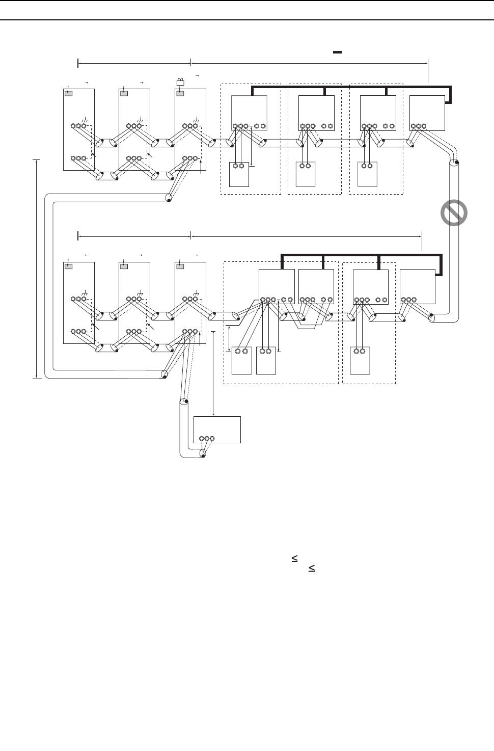
[ II Restrictions ]
49- 49 -
HWE09080 GB
[6] An Example of a System to which an ME Remote Controller is connected
1. A system in which a system controller is connected to the centralized control transmission line <PQHY>
(1) Sample control wiring
(2) Cautions
1) ME remote controller and MA remote controller cannot
both be connected to the same group of indoor units.
2) No more than 3 ME remote controllers can be connected
to a group of indoor units.
3) Do not connect the terminal blocks (TB5) on the indoor
units that are connected to different heat source units
with each other.
4) Replace the power jumper connector of the control board
from CN41 to CN40 on only one of the heat source units.
5) Provide an electrical path to ground for the S terminal on
the terminal block for centralized control on only one of
the heat source units.
6) A transmission booster must be connected to a system
in which the total number of connected indoor units ex-
ceeds 20.
7) A transmission booster is required in a system to which
more than 16 indoor including one or more indoor units
of the 72 model or above are connected.
8) When a power supply unit is connected to the transmis-
sion line for centralized control, leave the power jumper
connector on CN41 as it is (factory setting).
(3) Maximum allowable length
1) Indoor-heat source transmission line
Same as [5] 3.
2) Transmission line for centralized control
Same as [5] 4.
3) ME remote controller wiring
Maximum overall line length
(0.3 to 1.25mm2 [AWG22 to 16])
m1 10m [32ft]
m2+m3 10m [32ft]
If the standard-supplied cable must be extended, use a
cable with a diameter of 1.25mm2 [AWG16]. The section
of the cable that exceeds 10m [32ft] must be included in
the maximum indoor-heat source transmission line dis-
tance described in 1).
When connected to the terminal block on the Simple re-
mote controller, use cables that meet the following cable
size specifications: 0.75 - 1.25 mm2 [AWG18-14].
4) Maximum line distance via heat source unit
(1.25mm2 or larger)
Same as [5] 4.
IC
TB5
S
TB
15
1 2
01
IC
TB5
S
TB
15
1 2
02
LC
TB5
S
07
IC
TB5
S 1 2
TB
15
IC
TB5
S
TB
15
1 2
05 04
LC
TB5
S
08
IC
TB5
S
TB
15
1 2
03
IC
TB5
S
TB
15
1 2
06
A B
RC
101
A B
RC
102
A B
RC
103
Group Group
Group Group Group
M1 M2 M1 M2 M1 M2 M1 M2
M1 M2 M1 M2 M1 M2 M1 M2
L12 L11
L22 L21
L31
A B S
L32
Note1
System controller
Interlock operation with
the ventilation unit
OC
TB3
TB7
S
51
m1
OS1
TB3
TB7
S
52
OS2
TB3
TB7
M1 M2 M1 M2 M1 M2
M1 M2 M1 M2 M1 M2
S
53
OC
TB3
TB7
S
54
OS1
TB3
TB7
S
55
OS2
TB3
TB7
M1 M2 M1 M2 M1 M2
M1 M2 M1 M2 M1 M2
S
56
Leave the male
connector on
CN41 as it is.
SW2-1 OFF ON
Leave the male
connector on
CN41 as it is.
SW2-1 OFF ON
Leave the male
connector on
CN41 as it is.
SW2-1 OFF ON
Leave the male
connector on
CN41 as it is.
SW2-1 OFF ON
Leave the male
connector on
CN41 as it is.
SW2-1 OFF ON
SW2-1 OFF ON
Move the male connector
from CN41 to CN40.
To be connected
To be left
unconnected
To be left
unconnected To be left
unconnected
To be left
unconnected
To be left
unconnected
104
A B
RC
154
A B
RC
m3
106
A B
RC
m2
Note1 When only the LM adapter is connected,
leave SW2-1 to OFF (as it is).
Note2 LM adapters require the power supply
capacity of single-phase AC 208/230V.

- 50 -
[ II Restrictions ]
GBHWE09080
(4) Wiring method
1) Indoor-heat source transmission line
Same as [5] 1.
Shielded cable connection
Same as [5] 1.
2) Transmission line for centralized control
Same as [5] 4.
Shielded cable connection
Same as [5] 4.
3) ME remote controller wiring
ME remote controller is connectable anywhere on the in-
door-heat source transmission line.
When 2 remote controllers are connected to the sys-
tem
Refer to the section on Switch Setting.
Performing a group operation (including the group
operation of units in different refrigerant circuits).
Refer to the section on Switch Setting.
4) LOSSNAY connection
Same as [5] 4.
5) Switch setting
Address setting is required as follows.
(5) Address setting method
The heat source units in the same refrigerant circuit are automatically designated as OC, OS1, and OS2.
Proce-
dures Unit or controller Address setting
range Setting method Notes Factory
setting
1 Indoor
unit
Main unit IC 01 to 50 Assign the smallest ad-
dress to the main unit in
the group.
To perform a group
operation of indoor
units that have differ-
ent functions, desig-
nate the indoor unit in
the group with the
greatest number of
functions as the main
unit.
00
Sub unit Assign sequential num-
bers starting with the ad-
dress of the main unit in
the same group +1.
(Main unit address +1,
main unit address +2,
main unit address +3,
etc.)
2 LOSSNAY LC 01 to 50 Assign an arbitrary but
unique address to each
of these units after as-
signing an address to all
indoor units.
None of these ad-
dresses may overlap
any of the indoor unit
addresses.
00
3ME re-
mote
controller
Main
remote
controller
RC 101 to 150 Add 100 to the main unit
address in the group
It is not necessary to
set the 100s digit.
To set the address
to 200, set the rota-
ry switches to 00.
101
Sub
remote
controller
RC 151 to 200 Add 150 to the main unit
address in the group
4 Heat source unit OC
OS1
OS2
51 to 100 Assign sequential ad-
dress to the heat source
units in the same refrig-
erant circuit. The heat
source units are auto-
matically designated as
OC, OS1, and OS2.
(Note)
To set the address to
100, set the rotary
switches to 50.
00
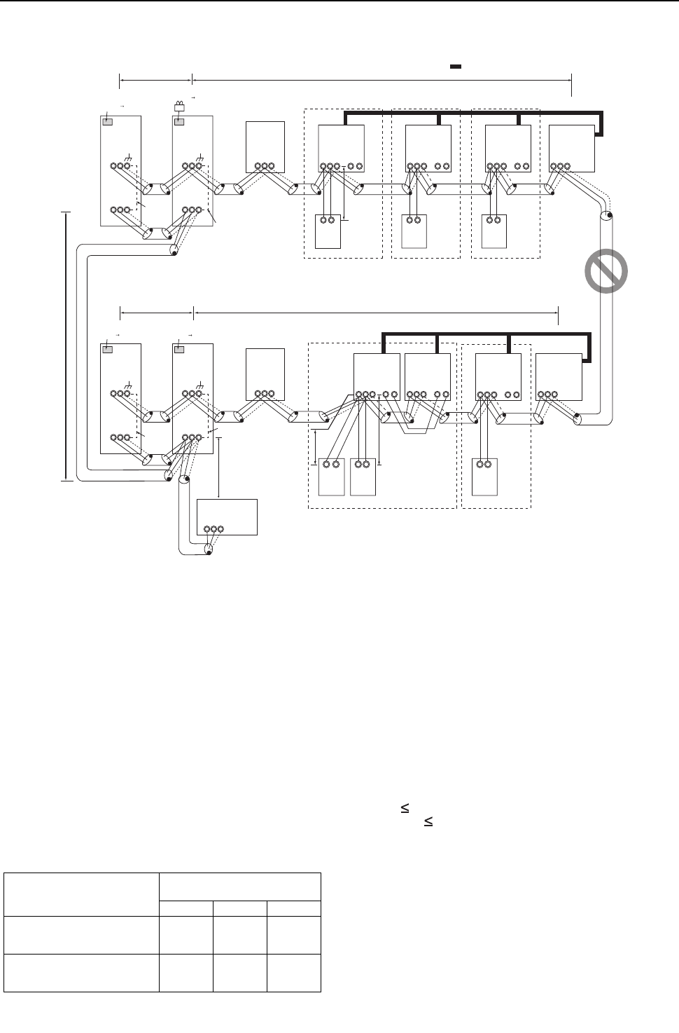
[ II Restrictions ]
51- 51 -
HWE09080 GB
2. A system in which a system controller is connected to the centralized control transmission line <PQRY>
(1) Sample control wiring
(2) Cautions
1) ME remote controller and MA remote controller cannot both
be connected to the same group of indoor units.
2) No more than 3 ME remote controllers can be connected to
a group of indoor units.
3) Do not connect the terminal blocks (TB5) on the indoor units
that are connected to different heat source units with each
other.
4) Replace the power jumper connector of the control board
from CN41 to CN40 on only one of the heat source units.
5) Provide an electrical path to ground for the S terminal on the
terminal block for centralized control on only one of the heat
source units.
6) When the number of the connected indoor units is as shown
in the table below, one or more transmission boosters (sold
separately) are required.
To connect two transmission boosters, connect them in par-
allel. (Observe the maximum number of connectable indoor
units that are listed in the specifications for each heat source
unit.)
The left table shows the number of transmission boosters
that is required by the system with three BC controllers. For
each BC controller that is subtracted from the above-men-
tioned system, two additional indoor units can be connected.
7) When a power supply unit is connected to the transmission
line for centralized control, leave the power jumper connec-
tor on CN41 as it is (factory setting).
(3) Maximum allowable length
1) Indoor-heat source transmission line
Same as [5] 8.
2) Transmission line for centralized control
Same as [5] 9.
3) ME remote controller wiring
Maximum overall line length
(0.3 to 1.25mm2 [AWG22 to 16])
m1 10m [32ft]
m2+m3 10m [32ft]
If the standard-supplied cable must be extended, use a
cable with a diameter of 1.25mm2 [AWG16]. The section
of the cable that exceeds 10m [32ft] must be included in
the maximum indoor-heat source transmission line dis-
tance described in (1).
When connected to the terminal block on the Simple re-
mote controller, use cables that meet the following cable
size specifications: 0.75 - 1.25 mm2 [AWG18-16].
4) Maximum line distance via heat source unit
(1.25 mm2 [AWG16] or large)
Same as [5] 9.
IC
TB5
S
TB
15
12
01
IC
TB5
S
TB
15
12
02
LC
TB5
S
07
IC
TB5
S12
TB
15
IC
TB5
S
TB
15
12
0504
LC
TB5
S
08
IC
TB5
S
TB
15
12
03
IC
TB5
S
TB
15
12
06
A1 B2
RC
101
A1 B2
RC
102
A1 B2
RC
103
Group
Group Group
Group Group
To be connected
M1M2 M1M2M1M2
M1M2 M1M2 M1M2 M1M2
L31
ABS
L32
OC
m1
TB3
TB7
M1 M2
S
51
OS
TB3
TB7
M1M2
M1M2 M1M2
S
52
OC
TB3
TB7
S
55
OS
TB3
TB7
S
56
To be left
unconnected
Interlock operation with the ventilation unit
*1 When only the LM adapter is connected, leave SW2-1 to OFF (as it is).
*2 LM adapters require the power supply capacity of single-phase AC 208 - 230V.
System controller
Note1
SW2-1 OFF ON
Leave the male
connector on
CN41 as it is.
SW2-1 OFF ON
Leave the male
connector on
CN41 as it is.
SW2-1 OFF ON
Move the male connector
from CN41 to CN40.
SW2-1 OFF ON
Leave the male
connector on
CN41 as it is.
M1M2
M1M2 M1M2
M1M2 M1M2
To be left
unconnected
To be left
unconnected
104
A1 B2
RC
154
A1 B2
RC
m3
106
A1 B2
RC
m2
S
BC
TB02
53
S
BC
TB02
57
L12
L11
L22
L21
M1M2
M1M2
Number of transmission booster
(sold separately) required
1 unit 2 units 3 units
When the P72 and P96 models
are not included in the connected
indoor units
15 - 34
units
35 - 50
units -
When the P72 or P96 model is in-
cluded in the connected indoor
units
11 - 26
units
27 - 42
units
43 - 50
units
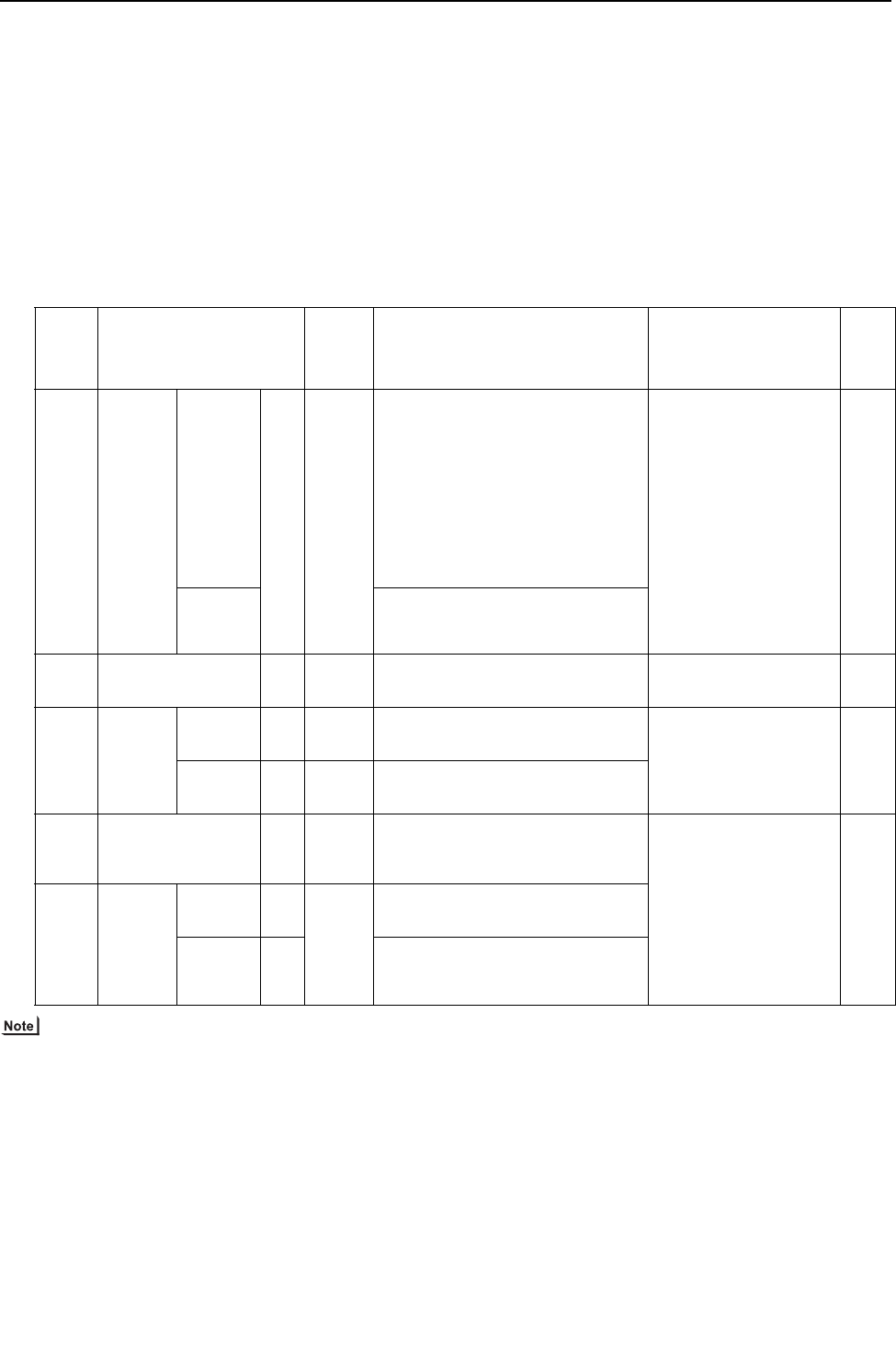
- 52 -
[ II Restrictions ]
GBHWE09080
(4) Wiring method
1) Indoor-heat source transmission line
Same as [5] 8.
Shielded cable connection
Same as [5] 6.
2) Transmission line for centralized control
Same as [5] 9.
Shielded cable connection
Same as [5] 9.
3) ME remote controller wiring
ME remote controller is connectable anywhere on the in-
door-heat source transmission line.
When 2 remote controllers are connected to the sys-
tem
Refer to the section on Switch Setting.
Performing a group operation (including the group
operation of units in different refrigerant circuits).
Refer to the section on Switch Setting.
4) LOSSNAY connection
Same as [5] 9.
5) Switch setting
Address setting is required as follows.
(5) Address setting method
The heat source units in the same refrigerant circuit are automatically designated as OC and OS.
They are designated as OC and OS in the descending order of capacity (ascending order of address if the capacities are the
same).
Proce-
dures Unit or controller
Ad-
dress
setting
range
Setting method Notes
Fac-
tory
set-
ting
1 Indoor
unit
Main unit IC 01 to
50
Assign the smallest address to the main unit
in the group.
In a system with a sub BC controller, make
the settings for the indoor units in the fol-
lowing order.
(i) Indoor unit to be connected to the main BC
controller
(ii) Indoor unit to be connected to sub BC
controller 1
(iii) Indoor unit to be connected to sub BC
controller 2
Make the settings for the indoor units in the
way that the formula "(i) < (ii) < (iii)" is true.
Port number setting is
required
To perform a group op-
eration of indoor units
that have different func-
tions, set the indoor unit
in the group with the
greatest number of
functions as the main
unit.
00
Sub unit Assign sequential numbers starting with the
address of the main unit in the same group
+1. (Main unit address +1, main unit address
+2, main unit address +3, etc.)
2 LOSSNAY LC 01 to
50
Assign an arbitrary but unique address to
each of these units after assigning an address
to all indoor units.
None of these addresses may
overlap any of the indoor unit
addresses.
00
3ME
remote
controller
Main
remote con-
troller
RC 101 to
150
Add 100 to the main unit address in
the group
It is not necessary to set the
100s digit.
To set the address to 200,
set the rotary switches to 00.
101
Sub
remote con-
troller
RC 151 to
200
Add 150 to the main unit address in
the group
4 Heat source unit OC
OS
51 to 100 Assign sequential address to the heat
source units in the same refrigerant circuit.
The heat source units are automatically
designated as OC and OS.(Note)
To set the address to 100,
set the rotary switches to 50.
If the addresses that is as-
signed to the main BC con-
troller overlaps any of the
addresses that are assigned
to the heat source units or to
the sub BC controller, use a
different, unused address
within the setting range.
The use of a sub BC control-
ler requires the connection
of a main BC controller.
00
5 Auxiliary
heat
source
unit
BCcon-
troller (Sub) BS 51 to 100 Assign an address that equals the sum of the
smallest address of the indoor units that are
connected to the sub BC controller and 50.
BC control-
ler (Main) BC OC (or OS if it exists) +1
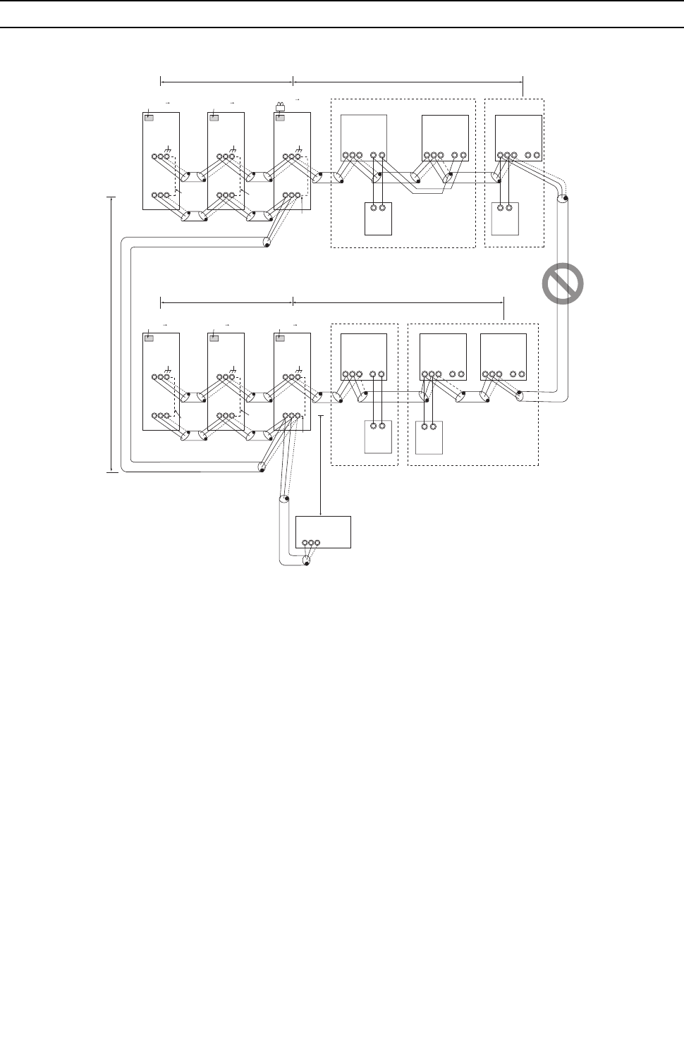
[ II Restrictions ]
53- 53 -
HWE09080 GB
[7] An Example of a System to which both MA Remote Controller and ME Remote Controller are connected
1. PQHY
(1) Sample control wiring
(2) Cautions
1) Be sure to connect a system controller.
2) ME remote controller and MA remote controller cannot
both be connected to the same group of indoor units.
3) Assign to the indoor units connected to the MA remote
controller addresses that are smaller than those of the in-
door units that are connected to the ME remote control-
ler.
4) No more than 2 ME remote controllers can be connected
to a group of indoor units.
5) No more than 2 MA remote controllers can be connected
to a group of indoor units.
6) Do not connect the terminal blocks (TB5) on the indoor
units that are connected to different heat source units
with each other.
7) Replace the power jumper connector of the control board
from CN41 to CN40 on only one of the heat source units.
8) Provide an electrical path to ground for the S terminal on
the terminal block for centralized control on only one of
the heat source units.
9) A transmission booster must be connected to a system
in which the total number of connected indoor units ex-
ceeds 20.
10) A transmission booster is required in a system to which
more than 16 indoor including one or more indoor units
of the 72 model or above are connected.
11) When a power supply unit is connected to the transmis-
sion line for centralized control, leave the power jumper
connector on CN41 as it is (factory setting).
(3) Maximum allowable length
1) Indoor-heat source transmission line
Same as [5] 3.
2) Transmission line for centralized control
Same as [5] 4.
3) MA remote controller wiring
Same as [5] 1.
4) ME remote controller wiring
Same as [5] 1.
5) Maximum line distance via heat source unit
(1.25mm2 or larger)
Same as [5] 4.
IC
TB5 TB
15
1 2
01
IC
TB5 TB
15
1 2
02
IC
TB5 TB
15
1 2
06
106
IC
TB5 TB
15
1 2
05
A B
MA
A B
RC
A B
MA
IC
TB5
1 2
TB
15
IC
TB5 TB
15
1 2
04 03
104
A B
RC
L11 L12
L21 L22
TB3
TB7
S
TB3
TB7
S
TB3
TB7
M1 M2 M1 M2 M1 M2
M1 M2 M1 M2 M1 M2
S
OC
TB3
TB7
S
54
OS1
TB3
TB7
S
55
OS2
TB3
TB7
M1 M2 M1 M2 M1 M2
M1 M2 M1 M2 M1 M2
S
56
L31
A B S
L32
S
M1 M2
S
M1 M2
S
M1 M2
SW2-1 OFF ON
Leave the male
connector on
CN41 as it is.
SW2-1 OFF ON
Leave the male
connector on
CN41 as it is.
OC OS1 OS2
51 52 53
Move the male connector
from CN41 to CN40.
SW2-1 OFF ON
Group Group
Group Group
SW2-1 OFF ON
Leave the male
connector on
CN41 as it is.
SW2-1 OFF ON
Leave the male
connector on
CN41 as it is.
SW2-1 OFF ON
Leave the male
connector on
CN41 as it is.
Note1
System controller
Note1 When only the LM adapter is connected,
leave SW2-1 to OFF (as it is).
Note2 LM adapters require the power supply
capacity of single-phase AC 208/230V.
To be connected
To be left
unconnected
To be left
unconnected
To be left
unconnected
To be left
unconnected
To be left
unconnected
S
M1 M2
S
M1 M2
S
M1 M2

- 54 -
[ II Restrictions ]
GBHWE09080
(4) Wiring method
1) Indoor-heat source transmission line
Same as [5] 1.
Shielded cable connection
Same as [5] 1.
2) Transmission line for centralized control
Same as [5] 4.
Shielded cable connection
Same as [5] 4.
3) MA remote controller wiring
Same as [5] 1.
When 2 remote controllers are connected to the sys-
tem
Same as [5] 1.
Group operation of indoor units
Same as [5] 1.
4) ME remote controller wiring
Same as [6]
When 2 remote controllers are connected to the sys-
tem
Same as [6]
Group operation of indoor units
Same as [6]
5) LOSSNAY connection
Same as [5] 4.
6) Switch setting
Address setting is required as follows.
(5) Address setting method
The heat source units in the same refrigerant circuit are automatically designated as OC, OS1, and OS2.
Proce-
dures Unit or controller
Address
setting
range
Setting method Notes Factory
setting
1Opera-
tion
with the
MA re-
mote
control-
ler
In-
door
unit
Main unit IC 01 to 50 Assign the smallest address
to the main unit in the group.
Assign an address smaller
than that of the indoor unit that
is connected to the ME re-
mote controller.
Enter the same indoor unit
group settings on the system
controller as the ones that
were entered on the MA re-
mote controller.
To perform a group operation
of indoor units that have differ-
ent functions, designate the
indoor unit in the group with
the greatest number of func-
tions as the main unit.
00
Sub unit Assign sequential num-
bers starting with the ad-
dress of the main unit in
the same group +1. (Main
unit address +1, main unit
address +2, main unit ad-
dress +3, etc.)
MA
re-
mote
con-
troller
Main re-
mote con-
troller
MA No
settings
required.
-Main
Sub
remote
controller
MA Sub
remote
controller
Settings to be made ac-
cording to the remote
controller function selec-
tion
2Opera-
tion
with the
ME re-
mote
control-
ler
In-
door
unit
Main unit IC 01 to 50 Assign the smallest ad-
dress to the main unit in
the group.
Enter the indoor unit group set-
tings on the system controller
(MELANS).
Assign an address larger than
those of the indoor units that
are connected to the MA re-
mote controller.
To perform a group operation
of indoor units that have differ-
ent functions, designate the
indoor unit in the group with
the greatest number of func-
tions as the main unit.
00
Sub unit Assign sequential num-
bers starting with the ad-
dress of the main unit in
the same group +1. (Main
unit address +1, main unit
address +2, main unit ad-
dress +3, etc.)
ME re-
mote
con-
troller
Main re-
mote con-
troller
RC 101 to
150
Add 100 to the main unit
address in the group.
It is not necessary to set
the 100s digit.
To set the address to 200,
set the rotary switches to
00.
101
Sub
remote
controller
RC 151 to
200
Add 150 to the main unit
address in the group.
3 LOSSNAY LC 01 to 50 Assign an arbitrary but
unique address to each of
these units after assign-
ing an address to all in-
door units.
None of these addresses
may overlap any of the in-
door unit addresses.
00
4 Heat source unit OC
OS1
OS2
51 to 100 Assign sequential ad-
dress to the heat source
units in the same refriger-
antcircuit. The heat
source units are automat-
ically designated as OC,
OS1, and OS2.(Note)
To set the address to 100,
set the rotary switches to 50.
00
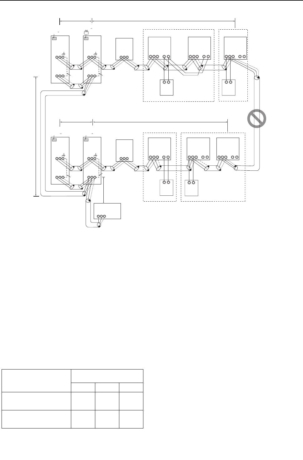
[ II Restrictions ]
55- 55 -
HWE09080 GB
2. PQRY
(1) Sample control wiring
(2) Cautions
1) Be sure to connect a system controller.
2) ME remote controller and MA remote controller cannot both be con-
nected to the same group of indoor units.
3) Assign to the indoor units connected to the MA remote controller ad-
dresses that are smaller than those of the indoor units that are con-
nected to the ME remote controller.
4) No more than 2 ME remote controllers can be connected to a group
of indoor units.
5) No more than 2 MA remote controllers can be connected to a group
of indoor units.
6) Do not connect the terminal blocks (TB5) on the indoor units that are
connected to different heat source units with each other.
7) Replace the power jumper connector of the control board from CN41
to CN40 on only one of the heat source units.
8) Provide an electrical path to ground for the S terminal on the terminal
block for centralized control on only one of the heat source units.
9) When the number of the connected indoor units is as shown in the
table below, one or more transmission boosters (sold separately)
are required.
To connect two transmission boosters, connect them in parallel.
(Observe the maximum number of connectable indoor units that are
listed in the specifications for each heat source unit.)
The left table shows the number of transmission boost-
ers that is required by the system with three BC control-
lers. For each BC controller that is subtracted from the
above-mentioned system, two additional indoor units
can be connected.
10) When a power supply unit is connected to the transmis-
sion line for centralized control, leave the power jumper
connector on CN41 as it is (factory setting).
(3) Maximum allowable length
1) Indoor-heat source transmission line
Same as [5] 8.
2) Transmission line for centralized control
Same as [5] 9.
3) MA remote controller wiring
Same as [5] 6.
4) ME remote controller wiring
Same as [6] 2.
5) Maximum line distance via heat source unit
(1.25 mm2 or larger)
Same as [5] 4.
IC
TB5
S
TB
15
12
01
IC
TB5
S
TB
15
12
02
IC
TB5
S
TB
15
12
06
106
IC
TB5
S
TB
15
12
05
A1 B2
MA
A1 B2
RC
A1 B2
MA
IC
TB5
S12
TB
15
IC
TB5
S
TB
15
12
0403
104
A1 B2
RC
OC
TB3
TB7
S
51
OS
TB3
TB7
S
52
OC
TB3
TB7
S
54
OS
TB3
TB7
S
55
L31
ABS
L32
SW2-1 OFF ON
Leave the male
connector on
CN41 as it is.
SW2-1 OFF ON
Leave the male
connector on
CN41 as it is.
To be left
unconnected
To be left
unconnected
To be left
unconnected
To be connected
System controller
Note1
*1 When only the LM adapter is connected, leave SW2-1 to OFF (as it is).
*2 LM adapters require the power supply capacity of single-phase AC 208 - 230V.
M1M2
M1M2
M1M2
M1M2
M1M2 M1 M2 M1 M2
M1M2M1 M2M1M2
M1 M2M1 M2M1 M2
M1 M2M1 M2
S
BC
TB02
53
S
BC
TB02
56
L22
L21
L12
L11
SW2-1 OFF ON
Leave the male
connector on
CN41 as it is. SW2-1 OFF ON
Move the male connector
from CN41 to CN40.
Group Group
GroupGroup
M1M2
Number of transmission booster
(sold separately) required
1 unit 2 units 3 units
When the P72 and P96 models
are not included in the connected
indoor units
15 - 34
units
35 - 50
units -
When the P72 or P96 model is in-
cluded in the connected indoor
units
11 - 26
units
27 - 42
units
43 - 50
units

- 56 -
[ II Restrictions ]
GBHWE09080
(4) Wiring method
1) Indoor-heat source transmission line
Same as [5] 8.
Shielded cable connection
Same as [5] 6.
2) Transmission line for centralized control
Same as [5] 9.
Shielded cable connection
Same as [5] 9.
3) MA remote controller wiring
When 2 remote controllers are connected to the sys-
tem
Group operation of indoor units
Same as [5] 6.
4) ME remote controller wiring
When 2 remote controllers are connected to the sys-
tem
Group operation of indoor units
Same as [6] 1.
5) LOSSNAY connection
Same as [5] 9.
6) Switch setting
Address setting is required as follows.

[ II Restrictions ]
57- 57 -
HWE09080 GB
(5) Address setting method
The heat source units in the same refrigerant circuit are automatically designated as OC and OS.
They are designated as OC and OS in the descending order of capacity (ascending order of address if the capacities are the same).
Pro-
ce-
dure
s
Unit or controller
Ad-
dress
set-
ting
range
Setting method Notes
Facto-
ry set-
ting
1 Opera-
tion with
the
MA re-
mote
controller
In-
door
unit
Main
unit
IC 01 to
50
Assign the smallest address to
the main unit in the group.
In a system with a sub BC con-
troller, make the settings for the
indoor units in the following or-
der.
(i) Indoor unit to be connected to
the main BC controller
(ii) Indoor unit to be connected to
sub BC controller 1
(iii) Indoor unit to be connected to
sub BC controller 2
Make the settings for the indoor
units in the way that the formula "(i)
< (ii) < (iii)" is true.
Assign an address smaller than that of
the indoor unit that is connected to the
ME remote controller.
Enter the same indoor unit group set-
tings on the system controller as the
ones that were entered on the MA re-
mote controller.
To perform a group operation of indoor
units that have different functions, des-
ignate the indoor unit in the group with
the greatest number of
Port number setting is required
00
Sub
unit
IC 01 to
50
Assign sequential numbers start-
ing with the address of the main
unit in the same group +1. (Main
unit address +1, main unit address
+2, main unit address +3, etc.)
MA
re-
mote
con-
troller
Main re-
mote
control-
ler
MA No
set-
tings re-
quired.
-Main
Sub
remote
control-
ler
MA Sub
remote
control-
ler
Settings to be made according
to the remote controller func-
tion selection
2 Opera-
tion with
the
ME re-
mote
controller
In-
door
unit
Main
unit
IC 01 to
50
Assign the smallest address
to the main unit in the group.
Assign an address higher than those of
the indoor units that are connected to
the MA remote controller.
Make the initial settings for the indoor
unit group settings via the system con-
troller.
To perform a group operation of indoor
units that have different functions, des-
ignate the indoor unit in the group with
the greatest number of functions as the
main unit.
Port number setting is required.
Addresses that are assigned to the in-
door units that are connected to the sub
BC controller should be higher than the
addresses that are assigned to the in-
door units that are connected to the
main BC controller.
00
Sub
unit
IC 01 to
50
Assign sequential numbers
starting with the address of the
main unit in the same group
+1. (Main unit address +1,
main unit address +2, main
unit address +3, etc.)
ME
re-
mote
con-
troller
Main re-
mote
control-
ler
RC 101 to
150
Add 100 to the main unit ad-
dress in the group.
It is not necessary to set the 100s
digit.
To set the address to 200, set it to
00.
101
Sub
remote
control-
ler
RC 151 to
200
Add 150 to the main unit ad-
dress in the group.
3 LOSSNAY LC 01 to
50
Assign an arbitrary but unique
address to each of these units
after assigning an address to
all indoor units.
None of these addresses may over-
lap any of the indoor unit addresses.
00
4 Heat source unit OC
OS
51 to
100
Assign sequential address to the
heat source units in the same
refrigerant circuit.
The heat source units are auto-
matically designated as OC and
OS.(Note)
To set the address to 100, set it to 50.
If the addresses that is assigned to the
main BC controller overlaps any of the
addresses that are assigned to the heat
source units or to the sub BC controller,
use a different, unused address within
the setting range.
The use of a sub BC controller requires
the connection of a main BC controller.
00
5 Auxiliary
heat
source
unit
BCcontroller (Sub) BS 51 to
100
Assign an address that equals the
sum of the smallest address of the
indoor units that are connected to
the sub BC controller and 50.
BC controller
(Main) BC OC (or OS if it exists) +1
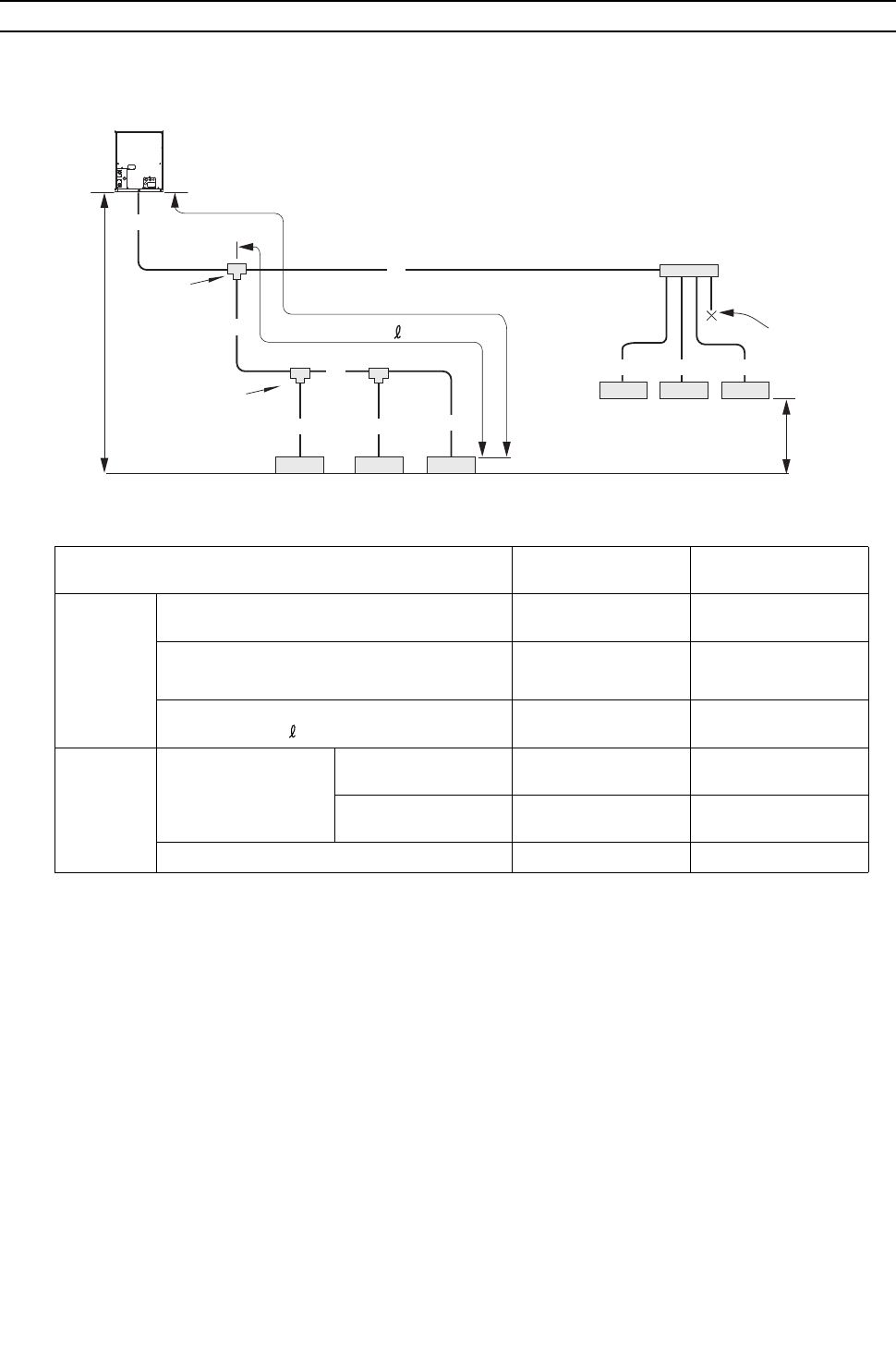
[ II Restrictions ]
- 58 -
HWE09080 GB
[8] Restrictions on Pipe Length
(1) End branching <PQHY>
P72 - P120 models
Unit: m [ft]
Operation Pipe sections Allowable length of
pipes
Length Total pipe length A+B+C+D
+a+b+c+d+e+f
300 [984] or less
Total pipe length (L) from the heat source unit to
the farthest indoor unit
A+B+C+c or
A+D+f
165 [541] or less
(Equivalent length 190
[623] or less)
Total pipe length from the first branch to the far-
thest indoor unit ( )
B+C+c or
D+f
40 [131] or less
Height
difference
Between indoor and
heat source units
Heat source unit above
indoor unit
H 50 [164] or less
Heat source unit below
indoor unit
H' 40 [131] or less
Between indoor units h 15 [49] or less
L
B
e
h
f
6
1
a c
b
3
2
5
A
D
C d
4
H
H
'
Branch joint
Indoor Indoor Indoor
Indoor Indoor Indoor
cap
Branch header
(Heat source unit above indoor unit)
(Heat source unit below indoor unit)
Heat source unit
First branch
(Branch joint)
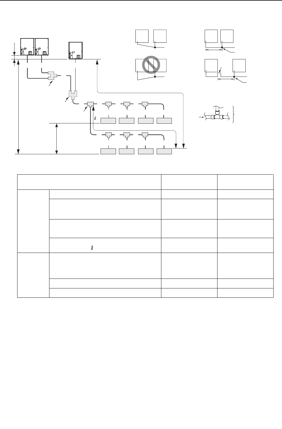
[ II Restrictions ]
- 59 -
HWE09080 GB
P144 - P360 models
Unit: m [ft]
Operation Pipe sections Allowable length of
pipes
Length Between heat source units A+B+C+D 10 [32] or less
Total pipe length A+B+C+D+E+F+G+I+J
+K+M+a+b+c+d+e+f+g
+i
300 [984] or less
Total pipe length (L) from the heat source unit to
the farthest indoor unit
A(B)+C+E+J+K+M+i 165 [541] or less
(Equivalent length 190
[623] or less)
Total pipe length from the first branch to the far-
thest indoor unit ( )
G+I+J+i 40 [131] or less
Height
difference
Between indoor and heat source units H 50 [164] or less
(40 [131] or below if
heat source unit is be-
low indoor unit)
Between indoor units h1 15 [49] or less
Between heat source units h2 0.1[0.3] or less
Indoor Indoor Indoor Indoor
Indoor Indoor Indoor Indoor
E
L
H
a
h1
h2
b
2
1
c
3
d
4
e
5
f
6
g
7
i
8
C
E F G I
J K M
B D A
First branch
(Note)
To downstream units
Note : "Total sum of downstream unit model numbers"
in the table is the sum of the model numbers
of the units after point E in the figure.
Note1 Install the pipe that connects the branch pipe and the heat source units
in the way that it has a downward inclination toward the branch pipe.
Provide a trap on the pipe (gas pipe only) within 2 m from the
joint pipe if the total length of the pipe that connects the joint
pipe and the heat source unit exceeds 2 m.
Downward inclination To indoor unit
To indoor unit
To indoor unit
Joint pipe
Joint pipe
Trap
(gas pipe
only)
To indoor unit
Upward inclination
First liquid refrigerant distributor
First gas refrigerant distributor
Second gas refrigerant distributor
Second liquid refrigerant distributor
2m [6ft]
2m [6ft] Max.
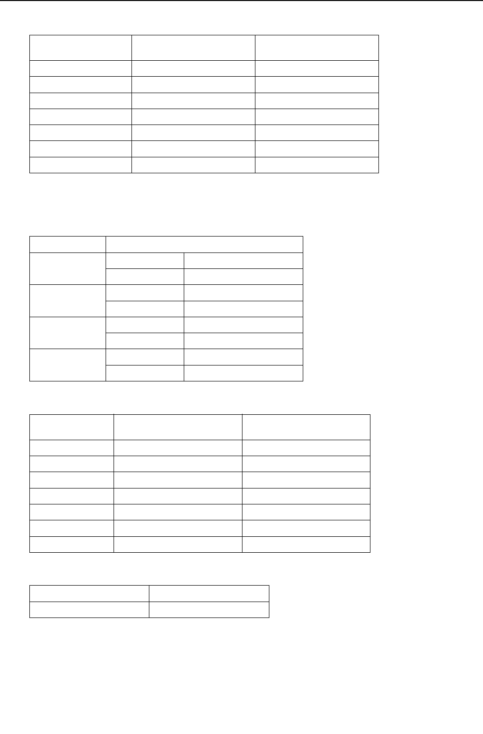
[ II Restrictions ]
- 60 -
HWE09080 GB
1. Refrigerant pipe size <PQHY>
(1) Diameter of the refrigerant pipe between the heat source unit and the first branch (heat source unit pipe size)
(2) Size of the refrigerant pipe between the first branch and the indoor unit (indoor unit pipe size)
(3) Size of the refrigerant pipe between the branches for connection to indoor units
(4) Size of the refrigerant pipe between the first distributor and the second distributor
Heat source unit set
name
Liquid pipe size (mm) [inch] Gas pipe size (mm) [inch]
P72 model ø9.52 [3/8"] ø19.05 [3/4"]
P96 model ø9.52 [3/8"]*1
*1. Use ø12.7 [1/2"] pipes if the piping length exceeds 90 m [295 ft].
ø22.2 [7/8"]
P120 model ø9.52 [3/8"]*2
*2. Use ø12.7 [1/2"] pipes if the piping length exceeds 40 m [131 ft].
ø22.2 [7/8"]
P144 model ø12.7 [1/2"] ø28.58 [1-1/8"]
P168 - 240 model ø15.88 [5/8"] ø28.58 [1-1/8"]
P264 - 312models ø19.05 [3/4"] ø34.93 [1-3/8"]
P336- 360 models ø19.05 [3/4"] ø41.28 [1-5/8"]
Indoor unit model Pipe diameter (mm) [inch]
06 - 15 models Liquid pipe ø6.35 [1/4"]
Gas pipe ø12.7 [1/2"]
18 - 54 models Liquid pipe ø9.52 [3/8"]
Gas pipe ø15.88 [5/8"]
72 model Liquid pipe ø9.52 [3/8"]
Gas pipe ø19.05 [3/4"]
96 model Liquid pipe ø9.52 [3/8"]
Gas pipe ø22.2 [7/8"]
Total capacity of the
downstream units
Liquid pipe size (mm) [inch] Gas pipe size (mm) [inch]
- 54 ø9.52 [3/8"] ø15.88 [5/8"]
P55 - P72 ø9.52 [3/8"] ø19.05 [3/4"]
P72 - P108 ø9.52 [3/8"] ø22.2 [7/8"]
P109 - P144 ø12.7 [1/2"] ø28.58 [1-1/8"]
P145 - P240 ø15.88 [5/8"] ø28.58 [1-1/8"]
P241 - P308 ø19.05 [3/4"] ø34.93 [1-3/8"]
P309 - ø19.05 [3/4"] ø41.28 [1-5/8"]
Liquid pipe size (mm) [inch] Gas pipe size (mm) [inch]
ø19.05 [3/4"] ø34.93 [1-3/8"]
[ II Restrictions ]
- 61 -
HWE09080 GB
(5) Size of the refrigerant pipe between the first distributor or the second distributor and heat source units
Heat source unit
model
Composing unit models Liquid pipe (mm) [inch] Gas pipe (mm) [inch]
P144 P72 ø9.52 [3/8"] ø19.05 [3/4"]
P72
P168 P96 ø9.52 [3/8"] ø22.2 [7/8"]
P72
P192 P96
P96
P216 P120 ø12.7 [1/2"] ø22.2 [7/8"]
P96
P240 P120
P120
P264 P96 ø12.7 [1/2"] ø22.2 [7/8"]
P96
P72
P288 P96
P96
P96
P312 P120
P96
P96
P336 P120
P120
P96
P360 P120
P120
P120
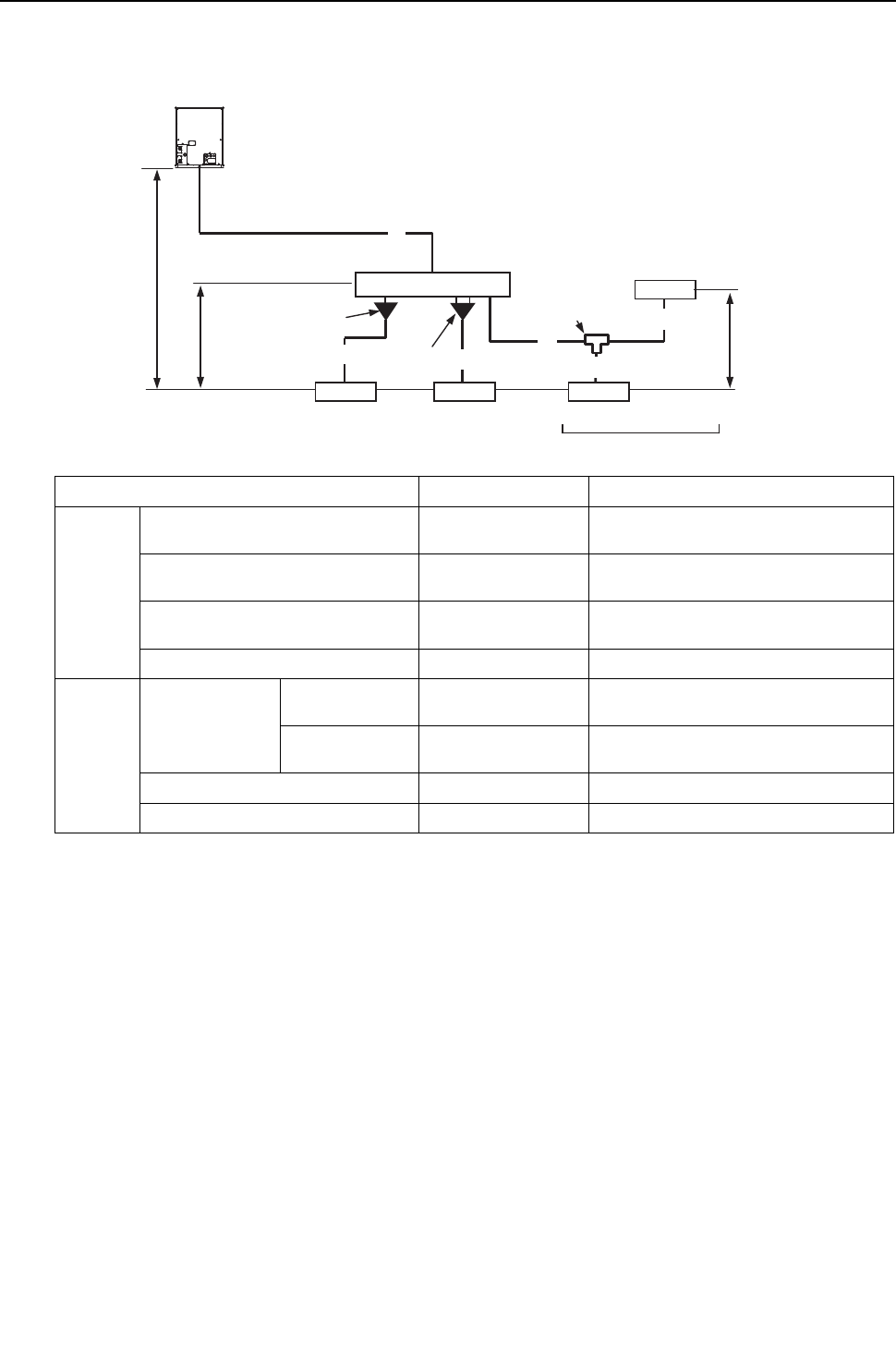
[ II Restrictions ]
- 62 -
HWE09080 GB
(1) System that requires 16 BC controller ports or fewer <System with only the main BC controller or standard BC con-
troller> <PQRY>
Unit: m [ft]
Operation Pipe sections Allowable length of pipes
Length Total pipe length A+B+a+b+c+d Refer to the restrictions on the total piping
length in the graph on the next page.
Total pipe length from the heat source
unit to the farthest indoor unit
A+B+d 165 [541] or less
(Equivalent length 190 [623] or less)
Between heat source unit and BC con-
troller
A 110 [360] or less
Between BC controller and indoor unit B+d 40 [131] or less*1
*1. When the overall pipe length between the BC controller and the farthest indoor unit exceeds 40m [131ft], observe the
restrictions in the figure titled "Restrictions on pipe length" below (except the P96 model).
Height
difference Between indoor
and heat source
units
Heat source unit
above indoor unit
H 50 [164] or less
Heat source unit
below indoor unit
H' 40 [131] or less
Between indoor unit and BC controller h1 15[49](10[32]) or less*2
*2. When the capacity of the connected indoor units is P72 or above, use the figures in the parentheses as a reference.
Between indoor units h2 15[49](10[32]) or less *2
ab
HH'
h1
A
h2
Heat source unit
BC controller
Reducer (P06 - P18 models)
(Supplied with the BC Controller)
B
d
c
Junction pipe
(CMY-R160-J)
*Use a main BC controller when connecting the heat source units of
P144 model or above.
Branch joint
(CMY-Y102S-G2)
Indoor Indoor Indoor
Indoor
(P06 - P54 models) (P72 or P96 model) Maximum of 3 units per port
Total capacity of P54 or below
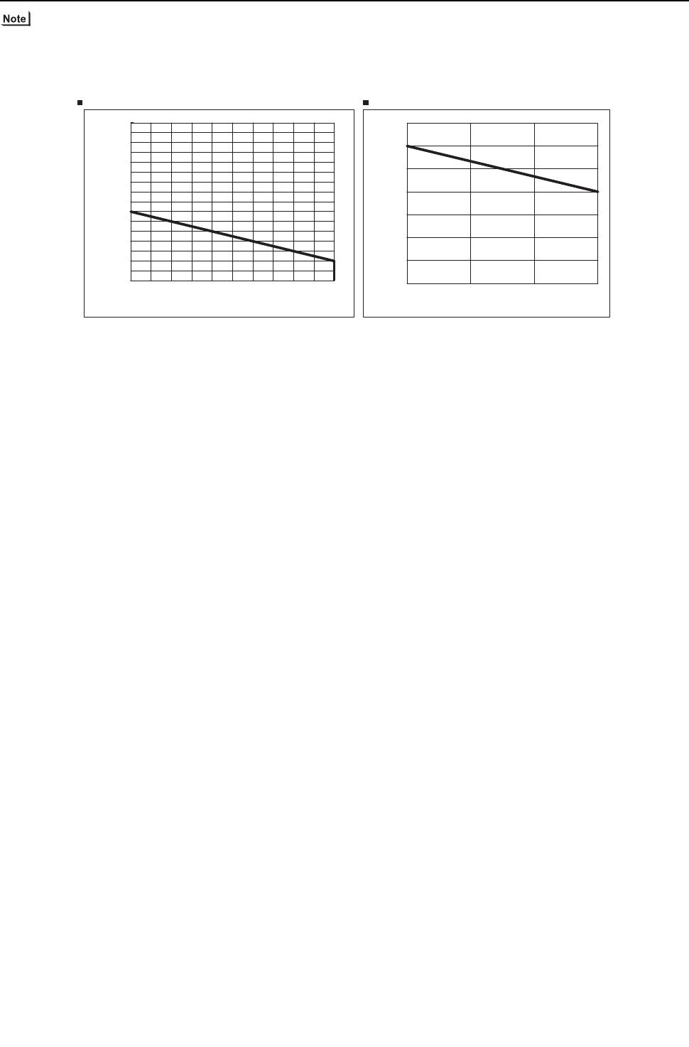
[ II Restrictions ]
- 63 -
HWE09080 GB
1) To connect the P72 or P96 model of indoor units, use an optional junction pipe kit (Model: CMY-R160-J) and merge the two
ports before connecting them.
2) Do not connect the P72 or P96 model of indoor units and other models of indoor units at the same port.
3) All the units that are connected to the same ports can only be operated in the same operation mode (cooling/heating).
0
10
20
30
40
50
60
70
0 5 10 15
Pipe length between main BC
controller and farthest indoor unit (m[ft])
Height difference between main BC controller and farthest indoor unit (m[ft])
The height difference and the pipe length between BC controller and indoor units
Restrictions on pipe length [PQRY-P72, P96, P120THMU-A/YHMU-A]
1000
900
800
700
600
500
400
300
200
10 20 30 40 50 60 70 80 90
100 110
Aggregate length of all pipes(m[ft])
Pipe length between heat source unit and BC controller (m[ft])
[32] [64] [98] [131] [164] [196] [229] [262] [295] [328] [360]
[3280]
[2952]
[2624]
[2296]
[1968]
[1640]
[1312]
[984]
[656]
[32]
[16] [32] [49]
[64]
[98]
[131]
[164]
[196]
[229]
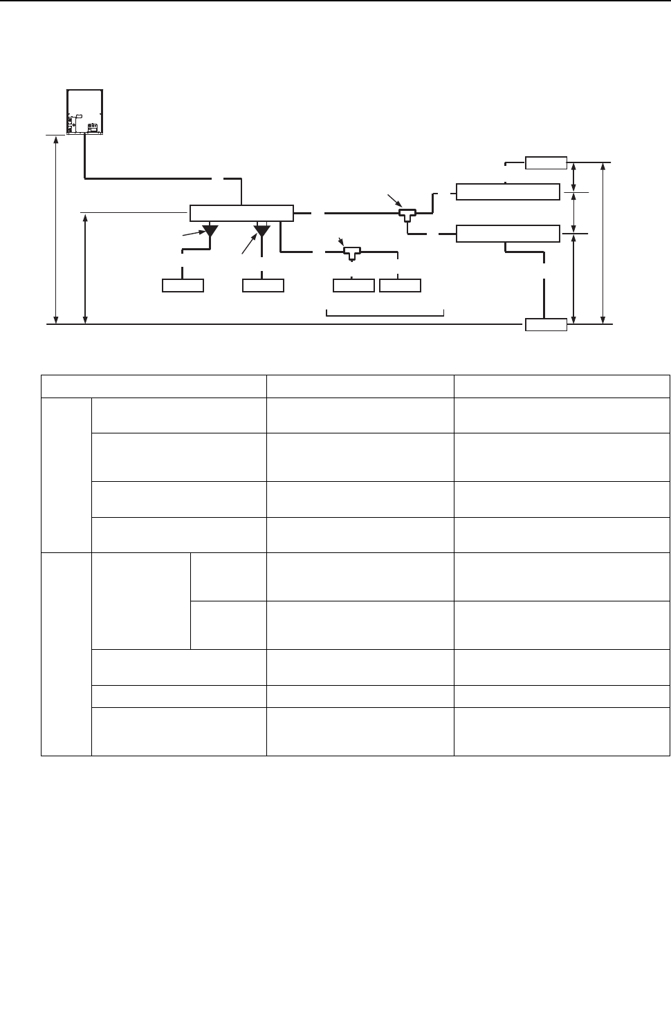
[ II Restrictions ]
- 64 -
HWE09080 GB
(2) System that requires more than 16 BC controller ports or with multiple BC controllers <Heat source unit P120 model
or below>
Unit: m [ft]
Operation Pipe sections Allowable length of pipes
Length Total pipe length A+B+C+D+E+a+b+c+d+e+f Refer to the restrictions on the total pip-
ing length in the graphon the next page.
Total pipe length from the heat
source unit to the farthest in-
door unit
A+C+E+f 165 [541] or less
(Equivalent length 190 [623] or less)
Between heat source unit and
BC controller
A 110 [360] or less
Between BC controller and in-
door unit
B+d or C+D+e
or C+E+f
40 [131] or less*1
*1. When the overall pipe length between the BC controller and the farthest indoor unit exceeds 40m [131ft], observe the
restrictions in the figure titled "Restrictions on pipe length" below (except the P96 model).
Height
differ-
ence Between indoor
and heat source
units
Heat source
unit above
indoor unit
H 50 [164] or less
Heat source
unit below
indoor unit
H' 40 [131] or less
Between indoor unit and BC
controller
h1 15 [49](10[32]) or less*2
*2. When the capacity of the connected indoor units is P72 or above, use the figures in the parentheses as a reference.
Between indoor units h2 15 [49](10[32]) or less *2
Between the BC controller
(main or sub) and the sub BC
controller
h3 15 [49] or less
Branch joint
(CMY-Y202-G2)
(CMY-Y102L-G2)
(CMY-Y102S-G2)
Branch joint
(
CMY-Y102S-G2)
a
C
b
HH'
h1 h1
B
cdf
h3
D
E
Aeh1
h2
Heat source unit
BC controller (main)
BC controller (sub)
BC controller (sub)
Indoor Indoor Indoor Indoor
Indoor
Indoor
Reducer (P06 - P18 models)
(Supplied with the BC Controller)
(P06 - P54 models) (P72 or P96 model) Maximum of 3 units per port
Total capacity of P54 or below
Junction pipe
(CMY-R160-J)
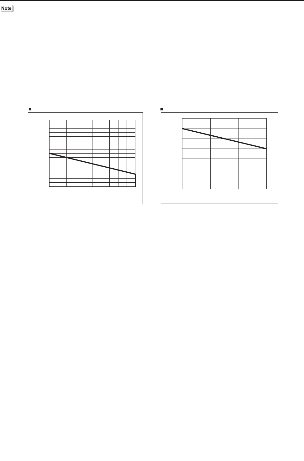
[ II Restrictions ]
- 65 -
HWE09080 GB
1) A system that requires more than 16 BC controller ports requires two or three BC controllers (main and sub), and three pipes
will be used between the main and the sub BC controllers.
2) When connecting two sub BC controllers, observe the maximum allowable length in the table above.
3) When connecting two sub BC controllers, install them in parallel.
4) To connect the P72 or P96 model of indoor units, use an optional junction pipe kit (Model: CMY-R160-J) and merge the two
ports before connecting them.
5) Do not connect the P72 or P96 model of indoor units and other models of indoor units at the same port.
6) All the units that are connected to the same ports can only be operated in the same operation mode (cooling/heating).
7) The maximum capacity of the indoor units that is connectable to the CMB-P-NU-GB types of sub BC controllers is P126 or
below (when two GB type controllers are connected P126 or below for both combined).
The maximum total capacity of indoor units that is connectable to the sub BC controller CMB-P1016NU-HB is P126 or below.
If at least one CMB-P1016NU-HB unit is connected, the maximum total capacity of connectable indoor units to a system with
two sub controllers is P168 or below.
0
10
20
30
40
50
60
70
0 5 10 15
1000
900
800
700
600
500
400
300
200
10 20 30 40 50 60 70 80 90
100 110
Pipe length between main BC
controller and farthest indoor unit (m[ft])
Height difference between main BC controller and farthest indoor unit (m[ft])
The height difference and the pipe length between BC controller and indoor units
Restrictions on pipe length [PQRY-P72, P96, P120THMU-A/YHMU-A]
Aggregate length of all pipes(m[ft])
Pipe length between heat source unit and BC controller (m[ft])
[32] [64] [98] [131] [164] [196] [229] [262] [295] [328] [360]
[3280]
[2952]
[2624]
[2296]
[1968]
[1640]
[1312]
[984]
[656]
[32]
[16] [32] [49]
[64]
[98]
[131]
[164]
[196]
[229]
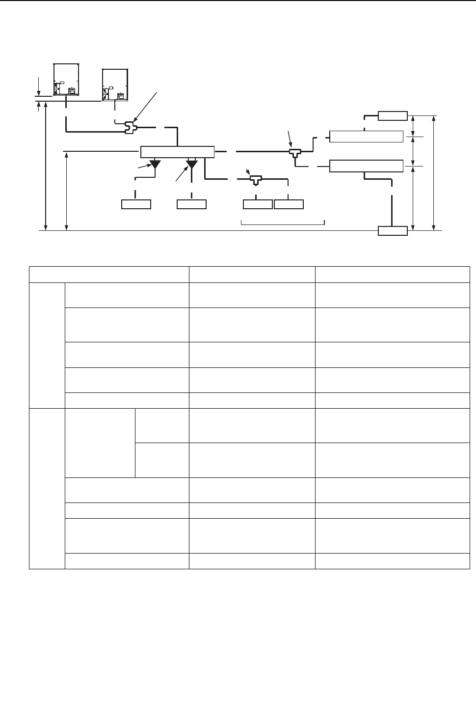
[ II Restrictions ]
- 66 -
HWE09080 GB
(3) System that requires more than 16 BC controller ports or with multiple BC controllers <Heat source unit P144 model
or above>
Unit: m [ft]
Operation Pipe sections Allowable length of pipes
Length Total pipe length F+G+A+B+C+D+E+a+b+c+d+e
+f
Refer to the restrictions on the total pip-
ing length in the graph on the next page.
Total pipe length from the heat
source unit to the farthest in-
door unit
F(G)+A+C+E+f 165 [541] or less
(Equivalent length 190 [623] or less)
Between heat source unit and
BC controller
F(G)+A 110 [360] or less
Between BC controller and in-
door unit
B+d or C+D+e
or C+E+f
40 [131] or less*1
*1. When the overall pipe length between the BC controller and the farthest indoor unit exceeds 40m [131ft], observe
the restrictions in the figure titled "Restrictions on pipe length" below (except the P96 model).
Between heat source units F+G 5 [16] or less
Height
differ-
ence Between indoor
and heat source
units
Heat source
unit above
indoor unit
H 50 [164] or less
Heat source
unit below
indoor unit
H' 40 [131] or less
Between indoor unit and BC
controller
h1 15 [49](10[32]) or less*2
*2. When the capacity of the connected indoor units is P72 or above, use the figures in the parentheses as a reference.
Between indoor units h2 15 [49](10[32]) or less *2
Between the BC controller
(main or sub) and the sub BC
controller
h3 15 [49] or less
Between heat source units h4 0.1 [0.3] or less
h1
h3
h1
h2
f
D
E
e
Branch joint : CMY-Q100VBK
On the low-pressure side, the twinning kit connects to the pipes on site inside the heat source unit.
When different capacity units are combined, connect the kit to the larger capacity heat source unit.
a
C
b
B
cd
A
G
F
h4
Heat source unit
1
Heat source unit
2
HH'
h1
BC controller (main)
Indoor Indoor Indoor Indoor
Indoor
Indoor
BC controller (sub)
BC controller (sub)
Branch joint
(CMY-Y202-G2)
(CMY-Y102L-G2)
(CMY-Y102S-G2)
Branch joint
(
CMY-Y102S-G2)
(P06 - P54 models) (P72 or P96 model) Maximum of 3 units per port
Total capacity of P54 or below
Reducer (P06 - P18 models)
(Supplied with the BC Controller)
Junction pipe
(CMY-R160-J)
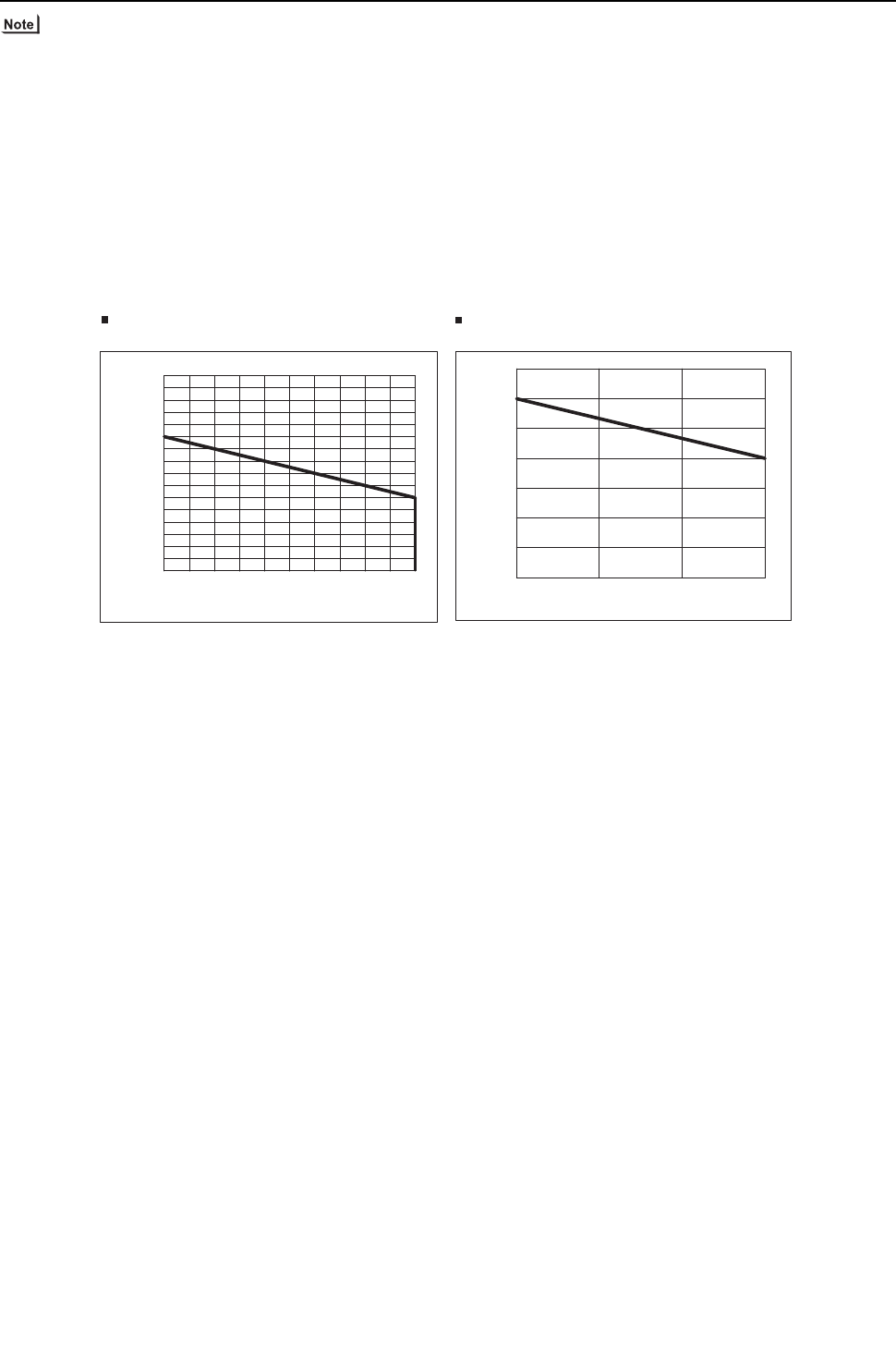
[ II Restrictions ]
- 67 -
HWE09080 GB
1) A system that requires more than 16 BC controller ports requires two or three BC controllers (main and sub), and three pipes
will be used between the main and the sub BC controllers.
2) When connecting two sub BC controllers, observe the maximum allowable length in the table above.
3) When connecting two sub BC controllers, install them in parallel.
4) To connect the P72 or P96 model of indoor units, use an optional junction pipe kit (Model: CMY-R160-J) and merge the two
ports before connecting them.
5) Do not connect the P72 or P96 model of indoor units and other models of indoor units at the same port.
6) All the units that are connected to the same ports can only be operated in the same operation mode (cooling/heating).
7) The maximum capacity of the indoor units that is connectable to the CMB-P-NU-GB types of sub BC controllers is P126 or
below (when two GB type controllers are connected, P126 or below for both combined).
The maximum total capacity of indoor units that is connectable to the sub BC controller CMB-P1016NU-HB is P126 or below.
If at least one CMB-P1016NU-HB unit is connected, the maximum total capacity of connectable indoor units to a system with
two sub controllers is P168 or below.
0
10
20
30
40
50
60
70
0 5 10 15
[PQRY-P144, P168, P192, P216, P240THMU-A/YHMU-A]
The height difference and the pipe length between
BC controller and indoor units
Restrictions on pipe length
Aggregate length of all pipes(m[ft])
Pipe length between main BC
controller and farthest indoor unit (m[ft])
Height difference between main BC controller and farthest indoor unit (m[ft])
[32]
[16] [32] [49]
[64]
[98]
[131]
[164]
[196]
[229]
110
1000
900
800
700
600
500
400
300
200
10 20 30 40 50 60 70 80 90
100
Pipe length between heat source unit and BC controller (m[ft])
[32] [64] [98] [131] [164] [196] [229] [262] [295] [328] [360]
[3280]
[2952]
[2624]
[2296]
[1968]
[1640]
[1312]
[984]
[656]
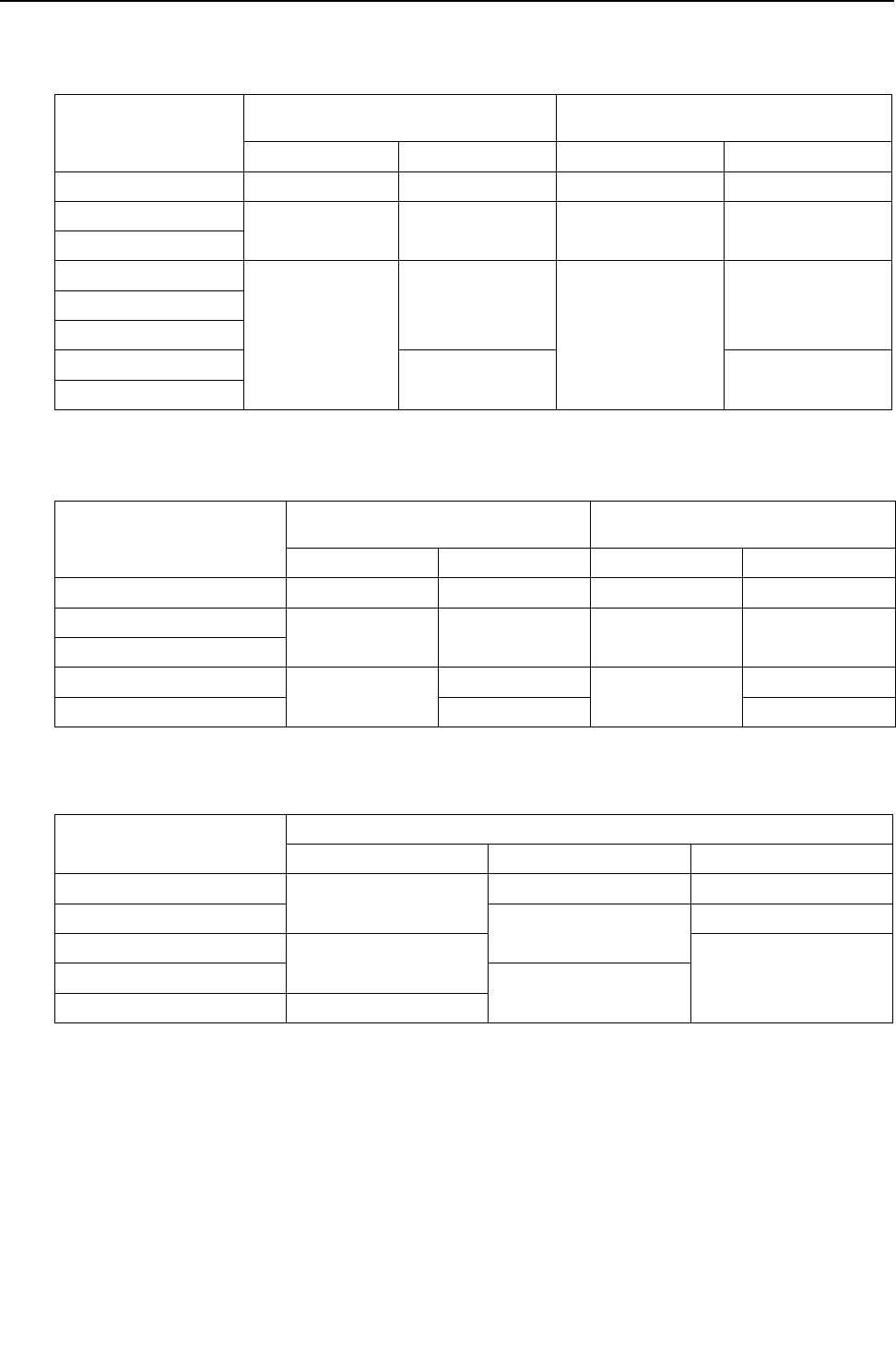
[ II Restrictions ]
- 68 -
HWE09080 GB
2. Refrigerant pipe size <PQRY>
(1) Between heat source unit and the first twinning pipe (Part A)
(2) Between BC controller and indoor unit (Sections a, b, c, d, e, and f )
(3) Between the main and sub BC controllers (Section C)
Select the proper size pipes for the main unit based on the total capacity of the indoor units that are connected to both sub
BC controllers. Select the proper size pipes for the sub controller side based on the total capacity of the indoor units that are
connected to the sub controller.
Unit : mm [inch]
Heat source unit
Refrigerant pipe size Connection to heat source unit and BC control-
ler
Low-pressure pipe High-pressure pipe Low-pressure pipe High-pressure pipe
P72 ø19.05 [3/4"] ø15.88 [5/8"] ø19.05 [3/4"] ø15.88 [5/8"]
P96 ø22.2 [7/8"] ø19.05 [3/4"] ø22.2 [7/8"] ø19.05 [3/4"]
P120
P144
ø28.58 [1-1/8"]
ø22.2[7/8"]
ø28.58 [1-1/8"]
ø22.2 [7/8"]P168
P192
P216 ø28.58 [1-1/8"] ø28.58 [1-1/8"]
P240
Unit : mm [inch]
Indoor unit
Refrigerant pipe size Indoor unit connection
(Flare connection for all models)
Liquid pipe Gas pipe Liquid pipe Gas pipe
P06, P08, P12, P15, P18 ø6.35 [1/4"] ø12.7 [1/2"] ø6.35 [1/4"] ø12.7 [1/2"]
P24, P27, P30 ø9.52 [3/8"] ø15.88 [5/8"] ø9.52 [3/8"] ø15.88 [5/8"]
P36, P48, P54
P72 ø12.7 [1/2"] ø19.05 [3/4"] ø12.7 [1/2"] ø19.05 [3/4"]
P96 ø22.2[7/8"] ø22.2[7/8"]
Unit : mm [inch]
Indoor unit Refrigerant pipe size (Brazed connection on all models )
Liquid pipe High-pressure gas pipe Low-pressure gas pipe
- P72 ø9.52 [3/8"] ø15.88 [5/8"] ø19.05 [3/4"]
P73 - P108 ø19.05 [3/4"] ø22.2 [7/8"]
P109 - P126 ø12.7 [1/2"] ø28.58 [1-1/8"]P127 - P144 ø22.2 [7/8"]
P145 - P168 ø15.88 [5/8"]
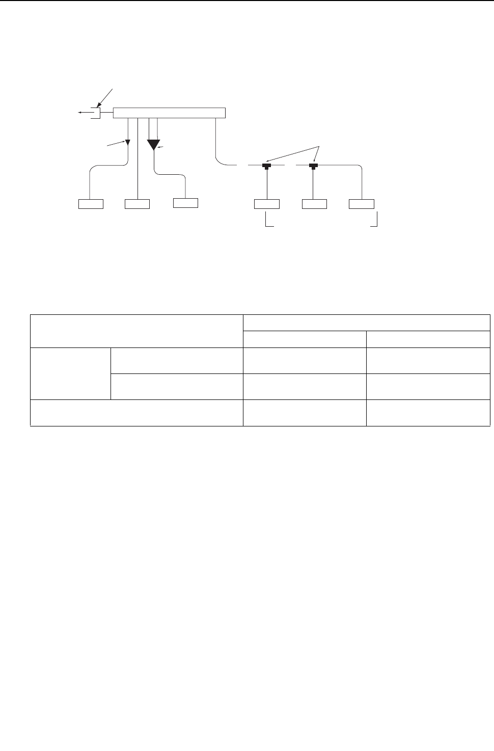
[ II Restrictions ]
- 69 -
HWE09080 GB
3. Connecting the BC controller <PQRY>
(1) Size of the pipe that fits the standard BC controller ports
P72 - P120 models
* BC controllers can only be connected to P72 - P120 models of heat source units.
Unit : mm [inch]
Operation Pipe sections
High-pressure side (liquid) Low-pressure side (gas)
Heat source unit
side
PQRY-P72THMU-A/YHMU-A ø15.88 [5/8"]
(Brazed connection)
ø19.05 [3/4"]
(Brazed connection)
PQRY-P96THMU-A/YHMU-A
PQRY-P120THMU-A/YHMU-A
ø19.05 [3/4"]
(Brazed connection)
ø22.2 [7/8"]
(Brazed connection)
Indoor unit side ø9.52 [3/8"]
(Flare connection)
ø15.88 [5/8"]
(Flare connection)
IndoorIndoorIndoor
Indoor
IndoorIndoor
BC controller
Maximum of 3 units per port
Total capacity of P54 or below
(All units connected to the same port
must be in the same operating mode.)
Branch joint (Model name:CMY-Y102S-G2)
(Optional accessory)
*2
Junction pipe kit
(Model name:
CMY-R160-J)
(Optional accessory)
P18 model or below P24-P54 models P72 or P96 model
The ports of the BC controller accommodates the pipes on P24-P54 models of indoor units.
To connect other types of indoor units, follow the procedure below.
3*
AB
*1
Reducer
(Standard
supplied parts)
To heat
source unit
Connection: Brazed connection
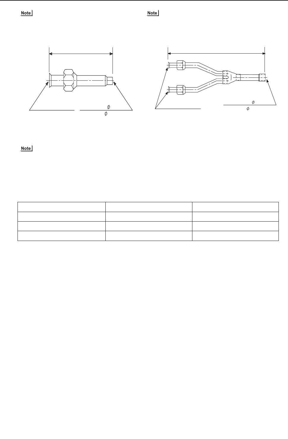
[ II Restrictions ]
- 70 -
HWE09080 GB
1) To connect P06 - P18 models of indoor units use
the reducer that is supplied with the BC controller.
2) To connect P36 - P96 models of indoor units (or when the
total capacity of indoor units exceeds P31), use a junction
pipe kit and merge the two nozzles.
3) To connect multiple indoor units to a port (or to a junction pipe)
Maximum total capacity of connected indoor units: P54 or below (in a system with a junction pipe: P96 or below)
Maximum number of connectable indoor units: 3 units
Branch joint: Use CMY-Y102S-G2 (optional accessory).
Refrigerant pipe selection (size of the pipes in sections A and B in the figure above): Select the proper size pipes
based on the total capacity of the downstream indoor units, using the table below as a reference.
Unit : mm [inch]
Total capacity of indoor units Liquid pipe Gas pipe
P54 or below ø9.52 [3/8"] ø15.88 [5/8"]
P55 - P72 ø9.52 [3/8"] ø19.05 [3/4"]
P73 - P96 ø9.52 [3/8"] ø22.2 [7/8"]
Liquid pipe side: 6.35[1/4"]ID
Gas pipe side: 12.7[1/2"]ID
Liquid pipe side:3/8F
(Flare connection)
Gas pipe side:5/8F
(Flare connection)
Note) Use the flare nut that is supplied with the BC controller.
70 [2-25/32"]
Liquid pipe side: 9.52[3/8”]ID
Gas pipe side: 19.05[3/4”]ID(*1)
234 [9-7/32"]
Supplied with a thermal insulation cover
Liquid pipe side:3/8F
(Flare connection)
Gas pipe side:5/8F
(Flare connection)
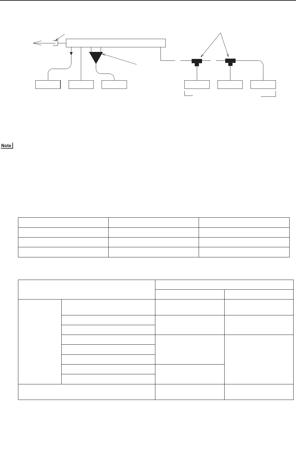
[ II Restrictions ]
- 71 -
HWE09080 GB
(2) Size of the pipe that fits the main BC controller ports
P72 - P240 models
The ports of the BC controller accommodates the pipes on P24-P54 models of indoor units. To connect other types of indoor
units, follow the procedure below.
1) To connect P06-P18 models of indoor units use the reducer that is supplied with the BC controller.
2) To connect the units between the P36 and P96 models of indoor units (or when the total capacity of indoor units is P31
or above), use a junction pipe kit and merge the two nozzles.
3) To connect multiple indoor units to a port (or to a junction pipe)
Maximum total capacity of connected indoor units: P54 or below (in a system with a junction pipe: P96 or below)
Maximum number of connectable indoor units: 3 units
Branch joint: Use CMY-Y102S-G2 (optional accessory).
Refrigerant pipe selection (size of the pipes in sections A and B in the figure above): Select the proper based on the total
capacity of the downstream indoor units, using the table below as a reference.
Unit : mm [inch]
Total capacity of indoor units Liquid pipe Gas pipe
P54 or below ø9.52 [3/8"] ø15.88 [5/8"]
P55 - P72 ø9.52 [3/8"] ø19.05 [3/4"]
P73 - P96 ø9.52 [3/8"] ø22.2 [7/8"]
Unit : mm [inch]
Model Pipe sections
High pressure side (Liquid) Low-pressure side (Gas)
Heat source unit
side
PQRY-P72THMU-A/YHMU-A ø15.88 [5/8"]
(Brazed connection)
ø19.05 [3/4"]
(Brazed connection)
PQRY-P96THMU-A/YHMU-A ø19.05 [3/4"]
(Brazed connection)
ø22.2 [7/8"]
(Brazed connection)
PQRY-P120THMU-A/YHMU-A
PQRY-P144TSHMU-A/YSHMU-A
ø22.2 [7/8"]
(Brazed connection) ø28.58 [1-1/8"]
(Brazed connection)
PQRY-P168TSHMU-A/YSHMU-A
PQRY-P192TSHMU-A/YSHMU-A
PQRY-P216TSHMU-A/YSHMU-A ø28.58 [1-1/8"]
(Brazed connection)
PQRY-P240TSHMU-A/YSHMU-A
Indoor unit side ø9.52 [3/8"]
(Flare connection)
ø15.88 [5/8"]
(Flare connection)
A B
Indoor Indoor Indoor
P18 model or below P24-P54 models P72 or P96 model
*2
Junction pipe kit
(Model name:
CMY-R160-J)
(Optional accessory)
BC controller (main)
To heat
source unit Connection: Brazed connection
*1
Reducer
(Standard supplied parts)
Maximum of 3 units per port
Total capacity of P54 or below
(All units connected to the same port
must be in the same operating mode.)
3*
Indoor Indoor Indoor
Branch joint (Model name:CMY-Y102S-G2)
(Optional accessory)
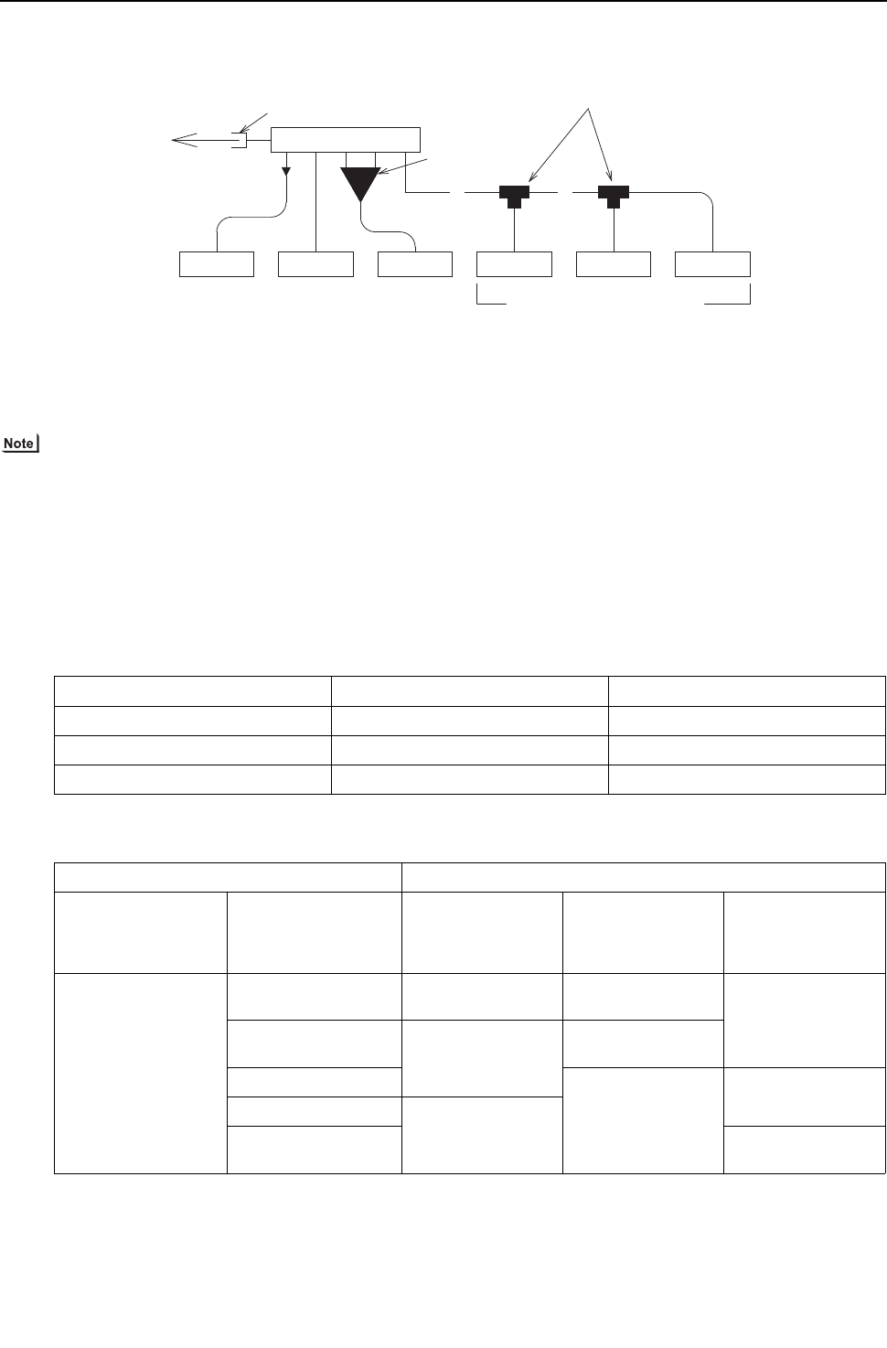
[ II Restrictions ]
- 72 -
HWE09080 GB
(3) Size of the pipe that fits the sub BC controller ports
The ports of the BC controller accommodates the pipes on P24-P54 models of indoor units. To connect other types of indoor
units, follow the procedure below.
1) To connect P06-P18 models of indoor units use the reducer that is supplied with the BC controller.
2) To connect the units between the P36 and P96 models of indoor units (or when the total capacity of indoor units is P31
or above), use a junction pipe kit and merge the two nozzles.
3) To connect multiple indoor units to a port (or to a junction pipe)
Maximum total capacity of connected indoor units: P54 or below (in a system with a junction pipe: P96 or below)
Maximum number of connectable indoor units: 3 units
Branch joint: Use CMY-Y102S-G2 (optional accessory).
Refrigerant pipe selection (size of the pipes in sections A and B in the figure above): Select the proper based on the total
capacity of the downstream indoor units, using the table below as a reference.
Select the proper size pipes for the main unit based on the total capacity of the indoor units that are connected to both sub
BC controllers. Select the proper size pipes for the sub controller side based on the total capacity of the indoor units that are
connected to the sub controller.
Unit : mm [inch]
Total capacity of indoor units Liquid pipe Gas pipe
P54 or below ø9.52 [3/8"] ø15.88 [5/8"]
P55 - P72 ø9.52 [3/8"] ø19.05 [3/4"]
P73 - P96 ø9.52 [3/8"] ø22.2 [7/8"]
Unit : mm [inch]
Operation Pipe sections
High-pressure side
(liquid)
Low-pressure side
(gas) Liquid pipe side
Total capacity of the in-
door units that are con-
nected to the BC
controller
On the BC controller
side P72 model or below ø15.88 [5/8"]
(Brazed connection)
ø19.05 [3/4"]
(Brazed connection) ø9.52 [3/8"]
(Brazed connection)
P73 - P108 ø19.05 [3/4"]
(Brazed connection)
ø22.2 [7/8"]
(Brazed connection)
P109 - P126
ø28.58 [1-1/8"]
(Brazed connection)
ø12.7 [1/2"]
(Brazed connection)
P127 - P144 ø22.2 [7/8"]
(Brazed connection)
P145 - P168 ø15.88 [5/8"]
(Brazed connection)
A B
Indoor Indoor Indoor
P18 model or below P24-P54 models P72 or P96 model
*2
Junction pipe kit
(Model name:
CMY-R160-J)
(Optional accessory)
BC controller (sub)
To Main BC controller
Connection: Brazed connection
*1
Reducer
(Standard supplied parts)
Maximum of 3 units per port
Total capacity of P54 or below
(All units connected to the same port
must be in the same operating mode.)
3*
Indoor Indoor Indoor
Branch joint (Model name:CMY-Y102S-G2)
(Optional accessory)

- 73 -
HWE09080 GB
III
Heat source Unit Components
[1] Heat source Unit Components and Refrigerant Circuit.................................................... 75
[2] Control Box of the Heat source Unit ................................................................................ 78
[3] Heat source Unit Circuit Board ........................................................................................ 81
[4] BC Controller Components .............................................................................................. 88
[5] Control Box of the BC Controller...................................................................................... 91
[6] BC Controller Circuit Board.............................................................................................. 92

- 74 -
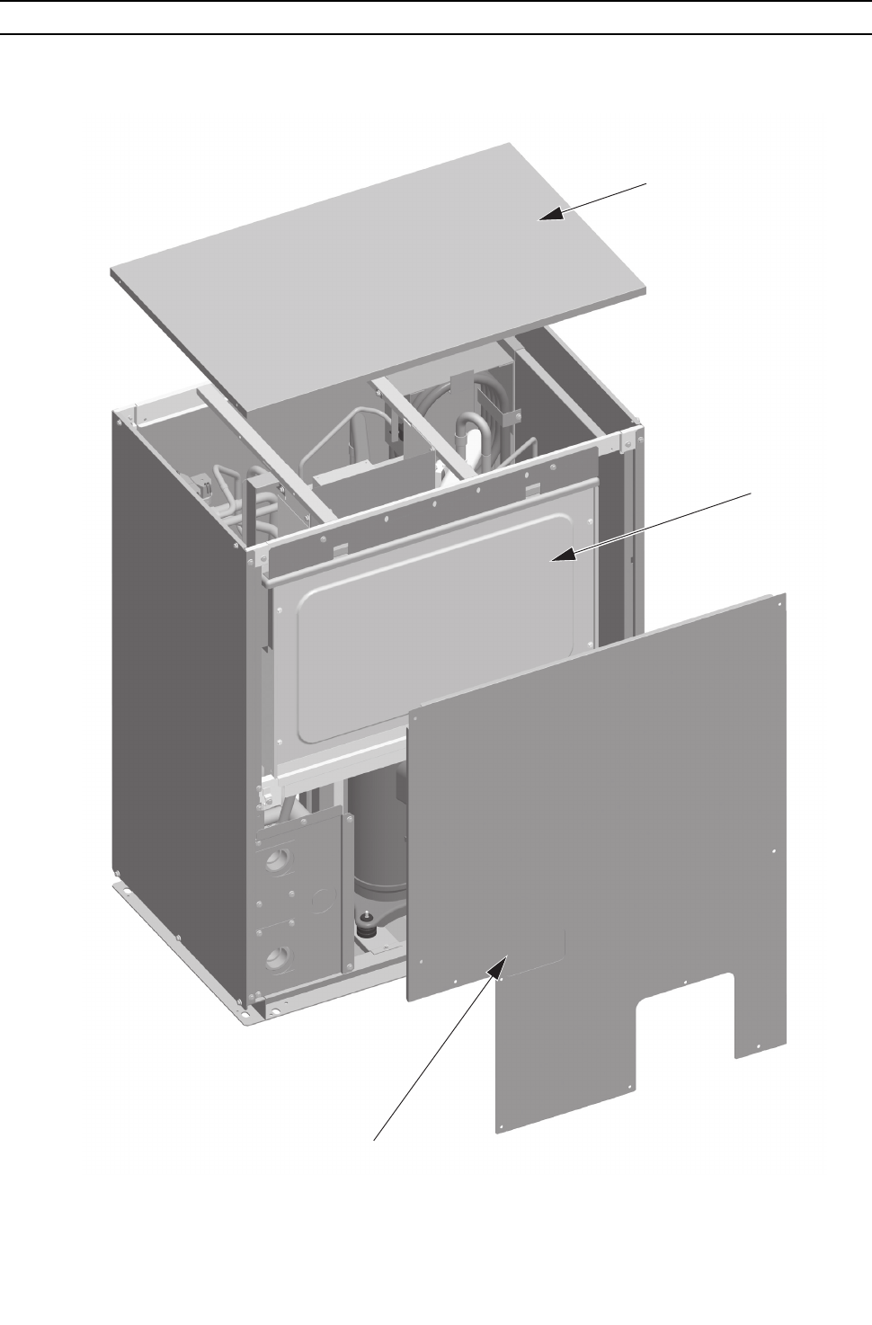
[ III Heat source Unit Components ]
- 75 -
HWE09080 GB
III Heat source Unit Components
[1] Heat source Unit Components and Refrigerant Circuit
1. Front view of a heat source unit
(1) PQHY-P72, 96, 120THMU-A, PQRY-P72, 96, 120THMU-A
PQHY-P72, 96, 120YHMU-A, PQRY-P72, 96, 120YHMU-A
Control box
Top panel
Front panel
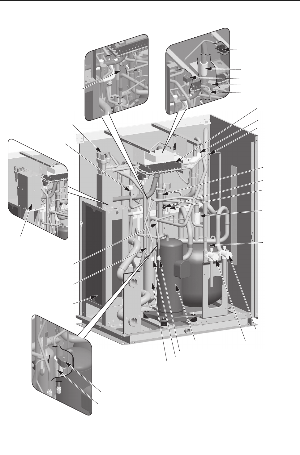
[ III Heat source Unit Components ]
- 76 -
HWE09080 GB
2. Refrigerant circuit
(1) PQHY-P72, 96, 120THMU-A, PQHY-P72, 96, 120YHMU-A
High-pressure
switch(63H1)
High-pressure
sensor(63HS1)
LEVINV
Check valve(CV5a)
4-way valve(21S4a)
Accumulator
(ACC)
Check valve(CV2a)
Compressor(COMP)
Oil separator(O/S)
Check joint (high pressure)(CJ1)
Check joint (low pressure)(CJ2)
Refrigerant service valve
(low pressure)(BV1)
Refrigerant service valve
(high pressure)(BV2)
Solenoid valve block
(SV4a, SV4b, SV4d)
Water heat exchanger
Check valve(CV11)
Check valve(CV6a)
Check valve(CV4a)
Solenoid valve(SV7b)
Transformer Box
(YHMU only)
Check valve(CV3a)
Component cooler
heat exchanger
Solenoid valve(SV1a)
Check valve(CV8)
Solenoid valve(SV7a)
Solenoid valve(SV9)
Low-pressure sensor
(63LS)
Check valve(CV7a)
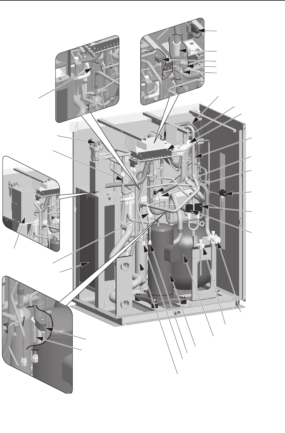
[ III Heat source Unit Components ]
- 77 -
HWE09080 GB
(2) PQRY-P72, 96, 120THMU-A, PQRY-P72, 96, 120YHMU-A
High-pressure
switch(63H1)
High-pressure
sensor(63HS1)
LEVINV
Double pipe(SCC)
4-way valve(21S4a)
Check valve
(CV1a)
Accumulator(ACC)
LEV2a
LEV2b
LEV1
Compressor(COMP)
Oil separator(O/S)
Check joint (high pressure)(CJ1)
Check joint (low pressure)(CJ2)
Refrigerant service valve
(low pressure)(BV1)
Refrigerant service valve
(high pressure)(BV2)
Solenoid valve block
(SV4a, SV4b, SV4d)
Water heat exchanger
Check valve(CV6a)
Check valve(CV4a)
Solenoid valve(SV7b)
Component cooler
heat exchanger
Solenoid valve(SV1)
Check valve(CV8)
Solenoid valve(SV7a)
Solenoid valve(SV9)
Low-pressure sensor
(63LS)
Check valve(CV7a)
Transformer Box
(YHMU only)
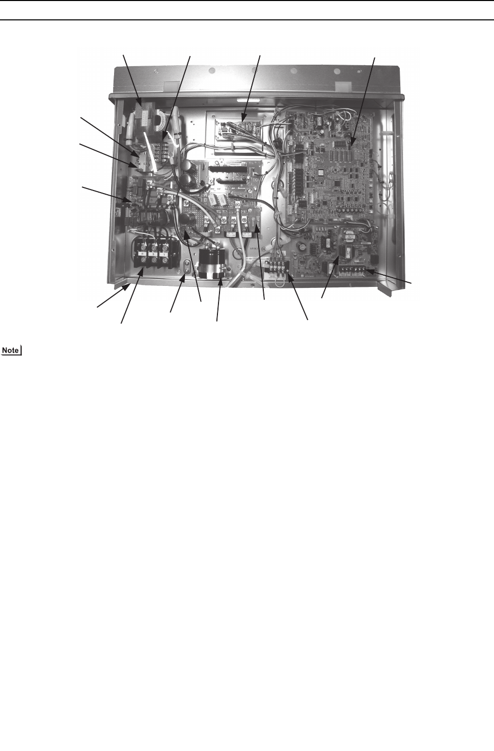
[ III Heat source Unit Components ]
- 78 -
HWE09080 GB
[2] Control Box of the Heat source Unit
(1) PQHY-P72, 96, 120THMU-A, PQRY-P72, 96, 120THMU-A
1) Exercise caution not to damage the bottom and the front panel of the control box. Damage to these parts affect the waterproof
and dust proof properties of the control box and may result in damage to its internal components.
2) Faston terminals have a locking function. Make sure the cable heads are securely locked in place. Press the tab on the ter-
minals to remove them.
DC reactor
(DCL)
Electromagnetic relay
(72C)
Relay board Control board
Inrush current resistor
Note2
Note2
Noise filter
Power supply terminal block
(TB1)
Ground terminal
Smoothing capacitor
(C1)
INV board M-NET board
Terminal block for
transmission line
(TB3,TB7)
Pump interlock terminal block
(TB8)
Note1
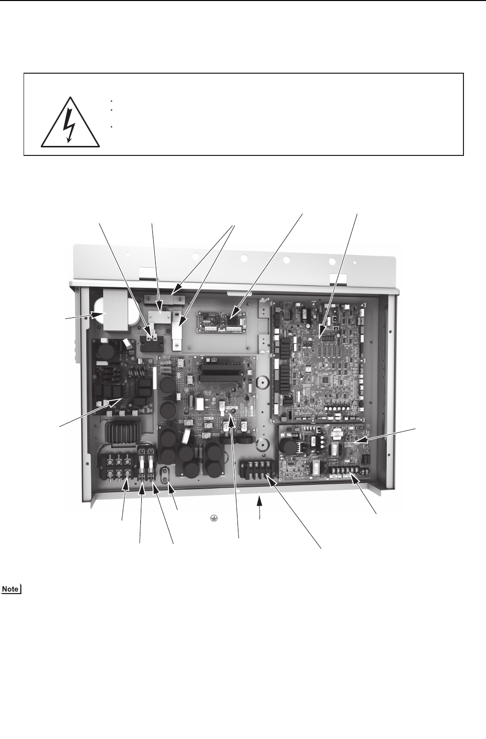
[ III Heat source Unit Components ]
- 79 -
HWE09080 GB
(2) PQHY-P72, 96, 120YHMU-A, PQRY-P72, 96, 120YHMU-A
1) Exercise caution not to damage the bottom and the front panel of the control box. Damage to these parts affect the waterproof
and dust proof properties of the control box and may result in damage to its internal components.
2) Faston terminals have a locking function. Make sure the cable heads are securely locked in place. Press the tab on the ter-
minals to remove them.
<HIGH VOLTAGE WARNING>
Control box houses high-voltage parts.
When opening or closing the front panel of the control box, do not let it come into contact with any of
the internal components.
Before inspecting the inside of the control box, turn off the power, keep the unit off for at least 10 minutes,
and confirm that the voltage between FT-P and FT-N on INV Board has dropped to DC20V or less.
(It takes about 10 minutes to discharge electricity after the power supply is turned off.)
Control boardRelay board
M-NET board
Terminal block for
transmission line
(TB3, TB7)
INV board
Pump interlock terminal block
(TB8)
Note1
Fuse
(F4) Fuse
(F5)
Ground
terminal
Power supply terminal block
L1,L2,L3
(TB1)
Noise filter
DC reactor
(DCL)
Electromagnetic relay
(72C)
Capacitor
(C100)
Inrush current resistor
(R1,R5) Note2
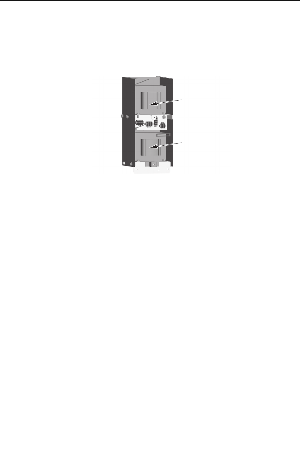
[ III Heat source Unit Components ]
- 80 -
HWE09080 GB
1. Transformer Box
(1) PQHY-P72, 96, 120YHMU-A, PQRY-P72, 96, 120YHMU-A
Transformer
(T03)
Transformer
(T02)
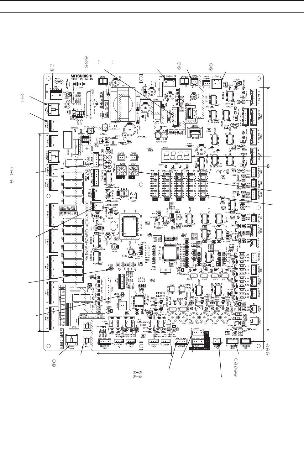
[ III Heat source Unit Components ]
- 81 -
HWE09080 GB
[3] Heat source Unit Circuit Board
1. Heat source unit control board
CN332
Output 18VDC
GND
LED2
Lit during normal
CPU operation
Serial communication signal input
GND
INV board
Output 17VDC
CN801
Pressure switch
connection
CN4
GND
Serial communication signal output
LEV
driving output
LED1
Service LED
SWU1,2
Address switch
SW1-5
Dip
switch
Sensor
input
CNVCC2
Output 12VDC
Output 5VDC
GND
CNIT
Output 12VDC
GND
Output 5VDC
Power supply detection input
Power supply ON/OFF signal output
CNS2
Transmission line input/output
for centralized control system (30VDC)
CN41
Power supply for
centralized control OFF
CN40
Power supply for
centralized control ON
CN102
Indoor-heat source transmission line input/output (30VDC)
Power supply input for centralized control system (30VDC)
External signal input (contact input)
F01
Fuse
250V AC/3.15A
CNAC
L1
L2
Actuator
driving output
Output 12VDC
Compressor
ON/OFF output
Error output
CN51
CNAC2
L1
L2
CNDC
Bus voltage input
P
N
CN2
CN72
72C driving output
(YHMU)
CN505
72C driving output
(THMU)
LED3
Lit when powered
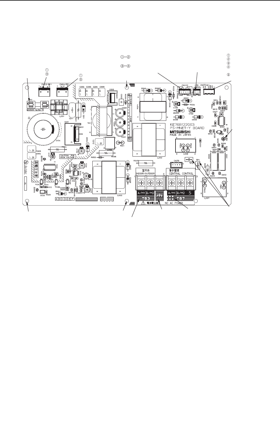
[ III Heat source Unit Components ]
- 82 -
HWE09080 GB
2. M-NET board
Power supply output for centralized
control system (30VDC)
Indoor-heat source transmission line
input/output (30VDC)
CN102 CNS2
Transmission line
input/output for
centralized control
system (30VDC)
CNIT
Input 12VDC
GND
Input 5VDC
Power supply
detection output
Power supply
ON/OFF signal input
LED1
Power supply for
indoor
transmission line
TP1,2
Check pins for
indoor-heat source
transmission line
TB7
Terminal block for
transmission line for
centralized control
TB3
Indoor-heat source transmission block
Ground terminal for
transmission line
Grounding
Grounding
CN04
Bus voltage input
(YHMU only)
Bus voltage output
(THMU only)
P
N
CN03(THMU only)
Bus voltage input
P
N
(THMU only)
F01
250V
3.15A Grounding
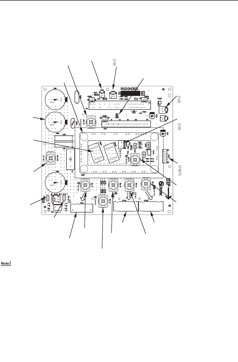
[ III Heat source Unit Components ]
- 83 -
HWE09080 GB
3. INV board
(1) PQHY-P72, 96, 120THMU-A, PQRY-P72, 96, 120THMU-A
Faston terminals have a locking function. Make sure the cable heads are securely locked in place. Press the tab on the ter-
minals to remove them.
IGBT
(Rear)
SC-P1
Rectifier diode output (P)
CN6
Open: No-load operation setting
Short-circuited: Normal setting
CN5V
GND
Output 5VDC
LED1
Lit: Inverter in normal operation
Blink: Inverter error
CN4
GND(Control board)
Serial communication signal output
CNDC
Bus voltage output
P
N
CN2
S
erial communication signal output
GND
Input 17VDC
SC-V
Inverter output(V)
SC-W
Inverter output(W)
CT22
Current sensor
(W)
SC-U
Inverter output(U)
CT12
Current sensor
(U)
SC-R
Input(L1)
SC-S
Input(L2)
SC-T
Input(L3)
CT3
Current sensor(
L3)
TB-N(Note)
Bus voltage output
(N)
TB-P(Note)
Bus voltage output(P
)
SC-P2
Bus voltage Input(
P)
RSH1,2
Overcurrent detection
resistor
C30,31,32
Smoothing capacitor
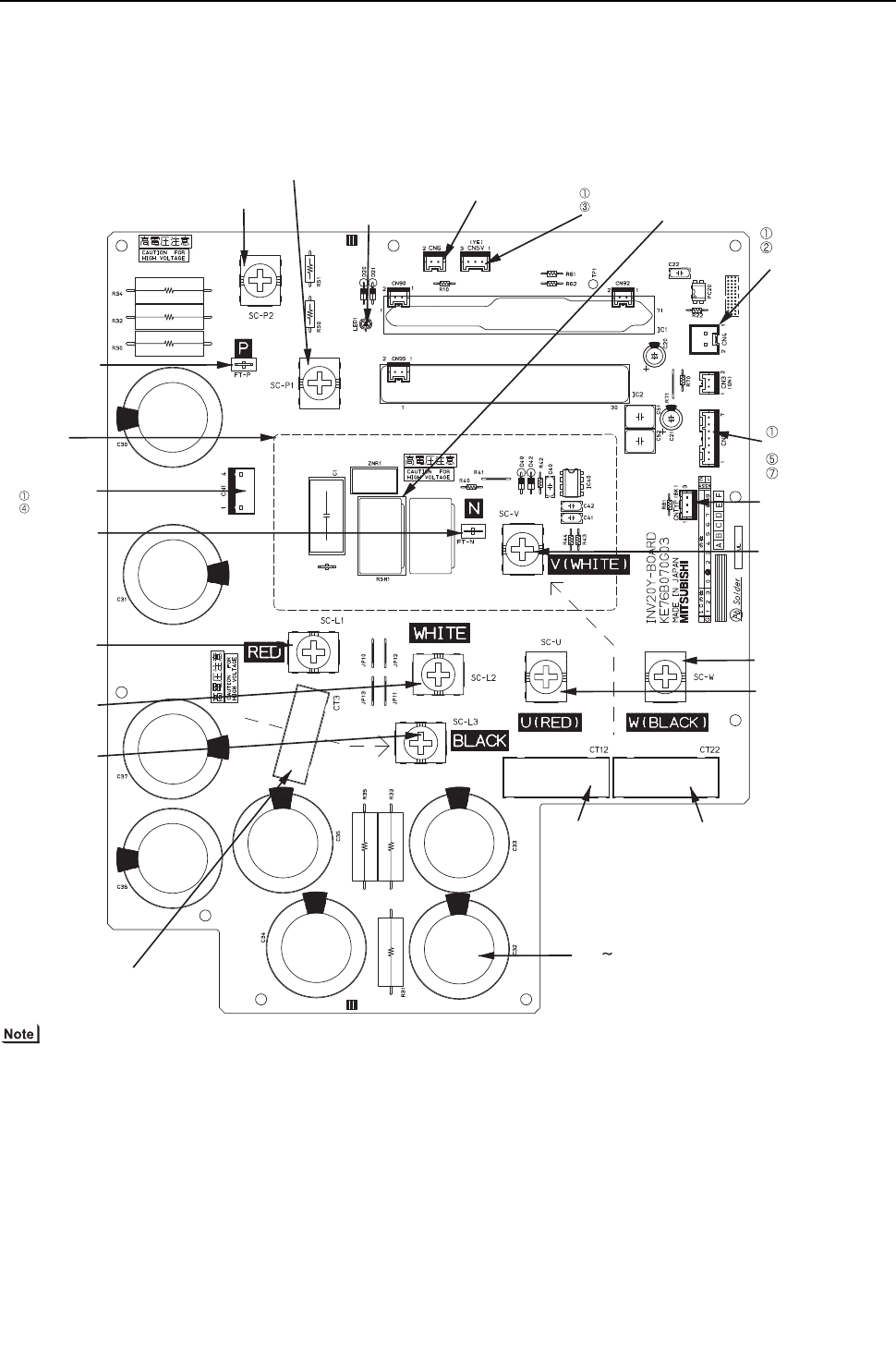
[ III Heat source Unit Components ]
- 84 -
HWE09080 GB
(2) PQHY-P72, 96, 120YHMU-A, PQRY-P72, 96, 120YHMU-A
1) Before inspecting the inside of the control box, turn off the power, keep the unit off for at least 10 minutes, and confirm that
the voltage between FT-P and FT-N on INV Board has dropped to DC20V or less.
(It takes about 10 minutes to discharge electricity after the power supply is turned off.)
SC-L1
Input(L1)
SC-L2
Input(L2)
SC-L3
Input(L3)
IGBT
(Rear)
Bus voltage check
terminal (P)
Note
Bus voltage check
terminal (N)
Note 1
SC-P2
Bus voltage Input(P)
SC-P1
Rectifier diode output (P)
LED1
Lit: Inverter in normal operation
Blink: Inverter error
CN6
Open: No-load operation setting
Short-circuited: Normal setting CN5V
GND
5VDC output
RSH1
Overcurrent detection
resistor
CN4
GND(Control board)
Serial communication
signal output
CN2
S
erial communication
signal output
GND
17VDC input
SC-V
Inverter output(V)
CNTYP Inverter
board type
SC-W
Inverter output(W)
SC-U
Inverter output(U)
CT22
Current sensor(W)
CT12
Current sensor(U)
C30 C37
Smoothing capacitor
CN1
Bus voltage output
N
P
CT3
Current sensor(L3)
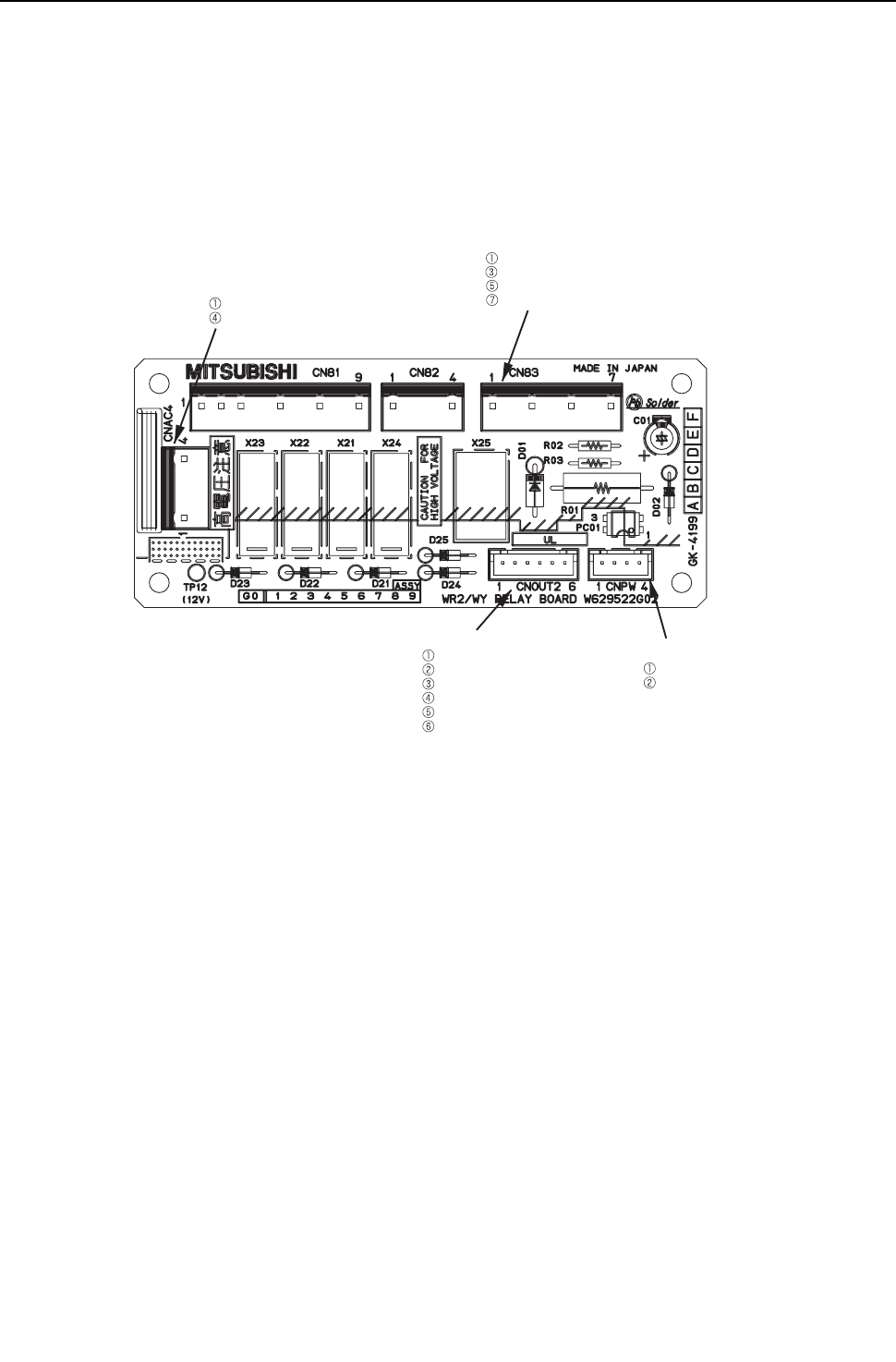
[ III Heat source Unit Components ]
- 85 -
HWE09080 GB
4. Relay board
CNOUT2
12 VDC input
Relay driving signal input (X21)
Relay driving signal input (X22)
Relay driving signal input (X23)
Relay driving signal input (X24)
Relay driving signal input (X25)
CNAC4
L1 input
L2
CN83
Pump interlock signal output
Pump interlock signal output
Pump interlock signal input
Pump interlock signal input
CNPW
Pump interlock signal output
Pump interlock signal output
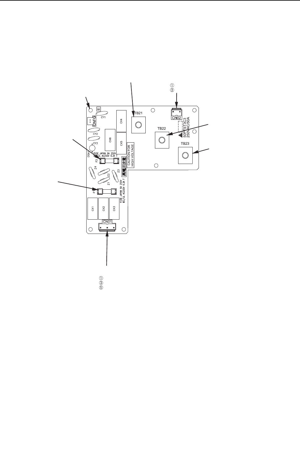
[ III Heat source Unit Components ]
- 86 -
HWE09080 GB
5. Noise Filter
(1) PQHY-P72, 96, 120THMU-A, PQRY-P72, 96, 120THMU-A
Grounding
TB21
Input/output(L1)CN02
Output
L1
L2
TB22
Input/output(L2)
TB23
Input/output(L3)
CN01
Input
L3
L2
L1
F1
Fuse
250VAC 6.3A
F2
Fuse
250VAC 6.3A
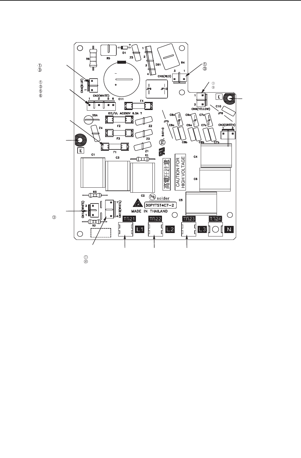
[ III Heat source Unit Components ]
- 87 -
HWE09080 GB
(2) PQHY-P72, 96, 120YHMU-A, PQRY-P72, 96, 120YHMU-A
CN4
Output
(Rectified L2-L3 current)
P
N
CN5
Output
(Rectified L2-L3 current)
P
N
TB21
Input/output(L1)
TB22
Input/output(L2)
TB23
Input/output(L3)
CN1B
Input
L3
L2
CN1A
Input
L1
Grounding
F1,F2,F3,F4
Fuse
250VAC 6.3A
CN6
Input
L2
L3
Grounding
CN2
Surge absorber circuit
Surge absorber circuit
Short circuit
Short circuit
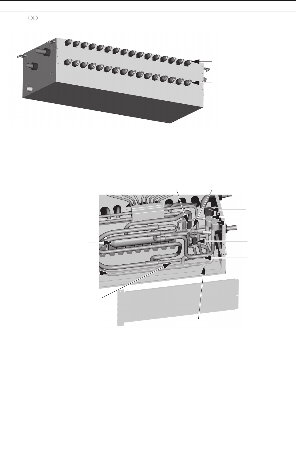
[ III Heat source Unit Components ]
- 88 -
HWE09080 GB
[4] BC Controller Components
1. CMB-P NU-G, GA
(1) Front
(2) Rear view <G type>
Liquid pipe (Indoor unit side)
Gas pipe (Indoor unit side)
TH12
TH15
TH16
TH11
SVM1
LEV1
LEV3
PS1
PS3
Tube in tube heat exchanger
Gas/Liquid separator
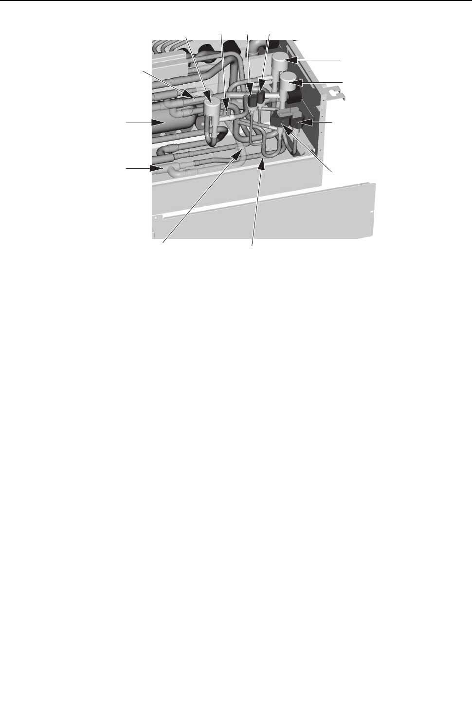
[ III Heat source Unit Components ]
- 89 -
HWE09080 GB
(3) Rear view <GA type>
TH12 TH15
TH16
TH11
SVM2
SVM1
LEV1
LEV3
LEV2 PS1
PS3
Tube in tube heat exchanger
Gas/Liquid separator
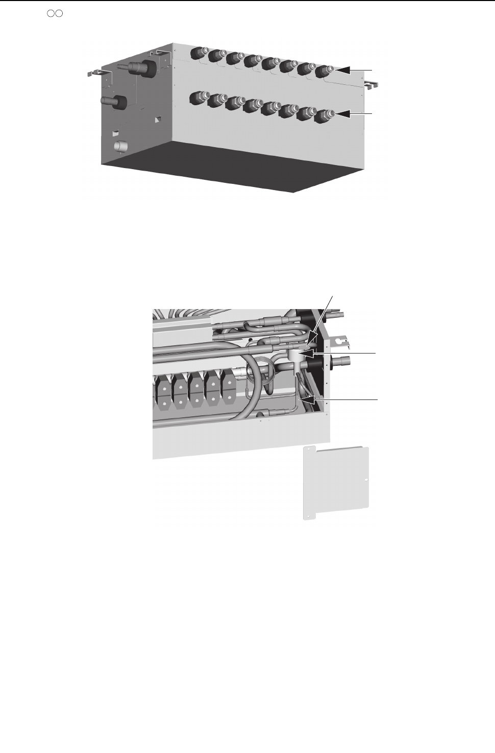
[ III Heat source Unit Components ]
- 90 -
HWE09080 GB
2. CMB-P NU-GB, HB
(1) Front
(2) Rear view
Liquid pipe (Indoor unit side)
Gas pipe (Indoor unit side)
TH15
TH12
LEV3
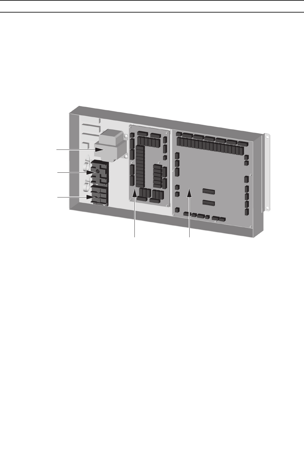
[ III Heat source Unit Components ]
- 91 -
HWE09080 GB
[5] Control Box of the BC Controller
1. CMB-P1016NU-G, GA
Relay board
Transformer
Terminal block for
transmission line
BC controller board
Terminal block for
power supply
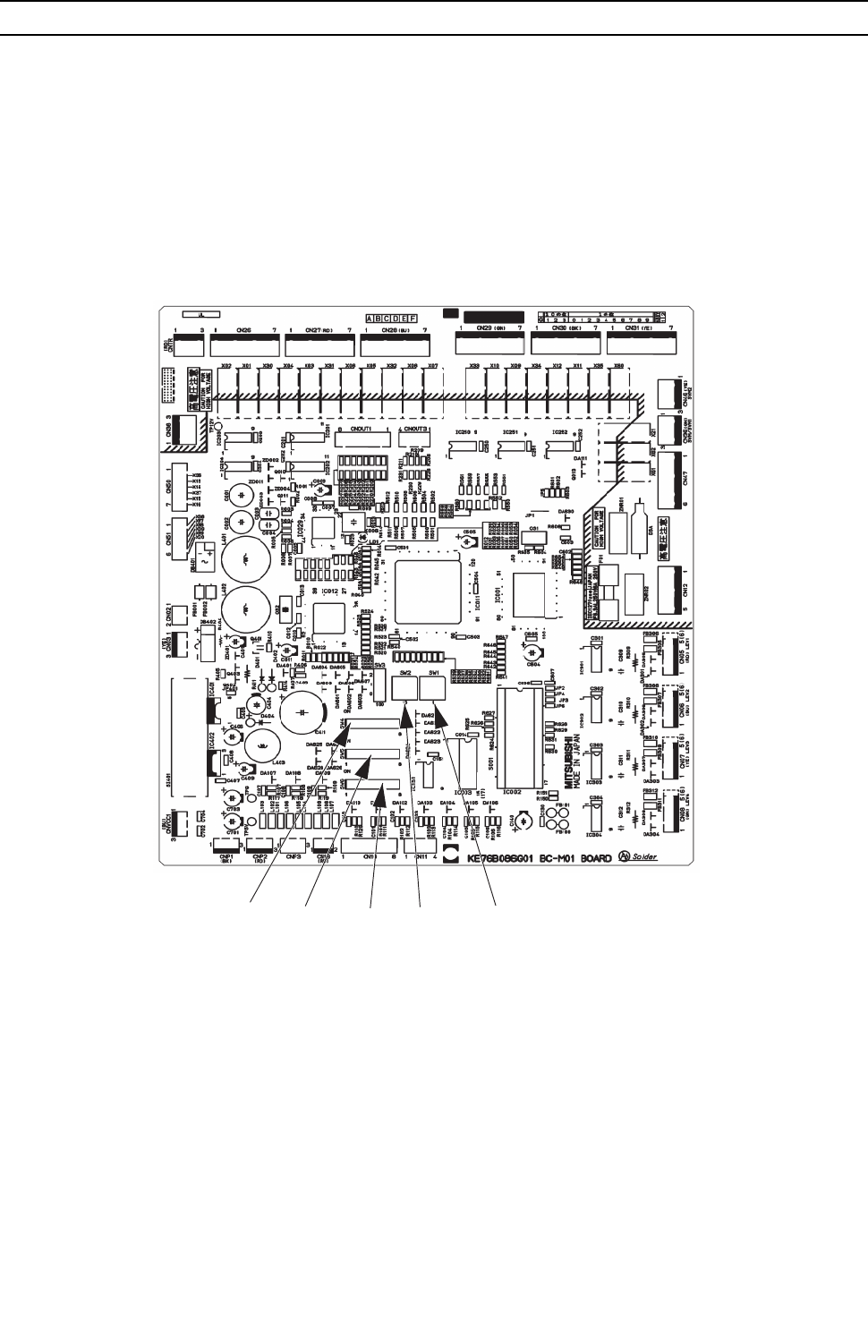
[ III Heat source Unit Components ]
- 92 -
HWE09080 GB
[6] BC Controller Circuit Board
1. BC controller circuit board (BC board)
SW1SW2
SW5 SW6
SW4
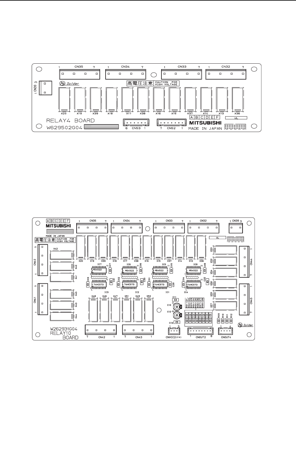
[ III Heat source Unit Components ]
- 93 -
HWE09080 GB
2. RELAY BOARD (RELAY 4 board)
3. RELAY BOARD (RELAY 10 board)

- 94 -
[ III Heat source Unit Components ]
GBHWE09080

- 95 -
HWE09080 GB
IV
Remote Controller
[1] Functions and Specifications of MA and ME Remote Controllers ................................... 97
[2] Group Settings and Interlock Settings via the ME Remote Controller ............................. 98
[3] Interlock Settings via the MA Remote Controller ........................................................... 102
[4] Using the built-in Temperature Sensor on the Remote Controller ................................. 103

- 96 -
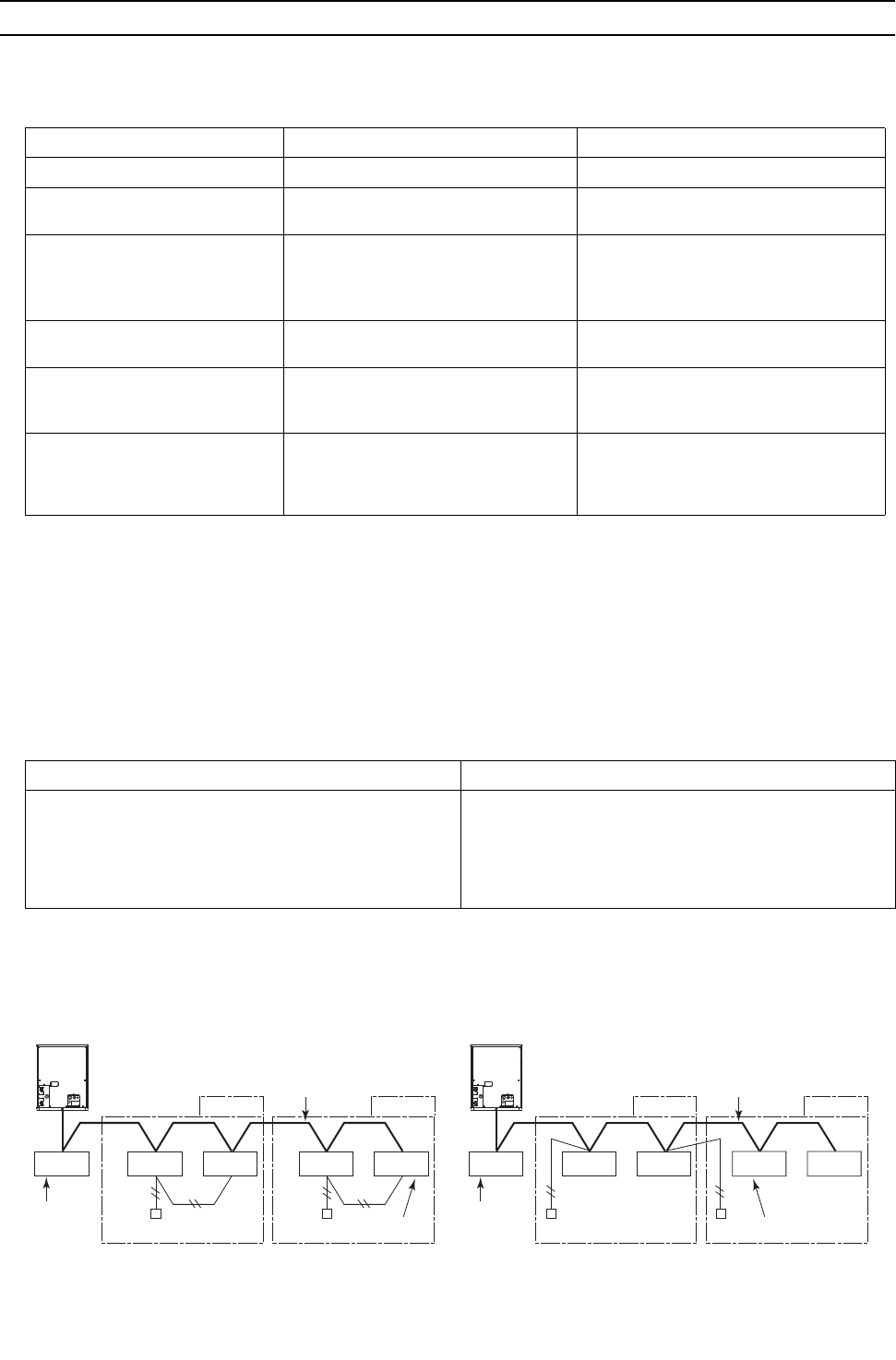
[ IV Remote Controller ]
- 97 -
HWE09080 GB
IV Remote Controller
[1] Functions and Specifications of MA and ME Remote Controllers
There are two types of remote controllers: ME remote controller, which is connected on the indoor-heat source transmis-
sion line, and MA remote controller, which is connected to each indoor unit.
1. Comparison of functions and specifications between MA and ME remote controllers
2. Remote controller selection criteria
MA remote controller and ME remote controller have different functions and characteristics. Choose the one that better suits
the requirements of a given system. Use the following criteria as a reference.
Functions/specifications MA remote controller*1*2
*1. MA remote controller refers to MA remote controller (PAR-20MAA, PAR-21MAA), MA simple remote controller, and wire-
less remote controller.
*2. Either the MA remote controller or the ME remote controller can be connected when a group operation of units in a sys-
tem with multiple heat source units is conducted or when a system controller is connected.
ME remote controller*2*3
*3. ME remote controller refers to ME remote controller and ME simple remote controller.
Remote controller address settings Not required Required
Indoor-heat source unit address
settings
Not required (required only by a system
with one heat source unit)*4
*4. Depending on the system configuration, some systems with one heat source unit may require address settings.
Required
Wiring method Non-polarized 2-core cable
To perform a group operation, daisy-
chain the indoor units using non-polar-
ized 2-core cables.
Non-polarized 2-core cable
Remote controller connection Connectable to any indoor unit in the
group
Connectable anywhere on the indoor-heat
source transmission line
Interlock with the ventilation unit Each indoor unit can individually be in-
terlocked with a ventilation unit. (Set up
via remote controller in the group.)
Each indoor unit can individually be inter-
locked with a ventilation unit. (Set up via
remote controller.)
Changes to be made upon group-
ing change
MA remote controller wiring between in-
door units requires rewiring.
Either the indoor unit address and remote
controller address must both be changed,
or the registration information must be
changed via MELANS.
MA remote controller*1*2 ME remote controller*1*2
There is little likelihood of system expansion and group-
ing changes.
Grouping (floor plan) has been set at the time of instal-
lation.
There is a likelihood of centralized installation of remote
controllers, system expansion, and grouping changes.
Grouping (floor plan) has not been set at the time of in-
stallation.
To connect the remote controller directly to the OA pro-
cessing unit.
*1. ME remote controller and MA remote controller cannot both be connected to the same group of indoor units.
*2. A system controller must be connected to a system to which both MA remote controller and ME remote controller are con-
nected.
<System with MA remote controller> <System with ME remote controllers>
MA remote controller
Heat source unit
Indoor unit
BC
controller
M-NET transmission line
(indoor-heat source transmission line)
groupgroup
ME remote controller
Heat source unit
Indoor unit
BC
controller
M-NET transmission line
(indoor-heat source transmission line)
groupgroup
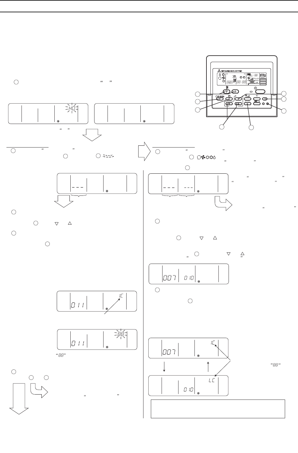
[ IV Remote Controller ]
- 98 -
HWE09080 GB
[2] Group Settings and Interlock Settings via the ME Remote Controller
1. Group settings/interlock settings
<Deletion error>
[Normal display]
(B) Interlock Settings (A) Group Settings
Indoor unit address display window Indoor unit
address
display window
Interlocked unit
address
display window
Make the following settings to perform a group operation of units that are connected to different heat source units or to manually set up the
indoor-heat source unit address.
(A) Group settings...........Registration of the indoor units to be controlled with the remote controller,
and search and deletion of registered information.
(B) Interlock settings........Registration of LOSSNAY units to be interlocked with the indoor units,
and search and deletion of registered information
[Operation Procedures]
(1) Address settings
Register the indoor unit to be controlled with the remote controller.
Bring up either the blinking display of HO by turning on the unit or the
normal display by pressing the ON/OFF button.
The display window must look like one of the two figures below to proceed to the
next step.
1
2
Bring up the Group Setting window.
-Press and hold buttons [FILTER] and [ ]
simultaneously for 2 seconds to bring up the display as
shown below.
3
A
C
D
B
Select the unit address.
- Select the address of the indoor unit to be registered by pressing
button [TEMP. ( ) or ( )] to advance or go back
through the addresses.
Register the indoor unit whose address appears on the
display.
- Press button [TEST] to register the indoor unit address
whose address appears on the display.
- If registration is successfully completed, unit type will appear
on the display as shown in the figure below.
- If the selected address does not have a corresponding indoor
unit, an error message will appear on the display. Check the
address, and try again.
5
<Successful completion of registration>
Unit type (Indoor unit in this case)
blinks to indicate a registration error.
(Indicates that selected address does not have a
corresponding unit.)
4
To register the addresses for multiple indoor units, repeat
steps and above.
3 4
To search for an address,
go to section (2) Address Search.
To next page.
To search for an address,
go to section (2) Address Search.
Bring up the Interlock Setting window.
-Press button [ ] to bring up the following display.
Press again to go back to the Group Setting window as shown
under step .
6
G
2
Both the indoor unit address and
interlocked unit address will be
displayed together.
Bring up the address of the indoor unit and the address of the
LOSSNAY to be interlocked on the display.
- Select the address of the indoor unit to be registered by pressing
button [TEMP. ( ) or ( )] to advance or go back through
the addresses.
- Select the address of the LOSSNAY unit to be interlocked by
pressing button [TIMER SET ( ) or ( )] to advance or go back
through the interlocked unit addresses.
7
8
C
H
Make the settings to interlock LOSSNAY units with indoor
units.
- Press button [TEST] while both the indoor unit address and
the address of the LOSSNAY units to be interlocked
are displayed to enter the interlock setting.
- Interlock setting can also be made by bringing up the
LOSSNAY address in the indoor unit address display
window and the indoor unit address in the interlocked unit
address display window.
D
(Displayed alternately)
If registration is successfully
completed, the two displays as
shown on the left will appear
alternately.
If the registration fails,
will blink on the display.
(Indicates that the selected
address does not have a
corresponding unit.)
NOTE : Interlock all the indoor units in the group with the
LOSSNAY units; otherwise, the LOSSNAY units will
not operate.
[Blinking display of HO ]
?
A
F
D
B
H
G
C
E
PAR-F27MEA
ON/OFF
CENTRALLY CONTROLLED
DAILY
AUTO OFF
REMAINDER
CLOCK
ON OFF
˚ C
CHECK MODE
FILTER
TEST RUN
LIMIT TEMP.
˚ C
1Hr.
NOT AVAILABLE
STAND BY
DEFROST
FILTER
CHECK TEST
TEMP.
TIMER SET
CLOCK → ON → OFF
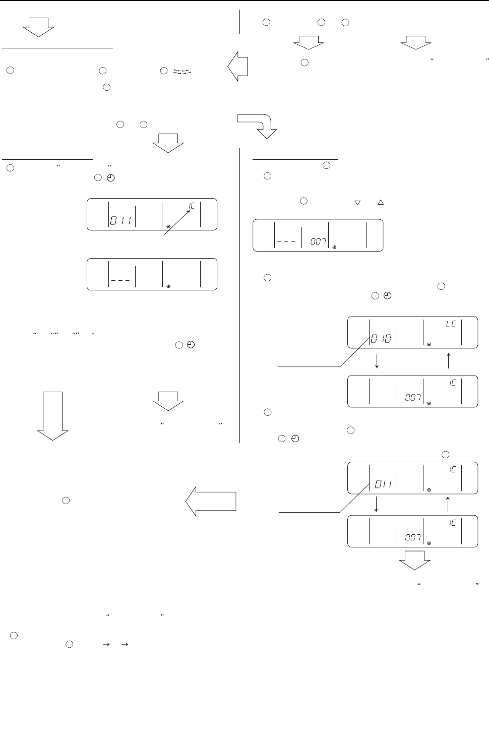
[ IV Remote Controller ]
- 99 -
HWE09080 GB
<Entry found>
<No entries found>
(C) To return to the normal display
When all the group settings and interlock settings are made, take the
following step to go back to the normal display.
Press and hold buttons [FILTER] and [ ]
simultaneously for 2 seconds to go back to the
window as shown in step .
(2) Address search
To search for the address of indoor units that have been entered into
the remote controller, follow steps and .
(A) To search group settings
Unit type
(Indoor unit in this case)
- When only one unit address is registered, the same address
will remain on the display regardless of how many times the
button is pressed.
- When the address of multiple units are registered
(i.e. 011, 012, 013 ), they will be displayed one at a time in
an ascending order with each pressing of button [ ] .
To delete an address, go to
section (3) Address Deletion.
To go back to the normal display,
follow step .
(Displayed alternately)
To delete an address,
go to section (3) Address Deletion .
Bring up the address of another registered unit on the
display.
- After completing step , a subsequent pressing of button
[ ] will bring up the address of another registered
unit.
(The display method is the same as the one in step .)
Address of an interlocked
LOSSNAY unit
Address of another
interlocked unit
Bring up on the display the address of the LOSSNAY unit
that was interlocked with the indoor unit in step .
- With each pressing of button [ ], the address of the
LOSSNAY and indoor unit that is interlocked with it will be
displayed alternately.
LOSSNAY can be searched in the same manner by bringing up
the LOSSNAY address in the Interlocked unit address display window.
(B) Interlock setting search
After performing step , proceed as follows:
Bring up the address of the indoor unit to be searched on
the display.
- Select the address of the indoor unit to be searched by pressing
button [TIMER SET ( ) or ( )] to advance or go back
through the interlocked addresses.
Repeat steps and in the previous page to interlock
all the indoor units in a group with the LOSSNAY unit.
7
8
To go back to the normal display,
follow step .
To search for an address,
go to section (2) Address Search.
(3) Address deletion
The addresses of the indoor units that have been entered into the remote controller can be deleted by deleting the group settings.
The interlock settings between units can be deleted by deleting the interlock settings.
Follow the steps in section (2) Address Search to find the address to be deleted and perform deletion with the address being displayed in the
display window. To delete an address, the address must first be bought up on the display.
Delete the registered indoor unit address or the interlock setting between units.
- Press button ? [CLOCK ON OFF] twice while either the indoor unit address or the address of the interlocked unit is displayed on the
display to delete the interlock setting.
(Displayed alternately)
10
A
B
1
Bring up the Group Setting window.
- Each pressing of button [ ] will bring up the address of a
registered indoor unit and its unit type on the display.
11
E
1 2
E
10
E
13
13
13
12
14
12
6
E
H
9
10
F
15
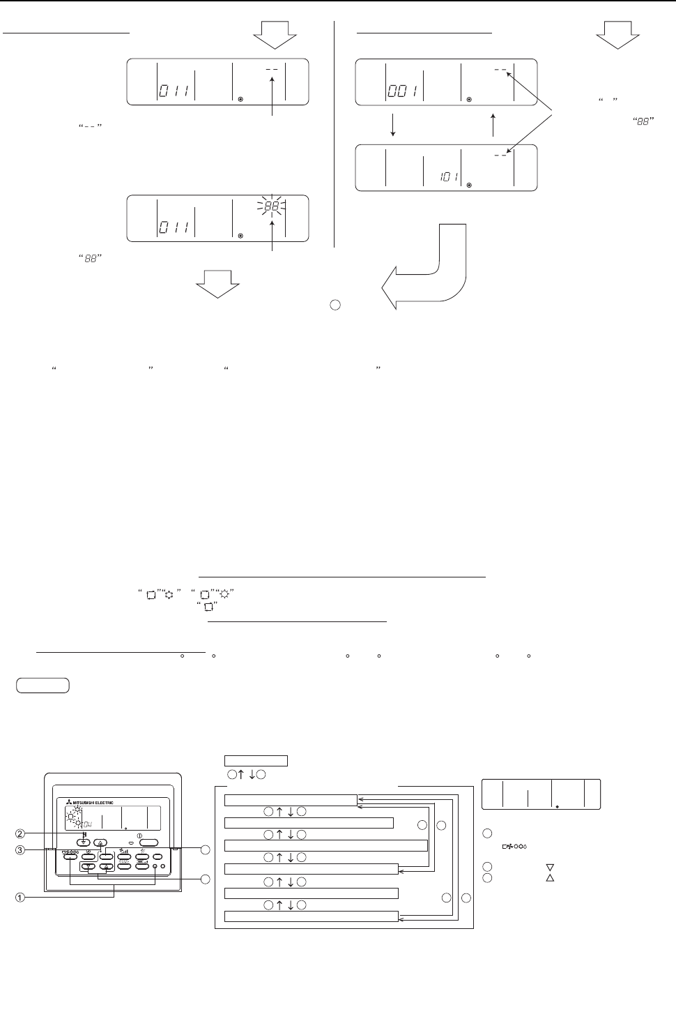
[ IV Remote Controller ]
- 100 -
HWE09080 GB
2. Remote controller function selection via the ME remote controller
(A) To delete group settings (B) To delete interlock settings
<Successful completion of deletion>
will be displayed in the room temperature display window.
- If a transmission error occurs, the selected setting will not be
deleted, and the display will appear as shown below.
In this case, repeat the steps above.
(Displayed alternately)
<Deletion error>
will be displayed in the room temperature display window.
(4) Making (A) Group settings and (B) Interlock settings of a group from any arbitrary remote controller
(A) Group settings and (B) Interlock settings of a group can be made from any arbitrary remote controller.
Refer to (B) Interlock Settings under section 1 Group Settings/Interlock Settings for operation procedures.
Set the address as shown below.
(A) To make group settings
Interlocked unit address display window...Remote controller address
Indoor unit address display window...........The address of the indoor unit to be controlled with the remote controller
(B) To make interlock settings
Interlocked unit address display window...LOSSNAY address
Indoor unit address display window..........The address of the indoor unit to be interlocked with the LOSSNAY
If deletion is successfully
completed, will appear in
the unit type display window.
If the deletion fails, will
appear in the unit type display
window. In this case, repeat the
steps above.
- -
To go back to the normal display, follow step .
10
In the remote controller function selection mode, the settings for four types of functions can be made or changed as necessary.
4) Narrowed preset temperature range mode
The default temperature ranges are 19 C to 30 C in the cooling/dry mode and 17 C to 28 C in the heating mode and 19 C to 28 C in the auto mode.
By changing these ranges (raising the lower limit for the cooling/dry mode and lowering the upper limit for the heating mode), energy can be saved.
When making the temperature range setting on the simultaneous cooling/heating type units that supports the automatic operation mode to save on
energy consumption, enable the Skip-Auto-Mode setting to make the automatic operation mode unselectable. If the automatic operation mode is
selected, the energy-saving function may not work properly.
When connected to the air conditioning units that do not support the automatic operation mode, the setting for the Skip-Auto-Mode, restricted preset
temperature range mode (AUTO), and operation mode display selection mode are invalid. If an attempt is made to change the preset temperature range,
“LIMIT TEMP.” appears on the display.
NOTE
[Normal display]
4
5
PAR-F27MEA
ON/OFF
FILTER
CHECK TEST
TEMP.
TIMER SET
CLOCKONOFF
1
3
2
: Press and hold the [CHECK] and
[ ] buttons simultaneously
for two seconds.
: [SET TEMP.
( ) ]
button
: [SET TEMP.
( ) ]
button
3) Room temperature display selection mode (Display or non-display of room temperature)
Although the suction temperature is normally displayed on the remote controller, the setting can be changed so that it will not appear on the
remote controller.
2) Operation mode display selection mode (Display or non-display of COOL/HEAT during automatic operation mode)
When the automatic operation mode is selected, the indoor unit will automatically perform a cooling or heating operation based on the room
temperature. In this case, or will appear on the remote controller display.
This setting can be changed so that only will appear on the display.
1) Skip-Auto-Mode setting
The automatic operation mode that is supported by some simultaneous cooling/heating type units can be made unselectable via the ME remote
controller.
[Function selection mode sequence on the remote controller]
Normal display
1 1
3
3
3
2
2
2
3
2
3
2
3
2
3
2
Skip-Auto-Mode setting
*1 *1
*2
*2
Temperature range setting mode (AUTO)
Room temperature display selection mode *1 : Skip-Auto-Mode is enabled
*2 : Skip-Auto-Mode is disabled
Operation mode display selection mode (Display or non-display of the automatic mode)
Restricted preset temperature range mode (Heating)
Restricted preset temperature range mode (Cooling)
Remote controller function selection mode
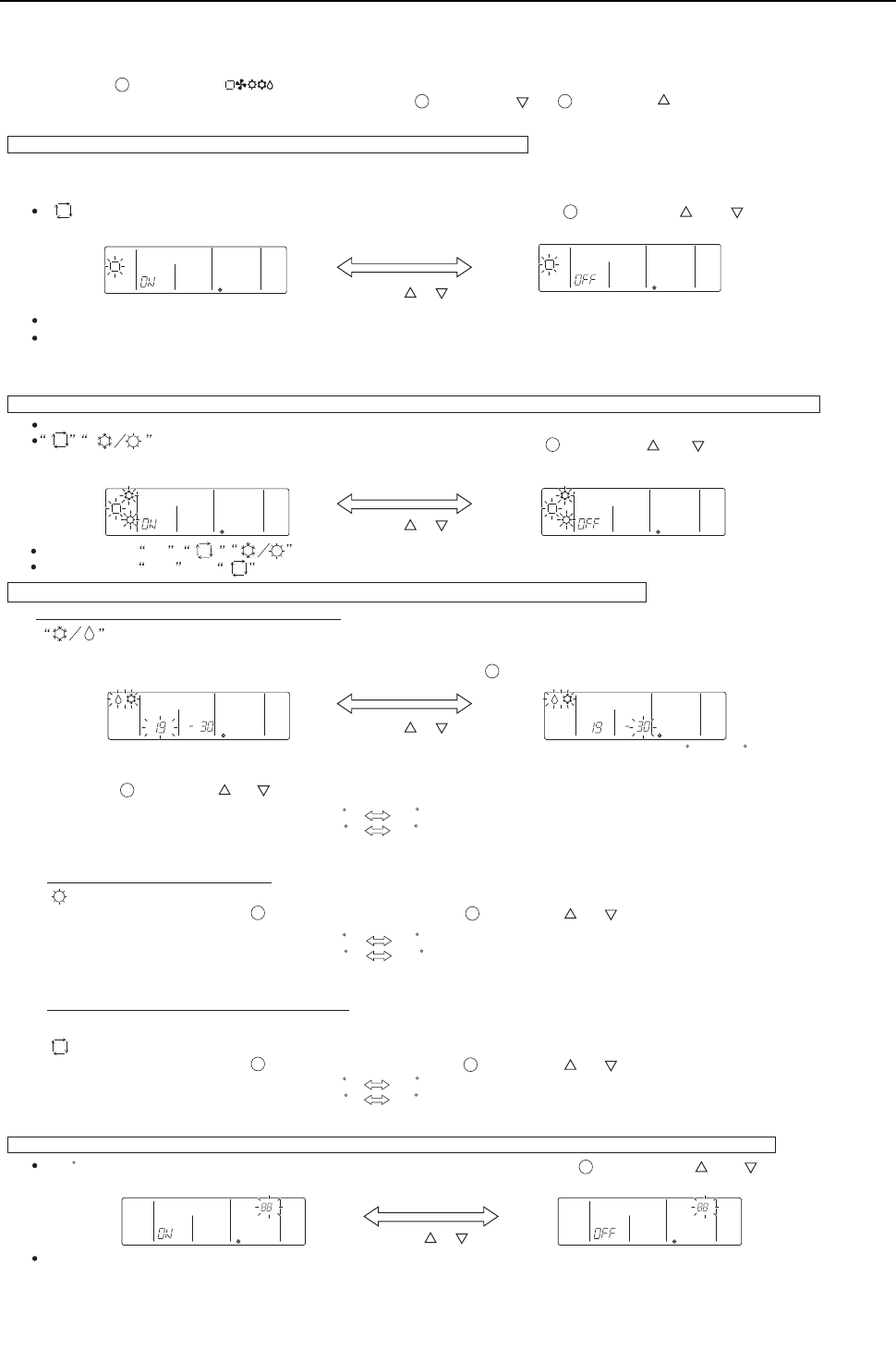
[ IV Remote Controller ]
- 101 -
HWE09080 GB
[Lower limit temperature]: Appears in the preset temperature display window [Upper limit temperature: Appears in the time display window
[Settable range for the lower limit temperature] : 19 C
30 C (Settable up to the upper limit temperature that is shown on the display)
[Settable range for the upper limit temperature] : 30 C 19 C (Settable up to the lower limit temperature that is shown on the display)
[Settable range for the lower limit temperature] : 17 C
28 C (Settable up to the upper limit temperature that is shown on the display)
[Settable range for the upper limit temperature] : 28 C 17 C
(Settable up to the lower limit temperature that is shown on the display)
[Settable range for the lower limit temperature] : 19 C
28 C (Settable up to the upper limit temperature that is shown on the display)
[Settable range for the upper limit temperature] : 28 C 19 C
(Settable up to the lower limit temperature that is shown on the display)
will light up in the display window, and the temperature range for the cooling/dry mode will appear on the display.
[Operation Procedures]
1. Press the [ON/OFF] button on the remote controller to bring the unit to a stop. The display will appear as shown in the previous page (Normal
display).
2. Press buttons [CHECK] and [ ] simultaneously for 2 seconds to go into the “Skip-Auto-Mode setting.”
under the remote controller function selection mode. Press button [SET TEMP. ( )] or [SET TEMP. ( )] to go into the other four modes
under the remote controller function selection mode.
1
2 3
Skip-Auto-Mode setting (Making the automatic operation mode unselectable)
“ ” blinks and either “ON” or “OFF” lights up on the controller. Pressing the [TIMER SET ( ) or ( )] button switches
between “ON” and “OFF.”
This setting is valid only when the controller is connected to the simultaneous cooling/heating type air conditioning units that
support the automatic operation mode.
When set to “ON,” the automatic operation mode is available for selection in the function selection mode.
When set to “OFF,” the automatic operation mode is not available for selection in the function selection mode, and an automatic operation
cannot be performed.
(The automatic operation mode is skipped in the function selection mode sequence.)
[The left figure shows the display that appears when the current temperature range setting is between 19 C and 30 C in the Cool/Dry mode,
and the lower limit temperature is selected to be set.]
2) Temperature range setting for heating
4
Switch between the Lower and Upper limit temperature setting by pressing the [CLOCK-ON-OFF] button. The selected temperature setting blinks.
“ ” and the settable temperature range for heating appear on the display.
As with the Cool/Dry mode, use the [CLOCK-ON-OFF] button and the [TIMER SET ( ) or ( )] to set the temperature range.
5
Room temperature display selection mode (Switching between the display or non-display of room temperature on the controller)
When set to “ON,” room temperature always appears on the display during operation.
When set to “OFF,” room temperature does not appear on the display during operation.
5 4
“ ” and the temperature range for the automatic operation mode appear on the display.
As with the Cool/Dry mode, use the [CLOCK-ON-OFF] button and the [TIMER SET ( ) or ( )] to set the temperature range.
5 4
3) Temperature range setting for the automatic mode
˚ C
˚ C
“ 88 C ” blinks and either “ON” or “OFF” lights up on the controller. Pressing the [TIMER SET ( ) or ( )] button
switches between “ON” and “OFF.”
4
Operation mode display selection mode (Changing the type of display that appears during the automatic mode operation)
will blink, and either “ON”or “OFF” will light up. Press button [TIMER SET ( ) or ( )] in this state to
switch between “ON” and “OFF.”
4
When it is set to ON, will appear on the display during automatic operation mode.
When it is set to OFF, only will appear on the display during automatic operation mode.
When connected to the air conditioning units that do not support the automatic operation mode, the setting for this mode is invalid.
[TIMER SET ( ) (( ))] button
[TIMER SET ( ) (( ))] button
[TIMER SET ( ) (( ))] button
[TIMER SET ( ) (( ))] button
Restricted preset temperature range mode (The range of preset temperature can be changed.)
1) Temperature range setting for the cooling/dry mode
Press button [TIMER SET ( ) or ( )] to set the lower limit temperature to the desired temperature.
4
When connected to the air conditioning units that do not support the automatic operation mode, the setting for this mode is invalid.
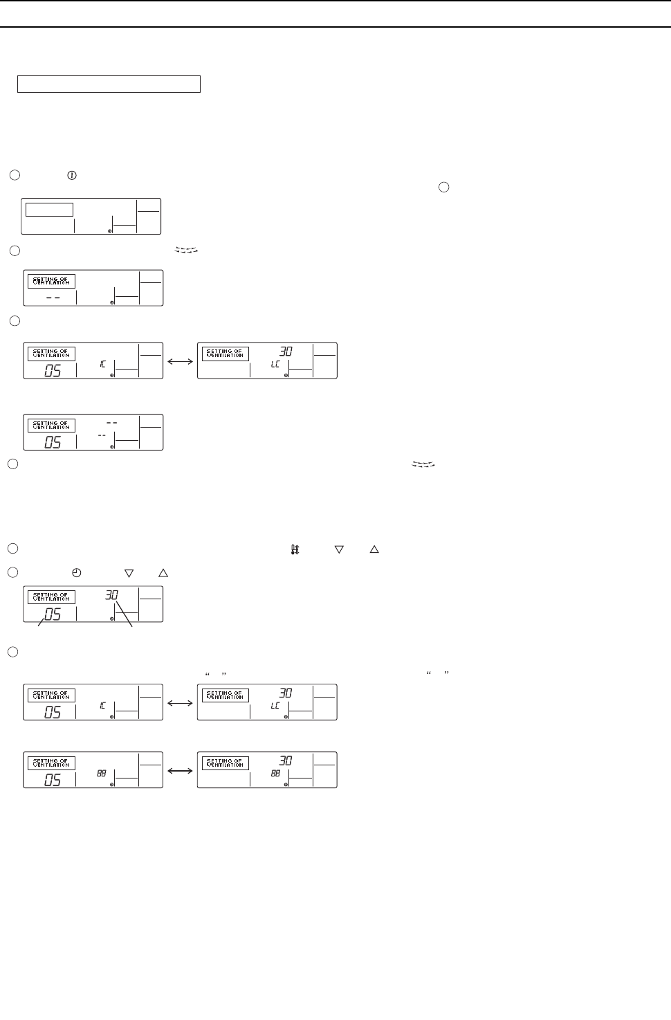
[ IV Remote Controller ]
- 102 -
HWE09080 GB
[3] Interlock Settings via the MA Remote Controller
1. LOSSNAY interlock setting (Make this setting only when making an interlock settings between the LOSSNAY units
and the Freeplan model of units.)
[Operation Procedures]
<Indoor unit address and indoor unit> <LOSSNAY address and LOSSNAY>
- Without interlocked LOSSNAY settings
Search result
- The indoor unit address and the interlocked LOSSNAY address will appear alternately.
Press the [ON/OFF] button on the remote controller to bring the unit to a stop.
The display window on the remote controller must look like the figure below to proceed to step .
Make this setting only when necessary.
Perform this operation to enter the interlock setting between the LOSSNAY and the indoor units to which the remote controller is connected, or to
search and delete registered information.
In the following example, the address of the indoor unit is 05 and the address of the LOSSNAY unit is 30.
2
< 1. Registration Procedures >
Indoor unit address LOSSNAY address
Press the [TEST] button to register the address of the selected indoor unit and the interlocked LOSSNAY unit.
- Registration completed
The registered indoor unit address and IC, and the interlocked LOSSNAY address and LC will appear alternately.
- Registration error
If the registration fails, the indoor unit address and the LOSSNAY address will be displayed alternately.
Registration cannot be completed: The selected unit address does not have a corresponding indoor unit or a LOSSNAY unit.
Registration cannot be completed: Another LOSSNAY has already been interlocked with the selected indoor unit.
1
3
2
Press and hold the [FILTER] and [ ] buttons simultaneously for two seconds to perform a search for the LOSSNAY that is interlocked with the
indoor unit to which the remote controller is connected.
If no settings are necessary, exit the window by pressing and holding the [FILTER] and [ ] buttons simultaneously for 2 seconds.
Go to step 1. Registration Procedures to make the interlock settings with LOSSNAY units, or go to step 2. Search Procedures to search for a
particular LOSSNAY unit.
Go to step 3. Deletion Procedures to delete any LOSSNAY settings.
To interlock an indoor unit with a LOSSNAY unit, press the [ TEMP. ( ) or ( )] button on the remote controller that is connected to the indoor
unit, and select its address (01 to 50).
Press the [ CLOCK ( ) or ( )] button to select the address of the LOSSNAY to be interlocked (01 to 50).
5
4
7
6
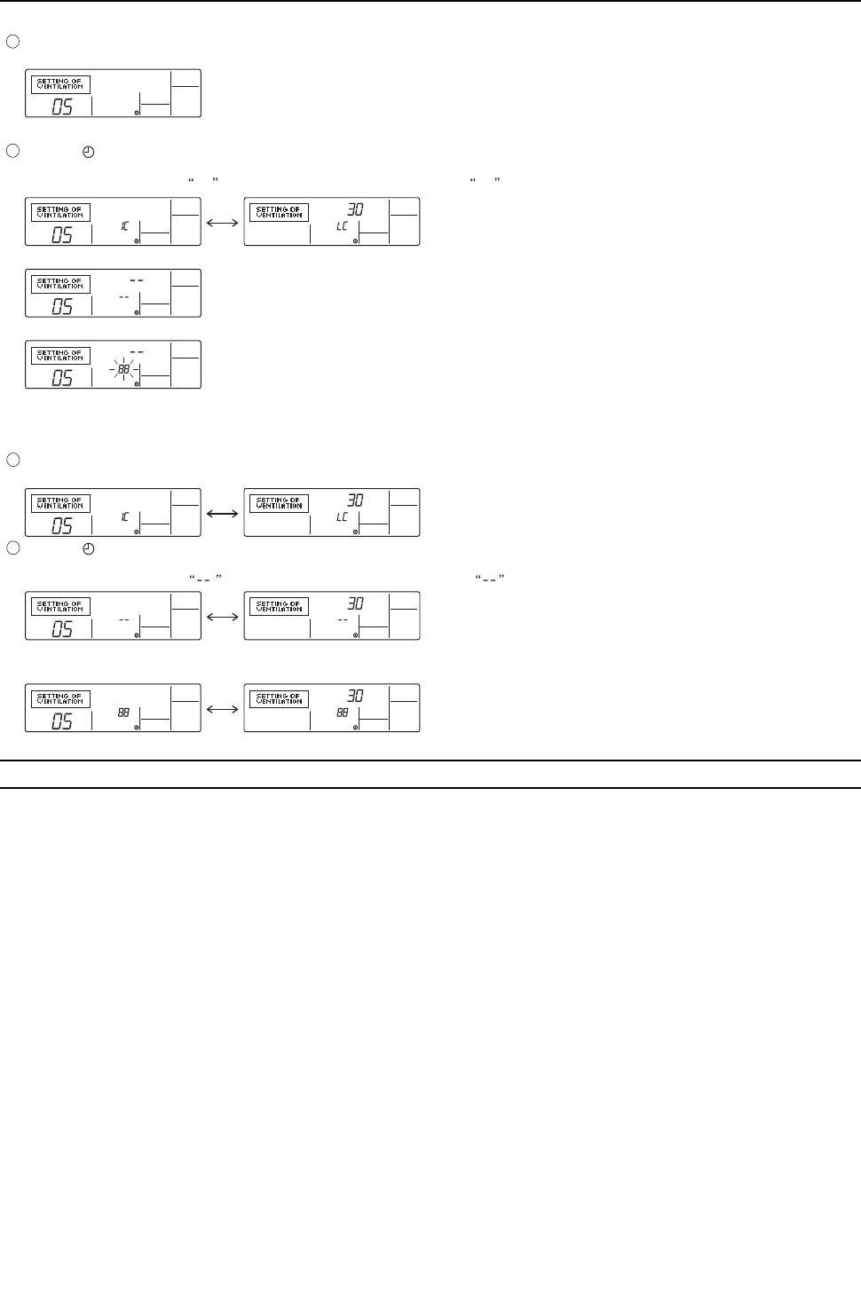
[ IV Remote Controller ]
- 103 -
HWE09080 GB
[4] Using the built-in Temperature Sensor on the Remote Controller
1. Selecting the position of temperature detection (Factory setting: SW1-1 on the controller board on the indoor unit is
set to OFF.)
To use the built-in sensor on the remote controller, set the SW1-1 on the controller board on the indoor unit to ON.
Some models of remote controllers are not equipped with a built-in temperature sensor. Use the built-in temperature sensor
on the indoor unit instead.
When using the built-in sensor on the remote controller, install the remote controller where room temperature can be detected.
<Indoor unit address>
- Search completed (No interlocked settings with a LOSSNAY exist.)
- The selected address does not have a corresponding indoor unit.
< 2. Search Procedures >
< 3. Deletion Procedures >
Press the [ MENU] button to search for the address of the LOSSNAY unit that is interlocked with the selected indoor unit.
- Search completed (With a LOSSNAY connection)
The indoor unit address and IC, and the interlocked LOSSNAY address and LC will appear alternately.
Take the following steps to delete the interlock setting between a LOSSNAY unit and the interlocked indoor unit from the remote controller
that is connected to the indoor unit.
Find the address of the LOSSNAY to be deleted (See section 2. Search Procedures. ), and bring up the result of the search for both the
indoor unit and LOSSNAY on the display.
Press the [ ON/OFF] button twice to delete the address of the LOSSNAY unit that is interlocked with the selected indoor unit.
- Registration completed
The indoor unit address and , and the interlocked LOSSNAY address and will appear alternately.
-Deletion error
If the deletion fails
8
9
10
11
To search for the LOSSNAY unit that is interlocked with a particular indoor unit, enter the address of the indoor unit into the remote controller that is
connected to it.

- 104 -
[ IV Remote Controller ]
GBHWE09080

- 105 -
HWE09080 GB
V
Electrical Wiring Diagram
[1] Electrical Wiring Diagram of the Heat source Unit......................................................... 107
[2] Electrical Wiring Diagram of the BC Controller .............................................................. 111
[3] Electrical Wiring Diagram of Transmission Booster.......................................................120

- 106 -
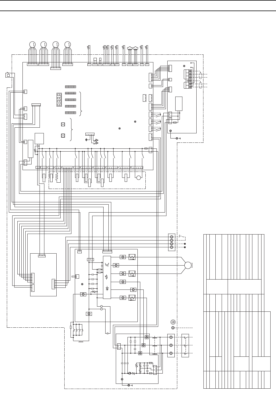
[ V Electrical Wiring Diagram ]
- 107 -
HWE09080 GB
V Electrical Wiring Diagram
[1] Electrical Wiring Diagram of the Heat source Unit
(1) PQHY-P72, 96, 120THMU-A
*7
black
red
C1
+
*6
RELAY Board
4
1
CNAC4
3157
CN83
1346
CNOUT2
yellow
25421
CNPW
blue
Explanation
Symbol
5
4
3
2
1
6
MF1 Fan motor(Radiator panel)
SV1a
t° THINV
1
2
CNTYP1
black
SV4a,b,d
TH8
HIC bypass,Controls refrigerant
flow in HIC circuit
Heat exchanger capacity control
For opening/closing the bypass
circuit under the O/S
Water outlet temperature
LEVINV Heat exchanger for inverter
SV7a,b Heat exchanger capacity control
For opening/closing the bypass
circuit
THINV Outlet temp.detect of heat
exchanger for inverter
LEV2a,b Pressure control,Refrigerant flow
rate control
TH3
TH2 Subcool bypass outlet temperature
Pipe temperature
TH6 Subcooled liquid refrigerant
temperature
<Symbol explanation>
63HS1
SV9
21S4a 4-way valve
Explanation
Symbol
63H1
63LS
Pressure
sensor
Pressure
switch High pressure protection for the
heat source unit
High pressure
Low pressure
72C Magnetic relay(inverter main circuit)
Current sensor(AC)
Crankcase heater(for heating the compressor)CH11
CN506
6
3
CT12,22,3
Solenoid
valve
Linear
expansion
valve
t° TH8
CN992
yellow
yellow
1
2
M
LEVINV
CNLVE
6
5
4
3
2
1
LEV1
DCL DC reactor
TB1
TB3
TB7
Terminal
block
Central control transmission
cable
Indoor/Heat source transmission
cable
Power supply
TB8
TH4
TH5
TH7
THHS
Function setting connector
IGBT temperature
Water inlet temperature
ACC inlet pipe temperature
Discharge pipe temperature
Operation ON signal,
Pump Interlock
Thermistor
Z24,25
ZNR01
CNOUT1
yellow
U
5
X05
X06
SV7a
SV7b
M
MF1 ~
1
6
5
1
CN510
yellow
CN509
blue
X12
5
6
SV4a
X07
3
6
CN507
red
red
white
1
6
3
X09
CN508
black
SV9
L3
L2
L1
1
*1.Single-dotted lines indicate wiring
not supplied with the unit.
*2.Dot-dash lines indicate the control box boundaries.
*3.Refer to the Data book for connecting input/output signal connectors.
*4.Daisy-chain terminals (TB3) on the heat source units
in the same refrigerant system together.
*5.Faston terminals have a locking function.
Make sure the terminals are securely locked in place after insertion.
Press the tab on the terminals to remove them.
*6.Refer to the Data book for wiring terminal block for
Pump Interlock and Operation ON signal.
*7.Control box houses high-voltage parts.
Before inspecting the inside of
the control box,turn off the power,
keep the unit off for at least 10 minutes,
and confirm that the voltage at both ends
of the main capacitor (C1) has dropped to
DC20V or less.
SV1a
72C
CN504
green
3
1
CH11
A2
A1
3
1X03
CN503
blue
3
1
CN505
2
1X02
X72
CN502
1
CN02
Motor
(Compressor)
TB21
F2
AC250V
6.3A T
31 21 CNT01
CNDC
pink
CPU power
supply circuit
1
F01
AC250V
3.15A T
CN03
black 1313
M-NET power
supply
circuit
12
blue
orange
red
yellow
M-NET Board
*4
7
TH2
TH4
t°
t°
3
2
1
Indoor/Outdoor
transmission
cable
Central control
transmission
cable
63HS1
5
red
CNAC
63LS
3
TP2
2
CN2
1
Control Board
M
LEV1
LEV2a
3
TH5
LEV2b
M
TP1
TH6
TH7
M
2
3
4
5
TH3
6
TB3
M1 M2 M1 M2 S
TB7
123
t°
4512
1234
t°
1
t°
2
LED1
Unit address
setting
t°
LED1:Power supply to
Indoor/Outdoor
transmission line
CN102 CNS2
yellow
SWU2
10's digit
SWU1
1's digit
10
1
10
1
10
1
10
1
SW4 SW3 SW2 SW1
ON
SV4b
1
5
X14
OFF ON OFF ON OFF ON
X04
X08
SV4d
*3
43
2
TB8 1
Pump Interlock
Operation
ON signal
*6
LED3:Lit when powered
CN01 5
black
3
CNIT
red
1
1
3
6
5
4
3
1
2
blue
CN63PW
24
2
1
2
1
1
2
1
1
OFF
2323123
blue
CN3N
yellow
CN3K
F01
AC250V
3.15A T
4521
OFF
4112 431
2
1
2
3
4
5
6
21
CNLVC
red
CNLVA
2131
CN801
yellow
CNT02 CN4
2
1
2
2
3
3
CN41CN102CN3D
4
1
red
CNIT
yellow
CNS2
CN202
red
CN201
CN215
black
CN211
41
2
1
Z24
Z25
3
CNLVB
red
ON
CNTYP5
green
CNTYP4
green
CN990
CN40
LED2:CPU in operation
CN212
CN213
red
TB1 L3L2
whitered
Noise Filter
F1
AC250V
6.3A T
W
CX6
CY3
V
black
SC-V 7
black
INV Board
RSH2
3
ZNR1
C32
red black
CN6
SC-U
CN2
SC-T
MS
3~
*5
CX5
U
CN4
red
white
U
72C
R30
TB23
TB22
1
CT22
DSA1
black
1
CX2
CY1
CX1
Z3
CX3
Z4
Z1
U
SC-P2
3
CY2
CX4
black
white
*5
red
red
CT12
black
SC-W
1
SC-S
red
CT3
SC-R
red
R1
DCL
2
5
C31
C1
RSH1
UC30
IGBT
CNDC
pink
LED1:Normal operation(Lit)
/Error(Blink)
2
1
THHS
1
L
TB-P
44
3334
*5
1314
23
43
24
white
white
21S4a
+++
TB-N
SC-P1
1
P
63H1
Power supply
3~
60Hz
208/230V
CN04
red
U
Z2
U
ONOFF
1
10
SW5
12V
5
4
3
1
CN51
*3
Function setting
LED1
Display
setting
Compressor ON/OFF output
Error detection output
L1
1
CNAC2
black
black
1
2
G
Ground
G
Power
failure
detection
circuit
TB7 Power
selecting
connector
t°
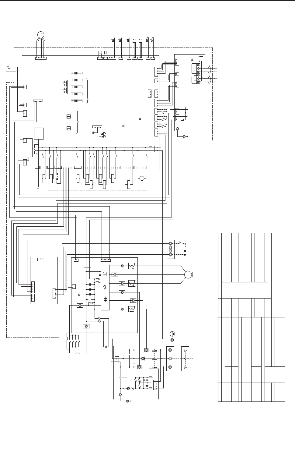
[ V Electrical Wiring Diagram ]
- 108 -
HWE09080 GB
(2) PQRY-P72, 96, 120THMU-A
()
red
black
*7
C1
+
*6
<Symbol explanation>
Explanation
Symbol
MF1 Fan motor(Radiator panel)
SV1a
SV4a,b,d
TH8
Heat exchanger capacity control
For opening/closing the bypass
circuit under the O/S
Water outlet temperature
LEVINV Heat exchanger for inverter
SV7a,b Heat exchanger capacity control
For opening/closing the bypass
circuit
THINV Outlet temp.detect of heat
exchanger for inverter
63HS1
SV9
21S4a 4-way valve
CN215
black
2
1THINVt°
Explanation
Symbol
63H1
63LS
Pressure
sensor
Pressure
switch High pressure protection for the
heat source unit
High pressure
Low pressure
72C Magnetic relay(inverter main circuit)
Current sensor(AC)
Crankcase heater(for heating the compressor)
CNOUT1
yellow
CH11
CT12,22,3
Solenoid
valve
Linear
expansion
valve
DCL DC reactor
TB1
TB3
3
4
5
6
t° TH8
CN992
yellow
yellow
2
1
LEVINV
M
6
5
CNLVE 4
3
2
1
TB7
X05
3
6
CN506
6
L3
L2
L1
Terminal
block
*1.Single-dotted lines indicate wiring
not supplied with the unit.
*2.Dot-dash lines indicate the control
box boundaries.
*3.Refer to the Data book for connecting input/output signal connectors.
*4.Daisy-chain terminals (TB3) on the heat source units
in the same refrigerant system together.
*5.Faston terminals have a locking function.
Make sure the terminals are securely locked in place after insertion.
Press the tab on the terminals to remove them.
*6.Refer to the Data book for wiring terminal block for
Pump Interlock and Operation ON signal.
*7.Control box houses high-voltage parts.
Before inspecting the inside of
the control box,turn off the power,
keep the unit off for at least 10 minutes,
and confirm that the voltage at both ends
of the main capacitor (C1) has dropped to
DC20V or less.
SV1a
72C
CN504
green
3
1
CH11
A2
A1
3
1
Central control transmission
cable
X03
Indoor/Heat source transmission
cable
Power supply
TB8
TH4
TH5
TH7
THHS
Function setting connector
CN503
blue
3
1X72
CN505
2
1X02
CN502
CN02
Motor
(Compressor)
TB21
F2
AC250V
6.3A T
IGBT temperature
Water inlet temperature
ACC inlet pipe temperature
Discharge pipe temperature
Operation ON signal,
Pump Interlock
Thermistor
Z24,25
5
31 21 CNT01
CNDC
pink
CN83
753
CPU power
supply circuit
1
F01
AC250V
3.15A T
CN03
black 13
2
13
M-NET power
supply
circuit
12
M-NET Board
*4
7
1
TH4t°
3
2
1
Indoor/Outdoor
transmission
cable
Central control
transmission
cable
63HS1
5
CNAC
red
63LS
3
TP2
2
CN2
1
Control Board
Pump Interlock
Operation
ON signal
*6
3
TH5
TP1
TH7
TB3
M1 M2 M1 M2 S
TB7
123
t°
4512
1234
t°
2
RELAY Board
LED1
Unit address setting
LED1:Power supply to
Indoor/Outdoor
transmission line
5
CN102 CNS2
yellow
SWU2
10's digit
SWU1
1's digit
10
1
10
1
10
1
10
1
SW4 SW3 SW2 SW1
ON OFFON OFFON OFFON
X04
6
*3
CNOUT2
yellow
21
4
32
CNPW
blue
TB8
1
LED3:Lit when powered
CN01
1
24
5
black
3
CNIT
red
1
1
SV7a
4
3
1
2
1
1
CNAC4
blue
CN63PW
24
2
1
blue
orange
1
1
red
yellow
2
1
OFF
2323123
blue
CN3N
yellow
CN3K
F01
AC250V
3.15A T
4521
OFF
4112 431
21
X08
2131
CN801
yellow CNT02
1
CN4
X09
CN508
black
1
3
6
SV7b
1
2
23
CN41CN102CN3D
4
1
red
CNIT
yellow
CNS2
CN202
red
CN201
CN211
41
2
1Z24
Z25
3
X06
SV9
ON
CNTYP5
green
CNTYP4
green
CN990
CN40
LED2:CPU in operation TB7 Power
selecting
connector
CN213
red
TB1 L3
L2
whitered
Noise Filter
F1
AC250V
6.3A T
W
CX6
CY3
V
black
SC-V 7
t°
black
INV Board
RSH2
3
ZNR1
C32
red black
CN6
SC-U
CN2
SC-T
MS
3~
*5
CX5
U
CN4
red
white
U
72C
R30
TB23
TB22
1
CT22
DSA1
black
1
CX2
CY1
CX1
Z3
CX3
Z4
Z1
U
SC-P2
3
CY2
CX4
black
white
*5
red
red
CT12
black
SC-W
1
SC-S
red
CT3
SC-R
red
R1
DCL
2
C31
C1
RSH1
UC30
IGBT
CNDC
pink
LED1:Normal operation(Lit)
/Error(Blink)
2
1
THHS
1
L
TB-P
44
3334
*5
1314
23
43
24
white
white
21S4a
+++
TB-N
SC-P1
1
5
P
63H1
Power supply
3~
60Hz
208/230V
CN04
red
43
U
Z2
U
ONOFF
1
10
SW5
12V
5
4
3
1
CN51
*3
Function setting
LED1
Display
setting
Compressor ON/OFF output
Error detection output
L1
G
Ground
G
CN510
yellow
6
5
X14
~
M
X12
1
5
MF1
SV4b X07
CN507
red
red
white
1
5
3
6
SV4d
SV4a
ZNR01
CNAC2
black
black
1
2U
CN509
blue
Power
failure
detection
circuit
1
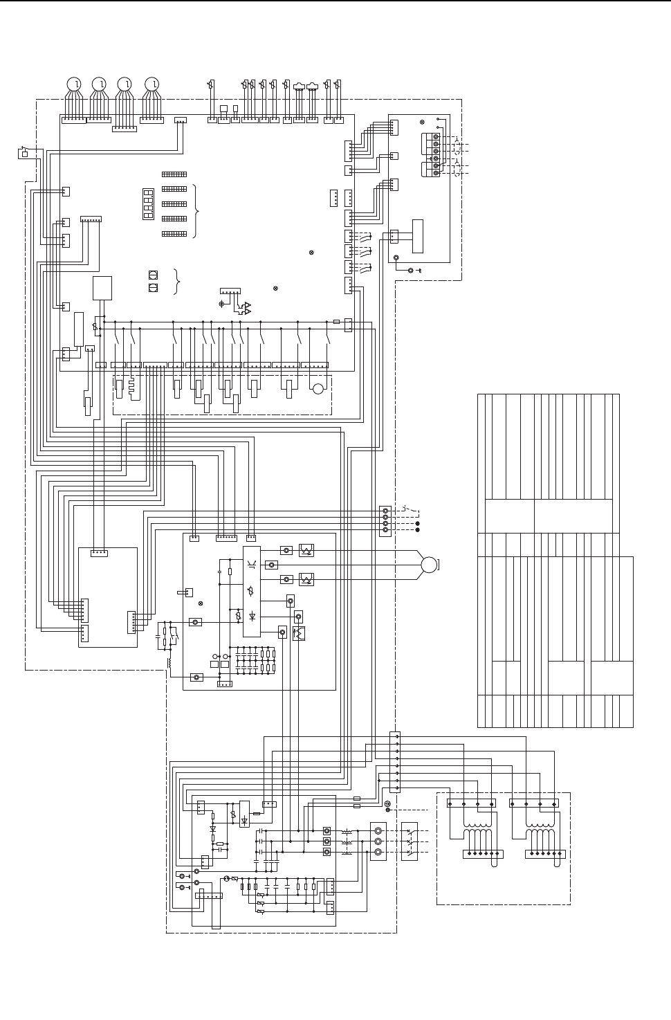
[ V Electrical Wiring Diagram ]
- 109 -
HWE09080 GB
(3) PQHY-P72, 96, 120YHMU-A
㧗
1
2
*7
Z24,25
Thermistor
Operation ON signal,
Pump Interlock
Discharge pipe temperature
ACC inlet pipe temperature
Water inlet temperature
IGBT temperature
Function setting connector
THHS
TH7
TH5
TH4
TB8
Power supply
Indoor/Heat source transmission
cable
Central control transmission
cable
Terminal
block
TB7
TB3
TB1
Subcooled liquid refrigerant
temperature
TH6
Pipe temperature
Subcool bypass outlet temperature
TH2
TH3
Outlet temp.detect of heat
exchanger for inverter
THINV
Water outlet temperatureTH8
Explanation
Symbol
L1 L2
Power Source
ޓ3~
ޓ60Hz
ޓ460V
Transformer box
purple 1
2
3
4
CN06
T02
(Transformer)
CNTR2
CN07
1
2
3
4
5
6
T03
(Transformer)
CNTR3
5
6
2
4
3
1
460V
460V
purple
1
X09
3
6
CN508
black
Unit address
setting
CN504
green
CT12
C31
C33
CN5
red
D1 R5
Z5
1
SV9
CNTR1
12
L1 L2 L2
3
L3
45678
white
TH2
t°
white
red
black
black
white
red
F4
AC 600V
3A F
C8
F5
AC 600V
3A F
red
CNIT
yellow
CNS2
t°
1
CN51
12V
Function
setting
SW1
10
1
CN212
CNTYP4
green
F4
AC250V
6.3A T
R4
F3
F1
Z4
R2
F2
*3
3
2
Compressor ON/OFF output
Error detection output
CN201
Z25
1
4
1
1
1
TH3
Z3Z2
U
ONOFF
SW2
10
1
SWU2
LED1
C4
C35
C37
R31
R33
R30
ON
SW3
10
Control Board
TH7
CN40
63HS1
CN41
TH6
t°
t° TH4
3
2
2
2
1
SW5
LED3:Lit when powered
1
3
4
R32
2
Z1
1
DSA
C10
R34 R35
LEV1
LEV2a
C36
3
C34
SC-V
CT22
SC-U
V
1
CN4
blue
red
1
M
1
LEV2b
t°
black
4
1
3
6
yellow
CN3K
*3
3
M
C3
TB21
C1
R3
3
M
CN1A
5
U
CN2
blue
CN3N
5
6
C7
U
44
R1
TB1
CN1B
3
TB7 Power
selecting
connector
CN102
3
2
12
1
U
TP1
L3
DCL
black
72C
white
red
321
ON
OFF
1
M-NET power
supply circuit
123
C6
M-NET Board
12
1
1
CNAC2
black
CN502
5
Indoor/Outdoor
transmission
cable
INV Board red
3
CNT01
TB23
L2L1
1
ON
1
2
1's
digit
THHS
1
CNIT
red
S
2
1
1
CN990
1
WTB3
10's
digit
OFF
LED2:CPU in operation
5
2
CNS2
yellow
TB7
1
CNDC
pink
M1
2
red
6
MS
3~
1
1
t°
C100
*5
3
3
U
1
4
LED1:Power supply to
Indoor/Outdoor
transmission line
ZNR01
M2
32
M1
black
Central control
transmission
cable
*6
SC-L1
4
C2
C9
ON
C5
OFF
FT-N
R5
Motor
(Compressor)
5
2
3
3
1
CN04
red
CN2
3
CN4
X05
2
SC-P2
P
1
CN211
CN202
red
TH5
N
CN1
M2
2
TP2
LED1:Normal operation(Lit)
/ Error(Blink)
2
CN503
blue
5
X04
4
*4
SC-W
U
C32
SC-L3
CH11
CN506
1
2
CN72
red
3
P63H1
CN801
yellow
1
2
F1,F2,F3
AC250V
6.3A T
21
OFF
SW4
10
CNT02
1
CN3D
432
1
21
CPU power
supply circuit
CNAC
red
2
1
F01
AC250V
3.15A T
1
t
CN507
red
ONOFF
10
SWU1
white
CN213
red
SC-L2
3
Z24
7
4
32121
1
CN83
31
3
1
CNTYP5
green
21S4a
U
X02
X03
5
1
7
CN4
CN6
IGBT
4
SC-P1
FT-P
black
C30
red
Diode
Bridge
CT3
72C
C1 CN2
R1
black
TB22
3
RSH1
CN102
3
R6
C17
1
1
63LS
ZNR1
U
L
Noise
Filter X08
3
1
CN6
yellow
red
SV4a
X07
3
5
6
4
3
2
CNLVA
CNLVB
red
CNLVC
red
1
2
3
4
5
6
white black
SV1a
1
G
Ground
6
5
4
3
2
1
6
G
5
4
G
3
2
1
2
L1 L2 L3
1
CN215
black
L3
MF1 Fan motor(Radiator panel)
SV1a
SV4a,b,d
HIC bypass,Controls refrigerant
flow in HIC circuit
Heat exchanger capacity control
For opening/closing the bypass
circuit under the O/S
LEVINV Heat exchanger for inverter
SV7a,b Heat exchanger capacity control
For opening/closing the bypass
circuit
LEV2a,b Pressure control,Refrigerant flow
rate control
<Symbol explanation>
63HS1
SV9
21S4a 4-way valve
Explanation
Symbol
63H1
63LS
Pressure
sensor
Pressure
switch High pressure protection for the
heat source unit
High pressure
Low pressure
72C Magnetic relay(inverter main circuit)
Current sensor(AC)
Crankcase heater(for heating the compressor)CH11
CT12,22,3
Solenoid
valve
Linear
expansion
valve
LEV1
DCL DC reactor
Power
failure
detection
circuit
1
2
3
4
5
6
orange
3
Pump Interlock
Operation
ON signal
*7
TB8 1
blue
4
yellow
4
1
red
CNAC4
CNPW
blue
2
25613
CNOUT1
yellow
4
CNOUT2
yellow
5
X12
1
X06
M
㨪
X14
6
CN510
yellow
blue
CN63PW
421
1
5
MF1
SV7a
6
CN509
blue
THINV
t°
CNTYP1
black 1
2
SV7b
t° TH8
LEVINV
SV4d
1
SV4b
1
2
M
1
CN992
yellow
24
75
CNLVE
6
5
4
3
2
1
5
RELAY Board
CNTYP
black
3
1
CNTYP2
black
1
3
*1.Single-dotted lines indicate wiring not supplied with the unit.
*2.Dot-dash lines indicate the control box boundaries.
*3.Refer to the Data book for connecting input/output signal connectors.
*4.Daisy-chain terminals (TB3) on the heat source units in the
same refrigerant system together.
*5.Faston terminals have a locking function.
Make sure the terminals are securely locked in place after insertion.
Press the tab on the terminals to remove them.
*6.Control box houses high-voltage parts.
Before inspecting the inside of the control box,turn off the power,
keep the unit off for at least 10 minutes, and confirm that the voltage
between FT-P and FT-N on INV Board has dropped to DC20V or less.
*7.Refer to the Data book for wiring terminal block for
Pump Interlock and Operation ON signal.
LED1
Display
setting
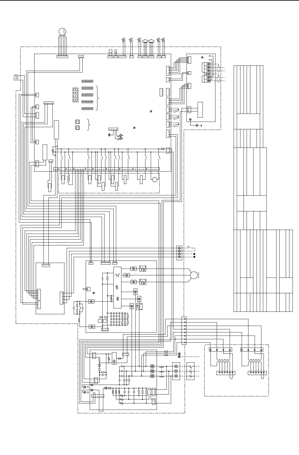
[ V Electrical Wiring Diagram ]
- 110 -
HWE09080 GB
(4) PQRY-P72, 96, 120YHMU-A
()
+
-++
+
+
1
2
+
++
++
*7
Solenoid
valve
Symbol Explanation
TH8 Water outlet temperature
THINV Outlet temp.detect of heat
exchanger for inverter
TB1
TB3
TB7
Terminal
block
Central control transmission
cable
Indoor/Heat source transmission
cable
Power supply
TB8
TH4
TH5
TH7
THHS
Function setting connector
IGBT temperature
Water inlet temperature
ACC inlet pipe temperature
Discharge pipe temperature
Operation ON signal,
Pump Interlock
Thermistor
Z24,25
Explanation
Symbol
MF1 Fan motor(Radiator panel)
SV1a
SV4a,b,d Heat exchanger capacity control
For opening/closing the bypass
circuit under the O/S
LEVINV Heat exchanger for inverter
SV7a,b Heat exchanger capacity control
For opening/closing the bypass
circuit
63HS1
SV9
21S4a 4-way valve
Explanation
Symbol
63H1
63LS
Pressure
sensor
Pressure
switch High pressure protection for the
heat source unit
High pressure
Low pressure
72C Magnetic relay(inverter main circuit)
Current sensor(AC)
Crankcase heater(for heating the compressor)CH11
CT12,22,3
Solenoid
valve
Linear
expansion
valve
DCL DC reactor
<Symbol explanation>
CNTYP
black
3
1
12 4
blue
CN63PW
t°THINV
1
2
M
LEVINV
5
6
1
2
3
4
CNLVE
purple
CN215
black
X12
5
6
1
CN509
blue
1
CN510
yellow
CNOUT1
yellow
6
5
4
*7
Operation
ON signal
Pump Interlock
3
1
TB8 234
red
orange
1
yellow
blue
4
2
1
1
X09
3
6
Ground
GG
G
CN508
black
SV7a
Unit address
setting
CN504
green
CT12
C31
C33
CN5
red
D1 R5
Z5
Power Source
3~
60Hz
460V
SV7b
SV4b
1
3
white
Transformer box
X14
2
CN07
1
2
3
4
4
CN06
8
CNTR1
3
1
4
1
T02
(Transformer)
CNTR2
5
712
6
65
2
white
red
black
black
white
red
F4
AC 600V
3A F
C8
F5
AC 600V
3A F
red
CNIT
yellow
CNS2
t°
1
LED1
Display
setting
CN51
12V
Function
setting
SW1
10
1
CN992
yellow
CNTYP4
green
F4
AC250V
6.3A T
R4
F3
F1
Z4
R2
F2
*3
3
2
Compressor ON/OFF output
Error detection output
CN201
Z25
1
4
1
1
1
TH8
Z3
1
Z2
U
ONOFF
SW2
10
1
SWU2
LED1
4
C4
C35
C37
R31
R33
R30
ON
SW3
10
Control Board
TH7
CN40
63HS1
CN41
t
°
tTH4
3
2
2
2
1
SW5
LED3:Lit when powered
1
3
4
R32
2
Z1
1
1
DSA
C10
R34 R35
C36
3
C34
SC-V
CT22
SC-U
CN6
yellow
V1
CN4
blue
red
1
1
t
L3
black
4
1
3
6
yellow
CN3K
*3
3
C3
TB21
C1
R3
CN1A
5
U
CN2
blue
CN3N
5
6
C7
U
44
R1
TB1
CN1B
3
TB7 Power
selecting
connector
CN102
3
2
12
1
U
TP1
6
L3
DCL
5
black
72C
white
red
321
ON
OFF
1
M-NET power
supply circuit
123
C6
M-NET Board
12
1
Power failure
detection circuit
1
CNAC2
black
CN502
5
Indoor/Outdoor
transmission
cable
INV Board red
3
CNT01
TB23
L2L1
1
ON
1
2
1's
digit
THHS
1
CNIT
red
S
2
1
1
CN990
1
W
TB3
10's
digit
OFF
LED2:CPU in operation
5
2
CNS2
yellow
TB7
1
CNDC
pink
M1
2
red
6
MS
3~
1
1
C100
*5
3
3
U
1
4
LED1:Power supply to
Indoor/Outdoor
transmission line
X06
ZNR01
M2
32
M1
black
Central control
transmission
cable
*6
SC-L1
4
C2
C9
ON
C5
OFF
FT-N
R5
CNAC4
Motor
(Compressor)
5
2
3
3
1
CN04
red
4
CN2
3
CN4
X05
2
SV4d
3
SC-P2
P
1
CN211
CN202
red
TH5
°
N
CN1
M2
2
TP2
LED1:Normal operation(Lit)
/ Error(Blink)
2
CN503
blue
5
X04
4
*4
SC-W
U
C32
SC-L3
CH11
CN506
1
2
CN72
red
3
P63H1
CN801
yellow
1
2
2
F1,F2,F3
AC250V
6.3A T
21
OFF
SW4
10
black
1CNT02
1
CN3D
432
1
21
CPU power
supply circuit
CNAC
red
2
1
F01
AC250V
3.15A T
1
t
CN507
red
ONOFF
10
SWU1
white
CN213
red
SC-L2
3
Z24
7
4
°
3 21
CNOUT2
yellow
2131
4
white
3
red
21
CNPW
blue
1
CNTYP5
green
21S4a
U
X02
X03
5
1
3
7
CN4
CN6
°
IGBT
4
SC-P1
FT-P
black
C30
red
Diode
Bridge
CT3
72C
C1 CN2
R1
black
TB22
RSH1
CN102
3
R6
C17
1
1
RELAY Board
63LS
ZNR1
U
L
Noise
Filter
L3L2L1
X08
3
13
SV4a
SV9
X07
75
CN83
3
5
6
460V
1
3
4
2
CNTR3
T03
(Transformer)
6
5
6
5
L3
L1
L2L2
L2
L1
purple
460V
SV1a
CNTYP2
black
1
3
~
M
MF1
*1.Single-dotted lines indicate wiring not supplied with the unit.
*2.Dot-dash lines indicate the control box boundaries.
*3.Refer to the Data book for connecting
input/output signal connectors.
*4.Daisy-chain terminals (TB3) on the heat source units
in the same refrigerant system together.
*5.Faston terminals have a locking function.
Make sure the terminals are securely locked in place after
insertion. Press the tab on the terminals to remove them.
*6.Control box houses high-voltage parts.
Before inspecting the inside of the control box,
turn off the power,keep the unit off for at least 10 minutes,
and confirm that the voltage between FT-P and FT-N
on INV Board has dropped to DC20V or less.
*7.Refer to the Data book for wiring terminal block for
Pump Interlock and Operation ON signal.
5
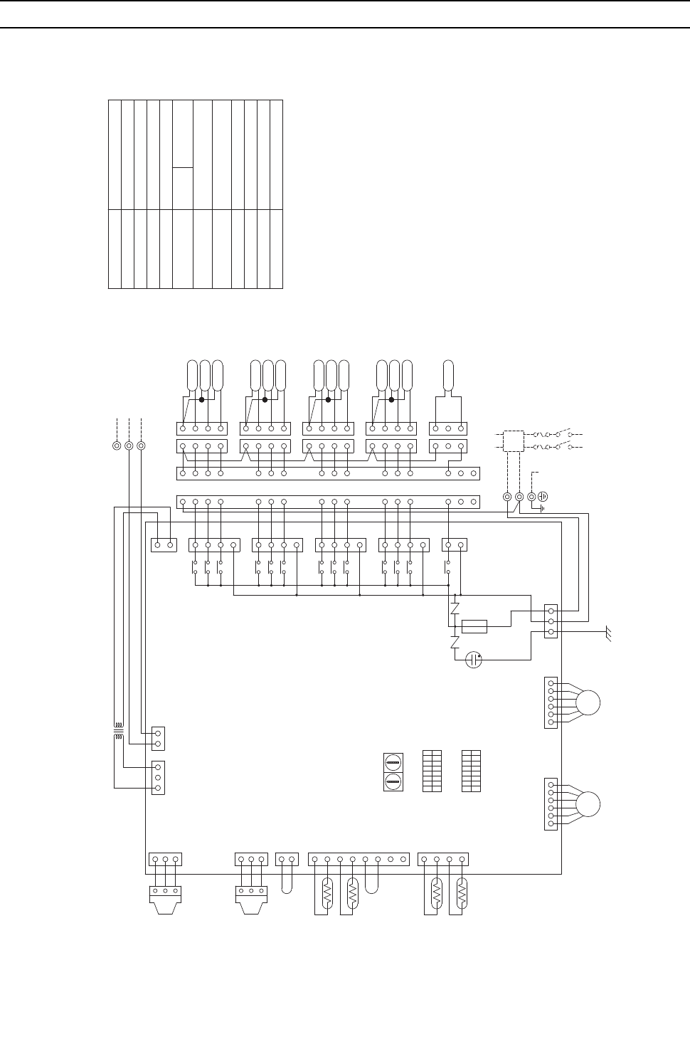
[ V Electrical Wiring Diagram ]
- 111 -
HWE09080 GB
[2] Electrical Wiring Diagram of the BC Controller
(1) CMB-P104NU-G model
(Red)
CNTR
ZNR02
ZNR01
L2
X21
CN36(Green)
3
1
3
2
1
3
2
1
SVM1
CN29(Green)
X33
X7
X8 1
3
5
7
1
4
3
2
1
14
16
15
SV4A
SV4C
SV4B
11
12
13
14
15
16
11
12
13
4
3
2
11
11
CN28(Blue)
CN27(Red)
X32
X5
X6
X31
X3
X4
X30
X1
X2 1
3
5
7
1
3
5
7
1
3
5
7
SV1B
SV1A
SV1C
5
6
7
8
9
4
3
2
4
3
2
1
4
3
2
1
2
3
4
6
5
7
3
4
2
SV2A
SV2C
SV3C
SV2B
SV3B
SV3A
3
4
1
2
10
3
2
4
8
9
10
4
3
2
1
L1
M1
M2
S(SHIELD)
LEV3
TB01
LEV1
123456
PS3
PS1
TH16
TH15
TH12
TH11
CN07
CN11
CN10
CN13
CN03
12321
1
2
3
4
8
7
6
5
4
3
2
1
1
2
CNP3
3
2
1
CNP1
3
CN02
2
1
CONT.B
123456
CN05
35
1
CN12
1
3
CN26
TB02
TR
SVM1 Solenoid valve
Fuse AC250V 6.3A F
F01
Terminal
T1~4
Terminal block
(for Transmission)
TB02
Terminal block
(for power source)
TB01
Solenoid valve
SV1~4A,B,C
Expansion valve
Thermistor sensor
Transformer
Name
Symbol
TR
TH11,12,15,16
LEV1,3
PS1,3 Pressure sensor
CONT.B
Note:1.TB02 is transmission
terminal block.
Never connect power
line to it.
2.The initial set values
of switch on CONT.B
are as follows.
SW1:0
SW2:0
Indoor/outdoor (heat source)
Transmission Line
~208V-230V 60Hz
POWER SUPPLY
BREAKER(15A)
FUSE(15A)
PULL BOX
TO NEXT INDOOR UNIT
G
T4
T1
T3
T2
1
3
1
3
G
2
2
8
1
ON
SW4
8
OFF
SW5
1
OFF
ON
DSA
(Yellow)
(Red)
(Yellow)
(Red)
(Black)
F01
250VAC
6.3A F
10 1
SW1SW2
Circuit
board
(Symbol explanation)
BC controller
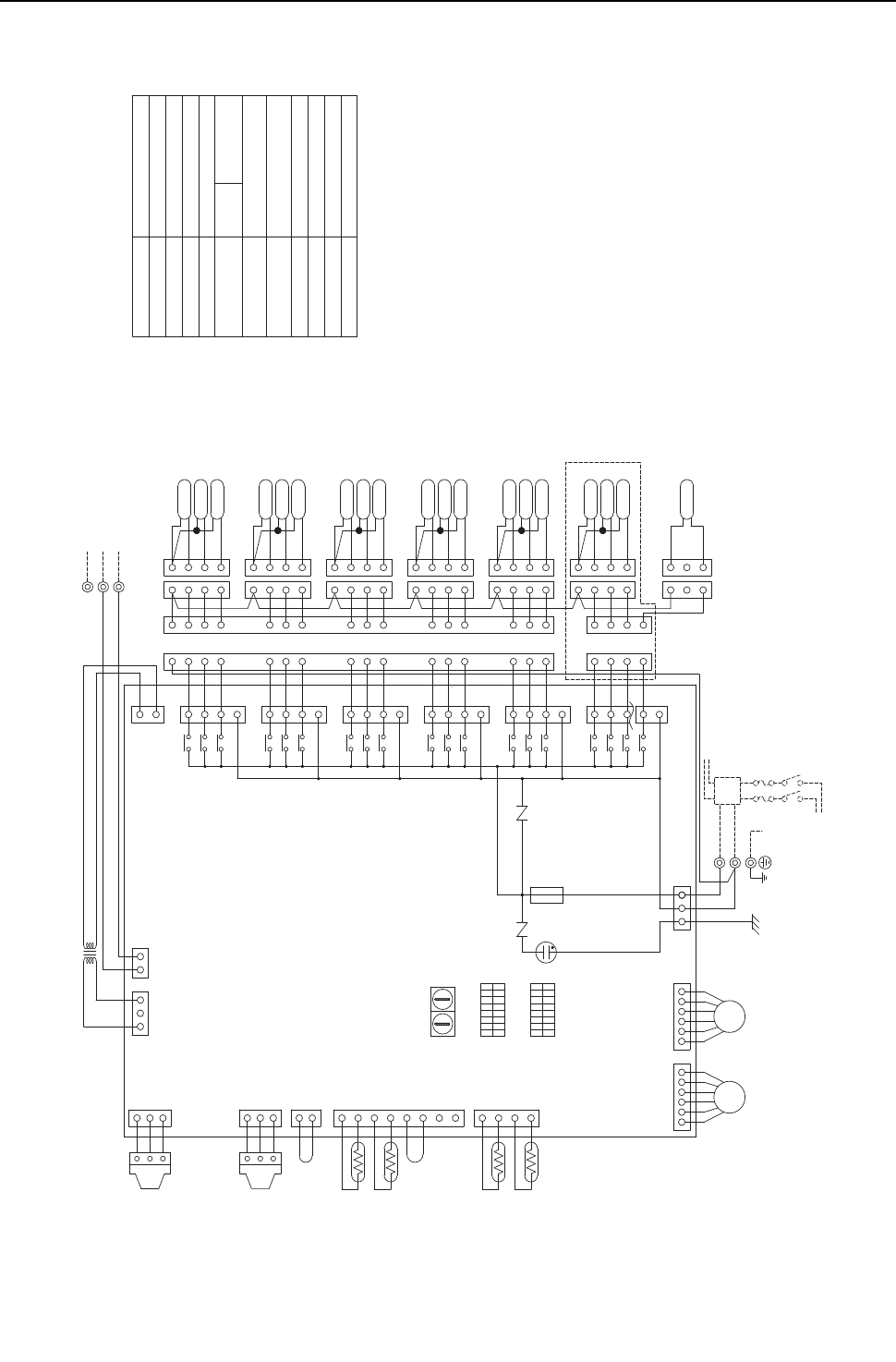
[ V Electrical Wiring Diagram ]
- 112 -
HWE09080 GB
(2) CMB-P105,106NU-G models
CN36(Green)
L2
L1
ZNR02
CN29(Green)
CN28(Blue)
CN27(Red)
ZNR01
CN05
CN07
S(SHIELD)
M1
M2
TB02
X21
1
3
SVM1
3
2
1
2
3
1
TR
CN26
3
CNTR
1
CN12
153
6
54
3
2
1
CONT.B
1
2
CN02
3
CNP1
1
2
3
CNP3
2
1
1
2
3
4
5
6
7
8
4
3
2
1
12321
CN03
CN13
CN10
CN11
TH11
TH12
TH15
TH16
PS1
PS3
6
54
3
2
1
TB01
LEV3 LEV1
1
2
3
4
10
9
8
4
2
3
10
2
1
4
3
SV3A
SV3B
SV2B
SV3C
SV2C
SV2A
2
4
3
7
5
6
4
3
2
1
2
3
4
1
2
3
4
2
3
4
9
8
7
6
5
SV1C
SV1A
SV1B
7
5
3
1
7
5
3
1
7
5
3
1
X2
X1
X30
X4
X3
X31
X6
X5
X32
1
11
1
2
3
4
13
12
11
16
15
14
13
12
11
SV5A
SV5C
SV4B
SV5B
SV4C
SV4A
15
16
14
1
2
1
4
2
3
4
34
3
2
1
4
3
2
1
SV6C
SV6A
SV6B
1
2
3
4
1
2
3
4
1
2
3
4
1
5
3
1
7
5
3
1
7
5
3
1
X8
X7
X33
X10
X9
X34
X12
X11
X35
CN30(Black)
CN31(Yellow)
Solenoid valve
SVM1
CONT.B
Pressure sensor
TR
TH11,12,15,16
LEV1,3
PS1,3
Symbol Name
Transformer
Thermistor sensor
Expansion valve
SV1~6A,B,C Solenoid valve
TB01 Terminal block
(for power source)
TB02 Terminal block
(for Transmission)
T1~6 Terminal
F01 Fuse AC250V 6.3A F
Note:1.TB02 is transmission
terminal block.
Never connect power
line to it.
2.The initial set values
of switch on CONT.B
are as follows.
SW1:0
SW2:0
TO NEXT INDOOR UNIT
PULL BOX
FUSE(15A)
BREAKER(15A)
POWER SUPPLY
~208V-230V 60Hz
GG
Indoor/outdoor (heat source)
Transmission line
2
2
3
1
3
1
T2
T3
T1
T6
T4
T5
ON
OFF
1
SW5
OFF
8
SW4
ON
1
8
(Yellow)
(Red)
DSA
(Red)
(Yellow)
(Red)
(Black)
SW2 SW1
110
CMB-P106NU-G ONLY
F01
250VAC
6.3A F
BC controller
(Symbol explanation)
Circuit
board
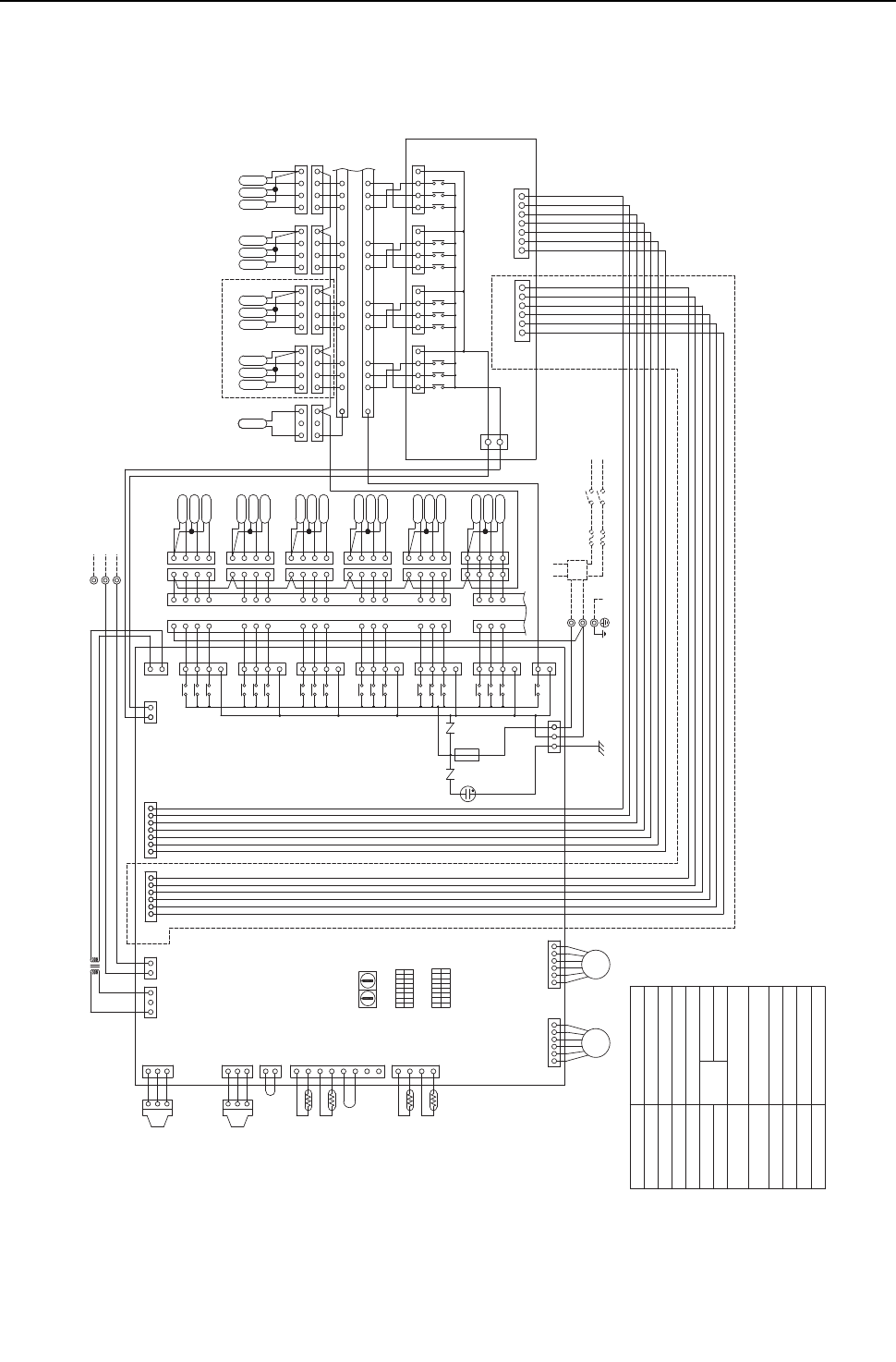
[ V Electrical Wiring Diagram ]
- 113 -
HWE09080 GB
(3) CMB-P108,1010NU-G models
2.The initial set values
of switch on CONT.B
are as follows.
SW1:0
SW2:0
Pressure sensor
TR
TH11,12,15,16
LEV1,3
PS1,3
SV1~10A,B,C
Symbol Name
Transformer
Thermistor sensor
Expansion valve
Solenoid valve
TB01 Terminal block
(for power source)
TB02 Terminal block
(for Transmission)
CONT.B
T1~10 Terminal
Fuse AC250V 6.3A F
F01
Solenoid valve
SVM1
CN51
CN53
654321123456
654321
(Red)
ZNR01 ZNR02
L1
TB01
L2
CN31(Yellow)
CN30(Black)
CN29(Green)
CN28(Blue)
CN27(Red)
CN05
CN07
CN13
CNP1
M1
M2
TB02
S(SHIELD)
X21
3
1
CN36(Green)
CN12
3331571357135713 75
X20
X19
X39
X38
X17
X18
X16
X15
X37
X36
X13
X14
CN34(Black)
CN33(Red)
CN32
CN35(Blue)
16
16 131415 9
101112 5
6
78 4
4
5
6
87
9
12 11 10
15 14 13
SV10C
SV9C
SV8C
SV7C
SV10A
SV9A
SV8A
SV7A
SV10B
SV9B
SV8B
SV7B
4321432143214321
4321432143214321
X30
X1
X2 1
3
54
3
2
1
SV1B
SV1A
SV1C
1
2
3
4
3
2
4
1
3
2
4
1
X35
X11
X12
X34
X9
X10
X33
X7
X8
X32
X5
X6
X31
X3
X4
7
1
3
5
7
1
3
5
7
1
3
5
7
1
3
5
7
1
3
5
7
1
1
1
4
3
2
4
3
2
4
3
2
1
4
3
2
SV2C
SV2A
SV2B
SV3C
SV3A
SV3B
SV4C
SV4A
SV4B
SV5B
SV5A
SV5C
1
1
1
1
2
2
2
2
3
3
3
3
4
4
4
4
11
12
13
8
9
10
5
6
7
14
15
16
8
9
10
11
12
13
5
6
7
14
15
16
1
2
1
2
33 4
3
2
1
4
3
2
1
SV6C
SV6A
SV6B
7654321
CN39
3
1
CN52
CONT.B
6
54
3
2
16
54
3
2
1
LEV3 LEV1
1
2
3
1
2
3
CNP3
2
1
1
2
3
4
5
6
7
8
4
3
2
1
12321
CN03 CN02
CN10
CN11
TH11
TH12
TH15
TH16
TR
PS1
PS3
CN50
76543211234567
135
13
CN38 CN26
3
1
CNTR
1
2
3
1
2
3
SVM1
REL.B
Note:1.TB02 is transmission
terminal block.
Never connect power
line to it.
GG
TO NEXT INDOOR UNIT
PULL BOX
FUSE(15A) BREAKER(15A)
POWER SUPPLY
~208V-230V 60Hz
Indoor/outdoor (heat source)
Transmission line
T10
T9 T8 T7
T1
T5
T4
T3
T2
T6
1
3
2
3
1
2
18
ON
OFF
SW5
SW4
ON
OFF
18
(Symbol explanation)
Circuit
board BC controller
REL.B Relay
CMB-P1010NU-G ONLY
(Yellow)
DSA
(Red)
(Yellow)
(Red)
(Black)
F01
250VAC
6.3A F
CMB-P1010NU-G ONLY
10 1
SW1SW2
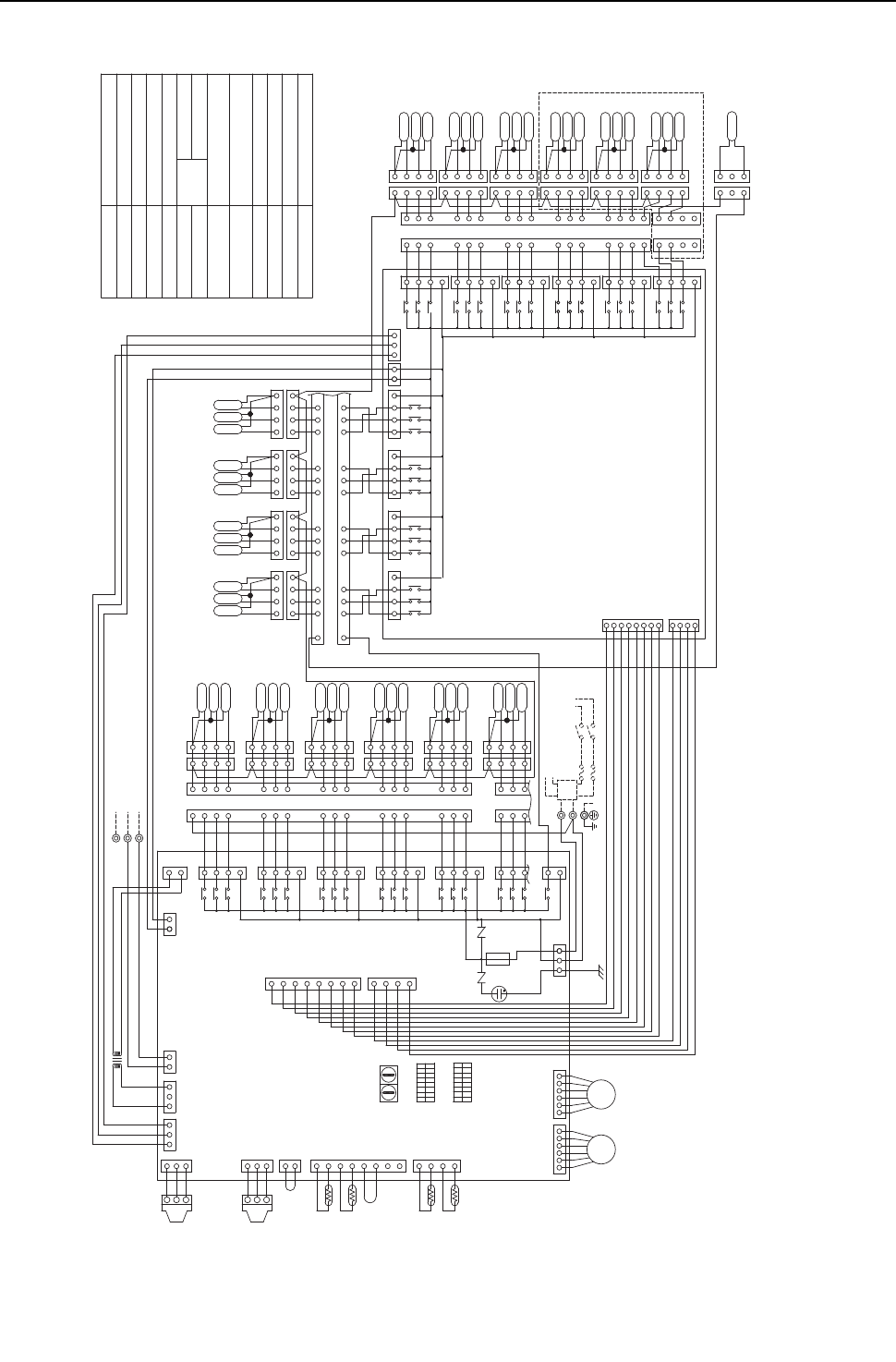
[ V Electrical Wiring Diagram ]
- 114 -
HWE09080 GB
(4) CMB-P1013,1016NU-G models
ZNR01 ZNR02
L1
L2
TB01
M1
M2
TB02
S(SHIELD)
CN32
CN33(Red)
CN34(Black)
CN35(Blue)
CN36(Green)
CN31(Yellow)
CN30(Black)
CN29(Green)
CN28(Blue)
CN27(Red)
(Red)
(Blue) (Yellow)
CN07 CN05
CN13
LEV1LEV3
X21
3
1
21
CNVCC1
3
CNVCC2
312
CONT.B
CN39
13
135
CN12
CNOUT3
CNOUT1
13
1
2
3
8
7
6
5
4
3
2
1
4
CNOUT2
CNOUT4
6
54
3
2
16
54
3
2
1
1
2
3
CNP1
1
2
3
CNP3
2
1
1
2
3
4
5
6
7
8
4
3
2
1
12321
CN03 CN02
CN10
CN11
TH11
TH12
TH15
TH16
TR
CN38 CN26
3
1
CNTR
4
1
2
3
4
5
6
7
8
3
2
1
PS1
PS3
CN44(Yellow)
CN45(Green)
CN41(Green)
CN43(Red)
(Yellow)
SV1B
SV1A
SV1C
5
6
7
8
9
10
11
12
13
14
15
16
3
2
4
8
9
10
11
12
13
3
2
4
5
6
7
14
15
16
4
3
2
SV2C
SV2A
SV2B
SV3C
SV3A
SV3B
SV4C
SV4A
SV4B
SV5B
SV5A
SV5C
4
3
2
1
4
3
2
1
4
3
2
1
4
3
2
1
4
3
2
4
3
2
1
4
3
2
1
4
3
2
1
4
3
2
1
SV6B
SV6A
SV6C
1
2
3
4
1
2
3
4
33
2
1
2
1
X35
X11
X12
X34
X9
X10
X33
X7
X8
X32
X5
X6
X31
X3
X4
X30
X1
X2
5
3
1
7
5
3
1
7
5
3
1
7
5
3
1
7
5
3
1
7
5
3
1
11 1
1
SV7A
SV7B
SV7C
SV8B
SV8A
SV8C
SV9B
SV9A
SV9C
SV10B
SV10A
SV10C
16
16
131415 9
101112 5
6
78 4
4
5
6
87
9
12 11 10
15 14 13
1
2
3
41
2
3
41
2
3
41
2
3
4
1
2
3
41
2
3
41
2
3
41
2
3
4
753133
X14
X13
X36
X37
X15
X16
X38
X39
X17
X19
X18
X20
753175317531
CN40
SVM1
2
3
2
1
3
1
REL.B
4
5
6
8
9
7
10
12
11
13
15
14
16
3
4
2
1
SV11B
SV11A
SV11C
1
3
2
8
9
10
11
12
13
3
2
4
1
5
6
7
14
15
16
4
3
2
1
SV12C
SV12A
SV12B
SV13C
SV13A
SV13B
SV14C
SV14A
SV14B
SV15B
SV15A
SV15C
4
3
2
1
4
3
2
1
4
3
2
1
4
3
2
1
4
3
2
1
4
3
2
1
4
3
2
1
4
3
2
1
4
3
2
1
SV16B
SV16A
SV16C
1
2
3
4
1
2
3
4
3
4
2
1
X51
X55
X56
X52
X53
X57
X54
7
7
5
3
1
7
5
3
1
X45
X42
X43
X40
X44
X48
X47
X46
X50
X49
CN42
5
7
7
5
3
1
7
5
3
1
5
3
1
3
X41
1
Solenoid valve
SVM1
CONT.B
Terminal block
(for Transmission)
TB02
Terminal block
(for power source)
TB01
Solenoid valve
Expansion valve
Thermistor sensor
Transformer
Name
Symbol
SV1~16A,B,C
TR
TH11,12,15,16
LEV1,3
PS1,3 Pressure sensor
Terminal
T1~16
F01 Fuse AC250V 6.3A F
Note:1.TB02 is transmission
terminal block.
Never connect power
line to it.
2.The initial set values
of switch on CONT.B
are as follows.
SW1:0
SW2:0
INDOOR UNIT
GG
PULL BOX
FUSE(15A) BREAKER(15A)
POWER SUPPLY
~208V-230V
60Hz
TO NEXT
Indoor/outdoor (heat source)
Transmission line
2
2
1
3
1
3
T1
T5
T4
T3
T2
T6
T10
T9 T8 T7
T11
T15
T14
T13
T12
T16
1
ON
SW4
8
OFF
SW5
OFF
ON
81
DSA
(Blue)
(Yellow) (Red)
(Red)
(Black)
10 1
SW1SW2
F01
250VAC
6.3A F
CMB-P1016NU-G ONLY
Relay
REL.B
BC controller
Circuit
board
(Symbol explanation)
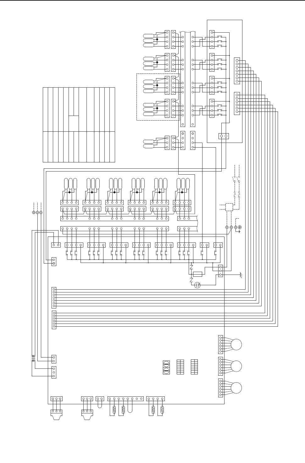
[ V Electrical Wiring Diagram ]
- 115 -
HWE09080 GB
(5) CMB-P108,1010NU-GA models
Note:1.TB02 is transmission
terminal block.
Never connect power
line to it.
2.The initial set values
of switch on CONT.B
are as follows.
SW1:0
SW2:0
F01 Fuse AC250V 6.3A F
T1~10 Terminal
Solenoid valve
SVM1,2
CONT.B
Terminal block
(for Transmission)
TB02
Terminal block
(for power source)
TB01
Solenoid valve
Expansion valve
Thermistor sensor
Transformer
Name
Symbol
SV1~10A,B,C
TR
TH11,12,15,16
LEV1~3
PS1,3 Pressure sensor
654321
CN53
654321123456
CN51
(Yellow)
CN03
TB01
L2
L1
CN36(Green)
CN30(Black)
CN31(Yellow)
CN29(Green)
CN28(Blue)
CN27(Red)
(Red)
CNTR
ZNR01 ZNR02
M1
M2
TB02
S(SHIELD)
CN06 CN05
CN07
CN13
CNP1
LEV2
123456
1
3
CN26
CN38
31
CN12
53
1
76543211234567
CN50
PS3
PS1
TR
TH16
TH15
TH12
TH11
CN11
CN10
CN02
12321
1
2
3
4
8
7
6
5
4
3
2
1
1
2
CNP3
3
2
1
3
2
1
LEV1LEV3
123456
123456
CONT.B
SV6B
SV6A
SV6C
1
2
3
4
1
2
3
4
33
2
1
2
1
16
15
14
7
6
5
13
12
11
10
9
8
16
15
14
7
6
5
10
9
8
13
12
11
4
4
4
4
3
3
3
3
2
2
2
2
1
1
1
1
SV5C
SV5A
SV5B
SV4B
SV4A
SV4C
SV3B
SV3A
SV3C
SV2B
SV2A
SV2C
2
3
4
1
2
3
4
2
3
4
2
3
4
1
1
1
7
5
3
1
7
5
3
1
7
5
3
1
7
5
3
1
7
5
3
1
7
X4
X3
X31
X6
X5
X32
X8
X7
X33
X10
X9
X34
X12
X11
X35
1
4
2
3
1
4
2
3
4
3
2
1
SV1C
SV1A
SV1B
1
2
3
4
5
3
1
X2
X1
X30
X60
X21
CN46(Yellow)
3
1
3
1
3
1
CN33(Red)
CN34(Black)
CN35(Blue)
CN39
REL.B
CN52
1234567
1
2
3
4
1
2
3
4
1
2
3
4
1
2
3
4
1
2
3
4
1
2
3
4
1
2
3
4
1
2
3
4
SV7B
SV8B
SV9B
SV10B
SV7A
SV8A
SV9A
SV10A
SV7C
SV8C
SV9C
SV10C
131415 101112 978 654
4
87 65
12 11 10 9
15 14 13
16
16
CN32
X14
X13
X36
X37
X15
X16
X18
X17
X38
X39
X19
X20
571751753175133 3
1
2
34
41
2
3
1
2
3
1
2
3
SVM1
SVM2
60Hz
~208V-230V
POWER SUPPLY
BREAKER(15A)
PULL BOX
FUSE(15A)
TO NEXT INDOOR UNIT
G
G
Indoor/outdoor (heat source)
Transmission line
2
1
3
2
3
1
T6
T2
T3
T4
T5
T1
T7
T8T9
T10
81
OFF
ON
SW4
SW5
OFF
ON
81
Relay
REL.B
BC controller
Circuit
board
(Symbol explanation)
CMB-P1010NU-GA ONLY
DSA
(Blue) (Red)
(Yellow)
(Red)
(Black)
SW2 SW1
110
F01
250VAC
6.3A F
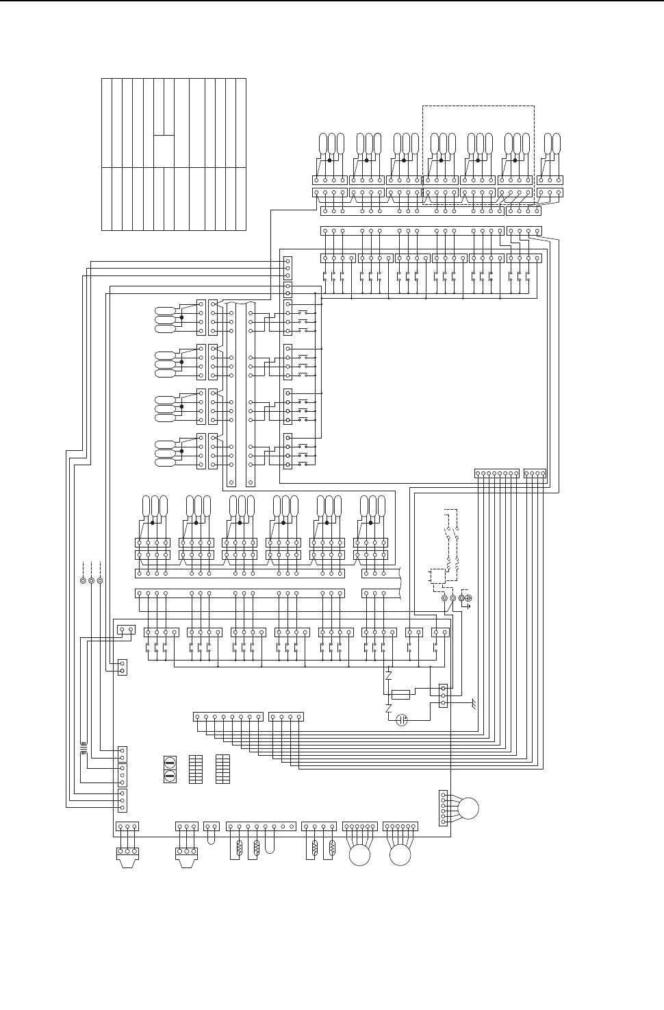
[ V Electrical Wiring Diagram ]
- 116 -
HWE09080 GB
(6) CMB-P1013,1016NU-GA models
CNTR
(Red)
CN41(Green)
CN40
(Yellow)
CN34(Black)
CN33(Red)
CN35(Blue)
ZNR01 ZNR02
CN06
54
3
2
1
LEV2
CN07
CN13
CNP1
(Blue)
CNVCC1
(Yellow)
CN03
M1
M2
TB02
S(SHIELD)
6
54
3
2
1
LEV3
213
CNVCC2
312
CONT.B
CN39
13
CNOUT3
CNOUT1
13
1
2
3
1
2
3
CNP3
2
1
1
2
3
4
5
6
7
8
4
3
2
1
12321
CN02
CN10
CN11
TH11
TH12
TH15
TH16
TR
CN38 CN26
3
1
4
1
2
3
4
5
6
7
8
3
2
1
PS1
PS3
X45
X42
X43
X40
X44
X47
X46
CN42
X41
SV1B
SV1A
SV1C
5
6
7
8
9
10
11
12
13
14
15
16
3
2
4
8
9
10
11
12
13
3
2
4
5
6
7
14
15
16
4
3
2
SV2C
SV2A
SV2B
SV3C
SV3A
SV3B
SV4C
SV4A
SV4B
SV5B
SV5A
SV5C
4
3
2
1
4
3
2
1
4
3
2
1
4
3
2
1
4
3
2
4
3
2
1
4
3
2
1
4
3
2
1
4
3
2
1
SV6B
SV6A
SV6C
1
2
3
4
1
2
3
4
33
2
1
2
1
CN31(Yellow)
CN30(Black)
CN29(Green)
CN28(Blue)
CN27(Red)
X35
X11
X12
X34
X9
X10
X33
X7
X8
X32
X5
X6
X31
X3
X4
X30
X1
X2
7
5
3
1
7
5
3
1
7
5
3
1
7
5
3
1
7
5
3
1
7
5
3
1
11 1
1
SV7A
SV7B
SV7C
SV8B
SV8A
SV8C
SV9B
SV9A
SV9C
SV10B
SV10A
SV10C
16
16
131415 9
101112 5
6
78 4
4
5
6
87
9
12 11 10
15 14 13
1
2
3
41
2
3
41
2
3
41
2
3
4
1
2
3
41
2
3
41
2
3
41
2
3
4
CN32
753133
X14
X13
X36
X37
X15
X16
X38
X39
X17
X19
X18
X20
753175317531
1
CN36(Green)
X21
CN45(Green)
CN44(Yellow)
CN43(Red)
REL.B
4
5
6
8
9
7
10
12
11
13
15
14
16
3
4
2
1
SV11B
SV11A
SV11C
1
3
2
8
9
10
11
12
13
3
2
4
1
5
6
7
14
15
16
4
3
2
1
SV12C
SV12A
SV12B
SV13C
SV13A
SV13B
SV14C
SV14A
SV14B
SV15B
SV15A
SV15C
4
3
2
1
4
3
2
1
4
3
2
1
4
3
2
1
4
3
2
1
4
3
2
1
4
3
2
1
4
3
2
1
4
3
2
1
SV16B
SV16A
SV16C
1
2
3
4
1
3
4
3
4
2
1
X51
X55
X56
X52
X53
X57
X54
7
7
5
3
1
7
5
3
1
X48
X50
X49
5
7
7
5
3
1
7
5
3
1
5
3
1
3
1
SVM2
SVM1
3
22
3
11
2
CN05
6
54
3
2
1
LEV1
L2
L1
TB01
135
CN12
1
2
3
8
7
6
5
4
3
2
1
4
CNOUT2
CNOUT4
3
3
1
CN46(Yellow)
X60
CONT.B
Terminal block
(for Transmission)
TB02
Terminal block
(for power source)
TB01
Solenoid valve
Expansion valve
Thermistor sensor
Transformer
Name
Symbol
SV1~16A,B,C
TR
TH11,12,15,16
LEV1~3
PS1,3 Pressure sensor
SVM1,2
T1~16 Terminal
Solenoid valve
F01 Fuse AC250V 6.3A F
Note:1.TB02 is transmission terminal
block.Never connect power line
to it.
2.The initial set values of switch
on CONT.B are as follows.
SW1:0
SW2:0
6
Indoor/outdoor (heat source)
Transmission line
2
2
1
3
1
3
T1
T5
T4
T3
T2
T6
T10
T9 T8 T7
T11
T15
T14
T13
T12
T16
PULL BOX
FUSE(15A) BREAKER(15A)
INDOOR UNIT
TO NEXT
POWER SUPPLY
~208V-230V
60Hz
GG
1
ON
SW4
8
OFF
SW5
OFF
ON
81
(Blue)
DSA
(Blue)
(Yellow)
(Red)
(Black)
10 1
SW1SW2
CMB-P1016NU-GA ONLY
(Red)
F01
250VAC
6.3A F
Relay
REL.B
BC controller
Circuit
board
(Symbol explanation)
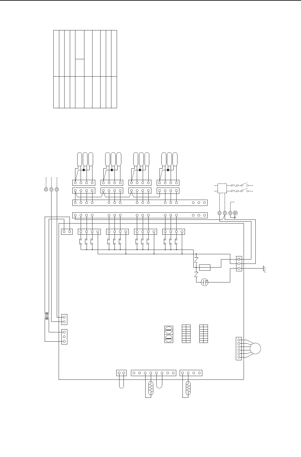
[ V Electrical Wiring Diagram ]
- 117 -
HWE09080 GB
(7) CMB-P104NU-GB model
ZNR02
ZNR01
CN29(Green)
CN28(Blue)
CN27(Red)
CNTR
(Red)
CN07
L1
L2
TB01
CN13
CN03
M1
M2
S(SHIELD)
TB02
X33
X7
X8 1
3
5
7
1
4
3
2
1
14
16
15
SV4A
SV4C
SV4B
11
12
13
14
15
16
11
12
13
4
3
2
11
11
X32
X5
X6
X31
X3
X4
X30
X1
X2 1
3
5
7
1
3
5
7
1
3
5
7
SV1B
SV1A
SV1C
5
6
7
8
9
4
3
2
4
3
2
1
4
3
2
1
2
3
4
6
5
7
3
4
2
SV2A
SV2C
SV3C
SV2B
SV3B
SV3A
3
4
1
2
10
3
2
4
8
9
10
4
3
2
1
LEV3
123456
TH15
TH12
CN11
CN10
12321
1
2
3
4
8
7
6
5
4
3
2
1
1
2
CN02
CONT.B
35
1
CN12
1
3
CN26
TR
Fuse AC250V 6.3A F
F01
Terminal
T1~4
Terminal block
(for Transmission)
TB02
Terminal block
(for power source)
TB01
Solenoid valve
SV1~4A,B,C
Expansion valve
Thermistor sensor
Transformer
Name
Symbol
TR
TH12,15
LEV3
CONT.B
Note:1.TB02 is transmission
terminal block.
Never connect power
line to it.
2.The initial set values
of switch on CONT.B
are as follows.
SW1:0
SW2:0
GG
FUSE(15A)
BREAKER(15A)
POWER SUPPLY
~208V-230V
60Hz
TO NEXT INDOOR UNIT
PULL BOX
Indoor/outdoor (heat source)
Transmission Line
T4
T1
T3
T2
8
1
ON
SW4
8
OFF
SW5
1
OFF
ON
DSA
(Yellow)
(Red)
(Yellow)
F01
250VAC
6.3A F
10 1
SW1SW2
Circuit
board
(Symbol explanation)
BC controller
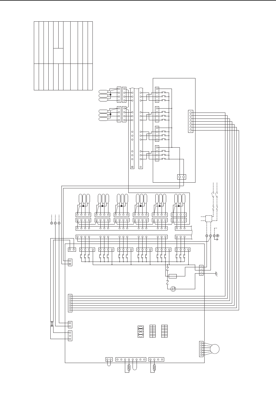
[ V Electrical Wiring Diagram ]
- 118 -
HWE09080 GB
(8) CMB-P108NU-GB model
CN31(Yellow)
CN33(Red)
CN34(Black)
CN35(Blue)
CN30(Black)
CN29(Green)
CN28(Blue)
CN27(Red)
TB01
L1
L2
ZNR02
ZNR01
CN07
CN13
(Red)
M1
M2
S(SHIELD)
TB02
CN12
31571357135713 75
X20
X19
X39
X38
X17
X18
X16
X15
X37
X36
X13
X14
CN32
16
16 131415 9
101112 5
6
78 4
4
5
6
87
9
12 11 10
15 14 13
SV8C
SV7C
SV8A
SV7A
SV8B
SV7B
43214321
43214321
X30
X1
X2 1
3
54
3
2
1
SV1B
SV1A
SV1C
1
2
3
4
3
2
4
1
3
2
4
1
X35
X11
X12
X34
X9
X10
X33
X7
X8
X32
X5
X6
X31
X3
X4
7
1
3
5
7
1
3
5
7
1
3
5
7
1
3
5
7
1
3
5
7
1
1
1
4
3
2
4
3
2
4
3
2
1
4
3
2
SV2C
SV2A
SV2B
SV3C
SV3A
SV3B
SV4C
SV4A
SV4B
SV5B
SV5A
SV5C
1
1
1
1
2
2
2
2
3
3
3
3
4
4
4
4
11
12
13
8
9
10
5
6
7
14
15
16
8
9
10
11
12
13
5
6
7
14
15
16
1
2
1
2
33 4
3
2
1
4
3
2
1
SV6C
SV6A
SV6B
7654321
CN39
3
1
CN52
CONT.B
6
54
3
2
1
LEV3
2
1
1
2
3
4
5
6
7
8
4
3
2
1
12321
CN03 CN02
CN10
CN11
TH12
TH15
TR
CN50
7654321
135
13
CN38 CN26
3
1
CNTR
REL.B
F01 Fuse AC250V 6.3A F
Terminal
T1~8
CONT.B
Terminal block
(for Transmission)
TB02
Terminal block
(for power source)
TB01
Solenoid valve
Expansion valve
Thermistor sensor
Transformer
Name
Symbol
SV1~8A,B,C
TR
TH12,15
LEV3
Note:1.TB02 is transmission
terminal block.
Never connect power
line to it.
2.The initial set values
of switch on CONT.B
are as follows.
SW1:0
SW2:0
G
60Hz
~208V-230V
POWER SUPPLY
BREAKER(15A)
FUSE(15A)
PULL BOX
TO NEXT INDOOR UNIT
G
Indoor/outdoor (heat source)
Transmission line
T8 T7
T1
T5
T4
T3
T2
T6
18
ON
OFF
SW5
SW4
ON
OFF
18
F01
250VAC
6.3A F
DSA
(Yellow)
(Red)
Relay
REL.B
BC controller
Circuit
board
(Symbol explanation)
10 1
SW1SW2
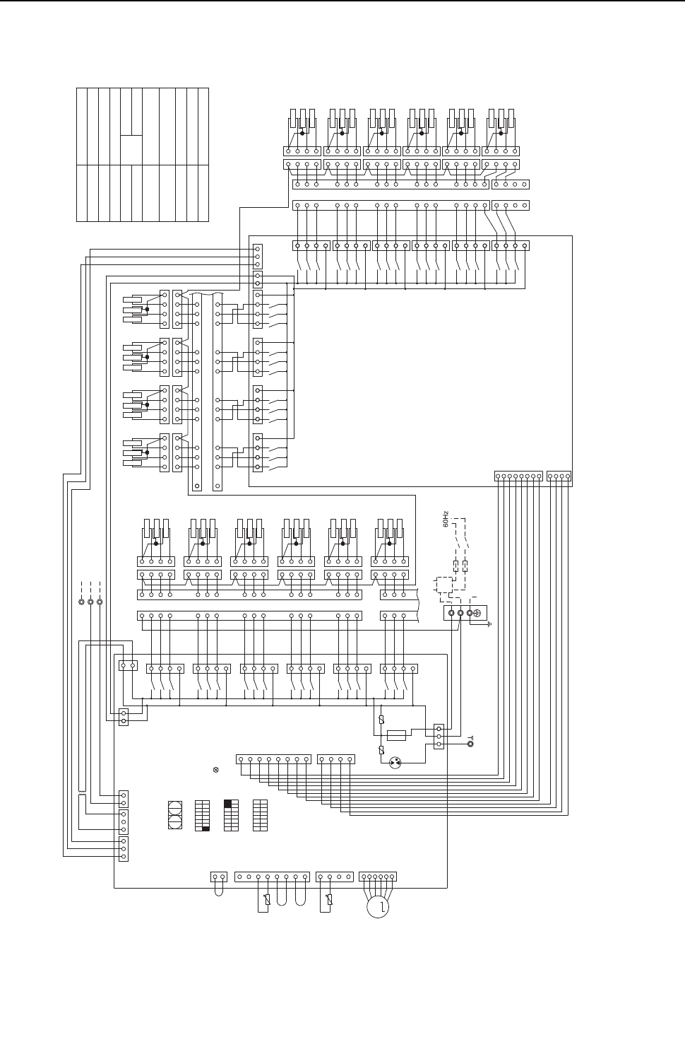
[ V Electrical Wiring Diagram ]
- 119 -
HWE09080 GB
(9) CMB-P1016NU-HB model
L2
L1
GG
Note:1.TB02 is transmission terminal
block.Never connect power line
to it.
2.The initial set values of swith
on CONT.B are as follows.
SW1:0
SW2:0
TB01
SV16B
SV16A
SV16C
SV15B
SV15A
SV15C
SV14B
SV14A
SV14C
SV13B
SV13A
SV13C
SV12B
SV12A
SV12C
SV11B
SV11A
SV11C
SV7B
SV7A
SV7C
SV8B
SV8A
SV8C
SV9B
SV9A
SV9C
SV10B
SV10A
SV10C
SV6B
SV6A
SV6C
SV5B
SV5A
SV5C
SV4B
SV4A
SV4C
SV3B
SV3A
SV3C
SV2B
SV2A
SV2C
SV1C
SV1A
SV1B
M1
M2
REL.B
CONT.B
4
3
2
1
2
3
44
3
2
1
1
3
44
3
2
1
4
4
3
1
2
1
3
2
4
3
2
1
1
2
3
4
4
3
2
11
2
3
4
3
4
2
1
16
13
15
14
16
3
4
2
1
13
14
15
7
1
3
5
7
X57
X55
X56
CN45(Green)
X54
2
1
4
3
2
1
11
8
9
7
10
12
11
8
9
10
11
12
7
4
5
6
3
2
3
2
4
5
6
7
5
3
1
3
5
7
1
3
5
7
1
5
3
X52
X53
CN44(Yellow)
X51
X49
X50
CN43(Red)
X48
X46
X47
CN42
X45
X43
X44
CN41(Green)
7
5
3
1
X42
X40
X41
CN40
(Yellow)
1
(Blue)
312
3
CNVCC2
X14
X13
X36
7531
CN32
CN39
1357
X37
X15
X16
CN33(Red)
1357
X38
X17
X18
CN34(Black)
1357
X39
X19
X20
CN35(Blue)
54
4
5
16
16
131415 9
101112 6
78
6
87
9
12 11 10
15 14 13
1
2
3
4
4321
4321
1
2
3
4
4321
1
2
3
4
4321
1
2
3
4
1
2
3
8
7
6
5
4
3
2
1
4
CNOUT2
CNOUT4
1
2
3
4
4
3
2
1
4
3
2
1
1
2
3
4
1
2
3
44
3
2
1
1
2
3
44
3
2
1
1
2
3
4
4
3
2
1
1
2
3
44
3
2
1
TO NEXT
INDOOR UNIT
PULL BOX
FUSE(15A) BREAKER(15A)
POWER SUPPLY
~208V-230V
33
2
1
2
1
11
5
6
7
8
9
10
11
12
13
14
15
16
3
2
4
8
9
10
11
12
13
3
2
4
5
6
7
14
15
16
S(SHIELD)
TB02 Indoor/outdoor
Transmission line
CN07
(Yellow)
1
2
3
6
5
4
TH15
1
2
3
4
CN11
TH12
1
1
2(Red)
CN13
2
3
CN10
4
5
6
7
8
SW6
18
SW5
SW4
18
ON
OFF
ON
OFF
ON
OFF
81
SW1SW2
10 1
CNOUT1
1
2
3
4
5
6
7
8
1
4
3
2
CNOUT3
F01
250VAC
6.3A F
ZNR01 ZNR02
CN12
135
7
5
X35
X11
3
1
X12
CN31(Yellow)
X09
X34 7
5
3
1
X10
CN30(Black)
7
1
3
5
X33
X07
X08
CN29(Green)
7
5
3
1
X32
X05
X06
CN28(Blue)
X04
X03
X31 7
5
3
1
CN27(Red)
1
3
5
7
X30
X01
X02
CN26
1
3
CNTR(Red)
31
CN38
TR
11132 32 2
CN02
CN03
(Yellow)
CNVCC1
(Blue)
Terminal
T1~T16
Solenoid valve
SV1~16A,B,C
TB02 Terminal block
(for Transmission)
Terminal block
(for power source)
TB01
CONT.B
REL.B
TR
TH12,15
LEV3
Symbol
Name
Transformer
Thermister sensor
Expansion valve
Circuit
board
Relay
BC controller
(
Symbol explanation
)
T1
T2
T3
T4
T5
T6
T11
T12
T13
T14
T15
T16
T10
T9 T8 T7
Fuse AC250V 6.3A F
F01
t°
t°
DSA
UU
LD1:CPU in
operation
M
LEV3
33
7
5
3
1
1
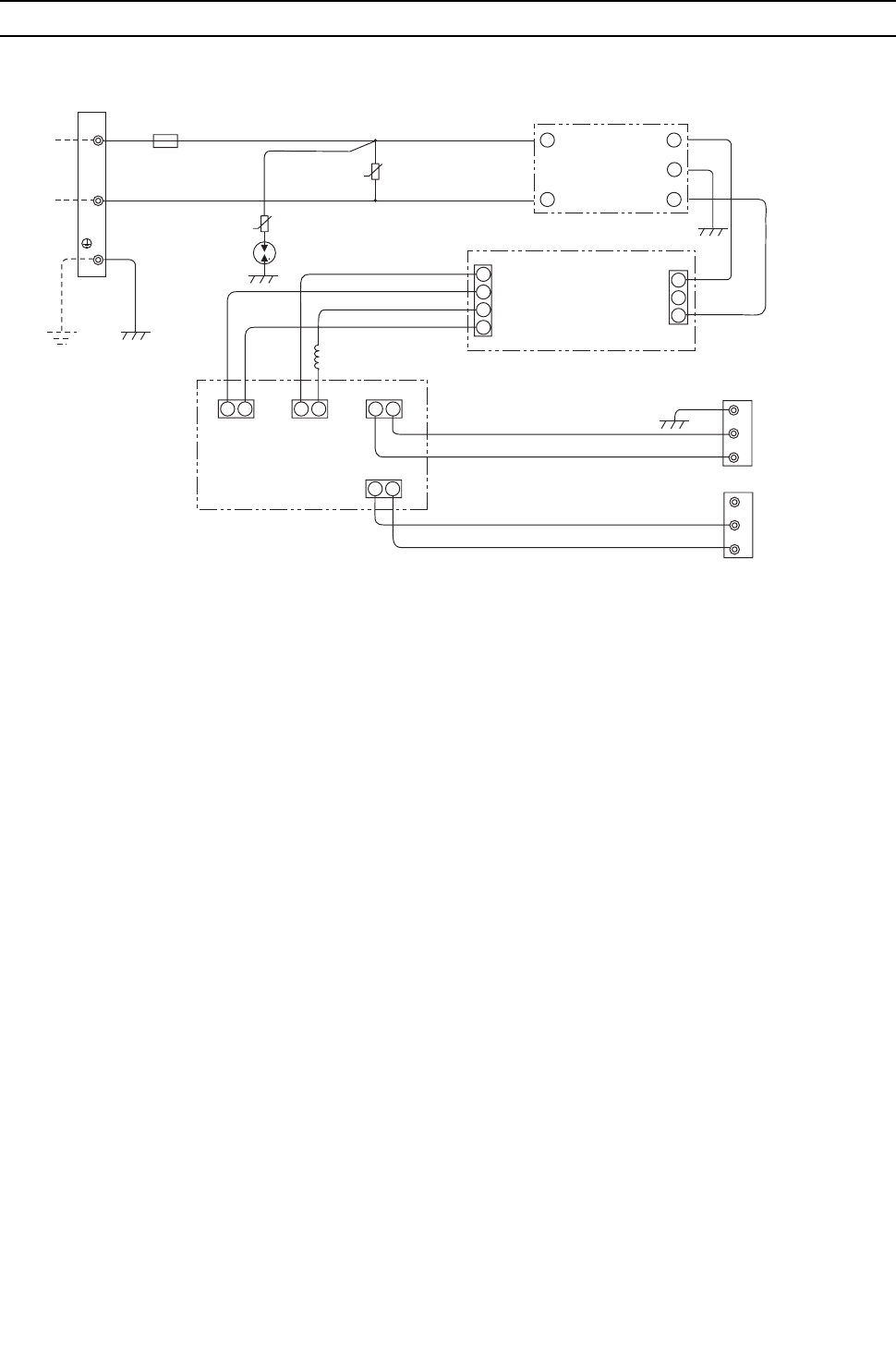
[ V Electrical Wiring Diagram ]
- 120 -
HWE09080 GB
[3] Electrical Wiring Diagram of Transmission Booster
100V/200VAC
Terminal block for power supply
(TB1)
LRed Red Red
White
Green
250V 5A
Grounding
Red
Red
Red
U
U
White
White White
White
White
White BlueRedRed
DSA
White
White
Blue
Red
Red
Red
Red
Varistor
Varistor
Noise filter
Stabilized power supply
4
3
2
1
1
2
3
CN2 CN1
Black
Black
Black
Black
Green/Yellow
1
2
3
E
4
Choke coil
12
CN3
1212
CN4
CN2
1
2
CN1
Electronic control board
Black
White
Red
Red
Black
S
B
A
S
B
A
Terminal block 2 for
transmission line (TB3)
Expanded (indoor unit) side
Terminal block 1 for
transmission line (TB2)
Expanded (heat source unit) side

- 121 -
HWE09080 GB
VI
Refrigerant Circuit
[1] Refrigerant Circuit Diagram ........................................................................................... 123
[2] Principal Parts and Functions ........................................................................................ 126

- 122 -
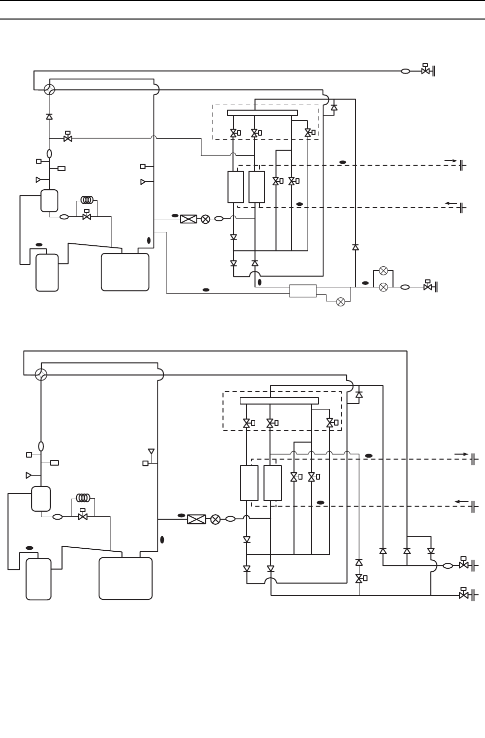
[ VI Refrigerant Circuit ]
- 123 -
HWE09080 GB
VI Refrigerant Ci rcuit
[1] Refrigerant Circuit Diagram
1. Heat source unit
(1) PQHY-P72, P96, P120 models
(2) PQRY-P72, P96, P120 models
63HS1
O/S
TH4 TH5
TH3
CJ2
SV1a
CP1
CJ1
21S4a
ST3
Acc
ST17
63H1
Comp
CV8
CV1
CV6a
TH8
TH7
SV7bSV7a
CV4a
CV3a
CV7a
BV2
SV4a SV4b
SV4d
Solenoid valve block
THINV
Component
cooler heat
exchanger
LEVINV
ST13
Water circuit
SV9
63LS
ST2
LEV1
HIC
TH2
TH6
LEV2a
LEV2b
BV1
ST1
63HS1
O/S
TH4 TH5
CJ2
SV1a
CP1
CJ1
21S4a
ST3
Acc
ST17
63H1
Comp
ST1
63LS
CV8
CV6a
TH8
TH7
SV7bSV7a
SV9
CV4a
CV2aCV3a
CV7a
CV5a
BV1
BV2
SV4a SV4b
SV4d
Solenoid valve block
THINV
Component cooler
heat exchanger
LEVINV
ST13
Water circuit
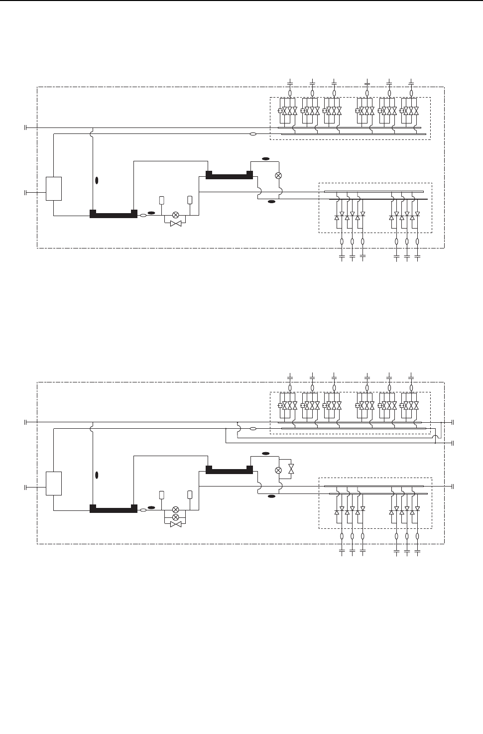
[ VI Refrigerant Circuit ]
- 124 -
HWE09080 GB
2. BC controller
(1) CMB-P104 - P1010NU-G
(2) CMB-P108, P1013, P1016NU-GA (main)
TH15
TH12
LEV3
LEV1 TH16
PS3PS1
TH11
SVM1
Gas/Liquid
separator
Check valve block
Solenoid valve block
TH15
TH12
LEV3 SVM2
LEV1
LEV2
TH16
PS3PS1
TH11
SVM1
Gas/Liquid
separator
Check valve block
Solenoid valve block
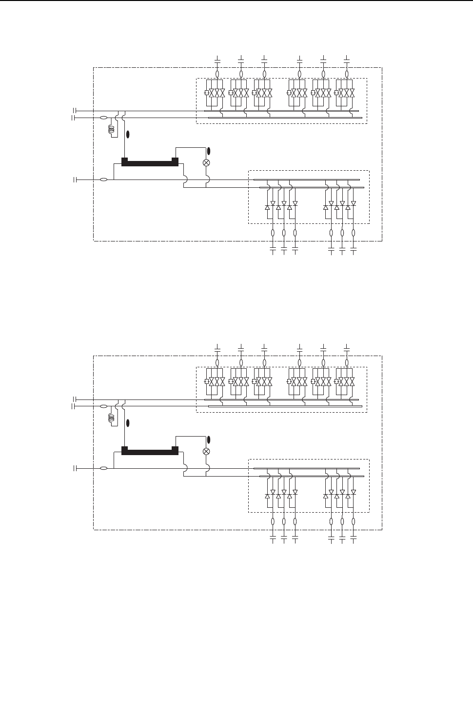
[ VI Refrigerant Circuit ]
- 125 -
HWE09080 GB
(3) CMB-P104, P108NU-GB (sub)
(4) CMB-P1016NU-HB (sub)
TH15
TH12
HIC-C
CP
LEV3
Check valve block
Solenoid valve block
TH15
TH12
HIC-C
CP
LEV3
Check valve block
Solenoid valve block
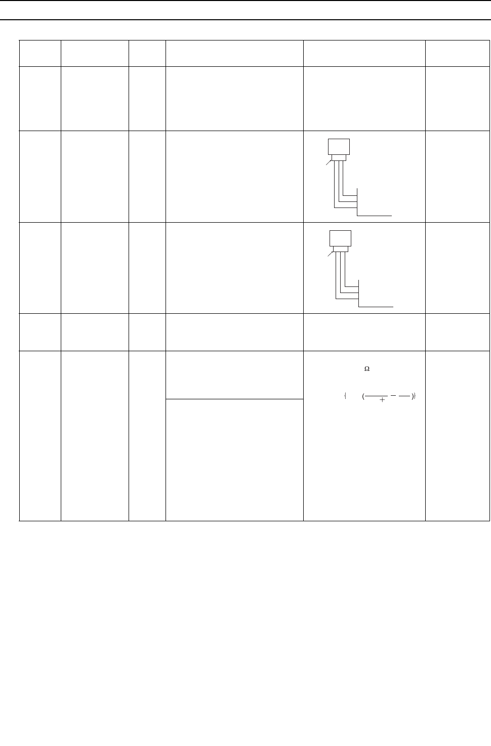
[ VI Refrigerant Circuit ]
- 126 -
HWE09080 GB
[2] Principal Parts and Functions
1. Heat source unit
Part
name
Symbols
(functions) Notes Usage Specifications Check method
Com-
pressor
MC1
(Comp1)
Adjusts the amount of circulating
refrigerant by adjusting the operat-
ing frequency based on the oper-
ating pressure data
Low-pressure shell scroll
compressor
Wirewound resistance
20°C[68°F] :
0.268ohm(THMU)
0.981ohm(YHMU)
High
pres-
sure
sensor
63HS1 1) Detects high pressure
2) Regulates frequency and pro-
vides high-pressure protec-
tion
Low
pres-
sure
sensor
63LS 1) Detects low pressure
2) Provides low-pressure pro-
tection
Pres-
sure
switch
63H1 1) Detects high pressure
2) Provides high-pressure pro-
tection
4.15MPa[601psi] OFF setting
Thermis-
tor
TH4
(Discharge)
1) Detects discharge air temper-
ature
2) Provides high-pressure pro-
tection
Degrees Celsius Resistance
check
0°C[32°F] :698kohm
10°C[50°F] :413kohm
20°C[68°F] :250kohm
30°C[86°F] :160kohm
40°C[104°F] :104kohm
50°C[122°F] : 70kohm
60°C[140°F] : 48kohm
70°C[158°F] : 34kohm
80°C[176°F] : 24kohm
90°C[194°F] :17.5kohm
100°C[212°F] :13.0kohm
110°C[230°F] : 9.8kohm
Pressure
0~4.15 MPa [601psi]
Vout 0.5~3.5V
0.071V/0.098 MPa [14psi]
Pressure [MPa]
=1.38 x Vout [V]-0.69
Pressure [psi]
=(1.38 x Vout [V] - 0.69) x 145
GND (Black)
Vout (White)
Vcc (DC5V) (Red)
Con-
nector
63HS1
1
123
2
3
Pressure
0~1.7 MPa [247psi]
Vout 0.5~3.5V
0.173V/0.098 MPa [14psi]
Pressure [MPa]
=0.566 x Vout [V] - 0.283
Pressure [psi]
=(0.566 x Vout [V] - 0.283) x 145
GND (Black)
Vout (White)
Vcc (DC5V) (Red)
Con-
nector
63LS
1
123
2
3
R = 7.465k
120
R = 4057
R =
7.465
25/120
t
4057
273 t
1
393
1
exp
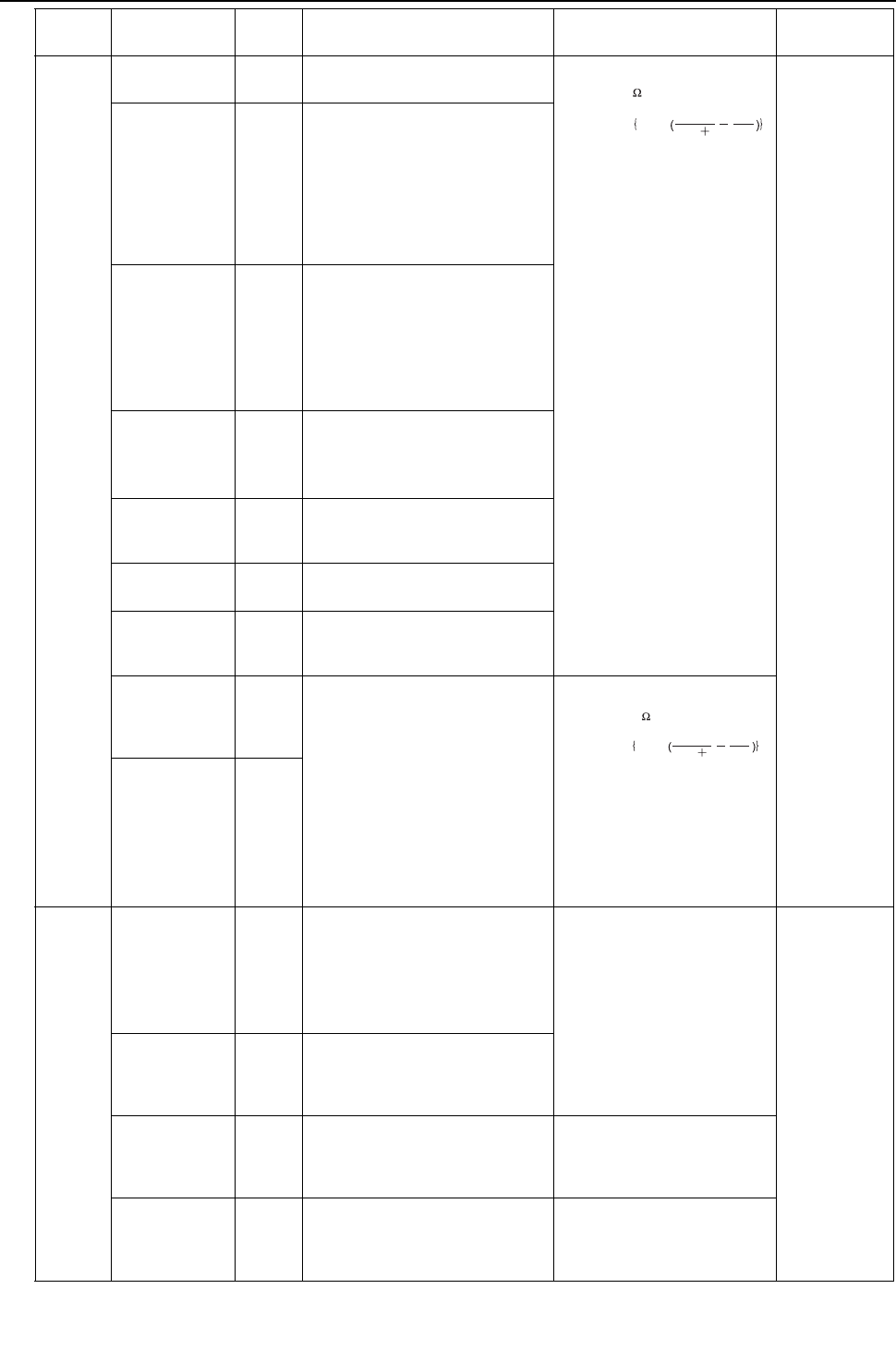
[ VI Refrigerant Circuit ]
- 127 -
HWE09080 GB
Thermis-
tor
TH2 PQHY
only
LEV1 is controlled based on the
TH2, TH3, and TH6 values
Degrees Celsius
0°C[32°F]: 15kohm
10°C[50°F]: 9.7kohm
20°C[68°F]: 6.4kohm
25°C[77°F]: 5.3kohm
30°C[86°F]: 4.3kohm
40°C[104°F]: 3.1kohm
Resistance
check
TH3
(Pipe
temperature)
PQHY
only
Controls defrosting during heating
operation
1) Frequency control
2) LEV1 is controlled according
to the amount of subcool at
the heat exchanger outlet,
which is calculated based on
the HPS data and TH3 value.
TH7
(Water inlet
temperature)
1) Detects water inlet tempera-
ture
2) Protects water heat exchang-
er from high and low temper-
atures
3) Controls water heat exchang-
er
TH8
(Water outlet
temperature)
1) Detects water inlet tempera-
ture
2) Protects water heat exchang-
er from freezing up
TH5 Water heat exchanger is con-
trolled based on the 63LS and
TH5 values.
TH6 PQHY
only
LEV1 is controlled based on the
TH2, TH3, and TH6 values
THINV Determines the LEV that controls
refrigerant flow on the component
cooler
THHS
Inverter
heat sink tem-
perature
Controls inverter cooling fan
based on THHS temperature
Degrees Celsius
0°C[32°F]: 161kohm
10°C[50°F]: 97kohm
20°C[68°F]: 60kohm
25°C[77°F]: 48kohm
30°C[86°F]: 39kohm
40°C[104°F]: 25kohm
THBOX
Control box in-
ternal tempera-
ture detection
Sole-
noid
valve
SV1a
Discharge-suc-
tion
bypass
1) High/low pressure bypass at
start-up and stopping, and
capacity control during low-
load operation
2) High-pressure-rise preven-
tion
AC208 - 230V
Open while being powered/
closed while not being pow-
ered
Continuity
check with a
tester
SV4a - SV4d
Heat
exchanger
capacity control
Controls heat source unit heat ex-
changer capacity
SV7a,7b
Heat
exchanger
capacity control
Controls heat source unit heat ex-
changer capacity
AC208 - 230V
Closed while being powered/
open while not being powered
SV9 High-pressure-rise prevention AC208 - 230V
Open while being powered/
closed while not being pow-
ered
Part
name
Symbols
(functions) Notes Usage Specifications Check method
R = 15k
0
R = 3460
R = 15
0/80
t
3460
273 t
1
273
1
exp
R = 17k
50
R = 4016
R = 17
25/120
t
4016
273 t
1
323
1
exp

[ VI Refrigerant Circuit ]
- 128 -
HWE09080 GB
Heater CH11 Heats the refrigerant in the com-
pressor
Cord heater
1035 ohm 51W
Resistance
check
4-way
valve
21S4a Changeover between heating and
cooling
AC208-230V
Dead: cooling cycle
Live: heating cycle
Continuity
check with a
tester
Elec-
tronic
expan-
sion
valve
LEV1
(for SC control)
PQHY
only
Regulates the amount of bypass
flow from the heat source unit liq-
uid pipe during cooling
12 VDC
Stepping motor driven valve
opening
0-480 pulses (direct driven)
Same as with
the indoor
LEV.
The resistance
values differs
from that of the
LEVs on in-
door unit.
(Refer to the
section on
Troubleshoot-
ing the
LEV(page 310
))
LEV2a
LEV2b
(Refrigerant
flow control
PQHY
only
Controls the refrigerant flow dur-
ing heating
12 VDC
Stepping motor driven valve
opening
1400 pulses
Same as with
the indoor
LEV.
Part
name
Symbols
(functions) Notes Usage Specifications Check method
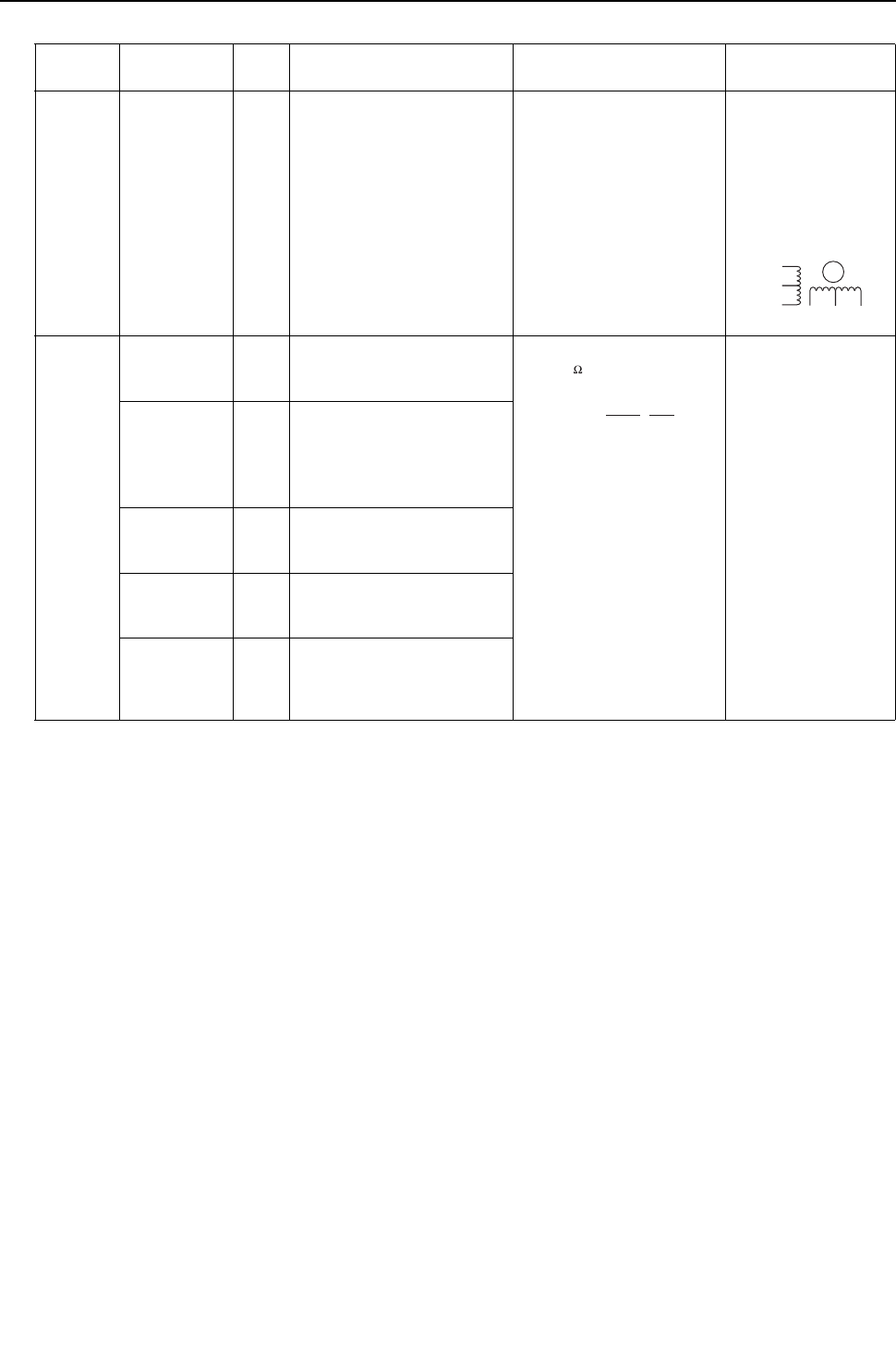
[ VI Refrigerant Circuit ]
- 129 -
HWE09080 GB
2. Indoor Unit
Part
Name
Symbol
(functions) Notes Usage Specification Check method
Linear
expan-
sion valve
LEV 1) Adjusts superheat at the
indoor heat exchanger
outlet during cooling
2) Adjusts subcool at the
heat exchanger outlet of
the indoor unit during
cooling
DC12V
Opening of stepping motor
driving valve 0-(1400) puls-
es
Refer to the section
"Continuity Test with a
Tester".
Continuity between
white, red, and or-
ange.
Continuity between
yellow, brown, and
blue.
Thermis-
tor
TH1
(Suction air
temperature)
Indoor unit control (Thermo)
0°C [32°F]:15kohm
10°C [50°F] :9.7kohm
20°C [68°F]:6.4kohm
25°C [77°F] :5.3kohm
30°C [86°F] :4.3kohm
40°C [104°F] :3.1kohm
Resistance check
TH2
(Pipe temper-
ature)
1) Indoor unit control (Frost
prevention, Hot adjust)
2) LEV control during heat-
ing operation (subcool
detection).
TH3
(Gas pipe
temperature)
LEV control during cooling op-
eration (superheat detection)
TH4
Outdoor air
temperature)
Indoor unit control (Thermo)
Temperature
sensor (In-
door air tem-
perature)
Indoor unit control (Thermo)
Yellow
White
Red
Orange
Brown Blue
M
1
273+t
R
0
=15k
R
0/80
=3460
Rt =
15exp{3460( - )}
1
273
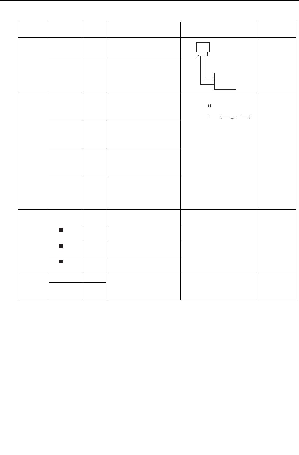
[ VI Refrigerant Circuit ]
- 130 -
HWE09080 GB
3. BC controller
(1) G type
Part name Symbols
(functions)
Part
code Usage Specifications Check method
Pressure
sensor
PS1
(High pres-
sure side)
1) Detects high pressure
2) LEV control
PS3
(Intermedi-
ate pres-
sure)
1) Detects intermediate
pressure
2) LEV control
Thermistor TH11
(Liquid inlet
tempera-
ture)
LEV control
(Liquid level control)
0°C[32°F] : 15kohm
10°C[50°F] :9.7kohm
20°C[68°F] :6.4kohm
25°C[77°F] :5.3kohm
30°C[86°F] :4.3kohm
40°C[104°F] :3.1kohm
TH12
(Bypass
outlet tem-
perature)
LEV control (Superheat)
TH15
(Bypass in-
let tempera-
ture)
LEV control (Superheat)
TH16
(Liquid re-
frigerant
tempera-
ture)
LEV control (Subcool)
Solenoid
valve
SVM1 Opens during cooling and de-
frost modes
AC208-230V
Open while being powered/
closed while not being pow-
ered
Continuity
check with a
tester
SV A Provides refrigerant to indoor
unit in cooling operation
SV B Provides refrigerant to indoor
unit in heating operation
SV C Provides refrigerant to indoor
unit in cooling operation
LEV LEV1 1) Liquid level control
2) Pressure differential con-
trol
DC12V
Opening of a valve driven by a
stepping motor
0-2000 pulses
Same as
indoor LEV
LEV3
Pressure
0~4.15 MPa [601psi]
Vout 0.5~3.5V
0.071V/0.098 MPa [14psi]
Pressure [MPa]
=1.38 x Vout [V]-0.69
Pressure [psi]
=(1.38 x Vout [V] - 0.69) x 145
GND (Black)
Vout (White)
Vcc (DC5V) (Red)
Con-
nector
PS1
1
123
2
3
R = 15k
0
R = 3460
R = 15
0/80
t
3460
273 t
1
273
1
exp
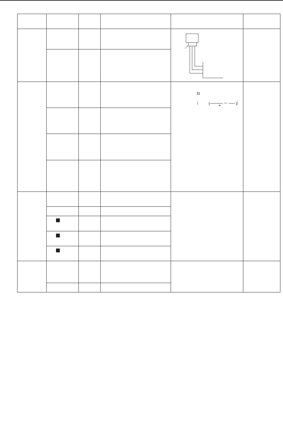
[ VI Refrigerant Circuit ]
- 131 -
HWE09080 GB
(2) GA type
Part name Symbols
(functions)
Part
code Usage Specifications Check method
Pressure
sensor
PS1
(High pres-
sure side)
1) Detects high pressure
2) LEV control
PS3
(Intermedi-
ate pres-
sure)
1) Detects intermediate
pressure
2) LEV control
Thermistor TH11
(Liquid inlet
tempera-
ture)
LEV control
(Liquid level control)
0°C[32°F] : 15kohm
10°C[50°F] :9.7kohm
20°C[68°F] :6.4kohm
25°C[77°F] :5.3kohm
30°C[86°F] :4.3kohm
40°C[104°F] :3.1kohm
TH12
(Bypass
outlet tem-
perature)
LEV control (Superheat)
TH15
(Bypass in-
let tempera-
ture)
LEV control (Superheat)
TH16
(Liquid re-
frigerant
tempera-
ture)
LEV control (Subcool)
Solenoid
valve
SVM1 Opens during cooling and de-
frost modes
AC208-230V
Open while being powered/
closed while not being pow-
ered
Continuity
check with a
tester
SVM2 Pressure differential control
SV A Provides refrigerant to indoor
unit in cooling operation
SV B Provides refrigerant to indoor
unit in heating operation
SV C Provides refrigerant to indoor
unit in cooling operation
LEV LEV1
LEV2
1) Liquid level control
2) Pressure differential con-
trol
DC12V
Opening of a valve driven by a
stepping motor
0-2000 pulses
Same as
indoor LEV
LEV3 Subcool control
Pressure
0~4.15 MPa [601psi]
Vout 0.5~3.5V
0.071V/0.098 MPa [14psi]
Pressure [MPa]
=1.38 x Vout [V]-0.69
Pressure [psi]
=(1.38 x Vout [V] - 0.69) x 145
GND (Black)
Vout (White)
Vcc (DC5V) (Red)
Con-
nector
PS1
1
123
2
3
R = 15k
0
R = 3460
R = 15
0/80
t
3460
273 t
1
273
1
exp

[ VI Refrigerant Circuit ]
- 132 -
HWE09080 GB
(3) GB type
Part name Symbols
(functions)
Part
code Usage Specifications Check method
Thermistor TH12
(Bypass
outlet tem-
perature)
LEV control (Superheat)
0°C[32°F] : 15kohm
10°C[50°F] :9.7kohm
20°C[68°F] :6.4kohm
25°C[77°F] :5.3kohm
30°C[86°F] :4.3kohm
40°C[104°F] :3.1kohm
TH15
(Bypass in-
let tempera-
ture)
LEV control (Superheat)
Solenoid
valve
SV A Provides refrigerant to indoor
unit in cooling operation
AC208-230V
Open while being powered/
closed while not being pow-
ered
Continuity
check with a
tester
SV B Provides refrigerant to indoor
unit in heating operation
SV C Provides refrigerant to indoor
unit in cooling operation
LEV LEV3 Pressure differential control DC12V
Opening of a valve driven by a
stepping motor
0-2000 pulses
Same as
indoor LEV
R = 15k
0
R = 3460
R = 15
0/80
t
3460
273 t
1
273
1
exp
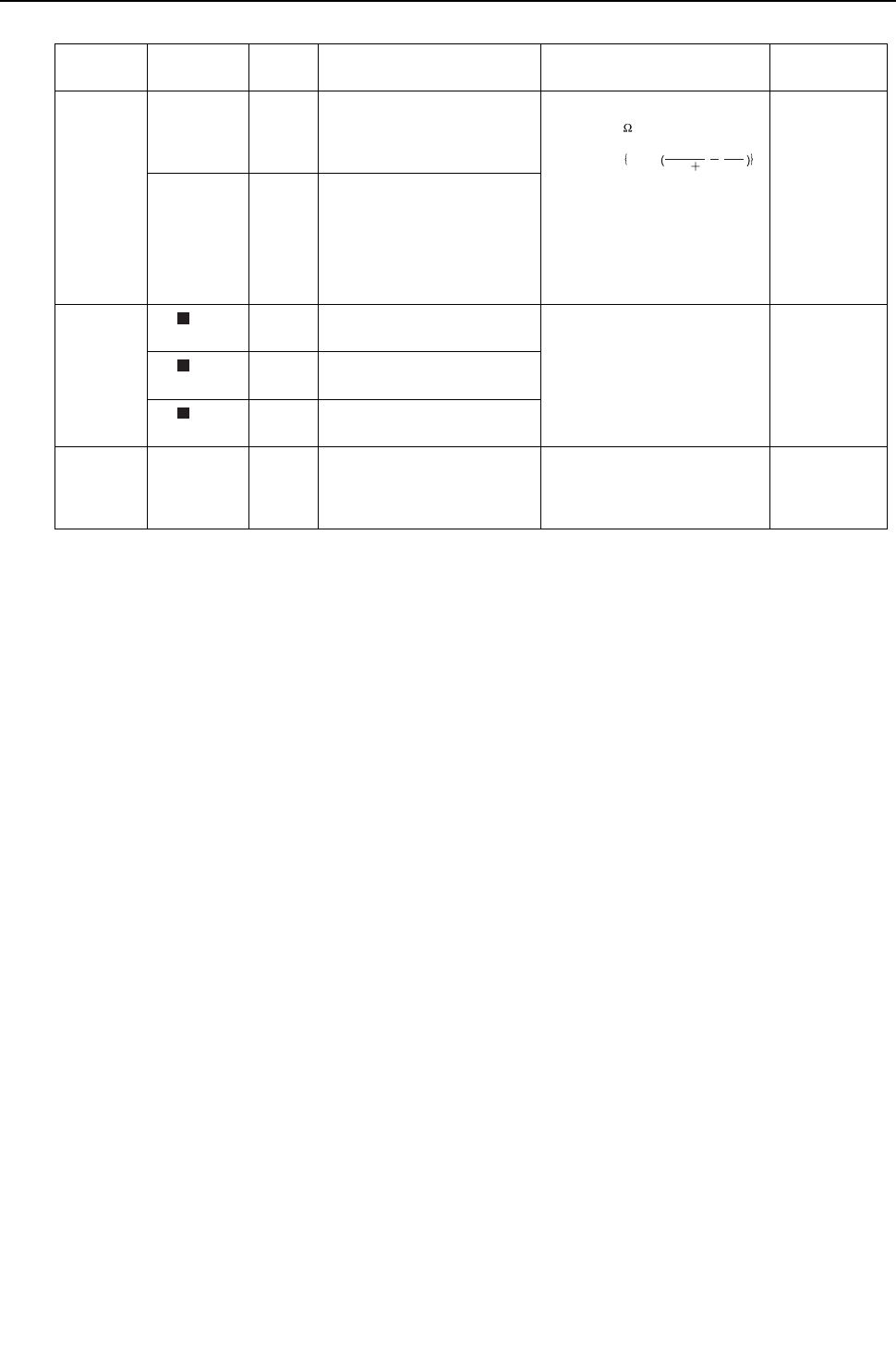
[ VI Refrigerant Circuit ]
- 133 -
HWE09080 GB
(4) HB type
Part name Symbols
(functions)
Part
code Usage Specifications Check method
Thermistor TH12
(Bypass
outlet tem-
perature)
LEV control (Superheat)
0°C[32°F] : 15kohm
10°C[50°F] :9.7kohm
20°C[68°F] :6.4kohm
25°C[77°F] :5.3kohm
30°C[86°F] :4.3kohm
40°C[104°F] :3.1kohm
TH15
(Bypass in-
let tempera-
ture)
LEV control (Superheat)
Solenoid
valve
SV A Provides refrigerant to indoor
unit in cooling operation
AC208-230V
Open while being powered/
closed while not being pow-
ered
Continuity
check with a
tester
SV B Provides refrigerant to indoor
unit in heating operation
SV C Provides refrigerant to indoor
unit in cooling operation
LEV LEV3 Pressure differential control DC12V
Opening of a valve driven by a
stepping motor
0-2000 pulses
Same as
indoor LEV
R = 15k
0
R = 3460
R = 15
0/80
t
3460
273 t
1
273
1
exp

- 134 -
[ VI Refrigerant Circuit ]
GBHWE09080

- 135 -
HWE09080 GB
VII
Control
[1] Functions and Factory Settings of the Dipswitches ....................................................... 137
[2] Controlling the Heat source Unit.................................................................................... 143
[3] Controlling BC Controller ............................................................................................... 160
[4] Operation Flow Chart.....................................................................................................161

- 136 -
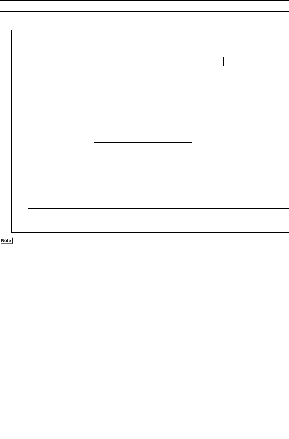
[ VII Control ]
- 137 -
HWE09080 GB
VII Control
[1] Functions and Factory Settings of the Dipswitches
1. Heat source unit
(1) Control board
1) Unless otherwise specified, leave the switch to OFF where indicated by "-," which may be set to OFF for a reason.
2) A: Only the switch on either the OC or OS needs to be set for the setting to be effective on both units.
B: The switches on both the OC and OS need to be set to the same setting for the setting to be effective.
C: The setting is effective for the unit on which the setting is made.
3) Refer to "VII [2] Controlling the Heat source Unit" for details.(page 143)
Switch Function Function according to switch setting Switch setting timing
Units that re-
quire switch
setting
Note.2
OFF ON OFF ON OC OS
SWU 1-2 Unit address setting Set to 00 or 51-100 with the dial switch Before power on C C
SW1 1-10 For self-diagnosis/
operation monitoring
Refer to the LED monitor display on the
heat source unit board. Anytime after power on CC
SW2
1Centralized control
switch
Without connection
to the centralized
controller
With connection to
the centralized con-
troller
Before power on
BB
2Deletion of connec-
tion information Normal control Deletion Before power on A-
3Deletion of error his-
tory SW
(OC) Storage of IC/
OC error history
(OC) Deletion of IC/
OC error history Anytime after power on
(When switched from OFF
to ON)
CC
(OS) Storage of OS
error history
(OS) Deletion of
OS error history
4 Pump down mode Normal control Pump down mode
After being energized and
while the compressor is
stopped
A-
5- - - - --
6- - - - --
7Power on signal out-
put switch During Thermo-ON During Thermo-
OFF Anytime after power on A-
8- - - - --
9- - - - --
10 - - - - - -
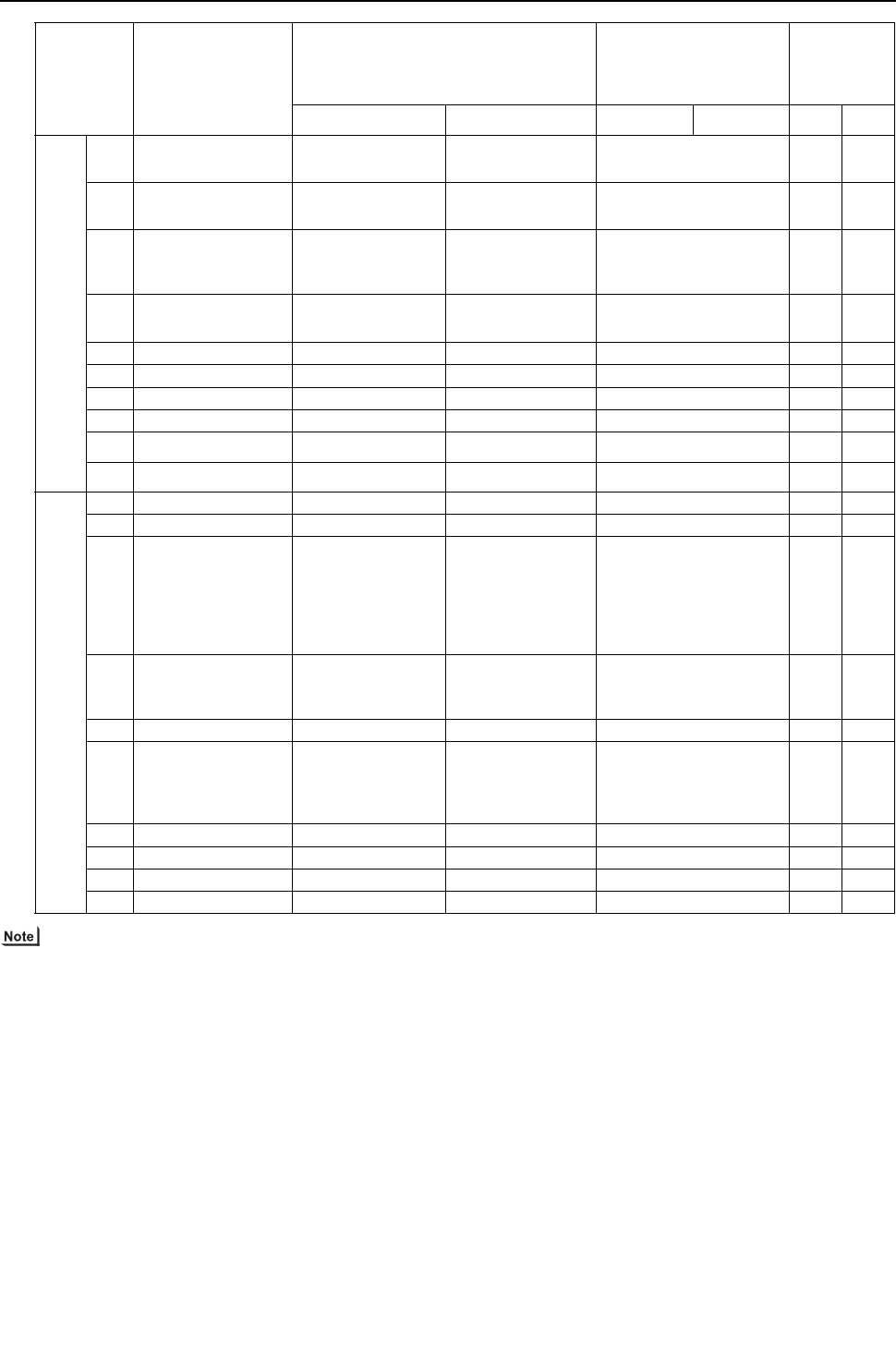
[ VII Control ]
- 138 -
HWE09080 GB
1) Unless otherwise specified, leave the switch to OFF where indicated by "-," which may be set to OFF for a reason.
2) A: Only the switch on either the OC or OS needs to be set for the setting to be effective on both units.
B: The switches on both the OC and OS need to be set to the same setting for the setting to be effective.
C: The setting is effective for the unit on which the setting is made.
3) The noise level is reduced by controlling the compressor frequency.
A setting of CN3D is required.(page 24)
4) If the inlet water temperature (TH7) drops below 5ºC [41ºF] while the compressor is stopped, or the outlet water temperature
(TH8) drops below 3ºC [37ºF], Cooling-only operation will be performed to prevent freeze-ups.
This operation will terminate when one of the following conditions is met: 1) Both the TH7 and TH8 readings (water tempera-
ture) exceed 10ºC [50ºF], 2) Two hours have passed since the beginning of the Cooling-only operation, or 3) Signal to resume
normal operation is received.
Switch Function Function according to switch setting Switch setting timing
Units that re-
quire switch
setting
Note.2
OFF ON OFF ON OC OS
SW3
1Test run mode: en-
abled/disabled SW3-2 disabled SW3-2 enabled Anytime after power on A-
2Test run mode: ON/
OFF Stops all ICs Sends a test-run
signal to all IC
After power on and when
SW3-1 is on.
A-
3CN51-3,5 signal out-
put switch
Heat source unit er-
ror output
Water heat ex-
changer coupling
prevention output
Anytime after power on
CC
4Water heat exchang-
er freeze prevention Ineffective Effective
Note 4 Anytime after power on A-
5- - - - --
6- - - - --
7- - - - --
8- - - - --
9- - - - --
10 - - - - - -
SW4
1- - - - --
2- - - - --
3Refrigerant amount
adjustment
Normal operation
mode
Refrigerant amount
adjust mode
Anytime after being ener-
gized (except during ini-
tial startup mode.
Automatically cancelled
90 minutes after com-
pressor startup)
A-
4
Low-noise mode/
step demand switch-
ing
Low-noise mode
(Note 3) Step demand mode Before being energized
CC
5- - - - --
6
Cumulative com-
pressor operation
time data deletion
Cumulative com-
pressor operation
time data is re-
tained.
Cumulative com-
pressor operation
time data is delet-
ed.
Anytime after power on
(when the unit is turned
on)
CC
7- - - - --
8- - - - --
9- - - - --
10 - - - - - -
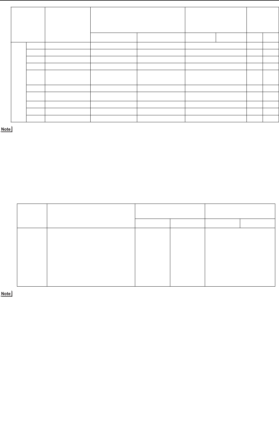
[ VII Control ]
- 139 -
HWE09080 GB
1) Unless otherwise specified, leave the switch to OFF where indicated by "-," which may be set to OFF for a reason.
2) A: Only the switch on either the OC or OS needs to be set for the setting to be effective on both units.
B: The switches on both the OC and OS need to be set to the same setting for the setting to be effective.
C: The setting is effective for the unit on which the setting is made.
3) When set to the capacity priority mode and if the following conditions are met, the quiet mode will terminate, and the unit will
go back into the normal operation mode.
Cooling-only/Cooling-main: High pressure is high.
Heating-only/Heating-main: Low pressure is low.
(2) INV board
Functions are switched with the following connector.
CN6 short-circuit connector is mated with the mating connector.
Leave the short-circuit connector on the mating connector during normal operation to enable error detection and protect the
equipment from damage.
Switch Function Function according to switch setting Switch setting timing
Units that re-
quire switch
setting
Note.2
OFF ON OFF ON OC OS
SW5
1- - - - --
2- - - - --
3- - - - --
4- - - - --
5Low-noise mode
selection
Capacity priority
mode(Note 3) Low-noise mode Before being energized A-
6- - - - --
7- - - - --
8- - - - --
9- - - - --
10 Backup heating Ineffective Effective Any time after power on A -
Connector Function
Function according to connec-
tor Setting timing
Enabled Disabled Enabled Disabled
CN6 short-
circuit con-
nector
Enabling/disabling the following error
detection functions;
ACCT sensor failure
(5301 Detail No. 115)
ACCT sensor circuit failure
(5301 Detail No.117)
IPM open/ACCT erroneous wiring
(5301 Detail No. 119)
Detection of ACCT erroneous wiring
(5301 Detail No.120)
Error detec-
tion enabled
Error detec-
tion disable
(No load op-
eration is pos-
sible.)
Anytime after power on
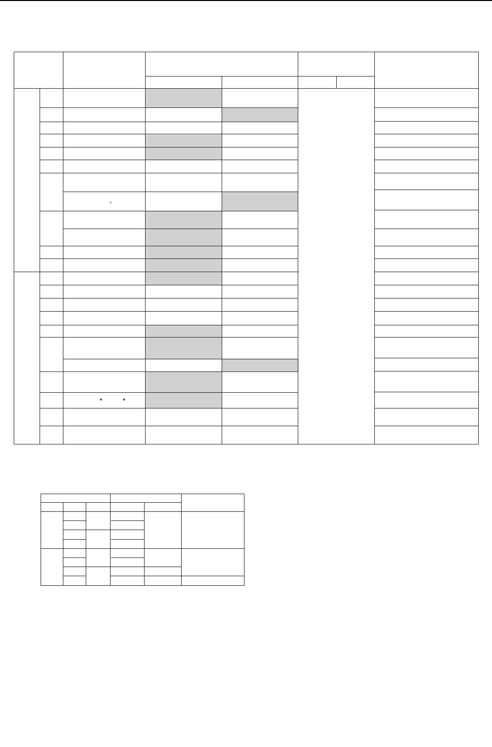
[ VII Control ]
- 140 -
HWE09080 GB
2. Function of the switch (Indoor unit)
(1) Dipswitches
1) SW1,3
SW3-1
OFF
OFF OFF
ON
ON
ON
OFF
ON
OFF
ON
OFF
ON
OFF
ON
Very Low
Low
Preset speed
Preset speed
Preset speed
Stop
Stop
Stop
-
-
-
Stop
Switch setting
SW1-7 SW1-8 Heating Cooling
Cooling-only/heat pump
Heat pump
Cooling-only
Heat pump
Fan speed during Thermo-OFF
Note 2. If both SW1-7 and SW1-8 are set to ON, the fan remains stopped during heating Thermo-OFF.
To prevent incorrect temperature detection due to a build-up of warm air around the indoor unit, use the built-in temperature sensor on the remote controller (SW1-1)
instead of the one on the indoor unit inlet thermistor.
Note 3. By setting SW3-1, SW1-7, and SW1-8 to a certain configuration, the fan can be set to remain stopped during cooling Thermo-OFF. See the table below for details.
Switch Function Function according to switch setting
OFF ON
Switch setting timing
OFF ON Notes
SW1
SW3
1
2
3
4
5
6
7
8
9
10
9
10
1
2
3
4
5
6
7
8
Room temperature
detection position
Clogged filter detection
Filter check reminder time setting
Outside air intake
Remote display option
Humidifier control
Self-recovery after power failure
Fan speed setting for
Heating Thermo-OFF
Power source start-stop
Unit model selection
Louver
Vane
Vane swing function
-
Vane angle limit setting
for cooling operation
Initial vane position
Heating 4 C[7.2 F] up
Automatic LEV value
conversion function
Indoor unit inlet
100h
Disabled
Fan output
2500h
Enabled
Thermo-ON signal
Built-in sensor on
the remote controller
Available
During heating operation
According to the
SW1-7 setting
Heat pump
Always on while in the heating mode
Fan speed setting for
Heating Thermo-OFF
Very Low Low
Preset speed
Cooling only
Enabled
Enabled
Disabled
Disabled Enabled
Enabled
Not available Available
Not available Available
Not available
Not available
Available
Not available
Available
Not available Available
--
---
Downblow B,C Horizontal
While the unit is stopped
(Remote controller OFF)
Always set to OFF on PKFY-P-NBMU-E model units
Set to ON (built-in sensor on the remote controller)
on All Fresh (PEFY-P-NMHU-E-F) model units
Applicable to All Fresh model units
(PEFY-P-NMHU-E-F) only
Applicable to All Fresh model units
(PEFY-P-NMHU-E-F) only
Always set to OFF on PKFY-P-NBMU-E model units
PLFY-P-NLMU-E model only
Set to OFF on floor-standing
(PFFY) type units
Note 1. Settings in the shaded areas are factory settings.(Refer to the table below for the factory setting of the switches whose factory settings are not indicated by the shaded cells.)
Always set to Downblow B or C on
PKFY-P-NBMU-E model units
Disabled
SHm setting 2
The setting depends on the
model and type.
The setting depends on the
model and type.
5
SCm setting 10 15
Disabled
Forced heating operation
at OA temp of 5 C or below
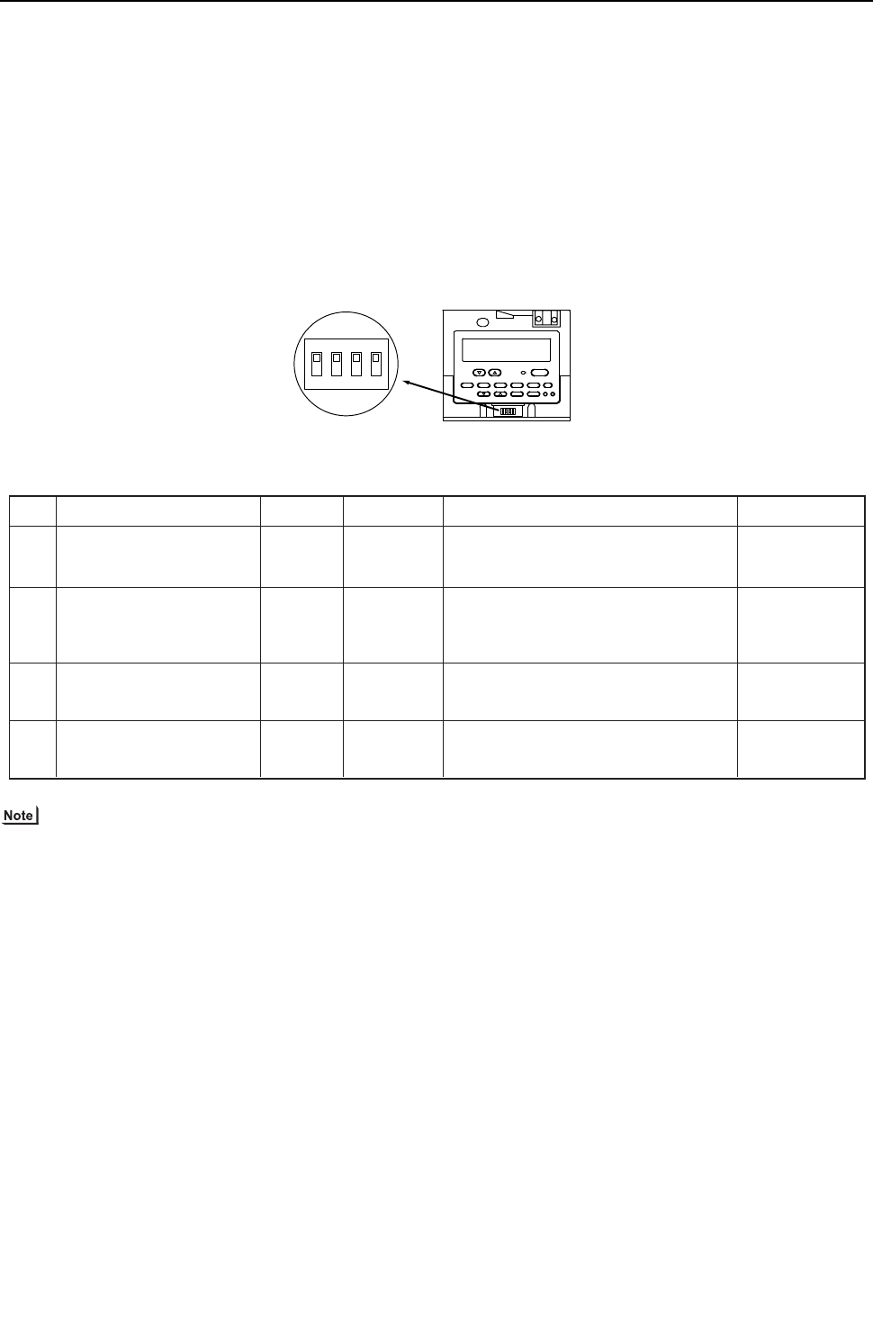
[ VII Control ]
- 141 -
HWE09080 GB
(2) Address switch
Actual indoor unit address setting varies in different systems. Refer to the installation manual for the heat source unit for details
on how to make the address setting.
Each address is set with a combination of the settings for the 10's digit and 1's digit.
(Example)
When setting the address to "3", set the 1's digit to 3, and the 10's digit to 0.
When setting the address to "25", set the 1's digit to 5, and the 10's digit to 2.
3. Function of the switch <Remote controller>
(1) MA remote controller (PAR-20MAA)
The SW is located at the bottom of the remote controller under the cover. Operate the switches to perform the remote con-
troller main/sub setting or other function settings. Normally, do not change the settings of switches other than the SW1 (main/
sub switching switch). (All the switches are set to "ON" at factory setting.)
The MA remote controller (PAR-21MAA) does not have the switches listed above. Refer to the installation manual for the func-
tion setting.
Remote controllerSwitching switch
1
ON
234
Switch
2
1
Function
Remote controller
main/sub setting
At power on of the
remote controller
Normal
startup
Timer mode
startup
3Cooling/heating display
set by automatic setting Displayed Not displayed
4Suction temperature display
(discharge temperature display) Displayed Not displayed
Operation by switch settings
Switch setting timing
ON OFF
Main Sub
Before power on
Before power on
Before power on
Before power on
When two remote controllers are connected
to one group, set either of the remote
controllers to "Sub".
When the program timer (only few stock
products are available) is connected, set to
"Timer mode startup" to resume the operation
with timer mode after power is restored.
When the automatic mode is set and the
"Cooling"/"Heating" display is not necessary,
set to "Not displayed".
When the suction temperature (discharge
temperature) display is not necessary,
set to "Not displayed".
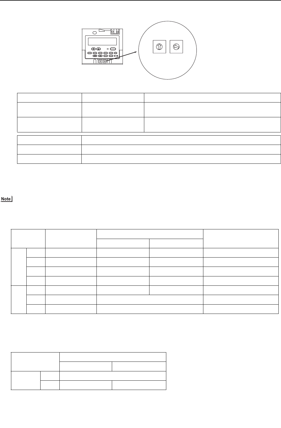
[ VII Control ]
- 142 -
HWE09080 GB
(2) ME remote controller (PAR-F27MEA)
Set the address of the remote controller with the rotary switch.
To set addresses, use a precision slotted screw driver [2.0 mm [0.08 in] (w)], and do not apply than 19.6N.
The use of any other tool or applying too much load may damage the switch.
4. Switch functions <BC controller> (Control board)
Model setting
0
1
2
3
4
5
6
7
8
9
0
1
2
3
4
5
6
7
8
9
0
1
2
3
4
5
6
7
8
9
0
1
2
3
4
5
6
7
8
9
10's digit 1's digit
(left) (right)
Remote controller unit
Rotary switch
Example: In case of address 108
Address setting range Setting method
Main remote controller 101-150 Add 100 to the smallest address of all the indoor units in the
same group.
Sub remote controller 151-200 Add 150 to the smallest address of all the indoor units in the
same group.
Setting of rotary switch Address No.
01-99*1 101-199 with the 100's digit automatically being set to 1*2
00 200
*1. At factory shipment, the rotary switch is set to 01.
*2. The address range that can be set with the ME remote controller is between 101 and 200. When the dials are set to
a number between 01 and 99, the 100's digit is automatically set to [1]. When the dials are set to 00, the 100's digit is
automatically set to [2].
Switch Function Function according to switch setting Switch setting timing
OFF ON
SW4
1 Model setting R410A - Always leave this switch to OFF.
2 - 5 - - - -
6 No. of ports *1
*1. When a junction pipe kit was used to merge two ports to connect the indoor units with a total capacity of between P31
and P54, turn DIP SW4-6 to ON. When connecting a main and a sub BC controller, change the SW setting on only the
main BC controller. (It is not necessary to change the SW setting on the sub BC controller. )
1 2 Before being energized
7, 8 - - - -
SW5
1 - 6 - - - -
7 Model setting Refer to the table below. Before being energized
8 Model setting Refer to the table below. Before being energized
Switch SW5-8
OFF ON
SW5-7 OFF G type
ON GAtype GB (HB) type
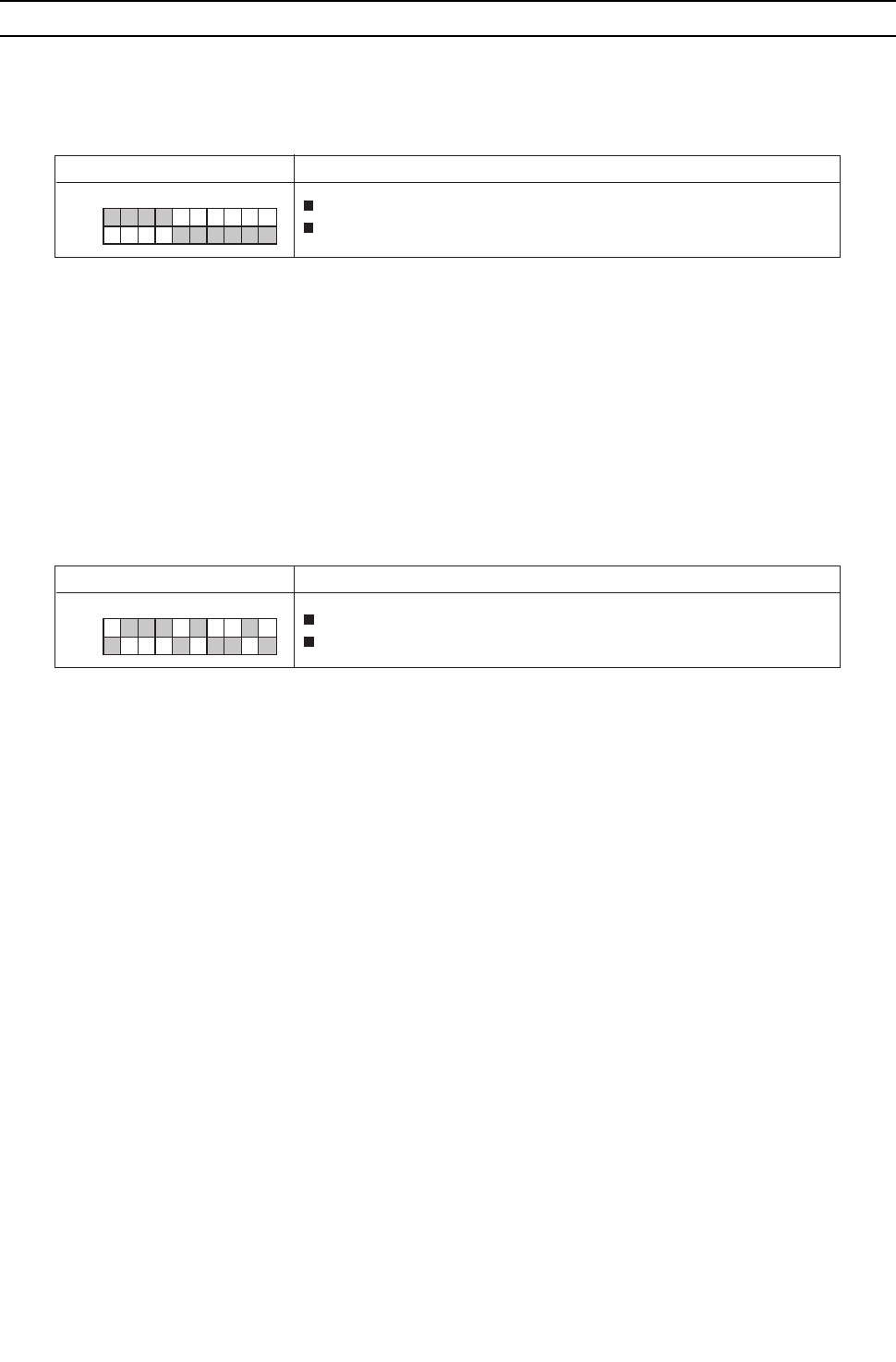
[ VII Control ]
- 143 -
HWE09080 GB
[2] Controlling the Heat source Unit
-1- Outline of Control Method
The heat source units are designated as OC and OS in the order of capacity from large to small (if two or more units have the
same capacity, in the order of address from small to large).
The setting of heat source unit can be verified by using the self-diagnosis switch (SW1).
The OC determines the operation mode and the control mode, and it also communicates with the indoor units.
The OS exercises autonomous distributed control (over defrost, error detection, and actuator control etc.) according to the
operation/control mode signals that are sent from the OC.
-2- Startup sequence rotation
At the initial startup, heat source units start up in the order of "OC and OS."
Startup sequence rotation is performed while all the indoor units are stopped. (Even after two hours of operation, startup se-
quence rotation is not performed while the compressor is in operation.)
In a system with multiple heat source units (OC and OS), when the integrated operation time of the unit in operation (either
OC or OS) reaches one hour during a cooling operation at low outside temperature, that unit will stop and the other unit will
go into operation.
Refer to [-13-Control at Initial Start-up] for the initial startup.
Performing startup sequence rotation does not change the basic operation of OC and OS. Only startup sequence is changed.
Startup sequence of the heat source units can be checked with the self-diagnosis switch (SW1) on the OC.
-3- Initial Control
When the power is turned on, the initial processing of the microcomputer is given top priority.
During the initial processing, control processing of the operation signal is suspended. (The control processing is resumed after
the initial processing is completed. Initial processing involves data processing in the microcomputer and initial setting of each
of the LEV opening. This process will take up to 5 minutes.)
During the initial processing, the LED monitor on the heat source unit's control board displays S/W version -> refrigerant type
-> heat pump -> cooling only and capacity -> and communication address in turn every second.
-4- Control at Start-up
The upper limit of frequency during the first 3 minutes of the operation is 50 Hz.
When the power is turned on, normal operation will start after the initial start-up mode (to be described later) has been com-
pleted (with a restriction on the frequency).
Display
SW1
ON
1 2 3 5 4 6 7 8 9 10
The unit is designated as the OC: “oc” appears on the display.
The unit is designated as OS: “oS” appears on the display
Display SW1
OC→OS: “oc” and the “OC” address appear alternately on the display.
OS→OC: “oS” and the “OS” address appear alternately on the display.
ON
1 2 3 5 4 6 7 8 9 10
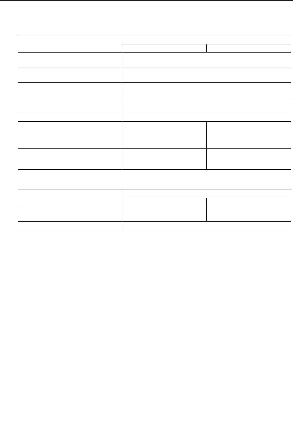
[ VII Control ]
- 144 -
HWE09080 GB
-5- Bypass Control
Bypass solenoid valves (SV1a), which bypass the high- and low- pressure sides, perform the following functions.
(1) Bypass solenoid valve (SV1a) (ON = Open)
(2) Bypass solenoid valve (SV9) (ON = Close)
Operation SV1a
ON OFF
When the compressor on each heat source
unit starts up
ON for 4 minutes.
After the restoration of thermo or 3 minutes
after restart
ON for 4 minutes.
During cooling or heating operation with the
compressor stopped
Always ON.
Exception: OFF when 63HS1-63LS is 0.2MPa[29psi] or less
After the operation has stopped ON for 3 minutes.
Exception: OFF when 63HS1-63LS is 0.2MPa[29psi] or less
During defrost operation ON
While the compressor is operating at the
minimum frequency and when the low pres-
sure (63LS) drops (3 or more minutes after
compressor startup)
When low pressure (63LS) drops
below 0.23MPa[33psi].
When low pressure (63LS) ex-
ceeds 0.38MPa[55psi].
When high pressure (63HS1) rises When 63HS1 exceeds
3.62MPa[525psi]
When 63HS1 is or below
3.43MPa[497psi] and 30 seconds
have passed
Operation SV9
OFF ON
When high pressure (63HS1) rises during
the heating operation
When 63HS1 exceeds 3.50MPa
[507psi]
When the pressure is
2.70MPa[391psi]or below
Others Always ON

[ VII Control ]
- 145 -
HWE09080 GB
-6- Compressor Frequency Control
Depending on the capacity required, the frequency of the compressor is controlled to keep constant evaporation temperature
(0°C [32°F] = 0.71 MPa [103 psi]) during cooling operation, and condensing temperature (49°C [120°F] = 2.88 MPa [418 psi])
during heating operation.
The table below summarizes the operating frequency ranges of the inverter compressor during normal operation.
The OS in the multiple-heat source-unit system operates at the actual compressor frequency value that is calculated by the
OS based on the preliminary compressor frequency value that the OC determines.
The maximum frequency during heating operation is affected by the water temperature to a certain extent.
(1) Pressure limit
The upper limit of high pressure (63HS1) is preset, and when it exceeds the upper limit, the frequency is decreased every 15
seconds.
The actuation pressure is when the high-pressure reading on 63HS1 is 3.58MPa[519psi].
(2) Discharge temperature limit
Discharge temperature (TH4) of the compressor in operation is monitored, and when it exceeds the upper limit, the frequency
is decreased every minute.
Operating temperature is 115°C [239°F].
(3) Periodic frequency control
Frequency control other than the ones performed at start-up, upon status change, and for protection is called periodic frequen-
cy control (convergent control) and is performed in the following manner.
Periodic control cycle
Periodic control is performed after the following time has passed
30 seconds after compressor start-up
30 seconds after frequency control based on discharge temperature or pressure limit
The amount of frequency change
The amount of frequency change is controlled to approximate the target value based on the evaporation temperature (Te) and
condensing temperature (Tc).
Model Frequency/cooling (Hz) Frequency/heating (Hz)
Max Min Max Min
P72 model 66 35 66 15
P96 model 90 35 80 15
P120 model 114 35 104 15

[ VII Control ]
- 146 -
HWE09080 GB
-7- Refrigerant Recovery Control <PQHY>
Recovery of refrigerant is performed during heating operation to prevent the refrigerant from accumulating inside the unit while
it is stopped (unit in fan mode), or inside the indoor unit that is in cooling mode or in heating mode with thermo off. It is also
performed during cooling operation to prevent an excessive amount of refrigerant from accumulating in the heat source heat
exchanger.
(1) During heating operation
Starting refrigerant recovery mode
The refrigerant recovery mode in heating starts when all of the following three conditions are met:
15 minutes have passed since the completion of previous refrigerant recovery.
TH4 > 115°C [239°F]
Frequencies below 50 Hz
Refrigerant recovery
1) Refrigerant is recovered with the LEV on the applicable indoor unit (unit under stopping mode, fan mode, cooling, heating with
thermo off) being opened for 30 seconds.
2) Periodic capacity control of the heat source units and periodic LEV control of the indoor units will be suspended during refrig-
erant recovery operation; they will be performed after the recovery has been completed.
(2) During cooling operation
Starting refrigerant recovery mode
The refrigerant recovery mode starts when all the following conditions are met:
30 minutes have passed since the completion of previous refrigerant recovery.
When the unit keeps running for 3 minutes in a row or more with high discharge temperature
TH4 > 105°C [221°F] or 63HS1 > 3.43 MPa [497 psi] (35 kg/cm2G) and SC0 > 10°C [18°F]
Refrigerant recovery
The opening of LEV1 is increased and periodic control begins again.
-8- Refrigerant Recovery Control <PQRY>
Refrigerant recovery is performed for each BC port during heating operation to prevent the refrigerant from accumulating in-
side the units that are stopped (in the fan mode), in the cooling mode, or in the heating Thermo-OFF mode.
It is also performed during cooling operation to prevent an excessive amount of refrigerant from accumulating in the heat
source heat exchanger.
Starting criteria for the refrigerant recovery cycle (during Cooling-only, Cooling-main, Heating-only, or Heating-main
mode)
The refrigerant recovery mode starts when all of the following conditions are met:
1) When 5 minutes have passed in the Heating-only or Heating-main mode or 30 seconds have passed in the Cooling-only or
Cooling-main mode since the completion of the previous refrigerant recovery cycle AND the when following conditions are
met.
TH4 > 105°C [221°F]
2) When the port is not in the 4-minute restart delay mode
Starting criteria for the refrigerant recovery cycle (during Cooling-only, Cooling-main, Heating-only, or Heating-main
mode)
1) When the port is in the cooling Thermo-OFF, fan, or stop mode
SV C at the port turns on for 30 seconds. ( indicates port No.)
2) The opening of LEV1 and LEV3 is increased.
-9- Capacity Control of Heat Exchanger<PQHY>
(1) Control method
Depending on the capacity required, the rotation speed of the heat source unit fan is controlled by the inverter to keep a con-
stant condensing temperature of (water temperature +10°C [50°F]) during cooling operation and a constant evaporation tem-
perature of (0°C [32°F] =0.71 <Pa [103psi]) during heating operation.
The OS in the multiple-heat source-unit system operates at the actual heat source unit fan control value that is calculated by
the OS based on the preliminary heat source unit fan control value that the OC determines.
Opening of LEV during refrigerant recovery
Opening of indoor unit LEV: 400 pulses
Initial opening of LEV
Start Finish
30 seconds
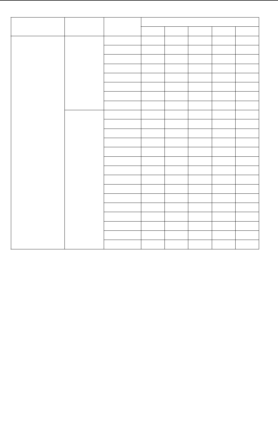
[ VII Control ]
- 147 -
HWE09080 GB
(2) Heat source unit heat exchanger capacity control patterns
Model Operation mode Operation
pattern
Solenoid valve
SV4a SV4b SV4d SV7a SV7b
P72-P120 models Cooling 1 ON OFF OFF ON ON
2ONOFFOFFOFFON
3 ONOFFOFFONOFF
4 ON OFF OFF OFF OFF
5ONONOFFONON
6ONONOFFOFFON
7 ON ON OFF ON OFF
8 ON ON OFF OFF OFF
Heating 1 ON OFF ON ON ON
2 ON OFF ON OFF ON
3 ON OFF ON ON OFF
4 ON OFF ON OFF OFF
5 ONONONONON
6ONONONOFFON
7ONONONONOFF
8ONONONOFFOFF
9ONOFFOFFONON
10 ON OFF OFF OFF ON
11 ON OFF OFF ON OFF
12 ON ON OFF ON ON
13 ON ON OFF OFF ON
14 ON ON OFF ON OFF
15 ON ON OFF OFF OFF
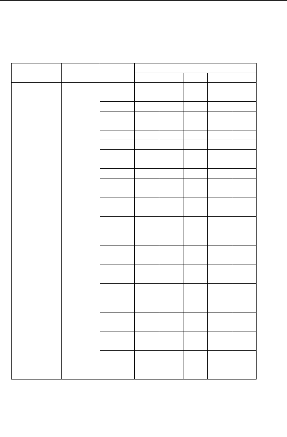
[ VII Control ]
- 148 -
HWE09080 GB
-10- Capacity Control of Heat Exchanger<PQRY>
(1) Control method
Depending on the capacity required, the rotation speed of the heat source unit fan is controlled by the inverter to keep a con-
stant condensing temperature of (water temperature +10°C [50°F]) during cooling operation and a constant evaporation tem-
perature of (0°C [32°F] =0.71 <Pa [103psi]) during heating operation.
The OS in the multiple-heat source-unit system operates at the actual heat source unit fan control value that is calculated by
the OS based on the preliminary heat source unit fan control value that the OC determines.
(2) Heat source unit heat exchanger capacity control patterns
Model Operation
mode
Operation
pattern
Solenoid valve
SV4a SV4b SV4d SV7a SV7b
P72 - P120 models Cooling-main 1 ON OFF ON ON ON
2 ON OFF ON OFF ON
3 ON OFF ON ON OFF
4 ON OFF ON OFF OFF
5 ONONONONON
6ONONONOFFON
7 ONONONONOFF
8ONONONOFFOFF
Cooling-only
Cooling-main
9ONOFFOFFONON
10 ON OFF OFF OFF ON
11 ON OFF OFF ON OFF
12 ON OFF OFF OFF OFF
13 ON ON OFF ON ON
14 ON ON OFF OFF ON
15 ON ON OFF ON OFF
16 ON ON OFF OFF OFF
Heating-only
Heating-main
1 ON OFF ON ON ON
2 ON OFF ON OFF ON
3 ON OFF ON ON OFF
4 ON OFF ON OFF OFF
5 ONONONONON
6ONONONOFFON
7 ONONONONOFF
8ONONONOFFOFF
9ONOFFOFFONON
10 ON OFF OFF OFF ON
11 ON OFF OFF ON OFF
12 ON ON OFF ON ON
13 ON ON OFF OFF ON
14 ON ON OFF ON OFF
15 ON ON OFF OFF OFF
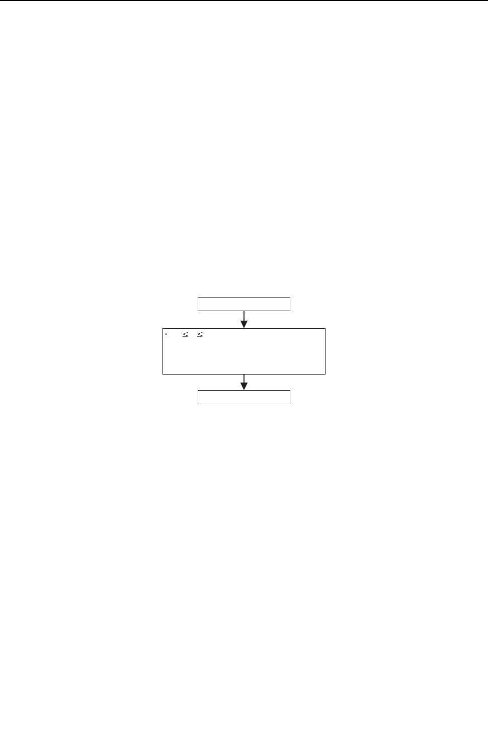
[ VII Control ]
- 149 -
HWE09080 GB
-11- Subcool Coil Control (Linear Expansion Valve <LEV1>) <PQHY only>
The OC, OS1, and OS2 controls the subcool coil individually.
The LEV is controlled every 30 seconds to maintain constant the subcool at the heat source unit heat exchanger outlet that
is calculated from the values of high pressure (63HS1) and liquid piping temperature (TH3), or the superheat that is calculated
from the values of low pressure (63LS) and the bypass outlet temperature (TH2) of the subcool coil.
LEV opening is controlled based on the values of the inlet (TH6) and the outlet (TH3) temperatures of the subcool coil, high
pressure (63HS1), and discharge temperature (TH4). In a single-heat source-unit system, the LEV is closed (0) in the heating
mode, while the compressor is stopped, and during cooling Thermo-OFF. In a multiple-heat source-unit system, the LEV clos-
es (0) during heating operation, while the compressor is stopped, or during cooling Thermo-OFF. The LEV opens to a speci-
fied position when 15 minutes have passed after Thermo-OFF. (65 pulses)
LEV1 outputs 0 pulse during the defrost cycle, and 300 pulses if either of the following formulas are satisfied: 63LS<2kgf/cm2
or TH4100ºC [212ºF].
-12- Refrigerant flow control (Linear expansion valve <LEV2a, LEV2b>)<PQHY only>
Refrigerant flow is controlled by each unit in the combined models during heating. Refrigerant flow control is performed by the
OC, OS1, and OS2 individually. The valve opens to a specified angle during cooling (Opening: 1400 pulses)
Valve opening is controlled based on the values of high pressure (63HS1), discharge temperature (TH4), low pressure(
63LS), and piping temperature (TH5).
The valve moves to the predetermined position while the unit is stopped.
-13- Control at Initial Start-up
When started up for the first time before 12 hours have elapsed after power on, the unit goes into the initial startup mode.
At the completion of the initial operation mode on the OC, OS1, and OS2, they will go into the normal control mode.
1. Flowchart of initial operation
(1) P72, P96, P120 models
50 F 60Hz
or F < 50Hz
Initial startup mode starts.
Completed in the integrated operation time of 35 minutes.
Initial startup mode complete
Completed in the integrated operation time of 90 minutes.
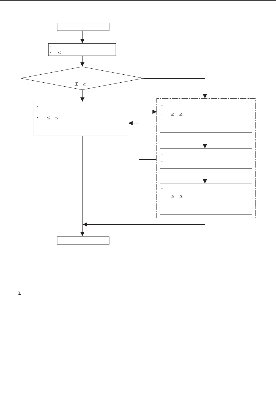
[ VII Control ]
- 150 -
HWE09080 GB
(2) P144, P168, P192, P216, P240 models
*1 Qj:Total capacity (model name) code
Yes
No
50 F 60Hz (both OC and OS)
or F < 50Hz (both OC and OS)
Completed in the integrated operation time of 35 minutes.
Completed in the integrated operation time of 90 minutes.
The compressor on the OC remains in operation, and the
compressor on the OS starts up.
50 F 60Hz (OC)
or F < 50Hz (OC)
Completed in the integrated operation time of 35 minutes.
Completed in the integrated operation time of 90 minutes.
The compressor on the OC starts up.
Both the OC and OS stop.
The startup sequence of the OC and OS is rotated.
50 F 60Hz (OS)
or F < 50Hz (OS)
Completed in the integrated operation time of 35 minutes.
Completed in the integrated operation time of 90 minutes.
The compressor on the OS starts up.
*2
*3
*2
The air conditioning load is too small
for both the OC and the OS to
simultaneously stay in operation.
*3
The air conditioning load is
high enough for both OC and OS to
simultaneously stay in operation.
Initial startup mode complete
The compressor on the OC starts up.
The total operating load of the indoor unit
after 5 minutes of operation is P96 or above.
(
*1
Qj 50)
Initial startup mode starts.
F 60Hz
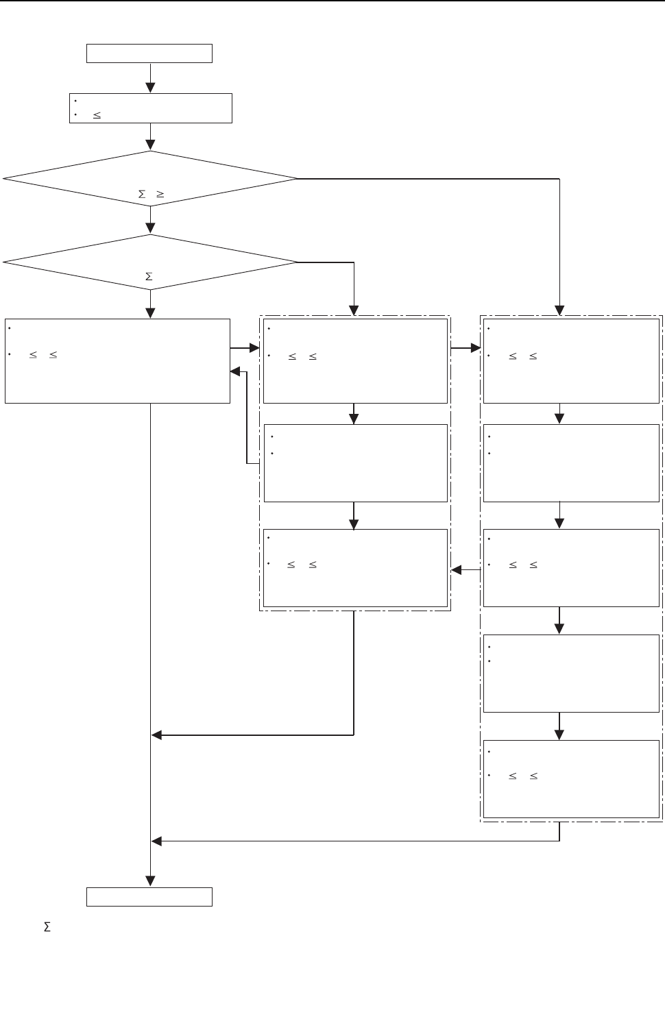
[ VII Control ]
- 151 -
HWE09080 GB
(3) P264, P288, P312, P336, P360 models <PQHY only>
*1 Qj:Total capacity (model name) code
Initial startup mode starts.
The compressor on the OC starts up.
F 60Hz
The total operating load of the indoor unit
after 5 minutes of operation is P96 or above.
(
*1
Qj 50)
The total operating load of the indoor unit after
5 minutes of operation is between P96 and P400.
(50 <
*1
Qj< 200)
50 F 60Hz (OC, OS1, and OS2)
or F < 50Hz (OC, OS1, and OS2)
Completed in the integrated operation time of 35 minutes.
Completed in the integrated operation time of 90 minutes.
The compressor on the OS remains in operation, and the
compressors on the OS1 and OS2 start up.
50 F 60Hz (both OC and OS1)
or F < 50Hz (both OC and OS1)
Completed in the integrated operation time of 35 minutes.
Completed in the integrated operation time of 90 minutes.
The compressor on the OC remains in operation,
and the compressor on the OS1 starts up.
50 F 60Hz (OC)
or F < 50Hz (OC)
Completed in the integrated operation time of 35 minutes.
Completed in the integrated operation time of 90 minutes.
The compressor on the OC starts up.
The OC, OS1, and OS2 stop.
The startup sequence of the OC,
OS1, and OS2 is rotated.
(The startup sequence of the OC,
OS1 and OS2 is changed.)
The OC, OS1, and OS2 stop.
The startup sequence of the OC, OS1,
and OS2 is rotated.
(The startup sequence of the OC,
OS1 and OS2 is changed.)
The OC, OS1, and OS2 stop.
The startup sequence of the OC,
OS1, and OS2 is rotated.
(The startup sequence of the OC,
OS1 and OS2 is changed.)
50 F 60Hz (OS1)
or F < 50Hz (OS1)
Completed in the integrated operation time of 35 minutes.
Completed in the integrated operation time of 90 minutes.
The compressor on the OS1 starts up.
50 F 60Hz (OS2)
or F < 50Hz (OS2)
Completed in the integrated operation time of 35 minutes.
Completed in the integrated operation time of 90 minutes.
The compressor on the OS2 starts up.
*2 *3
*4
*5
Yes
No
No
Yes
Initial startup mode complete
50 F 60Hz (both OS1 and OS2)
Completed in the integrated operation time of 35 minutes.
Completed in the integrated operation time of 90 minutes.
The compressor on the OS1 remains in operation,
and the compressor on the OS2 starts up.
or F < 50Hz (both OS1 and OS2)
*2
The air conditioning load is
too small for the OC, OS1,
and OS2 to simultaneously
stay in operation.
*3
The air conditioning load is
too small for both OC and
OS1, or OS1 and OS2 to
simultaneously stay in
operation.
*4
The air conditioning load is
high enough for OC, OS1
and OS2 to simultaneously
stay in operation.
*5
The air conditioning load is
high enough for both OC
and OS1, or OS1 and OS2
to simultaneously stay in
operation.
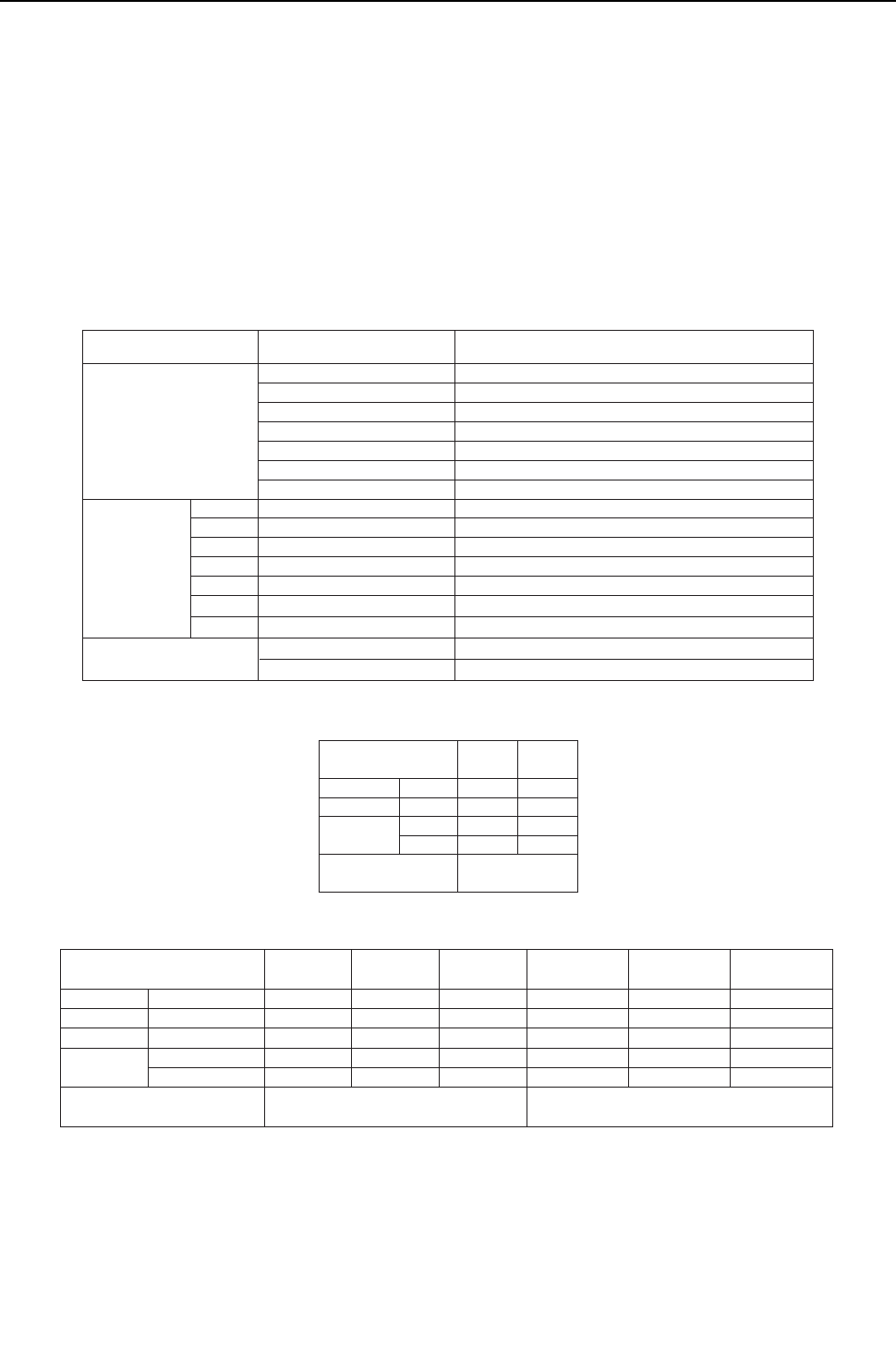
[ VII Control ]
- 152 -
HWE09080 GB
-14- Emergency Operation Mode
1. Problems with the heat source unit
Emergency operation mode is a temporary operation mode in which the heat source unit that is not in trouble operates when
one of the heat source units in the P144 through P240 models is in trouble or when one or two of the heat source units in the
P264 through P360 models are in trouble.
This mode can be started by performing an error reset via the remote controller.
(1) Starting the emergency operation
1) When an error occurs, the error source and the error code will be displayed on the display on the remote controller.
2) The error is reset using the remote controller.
3) If an error code appears that permits an emergency operation in step 1) above, (See the table below.), the retry operation
starts.
4) If the same error is detected during the retry operation (step 3 above), an emergency operation can be started by resetting
the error via the remote controller.
Error codes that permit an emergency operation (Applicable to both OC and OS)
Emergency operation pattern (2 heat source units)
Emergency operation pattern (3 heat source units)
Trouble source Error codes that permit an
emergency operation Error code description
Serial communication error
Bus voltage drop
Heatsink overheat protection
Overload protection
Overcurrent relay trip
Heatsink temperature sensor failure (THHS)
Current sensor/circuit failure
Subcool heat exchanger bypass outlet temperature sensor failure
Pipe temperature sensor failure
Discharge temperature sensor failure
Accumulator inlet temperature sensor failure
Subcool heat exchanger liquid outlet sensor failure
Outside air temperature sensor failure
Open phase
Power supply sync signal abnormality
0403
4220, 4225
4230
4240
4250, 4255
5110
5301
5102
5103
5104
5105
5106
5107
4102
4115
Compressor
Inverter
Thermistor
Power
TH2
TH3
TH4
TH5
TH6
TH7
Water outlet temperature sensor fault5108
TH8
OC
OC failure
pattern
Trouble
Normal
Permitted Permitted
Permitted Permitted
60%
Cooling
Heating
Normal
Trouble
OS failure
pattern
OS
Emergency
operation
Maximum total capacity
of indoor units (Note 1)
OC
OC failure
pattern
Trouble Trouble Trouble
Normal
Normal NormalNormal
Normal Normal
60% 40%
Cooling
Heating
Normal Normal Normal
Trouble
Trouble Trouble Trouble
Trouble Trouble
OS1 failure
pattern
OS2 failure
pattern
OC, OS1 failure
pattern
OC, OS2 failure
pattern
OS1, OS2 failure
pattern
OS1
OS2
Emergency
operation
Maximum total capacity
of indoor units (Note 1)
(Note 1) If an attempt is made to put into operation a group of indoor units whose total capacity exceeds the maximum allowable capacity,
some of the indoor units will go into the same condition as Thermo-OFF.
Permitted
Permitted
Permitted
Permitted
Permitted
Permitted
Permitted
Permitted
Permitted
Permitted
Permitted
Permitted
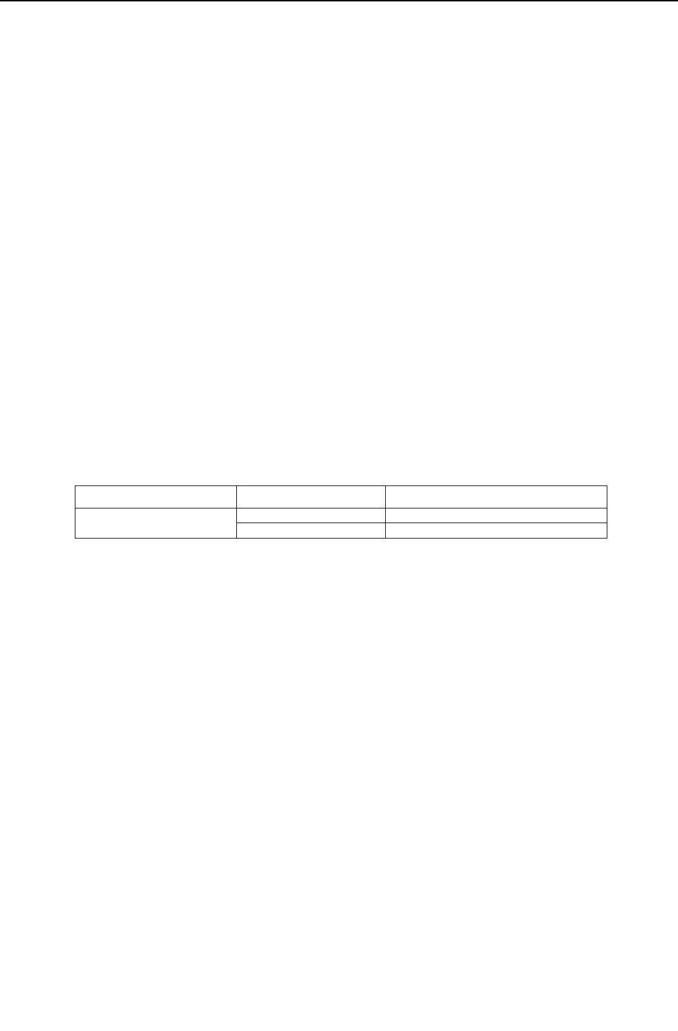
[ VII Control ]
- 153 -
HWE09080 GB
(2) Ending the emergency operation
1) End conditions
When one of the following conditions is met, emergency operation stops, and the unit makes an error stop.
When the integrated operation time of compressor in cooling mode has reached four hours.
When the integrated operation time of compressor in heating mode has reached two hours.
When an error is detected that does not permit the unit to perform an emergency operation.
2) Control at or after the completion of emergency operation
At or after the completion of emergency operation, the compressor stops, and the error code reappears on the remote con-
troller.
If another error reset is performed at the completion of an emergency mode, the unit repeats the procedures in section (1)
above.
To stop the emergency mode and perform a current-carrying operation after correcting the error, perform a power reset.
2. Communication circuit failure or when some of the heat source units are turned off
This is a temporary operation mode in which the heat source unit that is not in trouble operates when communication circuit
failure occurs or when some of the heat source units are turned off.
(1) Starting the emergency operation (When the OC is in trouble)
1) When an error occurs, the error source and the error code appear on the display on the remote controller.
2) Reset the error via the remote controller to start an emergency operation.
Precautions before servicing the unit
When the OC is in trouble, the OS temporarily takes over the OC's function and performs an emergency operation. When this
happens, the indoor unit connection information are changed.
In a system that has a billing function, a message indicating that the billing system information has an error may appear on
the TG-2000A. Even if this message appears, do not change (or set) the refrigerant system information on the TG-2000A.
After the completion of an emergency operation, the correct connection information will be restored.
(2) Starting the emergency operation (When the OS is in trouble)
1) A communication error occurs. -> An emergency operation starts in approximately six minutes.
Error codes that permit an emergency operation (Applicable to both OC and OS)
Trouble source
Circuit board failure or the power
to the heat source units is off
6607
6608
No acknowledgement error
No response error
Error codes that permit an
emergency operation Error code description

[ VII Control ]
- 154 -
HWE09080 GB
Emergency operation pattern (2 heat source units)
Emergency operation pattern (3 heat source units)
(3) Ending the emergency operation
When communication is restored, the emergency mode is cancelled, and the units go into the normal operation mode.
OC
Cooling
Heating
OC failure
pattern
Trouble
Normal
Permitted Permitted
Permitted Permitted
Normal
Trouble
OS failure
pattern
OS
Emergency
operation
Maximum total capacity
of indoor units (Note 1)
Capacity that matches
the total capacity of the
operable heat source
units
OC
OC failure
pattern
Trouble Trouble Trouble
Normal
Normal Normal Normal
Normal Normal
Cooling
Heating
Normal Normal Normal
Trouble
Trouble Trouble Trouble
Trouble Trouble
OS1 failure
pattern
OS2 failure
pattern
OC, OS1 failure
pattern
OS1
OS2
Emergency
operation
Maximum total capacity
of indoor units (Note 1) Capacity that matches the total capacity of the operable heat source units
(Note 1) If an attempt is made to put into operation a group of indoor units whose total capacity exceeds the maximum allowable capacity,
some of the indoor units will go into the same condition as Thermo-OFF.
Permitted
Permitted
Permitted
Permitted
Permitted
Permitted
Permitted
Permitted
Permitted
Permitted
Permitted
Permitted
OC, OS2 failure
pattern
OS1, OS2 failure
pattern
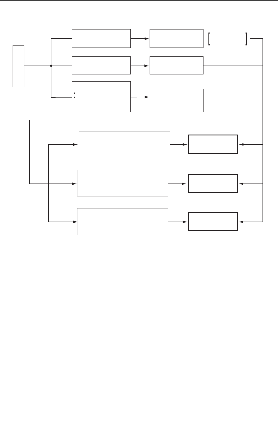
[ VII Control ]
- 155 -
HWE09080 GB
-15- Control Method <PQRY only>
The control system configuration for the PQRY models is shown in the chart below.
Control method
Data signal exchange
between system equipment
Calculation, processing
System control
Adjustment of refrigerant flow rate
Adjustment of rotation speed of
compressor or fan
Non-polar 2-wire
serial communication
method
16-bit CPU
microcomputer operation
processing
Autonomous distributed
control system
(F2-VPM control)
Rotation speed control of compressor
or fan depending on the refrigerant
pressure value and the changing speed
Self-contained capacity control depending
on the load
Refrigerant distribution control depending
on the operation mode
Heat source unit
Daisy-chained
non-polar 2-wire
transmission line
Indoor unit
BC controller
*
Autonomous distributed control system : A system that consists of three independent sub control systems,
instead of a single centralized control system, that work together
to maintain the overall control of the entire system.
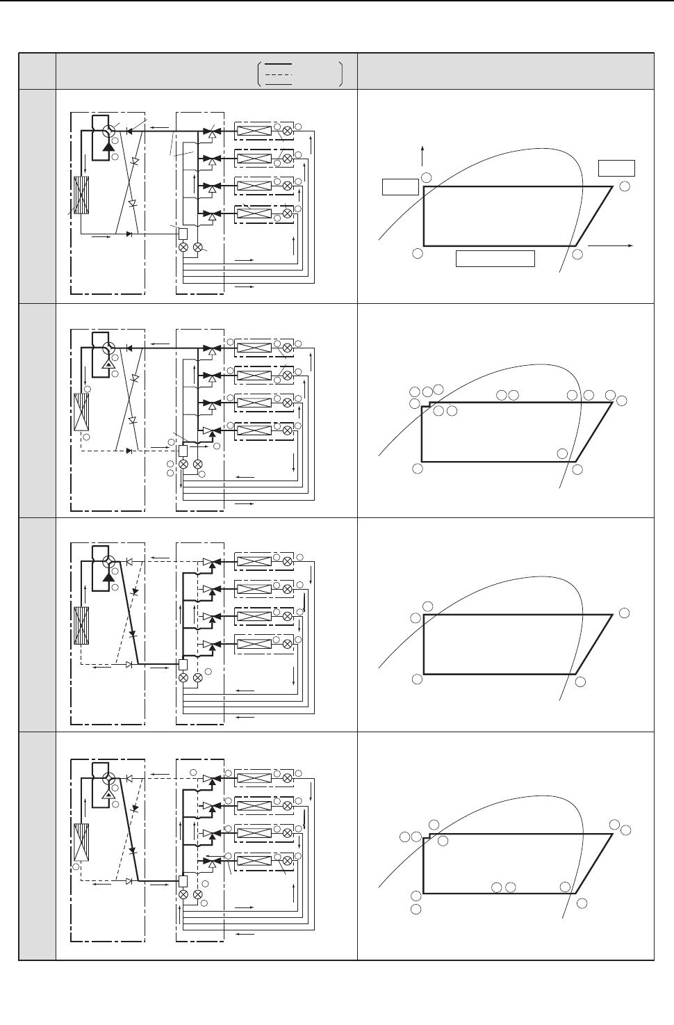
[ VII Control ]
- 156 -
HWE09080 GB
-16- Cooling/heating Circuit Control and General Function of System Equipment
High-pressure gasHigh-pressure gas
Heat exchanger
High-pressure
liquid
4-way valve
Check valve
Selector valve
Low-pressure two-phase
Low-pressure two-phase
Low-
pressure
two- phase
High-pressure liquid
Low-
pressure
two- phase
Low-
pressure
two- phase
Heat exchanger
High-pressure
liquid
High-pressure
liquid
High-pressure
liquid
High-pressure
liquid
High-pressure liquid
Cooling
Cooling
Cooling
Heating
Cooling
Heating
Heating
Heating
Low-
pressure
pipe
High-
pressure
pipe
High-
pressure
gas
High-
pressure
gas
High-
pressure
gas
High-pressure
two-phase
Low-pressure
gas
Low-pressure
gas
Low-pressure gasLow-pressure gas
Low-
pressure
gas
Gas-liquid
separator
Heat source unit BC controller
Indoor unit
LEV
LEV
ML
ML
M
L
M
L
A
O
M
L
M
L
M
L
M
L
A
O
B
C
D
I
J
J
E
F
F
N
N
N
K
ML
ML
M
L
GH
A
O
L
J G I
K H
D C F E B
N
A
MO
J
G
I
KH
D
C
F
E
BA
M
L
F
MA
O
M
L
A
O
M
A
I
E
K
BCD
BCD
BCD
F
G
H
Gas-liquid mixture
Pressure
Liquid
Gas
Enthalpy
(energy)
Schematic diagram of refrigerant circuit
Gas
Two-phase
Liquid
Schematic diagram of refrigerating cycle
Cooling
only
Operation
status
Cooling
main
Heating
only
Heating
main

[ VII Control ]
- 157 -
HWE09080 GB
-17- Operation Mode <PQHY>
(1) Indoor unit operation mode
The operation mode can be selected from the following 5 modes using the remote controller.
(2) Heat source unit operation mode
When the heat source unit is performing a cooling operation, the operation mode of the connected indoor units that are not in
the cooling mode (Stopped, Fan, Thermo-OFF) cannot be changed to heating from the remote controller. If this attempt is
mode, "Heating" will flash on the remote controller. The opposite is true when the heat source unit is performing a heating
operation. (The first selection has the priority.)
1 Cooling mode
2 Heating mode
3 Dry mode
4Fan mode
5 Stopped mode
1 Cooling mode All indoor units in operation are in cooling mode.
2 Heating mode All indoor units in operation are in heating mode.
3 Stopped mode All indoor units are in fan mode or stopping mode.
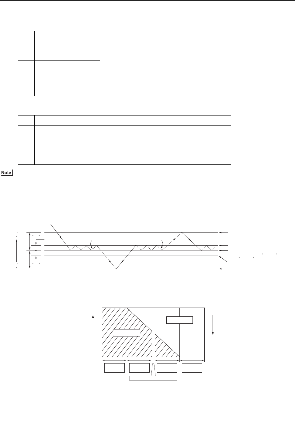
[ VII Control ]
- 158 -
HWE09080 GB
-18- Operation Mode <PQRY>
(1) Indoor unit operation mode
The operation mode can be selected from the following 6 modes using the remote controller.
(2) Heat source unit operation mode
When units in cooing and heating coexist, the operation mode (cooling main mode or heating main mode) will be determined
by the heat source unit, based on the refrigerant pressure and speed variation data.
(3) Operation pattern for automatic cooling/heating mode
When the automatic cooling/heating mode is selected from remote controller functions, the indoor temperature will be detect-
ed in pattern as shown in the figure below, and the operation mode (cooling or heating) will automatically be selected.
(4) Relationship between the operation mode and the load capacity (kW) (within a system)
1 Cooling mode
2 Heating mode
3 Dry mode
4 Automatic cooling/heating
mode
5Fan mode
6 Stopping mode
1 Cooling only mode All indoor units in operation are in cooling mode.
2 Heating only mode All indoor units in operation are in heating mode.
3 Cooling main mode Coexistence of units in cooling and heating modes.
4 Heating main mode Coexistence of units in cooling and heating modes.
5 Stopping mode All indoor units are in fan mode or stopping mode.
Cooling Fan
Heating
Switches to cooling mode
Cooling operation under
Thermo-ON conditions
Set temperature
(Variable between 19 C and 28 C
[ 67 F and 83 F])
Heating operation under Thermo-ON conditions
Switches to heating mode
Fan
Temperature
rise
1.5 C
[3 F]
1.5 C
[3 F]
1 C [2 F]
1 C [2 F]
Cooling load
capacity
Heating load
capacity
+
Cooling load
capacity
Heating load
capacity
Heating load
capacity
+
Cooling load
capacity
100(%)
Cooling only
mode
Cooling main
mode
Heating main
mode
Total heat recovery mode
Heating only
mode
100(%)
Heating
load (%)
Heating load
X100 = Cooling
load (%)
=
Cooling load
X 100
0
0

[ VII Control ]
- 159 -
HWE09080 GB
-19- DEMAND Control
Cooling/heating operation can be prohibited (Thermo-OFF) by an external input to the heat source units.
When DIP SW4-4 is set to ON, the 4-step DEMAND control is enabled.
Eight-step demand control is possible in the system with two heat source units.
Twelve-step demand control is possible in the system with three heat source units.
Refer to Chapter II [3] 2.(7) "Various types of control using input-output signal connector on the heat source unit (various con-
nection options)" for details.(page 22)
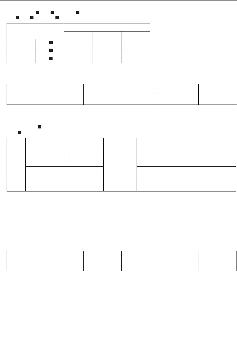
[ VII Control ]
- 160 -
HWE09080 GB
[3] Controlling BC Controller
1. Control of SV A, SV B, and SV C
SV A, SV B, and SV C turn on or off depending on the operation mode of the branch.
2. Control of SVM1 and 1b
SVM turns on or off depending on the operation mode.
3. Control of LEV
LEV opening (sj) is controlled as follows depending on the operation mode.
4. Control of SVM2, and 2b
Mode
Cooling Heating Stopped
Port
SV A ON OFF OFF
SV B OFF ON OFF
SV C ON OFF OFF
Operation mode Cooling only Cooling main Heating only Heating main Stopped
SVM1,1b ON Pressure differen-
tial control*1
*1. Pressure differential control: The detected differential pressure (PS1 and PS3) is controlle every minute so as to be within
a certain range.
OFF OFF OFF
Operation mode Cooling only Cooling main Heating only Heating main Stopped
G,GA
type
LEV1
2000 Liquid level
control*1differ-
ential control*2
*1. Liquid level control: The liquid level detected by the liquid inlet temperature (TH11 sensor) is controlled so as to be within
a certain range.
*2. Pressure differential control: The detected differential pressure (PS1 and PS3) is controlle every minute so as to be within
a certain range.
110 110*3
*3. Can be 110 or more due to pressure rise on the liquid side (PS1).
1200
LEV2
(only GA type)
LEV3 Superheat con-
trol*4
*4. Superheat control: The amound of superheat that is calculated on the bypass inlet and outlet temperature (G, GA,
:TH12,TH15, GB, HB: TH12, TH15) is controlled every minute so as to be within a certain range.
Pressure differ-
ential control*2 Pressure differ-
ential control*2 60
GB,HB
type LEV3 Superheat con-
trol*4 Superheat con-
trol*4 60 60 60
Operation mode Cooling only Cooling main Heating only Heating main Stopped
SVM2,2b OFF OFF Pressure differen-
tial control*1
*1. Pressure differential control: The detected differential pressure (PS1 and PS3) is controlled every minute so as to be within
a certain range.
Pressure differen-
tial control*1 OFF
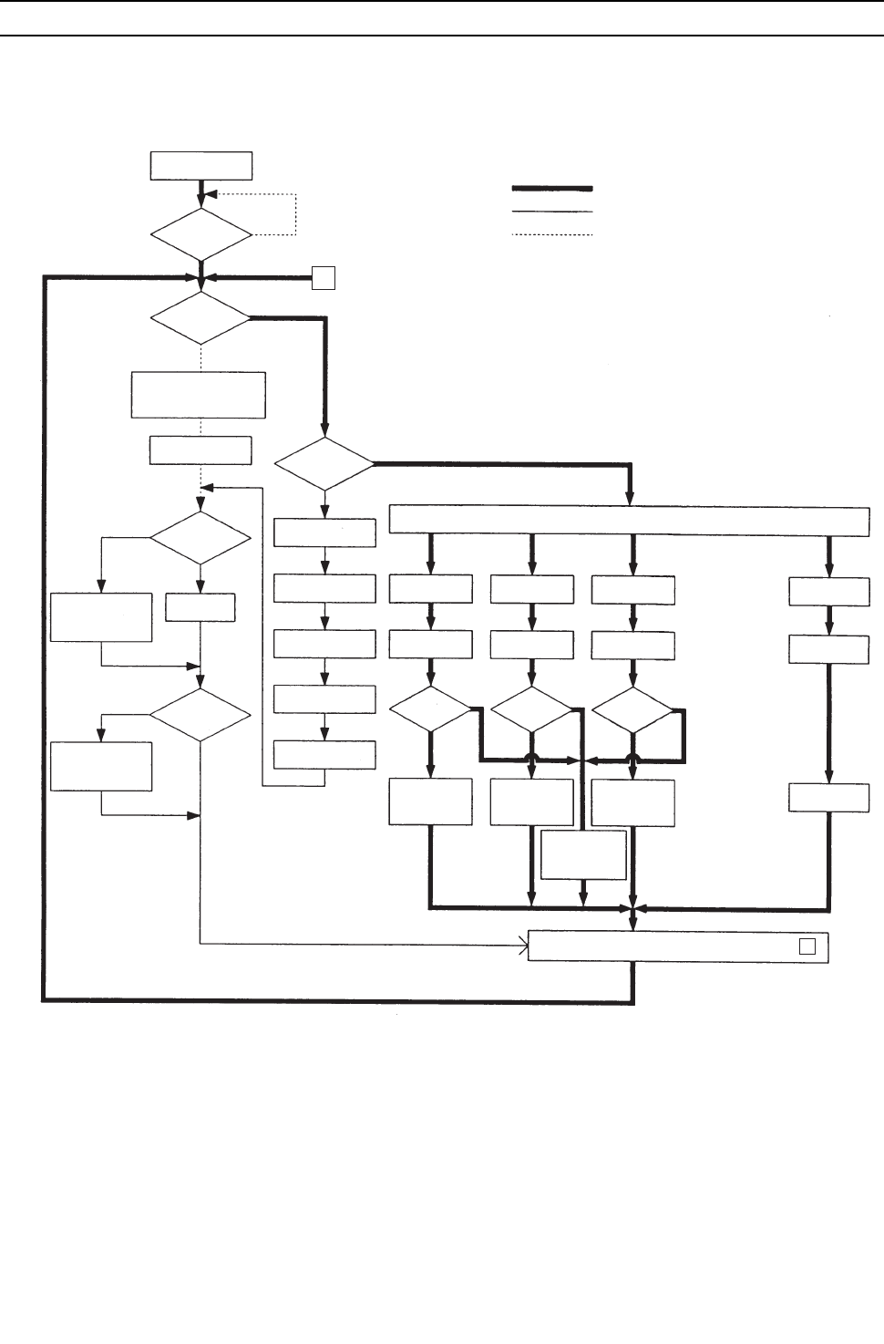
[ VII Control ]
- 161 -
HWE09080 GB
[4] Operation Flow Chart
1. Mode determination flowchart <PQHY>
(1) Indoor unit (cooling, heating, dry, fan mode)
*Note 1. Indoor unit LEV fully closed : Opening 41.
*Note 2. The system may go into the error mode on either the indoor unit or the heat source unit side. If some of the indoor units are
experiencing a problem (except water leakage), only those indoor units that are experiencing the problems will stop.
If the heat source unit is experiencing a problem, all connected indoor units will stop.
*Note 3. The operation will be prohibited when the set cooling/heating mode is different from that of the heat source unit.
Start
Remote controller
display lit off
Error mode
Error stop
Error display
Self-holding of
protection function
Error command
to heat source unit
Indoor unit LEV
fully closed.
Refer to 2-(1)
Cooling operation.
Refer to 2-(2)
Heating operation.
Refer to 2-(3)
for dry operation.
ProhibitionProhibitionProhibition
Dry display
Heating displayCooling display
Dry mode
Heating mode
Fan mode
Fan display
Fan operations
Operation mode
Cooling mode
Operation command to heat source unit (to 2 )
Prohibition
"Blinking display on
the remote controller"
FAN stop
Breaker
turned on
Operation SW
turned on
Auxiliary heater
ON
Drain pump
ON
3-minute
drain pump ON
NO
NO
NO
NO
NO NO NO NO
*Note 1
*Note 2
*Note 1
*Note 3 *Note 3 *Note 3
1. Protection function
self-holding cancelled.
2. Indoor unit LEV fully closed.
1. Auxiliary heater OFF
2. Low fan speed for
1 minute
YES
YES
YES
YES
YES YES YES
YES
Normal operation
Error
Unit in the stopped state
From heat source unit
1
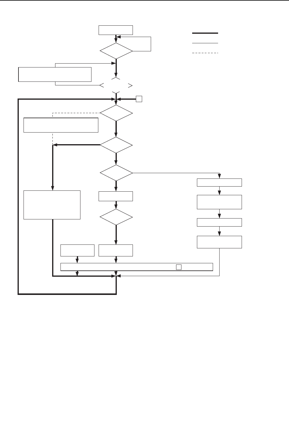
[ VII Control ]
- 162 -
HWE09080 GB
(2) Heat source unit (cooling and heating modes)
*Note 1. For about 3 minutes after power on, search for the indoor unit address, for the remote controller address,
and for the group information will start. During this, "HO" / "PLEASE WAIT" blinks on the display of the remote
controller. When the indoor unit to be controlled by the remote controller is missing, "HO" / "PLEASE WAIT" keeps
blinking on the display of the remote controller even after 3 or more minutes after power on.
*Note 2. The system may go into the error mode on either the indoor unit or the heat source unit side. The heat source unit
stops only when all of the connected indoor units are experiencing problems. The operation of even a single indoor
unit will keep the heat source unit running. The error will be indicated on the LED display.
*Note 3. The heat source unit operates according to the operation mode commanded by the indoor unit. However, when the
heat source unit is running a cooling operation, come of the operating indoor units will stop, or the operation of these
indoor units will be prohibited even when the indoor unit mode is switched from fan mode to heating mode.
This also applies when the heat source unit is running a heating operation.
Start
Breaker
turned on
Operation
command
Error stop
Error display on the
heat source unit LED
Error command to
indoor unit
Operation
mode
Operation
mode
Error mode
72C ON
*Note 1
*Note 3
*Note 2
YES
YES
YES
YES
NO
NO
NO
NO
"HO" / "PLEASE WAIT" blinks on
the remote controller
Operation command to indoor unit To 1 .
Cooling / Heating
1. Protection function self-holding cancelled.
2. LEV1 fully closed.
Normal operation
1. 72C OFF
2. Inverter output 0Hz
3. All solenoid valves OFF
Refer to Cooling/Dry
Operation 2-(1) and 2-(3)
Refer to
heating
Operation 2-(2).
2 From indoor unit
Error
Unit in the stopped state
Self-holding of
protection function
Indoor units
registered to the
remote controller
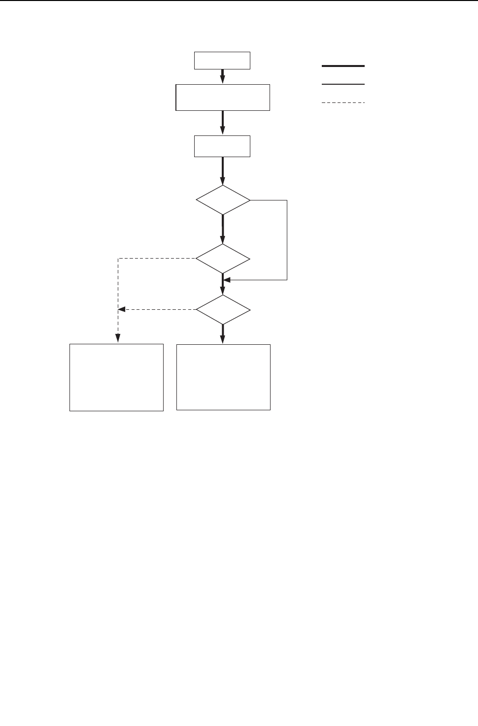
[ VII Control ]
- 163 -
HWE09080 GB
2. Operations in each mode
(1) Cooling operation
*Note 1. The indoor fan operates at the set notch under cooling mode regardless of the ON/OFF state of the thermostat.
Cooling operation
Test run mode
ON
Thermostat ON
3-minute restart
prevention
*Note 1
YES
YES
YES
NO
NO
NO
4-way valve OFF
1. I
nverter frequency control
2.
Indoor unit LEV, LEV1 control
LEV2a, LEV2b fully opened
3. Solenoid valve control
4. 72C control
Normal operation
During test run mode
Unit in the stopped state
Indoor unit fan
operation
1. Inverter output 0Hz
2. Indoor unit LEV, LEV1
LEV2a, LEV2b rated opening
3. All solenoid valves OFF
4. 72C OFF
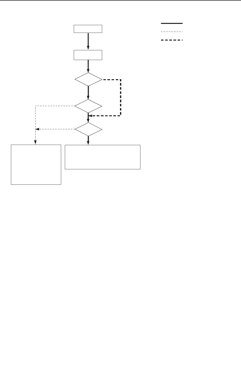
[ VII Control ]
- 164 -
HWE09080 GB
(2) Heating operation
Heating operation
Test run mode
ON
Thermostat ON
3-minute restart
prevention
YES
YES
YES
NO
NO
NO
NO
1. Indoor-heat source unit fan control
2. Inverter frequency control
3. Indoor unit LEV, LEV1,LEV2a, LEV2b control
4. Solenoid valve control
5. 72C control
Normal operation
4-way valve ON
During test run mode
1.
Indoor unit fan operation at
Very Low speed
2. Inverter output 0Hz
3.
Indoor unit LEV, LEV1 Fully closed
LEV2a, LEV2b rated opening
4. All solenoid valves OFF
5. Heat source unit fan stop
6. 72C OFF
Unit in the stopped state
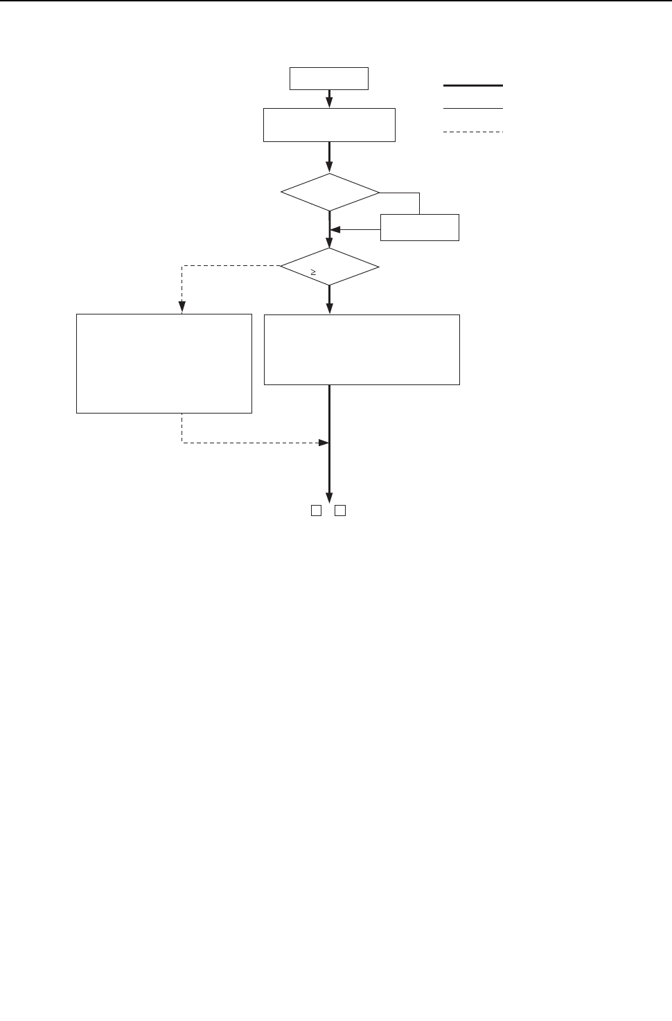
[ VII Control ]
- 165 -
HWE09080 GB
(3) Dry operation
Dry operation
*Note 1
*Note 2
YES
YES
NO
NO
4-way valve OFF
1. Heat source unit (compressor)
intermittent operation
2. Indoor unit fan intermittent operations
(Synchronized with the compressor:
low speed, OFF operations)
Normal operation
Thermostat ON
Thermostat ON
1. Indoor unit fan stop
2. Inverter output 0Hz
3. Indoor unit LEV, LEV1 fully closed.
LEV2a, LEV2b rated opening.
4. Solenoid valve OFF
5.
72C OFF
1 or 2
*Note 1.When the indoor unit inlet temperature exceeds 18°C [64°F], the heat source unit (compressor) and the
indoor unit fan start the intermittent operation simultaneously. When the indoor unit inlet temperature
becomes 18°C [64°F],or less, the fan always runs (at low speed). The heat source unit, the indoor unit,
and the solenoid valve operate in the same way as they do in the cooling operation when the compressor
is turned on.
*Note 2.Thermostat is always kept on during test run mode, and indoor and heat source unit intermittent operation
(ON) time is a little longer than that of normal operation.
Test run mode
ON
Suction temperature
18°C[64°F]
Unit in the stopped state
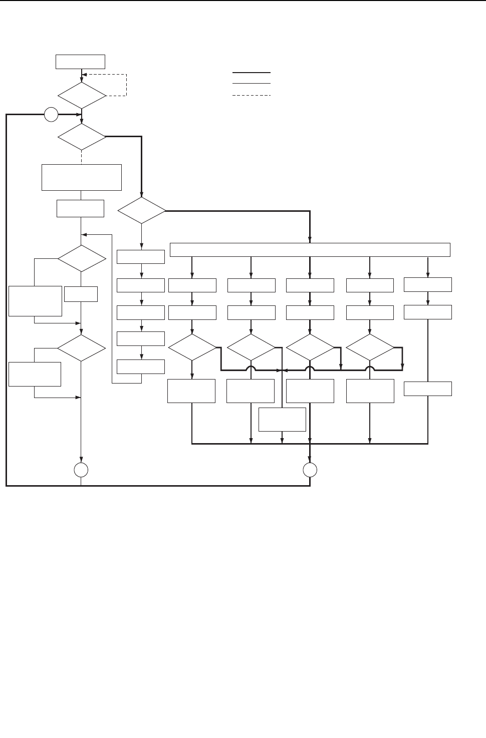
[ VII Control ]
- 166 -
HWE09080 GB
1. Mode determination flowchart <PQRY>
(1) Indoor unit (cooling, heating, dry, fan mode)
Start
Remote controller
display lit off
Error mode
Error stop
Error display
Self-holding of
protection function
Error command
to heat source unit
Indoor unit
LEV fully closed.
Refer to 2-(1) for
cooling operation.
Refer to 2-(2) for
heating operation.
Refer to 2-(3) for
dry operation.
ProhibitionProhibitionProhibition
Dry display
Heating displayCooling display
Dry modeHeating mode Fan mode
Fan display
Fan operations
Operation mode
Cooling mode
Prohibition
"Blinking display on
the remote controller"
FAN stop
Breaker
turned on
Operation SW
turned on
Auxiliary heater
ON
Drain pump
ON
3-minute drain
pump ON
NO
NO
NO
NO
NO NO NO NO NO
*Note 1
*Note 1
*Note 2
*Note 3 *Note 3 *Note 3
1. Protection function
self-holding cancelled.
2. Indoor unit LEV fully closed.
1. Auxiliary heater OFF
2. Low fan speed for
1 minute
YES
YES
YES
YES
YES YES YES
YES
Normal operation
Error
Stop
1
Prohibition
Auto COOL/HEAT
display
Automatic
cooling/heating mode
*Note 3
YES
Auto
cooling/heating mode
11
*Note 1. Indoor unit LEV fully closed : Opening 41.
*Note 2. The system may go into the error mode on either the indoor unit side or the BC controller or heat source unit side.
If some of the indoor units are experiencing a problem, only those indoor units that are experiencing the problem
will stop. If the BC controller or the heat source unit is experiencing a problem, all the connected units will stop.
*Note 3. If multiple indoor units are connected to a port and there is a discrepancy in the operation mode between the
indoor unit and the port, the operation will be prohibited. (Operation mode blinks on the remote controller, the
Fan stops, indoor unit LEV becomes fully closed.)
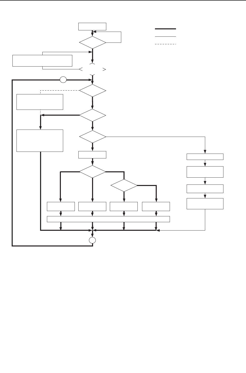
[ VII Control ]
- 167 -
HWE09080 GB
(2) Heat source unit (cooling only, heating only, cooling main and heating main modes)
Start
Breaker
turned on
Operation
command
Error stop
Error display on the
heat source unit LED
Self-holding of
protection function
Operation command
to the BC controller
Operation
mode
Error mode
72C ON
*Note 1
*Note 2
*Note 3
*Note 4
YES
YES
YES
YES
NO
NO
NO
fan
NO
"HO" / "PLEASE WAIT" blinks
on the remote controller
Operation command to the BC controller
Cooling only, Heating only
Mixture of units in cooling and heating
Mixture of units in cooling and heating
Protection function
self-holding cancelled.
Normal operation
1. 52C1 4-way valve OFF
2. Inverter output 0Hz
3. All solenoid valves OFF
Cooling Only Heating Only
2
2
Cooling Main
Operation
mode
Operation
mode
*Note 1. For about 3 minutes after power on, search for the indoor unit address, for the remote controller address,
and for the group information will start. During this, "HO"/ "PLEASE WAIT" blinks on the display of the
remote controller. When the indoor unit to be controlled by the remote controller is missing,
"HO"/ "PLEASE WAIT" keeps blinking on the display of the remote controller even after 3 or more minutes
after power on.
*Note 3. The units will follow the operation mode commands from the BC controller
*Note 4. When the operation mode commands from the BC controllers are mixed (both cooling and heating), the
actual operation mode is determined by the heat source unit.
*Note 2. The system may go into the error mode on either the indoor unit or the heat source unit side. The heat
source unit stops only when all of the connected indoor units are experiencing problems. The operation of
even a single indoor unit will keep the heat source unit running. The error will be indicated on the LED display.
Heating Main
Indoor units
registered to the
remote controller
Error
Unit in the stopped state
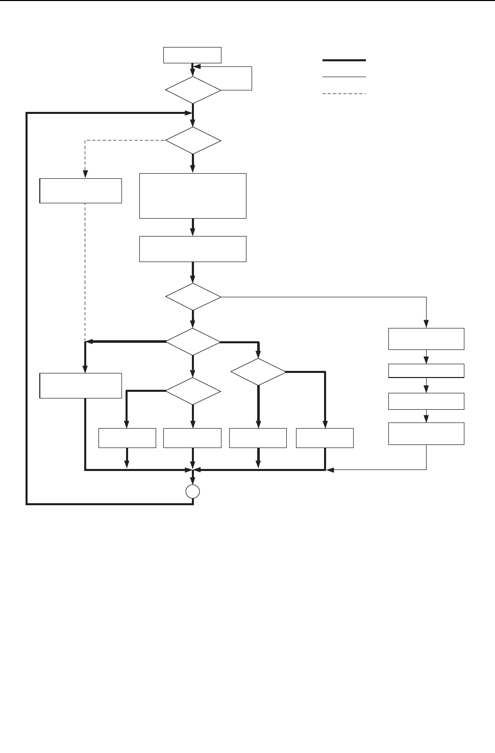
[ VII Control ]
- 168 -
HWE09080 GB
(3) BC controller (cooling only, heating only, cooling main and heating main modes)
Start
Breaker
turned on
Operation
command
Error command to
heat source unit
Error stop
Self-holding of
protection function
Error command to
indoor unit
Error mode
*Note 1
YES
YES
YES
NO
NO
Fan
NO
All units in the
same mode
Solenoid valves OFF
LEV Fully closed
1.
Determination of operation mode
(Cooling only, Heating only, Mixture
of units in cooling and heating)
2.
Transmitted to the heat source unit
3
Operation
mode
Note 1. The system may go into the error mode on either the indoor unit side or the BC controller or heat source
unit side. If some of the indoor units are experiencing a problem, only those indoor units that are
experiencing the problem will stop. If the BC controller or the heat source unit is experiencing a problem,
all the connected units will stop.
Operation
mode
Operation
mode
Cooling Only Heating Only Cooling Main Heating Main
Mixture of units in cooling and heating
Reception of operation mode
command from the heat source unit
Protection function
self-holding cancelled.
Normal operation
Error
Unit in the stopped state
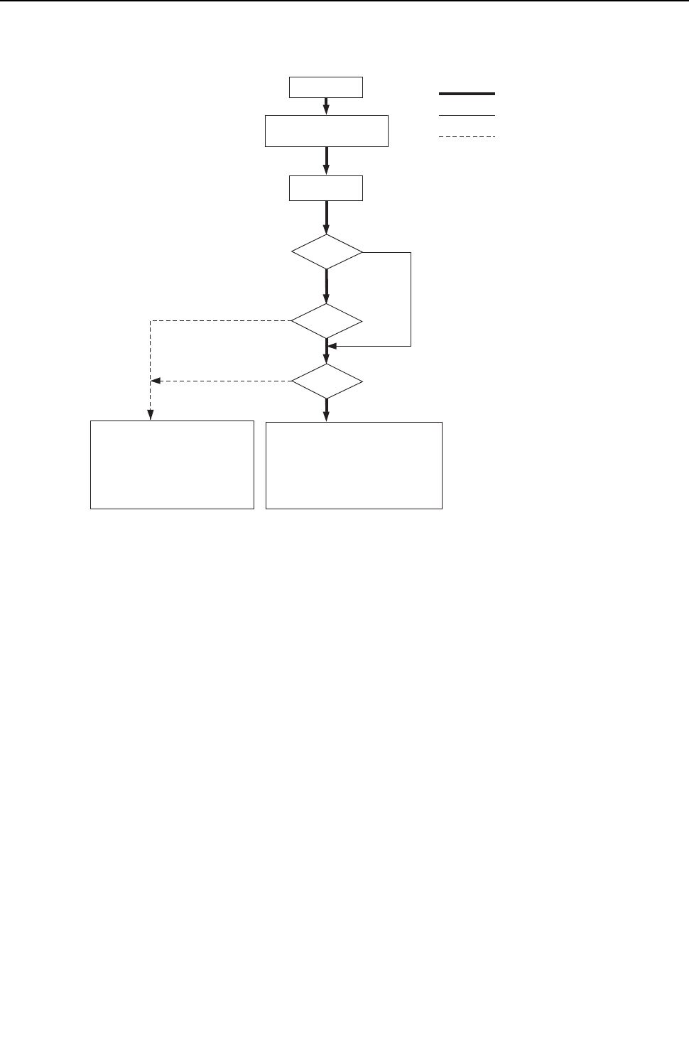
[ VII Control ]
- 169 -
HWE09080 GB
2. Operations in each mode
(1) Cooling operation
Cooling operation
Test run mode
ON
Thermostat
ON
3-minute restart
prevention
*Note 1
YES
YES
YES
NO
NO
NO
4-way valve OFF
1. Inverter frequency control
2.
Indoor unit LEV, Oil returnLEV control
3. Solenoid valve control
4. BC controller solenoid valve control
5. BC controller control
Normal operation
During test run mode
Indoor unit fan
operation
1. Inverter output 0Hz
2.
Indoor unit LEV, Oil return LEV fully closed
3. Solenoid valves OFF
4. BC controller solenoid valves OFF
5. BC controller LEV fully closed
Unit in the stopped state
*Note 1. The indoor fan operates at the set notch under cooling mode regardless of the
ON/OFF state of the thermostat.
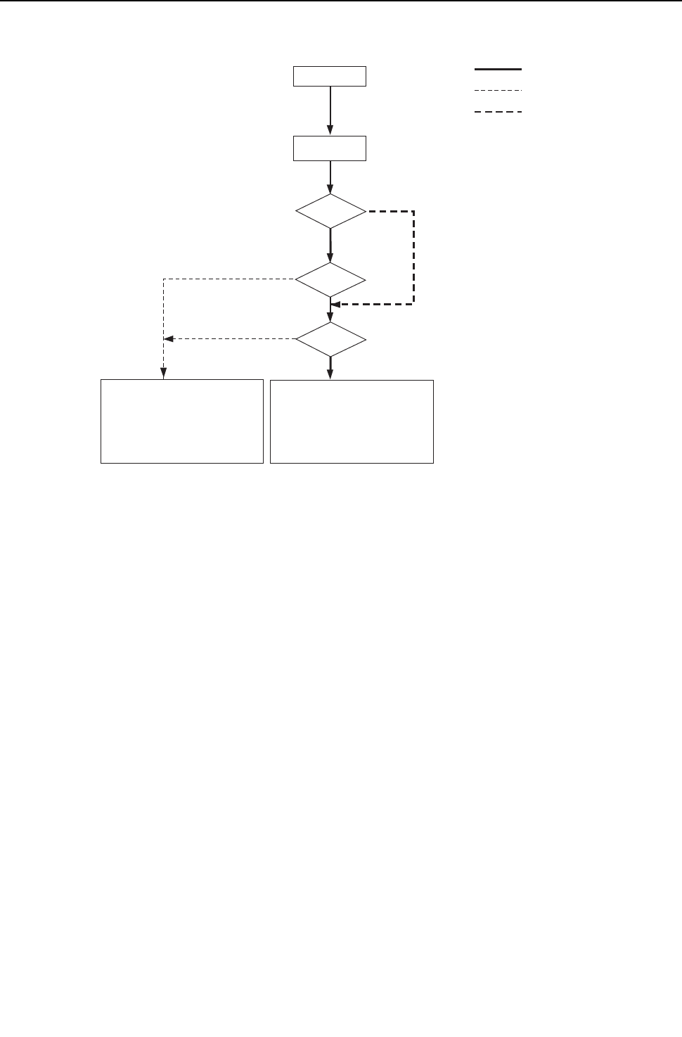
[ VII Control ]
- 170 -
HWE09080 GB
(2) Heating operation
Heating operation
Test run mode
ON
Thermostat
ON
3-minute restart
prevention
YES
YES
YES
NO
NO
NO
1. Indoor-heat source unit fan control
2. Inverter frequency control
3. Indoor unit LEV fully open
4. Solenoid valve control
5. BC controller solenoid valve control
6. BC controller LEV control
Normal operation
4-way valve ON
During test run mode
1. Indoor unit fan operation at
Very Low speed
2. Inverter output 0Hz
3. Indoor unit LEV fully open
4. Solenoid valve OFF
5. BC controller solenoid valve control
6. BC controller LEV control
Unit in the stopped state
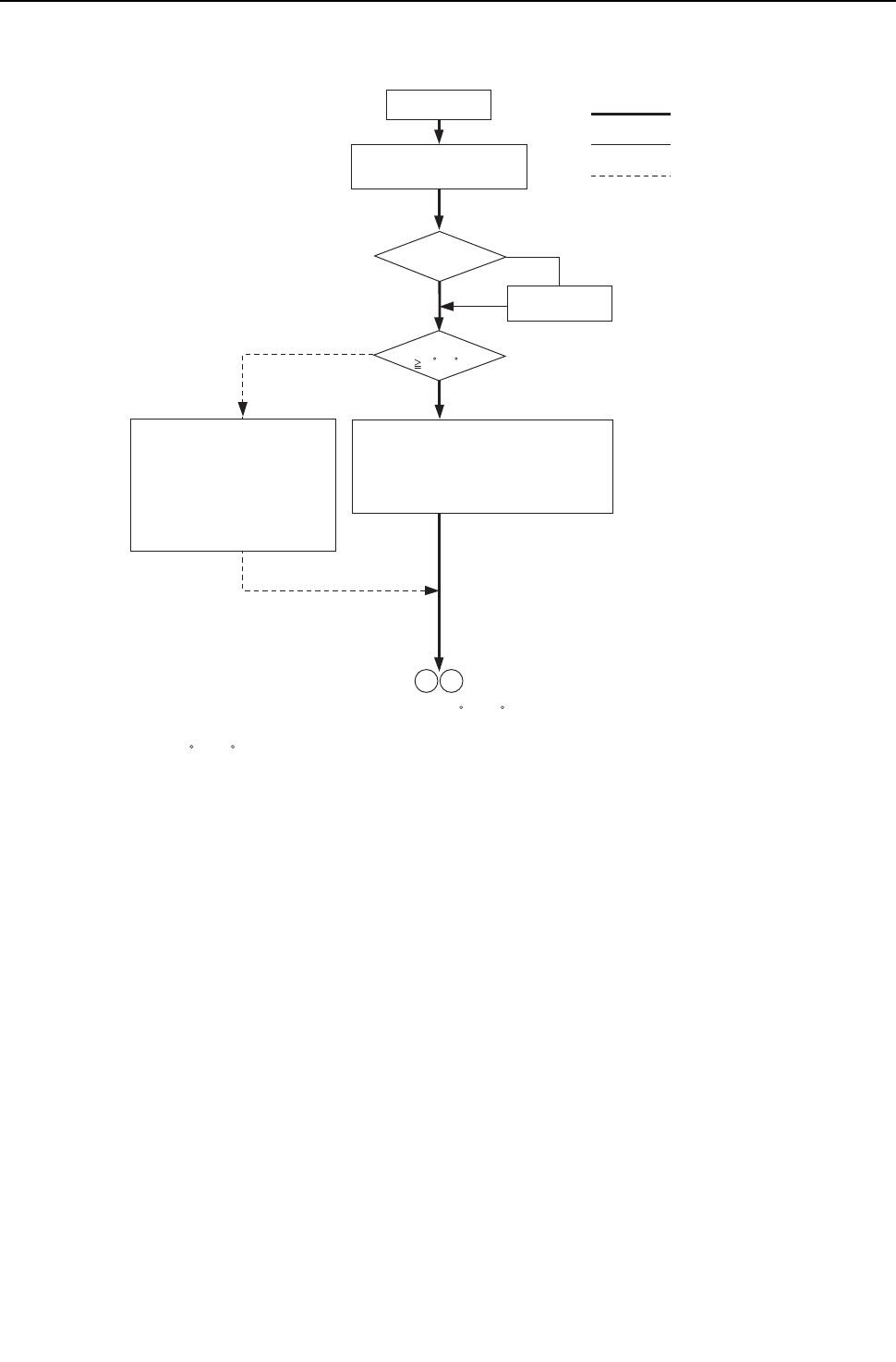
[ VII Control ]
- 171 -
HWE09080 GB
(3) Dry operation
Dry operation
*Note 1
*Note 2
YES
YES
NO
NO
4-way valve OFF
1. Heat source unit (compressor)
intermittent operation
2. Indoor unit fan intermittent operations
(Synchronized with the compressor:
low speed, OFF operations)
Normal operation
Thermostat ON
Thermostat ON
1. Indoor unit fan stop
2. Inverter output 0Hz
3. Indoor unit LEV fully closed.
4. Solenoid valve OFF
5.
BC controller Solenoid valve OFF
6. BC controller
LEV fully closed
1 2
*Note 1.When the indoor unit inlet temperature exceeds 18 C [64 F], the heat source unit (compressor) and the
indoor unit fan start the intermittent operation simultaneously. When the indoor unit inlet temperature
becomes 18 C [64 F],or less, the fan always runs (at low speed). The heat source unit, the indoor unit,
and the solenoid valve operate in the same way as they do in the cooling operation when the compressor
is turned on.
*Note 2.
Thermostat is always kept on during test run mode, and indoor and heat source unit intermittent operation
(ON) time is a little longer than that of normal operation.
Test run mode
ON
Suction temperature
18 C[64 F]
Unit in the stopped state

- 172 -
[ VII Control ]
GBHWE09080

- 173 -
HWE09080 GB
VIII
Test Run Mode
[1] Items to be checked before a Test Run......................................................................... 175
[2] Test Run Method ........................................................................................................... 176
[3] Operating Characteristic and Refrigerant Amount ......................................................... 177
[4] Adjusting the Refrigerant Amount .................................................................................. 177
[5] Refrigerant Amount Adjust Mode................................................................................... 182
[6] The following symptoms are normal. ............................................................................. 186
[7] Standard Operation Data (Reference Data) ..................................................................187

- 174 -
[ VIII Test Run Mode ]
- 175 -
HWE09080 GB
VIII Test Run Mode
[1] Items to be checked before a Test Run
(1) Check for refrigerant leak and loose cables and connectors.
(2) Measure the insulation resistance between the power supply terminal block and the ground with a 500V megger and
make sure it reads at least 1.0Mohm.
Do not operate the unit if the insulation resistance is below 1.0Mohm.
Do not apply megger voltage to the terminal block for transmission line. Doing so will damage the controller board.
The insulation resistance between the power supply terminal block and the ground could go down to close to 1Mohm imme-
diately after installation or when the power is kept off for an extended period of time because of the accumulation of refrigerant
in the compressor.
If insulation resistance reads at least 1Mohm, by turning on the main power and powering the crankcase heater for at least
12 hours, the refrigerant in the compressor will evaporate and the insulation resistance will go up.
Do not measure the insulation resistance of the terminal block for transmission line for the unit remote controller.
(3) Check that the valve on the gas pipe and liquid pipe are fully open.
Securely tighten the cap.
(4) Check the phase sequence and the voltage of the power supply.
(5) [When a transmission booster is connected]
Turn on the transmission booster before turning on the heat source units.
If the heat source units are turned on first, the connection information for the refrigerant circuit may not be properly recognized.
In case the heat source units are turned on before the transmission booster is turned on, perform a power reset on the heat
source units after turning on the power booster.
(6) Turn on the main power to the unit at least 12 hours before test run to power the crankcase heater.
Insufficient powering time may result in compressor damage.
(7) When a power supply unit is connected to the transmission line for centralized control, perform a test run with the
power supply unit being energized. Leave the power jumper connector on CN41 as it is (factory setting).
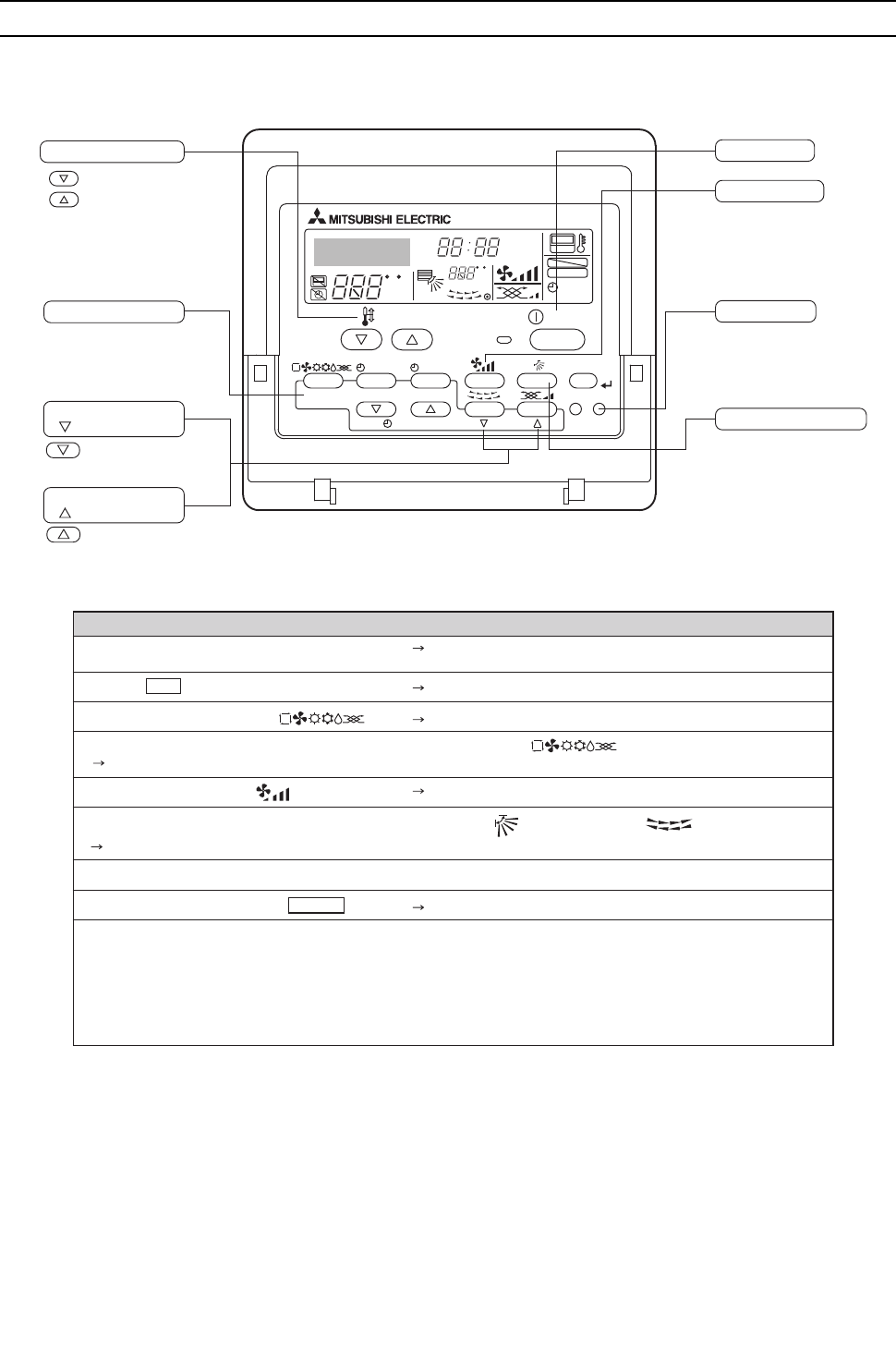
[ VIII Test Run Mode ]
- 176 -
HWE09080 GB
[2] Test Run Method
The figure shows an MA remote controller (PAR-21MAA).
PAR-21MAA
ON/OFF
FILTER
CHECK
OPERATION
CLEAR
TEST
TEMP.
MENU
BACK DAY
MONITOR/SET
CLOCK
ON/OFF
Set Temperature buttons
Down
Up
Operation Mode button
ON/OFF button
Fan Speed button
Test Run button
Vertical Air Direction button
Louver button
(
Operation button)
To preceding
operation number.
Ventilation button
( Operation button)
To next operation
number.
FC
FC
ERROR CODE
AFTER
TIMER
TIME SUN MON TUE WED THU FRI SAT
ON
OFF
Hr
AFTER
FILTER
FUNCTION
ONLY1Hr.
WEEKLY
SIMPLE
AUTO OFF
Operation procedures
Turn on the main power. "PLEASE WAIT" appears on the LCD for up to five minutes. Leave
the power on for 12 hours. (Energize the crankcase heater.)
Press the Test button twice.
Operation mode display "TEST RUN" and OPERATION MODE are
displayed alternately.
Press the Operation Mode button.
Make sure that cold (or warm) air blows out.
Make sure that the air is blowing out.
Switch to cooling (or heating) operation by pressing the Operation Mode button.
Press the Fan Speed button.
Change the air flow direction by pressing the Vertical Air Direction button or the Louver button.
Confirm the operation of all interlocked equipment, such as ventilation equipment.
Note 1: Refer to the following pages if an error code appears on the remote controller or when the unit malfunctions.
2: The OFF timer will automatically stop the test run after 2 hours.
3: The remaining time for the test run will be displayed in the time display during test run.
4: The temperature of the liquid pipe on the indoor unit will be displayed in the room temperature display window on the remote
controller during test run.
5: On some models, "NOT AVAILABLE" may appear on the display when the Vane Control button is pressed. This is normal.
6: If an external input is connected, perform a test run using the external input signal.
7:
Perform simultaneous all-system operation for 15 minutes or longer because system error detection may take 15 minutes maximum.
Make sure that the fan speed changes with each pressing of the button.
Stop
Make sure that the air flow direction changes with each pressing of the button.
Cancel the test run by pressing the ON/OFF button.
[ VIII Test Run Mode ]
- 177 -
HWE09080 GB
[3] Operating Characteristic and Refrigerant Amount
It is important to have a clear understanding of the characteristics of refrigerant and the operating characteristics of air conditioners
before attempting to adjust the refrigerant amount in a given system.
1. Operating characteristic and refrigerant amount
The following table shows items of particular importance.
1) During cooling operation, the amount of refrigerant in the accumulator is the smallest when all indoor units are in operation.
2) During heating operation, the amount of refrigerant in the accumulator is the largest when all indoor units are in operation.
3) General tendency of discharge temperature
Discharge temperature tends to rise when the system is short on refrigerant.
Changing the amount of refrigerant in the system while there is refrigerant in the accumulator has little effect on the discharge
temperature.
The higher the pressure, the more likely it is for the discharge temperature to rise.
The lower the pressure, the more likely it is for the discharge temperature to rise.
4) When the amount of refrigerant in the system is adequate, the compressor shell temperature is 10 to 60°C [18 to 108°F] higher
than the low pressure saturation temperature (Te).
-> If the temperature difference between the compressor shell temperature and low pressure saturation temperature (Te) is
smaller than 5°C [9°F], an overcharging of refrigerant is suspected.
[4] Adjusting the Refrigerant Amount
1. Symptoms
Overcharging or undercharging of refrigerant can cause the following symptoms:
Before attempting to adjust the amount of refrigerant in the system, thoroughly check the operating conditions of the system.
Then, adjust the refrigerant amount by running the unit in the refrigerant amount adjust mode.
2. Amount of refrigerant
(1) To be checked during operation
Operate all indoor units in either cooling-only or heating-only mode, and check such items as discharge temperature, subcool-
ing, low pressure, suction temperature, and shell bottom temperature to estimate the amount of refrigerant in the system.
The system comes to an abnormal stop, displaying 1500 (overcharged refrigerant) on
the controller.
Overcharged refrigerant
The operating frequency does not reach the set frequency, and there is a problem with
performance.
Insufficient refrigerant amount
The system comes to an abnormal stop, displaying 1102 (abnormal discharge temper-
ature) on the controller.
Symptoms Conclusion
Discharge temperature is high. (Normal discharge temperature is below 95°C [203°F].) Slightly under-
charged refrigerant
Low pressure is unusually low.
Suction superheat is large. (Normal suction superheat is less than 20°C [36°F].)
Compressor shell bottom temperature is high. (The difference between the compressor shell
bottom temperature and low pressure saturation temperature (Te) is greater than 60°C [108°F].)
Discharge superheat is small. (Normal discharge superheat is greater than 10°C [18°F].) Slightly overcharged
refrigerant
Compressor shell bottom temperature is low. (The difference between the compressor shell bot-
tom temperature and low pressure saturation temperature (Te) is less than 5°C [9°F].)
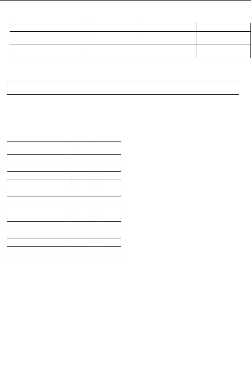
[ VIII Test Run Mode ]
- 178 -
HWE09080 GB
3. Amount of refrigerant to be added<PQHY>
The amount of refrigerant that is shown in the table below is factory-charged to the heat source units.
The amount necessary for extended pipe (field piping) is not included and must be added on site.
(1) Calculation formula
The amount of refrigerant to be added depends on the size and the length of field piping. (unit in m[ft])
Round up the calculation result to the nearest 0.1kg. (Example: 18.04kg to 18.1kg)
Round up the calculation result in increments of 4oz (0.1kg) or round it up to the nearest 1oz.
(Example: 178.21Q\ to 179oz)
Heat source unit model P72 P96 P120
Amount of pre-charged refrigerant in
the heat source unit (kg) 5.0 5.0 5.0
Amount of pre-charged refrigerant in
the heat source unit [lbs] 11.0 11.0 11.0
Amount of added refrigerant (kg) = (0.29x L1) + (0.2 x L2) + (0.12 x L3) + (0.06 x L4) + (0.024 x L5) +ǩ
Amount of added refrigerant (oz) = (3.12x L1' ) +(2.15 x L2' ) + (1.29 x L3' ) + (0.65 x L4' ) + (0.26 x L5' ) + ǩ
L1 : Length of ø19.05 [3/4"] liquid pipe (m)
L2 : Length of ø15.88 [5/8"] liquid pipe (m)
L3 : Length of ø12.7 [1/2"] liquid pipe (m)
L4 : Length of ø9.52 [3/8"] liquid pipe (m)
L5 : Length of ø6.35 [1/4"] liquid pipe (m)
ǩ, ǩ' : Refer to the table below.
L1' : Length of ø19.05 [3/4"] liquid pipe [ft]
L2' : Length of ø15.88 [5/8"] liquid pipe [ft]
L3' : Length of ø12.7 [1/2"] liquid pipe [ft]
L4' : Length of ø9.52 [3/8"] liquid pipe [ft]
L5' : Length of ø6.35 [1/4"] liquid pipe [ft]
Total capacity of
connected indoor units ǩ(kg) ǩ'(oz)
-27 2.0 71
28 - 54 2.5 89
55 - 126 3.0 106
127 - 144 3.5 124
145 - 180 4.5 159
181 - 234 5.0 177
235 - 273 6.0 212
274 - 307 8.0 283
308 - 342 9.0 318
343 - 411 10.0 353
412 - 480 12.0 424
481 - 14.0 494
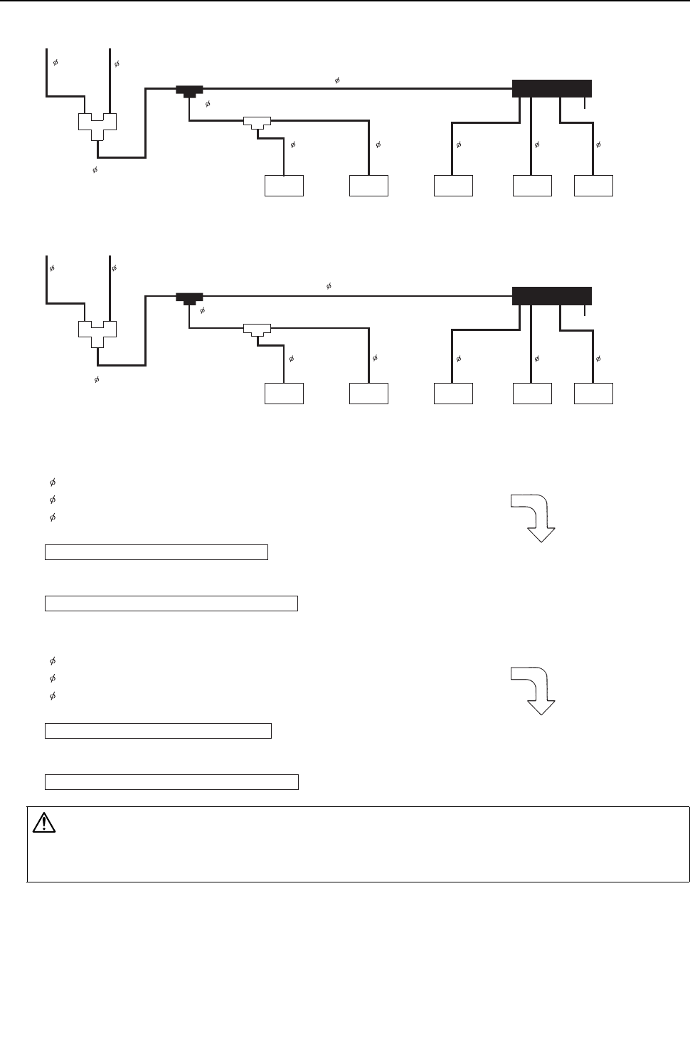
[ VIII Test Run Mode ]
- 179 -
HWE09080 GB
(2) Example: PQHY-P144TSHMU-A/YSHMU-A
(3) Sample calculation
CAUTION
Charge liquid refrigerant (as opposed to gaseous refrigerant) into the system.
If gaseous refrigerant is charged into the system, the composition of the refrigerant in the cylinder will change and may
result in performance loss.
[3/4"][98 ft]
[3/4"] [32 ft]
[3/8"][32 ft]
9.52
(20 m)
9.52
(10 m)
9.52
(10 m)
9.52
(10 m)
6.35
(10 m)
9.52 (10 m)
[3/8"]
[32 ft]
[3/8"]
[3 ft]
[3/8"]
[9 ft]
[3/8"]
[32 ft]
[1/4"]
[32 ft]
[3/8"]
[32 ft]
[3/8"]
[65 ft]
15.88 (10 m)
15.88 (30 m)
9.52
(3 m)
9.52
(1 m)
×
×
96
model 48
model 30
model 24
model 06
model
96
model 48
model 30
model 24
model 06
model
Liquid
separator
Liquid
separator
All the pipes in the figure are liquid pipes.
15.88 : 30 m + 10 m = 40 m
9.52 : 3 m + 1m + 10 m + 10 m + 20 m + 10 m + 10 m = 64 m
6.35 : 10 m
According to the above formula
The calculation result would be 17.08, and it is rounded up to the nearest 0.1.
The final result will be as follows:
Amount of refrigerant to be charged (kg) = (0.2 X 40) + (0.06 X 64) + (0.024 X 10) + 5.0 = 17.08kg
Amount of refrigerant to be charged = 17.1kg
All the pipes in the figure are liquid pipes.
[3/4"] : [98 ft] + [32 ft] = [130 ft]
[3/8"] : [9 ft] + [3 ft] + [32 ft] + [32 ft] + [65 ft] + [32 ft] + [32 ft] = [205 ft]
[1/4"] : [32 ft]
According to the above formula
The calculation result would be 598.07 oz, and it is rounded up to the nearest 1 oz.
The final result will be as follows:
Amount of refrigerant to be charged (oz) = (2.15 X 130) + (0.65 X 205) + (0.26 X 32) + 177 = 598.07oz
Amount of refrigerant to be charged = 599 oz
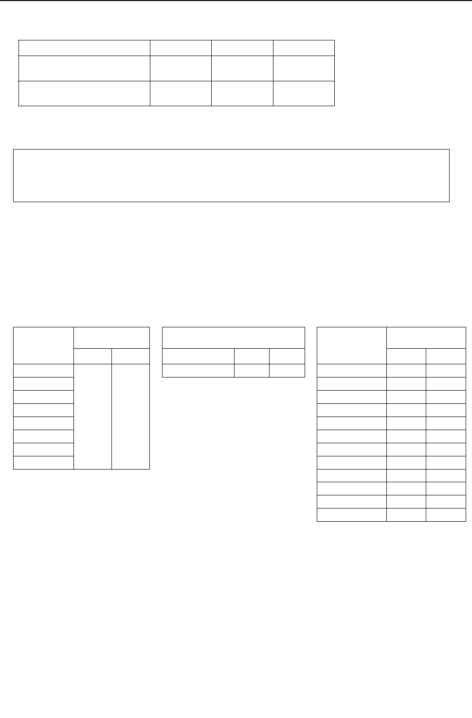
[ VIII Test Run Mode ]
- 180 -
HWE09080 GB
4. Amount of refrigerant to be added <PQRY>
The amount of refrigerant that is shown in the table below is factory-charged to theheat source units.
The amount necessary for extended pipe (field piping) is not included and must be added on site.
(1) Calculation formula
The amount of refrigerant to be added depends on the size and the length of field piping. (unit in m[ft])
Round up the calculation result to the nearest 0.1kg. (Example: 18.04kg to 18.1kg)
Round up the calculation result in increments of 4oz (0.1kg) or round it up to the nearest 1oz. (Example: 78.21oz to 79oz)
Heat source unit model P72 P96 P120
Amount of pre-charged refrigerant
in the heat source unit (kg) 5.0 5.0 5.0
Amount of pre-charged refrigerant
in the heat source unit [lbs] 11.0 11.0 11.0
Amount of added refrigerant (kg) = (0.36 x L1) + (0.23 x L2) + (0.16 x L3) + (0.11 x L4)+ (0.2 x L5)
+ (0.12 x L6) + (0.06 x L7) + (0.024 x L8) + ǩ1 + ǩ2 + ǩ3 + ǩ4
Amount of added refrigerant (oz) = (3.88 x L1' ) + (2.48 x L2' ) + (1.73 x L3' ) + (1.19 x L4' )+ (2.16 x L5' )
+ (1.30 x L6' ) + (0.65 x L7' ) + (0.26 x L8' ) + ǩ1' + ǩ2' + ǩ3' + ǩ4'
L1 : Length of ø28.58[1-1/8"] high pressure pipe (m)
L2 : Length of ø22.2[7/8"] high pressure pipe (m)
L3 : Length of ø19.05[3/4"] high pressure pipe (m)
L4 : Length of ø15.88[5/8"] high pressure pipe (m)
L5 : Length of ø15.88[5/8"] liquid pipe (m)
L6 : Length of ø12.7[1/2"] liquid pipe (m)
L7 : Length of ø9.52[3/8"] liquid pipe (m)
L8 : Length of ø6.35[1/4"] liquid pipe (m)
ǩ1,ǩ2,ǩ3,ǩ4, ǩ1' , ǩ2' , ǩ3' , ǩ4' : Refer to the table
below.
L1' : Length of ø28.58[1-1/8"] high pressure pipe [ft]
L2' : Length of ø22.2[7/8"] high pressure pipe [ft]
L3' : Length of ø19.05[3/4"] high pressure pipe [ft]
L4' : Length of ø15.88[5/8"] high pressure pipe [ft]
L5' : Length of ø15.88[5/8"] liquid pipe [ft]
L6' : Length of ø12.7[1/2"] liquid pipe [ft]
L7' : Length of ø9.52[3/8"] liquid pipe [ft]
L8' : Length of ø6.35[1/4"] liquid pipe [ft]
Heat source unit
total index
Amount for the BC
controllers (main/sub) BC controller (sub) Total capacity of
connected indoor
units
Amount for the Indoor
unit
ǩ1(kg) ǩ1' (oz) 11.0 35 ǩ4(kg) ǩ4' (oz)
P72
3.0 106
2 2.0 71 - 27 2.0 71
P96 28 - 54 2.5 89
P120 55 - 126 3.0 106
P144 127 - 144 3.5 124
P168 145 - 180 4.5 159
P192 181 - 234 5.0 177
P216 235 - 273 6.0 212
P240 274 - 307 8.0 283
308 - 342 9.0 318
343 - 411 10.0 353
412 - 480 12.0 424
481 - 14.0 494
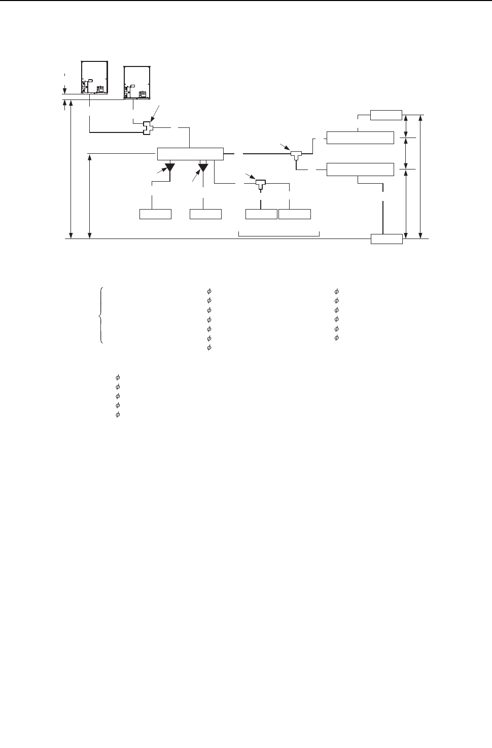
[ VIII Test Run Mode ]
- 181 -
HWE09080 GB
(2) Example
(3) Sample calculation
BC controller
BC controller(HB)
BC controller(HB)
Indoor
a
C
b
HH′
h1 h1
(P06 - P54)
Junction pipe kit
(CMY-R160-J)
(Optional accessory)
Branch joint
(CMY-Y102S-G2)
B
c d
f
h3
D
E
Branch joint
(CMY-Y202-G2)
(CMY-Y102L-G2)
(CMY-Y102S-G2)
Aeh1
F
h4
Branch joint kit
Heat source unit 1
Heat source unit 2
Reducer (P06 - P18)
(Supplied with the BC Controller)
G
h2
Indoor
Indoor
Maximum of 3 units per port
Total capacity of P54 or below
Indoor IndoorIndoor
2
6
5
341
(P72 or P96)
Indoor unit1:30 model
Indoor unit2:96 model
Indoor unit3:12 model
Indoor unit4:15 model
Indoor unit5:12 model
Indoor unit6:24 model
A : 28.58
B : 9.52
C : 9.52
D : 9.52
E : 9.52
F : 22.2
G : 19.05
40m
10m
20m
5m
5m
3m
1m
[1-1/8"]
[3/8"]
[3/8"]
[3/8"]
[3/8"]
[7/8"]
[3/4"]
[3/8"]
[3/8"]
[1/4"]
[1/4"]
[1/4"]
[3/8"]
[131ft]
[32ft]
[65ft]
[16ft]
[16ft]
[9ft]
[3ft]
[32ft]
[16ft]
[16ft]
[32ft]
[16ft]
[16ft]
a : 9.52
b : 9.52
c : 6.35
d : 6.35
e : 6.35
f : 9.52
10m
5m
5m
10m
5m
5m
28.58 A = 40m[131ft]
22.2 F = 30m[98ft]
19.05 G = 1m[3ft]
9.52 C+D+E+a+b+f = 50m[164ft]
6.35 c+d+e = 20m[65ft]
The aggregate length of each liquid pipe type.
The final result will be as follows:
Amount of refrigerant to be charged = 40×0.36+3×0.23+1×0.16+50×0.06+20×0.024+7.5+2+2+5
= 35.3kg
When
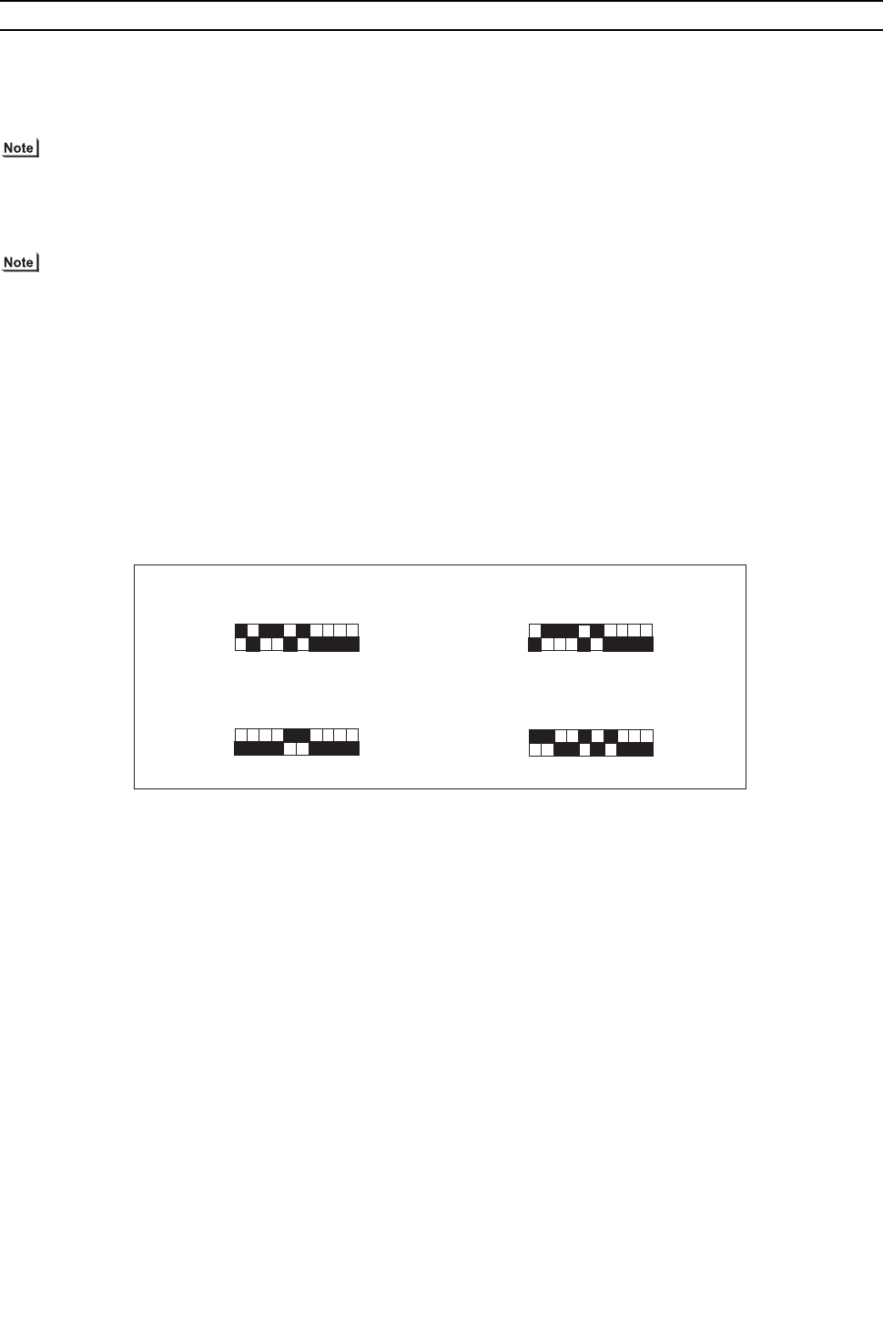
[ VIII Test Run Mode ]
- 182 -
HWE09080 GB
[5] Refrigerant Amount Adjust Mode
1. Procedures <PQHY>
Follow the procedures below to add or extract refrigerant as necessary depending on the operation mode.
When the function switch (SW4-3) on the main board on the heat source unit (OC only) is turned to ON, the unit goes into the
refrigerant amount adjust mode, and the following sequence is followed.
SW4-3 on the OS is invalid, and the unit will not go into the refrigerant amount adjust mode.
Operation
When the unit is in the refrigerant amount adjust mode, the LEV on the indoor unit does not open as fully as it nor-
mally does during cooling operation to secure subcooling.
1) Adjust the refrigerant amount based on the values of TH4, TH3, TH6, and Tc, following the flowchart below. Check the TH4,
TH3, TH6, and Tc values on the OC, OS1, and OS2 by following the flowchart. The TH4, TH3, TH6, and Tc values can be
displayed by setting the self-diagnosis switch (SW1) on the main board on the OC, OS1, and OS2.
2) There may be cases when the refrigerant amount may seem adequate for a short while after starting the unit in the refrigerant
amount adjust mode but turn out to be inadequate later on (when the refrigerant system stabilizes).
When the amount of refrigerant is truly adequate.
TH3-TH6 on the heat source unit is 5°C [9°F] or above and SH on the indoor unit is between 5 and 15°C [9 and 27°F].
The refrigerant amount may seem adequate at the moment, but may turn out to be inadequate later on.
TH3-TH6 on the heat source unit is 5°C [9°F] or less and SH on the indoor unit is 5°C [9°F] or less.
Wait until the TH3-TH6 reaches 5°C [9°F] or above and the SH of the indoor unit is between 5 and 15°C [9 and 27°F] to
determine that the refrigerant amount is adequate.
3) High pressure must be at least 2.0MPa[290psi] to enable a proper adjustment of refrigerant amount to be made.
4) Refrigerant amount adjust mode automatically ends 90 minutes after beginning. When this happens, by turning off the SW4-
3 and turning them back on, the unit will go back into the refrigerant amount adjust mode.
Self-diagnosis swithes on TH4
Self-diagnosis swithes on TH6
Self-diagnosis swithes on TH3
Self-diagnosis swithes on Tc
1 2 3 4 5 6 7 8 9 10
ON
1 2 3 4 5 6 7 8 9 10
ON
1 2 3 4 5 6 7 8 9 10
ON
1 2 3 4 5 6 7 8 9 10
ON
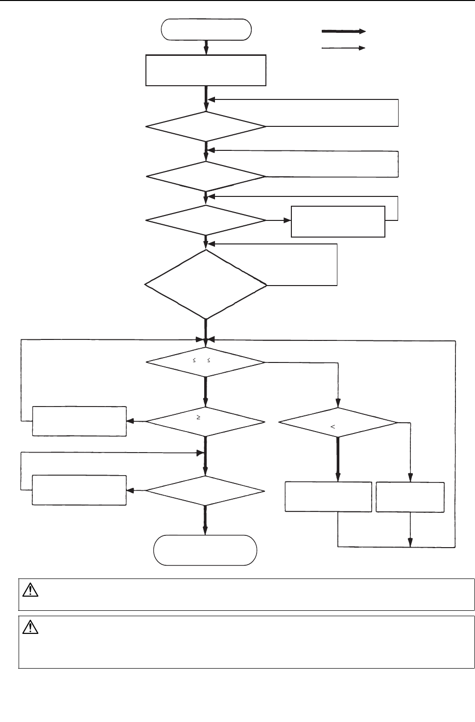
[ VIII Test Run Mode ]
- 183 -
HWE09080 GB
CAUTION
Do not release the extracted refrigerant into the air.
CAUTION
Charge liquid refrigerant (as opposed to gaseous refrigerant) into the system.
If gaseous refrigerant is charged into the system, the composition of the refrigerant in the cylinder will change and may
result in performance loss.
YES
YES
YES
YES
YES
YES
YES
YES
YES
NO
NO
NO
NO
NO
NO
NO
NO
NO
Start
Put all indoor units in the test run mode
and run the units in cooling mode.
Has it been at least
30 minutes since
start up?
Note 3
Note 1
Does 8°C [14.4°F] Tc-TH3 12°C [21.6°F] hold true?
(Use the largest “Tc - TH3” value of the
OC, OS1, and OS2.)
Does the following hold true?
Tc-TH3 8°C [14.4°F]
*Refer to the previous page for *Notes 1-4 in the chart.
Note 2
Note 2
Note 2
Note 1
Gradually add refrigerant from
the service port on the low-
pressure side.
Keep the unit running for 5 minutes after
adjusting the refrigerant amount to
determine its adequacy.
Keep the unit running for 5 minutes after adjusting the
refrigerant amount to determine its adequacy.
Turn off SW4-3 on the OC.
Turn on SW4-3 on the OC.
Adjustment complete
Note 4
Has the initial start-up
mode been completed?
Gradually add refrigerant from
the service port on the low
pressure side.
Gradually add refrigerant from
the service port on the low
pressure side.
Keep the unit running for 5 minutes
after adjusting the refrigerant amount
and check(Tc-TH3)
Gradually add refrigerant from
the service port on the low
pressure side.
Gradually draw out
refrigerant from the service
port on the low pressure side.
Does Tc-TH6 20°C [36°F] hold true?
Is the TH4 value of the OC, OS1,
OS2 at or below 100°C [212°F]?
Has the operating frequency
of the compressor on the OC, OS1,
and OS2 become stable?
Note 1
Is the TH4 value of the OC, OS1,
OS2 at or below 95°C [203°F]
(Check this item on the unit whose “Tc – TH3” value was
used in the step above.)
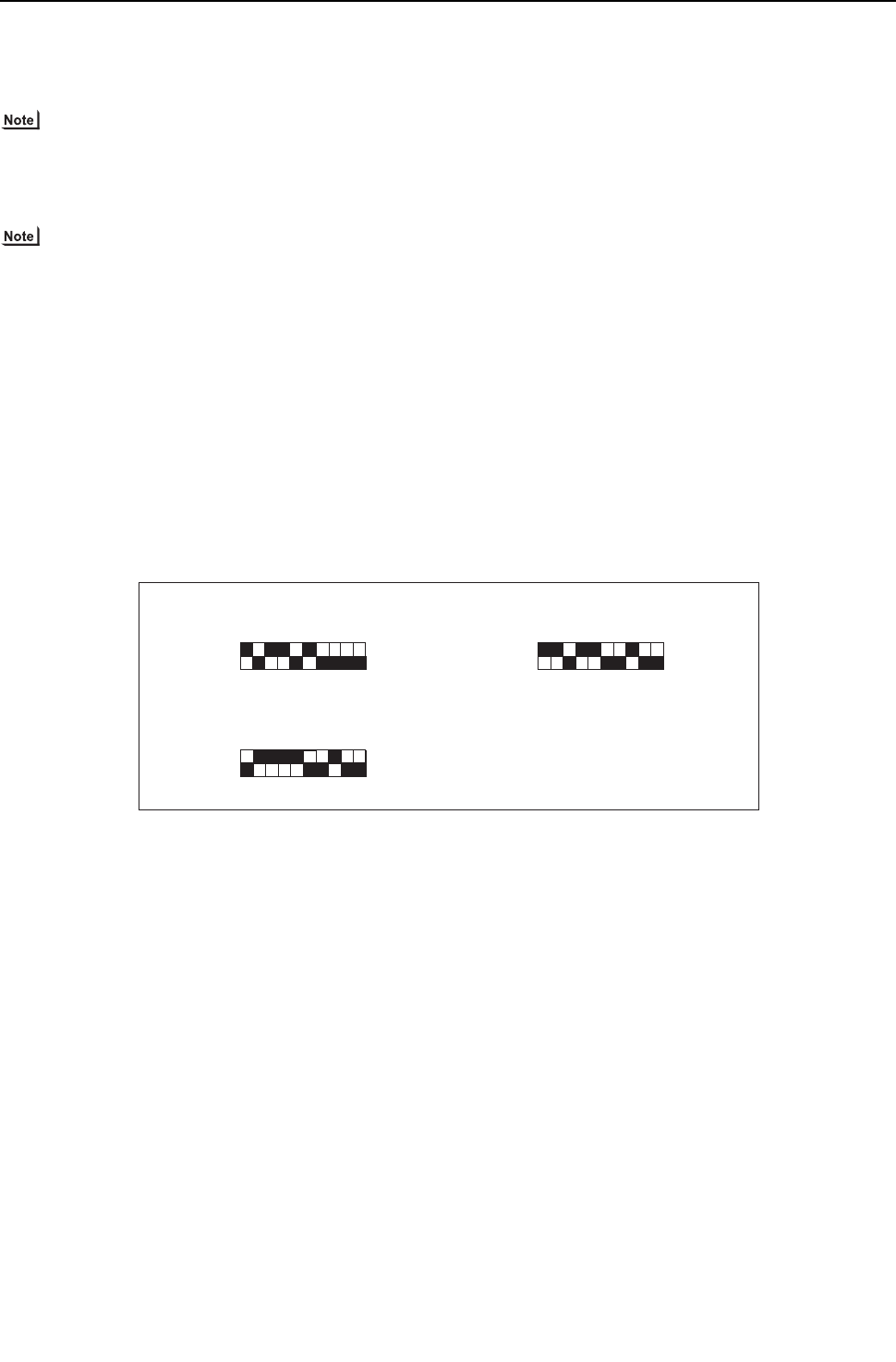
[ VIII Test Run Mode ]
- 184 -
HWE09080 GB
2. Procedures <PQRY>
Follow the procedures below to add or extract refrigerant as necessary depending on the operation mode.
When the function switch (SW4-3) on the main board on the heat source unit (OC only) is turned to ON, the unit goes into the
refrigerant amount adjust mode, and the following sequence is followed.
SW4-3 on the OS is invalid, and the unit will not go into the refrigerant amount adjust mode.
Operation
When the unit is in the refrigerant amount adjust mode, the LEV on the indoor unit does not open as fully as it nor-
mally does during cooling operation to secure subcooling.
1) Adjust the refrigerant amount based on the TH4 value, following the flowchart below. Check the TH4, SC11, SC16, and Tc
values on the OC, OS by following the flowchart. The TH4, SC11, and SC16 values can be displayed by setting the self-diag-
nosis switch (SW1) on the main board on the OC, OS.
2) There may be cases when the refrigerant amount may seem adequate for a short while after starting the unit in the refrigerant
amount adjust mode but turn out to be inadequate later on (when the refrigerant system stabilizes).
When the amount of refrigerant is truly adequate.
Subcool (SC11 and SC16) of the BC controller is 5°C [9°F] or above and SH on the indoor unit is between 5 and 15°C [9 and
27°F].
The refrigerant amount may seem adequate at the moment, but may turn out to be inadequate later on.
Subcool (SC11 and SC16) of the BC controller is 5°C [9°F] or less and SH on the indoor unit is 5°C [9°F] or less.
Wait until the Subcool (SC11 and SC16) of the BC controller reaches 5°C [9°F] or above and the SH of the indoor unit is be-
tween 5 and 15°C [9 and 27°F] to determine that the refrigerant amount is adequate.
SC11: Subcool of liquid refrigerant at BC controller inlet; SC16: Subcool of liquid refrigerant at BC controller outlet
3) High pressure must be at least 2.0MPa [290psi] to enable a proper adjustment of refrigerant amount to be made.
4) Refrigerant amount adjust mode automatically ends 90 minutes after beginning. When this happens, by turning off the SW4-
3 and turning them back on, the unit will go back into the refrigerant amount adjust mode.
Self-diagnosis swithes on TH4
Self-diagnosis swithes on SC16
Use these switches to check the TH4, SC11, and SC16.
Self-diagnosis swithes on SC11
ON ON
1 2 3 4 5 6 7 8 9 10 1 2 3 4 5 6 7 8 9 10
1 2 3 4 5 6 7 8 9 10
ON
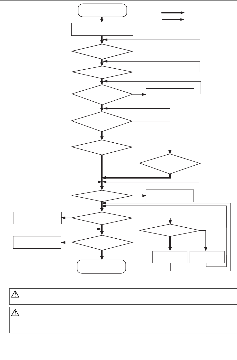
[ VIII Test Run Mode ]
- 185 -
HWE09080 GB
CAUTION
Do not release the extracted refrigerant into the air.
CAUTION
Charge liquid refrigerant (as opposed to gaseous refrigerant) into the system.
If gaseous refrigerant is charged into the system, the composition of the refrigerant in the cylinder will change and may
result in performance loss.
Start
Turn on SW4-3 on the OC.
YES
YES
YES
YES
YES
YES
YES
YES
YES
YES
YES
NO
NO
NO
NO
NO
NO
NO
NO
NO
NO
NO
Put all indoor units in the test run mode
and run the units in cooling mode.
Has it been at least
30 minutes since
start up?
Note 3
*Refer to the previous page for *Notes 1-4 in the chart.
Note 2
Note 2
Note 2
Gradually add refrigerant from
the service port on the low-
pressure side.
Keep the unit running for 5 minutes after
adjusting the refrigerant amount to
determine its adequacy.
Keep the unit running for 5 minutes after adjusting the
refrigerant amount to determine its adequacy.
Note 2
5K[41°F] ≤ SC11?
Turn off SW4-3 on the OC.
Adjustment complete
Does 10 ≤ SC16 ≤ 30K [86ºF]
hold true?
Note1
Does 10K [50ºF] > SC16
hole true?
Note 4
Has the initial start-up
mode been completed?
Gradually add refrigerant from
the service port on the low
pressure side.
Gradually add refrigerant from
the service port on the low
pressure side.
Keep the unit running for 5 minutes after adjusting the
refrigerant amount and check(Tc-TH3)
Note 2
Keep the unit running for 5 minutes after adjusting the
refrigerant amount and check(Tc-TH3)
Gradually add refrigerant
from the service port on
the low pressure side.
Gradually draw out
refrigerant from the service
port on the low pressure side.
Is the TH4 value of the OC, OS
at or below 100°C [212°F]?
Does SH ≥ 5K [41ºF] hold
true for all indoor units?
Has the indoor unit
LEV opening stabilized?
Note 2
Has the
operating frequency
of the compressor on the OC, OS
become stable?
N
ote
1
Is the TH4 value of the OC, OS
at or below 95°C [203°F]?
Gradually add refrigerant from
the service port on the low
pressure side.

[ VIII Test Run Mode ]
- 186 -
HWE09080 GB
[6] The following symptoms are normal.
Symptoms Remote controller
display Cause
The indoor unit does not start
after starting cooling (heating)
operation.
"Cooling (heating)"
icon blinks on the
display.
The unit cannot perform a heating (cooling) operation when other indoor
units are performing a cooling (heating) operation.
The auto vane adjusts its posi-
tion by itself.
Normal display
After an hour of cooling operation with the auto vane in the vertical posi-
tion, the vane may automatically move into the horizontal position.
Louver blades will automatically move into the horizontal position while
the unit is in the defrost mode, pre-heating stand-by mode, or when the
thermostat triggers unit off.
The fan keeps running after
the unit has stopped. Unlit When the auxiliary heater is turned on, the fan operates for one minute
after stopping to dissipate heat.
The fan speed does not reach
the set speed when operation
switch is turned on. STAND BY
The fan operates at extra low speed for 5 minutes after it is turned on or
until the pipe temperature reaches 35°C[95°F], then it operates at low
speed for 2 minutes, and finally it operates at the set speed.
(Pre-heating stand-by)
When the main power is
turned on, the display shown
on the right appears on the in-
door unit remote controller for
5 minutes.
"HO" or "PLEASE
WAIT" icons blink
on the display.
The system is starting up. Wait until the blinking display of "HO" or
"PLEASE WAIT" go off.
The drain pump keeps run-
ning after the unit has
stopped.
Unlit
The drain pump stays in operation for three minutes after the unit in the
cooling mode is stopped.
The drain pump is running
while the unit is stopped.
When drain water is detected, the drain pump goes into operation even
while the unit is stopped.
Indoor unit and BC controller
make noise during cooling/
heating changeover.
Normal display
This noise is made when the refrigerant circuit is reversed and is normal.
Sound of the refrigerant flow is
heard from the indoor unit im-
mediately after starting opera-
tion.
Normal display
This is caused by the transient instability of the refrigerant flow and is nor-
mal.
Warm air sometimes comes
out of the indoor units that are
not in the heating mode. Normal display
This is due to the fact that the LEVs on some of the indoor units are kept
slightly open to prevent the refrigerant in the indoor units that are not op-
erating in the heating mode from liquefying and accumulating in the com-
pressor. It is part of a normal operation.
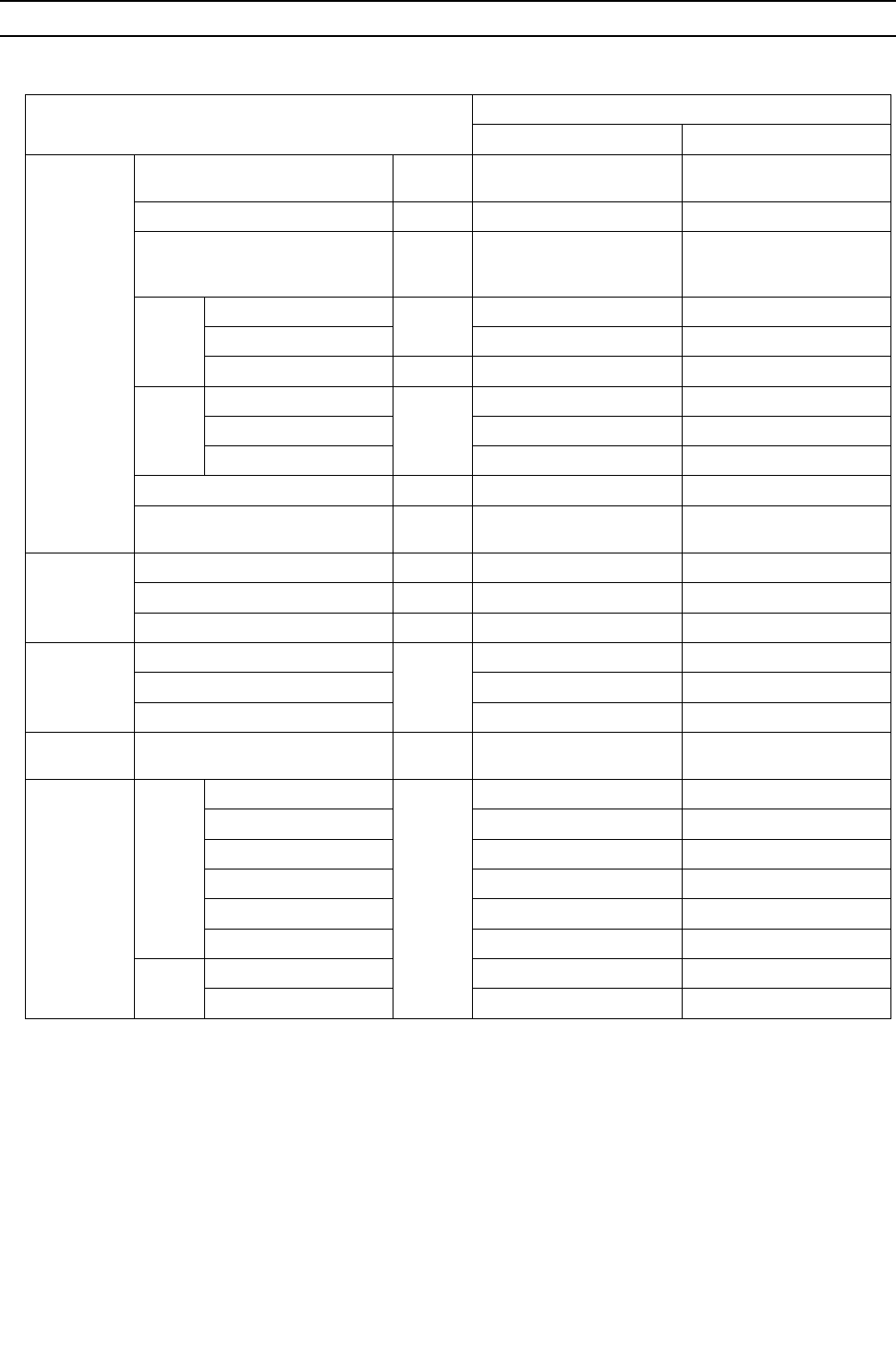
[ VIII Test Run Mode ]
- 187 -
HWE09080 GB
[7] Standard Operation Data (Reference Data)
1. Single unit<PQHY>
(1) Cooling operation
Item
Heat source unit model
PQHY-P72YHMU-A PQHY-P96YHMU-A
Operating
conditions
Indoor temperature DB/WB 26.7°C/19.4°C
[80°F/67°F]
26.7°C/19.4°C
[80°F/67°F]
Heat source water temperature °C [ °F] 29.4[85] 29.4[85]
Heat source water flow rate
m3/h
[G/h]
[gpm]
5.76
[1522]
[25.4]
5.76
[1522]
[25.4]
Indoor
unit
No. of connected units
Unit
22
No. of units in operation 2 2
Model - 36/36 48/48
Pipe
length
Main pipe
m [ft]
5 [16-3/8 ] 5 [16-3/8 ]
Branch pipe 10 [32-3/4 ] 10 [32-3/4 ]
Total pipe length 25 [82] 25 [82]
Fan speed - Hi Hi
Refrigerant charge kg
[lbs-oz] 11.8 [27] 13.0 [29]
Heat source
unit
Current A 17.7 23.3
Voltage V 230 230
Compressor frequency Hz 66 90
LEV opening
Indoor unit
Pulse
325/325 387/387
SC (LEV1) 80 100
LEV2 1400 1400
Pressure
switch
High pressure (after O/S)/
Low pressure (before accumulator)
MPa
[psi] 2.20/0.81 [319/117] 2.27/0.81 [329/117]
Sectional
temperatures
Heat
source
unit
Discharge (TH4)
°C [°F]
65 [149] 65 [149]
Heat exchanger outlet 33 [91] 34 [93]
Accumulator inlet 8 [46] 8 [46]
Accumulator outlet 8 [46] 8 [46]
Compressor inlet 19 [66] 19 [66]
Compressor shell bottom 47 [117] 40 [104]
Indoor
unit
LEV inlet 19 [66] 19 [66]
Heat exchanger outlet 6 [43] 6 [43]
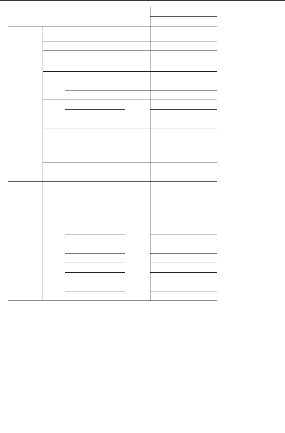
[ VIII Test Run Mode ]
- 188 -
HWE09080 GB
Item
Heat source unit model
PQHY-P120YHMU-A
Operating
conditions
Indoor temperature DB/WB 26.7°C/19.4°C
[80°F/67°F]
Heat source water temperature °C [ °F] 29.4[85]
Heat source water flow rate
m3/h
[G/h]
[gpm]
5.76
[1522]
[25.4]
Indoor
unit
No. of connected units
Unit
3
No. of units in operation 3
Model - 36/36/48
Pipe
length
Main pipe
m [ft]
5 [16-3/8 ]
Branch pipe 10 [32-3/4 ]
Total pipe length 35 [115]
Fan speed - Hi
Refrigerant charge kg
[lbs-oz] 13.6 [30]
Heat source
unit
Current A 23.8
Voltage V 230
Compressor frequency Hz 114
LEV opening
Indoor unit
Pulse
325/325/387
SC (LEV1) 100
LEV2 1400
Pressure
switch
High pressure (after O/S)/
Low pressure (before accumulator)
MPa
[psi] 2.30/0.81 [334/117]
Sectional
temperatures
Heat
source
unit
Discharge (TH4)
°C [°F]
65 [149]
Heat exchanger outlet 35 [95]
Accumulator inlet 8 [46]
Accumulator outlet 8 [46]
Compressor inlet 19 [66]
Compressor shell bottom 42 [108]
Indoor
unit
LEV inlet 19 [66]
Heat exchanger outlet 6 [43]
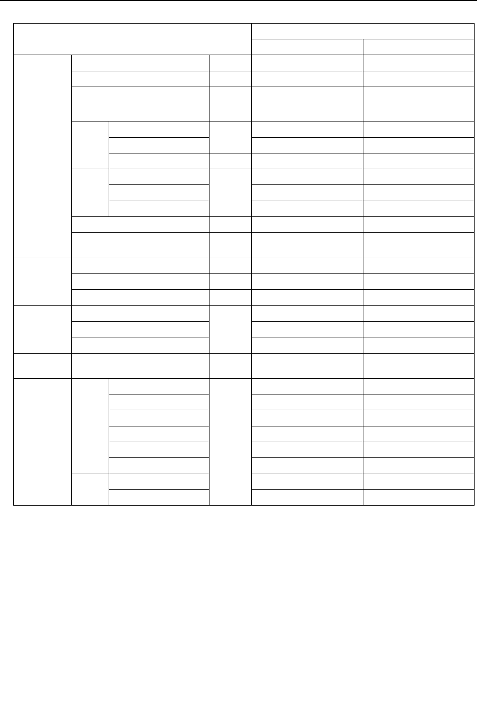
[ VIII Test Run Mode ]
- 189 -
HWE09080 GB
(2) Heating operation
Item
Heat source unit model
PQHY-P72YHMU-A PQHY-P96YHMU-A
Operating
conditions
Indoor temperature DB/WB 21.1°C/- [70°F/-] 21.1°C/- [70°F/-]
Heat source water temperature °C [ °F] 21.1[70] 21.1[70]
Heat source water flow rate
m3/h
[G/h]
[gpm]
5.76
[1522]
[25.4]
5.76
[1522]
[25.4]
Indoor
unit
No. of connected units
Unit
22
No. of units in operation 2 2
Model - 36/36 48/48
Pipe
length
Main pipe
m [ft]
5 [16-3/8 ] 5 [16-3/8 ]
Branch pipe 10 [32-3/4 ] 10 [32-3/4 ]
Total pipe length 25 [82] 25 [82]
Fan speed - Hi Hi
Refrigerant charge kg
[lbs-oz] 11.8 [27] 13.0 [29]
Heat source
unit
Current A 18.6 25.2
Voltage V 230 230
Compressor frequency Hz 60 72
LEV opening
Indoor unit
Pulse
332/332 406/406
SC (LEV1) 0 0
LEV2 1400 1400
Pressure
switch
High pressure (after O/S)/
Low pressure (before accumulator)
MPa
[psi] 2.64/0.80 [383/116] 2.90/0.80 [421/116]
Sectional
temperatures
Heat
source
unit
Discharge (TH4)
°C [°F]
73 [163] 80 [176]
Heat exchanger outlet 5 [41] 5 [41]
Accumulator inlet 4 [39] 4 [39]
Accumulator outlet 4 [39] 4 [39]
Compressor inlet 4 [39] 4 [39]
Compressor shell bottom 40 [104] 40 [104]
Indoor
unit
LEV inlet 37 [99] 38 [100]
Heat exchanger inlet 70 [158] 70 [158]
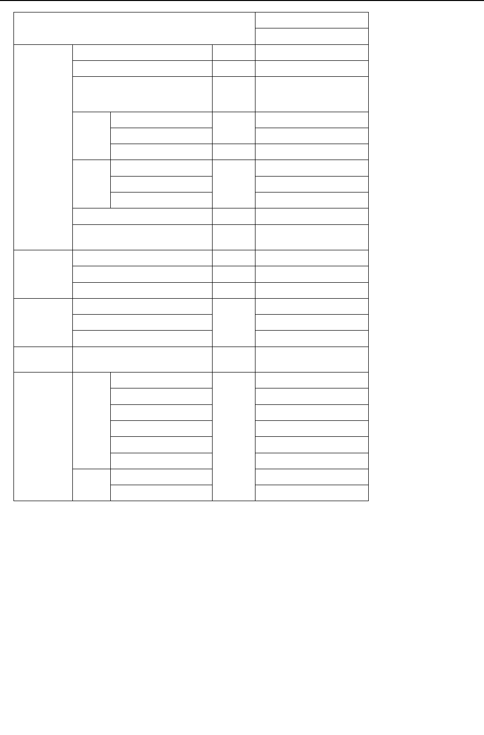
[ VIII Test Run Mode ]
- 190 -
HWE09080 GB
Item
Heat source unit model
PQHY-P120YHMU-A
Operating
conditions
Indoor temperature DB/WB 21.1°C/- [70°F/-]
Heat source water temperature °C [ °F] 21.1[70]
Heat source water flow rate
m3/h
[G/h]
[gpm]
5.76
[1522]
[25.4]
Indoor
unit
No. of connected units
Unit
3
No. of units in operation 3
Model - 36/36/48
Pipe
length
Main pipe
m [ft]
5 [16-3/8 ]
Branch pipe 10 [32-3/4 ]
Total pipe length 35 [115]
Fan speed - Hi
Refrigerant charge kg
[lbs-oz] 13.6 [30]
Heat source
unit
Current A 28.3
Voltage V 230
Compressor frequency Hz 90
LEV opening
Indoor unit
Pulse
332/332/406
SC (LEV1) 0
LEV2 1400
Pressure
switch
High pressure (after O/S)/
Low pressure (before accumulator)
MPa
[psi] 2.68/0.80 [389/116]
Sectional
temperatures
Heat
source
unit
Discharge (TH4)
°C [°F]
81 [178]
Heat exchanger outlet 5 [41]
Accumulator inlet 4 [39]
Accumulator outlet 4 [39]
Compressor inlet 4 [39]
Compressor shell bottom 40 [104]
Indoor
unit
LEV inlet 39 [102]
Heat exchanger inlet 70 [158]
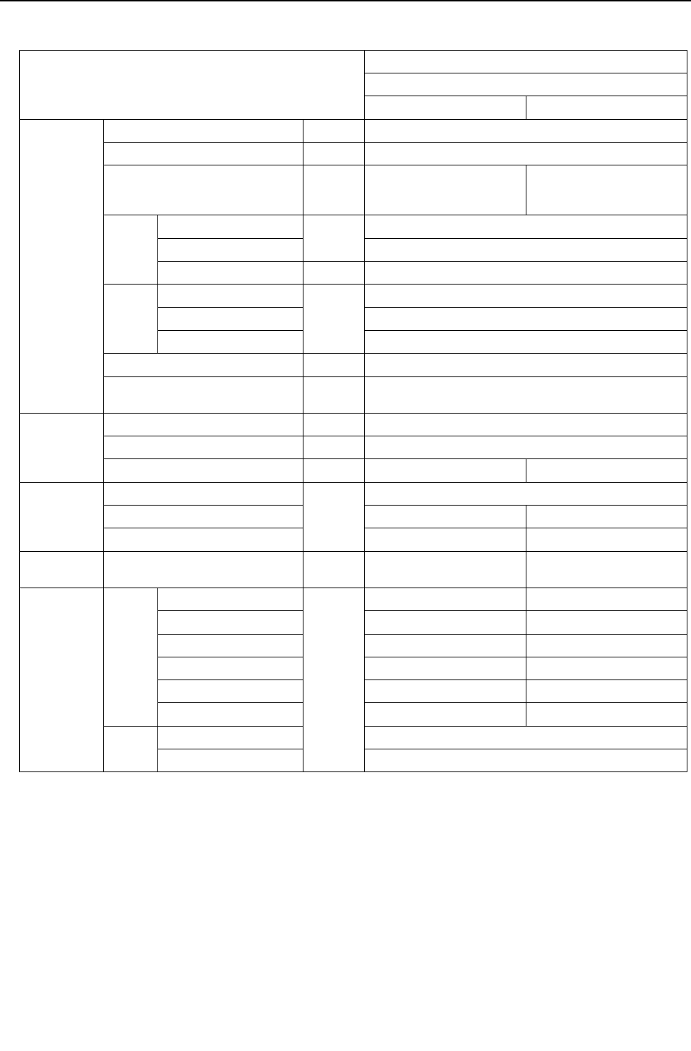
[ VIII Test Run Mode ]
- 191 -
HWE09080 GB
2. 2-unit combination<PQHY>
(1) Cooling operation
Item
2-unit combination
PQHY-P144YSHMU-A
PQHY-P72YHMU-A PQHY-P72YHMU-A
Operating
conditions
Indoor temperature DB/WB 26.7°C/19.4°C[80°F/67°F]
Heat source water temperature °C [ °F] 29.4[85]
Heat source water flow rate
m3/h
G/h
gpm
5.76
[1522]
[25.4]
5.76
[1522]
[25.4]
Indoor
unit
No. of connected units
Unit
4
No. of units in operation 4
Model - 36/36/36/36
Pipe
length
Main pipe
m [ft]
5 [16-3/8]
Branch pipe 10 [32-3/4]
Total pipe length 45 [148]
Fan speed - Hi
Refrigerant charge kg
[lbs-oz] 20.3 [45]
Heat source
unit
Current A 42.3
Voltage V 230
Compressor frequency Hz 66 66
LEV opening
Indoor unit
Pulse
325/325/325/325
SC (LEV1) 80 80
LEV2 1400 1400
Pressure
switch
High pressure (after O/S)/
Low pressure (before accumulator)
MPa
[psi] 2.20/0.81 [319/117] 2.20/0.81 [319/117]
Sectional
temperatures
Heat
source
unit
Discharge (TH4)
°C [°F]
65 [149] 65 [149]
Heat exchanger outlet 33 [91] 33 [91]
Accumulator inlet 8 [46] 8 [46]
Accumulator outlet 8 [46] 8 [46]
Compressor inlet 19 [66] 19 [66]
Compressor shell bottom 47 [117] 47 [117]
Indoor
unit
LEV inlet 19 [66]
Heat exchanger outlet 6 [43]

[ VIII Test Run Mode ]
- 192 -
HWE09080 GB
Item
2-unit combination
PQHY-P168YSHMU-A
PQHY-P96YHMU-A PQHY-P72YHMU-A
Operating
conditions
Indoor temperature DB/WB 26.7°C/19.4°C[80°F/67°F]
Heat source water temperature °C [ °F] 29.4[85]
Heat source water flow rate
m3/h
G/h
gpm
5.76
[1522]
[25.4]
5.76
[1522]
[25.4]
Indoor
unit
No. of connected units
Unit
4
No. of units in operation 4
Model - 36/36/48/48
Pipe
length
Main pipe
m [ft]
5 [16-3/8]
Branch pipe 10 [32-3/4]
Total pipe length 45 [148]
Fan speed - Hi
Refrigerant charge kg
[lbs-oz] 23.1 [51]
Heat source
unit
Current A 42.3
Voltage V 230
Compressor frequency Hz 78 78
LEV opening
Indoor unit
Pulse
325/325/387/387
SC (LEV1) 90 90
LEV2 1400 1400
Pressure
switch
High pressure (after O/S)/
Low pressure (before accumulator)
MPa
[psi] 2.23/0.81 [323/117] 2.23/0.81 [323/117]
Sectional
temperatures
Heat
source
unit
Discharge (TH4)
°C [°F]
65 [149] 65 [149]
Heat exchanger outlet 33 [91] 33 [91]
Accumulator inlet 8 [46] 8 [46]
Accumulator outlet 8 [46] 8 [46]
Compressor inlet 19 [66] 19 [66]
Compressor shell bottom 40 [104] 47 [117]
Indoor
unit
LEV inlet 19 [66]
Heat exchanger outlet 6 [43]

[ VIII Test Run Mode ]
- 193 -
HWE09080 GB
Item
2-unit combination
PQHY-P192YSHMU-A
PQHY-P96YHMU-A PQHY-P96YHMU-A
Operating
conditions
Indoor temperature DB/WB 26.7°C/19.4°C[80°F/67°F]
Heat source water temperature °C [ °F] 29.4[85]
Heat source water flow rate
m3/h
G/h
gpm
5.76
[1522]
[25.4]
5.76
[1522]
[25.4]
Indoor
unit
No. of connected units
Unit
4
No. of units in operation 4
Model - 48/48/48/48
Pipe
length
Main pipe
m [ft]
5 [16-3/8]
Branch pipe 10 [32-3/4]
Total pipe length 45 [148]
Fan speed - Hi
Refrigerant charge kg
[lbs-oz] 24.6 [54]
Heat source
unit
Current A 51.8
Voltage V 230
Compressor frequency Hz 90 90
LEV opening
Indoor unit
Pulse
387/387/387/387
SC (LEV1) 100 100
LEV2 1400 1400
Pressure
switch
High pressure (after O/S)/
Low pressure (before accumulator)
MPa
[psi] 2.27/0.81 [329/117] 2.27/0.81 [329/117]
Sectional
temperatures
Heat
source
unit
Discharge (TH4)
°C [°F]
65 [149] 65 [149]
Heat exchanger outlet 34 [93] 34 [93]
Accumulator inlet 8 [46] 8 [46]
Accumulator outlet 8 [46] 8 [46]
Compressor inlet 19 [66] 19 [66]
Compressor shell bottom 40 [104] 40 [104]
Indoor
unit
LEV inlet 19 [66]
Heat exchanger outlet 6 [43]
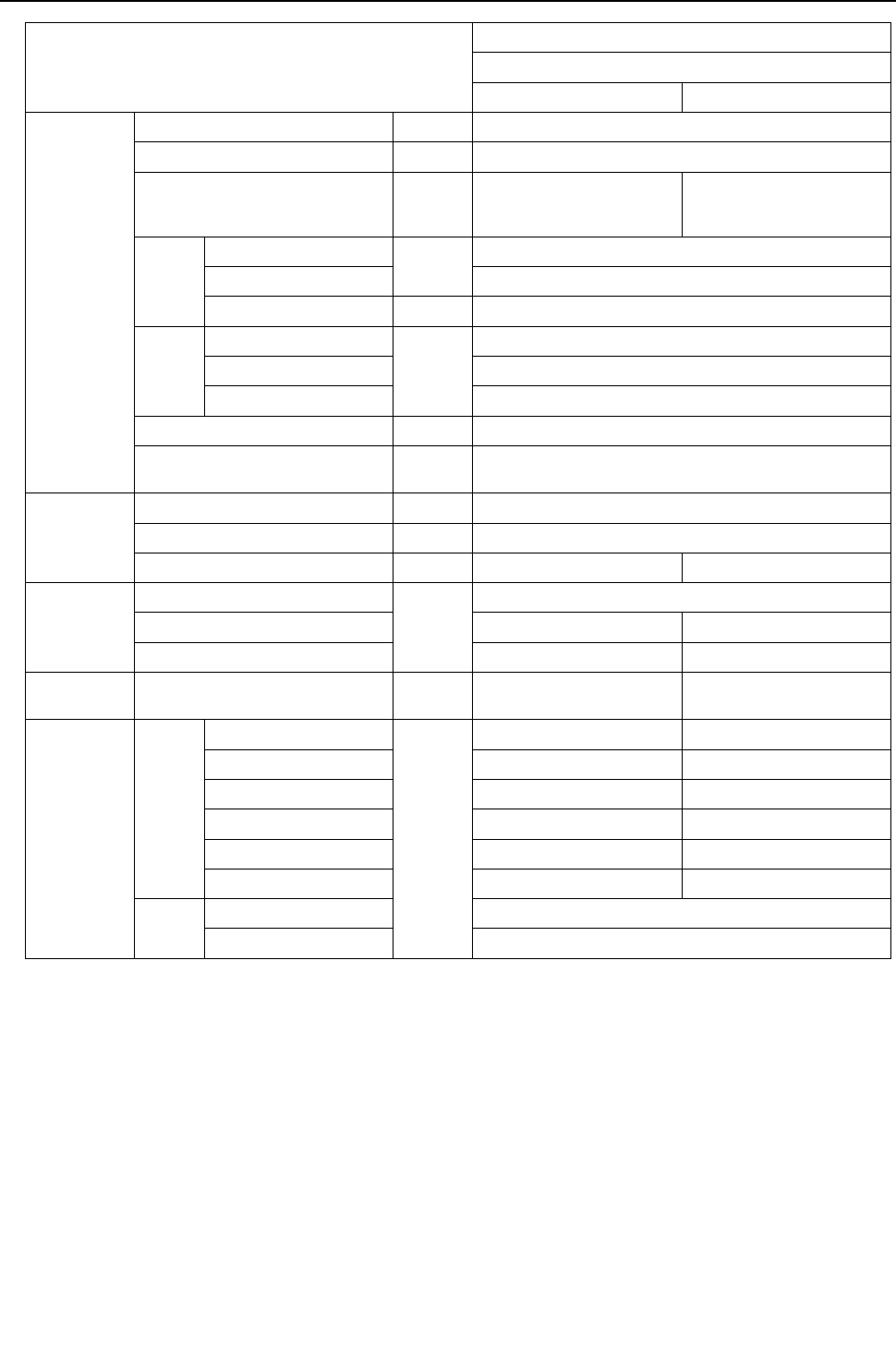
[ VIII Test Run Mode ]
- 194 -
HWE09080 GB
Item
2-unit combination
PQHY-P216YSHMU-A
PQHY-P120YHMU-A PQHY-P96YHMU-A
Operating
conditions
Indoor temperature DB/WB 26.7°C/19.4°C[80°F/67°F]
Heat source water temperature °C [ °F] 29.4[85]
Heat source water flow rate
m3/h
G/h
gpm
5.76
[1522]
[25.4]
5.76
[1522]
[25.4]
Indoor
unit
No. of connected units
Unit
5
No. of units in operation 5
Model - 36/36/48/48/48
Pipe
length
Main pipe
m [ft]
5 [16-3/8]
Branch pipe 10 [32-3/4]
Total pipe length 65 [213]
Fan speed - Hi
Refrigerant charge kg
[lbs-oz] 26.2 [58]
Heat source
unit
Current A 52.2
Voltage V 230
Compressor frequency Hz 98 98
LEV opening
Indoor unit
Pulse
325/325/387/387/387
SC (LEV1) 159 159
LEV2 1400 1400
Pressure
switch
High pressure (after O/S)/
Low pressure (before accumulator)
MPa
[psi] 2.28/0.81 [331/117] 2.28/0.81 [331/117]
Sectional
temperatures
Heat
source
unit
Discharge (TH4)
°C [°F]
65 [149] 65 [149]
Heat exchanger outlet 35 [95] 35 [95]
Accumulator inlet 8 [46] 8 [46]
Accumulator outlet 8 [46] 8 [46]
Compressor inlet 19 [66] 19 [66]
Compressor shell bottom 42 [108] 40 [104]
Indoor
unit
LEV inlet 19 [66]
Heat exchanger outlet 6 [43]

[ VIII Test Run Mode ]
- 195 -
HWE09080 GB
Item
2-unit combination
PQHY-P240YSHMU-A
PQHY-P120YHMU-A PQHY-P120YHMU-A
Operating
conditions
Indoor temperature DB/WB 26.7°C/19.4°C[80°F/67°F]
Heat source water temperature °C [ °F] 29.4[85]
Heat source water flow rate
m3/h
G/h
gpm
5.76
[1522]
[25.4]
5.76
[1522]
[25.4]
Indoor
unit
No. of connected units
Unit
6
No. of units in operation 6
Model - 36/36/36/36/48/48
Pipe
length
Main pipe
m [ft]
5 [16-3/8]
Branch pipe 10 [32-3/4]
Total pipe length 65 [213]
Fan speed - Hi
Refrigerant charge kg
[lbs-oz] 26.2 [58]
Heat source
unit
Current A 32.7
Voltage V 230
Compressor frequency Hz 105 105
LEV opening
Indoor unit
Pulse
325/325/325/325/387/387
SC (LEV1) 159 159
LEV2 1400 1400
Pressure
switch
High pressure (after O/S)/
Low pressure (before accumulator)
MPa
[psi] 2.30/0.81 [334/117] 2.30/0.81 [334/117]
Sectional
temperatures
Heat
source
unit
Discharge (TH4)
°C [°F]
65 [149] 65 [149]
Heat exchanger outlet 35 [95] 35 [95]
Accumulator inlet 8 [46] 8 [46]
Accumulator outlet 8 [46] 8 [46]
Compressor inlet 19 [66] 19 [66]
Compressor shell bottom 42 [108] 40 [104]
Indoor
unit
LEV inlet 19 [66]
Heat exchanger outlet 6 [43]
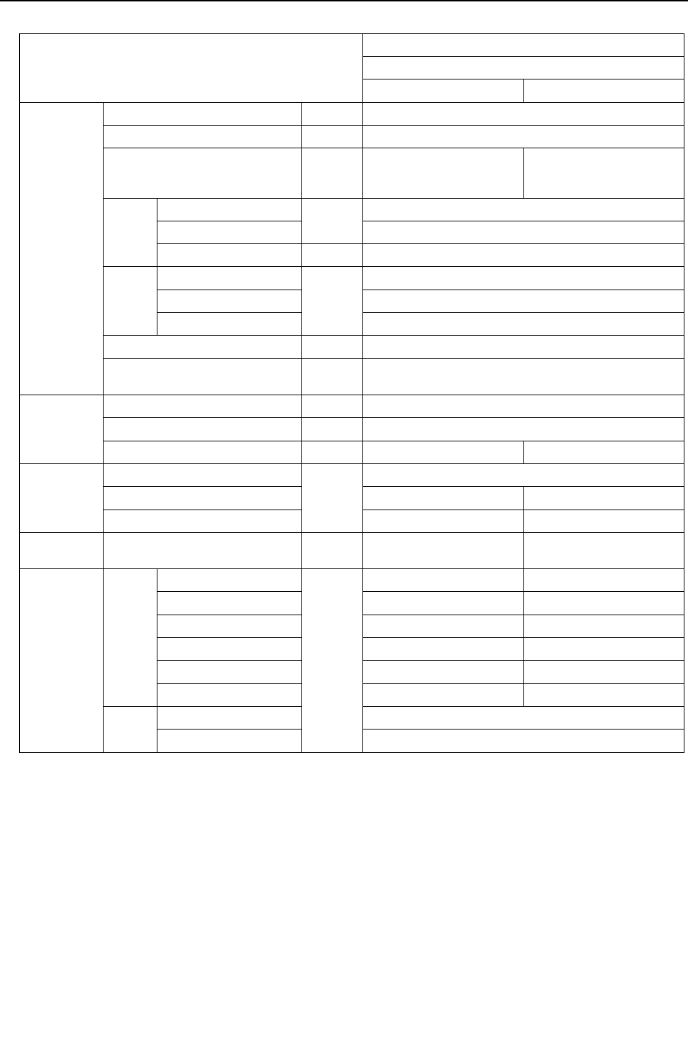
[ VIII Test Run Mode ]
- 196 -
HWE09080 GB
(2) Heating operation
Item
2-unit combination
PQHY-P144YSHMU-A
PQHY-P72YHMU-A PQHY-P72YHMU-A
Operating
conditions
Indoor temperature DB/WB 21.1°C/-[70°F/-]
Heat source water temperature °C [ °F] 21.1[70]
Heat source water flow rate
m3/h
G/h
gpm
5.76
[1522]
[25.4]
5.76
[1522]
[25.4]
Indoor
unit
No. of connected units
Unit
4
No. of units in operation 4
Model - 36/36/36/36
pipe
length
Main pipe
m [ft]
5 [16-3/8]
Branch pipe 10 [32-3/4]
Total pipe length 45 [148]
Fan speed - Hi
Refrigerant charge kg
[lbs-oz] 20.3 [45]
Heat source
unit
Current A 25.5
Voltage V 230
Compressor frequency Hz 60 60
LEV opening
Indoor unit
Pulse
332/332/332/332
SC (LEV1) 0 0
LEV2 1400 1400
Pressure
switch
High pressure (after O/S)/
Low pressure (before accumulator)
MPa
[psi] 2.64/0.80 [383/116] 2.64/0.80 [383/116]
Sectional
temperatures
Heat
source
unit
Discharge (TH4)
°C [°F]
77 [171] 77 [171]
Heat exchanger outlet 5 [41] 5 [41]
Accumulator inlet 4 [39] 4 [39]
Accumulator outlet 4 [39] 4 [39]
Compressor inlet 4 [39] 4 [39]
Compressor shell bottom 40 [104] 40 [104]
Indoor
unit
LEV inlet 37 [99]
Heat exchanger inlet 70 [158]

[ VIII Test Run Mode ]
- 197 -
HWE09080 GB
Item
2-unit combination
PQHY-P168YSHMU-A
PQHY-P96YHMU-A PQHY-P72YHMU-A
Operating
conditions
Indoor temperature DB/WB 21.1°C/-[70°F/-]
Heat source water temperature °C [ °F] 21.1[70]
Heat source water flow rate
m3/h
G/h
gpm
5.76
[1522]
[25.4]
5.76
[1522]
[25.4]
Indoor
unit
No. of connected units
Unit
4
No. of units in operation 4
Model - 36/36/48/48
pipe
length
Main pipe
m [ft]
5 [16-3/8]
Branch pipe 10 [32-3/4]
Total pipe length 45 [148]
Fan speed - Hi
Refrigerant charge kg
[lbs-oz] 23.1 [51]
Heat source
unit
Current A 44.3
Voltage V 230
Compressor frequency Hz 66 66
LEV opening
Indoor unit
Pulse
332/332/406/406
SC (LEV1) 0 0
LEV2 1400 1400
Pressure
switch
High pressure (after O/S)/
Low pressure (before accumulator)
MPa
[psi] 2.80/0.80 [406/116] 2.80/0.80 [406/116]
Sectional
temperatures
Heat
source
unit
Discharge (TH4)
°C [°F]
77 [171] 77 [171]
Heat exchanger outlet 5 [41] 5 [41]
Accumulator inlet 4 [39] 4 [39]
Accumulator outlet 4 [39] 4 [39]
Compressor inlet 4 [39] 4 [39]
Compressor shell bottom 40 [104] 40 [104]
Indoor
unit
LEV inlet 37 [99]
Heat exchanger inlet 70 [158]

[ VIII Test Run Mode ]
- 198 -
HWE09080 GB
Item
2-unit combination
PQHY-P192YSHMU-A
PQHY-P96YHMU-A PQHY-P96YHMU-A
Operating
conditions
Indoor temperature DB/WB 21.1°C/-[70°F/-]
Heat source water temperature °C [ °F] 21.1[70]
Heat source water flow rate
m3/h
G/h
gpm
5.76
[1522]
[25.4]
5.76
[1522]
[25.4]
Indoor
unit
No. of connected units
Unit
4
No. of units in operation 4
Model - 48/48/48/48
pipe
length
Main pipe
m [ft]
5 [16-3/8]
Branch pipe 10 [32-3/4]
Total pipe length 45 [148]
Fan speed - Hi
Refrigerant charge kg
[lbs-oz] 24.6 [55]
Heat source
unit
Current A 51.1
Voltage V 230
Compressor frequency Hz 72 72
LEV opening
Indoor unit
Pulse
406/406/406/406
SC (LEV1) 0 0
LEV2 1400 1400
Pressure
switch
High pressure (after O/S)/
Low pressure (before accumulator)
MPa
[psi] 2.90/0.80 [421/116] 2.90/0.80 [421/116]
Sectional
temperatures
Heat
source
unit
Discharge (TH4)
°C [°F]
80 [176] 80 [176]
Heat exchanger outlet 5 [41] 5 [41]
Accumulator inlet 4 [39] 4 [39]
Accumulator outlet 4 [39] 4 [39]
Compressor inlet 4 [39] 4 [39]
Compressor shell bottom 40 [104] 40 [104]
Indoor
unit
LEV inlet 37 [99]
Heat exchanger inlet 70 [158]

[ VIII Test Run Mode ]
- 199 -
HWE09080 GB
Item
2-unit combination
PQHY-P216YSHMU-A
PQHY-P120YHMU-A PQHY-P96YHMU-A
Operating
conditions
Indoor temperature DB/WB 21.1°C/-[70°F/-]
Heat source water temperature °C [ °F] 21.1[70]
Heat source water flow rate
m3/h
G/h
gpm
5.76
[1522]
[25.4]
5.76
[1522]
[25.4]
Indoor
unit
No. of connected units
Unit
5
No. of units in operation 5
Model - 36/36/48/48/48
pipe
length
Main pipe
m [ft]
5 [16-3/8]
Branch pipe 10 [32-3/4]
Total pipe length 65 [213]
Fan speed - Hi
Refrigerant charge kg
[lbs-oz] 26.2 [58]
Heat source
unit
Current A 55.1
Voltage V 230
Compressor frequency Hz 81 81
LEV opening
Indoor unit
Pulse
332/332/406/406/406
SC (LEV1) 0 0
LEV2 1400 1400
Pressure
switch
High pressure (after O/S)/
Low pressure (before accumulator)
MPa
[psi] 2.75/0.80 [399/116] 2.75/0.80 [399/116]
Sectional
temperatures
Heat
source
unit
Discharge (TH4)
°C [°F]
81 [178] 81 [178]
Heat exchanger outlet 5 [41] 5 [41]
Accumulator inlet 4 [39] 4 [39]
Accumulator outlet 4 [39] 4 [39]
Compressor inlet 4 [39] 4 [39]
Compressor shell bottom 40 [104] 40 [104]
Indoor
unit
LEV inlet 35 [95]
Heat exchanger inlet 70 [158]

[ VIII Test Run Mode ]
- 200 -
HWE09080 GB
Item
2-unit combination
PQHY-P240YSHMU-A
PQHY-P120YHMU-A PQHY-P120YHMU-A
Operating
conditions
Indoor temperature DB/WB 21.1°C/-[70°F/-]
Heat source water temperature °C [ °F] 21.1[70]
Heat source water flow rate
m3/h
G/h
gpm
5.76
[1522]
[25.4]
5.76
[1522]
[25.4]
Indoor
unit
No. of connected units
Unit
6
No. of units in operation 6
Model - 36/36/36/36/48/48
pipe
length
Main pipe
m [ft]
5 [16-3/8]
Branch pipe 10 [32-3/4]
Total pipe length 65 [213]
Fan speed - Hi
Refrigerant charge kg
[lbs-oz] 26.2 [58]
Heat source
unit
Current A 33.5
Voltage V 230
Compressor frequency Hz 90 90
LEV opening
Indoor unit
Pulse
332/332/332/332/406/406
SC (LEV1) 0 0
LEV2 1400 1400
Pressure
switch
High pressure (after O/S)/
Low pressure (before accumulator)
MPa
[psi] 2.68/0.80 [389/116] 2.68/0.80 [389/116]
Sectional
temperatures
Heat
source
unit
Discharge (TH4)
°C [°F]
81 [178] 81 [178]
Heat exchanger outlet 5 [41] 5 [41]
Accumulator inlet 4 [39] 4 [39]
Accumulator outlet 4 [39] 4 [39]
Compressor inlet 4 [39] 4 [39]
Compressor shell bottom 40 [104] 40 [104]
Indoor
unit
LEV inlet 35 [95]
Heat exchanger inlet 70 [158]

[ VIII Test Run Mode ]
- 201 -
HWE09080 GB
3. 3-unit combination<PQHY>
(1) Cooling operation
Item
3-unit combination
PQHY-P264YSHMU-A
PQHY-
P96YHMU-A
PQHY-
P96YHMU-A
PQHY-
P72YHMU-A
Operating
conditions
Indoor temperature DB/WB 26.7°C/19.4°C [80°F/67°F]
Heat source water temperature °C [°F] 29.4 [85]
Heat source water flow rate
m3/h
G/h
gpm
5.76
[1522]
[25.4]
5.76
[1522]
[25.4]
5.76
[1522]
[25.4]
Indoor
unit
No. of connected units
Unit
6
No. of units in opera-
tion 6
Model - 48/48/48/48/36/36
Pipe
length
Main pipe
m [ft]
5[16-3/8]
Branch pipe 10 [ 32-3/4 ]
Total pipe length 65 [213-1/4]
Fan speed - Hi
Refrigerant charge kg
[lbs-oz] 23.5 [52]
Heat source
unit
Current A 62.6
Voltage V 230
Compressor frequency Hz 82 82 82
LEV opening
Indoor unit
Pulse
387/387/387/387/325/325
SC (LEV1) 130 141 138
LEV2 1400 1400 1400
Pressure
switch
High pressure (after O/S)/
Low pressure (before accumu-
lator)
MPa
[psi]
2.25/0.81 2.25/0.81 2.25/0.81
[326/117] [326/117] [326/117]
Sectional
temperatures
Heat
source
unit
Discharge (TH4)
°C [°F]
65 [149] 65 [149] 65 [149]
Heat exchanger outlet 34 [93] 34 [93] 34 [93]
Accumulator inlet 8 [46] 8 [46] 8 [46]
Accumulator outlet 8 [46] 8 [46] 8 [46]
Compressor inlet 19 [67] 19 [67] 19 [67]
Compressor shell bot-
tom 47 [117] 47 [117] 47 [117]
Indoor
unit
LEV inlet 19 [65]
Heat exchanger outlet 6 [42]

[ VIII Test Run Mode ]
- 202 -
HWE09080 GB
Item
3-unit combination
PQHY-P288YSHMU-A
PQHY-
P96YHMU-A
PQHY-
P96YHMU-A
PQHY-
P96YHMU-A
Operating
conditions
Indoor temperature DB/WB 26.7°C/19.4°C [80°F/67°F]
Heat source water temperature °C [°F] 29.4 [85]
Heat source water flow rate
m3/h
G/h
gpm
5.76
[1522]
[25.4]
5.76
[1522]
[25.4]
5.76
[1522]
[25.4]
Indoor
unit
No. of connected units
Unit
6
No. of units in opera-
tion 6
Model - 48/48/48/48/48/48
Pipe
length
Main pipe
m [ft]
5[16-3/8]
Branch pipe 10 [ 32-3/4 ]
Total pipe length 65 [213-1/4]
Fan speed - Hi
Refrigerant charge kg
[lbs-oz] 25.5 [57]
Heat source
unit
Current A 69.9
Voltage V 230
Compressor frequency Hz 90 90 90
LEV opening
Indoor unit
Pulse
387/387/387/387/387/387
SC (LEV1) 141 141 185
LEV2 1400 1400 1400
Pressure
switch
High pressure (after O/S)/
Low pressure (before accumu-
lator)
MPa
[psi]
2.27/0.81 2.27/0.81 2.27/0.81
[329/117] [329/117] [329/117]
Sectional
temperatures
Heat
source
unit
Discharge (TH4)
°C [°F]
65 [149] 65 [149] 65 [149]
Heat exchanger outlet 34 [93] 34 [93] 34 [93]
Accumulator inlet 8 [46] 8 [46] 8 [46]
Accumulator outlet 8 [46] 8 [46] 8 [46]
Compressor inlet 19 [67] 19 [67] 19 [67]
Compressor shell bot-
tom 40 [104] 40 [104] 40 [104]
Indoor
unit
LEV inlet 19 [65]
Heat exchanger outlet 6 [42]

[ VIII Test Run Mode ]
- 203 -
HWE09080 GB
Item
3-unit combination
PQHY-P312YSHMU-A
PQHY-
P120YHMU-A
PQHY-
P96YHMU-A
PQHY-
P96YHMU-A
Operating
conditions
Indoor temperature DB/WB 26.7°C/19.4°C [80°F/67°F]
Heat source water temperature °C [°F] 29.4 [85]
Heat source water flow rate
m3/h
G/h
gpm
5.76
[1522]
[25.4]
5.76
[1522]
[25.4]
5.76
[1522]
[25.4]
Indoor
unit
No. of connected units
Unit
6
No. of units in opera-
tion 6
Model - 54/54/54/54/48/48
Pipe
length
Main pipe
m [ft]
5[16-3/8]
Branch pipe 10 [ 32-3/4 ]
Total pipe length 65 [213-1/4]
Fan speed - Hi
Refrigerant charge kg
[lbs-oz] 25.5 [57]
Heat source
unit
Current A 77.2
Voltage V 230
Compressor frequency Hz 95 95 95
LEV opening
Indoor unit
Pulse
395/395/395/387/387/387
SC (LEV1) 141 141 185
LEV2 1400 1400 1400
Pressure
switch
High pressure (after O/S)/
Low pressure (before accumu-
lator)
MPa
[psi]
2.28/0.81 2.28/0.81 2.28/0.81
[331/117] [331/117] [331/117]
Sectional
temperatures
Heat
source
unit
Discharge (TH4)
°C [°F]
65 [149] 65 [149] 65 [149]
Heat exchanger outlet 34 [93] 34 [93] 34 [93]
Accumulator inlet 8 [46] 8 [46] 8 [46]
Accumulator outlet 8 [46] 8 [46] 8 [46]
Compressor inlet 19 [67] 19 [67] 19 [67]
Compressor shell bot-
tom 40 [104] 40 [104] 40 [104]
Indoor
unit
LEV inlet 19 [65]
Heat exchanger outlet 6 [42]
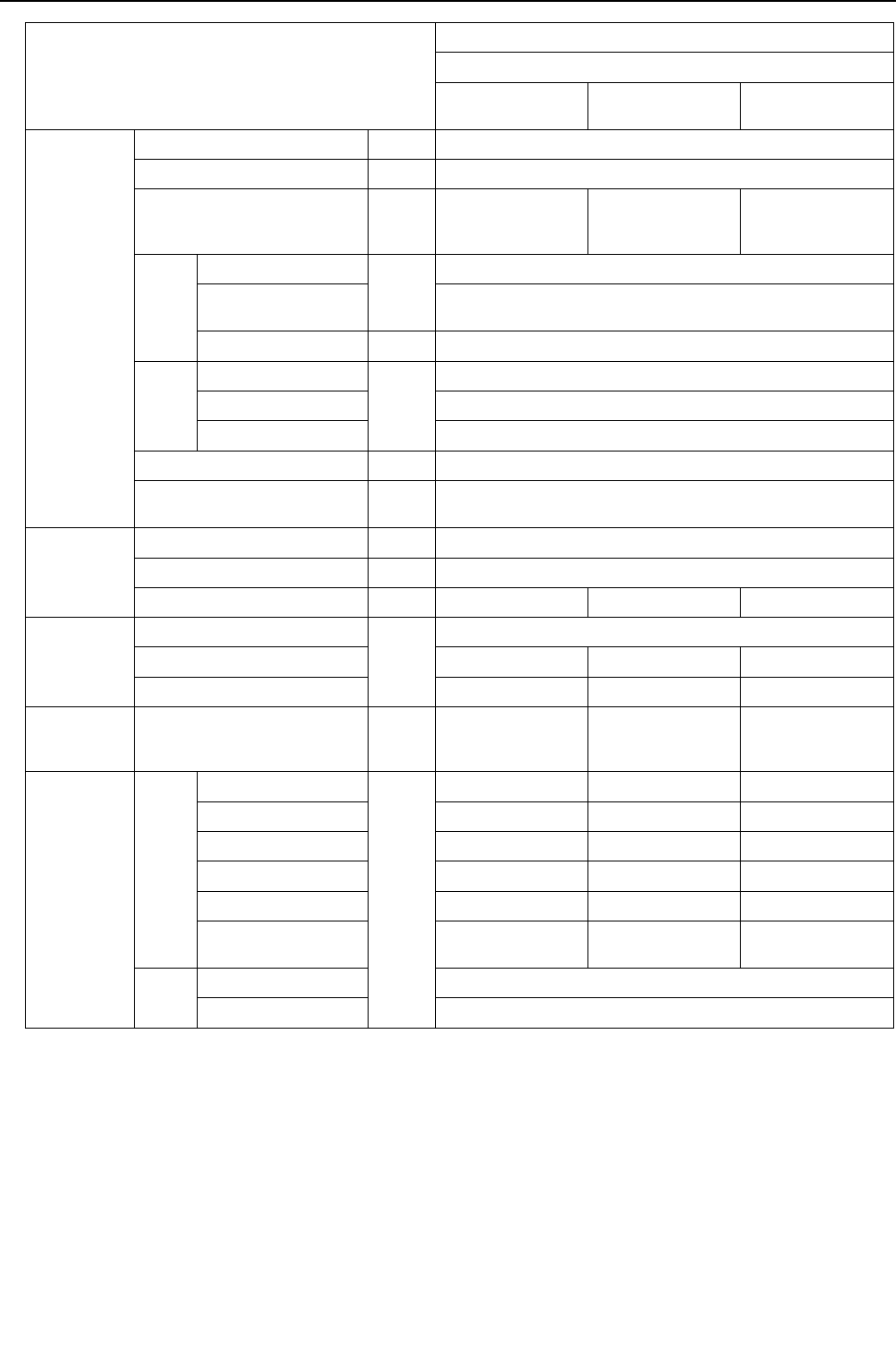
[ VIII Test Run Mode ]
- 204 -
HWE09080 GB
Item
3-unit combination
PQHY-P336YSHMU-A
PQHY-
P120YHMU-A
PQHY-
P120YHMU-A
PQHY-
P96YHMU-A
Operating
conditions
Indoor temperature DB/WB 26.7°C/19.4°C [80°F/67°F]
Heat source water temperature °C [°F] 29.4 [85]
Heat source water flow rate
m3/h
G/h
gpm
5.76
[1522]
[25.4]
5.76
[1522]
[25.4]
5.76
[1522]
[25.4]
Indoor
unit
No. of connected units
Unit
7
No. of units in opera-
tion 7
Model - 48/48/48/48/48/48/48
Pipe
length
Main pipe
m [ft]
5[16-3/8]
Branch pipe 10 [ 32-3/4 ]
Total pipe length 65 [213-1/4]
Fan speed - Hi
Refrigerant charge kg
[lbs-oz] 26.5 [59]
Heat source
unit
Current A 84.2
Voltage V 230
Compressor frequency Hz 100 100 100
LEV opening
Indoor unit
Pulse
387/387/387/387/387/387/387
SC (LEV1) 141 141 185
LEV2 1400 1400 1400
Pressure
switch
High pressure (after O/S)/
Low pressure (before accumu-
lator)
MPa
[psi]
2.29/0.81 2.29/0.81 2.29/0.81
[332/117] [332/117] [332/117]
Sectional
temperatures
Heat
source
unit
Discharge (TH4)
°C [°F]
65 [149] 65 [149] 65 [149]
Heat exchanger outlet 35 [95] 35 [95] 35 [95]
Accumulator inlet 8 [46] 8 [46] 8 [46]
Accumulator outlet 8 [46] 8 [46] 8 [46]
Compressor inlet 19 [67] 19 [67] 19 [67]
Compressor shell bot-
tom 40 [104] 40 [104] 40 [104]
Indoor
unit
LEV inlet 19 [65]
Heat exchanger outlet 6 [42]

[ VIII Test Run Mode ]
- 205 -
HWE09080 GB
Item
3-unit combination
PQHY-P360YSHMU-A
PQHY-
P120YHMU-A
PQHY-
P120YHMU-A
PQHY-
P120YHMU-A
Operating
conditions
Indoor temperature DB/WB 26.7°C/19.4°C [80°F/67°F]
Heat source water temperature °C [°F] 29.4 [85]
Heat source water flow rate
m3/h
G/h
gpm
5.76
[1522]
[25.4]
5.76
[1522]
[25.4]
5.76
[1522]
[25.4]
Indoor
unit
No. of connected units
Unit
7
No. of units in opera-
tion 7
Model - 54/54/54/54/48/48/48
Pipe
length
Main pipe
m [ft]
5[16-3/8]
Branch pipe 10 [ 32-3/4 ]
Total pipe length 75 [246-1/16]
Fan speed - Hi
Refrigerant charge kg
[lbs-oz] 26.8 [60]
Heat source
unit
Current A 89.0
Voltage V 230
Compressor frequency Hz 105 105 105
LEV opening
Indoor unit
Pulse
395/395/395/395/387/387/387
SC (LEV1) 100 100 100
LEV2 1400 1400 1400
Pressure
switch
High pressure (after O/S)/
Low pressure (before accumu-
lator)
MPa
[psi]
2.30/0.81 2.30/0.81 2.30/0.81
[334/117] [334/117] [334/117]
Sectional
temperatures
Heat
source
unit
Discharge (TH4)
°C [°F]
65 [149] 65 [149] 65 [149]
Heat exchanger outlet 35 [95] 35 [95] 35 [95]
Accumulator inlet 8 [46] 8 [46] 8 [46]
Accumulator outlet 8 [46] 8 [46] 8 [46]
Compressor inlet 19 [67] 19 [67] 19 [67]
Compressor shell bot-
tom 42 [105] 42 [105] 42 [105]
Indoor
unit
LEV inlet 19 [65]
Heat exchanger outlet 6 [42]
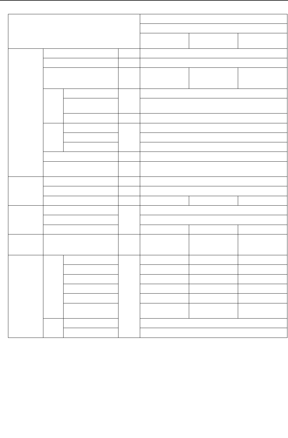
[ VIII Test Run Mode ]
- 206 -
HWE09080 GB
(2) Heating operation
Item
3-unit combination
PQHY-P264YSHMU-A
PQHY-
P96YHMU-A
PQHY-
P96YHMU-A
PQHY-
P72YHMU-A
Operating
conditions
Indoor temperature DB/WB 21.1°C/- [70°F/-]
Heat source water temperature °C [°F] 21.1 [70]
Heat source water flow rate
m3/h
G/h
gpm
5.76
[1522]
[25.4]
5.76
[1522]
[25.4]
5.76
[1522]
[25.4]
Indoor
unit
No. of connected units
Unit
6
No. of units in opera-
tion 6
Model - 48/48/48/48/36/36
Pipe
length
Main pipe
m [ft]
5[16-3/8]
Branch pipe 10 [32-3/4]
Total pipe length 65 [213-1/4]
Fan speed - Hi
Refrigerant charge kg
[lbs-oz] 23.5 [52]
Heat source
unit
Current A 66.1
Voltage V 230
Compressor frequency Hz 70 70 70
LEV opening
Indoor unit
Pulse
406/406/406/406/332/332
SC (LEV1) 0
LEV2 1400 1400 1400
Pressure
switch
High pressure (after O/S)/
Low pressure (before accumu-
lator)
MPa
[psi]
2.81/0.80 2.81/0.80 2.81/0.80
[408/116] [408/116] [408/116]
Sectional
temperatures
Heat
source
unit
Discharge (TH4)
°C [°F]
77 [171] 77 [171] 77 [171]
Heat exchanger outlet 5 [41] 5 [41] 5 [41]
Accumulator inlet 4 [39] 4 [39] 4 [39]
Accumulator outlet 4 [39] 4 [39] 4 [39]
Compressor inlet 4 [39] 4 [39] 4 [39]
Compressor shell bot-
tom 40 [104] 40 [104] 40 [104]
Indoor
unit
LEV inlet 38 [100]
Heat exchanger inlet 70 [158]

[ VIII Test Run Mode ]
- 207 -
HWE09080 GB
Item
3-unit combination
PQHY-P288YSHMU-A
PQHY-
P96YHMU-A
PQHY-
P96YHMU-A
PQHY-
P96YHMU-A
Operating
conditions
Indoor temperature DB/WB 21.1°C/- [70°F/-]
Heat source water temperature °C [°F] 21.1 [70]
Heat source water flow rate
m3/h
G/h
gpm
5.76
[1522]
[25.4]
5.76
[1522]
[25.4]
5.76
[1522]
[25.4]
Indoor
unit
No. of connected units
Unit
6
No. of units in opera-
tion 6
Model - 48/48/48/48/48/48
Pipe
length
Main pipe
m [ft]
5[16-3/8]
Branch pipe 10 [32-3/4]
Total pipe length 65 [213-1/4]
Fan speed - Hi
Refrigerant charge kg
[lbs-oz] 25.5 [57]
Heat source
unit
Current A 71.0
Voltage V 230
Compressor frequency Hz 72 72 72
LEV opening
Indoor unit
Pulse
406/406/406/406/406/406
SC (LEV1) 0
LEV2 1400 1400 1400
Pressure
switch
High pressure (after O/S)/
Low pressure (before accumu-
lator)
MPa
[psi]
2.90/0.80 2.90/0.80 2.90/0.80
[421/116] [421/116] [421/116]
Sectional
temperatures
Heat
source
unit
Discharge (TH4)
°C [°F]
80 [176] 80 [176] 80 [176]
Heat exchanger outlet 5 [41] 5 [41] 5 [41]
Accumulator inlet 4 [39] 4 [39] 4 [39]
Accumulator outlet 4 [39] 4 [39] 4 [39]
Compressor inlet 4 [39] 4 [39] 4 [39]
Compressor shell bot-
tom 40 [104] 40 [104] 40 [104]
Indoor
unit
LEV inlet 39 [102]
Heat exchanger inlet 70 [158]

[ VIII Test Run Mode ]
- 208 -
HWE09080 GB
Item
3-unit combination
PQHY-P312YSHMU-A
PQHY-
P120YHMU-A
PQHY-
P96YHMU-A
PQHY-
P96YHMU-A
Operating
conditions
Indoor temperature DB/WB 21.1°C/- [70°F/-]
Heat source water temperature °C [°F] 21.1 [70]
Heat source water flow rate
m3/h
G/h
gpm
5.76
[1522]
[25.4]
5.76
[1522]
[25.4]
5.76
[1522]
[25.4]
Indoor
unit
No. of connected units
Unit
6
No. of units in opera-
tion 6
Model - 54/54/54/54/48/48
Pipe
length
Main pipe
m [ft]
5[16-3/8]
Branch pipe 10 [32-3/4]
Total pipe length 65 [213-1/4]
Fan speed - Hi
Refrigerant charge kg
[lbs-oz] 25.5 [57]
Heat source
unit
Current A 71.7
Voltage V 230
Compressor frequency Hz 78 78 78
LEV opening
Indoor unit
Pulse
414/414/414/414/406/406
SC (LEV1) 0
LEV2 1400 1400 1400
Pressure
switch
High pressure (after O/S)/
Low pressure (before accumu-
lator)
MPa
[psi]
2.82/0.80 2.82/0.80 2.82/0.80
[409/116] [409/116] [409/116]
Sectional
temperatures
Heat
source
unit
Discharge (TH4)
°C [°F]
80 [176] 80 [176] 80 [176]
Heat exchanger outlet 5 [41] 5 [41] 5 [41]
Accumulator inlet 4 [39] 4 [39] 4 [39]
Accumulator outlet 4 [39] 4 [39] 4 [39]
Compressor inlet 4 [39] 4 [39] 4 [39]
Compressor shell bot-
tom 40 [104] 40 [104] 40 [104]
Indoor
unit
LEV inlet 38 [100]
Heat exchanger inlet 70 [158]

[ VIII Test Run Mode ]
- 209 -
HWE09080 GB
Item
3-unit combination
PQHY-P336YSHMU-A
PQHY-
P120YHMU-A
PQHY-
P120YHMU-A
PQHY-
P96YHMU-A
Operating
conditions
Indoor temperature DB/WB 21.1°C/- [70°F/-]
Heat source water temperature °C [°F] 21.1 [70]
Heat source water flow rate
m3/h
G/h
gpm
5.76
[1522]
[25.4]
5.76
[1522]
[25.4]
5.76
[1522]
[25.4]
Indoor
unit
No. of connected units
Unit
7
No. of units in opera-
tion 7
Model - 48/48/48/48/48/48/48
Pipe
length
Main pipe
m [ft]
5[16-3/8]
Branch pipe 10 [32-3/4]
Total pipe length 65 [213-1/4]
Fan speed - Hi
Refrigerant charge kg
[lbs-oz] 26.5 [59]
Heat source
unit
Current A 79.1
Voltage V 230
Compressor frequency Hz 83 83 83
LEV opening
Indoor unit
Pulse
406/406/406/406/406/406/406
SC (LEV1) 0
LEV2 1400 1400 1400
Pressure
switch
High pressure (after O/S)/
Low pressure (before accumu-
lator)
MPa
[psi]
2.72/0.80 2.72/0.80 2.72/0.80
[395/116] [395/116] [395/116]
Sectional
temperatures
Heat
source
unit
Discharge (TH4)
°C [°F]
81 [178] 81 [178] 81 [178]
Heat exchanger outlet 5 [41] 5 [41] 5 [41]
Accumulator inlet 4 [39] 4 [39] 4 [39]
Accumulator outlet 4 [39] 4 [39] 4 [39]
Compressor inlet 4 [39] 4 [39] 4 [39]
Compressor shell bot-
tom 40 [104] 40 [104] 40 [104]
Indoor
unit
LEV inlet 39 [102]
Heat exchanger inlet 70 [158]

[ VIII Test Run Mode ]
- 210 -
HWE09080 GB
Item
3-unit combination
PQHY-P360YSHMU-A
PQHY-
P120YHMU-A
PQHY-
P120YHMU-A
PQHY-
P120YHMU-A
Operating
conditions
Indoor temperature DB/WB 21.1°C/- [70°F/-]
Heat source water temperature °C [°F] 21.1 [70]
Heat source water flow rate
m3/h
G/h
gpm
5.76
[1522]
[25.4]
5.76
[1522]
[25.4]
5.76
[1522]
[25.4]
Indoor
unit
No. of connected units
Unit
7
No. of units in opera-
tion 7
Model - 54/54/54/54/48/48/48
Pipe
length
Main pipe
m [ft]
5[16-3/8]
Branch pipe 10 [32-3/4]
Total pipe length 75 [246-1/16]
Fan speed - Hi
Refrigerant charge kg
[lbs-oz] 26.8 [60]
Heat source
unit
Current A 84.3
Voltage V 230
Compressor frequency Hz 90 90 90
LEV opening
Indoor unit
Pulse
414/414/414/414/406/406/406
SC (LEV1) 0
LEV2 1400 1400 1400
Pressure
switch
High pressure (after O/S)/
Low pressure (before accumu-
lator)
MPa
[psi]
2.68/0.80 2.68/0.80 2.68/0.80
[389/116] [389/116] [389/116]
Sectional
temperatures
Heat
source
unit
Discharge (TH4)
°C [°F]
81 [178] 81 [178] 81 [178]
Heat exchanger outlet 5 [41] 5 [41] 5 [41]
Accumulator inlet 4 [39] 4 [39] 4 [39]
Accumulator outlet 4 [39] 4 [39] 4 [39]
Compressor inlet 4 [39] 4 [39] 4 [39]
Compressor shell bot-
tom 40 [104] 40 [104] 40 [104]
Indoor
unit
LEV inlet 39 [102]
Heat exchanger inlet 70 [158]
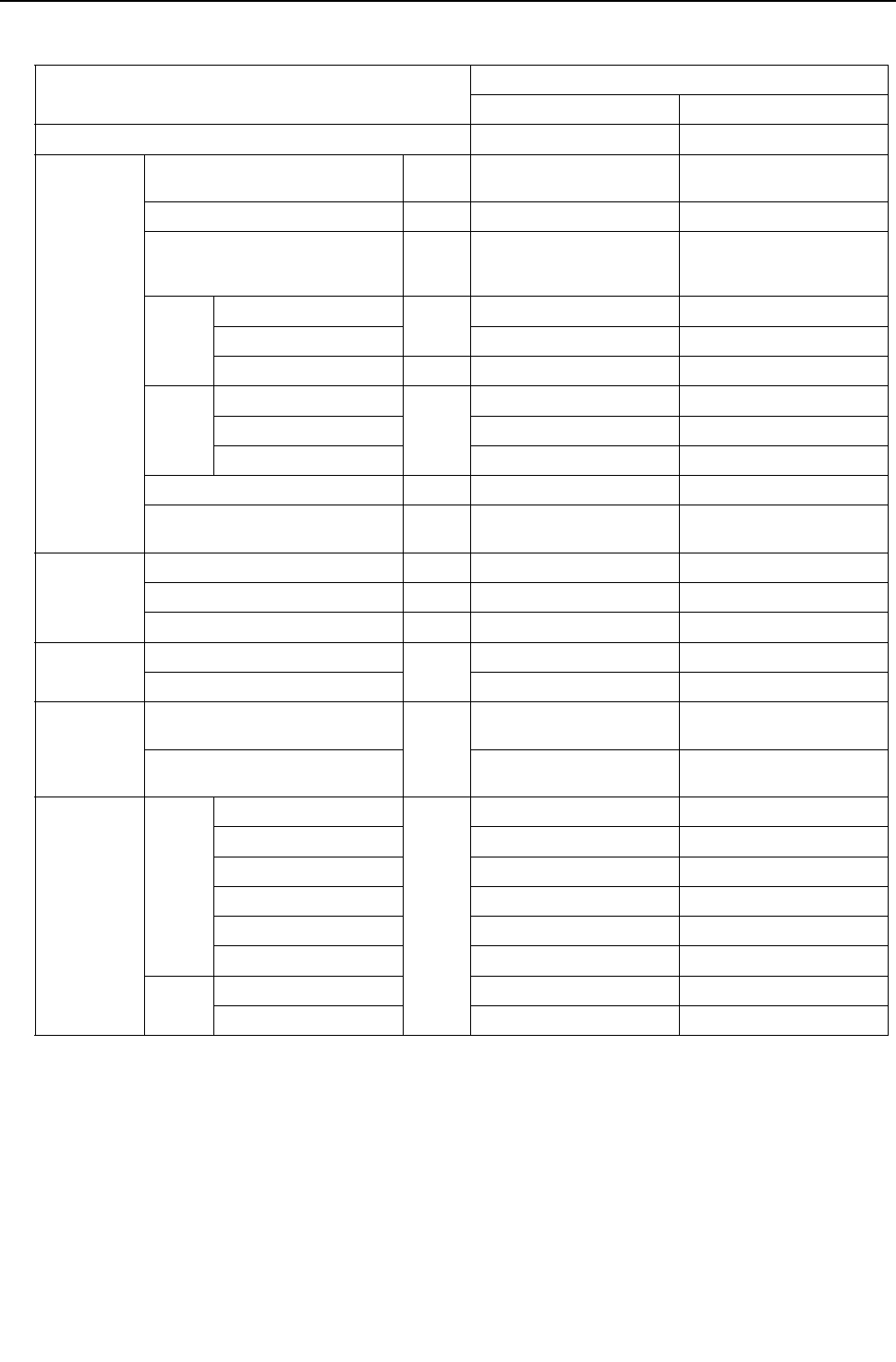
[ VIII Test Run Mode ]
- 211 -
HWE09080 GB
4. Single unit<PQRY>
(1) Cooling only operation
Item
Heat source unit model
PQRY-P72YHMU-A PQRY-P96YHMU-A
Model name of BC controller CMB-P104NU-G CMB-P104NU-G
Operating
conditions
Indoor temperature DB/WB 26.7°C/19.4°C
[80 °F/67 °F]
26.7°C/19.4°C
[80 °F/67 °F]
Heat source water temperature °C [ °F] 29.4[85] 29.4[85]
Heat source water flow rate
m3/h
[G/h]
[gpm]
5.76
[1522]
[25.4]
5.76
[1522]
[25.4]
Indoor
unit
No. of connected units
Unit
22
No. of units in operation 2 2
Model 36/36 48/48
Pipe
length
Main pipe
m [ft]
5 [16-3/8] 5 [16-3/8]
Branch pipe 10 [32-3/4] 10 [32-3/4]
Total pipe length 25 [82] 25 [82]
Fan speed Hi Hi
Refrigerant charge kg
[lbs-oz] 11.8 [27] 13.0 [29]
Heat source
unit
Current A 17.7 23.3
Voltage V 230 230
Compressor frequency Hz 66 90
LEV opening
Indoor unit
Pulse
325/325 387/387
BC controller (1/2/3) 2000//160 2000//170
Pressure
switch
High pressure (63HS1)/
Low pressure (63LS) MPa
[psi]
2.20/0.81
[319/117]
2.27/0.81
[329/117]
BC controller on the liquid side
(PS1)/Intermediate part (PS3)
2.10/2.10
[305/305]
2.17/2.17
[315/315]
Sectional
temperatures
Heat
source
unit
Discharge (TH4)
°C [ °F]
65 [149] 65 [149]
Heat exchanger outlet 33 [91] 34 [93]
Accumulator inlet 8 [46] 8 [46]
Accumulator outlet 8 [46] 8 [46]
Compressor inlet 19 [66] 19 [66]
Compressor shell bottom 47 [117] 40 [104]
Indoor
unit
LEV inlet 19 [66] 19 [66]
Heat exchanger outlet 6 [43] 6 [43]

[ VIII Test Run Mode ]
- 212 -
HWE09080 GB
Item
Heat source unit model
PQRY-P120YHMU-A
Model name of BC controller CMB-P104NU-G
Operating
conditions
Indoor temperature DB/WB 26.7°C/19.4°C
[80 °F/67 °F]
Heat source water temperature °C [ °F] 29.4[85]
Heat source water flow rate
m3/h
[G/h]
[gpm]
5.76
[1522]
[25.4]
Indoor
unit
No. of connected units
Unit
3
No. of units in operation 3
Model 36/36/48
Pipe
length
Main pipe
m [ft]
5 [16-3/8]
Branch pipe 10 [32-3/4]
Total pipe length 35 [115]
Fan speed Hi
Refrigerant charge kg
[lbs-oz] 13.6 [30]
Heat source
unit
Current A 23.8
Voltage V 230
Compressor frequency Hz 105
LEV opening
Indoor unit
Pulse
325/325/387
BC controller (1/2/3) 2000//180
Pressure
switch
High pressure (63HS1)/
Low pressure (63LS) MPa
[psi]
2.30/0.81
[334/117]
BC controller on the liquid side
(PS1)/Intermediate part (PS3)
2.20/2.20
[319/319]
Sectional
temperatures
Heat
source
unit
Discharge (TH4)
°C [ °F]
65 [149]
Heat exchanger outlet 35 [95]
Accumulator inlet 8 [46]
Accumulator outlet 8 [46]
Compressor inlet 19 [66]
Compressor shell bottom 42 [108]
Indoor
unit
LEV inlet 19 [66]
Heat exchanger outlet 6 [43]
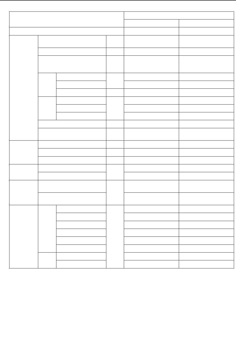
[ VIII Test Run Mode ]
- 213 -
HWE09080 GB
(2) Heating only operation
Item
Heat source unit model
PQRY-P72YHMU-A PQRY-P96YHMU-A
Model name of BC controller CMB-P104NU-G CMB-P104NU-G
Operating
conditions
Indoor temperature DB/WB 21.1°C/
[70 °F/]
21.1°C/
[70 °F/]
Heat source water temperature °C [ °F] 21.1[70] 21.1[70]
Heat source water flow rate
m3/h
[G/h]
[gpm]
5.76
[1522]
[25.4]
5.76
[1522]
[25.4]
Indoor
unit
No. of connected units
Unit
22
No. of units in operation 2 2
Model 36/36 48/48
Pipe
length
Main pipe
m [ft]
5 [16-3/8] 5 [16-3/8]
Branch pipe 10 [32-3/4] 10 [32-3/4]
Total pipe length 25 [82] 25 [82]
Fan speed Hi Hi
Refrigerant charge kg
[lbs-oz] 11.8 [27] 13.0 [29]
Heat source
unit
Current A 18.6 25.2
Voltage V 230 230
Compressor frequency Hz 60 72
LEV opening
Indoor unit
Pulse
332/332 406/406
BC controller (1/2/3) 110//520 110//590
Pressure
switch
High pressure (63HS1)/
Low pressure (63LS) MPa
[psi]
2.64/0.80
[383/116]
2.90/0.80
[421/116]
BC controller on the liquid side
(PS1)/Intermediate part (PS3)
2.61/2.29
[378/332]
2.87/2.55
[416/370]
Sectional
temperatures
Heat
source
unit
Discharge (TH4)
°C [ °F]
73 [163] 80 [176]
Heat exchanger outlet 5 [41] 5 [41]
Accumulator inlet 4 [39] 4 [39]
Accumulator outlet 4 [39] 4 [39]
Compressor inlet 4 [39] 4 [39]
Compressor shell bottom 40 [104] 40 [104]
Indoor
unit
LEV inlet 37 [99] 38 [100]
Heat exchanger inlet 70 [158] 70 [158]
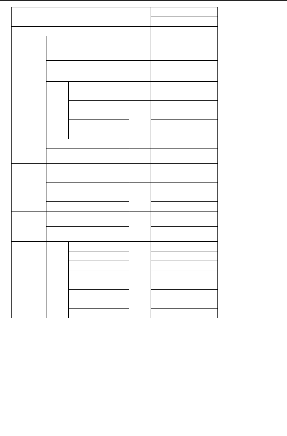
[ VIII Test Run Mode ]
- 214 -
HWE09080 GB
Item
Heat source unit model
PQRY-P120YHMU-A
Model name of BC controller CMB-P104NU-G
Operating
conditions
Indoor temperature DB/WB 21.1°C/
[70 °F/]
Heat source water temperature °C [ °F] 21.1[70]
Heat source water flow rate
m3/h
[G/h]
[gpm]
5.76
[1522]
[25.4]
Indoor
unit
No. of connected units
Unit
3
No. of units in operation 3
Model 36/36/48
Pipe
length
Main pipe
m [ft]
5 [16-3/8]
Branch pipe 10 [32-3/4]
Total pipe length 35 [115]
Fan speed Hi
Refrigerant charge kg
[lbs-oz] 13.6 [30]
Heat source
unit
Current A 28.3
Voltage V 230
Compressor frequency Hz 90
LEV opening
Indoor unit
Pulse
332/332/406
BC controller (1/2/3) 110//660
Pressure
switch
High pressure (63HS1)/
Low pressure (63LS) MPa
[psi]
2.68/0.80
[389/116]
BC controller on the liquid side
(PS1)/Intermediate part (PS3)
2.64/2.32
[383/336]
Sectional
temperatures
Heat
source
unit
Discharge (TH4)
°C [ °F]
81 [178]
Heat exchanger outlet 5 [41]
Accumulator inlet 4 [39]
Accumulator outlet 4 [39]
Compressor inlet 4 [39]
Compressor shell bottom 40 [104]
Indoor
unit
LEV inlet 39 [102]
Heat exchanger inlet 70 [158]
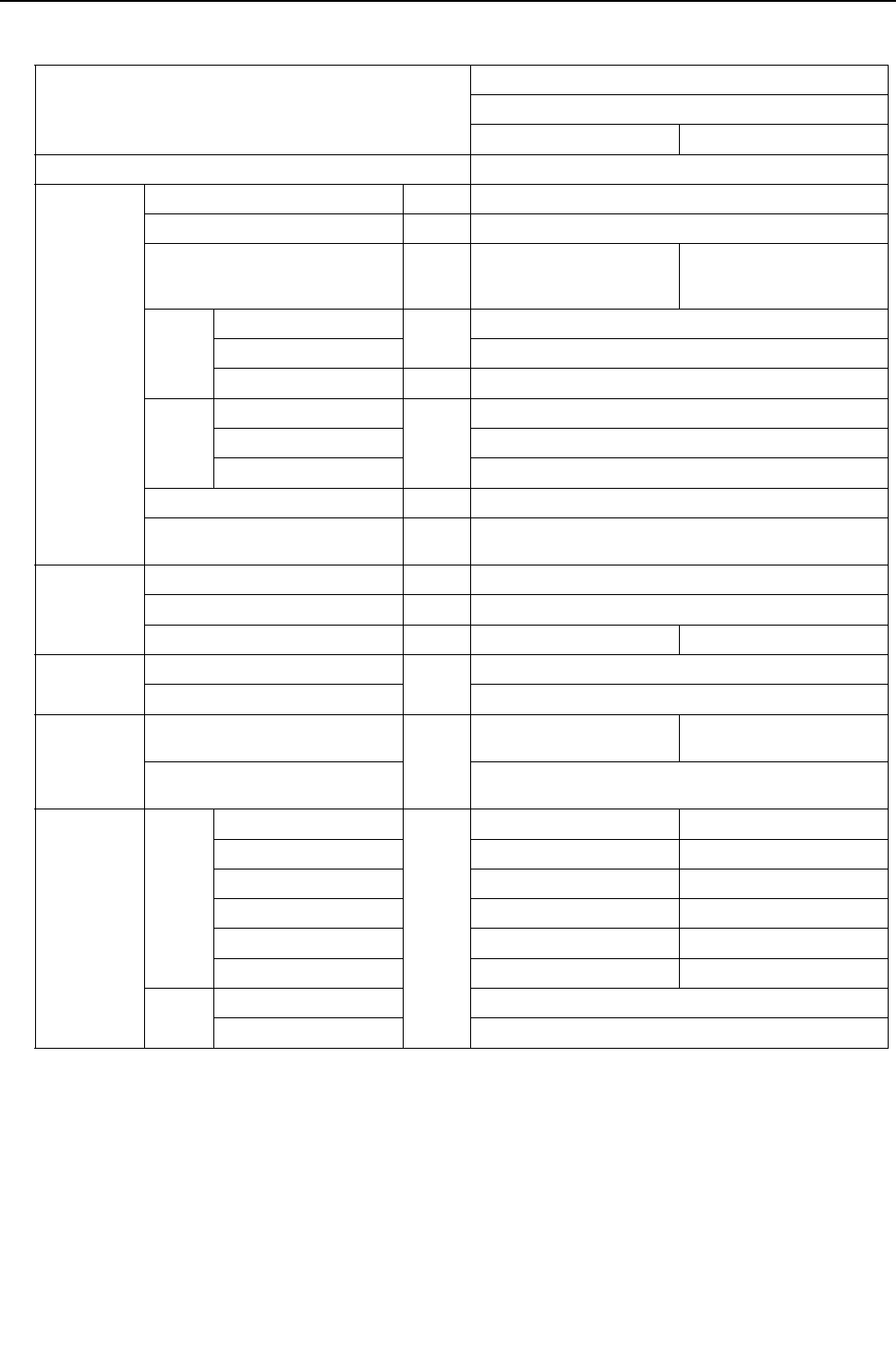
[ VIII Test Run Mode ]
- 215 -
HWE09080 GB
5. 2-unit combination<PQRY>
(1) Cooling only operation
Item
2-unit combination
PQRY-P144YSHMU-A
PQRY-P72YHMU-A PQRY-P72YHMU-A
Model name of BC controller CMB-P108NU-GA
Operating
conditions
Indoor temperature DB/WB 26.7°C/19.4°C [80 °F/67 °F]
Heat source water temperature °C [ °F] 29.4 [85]
Heat source water flow rate
m3/h
G/h
gpm
5.76
[1522]
[25.4]
5.76
[1522]
[25.4]
Indoor
unit
No. of connected units
Unit
4
No. of units in operation 4
Model 36/36/36/36
Pipe
length
Main pipe
m [ft]
5[16-3/8]
Branch pipe 10 [32-3/4]
Total pipe length 45 [148]
Fan speed Hi
Refrigerant charge kg
[lbs-oz] 20.3 [45]
Heat source
unit
Current A 42.3
Voltage V 230
Compressor frequency Hz 66 66
LEV opening
Indoor unit
Pulse
325/325/387/387
BC controller (1/2/3) 2000/2000/210
Pressure
switch
High pressure (63HS1)/
Low pressure (63LS) MPa
[psi]
2.20/0.81
[319/117]
2.20/0.81
[319/117]
BC controller on the liquid side
(PS1)/Intermediate part (PS3)
2.10/2.10
[305/305]
Sectional
temperatures
Heat
source
unit
Discharge (TH4)
°C [ °F]
65 [149] 65 [149]
Heat exchanger outlet 33 [91] 33 [91]
Accumulator inlet 8 [46] 8 [46]
Accumulator outlet 8 [46] 8 [46]
Compressor inlet 19 [66] 19 [66]
Compressor shell bottom 40 [104] 47 [117]
Indoor
unit
LEV inlet 19 [66]
Heat exchanger outlet 6 [43]

[ VIII Test Run Mode ]
- 216 -
HWE09080 GB
Item
2-unit combination
PQRY-P168YSHMU-A
PQRY-P96YHMU-A PQRY-P72YHMU-A
Model name of BC controller CMB-P108NU-GA
Operating
conditions
Indoor temperature DB/WB 26.7°C/19.4°C [80 °F/67 °F]
Heat source water temperature °C [ °F] 29.4 [85]
Heat source water flow rate
m3/h
G/h
gpm
5.76
[1522]
[25.4]
5.76
[1522]
[25.4]
Indoor
unit
No. of connected units
Unit
4
No. of units in operation 4
Model 36/36/48/48
Pipe
length
Main pipe
m [ft]
5[16-3/8]
Branch pipe 10 [32-3/4]
Total pipe length 45 [148]
Fan speed Hi
Refrigerant charge kg
[lbs-oz] 23.1 [51]
Heat source
unit
Current A 42.3
Voltage V 230
Compressor frequency Hz 78 78
LEV opening
Indoor unit
Pulse
325/325/387/387
BC controller (1/2/3) 2000/2000/210
Pressure
switch
High pressure (63HS1)/
Low pressure (63LS) MPa
[psi]
2.23/0.81
[323/117]
2.23/0.81
[323/117]
BC controller on the liquid side
(PS1)/Intermediate part (PS3)
2.13/2.13
[309/309]
Sectional
temperatures
Heat
source
unit
Discharge (TH4)
°C [ °F]
65 [149] 65 [149]
Heat exchanger outlet 33 [91] 33 [91]
Accumulator inlet 8 [46] 8 [46]
Accumulator outlet 8 [46] 8 [46]
Compressor inlet 19 [66] 19 [66]
Compressor shell bottom 40 [104] 47 [117]
Indoor
unit
LEV inlet 19 [66]
Heat exchanger outlet 6 [43]

[ VIII Test Run Mode ]
- 217 -
HWE09080 GB
Item
2-unit combination
PQRY-P192YSHMU-A
PQRY-P96YHMU-A PQRY-P96YHMU-A
Model name of BC controller CMB-P108NU-GA
Operating
conditions
Indoor temperature DB/WB 26.7°C/19.4°C [80 °F/67 °F]
Heat source water temperature °C [ °F] 29.4 [85]
Heat source water flow rate
m3/h
G/h
gpm
5.76
[1522]
[25.4]
5.76
[1522]
[25.4]
Indoor
unit
No. of connected units
Unit
4
No. of units in operation 4
Model 48/48/48/48
Pipe
length
Main pipe
m [ft]
5[16-3/8]
Branch pipe 10 [32-3/4]
Total pipe length 45 [148]
Fan speed Hi
Refrigerant charge kg
[lbs-oz] 24.6 [55]
Heat source
unit
Current A 51.8
Voltage V 230
Compressor frequency Hz 90 90
LEV opening
Indoor unit
Pulse
387/387/387/387
BC controller (1/2/3) 2000/2000/220
Pressure
switch
High pressure (63HS1)/
Low pressure (63LS) MPa
[psi]
2.27/0.81
[329/117]
2.27/0.81
[329/117]
BC controller on the liquid side
(PS1)/Intermediate part (PS3)
2.17/2.17
[315/315]
Sectional
temperatures
Heat
source
unit
Discharge (TH4)
°C [ °F]
65 [149] 65 [149]
Heat exchanger outlet 34 [93] 34 [93]
Accumulator inlet 8 [46] 8 [46]
Accumulator outlet 8 [46] 8 [46]
Compressor inlet 19 [66] 19 [66]
Compressor shell bottom 40 [104] 40 [104]
Indoor
unit
LEV inlet 19 [66]
Heat exchanger outlet 6 [43]

[ VIII Test Run Mode ]
- 218 -
HWE09080 GB
Item
2-unit combination
PQRY-P216YSHMU-A
PQRY-P120YHMU-A PQRY-P96YHMU-A
Model name of BC controller CMB-P108NU-GA
Operating
conditions
Indoor temperature DB/WB 26.7°C/19.4°C [80 °F/67 °F]
Heat source water temperature °C [ °F] 29.4 [85]
Heat source water flow rate
m3/h
G/h
gpm
5.76
[1522]
[25.4]
5.76
[1522]
[25.4]
Indoor
unit
No. of connected units
Unit
5
No. of units in operation 5
Model 36/36/48/48/48
Pipe
length
Main pipe
m [ft]
5[16-3/8]
Branch pipe 10 [32-3/4]
Total pipe length 65 [213]
Fan speed Hi
Refrigerant charge kg
[lbs-oz] 26.2 [58]
Heat source
unit
Current A 52.2
Voltage V 230
Compressor frequency Hz 98 98
LEV opening
Indoor unit
Pulse
325/325/387/387/387
BC controller (1/2/3) 2000/2000/230
Pressure
switch
High pressure (63HS1)/
Low pressure (63LS) MPa
[psi]
2.28/0.81
[331/117]
2.28/0.81
[331/117]
BC controller on the liquid side
(PS1)/Intermediate part (PS3)
2.18/2.18
[316/316]
Sectional
temperatures
Heat
source
unit
Discharge (TH4)
°C [ °F]
65 [149] 65 [149]
Heat exchanger outlet 35 [95] 35 [95]
Accumulator inlet 8 [46] 8 [46]
Accumulator outlet 8 [46] 8 [46]
Compressor inlet 19 [66] 19 [66]
Compressor shell bottom 42 [108] 40 [104]
Indoor
unit
LEV inlet 19 [66]
Heat exchanger outlet 6 [43]

[ VIII Test Run Mode ]
- 219 -
HWE09080 GB
Item
2-unit combination
PQRY-P240YSHMU-A
PQRY-P120YHMU-A PQRY-P120YHMU-A
Model name of BC controller CMB-P108NU-GA
Operating
conditions
Indoor temperature DB/WB 26.7°C/19.4°C [80 °F/67 °F]
Heat source water temperature °C [ °F] 29.4 [85]
Heat source water flow rate
m3/h
G/h
gpm
5.76
[1522]
[25.4]
5.76
[1522]
[25.4]
Indoor
unit
No. of connected units
Unit
6
No. of units in operation 6
Model 36/36/36/36/48/48
Pipe
length
Main pipe
m [ft]
5[16-3/8]
Branch pipe 10 [32-3/4]
Total pipe length 65 [213]
Fan speed Hi
Refrigerant charge kg
[lbs-oz] 26.2 [58]
Heat source
unit
Current A 32.7
Voltage V 230
Compressor frequency Hz 105 105
LEV opening
Indoor unit
Pulse
325/325/325/325/387/387
BC controller (1/2/3) 2000/2000/240
Pressure
switch
High pressure (63HS1)/
Low pressure (63LS) MPa
[psi]
2.30/0.81
[334/117]
2.30/0.81
[334/117]
BC controller on the liquid side
(PS1)/Intermediate part (PS3)
2.20/2.20
[319/319]
Sectional
temperatures
Heat
source
unit
Discharge (TH4)
°C [ °F]
65 [149] 65 [149]
Heat exchanger outlet 35 [95] 35 [95]
Accumulator inlet 8 [46] 8 [46]
Accumulator outlet 8 [46] 8 [46]
Compressor inlet 19 [66] 19 [66]
Compressor shell bottom 42 [108] 42 [108]
Indoor
unit
LEV inlet 19 [66]
Heat exchanger outlet 6 [43]
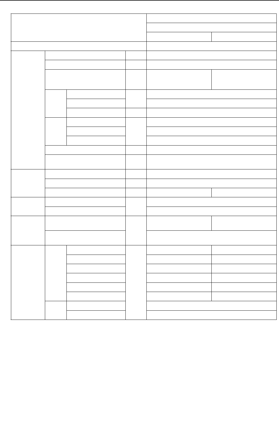
[ VIII Test Run Mode ]
- 220 -
HWE09080 GB
(2) Heating only operation
Item
2-unit combination
PQRY-P144YSHMU-A
PQRY-P72YHMU-A PQRY-P72YHMU-A
Model name of BC controller CMB-P108NU-GA
Operating
conditions
Indoor temperature DB/WB 21.1°C/- [70 °F/-]
Heat source water temperature °C [ °F] 21.1 [70]
Heat source water flow rate
m3/h
G/h
gpm
5.76
[1522]
[25.4]
5.76
[1522]
[25.4]
Indoor
unit
No. of connected units
Unit
4
No. of units in operation 4
Model 36/36/36/36
Pipe
length
Main pipe
m [ft]
5[16-3/8]
Branch pipe 10 [32-3/4]
Total pipe length 45 [147]
Fan speed Hi
Refrigerant charge kg
[lbs-oz] 20.3 [45]
Heat source
unit
Current A 25.5
Voltage V 230
Compressor frequency Hz 60 60
LEV opening
Indoor unit
Pulse
332/332/332/332
BC controller (1/2/3) 110/110/870
Pressure
switch
High pressure (63HS1)/
Low pressure (63LS) MPa
[psi]
2.64/0.80
[383/116]
2.64/0.80
[383/116]
BC controller on the liquid side
(PS1)/Intermediate part (PS3)
2.61/2.29
[378/332]
Sectional
temperatures
Heat
source
unit
Discharge (TH4)
°C [ °F]
77 [171] 77 [171]
Heat exchanger outlet 5 [41] 5 [41]
Accumulator inlet 4 [39] 4 [39]
Accumulator outlet 4 [39] 4 [39]
Compressor inlet 4 [39] 4 [39]
Compressor shell bottom 40 [104] 40 [104]
Indoor
unit
LEV inlet 37 [99]
Heat exchanger inlet 70 [158]
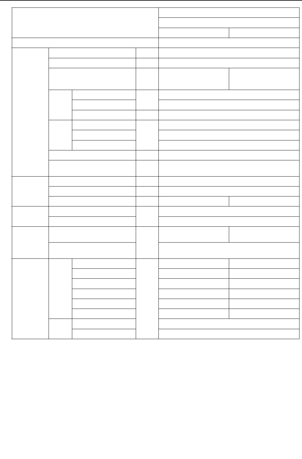
[ VIII Test Run Mode ]
- 221 -
HWE09080 GB
Item
2-unit combination
PQRY-P168YSHMU-A
PQRY-P96YHMU-A PQRY-P72YHMU-A
Model name of BC controller CMB-P108NU-GA
Operating
conditions
Indoor temperature DB/WB 21.1°C/- [70 °F/-]
Heat source water temperature °C [ °F] 21.1 [70]
Heat source water flow rate
m3/h
G/h
gpm
5.76
[1522]
[25.4]
5.76
[1522]
[25.4]
Indoor
unit
No. of connected units
Unit
4
No. of units in operation 4
Model 36/36/48/48
Pipe
length
Main pipe
m [ft]
5[16-3/8]
Branch pipe 10 [32-3/4]
Total pipe length 45 [147]
Fan speed Hi
Refrigerant charge kg
[lbs-oz] 23.1 [51]
Heat source
unit
Current A 44.3
Voltage V 230
Compressor frequency Hz 66 66
LEV opening
Indoor unit
Pulse
332/332/406/406
BC controller (1/2/3) 110/110/870
Pressure
switch
High pressure (63HS1)/
Low pressure (63LS) MPa
[psi]
2.80/0.80
[406/116]
2.80/0.80
[406/116]
BC controller on the liquid side
(PS1)/Intermediate part (PS3)
2.77/2.45
[402/355]
Sectional
temperatures
Heat
source
unit
Discharge (TH4)
°C [ °F]
77 [171] 77 [171]
Heat exchanger outlet 5 [41] 5 [41]
Accumulator inlet 4 [39] 4 [39]
Accumulator outlet 4 [39] 4 [39]
Compressor inlet 4 [39] 4 [39]
Compressor shell bottom 40 [104] 40 [104]
Indoor
unit
LEV inlet 37 [99]
Heat exchanger inlet 70 [158]

[ VIII Test Run Mode ]
- 222 -
HWE09080 GB
Item
2-unit combination
PQRY-P192YSHMU-A
PQRY-P96YHMU-A PQRY-P96YHMU-A
Model name of BC controller CMB-P108NU-GA
Operating
conditions
Indoor temperature DB/WB 21.1°C/- [70 °F/-]
Heat source water temperature °C [ °F] 21.1 [70]
Heat source water flow rate
m3/h
G/h
gpm
5.76
[1522]
[25.4]
5.76
[1522]
[25.4]
IIndoor
unit
No. of connected units
Unit
4
No. of units in operation 4
Model 48/48/48/48
Pipe
length
Main pipe
m [ft]
5[16-3/8]
Branch pipe 10 [32-3/4]
Total pipe length 45 [147]
Fan speed Hi
Refrigerant charge kg
[lbs-oz] 24.6 [55]
Heat source
unit
Current A 51.1
Voltage V 230
Compressor frequency Hz 72 72
LEV opening
Indoor unit
Pulse
406/406/406/406
BC controller (1/2/3) 110/110/980
Pressure
switch
High pressure (63HS1)/
Low pressure (63LS) MPa
[psi]
2.90/0.80
[421/116]
2.90/0.80
[421/116]
BC controller on the liquid side
(PS1)/Intermediate part (PS3)
2.87/2.55
[416/370]
Sectional
temperatures
Heat
source
unit
Discharge (TH4)
°C [ °F]
80 [176] 80 [176]
Heat exchanger outlet 5 [41] 5 [41]
Accumulator inlet 4 [39] 4 [39]
Accumulator outlet 4 [39] 4 [39]
Compressor inlet 4 [39] 4 [39]
Compressor shell bottom 40 [104] 40 [104]
Indoor
unit
LEV inlet 37 [99]
Heat exchanger inlet 70 [158]

[ VIII Test Run Mode ]
- 223 -
HWE09080 GB
Item
2-unit combination
PQRY-P216YSHMU-A
PQRY-P120YHMU-A PQRY-P96YHMU-A
Model name of BC controller CMB-P108NU-GA
Operating
conditions
Indoor temperature DB/WB 21.1°C/- [70 °F/-]
Heat source water temperature °C [ °F] 21.1 [70]
Heat source water flow rate
m3/h
G/h
gpm
5.76
[1522]
[25.4]
5.76
[1522]
[25.4]
Indoor
unit
No. of connected units
Unit
5
No. of units in operation 5
Model 36/36/48/48/48
Pipe
length
Main pipe
m [ft]
5[16-3/8]
Branch pipe 10 [32-3/4]
Total pipe length 65 [213]
Fan speed Hi
Refrigerant charge kg
[lbs-oz] 26.2 [58]
Heat source
unit
Current A 55.1
Voltage V 230
Compressor frequency Hz 81 81
LEV opening
Indoor unit
Pulse
332/332/406/406/406
BC controller (1/2/3) 110/110/1050
Pressure
switch
High pressure (63HS1)/
Low pressure (63LS) MPa
[psi]
2.75/0.80
[399/116]
2.75/0.80
[399/116]
BC controller on the liquid side
(PS1)/Intermediate part (PS3)
2.72/2.40
[395/348]
Sectional
temperatures
Heat
source
unit
Discharge (TH4)
°C [ °F]
81 [178] 81 [178]
Heat exchanger outlet 5 [41] 5 [41]
Accumulator inlet 4 [39] 4 [39]
Accumulator outlet 4 [39] 4 [39]
Compressor inlet 4 [39] 4 [39]
Compressor shell bottom 40 [104] 40 [104]
Indoor
unit
LEV inlet 35 [95]
Heat exchanger inlet 70 [158]

[ VIII Test Run Mode ]
- 224 -
HWE09080 GB
Item
2-unit combination
PQRY-P240YSHMU-A
PQRY-P120YHMU-A PQRY-P120YHMU-A
Model name of BC controller CMB-P108NU-GA
Operating
conditions
Indoor temperature DB/WB 21.1°C/- [70 °F/-]
Heat source water temperature °C [ °F] 21.1 [70]
Heat source water flow rate
m3/h
G/h
gpm
5.76
[1522]
[25.4]
5.76
[1522]
[25.4]
Indoor
unit
No. of connected units
Unit
6
No. of units in operation 6
Model 36/36/36/36/48/48
Pipe
length
Main pipe
m [ft]
5[16-3/8]
Branch pipe 10 [32-3/4]
Total pipe length 65 [213]
Fan speed Hi
Refrigerant charge kg
[lbs-oz] 26.2 [58]
Heat source
unit
Current A 33.5
Voltage V 230
Compressor frequency Hz 90 90
LEV opening
Indoor unit
Pulse
332/332/332/332/406/406
BC controller (1/2/3) 110/110/1120
Pressure
switch
High pressure (63HS1)/
Low pressure (63LS) MPa
[psi]
2.68/0.80
[389/116]
2.68/0.80
[389/116]
BC controller on the liquid side
(PS1)/Intermediate part (PS3)
2.64/2.32
[383/336]
Sectional
temperatures
Heat
source
unit
Discharge (TH4)
°C [ °F]
81 [178] 81 [178]
Heat exchanger outlet 5 [41] 5 [41]
Accumulator inlet 4 [39] 4 [39]
Accumulator outlet 4 [39] 4 [39]
Compressor inlet 4 [39] 4 [39]
Compressor shell bottom 40 [104] 40 [104]
Indoor
unit
LEV inlet 35 [95]
Heat exchanger inlet 70 [158]

- 225 -
HWE09080 GB
IX
Troubleshooting
[1] Error Code Lists.............................................................................................................227
[2] Responding to Error Display on the Remote Controller................................................. 230
[3] Investigation of Transmission Wave Shape/Noise......................................................... 303
[4] Troubleshooting Principal Parts..................................................................................... 306
[5] Refrigerant Leak ............................................................................................................ 343
[6] Compressor Replacement Instructions.......................................................................... 347
[7] Servicing the BC controller ............................................................................................ 353
[8] Troubleshooting Using the Heat source Unit LED Error Display ................................... 356

- 226 -
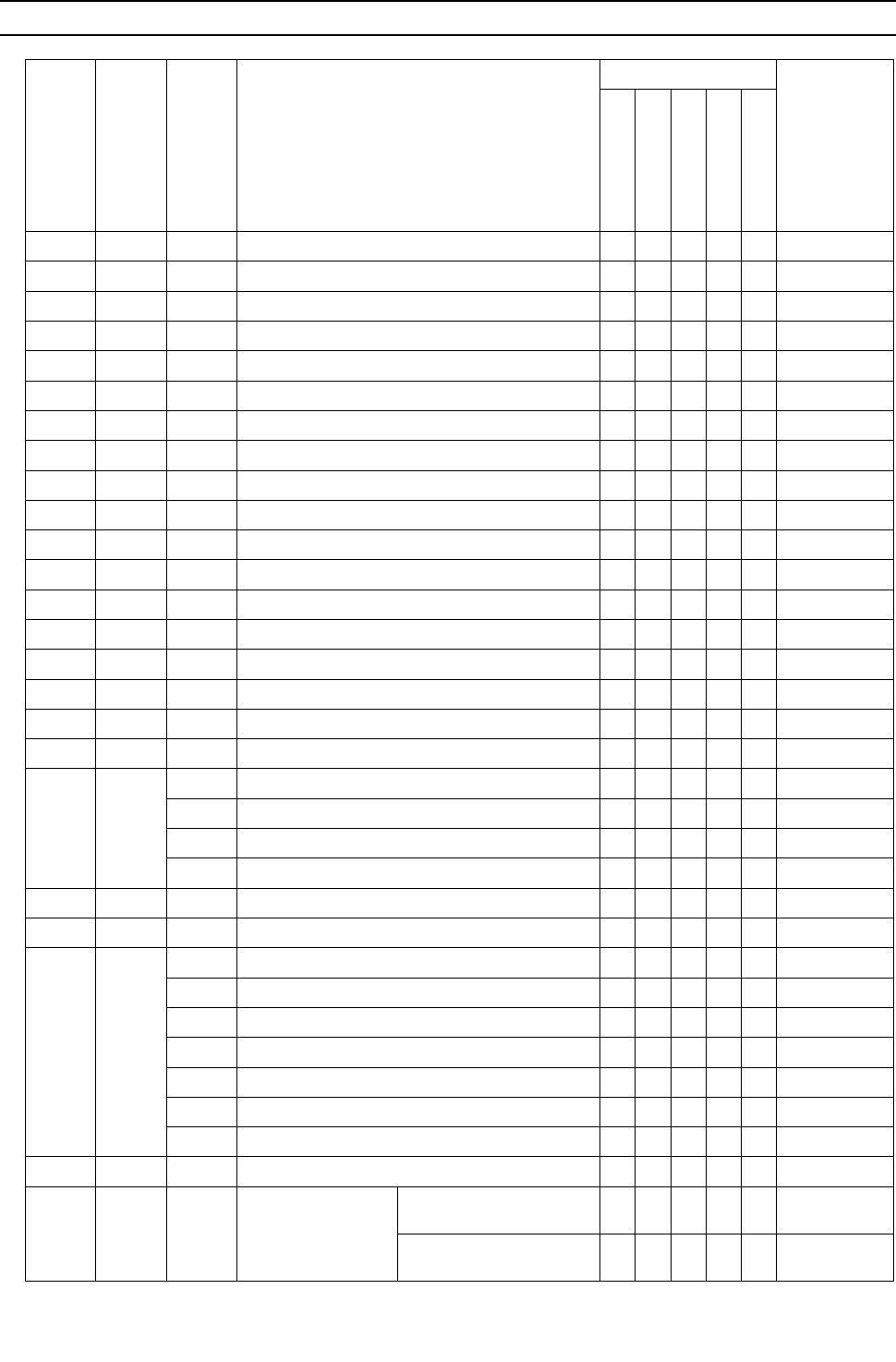
[ IX Troubleshooting ]
- 227 -
HWE09080 GB
IX Troubleshooting
[1] Error Code Lists
Error
Code
Prelimi-
nary
error
code
Error
(prelim-
inary)
detail
code
Error code definition
Searched unit
Notes
0403 4300 01 Serial communication error O
1102 1202 - Discharge temperature fault O
1301 - - Low pressure fault O
1302 1402 - High pressure fault O
1500 1600 - Refrigerant overcharge O
- 1605 - Preliminary suction pressure fault O
2000 2100 - Pump interlock error O
2134 2234 - Abnormal water temperature O
2135 2235 - Water heat exchanger freeze up O
2500 - - Drain sensor submergence O
2502 - - Drain pump fault O O
2503 - - Drain sensor (Thd) fault O O
2600 - - Water leakage O
2601 - - Water supply cutoff O
4102 4152 - Open phase O
4106 - - Transmission power supply fault O
4115 - - Power supply signal sync error O
4116 - - RPM error/Motor error O O
4220 4320
[108] Abnormal bus voltage drop O
[109] Abnormal bus voltage rise O
[111] Logic error O
[131] Low bus voltage at startup O
4230 4330 - Heatsink overheat protection O
4240 4340 - Overload protection O
4250 4350
[101] IPM error O
[102] ACCT overcurrent (H/W detection) O
[103] DCCT overcurrent (H/W detection) O
[104] Short-circuited IPM/Ground fault O
[105] Overcurrent error due to short-circuited motor O
[106] Instantaneous overcurrent O
[107] Overcurrent O
4260 - - Heatsink overheat protection at startup O
5101 1202 - Temperature sensor
fault
Return air temperature
(TH21) O
OA processing unit inlet
temperature (TH4) O
Heat source unit
Indoor unit
BC controller
LOSSNAY
Remote controller

[ IX Troubleshooting ]
- 228 -
HWE09080 GB
5102 1217 - Temperature sensor
fault
Indoor unit pipe tempera-
ture (TH22) O
OA processing unit pipe
temperature (TH2) O
HIC bypass circuit outlet
temperature (TH2) O
5103 1205 00 Temperature sensor
fault
Indoor unit gas-side pipe
temperature (TH23) O
OA processing unit gas-
side pipe temperature
(TH3)
O
Pipe temperature at heat
exchanger outlet (TH3) O
5104 1202 - Temperature sensor
fault
OA processing unit intake
air temperature (TH1) O
Outside temperature
(TH24) O
Detectable
only by the All-
Fresh type in-
door units
Heat source unit discharge
temperature (TH4) O
5105 1204 - Temperature sensor
fault
Accumulator inlet tempera-
ture (TH5) O
5106 1216 - Temperature sensor
fault
HIC circuit outlet tempera-
ture (TH6) O
5107 1221 - Temperature sensor
fault Water inlet pipe (TH7) O
5108 1218 - Temperature sensor
fault Water outlet pipe (TH8) O
5112 1215 - Temperature sensor
fault
Component cooler heat ex-
changer outlet (THINV) O
5110 1214 01 Temperature sensor
fault
Heatsink temperature
(THHS) O
5111 - -
Temperature sensor
fault
(BC controller)
Liquid inlet temperature
(TH11) O
5112 - - Bypass outlet temperature
(TH12) O
5115 - - LEV3 outlet temperature
(TH15) O
5116 - - LEV3 inlet temperature
(TH16) O
5201 - - High-pressure sensor fault (63HS1) O
5201 1402 - High-pressure sensor fault
(Heat source unit HPS/BC controller PS1) OO
5203 - - Intermediate pressure sensor fault
(BC controller PS3) O
Error
Code
Prelimi-
nary
error
code
Error
(prelim-
inary)
detail
code
Error code definition
Searched unit
Notes
Heat source unit
Indoor unit
BC controller
LOSSNAY
Remote controller
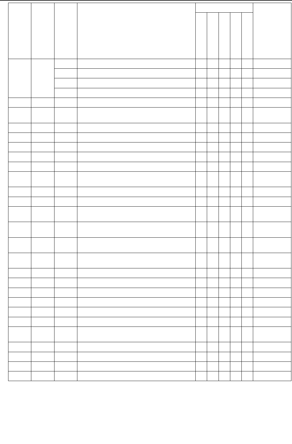
[ IX Troubleshooting ]
- 229 -
HWE09080 GB
5301 4300
[115] ACCT sensor fault O
[117] ACCT sensor circuit fault O
[119] Open-circuited IPM/Loose ACCT connector O
[120] Faulty ACCT wiring O
5701 - - Loose float switch connector O
6201 - - Remote controller board fault (nonvolatile memory
error) O
6202 - - Remote controller board fault (clock IC error) O
6600 - - Address overlaps O OOOO
6601 - - Polarity setting error O
6602 - - Transmission processor hardware error O OOOO
6603 - - Transmission line bus busy error O OOOO
6606 - - Communication error between device and trans-
mission processors OOOOO
6607 - - No ACK error O OOOO
6608 - - No response error O OOOO
6831 - - MA controller signal reception error (No signal re-
ception) OO
6832 - - MA remote controller signal transmission error
(Synchronization error) OO
6833 - - MA remote controller signal transmission error (H/
W error) OO
6834 - - MA controller signal reception error (Start bit de-
tection error) OO
7100 - - Total capacity error O
7101 - - Capacity code setting error O O O
7102 - - Wrong number of connected units O O
7105 - - Address setting error O
7106 - - Attribute setting error O
7107 - - Port setting error O
7110 - - Connection information signal transmission/recep-
tion error O
7111 - - Remote controller sensor fault O O
7113 - - Function setting error O
7117 - - Model setting error O
7130 - - Incompatible unit combination O
Error
Code
Prelimi-
nary
error
code
Error
(prelim-
inary)
detail
code
Error code definition
Searched unit
Notes
Heat source unit
Indoor unit
BC controller
LOSSNAY
Remote controller
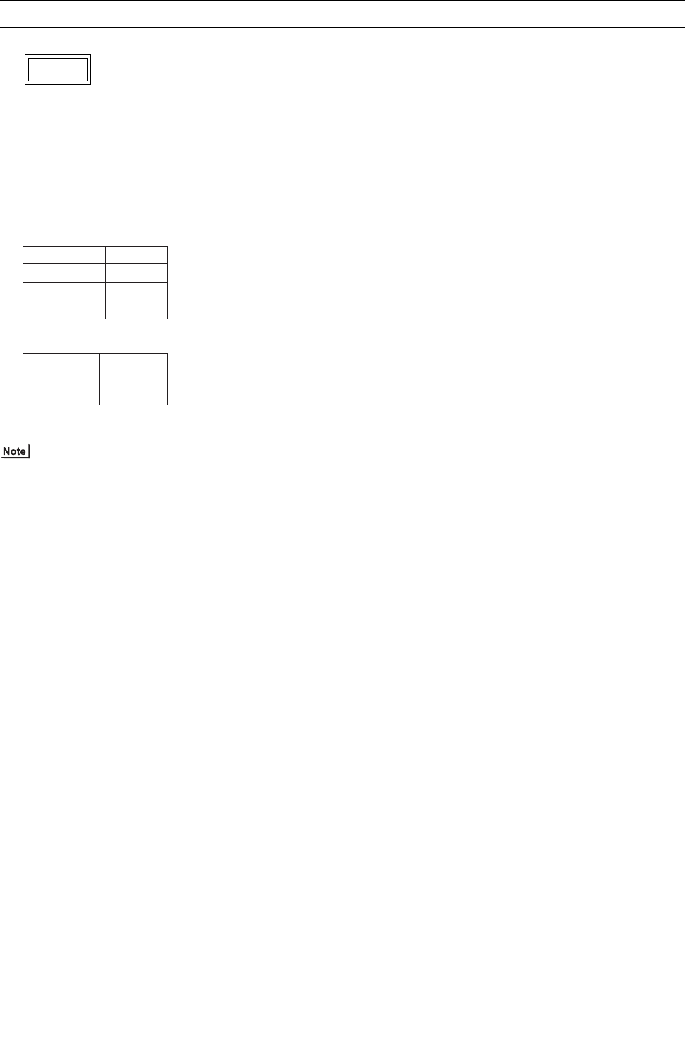
[ IX Troubleshooting ]
- 230 -
HWE09080 GB
[2] Responding to Error Display on the Remote Controller
1. Error Code
Serial communication error
2. Error definition and error detection method
Serial communication error between the control board and the INV board on the compressor.
Detail code 01: Between the control board and the INV board
3. Cause, check method and remedy
(1) Faulty wiring
Check the following wiring connections.
1) Between Control board and Fan board
2) Between Control board and INV board
(2) INV board failure and Control board failure
Replace the INV board or the Fan board when the power turns on automatically, even if the power source is reset.
Refer to section -6- "Inverter" under part [4] Troubleshooting Principal Parts for error codes related to the inverter.
0403
CN2 CN21
CN4 CN4
CN332 CN18V
Control board FAN board
CN2 CN2
CN4 CN4
Control board INV board
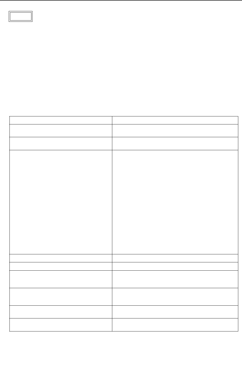
[ IX Troubleshooting ]
- 231 -
HWE09080 GB
1. Error Code
Discharge temperature fault
2. Error definition and error detection method
1) If the discharge temperature of 120 °C [248°F] or more is detected during the above operation (the first detection), the heat
source unit stops once, turns to anti-restart mode for 3 minutes, and restarts after 3 minutes automatically.
2) If the discharge temperature of 120° C [248°F] or more is detected again (the second detection) within 30 minutes after the
second stop of the heat source unit described above, the mode will be changed to 3 - minute restart mode, then the heat
source unit will restart in 3 minutes.
3) If the discharge temperature of 120°C [248°F] or more is detected (the third detection) within 30 minutes after the stop of the
heat source unit described above (regardless of the first or the second stop), the heat source unit will make an error stop, and
the error code "1102" will be displayed.
4) If the discharge temperature of 120°C [248°F] or more is detected more than 30 minutes after the previous stop of the heat
source unit, the detection is regarded as the first detection, and the operation described in step 1 above will start.
5) For 30 minutes after the stop (the first stop or the second stop) of the heat source unit, preliminary errors will be displayed on
the LED display.
3. Cause, check method and remedy
1102
Cause Check method and remedy
(1) Gas leak, gas shortage Refer to the page on refrigerant amount
evaluation.(page 177)
(2) Overload operation Check operating conditions and operation status of indoor/
heat source units.
(3) LEV failure on the indoor unit Perform a heating operation and check the operation.
Cooling: LEV on the indoor unit
BC controller LEV1,2,3
Heat source unit LEV2a,2b
BC controller SVM1,2
BC controller SVA,C
Heating: LEV on the indoor unit
Heat source unit LEV2a,2b
BC controller LEV3
BC controller SVB
BC controller SV4a - 4d
Refer to the page on troubleshooting LEV.(page 310)
(4) BC controller LEV malfunction
Cooling only : LEV3
Cooling main : LEV1,2,3
Heating only or heating
main : LEV3
(5) BC controller SVM1 and 2 malfunction
-> Cooling only or defrost
(6) BC controller SVA malfunction
-> Cooling only or cooling main
(7) BC controller SVB malfunction
-> Heating only or heating main
(8) Solenoid valve SV malfunction 4a-4d,7a,7b
:heating only, heating main
(9) Heat source unit LEV1 actuation failure
Heat source unit LEV2a and LEV2b actuation
failure
(10) Port address setting error. Confirm the port address of the indoor unit.
(11) Closed ball valve Confirm that the ball valve is fully open.
(12) Insufficient heat source water flow, heat
source water supply cutoff, dirty or clogged
water heat exchangerHeating
Check the water heat exchanger for clogging.
Check the heat source water circulation pump.
(13) Gas leak between low and high pressures
(4-way valve failure, Compressor failure, So-
lenoid valve (SV1a) failure)
Perform a cooling or heating operation and check the opera-
tion.
(14) Thermistor failure
(TH4)
Check the thermistor resistor.(page 260)
(15) Input circuit failure on the controller board
thermistor
Check the inlet air temperature on the LED monitor.

[ IX Troubleshooting ]
- 232 -
HWE09080 GB
1. Error Code
Low pressure fault
2. Error definition and error detection method
When starting the compressor from Stop Mode for the first time if low pressure reads 0.098MPa [14psi] immediately before
start-up, the operation immediately stops.
3. Cause, check method and remedy
1301
Cause Check method and remedy
(1) Inner pressure drop due to a leakage. Refer to the section on troubleshooting the low pressure
sensor.(page 307)
(2) Low pressure sensor failure
(3) Short-circuited pressure sensor cable due to
torn outer rubber
(4) A pin on the male connector is missing.
(5) Disconnected wire
(6) Failure of the low pressure input circuit on the
controller board
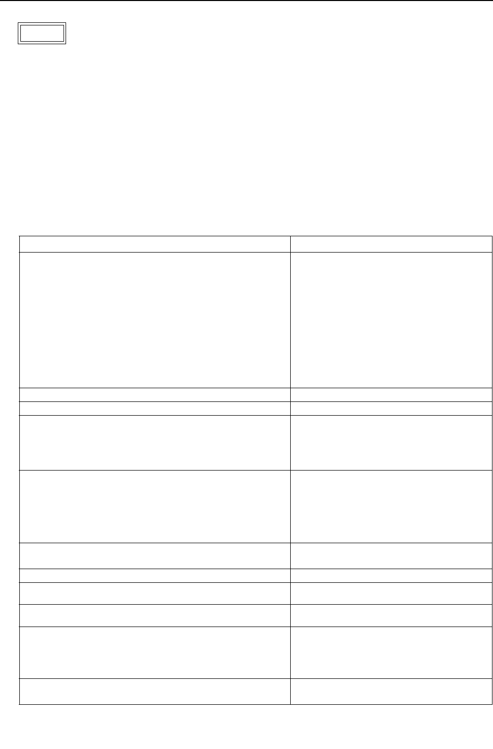
[ IX Troubleshooting ]
- 233 -
HWE09080 GB
1. Error Code
High pressure fault 1 (Heat source unit)
2. Error definition and error detection method
1) If the pressure of 3.78MPa [548psi] or higher is detected by the pressure sensor during operation (the first detection), the heat
source stops once, turns to antirestart mode for 3 minutes, and restarts after 3 minutes automatically.
2) If the pressure of 3.78MPa [548psi] or higher is detected by the pressure sensor again (the second detection) within 30 min-
utes after the first stop of the heat source unit, the heat source unit stops once, turns to anti-restart mode for 3 minutes, and
restarts after 3 minutes automatically.
3) If the pressure of 3.87MPa [561psi] or higher is detected by the pressure sensor (the third detection) within 30 minutes of the
second stop of the heat source unit, the heat source unit will make an error stop, and the error code "1302" will be displayed.
4) If the pressure of 3.78MPa [548psi] or higher is detected more than 30 minutes after the stop of the heat source unit, the de-
tection is regarded as the first detection, and the operation described in step 1 above will start.
5) For 30 minutes after the stop of the heat source unit, preliminary errors will be displayed on the LED display.
6) The heat source unit makes an error stop immediately when not only the pressure sensor but also the pressure switch detects
4.15+0,-0.15 MPa [601+0,-22 psi]
3. Cause, check method and remedy
1302
Cause Check method and remedy
(1) Indoor unit LEV actuation failure Heating Perform a heating operation and check the op-
eration.
Cooling: LEV on the indoor unit
Heat source unit LEV1,2,3
BC controller LEV2a,2b
BC controller SVM1,1b,2,2b
BC controller SVA
Heating: LEV on the indoor unit
BC controller LEV3
BC controller SVM2,2b
BC controller SVB,SV4a - 4d
Refer to the page on troubleshooting for LEV
and solenoid valve.(page 310)
(2) BC controller LEV malfunction Heating only or heating main :
Indoor LEV 3
(3) BC controller SVM1 and 2 malfunction
->Cooling only
(4) BC controller SVA and SVC malfunction
->Cooling only or cooling main
(5) BC controller SVB malfunction ->Heating only or heating main
Solenoid valve SV malfunction 4a-4d ->Cooling only or cooling
main
(6) Heat source unit LEV2a and LEV2b actuation failureCooling
(7) Port address setting error. Confirm the port address of the indoor unit.
(8) Refrigerant service valve actuation failure Confirm that the refrigerant service valve is fully
(9) Short cycle on the indoor unit side Check the indoor units for problems and correct
them, if any.
(10) Clogged filter on the indoor unit
(11) Reduced air flow due to dirty fan on the indoor unit fan
(12) Dirty heat exchanger of the indoor unit
(13) Insufficient heat source water flow Check the water heat exchanger for clogging.
Check the heat source water circulation pump.
(14) Heat source water supply cutoff
(15) Dirty or clogged water heat exchanger
Items (13) through (15) above reduce the condensing capabil-
ity of the unit, resulting in high-pressure rise during heating op-
eration.
(16) Solenoid valve (SV1a) malfunction
The by-pass valve (SV1a) can not control rise in high pressure.
Refer to the section on troubleshooting the so-
lenoid valve.(page 308)
(17) Thermistor failure (TH3, TH7) Check the thermistor resistor.(page 260)
(18) Pressure sensor failure Refer to the page on the troubleshooting of the
high pressure sensor. (page 306)
(19) Failure of the thermistor input circuit and pressure sensor input
circuit on the controller board
Check the sensor temperature/pressure on the
LED monitor.
(20) Thermistor mounting problem (TH3, TH7) Check the sensor temperature/pressure on the
LED monitor.
(21) Disconnected male connector on the pressure switch (63H1) or
disconnected wire
(22) Voltage drop caused by unstable power supply voltage Check the input voltage at the power supply ter-
minal TB1.
[ IX Troubleshooting ]
- 234 -
HWE09080 GB
1. Error Code
High pressure fault 2 (Heat source unit)
2. Error definition and error detection method
If the pressure of 0.098MPa [14psi] or lower is registered on the pressure sensor immediately before start-up, it will trigger an
abnormal stop, and error code "1302" will be displayed.
3. Cause, check method and remedy
1. Error Code
Refrigerant overcharge
2. Error definition and error detection method
An error can be detected by the discharge temperature superheat.
1) If the formula "TdSH 10°C [18°F]" is satisfied during operation (first detection), the heat source unit stops, goes into the 3-
minute restart mode, and starts up in three minutes.
2) If the formula "TdSH 10°C [18°F]" is satisfied again within 30 minutes of the first stoppage of the heat source unit (second
detection), the unit comes to an abnormal stop, and the error code "1500" appears.
3) If the formula "TdSH 10°C [18°F]" is satisfied 30 minutes or more after the first stoppage of the heat source unit, the same
sequence as Item "1 above (first detection) is followed.
4) For 30 minutes after the stop of the heat source unit, preliminary errors will be displayed on the LED display.
3. Cause, check method and remedy
1302
Cause Check method and remedy
(1) Inner pressure drop due to a leakage. Refer to the page on the troubleshooting of the high
pressure sensor.(page 306)
(2) Pressure sensor failure
(3) Shorted-circuited pressure sensor cable due to torn
outer rubber
(4) A pin on the male connector on the pressure sensor
is missing or contact failure
(5) Disconnected pressure sensor cable
(6) Failure of the pressure sensor input circuit on the
controller board
1500
Cause Check method and remedy
(1) Overcharged refrigerant Refer to the page on refrigerant amount
evaluation.(page 177)
(2) Thermistor input circuit failure on the control board Check the temperature and pressure readings on the sen-
sor that are displayed on the LED monitor.
(3) Faulty mounting of thermistor (TH4) Check the temperature and pressure readings on the
thermistor that are displayed on the LED monitor.
(4) Heat source unit LEV2a and LEV2b actuation fail-
ureHeating
Refer to the section on troubleshooting the LEV.
(page 310)
[ IX Troubleshooting ]
- 235 -
HWE09080 GB
1. Error Code
Pump interlock error
2. Error definition and error detection method
1) This error is detected by the pump interlock circuit (TB8 3-4).
2) If it is detected that the pump interlock circuit (TB8 3-4) is open (first detection) during operation or immediately before startup,
the heat source unit stops and goes into the 10-minute restart delay mode.
3) If the pump interlock circuit (TB8 3-4) has remained open for continuous 10 minutes (second detection) since the first stoppage
of the heat source unit, the unit will make an abnormal stop, and the error code "2000" appears on the LED.
4) For the 10 minutes from the time the heat source stopped is considered a preliminary error, and it is indicated on the LED.
5) This error is indicated on the LED only when Dip switch SW2-8 on the control board of the heat source unit is set to OFF.
3. Cause, check method and remedy
2000
Cause Check method and remedy
(1) Heat source water circulation pump fault Operate the pump, and check for proper operation.
(2) Broken wire Check the field wiring for proper installation and conduc-
tion.
(3) Loose connectors or contact failure Check the connectors for proper connection.
(4) Interlock signal input circuit fault on the relay board
(5) Interlock signal input circuit fault on the control
board
[ IX Troubleshooting ]
- 236 -
HWE09080 GB
1. Error Code
Abnormal water temperature
2. Error definition and error detection method
1) If a water inlet pipe temperature (TH7) of 5°C[41ºF] or below OR 50°C[122ºF] or above is detected (first detection) during op-
eration, the heat source unit stops, goes into the 3-minute restart delay mode, and automatically restarts after three minutes.
2) If a water inlet pipe temperature (TH7) of 5°C[41ºF] or below OR 50°C[122ºF] or above is detected again (second detection)
within 30 minutes of the first stoppage of the heat source unit, the unit will make an abnormal stop, and the error code "2134"
appears on the LED.
3) If a water inlet pipe temperature (TH7) of 5°C[41ºF] or below OR 50°C[122ºF] or above is detected after 30 minutes of the first
stoppage of the heat source unit, this is considered as the first detection, and the sequence as described in section 1) above
is followed.
4) The period of 30 minutes after a stoppage of the heat source unit is considered a preliminary error, and a preliminary error
code appears on the LED display.
3. Cause, check method and remedy
2134
Cause Check method and remedy
(1) Heat source water circulation pump fault Operate the pump, and check for proper operation.
(2) Cooling tower or heater problem Check the cooling tower and heater, and correct any prob-
lems found.
(3) Thermistor fault (TH7) Check thermistor resistance.
(4) Thermistor signal input circuit fault on the control
board
Check the sensor reading on the LED.
(5) Improper installation of thermistor (TH7) Check the sensor reading on the LED.
[ IX Troubleshooting ]
- 237 -
HWE09080 GB
1. Error Code
Water heat exchanger freeze up
2. Error definition and error detection method
1) If either of the following conditions is detected (first detection) during operation, the heat source unit stops, goes into the 3-
minute restart delay mode, and automatically restarts after three minutes.
Water outlet pipe temperature (TH8) of 4°C[39ºF] or below is detected.
All of the following conditions are continuously met for one minute during Heating-all or Heating-main operation: Compres-
sor frequency < Minimum frequency + 20 AND Evaporation temperature (Te) < -2ºC[28°F] AND Accumulator inlet pipe tem-
perature (TH5) 3°C[37ºF].
2) If the conditions above (1) are met again within 60 minutes of the first stoppage of the heat source unit (second detection),
the unit will make an abnormal stop, and the error code "2135" will appear on the LED.
3) If the conditions above (1) are met again after 60 minutes of the first stoppage of the heat source unit, it is considered the first
detection, and the sequence as described in section 1) above is followed.
4) For the 60 minutes from the time the heat source stopped is considered a preliminary error, and it is indicated on the LED.
3. Cause, check method and remedy
2135
Cause Check method and remedy
(1) Heat source water circulation pump fault Operate the pump, and check for proper operation.
(2) Heater problem Check the heater, and correct any problems found.
(3) Poorly maintained field-installed water pipes Identify and remove the cause of water flow reduction, such
as a clogged strainer or cavitation.
(4) Dirty or clogged water heat exchanger Check the pressure difference between the unit's inlet and
outlet.
(5) Thermistor fault (TH5, TH8) Check thermistor resistance.
(6) Thermistor signal input circuit fault on the control
board
Check the sensor reading on the LED.
(7) Improper installation of thermistor (TH5, TH8) Check the sensor reading on the LED.
[ IX Troubleshooting ]
- 238 -
HWE09080 GB
1. Error Code
Drain sensor submergence (Models with a drain sensor)
2. Error definition and error detection method
1) If an immersion of the drain sensor in the water is detected while the unit is in any mode other than the Cool/Dry mode and
when the drain pump goes from OFF to ON, this condition is considered preliminary water leakage. While this error is being
detected, humidifier output cannot be turned on.(Applicable to the units manufactured in or after October 1996)
2) If the immersion of the sensor in the water is detected four consecutive times at an hour interval, this is considered water leak-
age, and "2500" appears on the monitor.
3) Detection of water leakage is also performed while the unit is stopped.
4) Preliminary water leakage is cancelled when the following conditions are met:
One hour after the preliminary water leakage was detected, it is not detected that the drain pump goes from OFF to ON.
The operation mode is changed to Cool/Dry.
Liquid pipe temperature - inlet temperature -10°C[ -18°F]
3. Cause, check method and remedy
2500
Cause Check method and remedy
(1) Drain water drainage problem
Clogged drain pump
Clogged drain piping
Backflow of drain water from other units
Check for proper drainage.
(2) Adhesion of water drops to the drain sensor
Trickling of water along the lead wire
Rippling of drain water caused by filter clogging
1) Check for proper lead wire installation.
2) Check for clogged filter.
(3) Failure of the relay circuit for the solenoid valve Replace the relay.
(4) Indoor unit control board failure
Drain sensor circuit failure
If the above item checks out OK, replace the indoor unit
control board.
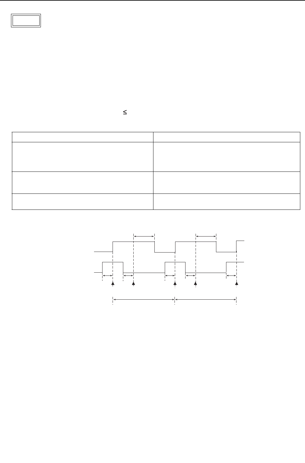
[ IX Troubleshooting ]
- 239 -
HWE09080 GB
1. Error Code
Drain sensor submergence (Models with a float switch)
2. Error definition and error detection method
1) If an immersion of the float switch in the water is detected while the unit is in any mode other than the Cool/Dry mode and
when the drain pump goes from OFF to ON, this condition is considered preliminary water leakage. While this error is being
detected, humidifier output cannot be turned on.
2) If the drain pump turns on within one hour after preliminary water leakage is detected and the above-mentioned condition is
detected two consecutive times, water leakage error water leakage is detected, and "2500" appears on the monitor.
3) Detection of water leakage is also performed while the unit is stopped.
4) Preliminary water leakage is cancelled when the following conditions are met:
One hour after the preliminary water leakage was detected, it is not detected that the drain pump goes from OFF to ON.
The operation mode is changed to Cool/Dry.
Liquid pipe temperature - inlet temperature - 10°C[-18°F]
3. Cause, check method and remedy
<Reference>
2500
Cause Check method and remedy
(1) Drain water drainage problem
Clogged drain pump
Clogged drain piping
Backflow of drain water from other units
Check for proper drainage.
(2) Stuck float switch
Check for slime in the moving parts of the float
switch.
Check for normal operation of the float switch.
(3) Float switch failure Check the resistance with the float switch turned on and
turned off.
6 minutes6 minutes
15
seconds 15
seconds 15
seconds 15
seconds 15
seconds
ON
OFF
ON
OFF
Drain pump operation triggered by a submergence of the liquid level sensor
(except during the Cooing/Dry mode)
Drain pump
output
Float switch
input
Submergence of
the sensor
Submergence of
the sensor
Preliminary water leakage
Submergence of
the sensor
Water leakage
Sensor in the airSensor in the air
Within 1-hour periodWithin 1-hour period
[ IX Troubleshooting ]
- 240 -
HWE09080 GB
1. Error Code
Drain pump fault (Models with a drain sensor)
2. Error definition and error detection method
1) Make the drain sensor thermistor self-heat. If the temperature rise is small, it is interpreted that the sensor is immersed in
water. This condition is considered to be a preliminary error, and the unit goes into the 3-minute restart delay mode.
2) If another episode of the above condition is detected during the preliminary error, this is considered a drain pump error, and
"2502" appears on the monitor.
3) This error is always detected while the drain pump is in operation.
4) The following criteria are met when the criteria for the forced stoppage of heat source unit (system stoppage) are met.
"Liquid pipe temperature - inlet temperature - 10 °C [ -18°F] " has been detected for 30 minutes.
The immersion of drain sensor is detected 10 consecutive times.
The conditions that are listed under items 1) through 3) above are always met before the criteria for the forced stoppage
of the heat source unit.
5) The indoor unit that detected the conditions that are listed in item 4) above brings the heat source unit in the same refrigerant
circuit to an error stop (compressor operation prohibited), and the heat source unit brings all the indoor units in the same re-
frigerant circuit that are in any mode other than Fan or Stop to an error stop. "2502" appears on the monitor of the units that
came to an error stop.
6) Forced stoppage of the heat source unit
Detection timing: The error is detected whether the unit is in operation or stopped.
7) Ending criteria for the forced stoppage of heat source unit
Power reset the indoor unit that was identified as the error source and the heat source unit that is connected to the same
refrigerant circuit.
Forced stoppage of the heat source unit cannot be cancelled by stopping the unit via the remote controller.
(Note) Items 1) - 3) and 4) - 7) are detected independently from each other.
The address and attribute that appear on the remote controller are those of the indoor unit (or OA processing unit)
that caused the error.
3. Cause, check method and remedy
2502
Cause Check method and remedy
(1) Drain pump failure Check for proper functioning of the drain pump.
(2) Drain water drainage problem
Clogged drain pump
Clogged drain piping
Check for proper drainage.
(3) Adhesion of water drops to the drain sensor
Trickling of water along the lead wire
Rippling of drain water caused by filter clogging
1) Check for proper lead wire installation.
2) Check for clogged filter.
(4) Indoor unit control board failure
Drain pump drive circuit failure
Drain heater output circuit failure
If the above item checks out OK, replace the indoor unit
control board.
(5) Items (1) through (4) above and an indoor unit elec-
tronic valve closure failure (leaky valve) occurred si-
multaneously.
Check the solenoid valves on the indoor unit for leaks.
[ IX Troubleshooting ]
- 241 -
HWE09080 GB
1. Error Code
Drain pump fault (Models with a float switch)
2. Error definition and error detection method
1) The immersion of sensor tip in water is detected by the ON/OFF signal from the float switch.
Submergence of the sensor
When it is detected that the float switch has been ON for 15 seconds, it is interpreted that the sensor tip is immersed in
water.
Sensor in the air
When it is detected that the float switch has been OFF for 15 seconds, it is interpreted that the sensor tip is not immersed
in water.
2) If it is detected that the float switch has been ON for 3 minutes after the immersion of the sensor tip was detected, this is con-
sidered a drain pump failure, and "2502" appears on the monitor.
The total time it takes for this error to be detected is 3 minutes and 15 seconds, including the time it takes for the first im-
mersion of the sensor tip to be detected.
3) Detection of drain pump failure is performed while the unit is stopped.
4) The following criteria are met when the criteria for the forced stoppage of heat source unit (system stoppage) are met.
"Liquid pipe temperature - inlet temperature - 10°C [ -18°F] " has been detected for 30 minutes.
It is detected by the float switch that the sensor tip has been immersed in water for 15 minutes or more.
The conditions that are listed under items 1) through 3) above are always met before the criteria for the forced stoppage
of the heat source unit.
5) The indoor unit that detected the conditions that are listed in item 4) above brings the heat source unit in the same refrigerant
circuit to an error stop (compressor operation prohibited), and the heat source unit brings all the indoor units in the same re-
frigerant circuit that are in any mode other than Fan or Stop to an error stop.
6) Forced stoppage of the heat source unit
Detection timing: The error is detected whether the unit is in operation or stopped.
This error is detected whether the unit is in operation or stopped.
7) Ending criteria for the forced stoppage of heat source unit
Power reset the indoor unit that was identified as the error source and the heat source unit that is connected to the same
refrigerant circuit.
Forced stoppage of the heat source unit cannot be cancelled by stopping the unit via the remote controller.
(Note) Items 1) - 3) and 4) - 7) are detected independently from each other.
The address and attribute that appear on the remote controller are those of the indoor unit (or OA processing unit)
that caused the error.
3. Cause, check method and remedy
2502
Cause Check method and remedy
(1) Drain pump failure Check for proper functioning of the drain pump
mechanism
(2) Drain water drainage problem
Clogged drain pump
Clogged drain piping
Check for proper drainage.
(3) Stuck float switch
Check for slime in the moving parts of the float switch.
Check for normal operation of the float switch.
(4) Float switch failure Check the resistance with the float switch turned
on and turned off.
(5) Indoor unit control board failure
Drain pump drive circuit failure
Float switch input circuit failure
Replace indoor unit control board.
(6) Items (1) through (5) above and an indoor unit electronic
valve closure failure (leaky valve) occurred simultane-
ously.
Check the solenoid valves on the indoor unit for
leaks.
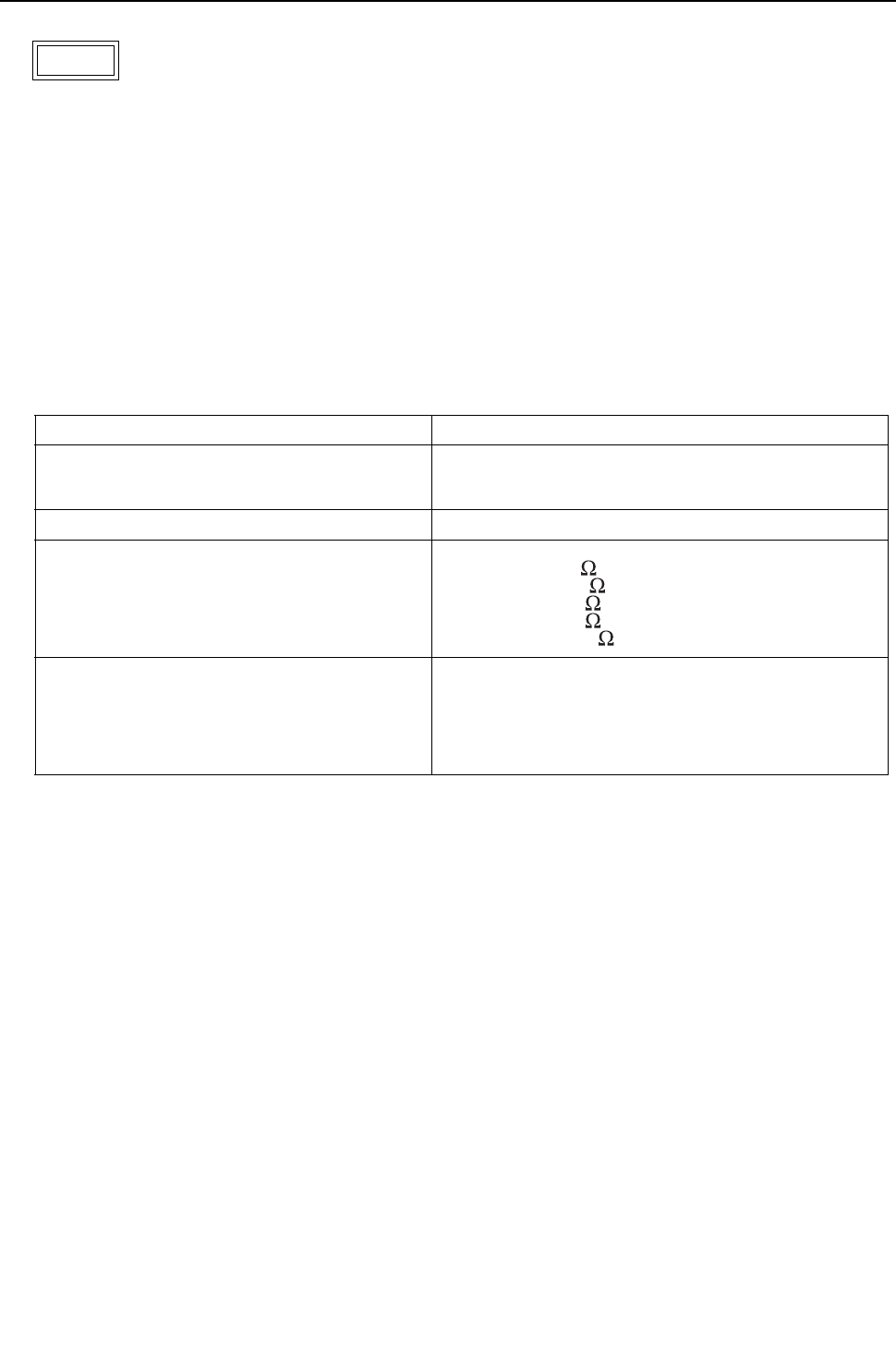
[ IX Troubleshooting ]
- 242 -
HWE09080 GB
1. Error Code
Drain sensor (Thd) fault
2. Error definition and error detection method
If the open or short circuit of the thermistor has been detected for 30 seconds, this condition is considered to be a preliminary
error, and the unit goes into the 3-minute restart delay mode.
If another episode of the above condition is detected during the preliminary error, this is considered a drain sensor error.(If
the short or open circuit of the thermistor is no longer detected, normal operation will be restored in 3 minutes.)
This error is detected when one of the following conditions are met.
During Cool/Dry operation
Liquid pipe temperature minus inlet temperature is equal to or smaller than - 10°C[ -18°F] (except during the defrost cycle)
When the liquid temperature thermistor or suction temperature thermistor or short or open circuited.
Drain pump is in operation.
One hour has elapsed since the drain sensor went off.
Short: 90 °C [194 °F] or above
Open: - 20 °C [-4 °F] or below
3. Cause, check method and remedy
2503
Cause Check method and remedy
(1) Faulty connector (CN31) insertion. 1) Check for connector connection failure.
Reinsert the connector, restart the operation, and check for
proper operation.
(2) Broken or semi-broken thermistor wire 2) Check for a broken thermistor wire.
(3) Thermistor failure 3) Check the resistance of the thermistor.
0°C[32 °F]:6.0k
10°C[50 °F]:3.9k
20°C[68°F]:2.6k
30°C[86°F]:1.8k
40°C[104 °F]:1.3k
(4) Indoor unit control board (error detection circuit)
failure
4) Replace the indoor unit control board if the problem recurs
when the unit is operated with the No.-1 and No.-2 pins on
the drain sensor connector (CN31) being short-circuited.
If the above item checks out OK, there are no problems with
the drain sensor.
Turn off the power and turn it back on.
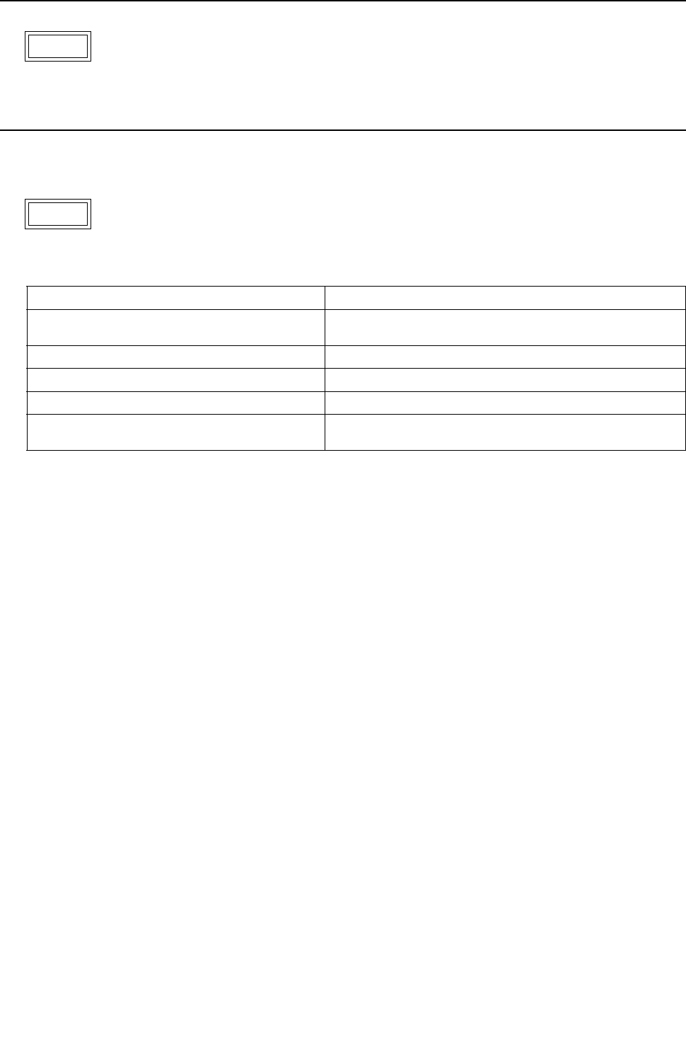
[ IX Troubleshooting ]
- 243 -
HWE09080 GB
1. Error Code
Water leakage
2. Cause, check method and remedy
Check that water does not leak from the pipes in such as the humidifier.
1. Error Code
Water supply cutoff
2. Cause, check method and remedy
2600
2601
Cause Check method and remedy
(1) The water tank of the humidifier is empty. Check the amount of supply water.
Check for the solenoid valve and for the connection.
(2) The solenoid valve for humidification is OFF. Check the connector.
(3) Disconnected float switch Check the connecting part.
(4) Poor operation of float switch Check for the float switch.
(5) Frozen water tank Turn off the power source of the water tank to defrost, and
turn it on again.

[ IX Troubleshooting ]
- 244 -
HWE09080 GB
1. Error Code
Open phase
2. Error definition and error detection method
An open phase of the power supply (L1 phase, L2 phase) was detected at power on.
The L3 phase current is outside of the specified range.
The open phase of the power supply may not always be detected if a power voltage from another circuit is applied.
3. Cause, check method and remedy
4102 (THMU-A)
Cause Check method and remedy
(1) Power supply problem
Open phase voltage of the power supply
Power supply voltage drop
Check the input voltage to the power supply terminal block TB1.
(2) Noise filter problem
Coil problem
Circuit board failure
Check the coil connections.
Check for coil burnout.
Confirm that the voltage at the CN02 connector is 188 V or
above.
(3) Wiring failure Confirm that the voltage at the control board connector CNAC is
188 V or above.
If the voltage is below 188V, check the wiring connection between
the noise filter board CN02 and control board CNAC.
Confirm that the wiring between TB23 and INV board SC-T is put
through CT3.
(4) Blown fuse Check that F01 on the control board is not blown.
->If a blown fuse is found, check for a short-circuiting or earth fault
of the actuator.
(5) CT3 failure Replace the inverter if this problem is detected after the compres-
sor has gone into operation.
(6) Control board failure Replace the control board if none of the above is causing the
problem.
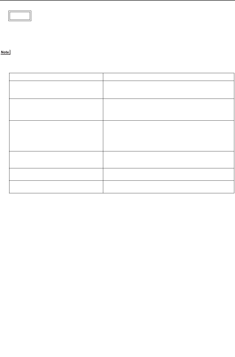
[ IX Troubleshooting ]
- 245 -
HWE09080 GB
1. Error Code
Open phase
2. Error definition and error detection method
An open phase of the power supply (L1 phase, L2 phase) was detected at power on.
The L3 phase current is outside of the specified range.
The open phase of the power supply may not always be detected if a power voltage from another circuit is applied.
3. Cause, check method and remedy
4102 (YHMU-A)
Cause Check method and remedy
(1) Power supply problem
Open phase voltage of the power supply
Power supply voltage drop
Check the input voltage to the power supply terminal block TB1.
(2) Noise filter problem
Coil problem
Circuit board failure
Check the coil connections.
Check for coil burnout.
Check that the voltage across TB21 and TB22 on the noise filter
board is 414V or above.
(3) Wiring failure Confirm that the voltage at the control board connector CNAC is
190 V or above.
If the voltage is below 190, check the wiring between noise filter
CN6, noise filter CN2, transformer box, and control board CNAC.
Confirm that the wiring between noise filter TB23 and INV board
SC-L3 is put through CT3.
(4) Blown fuse Check F01 on the control board, F4, and F5 for a blown fuse.
->If a blown fuse is found, check for a short-circuiting or earth fault
of the actuator.
(5) CT3 failure Replace the inverter if this problem is detected after the compres-
sor has gone into operation.
(6) Control board failure Replace the control board if none of the above is causing the
problem.

[ IX Troubleshooting ]
- 246 -
HWE09080 GB
1. Error Code
<Transmission power supply fault error detail FF (Heat source unit)>
2. Error definition and error detection method
Transmission power output failure
3. Cause
1) Wiring failure
2) Transmission power supply cannot output voltage because overcurrent was detected.
3) Voltage cannot be output due to transmission power supply problem.
4) Transmission voltage detection circuit failure
4. Check method and remedy
Check the items in IX [4] -7- (2) Troubleshooting transmission power circuit of heat source unit on all heat source units in the
same refrigerant circuit.
<Transmission power supply fault other than error detail code FF (Heat source unit)>
2. Error definition and error detection method
Transmission power reception failure
3. Cause
One of the heat source units stopped supplying power, but no other heat source units start supplying power.
4. Check method and remedy
Check the items in IX [4] -7- (2) Troubleshooting transmission power circuit of heat source unit on all heat source units in the
same refrigerant circuit.
4106
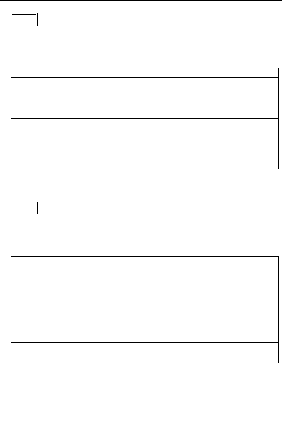
[ IX Troubleshooting ]
- 247 -
HWE09080 GB
1. Error Code
Power supply signal sync error
2. Error definition and error detection method
The frequency cannot be determined when the power is switched on.
3. Cause, check method and remedy
1. Error Code
Power supply signal sync error
2. Error definition and error detection method
The frequency cannot be determined when the power is switched on.
3. Cause, check method and remedy
4115 (THMU-A)
Cause Check method and remedy
(1) Power supply error Check the voltage of the power supply terminal
block (TB1).
(2) Noise filter problem
Coil problem
Circuit board failure
Check the coil connections.
Check for coil burnout.
Confirm that the voltage at the CN02 connector is
188 V or above.
(3) Faulty wiring Check fuse F01 on the control board.
(4) Wiring failure
Between noise filter board CN02 and control board
CNAC
Confirm that the voltage at the control board con-
nector CNAC is 188 V or above.
(5) Control board failure If none of the items described above is applicable,
and if the trouble reappears even after the power is
switched on again, replace the control board.
4115 (YHMU-A)
Cause Check method and remedy
(1) Power supply error Check the voltage of the power supply terminal
block (TB1).
(2) Noise filter problem
Coil problem
Circuit board failure
Check the coil connections.
Check for coil burnout.
Check that the voltage across TB21 and TB22 on
the noise filter board is 414V or above.
(3) Faulty wiring Check F01 on the control board, F4, and F5 for a
blown fuse.
(4) Wiring failure
Between noise filter CN2, transformer box, and control
board CNAC
Confirm that the voltage at the control board con-
nector CNAC is 190 V or above.
(5) Control board failure If none of the items described above is applicable,
and if the trouble reappears even after the power is
switched on again, replace the control board.

[ IX Troubleshooting ]
- 248 -
HWE09080 GB
1. Error Code
RPM error/Motor error
2. Error definition and error detection method
LOSSNAY
The motor keep running even if the power is OFF.
The thermal overload relay is ON. (Only for the three-phase model)
Indoor unit
If detected less than 180rpm or more than 2000rpm, the indoor unit will restart and keep running for 3 minutes.If detected
again, the display will appear.
3. Cause, check method and remedy
4116
Cause Check method and remedy
(1) Board failure Replace the board.
(2) Motor malfunction Check for the motor and the solenoid switch.
(3) Solenoid switch malfunction

[ IX Troubleshooting ]
- 249 -
HWE09080 GB
1. Error Code
Abnormal bus voltage drop (Detail code 108)
2. Error definition and error detection method
If Vdc 160V or less is detected during Inverter operation. (S/W detection)
3. Cause, check method and remedy
(1) Power supply environment
Check whether the unit makes an instantaneous stop when the detection result is abnormal or a power failure occurs.
Check whether the power voltage is 188V or less across all phases.
(2) Voltage drop detected
4220
Check the voltage between the tab terminal TB-P and TB-N on the INV board while the inverter is stopped. -> Check the fol-
lowing items if it is 253V or above.
1) Confirm on the LED monitor that the bus voltage is above 160 V.
Replace the INV board if it is below 160 V.
2) Check the voltage at CN505 on the control board. ->Go to (3).
3) Check the coil connections (L1 - L3) and for coil burnout.
4) Check the wiring connections between the following sections
Between the noise filter board and INV board. Between the INV board and DCL. Between the INV board and C1.
Replace 72C if no problems are found.-> Check the following items if the voltage is below 253V.
1) Check the coil connections (L1 - L3) and for coil burnout.
2) Check the wiring between the noise filter board and INV board.
3) Check the connection to SC-P1 and SC-P2 on the INV board.
4) Check the in-rush current resistor value. Replace the INV board if no problems are found.
(3) Control board failure
Check that 200 VAC is applied to connector CN505 on the control board while the inverter is operating. If voltage is absent or
the wrong voltage is applied, check the fuse F01. Replace the control board if no problems are found with the fuse.
Refer to section -6- "Inverter (THMU-A)" under part [4] Troubleshooting Principal Parts for error codes related to the
inverter.(page 328)
4220 (THMU-A)

[ IX Troubleshooting ]
- 250 -
HWE09080 GB
1. Error Code
Abnormal bus voltage drop (Detail code 108)
2. Error definition and error detection method
If Vdc 289V or less is detected during Inverter operation. (S/W detection)
3. Cause, check method and remedy
(1) Power supply environment
Check whether the unit makes an instantaneous stop when the detection result is abnormal or a power failure occurs.
Check whether the power voltage (Between L1 and L2, L2 and L3, and L1 and L3) is 414V or less across all phases.
(2) Voltage drop detected
4220
Check the voltage between the FT-P and FT-N terminals on the INV board while the inverter is stopped and if it is 420 V or
above, check the following items.
1) Confirm on the LED monitor that the bus voltage is above 289V.
Replace the INV board if it is below 289 V.
2) Check the voltage at CN72 on the control board. ->Go to (3).
3) Check the noise filter coil connections and for coil burnout.
4) Check the wiring connections between the following sections
Between the noise filter board and INV board. Between the INV board and DCL.
Replace 72C if no problems are found.
5) Check the IGBT module resistance on the INV board (Refer to the Trouble shooting for IGBT module).
Check the voltage between the FT-P and FT-N terminals on the INV board while the inverter is stopped and if it is less than
420 V, check the following items.
1) Check the coil connections and for coil burnout on the noise filter.
2) Check the wiring between the noise filter board and INV board.
3) Check the connection to SC-L1 and SC-L2 on the INV board.
4) Check the in-rush current resistor value.
5) Check the 72C resistance value.
6) Check the DCL resistance value.
Replace the INV board if no problems are found.
(3) Control board failure
Check that 12VDC is applied to connector CN72 on the control board while the inverter is operating. If voltage is absent or
the wrong voltage is applied, check the fuse F01. Replace the control board if no problems are found with the fuse.
Refer to section -6- "Inverter (YHMU-A)" under part [4] Troubleshooting Principal Parts for error codes related to the
inverter.(page 333)
4220 (YHMU-A)
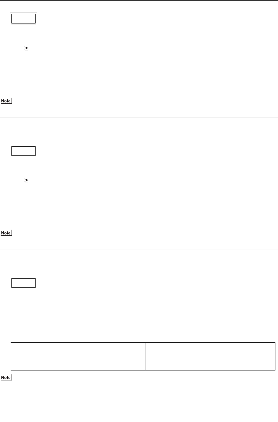
[ IX Troubleshooting ]
- 251 -
HWE09080 GB
1. Error Code
Abnormal bus voltage rise (Detail code 109)
2. Error definition and error detection method
If Vdc 400V is detected during inverter operation.
3. Cause, check method and remedy
(1) Different voltage connection
Check the power supply voltage on the power supply terminal block (TB1).
(2) INV board failure
If the problem recurs, replace the INV board.
In the case of 4220: INV board
Refer to section -6- "Inverter (THMU-A)" under part [4] Troubleshooting Principal Parts for error codes related to the
inverter.(page 328)
1. Error Code
Abnormal bus voltage rise (Detail code 109)
2. Error definition and error detection method
If Vdc 830V is detected during inverter operation.
3. Cause, check method and remedy
(1) Different voltage connection
Check the power supply voltage on the power supply terminal block (TB1).
(2) INV board failure
If the problem recurs, replace the INV board.
In the case of 4220: INV board
Refer to section -6- "Inverter (YHMU-A)" under part [4] Troubleshooting Principal Parts for error codes related to the
inverter.(page 333)
1. Error Code
Logic error (Detail code 111)
2. Error definition and error detection method
H/W error
If only the H/W error logic circuit operates, and no identifiable error is detected.
3. Cause, Check method and remedy
In the case of 4220
Refer to section -6- "Inverter (THMU-A)" under part [4] Troubleshooting Principal Parts for error codes related to the
inverter.(page 328)
4220 (THMU-A)
4220 (YHMU-A)
4220 (THMU-A)
Cause Check method and remedy
(1) External noise
(2) INV board failure Refer to IX [4] -6- (2) [1].
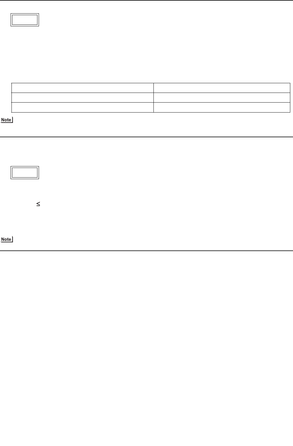
[ IX Troubleshooting ]
- 252 -
HWE09080 GB
1. Error Code
Logic error (Detail code 111)
2. Error definition and error detection method
H/W error
If only the H/W error logic circuit operates, and no identifiable error is detected.
3. Cause, Check method and remedy
In the case of 4220
Refer to section -6- "Inverter (YHMU-A)" under part [4] Troubleshooting Principal Parts for error codes related to the
inverter.(page 333)
1. Error Code
Low bus voltage at startup (Detail code 131)
2. Error definition and error detection method
When Vdc 160 V is detected just before the inverter operation.
3. Cause, check method and remedy
(1) Inverter main circuit failure
Same as detail code 108 of 4220 error
Refer to section -6- "Inverter" under part [4] Troubleshooting Principal Parts for error codes related to the inverter.
4220 (YHMU-A)
Cause Check method and remedy
(1) External noise
(2) INV board failure Refer to IX [4] -6- (2) [1].(page 335)
4220
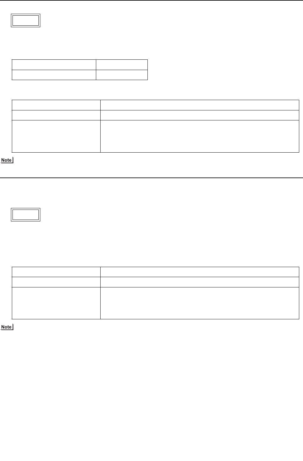
[ IX Troubleshooting ]
- 253 -
HWE09080 GB
1. Error Code
Heatsink overheat protection
2. Error definition and error detection method
When the heat sink temperature (THHS) remains at or above TOH is detected.
3. Cause, check method and remedy
Refer to section -6- "Inverter (THMU-A)" under part [4] Troubleshooting Principal Parts for error codes related to the
inverter.(page 328)
1. Error Code
Heatsink overheat protection
2. Error definition and error detection method
When the heat sink temperature (THHS) remains at or above 100°C [212°F] is detected.
3. Cause, check method and remedy
Refer to section -6- "Inverter (YHMU-A)" under part [4] Troubleshooting Principal Parts for error codes related to the
inverter.(page 333)
4230 (THMU-A)
Model TOH
P72, P96, P120 models 100°C [212°F]
Cause Check method and remedy
(1) Air passage blockage Check that the heat sink cooling air passage is not blocked
(2) THHS failure 1) Check for proper installation of the INV board IGBT. (Check for proper instal-
lation of the IGBT heatsink.)
2) Check for proper installation of the INV board IGBT.
->If an abnormal value appears, replace the INV board.
4230 (YHMU-A)
Cause Check method and remedy
(1) Air passage blockage Check that the heat sink cooling air passage is not blocked
(2) THHS failure 1) Check for proper installation of the INV board IGBT. (Check for proper instal-
lation of the IGBT heatsink.)
2) Check the THHS sensor reading on the LED monitor.
->If an abnormal value appears, replace the INV board.
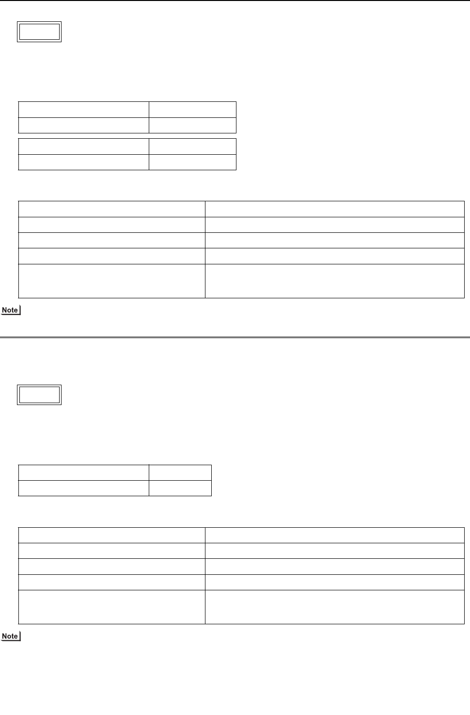
[ IX Troubleshooting ]
- 254 -
HWE09080 GB
1. Error Code
Overload protection
2. Error definition and error detection method
If the output current of "(Iac) >Imax (Arms)" or "THHS > TOL" is continuously detected for 10 minutes or more during inverter
operation.
3. Cause, check method and remedy
Refer to section -6- "Inverter (THMU-A)" under part [4] Troubleshooting Principal Parts for error codes related to the
inverter.(page 328)
1. Error Code
Overload protection
2. Error definition and error detection method
If the output current of "(Iac) >Imax (Arms)" or "THHS > 95°C [203°F] " is continuously detected for 10 minutes or more during
inverter operation.
3. Cause, check method and remedy
Refer to section -6- "Inverter (YHMU-A)" under part [4] Troubleshooting Principal Parts for error codes related to the
inverter.(page 333)
4240 (THMU-A)
Model Imax(Arms)
P72, P96, P120 models 35
Model TOL
P72, P96, P120 models 95°C [203°F]
Cause Check method and remedy
(1) Air passage blockage Check that the heat sink cooling air passage is not blocked
(2) Power supply environment Power supply voltage is 188 V or above.
(3) Inverter failure Refer to IX [4] -6-.(page 328)
(4) Compressor failure Check that the compressor has not overheated during operation.
-> Check the refrigerant circuit (oil return section).
Refer to IX [4] -6- (2) [2].(page 330)
4240 (YHMU-A)
Model Imax(Arms)
P72, P96, P120 models 19
Cause Check method and remedy
(1) Air passage blockage Check that the heat sink cooling air passage is not blocked
(2) Power supply environment Power supply voltage is 414 V or above.
(3) Inverter failure Refer to IX [4] -6-.(page 333)
(4) Compressor failure Check that the compressor has not overheated during operation.
-> Check the refrigerant circuit (oil return section).
Refer to IX [4] -6- (2) [2].(page 335)
[ IX Troubleshooting ]
- 255 -
HWE09080 GB
1. Error Code
IPM error (Detail code 101)
2. Error definition and error detection method
IPM error signal is detected.
3. Cause, check method and remedy
Refer to section -6- "Inverter (THMU-A)" under part [4] Troubleshooting Principal Parts for error codes related to the
inverter.(page 328)
1. Error Code
IPM error (Detail code 101)
2. Error definition and error detection method
IPM error signal is detected.
3. Cause, check method and remedy
Refer to section -6- "Inverter (YHMU-A)" under part [4] Troubleshooting Principal Parts for error codes related to the
inverter.(page 333)
4250 (THMU-A)
Cause Check method and remedy
(1) Inverter output related Refer to IX [4] -6- (2) [1]-[4].(page 330)
4250 (YHMU-A)
Cause Check method and remedy
(1) Inverter output related Refer to IX [4] -6- (2) [1]-[4].(page 335)
Check the IGBT module resistance value of the INV board, if no
problems are found.
(Refer to the Trouble shooting for IGBT module)
[ IX Troubleshooting ]
- 256 -
HWE09080 GB
1. Error Code
Instantaneous overcurrent (Detail code 106)
Overcurrent (Detail code 107)
2. Error definition and error detection method
Overcurrent 123 Apeak or 42 Arms and above is detected by the current sensor.
3. Cause, check method and remedy
Refer to section -6- "Inverter (THMU-A)" under part [4] Troubleshooting Principal Parts for error codes related to the
inverter.(page 328)
1. Error Code
Instantaneous overcurrent (Detail code 106)
Overcurrent (Detail code 107)
2. Error definition and error detection method
Overcurrent 94 Apeak or 22 Arms and above is detected by the current sensor.
3. Cause, check method and remedy
Refer to section -6- "Inverter (YHMU-A)" under part [4] Troubleshooting Principal Parts for error codes related to the
inverter.(page 333)
4250 (THMU-A)
Cause Check method and remedy
(1) Inverter output related Refer to IX [4] -6- (2) [1]-[4].(page 330)
Check the IGBT module resistance value of the INV board if no
problems are found.
(Refer to "Troubleshooting" for IGBT module related problems)
4250 (YHMU-A)
Cause Check method and remedy
(1) Inverter output related Refer to IX [4] -6- (2) [1]-[4].(page 335)
Check the IGBT module resistance value of the INV board if no
problems are found.
(Refer to "Troubleshooting" for IGBT module related problems)

[ IX Troubleshooting ]
- 257 -
HWE09080 GB
1. Error Code
Short-circuited IPM/Ground fault (Detail code 104)
2. Error definition and error detection method
When IPM/IGBT short damage or grounding on the load side is detected just before starting the inverter.
3. Cause, check method and remedy
Refer to section -6- "Inverter" under part [4] Troubleshooting Principal Parts for error codes related to the inverter.
4250
Cause Check method and remedy
(1) Grounding fault compressor Refer to IX [4] -6- (2) [2].
(2) Inverter output related Refer to IX [4] -6- (2) [1]-[4].

[ IX Troubleshooting ]
- 258 -
HWE09080 GB
1. Error Code
Overcurrent error due to short-circuited motor (Detail code 105)
2. Error definition and error detection method
When a short is detected on the load side just before starting the inverter operation.
3. Cause, Check method and remedy
Refer to section -6- "Inverter" under part [4] Troubleshooting Principal Parts for error codes related to the inverter.
1. Error Code
Heatsink overheat protection at startup
2. Error definition and error detection method
The heatsink temperature (THHS) remains at or above TOH for 10 minutes or more at inverter startup.
3. Cause, check method and remedy
Same as 4230 error
1. Error Code
Heatsink overheat protection at startup
2. Error definition and error detection method
The heatsink temperature (THHS) remains at or above 100°C [212°F] for 10 minutes or more at inverter startup.
3. Cause, check method and remedy
Same as 4230 error
4250
Cause Check method and remedy
(1) Short - circuited compressor Refer to IX [4] -6- (2) [2].
(2) Output wiring Check for a short circuit.
4260 (THMU-A)
Model TOH
P72, P96, P120 models 100°C [212°F]
4260 (YHMU-A)

[ IX Troubleshooting ]
- 259 -
HWE09080 GB
1. Error Code
Return air temperature sensor (TH21) fault (Indoor unit)
Return air temperature sensor (TH4) fault (OA processing unit)
Pipe temperature sensor (TH22) fault (Indoor unit)
Pipe temperature sensor (TH2) fault (OA processing unit)
Gas-side pipe temperature sensor (TH23) fault (Indoor unit)
Gas-side pipe temperature sensor (TH3) fault (OA processing unit)
Intake air temperature sensor (TH1) fault (OA processing unit)
Intake air temperature sensor (TH24) fault (All-fresh (100% outdoor air) type indoor unit)
2. Error definition and error detection method
If a short or an open is detected during thermostat ON, the heat source unit turns to anti-restart mode for 3 minutes. When
the error is not restored after 3 minutes (if restored, the heat source unit runs normally), the heat source unit makes an error
stop.
Short: detectable at 90°C [194°F] or higher
Open: detectable at -40°C [-40°F] or lower
Sensor error at gas-side cannot be detected under the following conditions.
During heating operation
During cooling operation for 3 minutes after the compressor turns on.
3. Cause, check method and remedy
5101
5102
5103
5104
Cause Check method and remedy
(1) Thermistor failure Check the thermistor resistor.
0°C [32°F]: 15 kohm
10°C [50°F]: 9.7 kohm
20°C [68°F] : 6.4 kohm
30°C [86°F] : 4.3 kohm
40°C [104°F] : 3.1 kohm
(2) Connector contact failure
(3) Disconnected wire or partial disconnected
thermistor wire
(4) Unattached thermistor or contact failure
(5) Indoor board (detection circuit) failure Check the connector contact.
When no fault is found, the indoor board is a failure.
[ IX Troubleshooting ]
- 260 -
HWE09080 GB
1. Error Code
HIC bypass circuit outlet temperature sensor (TH2) fault (Heat source unit)
Heat exchanger outlet temperature sensor (TH3) fault (Heat source unit)
Discharge temperature sensor (TH4) fault (Heat source unit)
Accumulator inlet temperature sensor (TH5) fault (Heat source unit)
HIC circuit outlet temperature sensor (TH6) fault (Heat source unit)
Outside temperature sensor (TH7) fault (Heat source unit)
2. Error definition and error detection method
When a short (high temperature intake) or an open (low temperature intake) of the thermistor is detected (the first detection),
the heat source unit stops, turns to anti-restart mode for 3 minutes, and restarts when the detected temperature of the therm-
istor.
When a short or an open is detected again (the second detection) after the first restart of the heat source unit, the heat source
unit stops, turns to anti-restart mode for 3 minutes, and restarts in 3 minutes when the detected temperature is within the nor-
mal range.
When a short or an open is detected again (the third detection) after the previous restart of the heat source unit, the heat
source unit makes an error stop.
When a short or an open of the thermistor is detected just before the restart of the heat source unit, the heat source unit makes
an error stop, and the error code "5102", "5103", 5104", "5105", "5106"or "5107" will appear.
During 3-minute antirestart mode, preliminary errors will be displayed on the LED display.
A short or an open described above is not detected for 10 minutes after the compressor start, during defrost mode, or for 3
minutes after defrost mode.
3. Cause, check method and remedy
<Reference>
5102
5103
5104
5105
5106
5107
Cause Check method and remedy
(1) Thermistor failure Check thermistor resistance.
(2) Pinched lead wire Check for pinched lead wire.
(3) Torn wire coating Check for wire coating.
(4) A pin on the male connector is missing or
contact failure
Check connector.
(5) Disconnected wire Check for wire.
(6) Thermistor input circuit failure on the control
board
Check the intake temperature of the sensor with the LED
monitor.
When the temperature is far different from the actual temper-
ature, replace the control board.
TH2
TH3
TH4
TH5
TH6
TH7
Open detection
-40 C [ -40 F ] and below (130 k )
-40 C [ -40 F ] and below (130 k )
0 C [ 32 F ] and below (698 k )
-40 C [ -40 F ] and below (130 k )
-40 C [ -40 F ] and below (130 k )
-40 C [ -40 F ] and below (130 k )
Short detection
70 C [158 F ] and above (0.4 k )
110 C [230 F ] and above (0.4 k )
240 C [464 F ] and above (0.57 k )
70 C [158 F ] and above (0.4 k )
70 C [158 F ] and above (1.14 k )
110 C [230 F ] and above (0.4 k )

[ IX Troubleshooting ]
- 261 -
HWE09080 GB
1. Error Code
Heatsink temperature sensor (THHS) fault (Detail code 01)
2. Error definition and error detection method
When a short or an open of THHS is detected just before or during the inverter operation.
3. Cause, check method and remedy
Refer to section -6- "Inverter " under part [4] Troubleshooting Principal Parts for error codes related to the inverter.
5110
Cause Check method and remedy
(1) INV board failure If the problem recurs when the unit is put into operation, replace
the INV board.
[ IX Troubleshooting ]
- 262 -
HWE09080 GB
1. Error Code
High-pressure sensor fault (63HS1)
2. Error definition and error detection method
If the high pressure sensor detects 0.098MPa [14psi] or less during the operation, the heat source unit stops once, turns to
anti-restart mode for 3 minutes, and restarts after 3 minutes when the detected high pressure sensor is 0.098MPa [14psi] or
more.
If the high pressure sensor detects 0.098MPa [14psi] or less just before the restart, the heat source unit makes an error stop,
and the error code "5201" will appear.
During 3-minute antirestart mode, preliminary errors will be displayed on the LED display.
A error is not detected for 3 minutes after the compressor start.
3. Cause, check method and remedy
5201
Cause Check method and remedy
(1) High pressure sensor failure Refer to the page on the troubleshooting of
the high pressure sensor.
(IX [4] -1- (page 306))
(2) Pressure drop due to refrigerant leak
(3) Torn wire coating
(4) A pin on the male connector is missing or contact failure
(5) Disconnected wire
(6) High pressure sensor input circuit failure on the control board
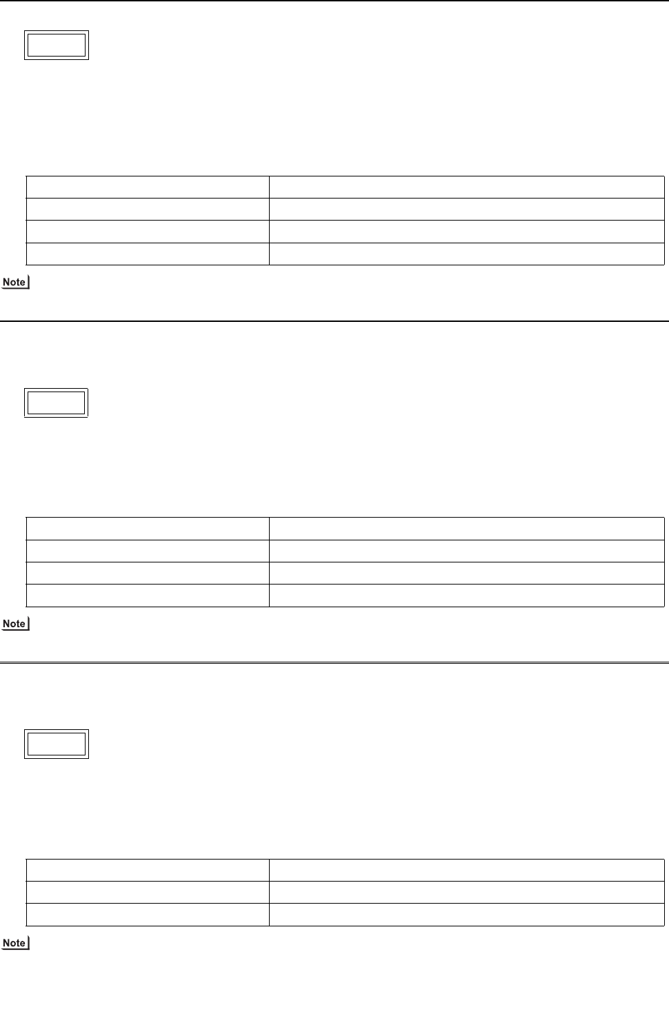
[ IX Troubleshooting ]
- 263 -
HWE09080 GB
1. Error Code
ACCT sensor fault (Detail code 115)
2. Error definition and error detection method
When the formula "output current < 2 Arms" remains satisfied for 10 seconds while the inverter is in operation.
3. Cause, check method and remedy
P72 and P96 models
Refer to section -6-"Inverter (THMU-A)" under part [4] Troubleshooting Principal Parts for error codes related to the
inverter.(page 328)
1. Error Code
ACCT sensor fault (Detail code 115)
2. Error definition and error detection method
When the formula "output current < 1.5 Arms" remains satisfied for 10 seconds while the inverter is in operation.
3. Cause, check method and remedy
Refer to section -6-"Inverter (YHMU-A)" under part [4] Troubleshooting Principal Parts for error codes related to the
inverter.(page 333)
1. Error Code
ACCT sensor circuit fault (Detail code 117)
2. Error definition and error detection method
When an error value is detected with the ACCT detection circuit just before the inverter starts
3. Cause, check method and remedy
Refer to section -6-"Inverter" under part [4] Troubleshooting Principal Parts for error codes related to the inverter.
5301 (THMU-A)
Cause Check method and remedy
(1) Inverter open output phase Check the output wiring connections.
(2) Compressor failure Refer to IX [4] -6- (2) [2].(page 330)
(3) INV board failure Refer to IX [4] -6- (2) [1], [3], [4].(page 330)
5301 (YHMU-A)
Cause Check method and remedy
(1) Inverter open output phase Check the output wiring connections.
(2) Compressor failure Refer to IX [4] -6- (2) [2].
(3) INV board failure Refer to IX [4] -6- (2) [1], [3], [4].
5301
Cause Check method and remedy
(1) INV board failure Refer to IX [4] -6- (2) [1], [3], [4].
(2) Compressor failure Refer to IX [4] -6- (2) [2].
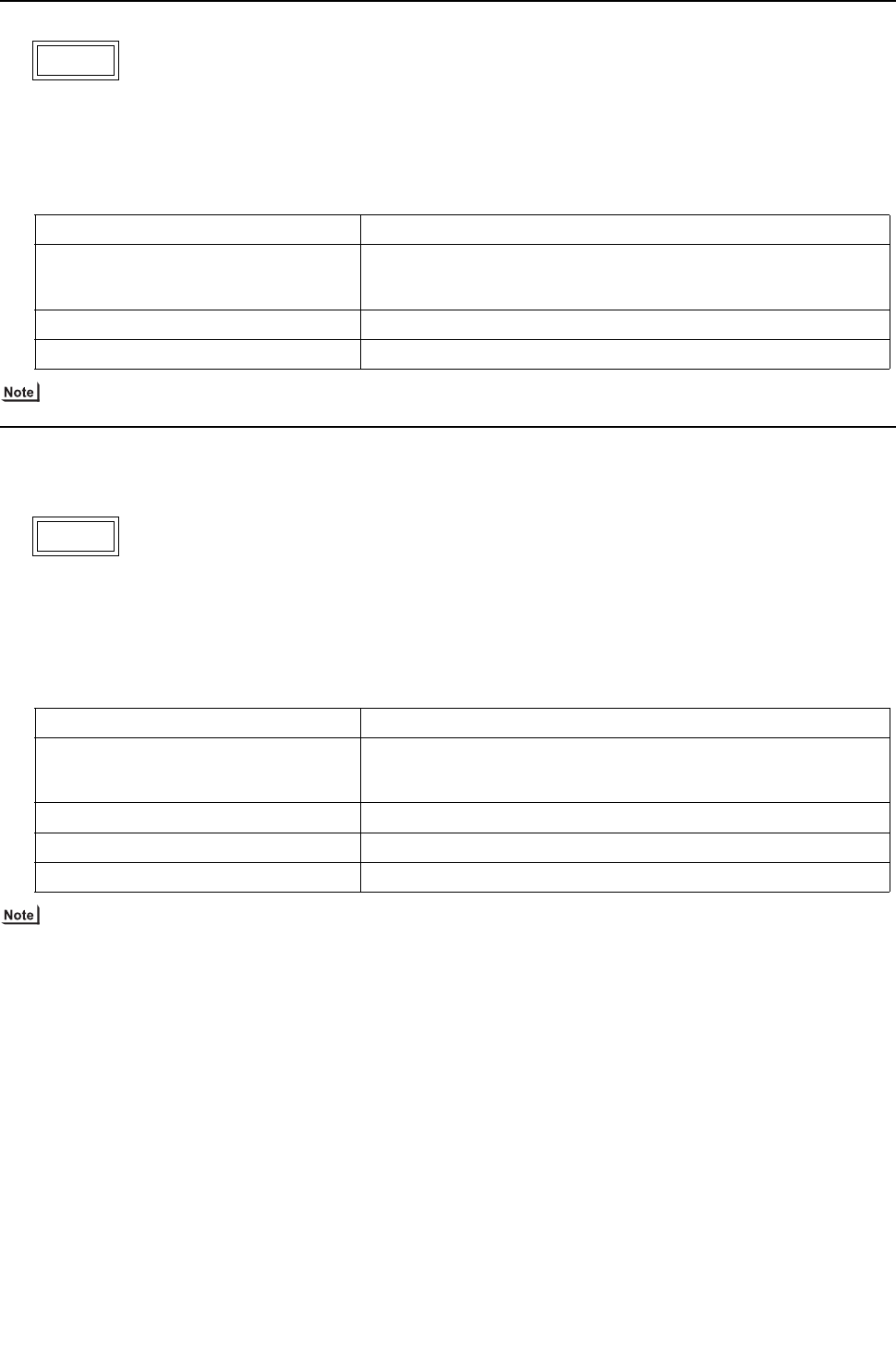
[ IX Troubleshooting ]
- 264 -
HWE09080 GB
1. Error Code
Open-circuited IPM/Loose ACCT connector (Detail code 119)
2. Error definition and error detection method
Presence of enough current cannot be detected during the self-diagnostic operation immediately before inverter startup.
3. Cause, check method and remedy
Refer to section -6- "Inverter" under part [4] Troubleshooting Principal Parts for error codes related to the inverter.
1. Error Code
Faulty ACCT wiring (Detail code 120)
2. Error definition and error detection method
Presence of target current cannot be detected during the self-diagnostic operation immediately before startup. (Detection of
improperly mounted ACCT sensor)
3. Cause, check method and remedy
Refer to section -6- "Inverter" under part [4] Troubleshooting Principal Parts for error codes related to the inverter.
5301
Cause Check method and remedy
(1) Inverter output wiring problem Check output wiring connections.
Confirm that the U- and W-phase output cables are put through CT12
and CT22 on the INV board respectively.
(2) Inverter failure Refer to IX [4] -6-.
(3) Compressor failure Refer to IX [4] -6- (2) [2].
(4) INV board failure Replace the INV board.

[ IX Troubleshooting ]
- 265 -
HWE09080 GB
1. Error Code
Loose float switch connector
2. Error definition and error detection method
Detection of the disconnected float switch (open-phase condition) during operation
3. Cause, check method and remedy
(1) CN4F disconnection or contact failure
Check for disconnection of the connector (CN4F) on the indoor unit control board.
1. Error Code
Remote controller board fault (nonvolatile memory error)
2. Error definition and error detection method
This error is detected when the data cannot be read out from the built-in nonvolatile memory on the remote controller.
3. Cause, check method and remedy
(1) Remote controller failure
Replace the remote controller.
1. Error Code
Remote controller board fault (clock IC error)
2. Error definition and error detection method
This error is detected when the built-in clock on the remote controller is not properly functioning.
3. Cause, check method and remedy
(1) Remote controller failure
Replace the remote controller.
5701
6201
6202
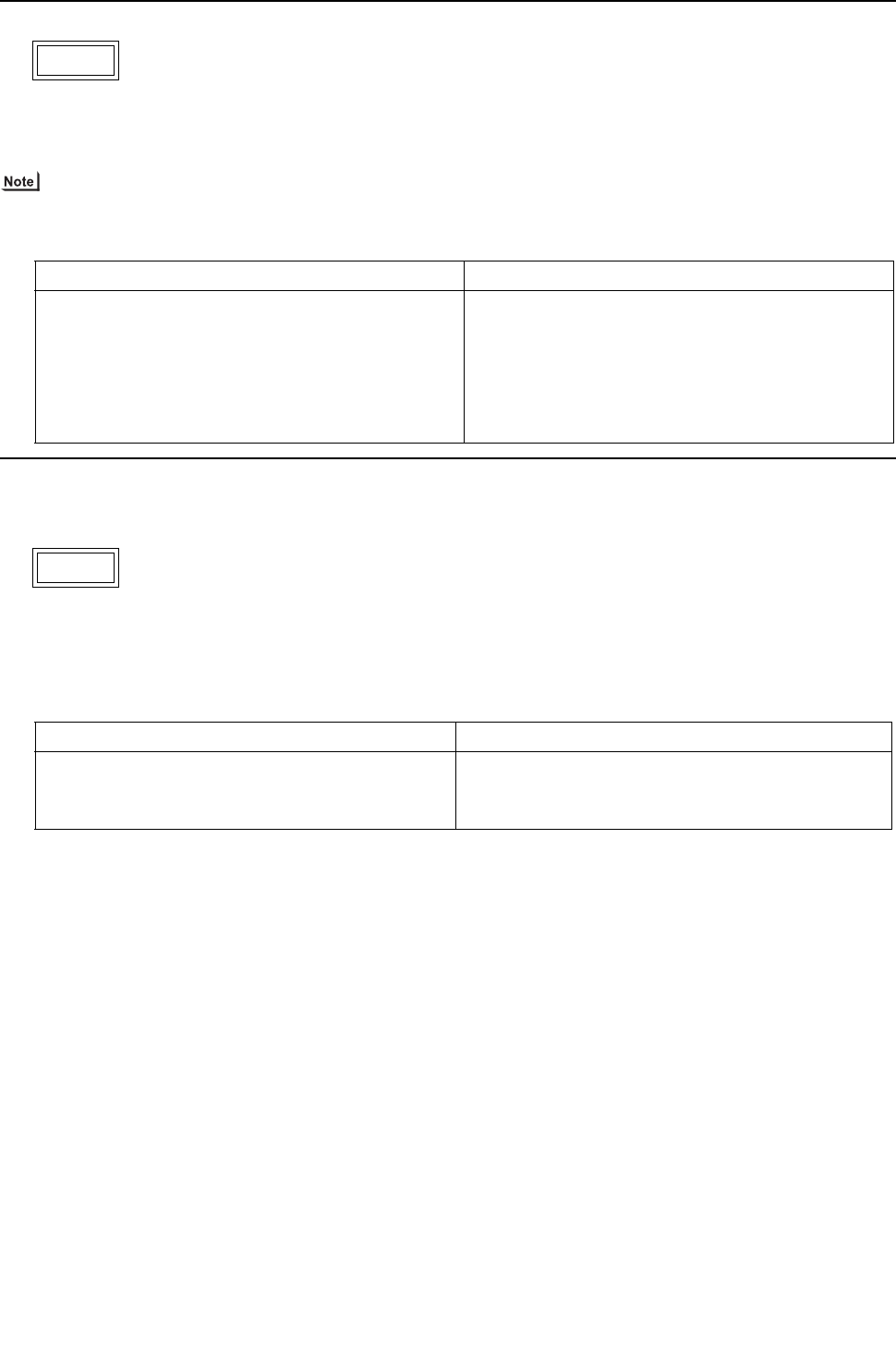
[ IX Troubleshooting ]
- 266 -
HWE09080 GB
1. Error Code
Address overlaps
2. Error definition and error detection method
An error in which signals from more than one indoor units with the same address are received
The address and attribute that appear on the remote controller indicate the controller that detected the error.
3. Cause, check method and remedy
1. Error Code
Polarity setting error
2. Error definition and error detection method
The error detected when transmission processor cannot distinguish the polarities of the M-NET transmission line.
3. Cause, check method and remedy
6600
Cause Check method and remedy
Two or more of the following have the same address:
Heat source units, indoor units, LOSSNAY units, con-
trollers such as M-NET remote controllers.
<Example>
6600 "01" appears on the remote controller
Unit #01 detected the error.
Two or more units in the system have 01 as their ad-
dress.
Find the unit that has the same address as that of the
error source.
Once the unit is found, correct the address. Then,
turn off the heat source units, indoor units, and
LOSSNAY units, keep them all turned off for at least
five minutes, and turn them back on.
6601
Cause Check method and remedy
(1) No voltage is applied to the M-NET transmission
line.
Check if power is supplied to the M-NET transmission
line and correct any problem found.
(2) M-NET transmission line is short-circuited.
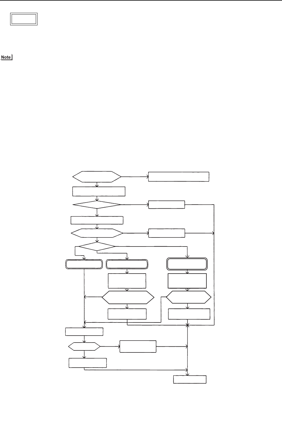
[ IX Troubleshooting ]
- 267 -
HWE09080 GB
1. Error Code
Transmission processor hardware error
2. Error definition and error detection method
Although "0" was surely transmitted by the transmission processor, "1" is displayed on the transmission line.
The address/attribute appeared on the display on the remote controller indicates the controller where an error oc-
curred.
3. Cause
1) When the wiring work of or the polarity of either the indoor or heat source transmission line is performed or is changed while
the power is on, the transmitted data will collide, the wave shape will be changed, and an error will be detected.
2) Grounding fault of the transmission line
3) When grouping the indoor units that are connected to different heat source units, the male power supply connectors on the
multiple heat source units are connected to the female power supply switch connector (CN40).
4) When the power supply unit for transmission lines is used in the system connected with MELANS, the male power supply
connector is connected to the female power supply switch connector (CN40) on the heat source unit.
5) Controller failure of the source of the error
6) When the transmission data is changed due to the noise on the transmission line
7) Voltage is not applied on the transmission line for centralized control (in case of grouped indoor units connected to different
heat source units or in case of the system connected with MELANS)
4. Check method and remedy
6602
NO
Tightly reconnect the male power
supply connector to the female
power supply switch connector (CN40).
YES
YES
YES
YES
YES
YES
NO
NO
NO
NO
Is the transmission line work
performed while the power is on?
Check the power source of the indoor unit.
198 / 264V?
Check the transmission line work is performed
and the shielded wire is treated properly.
Grounding fault or does the shielded
wire contact with the transmission line?
System ?
Faulty power source work
Improper transmission line work
Turn off the power source of heat source-
indoor units, and turn them on again.
NO
Investigation into the
transmission line noise
Noise exist?
Controller failure of the
source of the error
*For the investigation method, follow
<Investigation method of transmission wave shape/noise>
Investigation into the
cause of the noise
Correct the error.
System with the power supply
unit for transmission lines
Is the male power supply connector
connected to the female power supply
switch connector (CN40) on only one
of the heat source unit?
Is the male power supply connector
connected to the female power supply
switch connector (CN40) ?
Confirm that the power supply
connector on the heat source
unit is not plugged into CN40.
Confirm that the power supply
connector on the heat source
unit is not plugged into CN40.
Disconnect the male
power supply on
CN40 and connect it to CN41
Single-heat source-unit
system
Multiple-heat source-unit
system
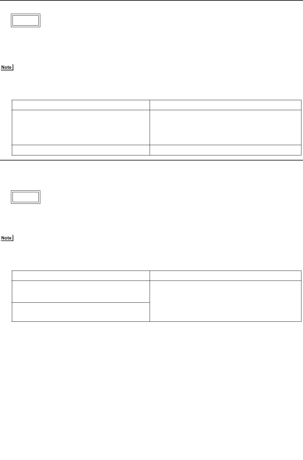
[ IX Troubleshooting ]
- 268 -
HWE09080 GB
1. Error Code
Transmission line bus busy error
2. Error definition and error detection method
Generated error when the command cannot be transmitted for 4-10 minutes in a row due to bus-busy
Generated error when the command cannot be transmitted to the transmission line for 4-10 minutes in a row due to noise
The address/attribute appeared on the display on the remote controller indicates the controller where an error oc-
curred.
3. Cause, check method and remedy
1. Error Code
Communication error between device and transmission processors
2. Error definition and error detection method
Communication error between the main microcomputer on the indoor unit board and the microcomputer for transmission
The address/attribute appeared on the display on the remote controller indicates the controller where an error oc-
curred.
3. Cause, check method and remedy
6603
Cause Check method and remedy
(1) The transmission processor cannot be transmit-
ted as the short-wavelength voltage like noise ex-
ists consecutively on the transmission line.
No noise indicates that the error source controller is a fail-
ure. If noise exists, investigate the noise.
-> No noise indicates that the error source controller is a
failure.
-> If noise exists, investigate the noise.
(2) Error source controller failure
6606
Cause Check method and remedy
(1) Data is not properly transmitted due to accidental
erroneous operation of the controller of the error
source.
Turn off the power source of the heat source and the in-
door units.(When the power source is turned off separate-
ly, the microcomputer will not be reset, and the error will
not be corrected.)
-> If the same error occurs, the error source controller is
a failure.
(2) Error source controller failure

[ IX Troubleshooting ]
- 269 -
HWE09080 GB
1. Error Code
No ACK error
2. Error definition and error detection method
The error is detected when no acknowledgement (ACK signal) is received after the transmission. (eg. When the data is trans-
mitted six times in a row with 30 seconds interval, the error is detected on the transmission side.)
The address/attribute appeared on the display on the remote controller indicates the controller which did not provide
the response (ACK).
3. System configuration
(1) System with one heat source unit
6607
Error
source
address
Error dis-
play
Detection
method Cause Check method and remedy
Heat
source
unit (OC)
ME re-
mote con-
troller
(RC)
MA re-
mote con-
troller
(MA)
No ac-
knowl-
edgement
(ACK) at
IC trans-
mission to
OC
(1) Contact failure of transmission line of OC or IC Turn off the power
source of the heat
source unit, and turn it
on again.
If the error is accidental,
it will run normally. If not,
check the causes (1) -
(4).
(2) Decrease of transmission line voltage/signal by ex-
ceeding acceptable range of transmission wiring.
Farthest:200 m [656ft] or less
Remote controller wiring:
10m [32ft] or less
(3) Erroneous sizing of transmission line (Not within the
range below). Wire diameter:
1.25mm2 [AWG16] or more
(4) Heat source unit control board failure
BC con-
troller
(BC)
ME re-
mote con-
troller
(RC)
MA re-
mote con-
troller
(MA)
No ac-
knowl-
edgement
(ACK) at
IC trans-
mission to
BC
(1) When BC controller address is changed or modified
during operation.
Turn off the heat source-
indoor units for 5 or
more minutes, and turn
them on again.
If the error is accidental,
they will run normally. If
not, check the causes
(1) - (4).
(2) Faulty or disconnected transmission wiring of BC
controller
(3) Disconnected connector of BC controller (CN02)
(4) Faulty control board of BC controller
Indoor
unit (IC)
ME re-
mote con-
troller
(RC)
MA re-
mote con-
troller
(MA)
No ac-
knowl-
edgement
(ACK) at
RC trans-
mission to
IC
(1) When IC unit address is changed or modified during
operation.
Turn off the heat source-
indoor units for 5 or
more minutes, and turn
them on again.
If the error is accidental,
they will run normally.
If not, check the causes
(1) - (5).
(2) Faulty or disconnected IC transmission wiring
(3) Disconnected IC connector
(CN2M)
(4) Indoor unit controller failure
(5) ME remote controller failure
LOSS-
NAY
(LC)
ME re-
mote con-
troller
(RC)
MA re-
mote con-
troller
(MA)
No ac-
knowl-
edgement
(ACK) at
IC trans-
mission to
LC
(1) The power source of LOSSNAY has been shut off. Turn off the power
source of LOSSNAY
and turn it on again.
If the error is accidental,
it will run normally.
If not, check the causes
(1) - (5).
(2) When the address of LOSSNAY is changed in the
middle of the operation
(3) Faulty or disconnected transmission wiring of
LOSSNAY
(4) Disconnected connector (CN1) on LOSSNAY
(5) Controller failure of LOSSNAY
ME re-
mote
control-
ler (RC)
ME re-
mote con-
troller
(RC)
MA re-
mote con-
troller
(MA)
No ac-
knowl-
edgement
(ACK) at
IC trans-
mission to
RC
(1) Faulty transmission wiring at IC unit side. Turn off the power
source of the heat
source unit for 5 minutes
or more, and turn it on
again.
If the error is accidental,
it will run normally.
If not, check the causes
(1) - (4).
(2) Faulty wiring of the transmission line for ME remote
controller
(3) When the address of ME remote controller is
changed in the middle of the operation
(4) ME remote controller failure

[ IX Troubleshooting ]
- 270 -
HWE09080 GB
1. Error Code
No ACK error
2. Error definition and error detection method
The error is detected when no acknowledgement (ACK signal) is received after the transmission. (eg. When the data is trans-
mitted six times in a row with 30 seconds interval, the error is detected on the transmission side.)
The address/attribute appeared on the display on the remote controller indicates the controller which did not provide
the response (ACK).
3. System configuration
(2) Grouping of units in a system with multiple heat source units
6607
Error
source
address
Error display Detection
method Cause Check method and remedy
Heat
source
unit
(OC)
ME remote
controller (RC)
MA remote
controller (MA)
No acknowl-
edgement
(ACK) at IC
transmission to
OC
Same cause as that for system
with one heat source unit
Same remedy as that for sys-
tem with one heat source unit
BC con-
troller
(BC)
ME remote
controller
(RC)
MA remote
controller
(MA)
No acknowl-
edgement
(ACK) at IC
transmission to
BC
Same cause as that for system
with one heat source unit
Same remedy as that for sys-
tem with one heat source unit
Indoor
unit
(IC)
ME remote
controller (RC)
MA remote
controller (MA)
No acknowl-
edgement
(ACK) at RC
transmission to
IC
(1) Same causes as (1) - (5) for sys-
tem with one heat source unit
1) Turn off the power sources of
the heat source and indoor
units for 5 or more minutes,
and turn them on again. If the
error is accidental, the will run
normally.If not, check the
cause 2).
(2) Disconnection or short circuit of
the transmission line for the heat
source unit on the terminal block
for centralized control line con-
nection (TB7)
2) Check the causes of (1) - (5). If
the cause is found, correct it. If
no cause is found, check 3).
(3) When multiple heat source units
are connected and the power
source of one of the heat source
units has been shut off.
3) Check the LED displays for
troubleshooting on other re-
mote controllers whether an
error occurs.
(4) The male power supply connector
of the heat source unit is not con-
nected to the female power supply
switch connector (CN40).
If an error is found,
-> If an error is found, check
the check code definition, and
correct the error.
If no error is found,
-> Indoor unit board failure
(5) The male power supply connec-
tors on 2 or more heat source
units are connected to the female
power supply switch connector
(CN40) for centralized control.
If an error occurs, after the unit
runs normally once, the following
causes may be considered.
Total capacity error (7100)
Capacity code error (7101)
Error in the number of con-
nected units (7102)
Address setting error (7105)

[ IX Troubleshooting ]
- 271 -
HWE09080 GB
1. Error Code
No ACK error
2. Error definition and error detection method
The error is detected when no acknowledgement (ACK signal) is received after the transmission. (eg. When the data is trans-
mitted six times in a row with 30 seconds interval, the error is detected on the transmission side.)
The address/attribute appeared on the display on the remote controller indicates the controller which did not provide
the response (ACK).
3. System configuration
(2) Grouping of units in a system with multiple heat source units
6607
Error
source
address
Error display Detection
method Cause Check method and remedy
LOSS-
NAY
(LC)
ME remote
controller (RC)
MA remote
controller (MA)
No acknowl-
edgement
(ACK) at IC
transmission to
LC
(1) Factors (1) through (5) in the
"Factors in system with one
heat source unit" (When per-
forming an interlocked opera-
tion of the LOSSNAY unit
and the indoor units that are
connected to different heat
source units.)
1) Turn off the power source of
heat source unit for 5 or more
minutes, and turn it on again. If
the error is accidental, it will
run normally.If not, check the
cause 2).
(2) Disconnection or short circuit
of the transmission line for
the heat source unit on the
terminal block for centralized
control line connection (TB7)
2) Check the causes of (1) - (5). If
the cause is found, correct it. If
no cause is found, check 3).
(3) When multiple heat source
units are connected and the
power source of one of the
heat source units has been
shut off.
3) Same cause as that for indoor
unit described in 3)
(4) The male power supply con-
nector of the heat source unit
is not connected to the fe-
male power supply switch
connector (CN40).
(5) The male power supply con-
nectors on 2 or more heat
source units are connected to
the female power supply
switch connector (CN40) for
centralized control.
If an error occurs, after the
unit runs normally once, the
following causes may be con-
sidered.
Total capacity error
(7100)
Capacity code error
(7101)
Error in the number of
connected units (7102)
Address setting error
(7105)

[ IX Troubleshooting ]
- 272 -
HWE09080 GB
1. Error Code
No ACK error
2. Error definition and error detection method
The error is detected when no acknowledgement (ACK signal) is received after the transmission. (eg. When the data is trans-
mitted six times in a row with 30 seconds interval, the error is detected on the transmission side.)
The address/attribute appeared on the display on the remote controller indicates the controller which did not provide
the response (ACK).
3. System configuration
(2) Grouping of units in a system with multiple heat source units
6607
Error
source
address
Error display Detection
method Cause Check method and remedy
ME re-
mote con-
troller
(RC)
ME remote
controller (RC)
MA remote
controller (MA)
No acknowl-
edgement
(ACK) at IC
transmission to
RC
(1) Same causes as (1) - (4) for
system with one heat source
unit
1) Turn off the power source of
heat source unit for 5 or more
minutes, and turn it on again. If
the error is accidental, it will
run normally.If not, check the
cause 2).
(2) Disconnection or short circuit
of the transmission line for
the heat source unit on the
terminal block for centralized
control line connection (TB7)
2) Check the causes of (1) - (5). If
the cause is found, correct it. If
no cause is found, check 3).
(3) When multiple heat source
units are connected and the
power source of one of the
heat source units has been
shut off.
3) Same cause as that for indoor
unit described in 3)
(4) The male power supply con-
nector of the heat source unit
is not connected to the fe-
male power supply switch
connector (CN40).
(5) The male power supply con-
nectors on 2 or more heat
source units are connected to
the female power supply
switch connector (CN40) for
centralized control.
If the problem recurs after
normal operation is restored,
the problem is caused by one
of the following factors:
Total capacity error
(7100)
Capacity code setting
error (7101)
Error in the number of
connected units (7102)
Address setting error
(7105)
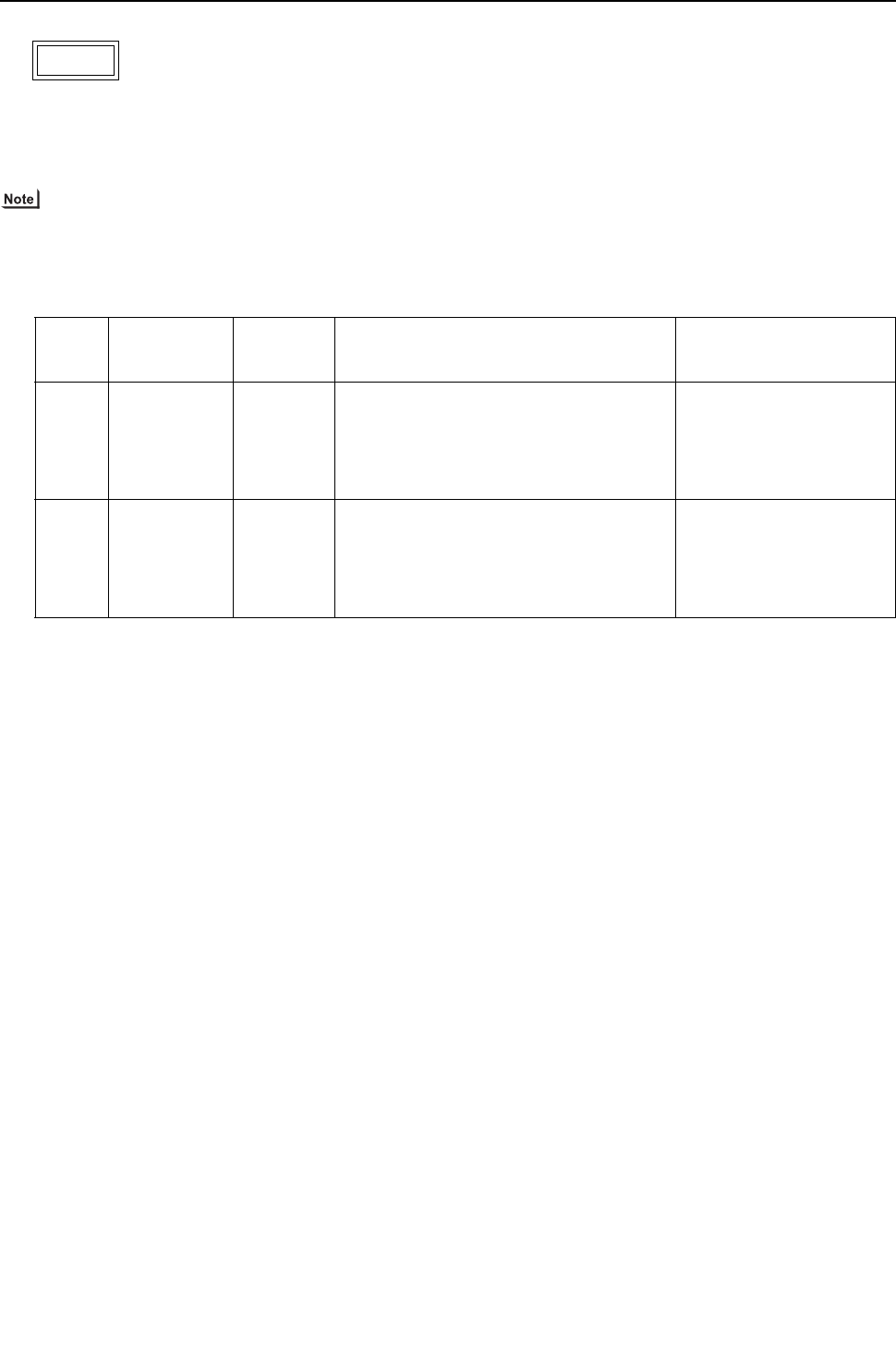
[ IX Troubleshooting ]
- 273 -
HWE09080 GB
1. Error Code
No ACK error
2. Error definition and error detection method
The error is detected when no acknowledgement (ACK signal) is received after the transmission. (eg. When the data is trans-
mitted six times in a row with 30 seconds interval, the error is detected on the transmission side.)
The address/attribute appeared on the display on the remote controller indicates the controller which did not provide
the response (ACK).
3. System configuration
(3) System connected to the system controllers (MELANS)
6607
Error
source
address
Error display Detection
method Cause Check method and remedy
Heat
source
unit
(OC)
ME remote
controller (RC)
System control-
ler (SC)
MA remote
controller (MA)
No acknowl-
edgement
(ACK) at IC
transmis-
sion to OC
Same cause as that for system with one
heat source unit
Same remedy as that for
system with one heat
source unit
BC con-
troller
(BC)
ME remote
controller (RC)
system control-
ler (SC)
MA remote
controller (MA)
No acknowl-
edgement
(ACK) at IC
transmis-
sion to BC
Same cause as that for system with one
heat source unit
Same remedy as that for
system with one heat
source unit

[ IX Troubleshooting ]
- 274 -
HWE09080 GB
1. Error Code
No ACK error
2. Error definition and error detection method
The error is detected when no acknowledgement (ACK signal) is received after the transmission. (eg. When the data is trans-
mitted six times in a row with 30 seconds interval, the error is detected on the transmission side.)
The address/attribute appeared on the display on the remote controller indicates the controller which did not provide
the response (ACK).
3. System configuration
(3) System connected to the system controllers (MELANS)
6607
Error
source
address
Error display Detection
method Cause Check method and remedy
Indoor
unit
(IC)
ME remote
controller (RC)
MA remote
controller (MA)
No acknowl-
edgement
(ACK) at RC
transmis-
sion to IC
Same as grouping of units in a system
with multiple heat source units
Same remedy as that for
grouping of units in a sys-
tem with multiple heat
source units
System control-
ler (SC)
No acknowl-
edgement
(ACK) at SC
transmis-
sion to IC
1. Error occurrence on some IC Same remedy as that for
system with one heat
source unit
(1) Same cause as that for system with one
heat source unit
2. Error occurrence on all IC in the system
with one heat source unit
1) Check the LED display
for troubleshooting on the
heat source unit.
(1) Total capacity error (7100) If an error is found,
check the check code
definition, and correct
the error.
If no error is found,
check 2).
(2) Capacity code error (7101)
(3) Error in the number of connected units
(7102)
(4) Address setting error (7105)
(5) Disconnection or short circuit of the trans-
mission line for the heat source unit on
the terminal block for centralized control
line connection (TB7)
2) Check (5) - (7) on the left.
(6) Turn off the power source of the heat
source unit
(7) Malfunction of electrical system for the
heat source unit
3. Error occurrence on all IC Check voltage of the
transmission line for cen-
tralized control.
20V or more: Check (1)
and (2) on the left.
Less than 20V: Check
(3) on the left.
(1) Same causes as (1) - (7) described in 2.
(2) The male power supply connectors on 2
or more heat source units are connected
to the female power supply switch con-
nector (CN40) for the transmission line for
centralized control.
(3) Disconnection or shutdown of the power
source of the power supply unit for trans-
mission line
(4) System controller (MELANS) malfunction

[ IX Troubleshooting ]
- 275 -
HWE09080 GB
1. Error Code
No ACK error
2. Error definition and error detection method
The error is detected when no acknowledgement (ACK signal) is received after the transmission. (eg. When the data is trans-
mitted six times in a row with 30 seconds interval, the error is detected on the transmission side.)
The address/attribute appeared on the display on the remote controller indicates the controller which did not provide
the response (ACK).
3. System configuration
(3) System connected to the system controllers (MELANS)
6607
Error
source
address
Error display Detection
method Cause Check method and remedy
ME re-
mote con-
troller
(RC)
ME remote
controller (RC)
System con-
troller (SC)
MA remote
controller (MA)
No acknowl-
edgement
(ACK) at IC
transmission to
RC
Same as grouping of units in a sys-
tem with multiple heat source units
Same remedy as that for
grouping of units in a system
with multiple heat source
units
System con-
troller
(SC)
No acknowl-
edgement
(ACK) at
MELANS
transmission to
RC
1. Error occurrence on some IC Same remedy as that for
system with one heat source
unit
(1) Same cause as that for system
with one heat source unit
2. Error occurrence on all IC in the
system with one heat source unit
1) Check the LED display for
troubleshooting on the heat
source unit.
(1) An error is found by the heat
source unit.
Total capacity error (7100)
Capacity code error (7101)
Error in the number of connected
units (7102)
Address setting error (7105)
If an error is found, check
the check code definition,
and correct the error.
If no error is found, check
the cause 2).
(2) Disconnection or short circuit of the
transmission line for the heat
source unit on the terminal block
for centralized control line connec-
tion (TB7)
2) Check (2) - (4) on the left.
(3) Turn off the power source of the
heat source unit
(4) Malfunction of electrical system for
the heat source unit
3. Error occurrence on all IC Check (1) - (4) on the left.
(1) Same causes as (1) - (4) described
in 2.
(2) When the power supply unit for
transmission lines is used and the
male power supply connector is
connected to the female power
supply switch connector (CN40) for
the transmission line for central-
ized control
(3) Disconnection or shutdown of the
power source of the power supply
unit for transmission line
(4) System controller (MELANS) mal-
function

[ IX Troubleshooting ]
- 276 -
HWE09080 GB
1. Error Code
No ACK error
2. Error definition and error detection method
The error is detected when no acknowledgement (ACK signal) is received after the transmission. (eg. When the data is trans-
mitted six times in a row with 30 seconds interval, the error is detected on the transmission side.)
The address/attribute appeared on the display on the remote controller indicates the controller which did not provide
the response (ACK).
3. System configuration
(3) System connected to the system controllers (MELANS)
6607
Error
source
address
Error display Detection
method Cause Check method and remedy
System
controller
(SC)
ME remote
controller
(RC)
MA remote
controller
(MA)
No acknowl-
edgement
(ACK) at IC
transmission to
SC
1. Error display on some displays on
ME remote controllers
Check (1) - (3) on the left.
(1) Faulty wiring of the transmission
line for ME remote controller
(2) Disconnection or contact failure of
the transmission connector for ME
remote controller
(3) ME remote controller failure
2. Error occurrence on all IC in the
system with one heat source unit
1) Check the LED display for
troubleshooting on the heat
source unit.
(1) An error is found by the heat source
unit.
Total capacity error (7100)
Capacity code error (7101)
Error in the number of connected
units (7102)
Address setting error (7105)
If an error is found, check
the check code definition,
and correct the error.
If no error is found, check
the cause 2)
(2) Disconnection or short circuit of the
transmission line for the heat
source unit on the terminal block for
centralized control line connection
(TB7)
2) Check (2) - (4) on the left.
(3) Turn off the power source of the
heat source unit
(4) Malfunction of electrical system for
the heat source unit
3. Error display on all displays on ME
remote controllers
Check (1) - (4) on the left
(1) Same causes as (1) - (4) described
in 2.
(2) When the power supply unit for
transmission lines is used and the
male power supply connector is
connected to the female power sup-
ply switch connector (CN40) for the
transmission line for centralized
control
(3) Disconnection or shutdown of the
power source of the power supply
unit for transmission line
(4) System controller (MELANS) mal-
function

[ IX Troubleshooting ]
- 277 -
HWE09080 GB
1. Error Code
No ACK error
2. Error definition and error detection method
The error is detected when no acknowledgement (ACK signal) is received after the transmission. (eg. When the data is trans-
mitted six times in a row with 30 seconds interval, the error is detected on the transmission side.)
The address/attribute appeared on the display on the remote controller indicates the controller which did not provide
the response (ACK).
3. System configuration
(4) Errors that are not limited to a particular system
6607
Error
source ad-
dress
Error dis-
play
Detection
method Cause Check method and remedy
Address
which
should not
be existed
- - (1) Although the address of ME
remote controller has been
changed after the group is set
using ME remote controller,
the indoor unit is keeping the
memory of the previous ad-
dress. The same symptom will
appear for the registration with
SC.
Delete unnecessary informa-
tion of non-existing address
which some indoor units have.
Use either of the following two
methods for deletion.
(2) Although the address of
LOSSNAY has been changed
after the interlock registration
of LOSSNAY is made using
ME remote controller, the in-
door unit is keeping the mem-
ory of the previous address.
1) Address deletion by ME remote
controller
Delete unnecessary address in-
formation using the manual set-
ting function of ME remote
controller. Refer to this service
handbook "IV [2] Group Set-
tings and Interlock Settings via
the ME Remote Controller 1. (3)
Address deletion."(page 98)
2) Deletion of connection informa-
tion of the heat source unit by
the deleting switch
Note that this switch deletes
all the group information set
via ME remote controller and
all the interlock information
of LOSSNAY and the indoor
unit.
Turn off the power source of
the heat source unit, and wait
for 5 minutes.
Turn on the dip switch (SW2-
2) on the heat source unit
control board.
Turn on the power source of
the heat source unit, and wait
for 5 minutes.
Turn off the power source of
the heat source unit, and wait
for 5 minutes.
Turn off the dip switch (SW2-
2) on the heat source unit
control board.
Turn on the power source of
the heat source unit.

[ IX Troubleshooting ]
- 278 -
HWE09080 GB
1. Error Code
No response error
2. Error definition and error detection method
When no response command is returned although acknowledgement (ACK) is received after transmission, an error is detect-
ed.
When the data is transmitted 10 times in a row with 3 seconds interval, an error is detected on the transmission side.
The address/attribute appeared on the display on the remote controller indicates the controller where an error oc-
curred.
3. Cause
1) The transmission line work is performed while the power is on, the transmitted data will collide, and the wave shape will be
changed.
2) The transmission is sent and received repeatedly due to noise.
3) Decrease of transmission line voltage/signal by exceeding acceptable range of transmission wiring.
Farthest:200m [656ft] or less
Remote controller wiring:12m [39ft] or less
4) The transmission line voltage/signal is decreased due to erroneous sizing of transmission line.
Wire diameter: 1.25mm2[AWG16] or more
4. Check method and remedy
1) When an error occurs during commissioning, turn off the power sources for the heat source unit, indoor unit, BC controller,
and LOSSNAY for 5 or more minutes, and then turn them on again.
When they return to normal operation, the cause of the error is the transmission line work performed with the power on.
If an error occurs again, check the cause 2).
2) Check 3) and 4) above.
If the cause is found, correct it.
If no cause is found, check 3).
3) Check transmission wave shape/ noise on trans-mission line by following "IX [3] Investigation of Transmission Wave Shape/
Noise" (page 303).
Noise is the most possible cause of the error "6608".
6608

[ IX Troubleshooting ]
- 279 -
HWE09080 GB
1. Error Code
MA controller signal reception error (No signal reception)
2. Error definition and error detection method
Communication between the MA remote controller and the indoor unit is not done properly.
No proper data has been received for 3 minutes.
3. Cause
1) Contact failure of the remote controller lines of MA remote controller or the indoor unit.
2) All the remote controllers are set to SUB.
3) Failure to meet wiring regulations
Wire length
Wire size
Number of remote controllers
Number of indoor units
4) The remote controller is removed after the installation without turning the power source off.
5) Noise interference on the remote controller transmission lines
6) Faulty circuit that is on the indoor board and performs transmission/ reception of the signal from the remote controller
7) Problems with the circuit on the remote controller that sends or receives the signals from the remote controller
4. Check method and remedy
1) Check for disconnected or loose transmission lines for the indoor units or MA remote controllers.
2) Confirm that the power is supplied to the main power source and the remote controller line.
3) Confirm that MA remote controller's capacity limit is not exceeded.
4) Check the sub/main setting of the MA remote controllers.One of them must be set to MAIN.
5) Diagnose the remote controller (described in the remote controller installation manual).
[OK]: no problems with the remote controller (check the wiring regulations)
[NG]: Replace the MA remote controller.
[6832, 6833, ERC]: Due to noise interference <Go to 6)>
6) Check wave shape/noise on MA remote controller line by following "IX [3] Investigation of Transmission Wave Shape/
Noise".(page 303)
7) When no problems are found with items 1) through 6), replace the indoor unit board or the MA remote controller.
The following status can be confirmed on LED1 and 2 on the indoor unit board.
If LED1 is lit, the main power source of the indoor unit is turned on.
If LED2 is lit, the MA remote controller line is being powered.
6831

[ IX Troubleshooting ]
- 280 -
HWE09080 GB
1. Error Code
MA remote controller signal transmission error (Synchronization error)
2. Error definition and error detection method
MA remote controller and the indoor unit is not done properly.
Failure to detect opening in the transmission path and unable to send signals
Indoor unit : 3 minutes
Remote controller : 6 seconds
3. Cause
1) Contact failure of the remote controller lines of MA remote controller or the indoor unit
2) 2 or more remote controllers are set to MAIN
3) Overlapped indoor unit address
4) Noise interference on the remote controller lines
5) Failure to meet wiring regulations
Wire length
Wire size
Number of remote controllers
Number of indoor units
6) Problems with the circuit on the remote controller that sends or receives the signals from the remote controller
4. Check method and remedy
1) Check for disconnected or loose transmission lines for the indoor units or MA remote controllers.
2) Confirm that the power is supplied to the main power source and the remote controller line.
3) Confirm that MA remote controller's capacity limit is not exceeded.
4) Check the sub/main setting of the MA remote controllers.One of them must be set to MAIN.
5) Diagnose the remote controller (described in the remote controller installation manual).
[OK]: no problems with the remote controller (check the wiring regulations)
[NG]: Replace the MA remote controller.
[6832, 6833, ERC]: Due to noise interference <Go to 6)>
6) Check wave shape/noise on MA remote controller line by following "IX [3] Investigation of Transmission Wave Shape/
Noise".(page 303)
7) When no problems are found with items 1) through 6), replace the indoor unit board or the MA remote controller.
The following status can be confirmed on LED1 and 2 on the indoor unit board.
If LED1 is lit, the main power source of the indoor unit is turned on.
If LED2 is lit, the MA remote controller line is being powered.
6832

[ IX Troubleshooting ]
- 281 -
HWE09080 GB
1. Error Code
MA remote controller signal transmission error (Hardware error)
2. Error definition and error detection method
Communication between the MA remote controller and the indoor unit is not done properly.
An error occurs when the transmitted data and the received data differ for 30 times in a row.
3. Cause
1) Contact failure of the remote controller lines of MA remote controller or the indoor unit
2) 2 or more remote controllers are set to MAIN
3) Overlapped indoor unit address
4) Noise interference on the remote controller lines
5) Failure to meet wiring regulations
Wire length
Wire size
Number of remote controllers
Number of indoor units
6) Problems with the circuit on the remote controller that sends or receives the signals from the remote controller
4. Check method and remedy
1) Check for disconnected or loose transmission lines for the indoor units or MA remote controllers.
2) Confirm that the power is supplied to the main power source and the remote controller line.
3) Confirm that MA remote controller's capacity limit is not exceeded.
4) Check the sub/main setting of the MA remote controllers.One of them must be set to MAIN.
5) Diagnose the remote controller (described in the remote controller installation manual).
[OK]: no problems with the remote controller (check the wiring regulations)
[NG]: Replace the MA remote controller.
[6832, 6833, ERC]: Due to noise interference <Go to 6)>
6) Check wave shape/noise on MA remote controller line by following "IX [3] Investigation of Transmission Wave Shape/
Noise".(page 303)
7) When no problems are found with items 1) through 6), replace the indoor unit board or the MA remote controller.
The following status can be confirmed on LED1 and 2 on the indoor unit board.
If LED1 is lit, the main power source of the indoor unit is turned on.
If LED2 is lit, the MA remote controller line is being powered.
6833

[ IX Troubleshooting ]
- 282 -
HWE09080 GB
1. Error Code
MA controller signal reception error (Start bit detection error)
2. Error definition and error detection method
Communication between the MA remote controller and the indoor unit is not done properly.
No proper data has been received for 2 minutes.
3. Cause
1) Contact failure of the remote controller lines of MA remote controller or the indoor unit.
2) All the remote controllers are set to SUB.
3) Failure to meet wiring regulations
Wire length
Wire size
Number of remote controllers
Number of indoor units
4) The remote controller is removed after the installation without turning the power source off.
5) Noise interference on the remote controller transmission lines
6) Faulty circuit that is on the indoor board and performs transmission/ reception of the signal from the remote controller
7) Problems with the circuit on the remote controller that sends or receives the signals from the remote controller
4. Check method and remedy
1) Check for disconnected or loose transmission lines for the indoor units or MA remote controllers.
2) Confirm that the power is supplied to the main power source and the remote controller line.
3) Confirm that MA remote controller's capacity limit is not exceeded.
4) Check the sub/main setting of the MA remote controllers.One of them must be set to MAIN.
5) Diagnose the remote controller (described in the remote controller installation manual).
[OK]: no problems with the remote controller (check the wiring regulations)
[NG]: Replace the MA remote controller.
[6832, 6833, ERC]: Due to noise interference <Go to 6)>
6) Check wave shape/noise on MA remote controller line by following "IX [3] Investigation of Transmission Wave Shape/
Noise".(page 303)
7) When no problems are found with items 1) through 6), replace the indoor unit board or the MA remote controller.
The following status can be confirmed on LED1 and 2 on the indoor unit board.
If LED1 is lit, the main power source of the indoor unit is turned on
If LED2 is lit, the MA remote controller line is being powered.
6834
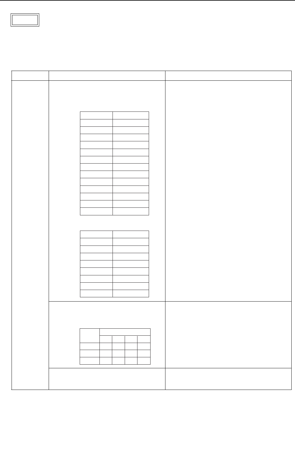
[ IX Troubleshooting ]
- 283 -
HWE09080 GB
1. Error Code
Total capacity error
2. Error definition and error detection method
The model total of indoor units in the system with one heat source unit exceeds limitations.
3. Error source, cause, check method and remedy,
7100
Error source Cause Check method and remedy
Heat source
unit
(1) The model total of indoor units in the sys-
tem with one heat source unit exceeds the
following table.
1) Check the model total (capacity code total) of
units connected.
2) Check the model name (capacity code) of the
connected indoor unit set by the switch (SW2 on
indoor unit board).
When the model name set by the switch is differ-
ent from that of the unit connected, turn off the
power source of the heat source and the indoor
units, and change the setting of the model name
(capacity code).
(2) The model selection switches (SW5-1 - 5-
4) on the heat source unit are set incor-
rectly.
Check the setting for the model selection switch
on the heat source unit (Dipswitches SW5-1 - 5-
4 on the heat source unit control board).
(3) The heat source unit and the auxiliary unit
(OS) that is connected to the same system
are not properly connected.
Confirm that the TB3 on the OC and OS are
properly connected.
P72 model
P96 model
P120 model
P144 model
P168 model
P192 model
P216 model
P240 model
P264 model
P288 model
P312 model
P336 model
P360 model
93
124
156
187
218
249
280
312
343
374
405
436
468
P72 model
P96 model
P120 model
P144 model
P168 model
P192 model
P216 model
P240 model
108
144
180
216
252
288
324
360
Capacity Total
Model
<PQHY>
Capacity Total
Model
<PQRY>
72 model
96 model
120 model
SW5
OFF ON OFF OFF
ON ON OFF OFF
OFF OFF ON OFF
1234
Model
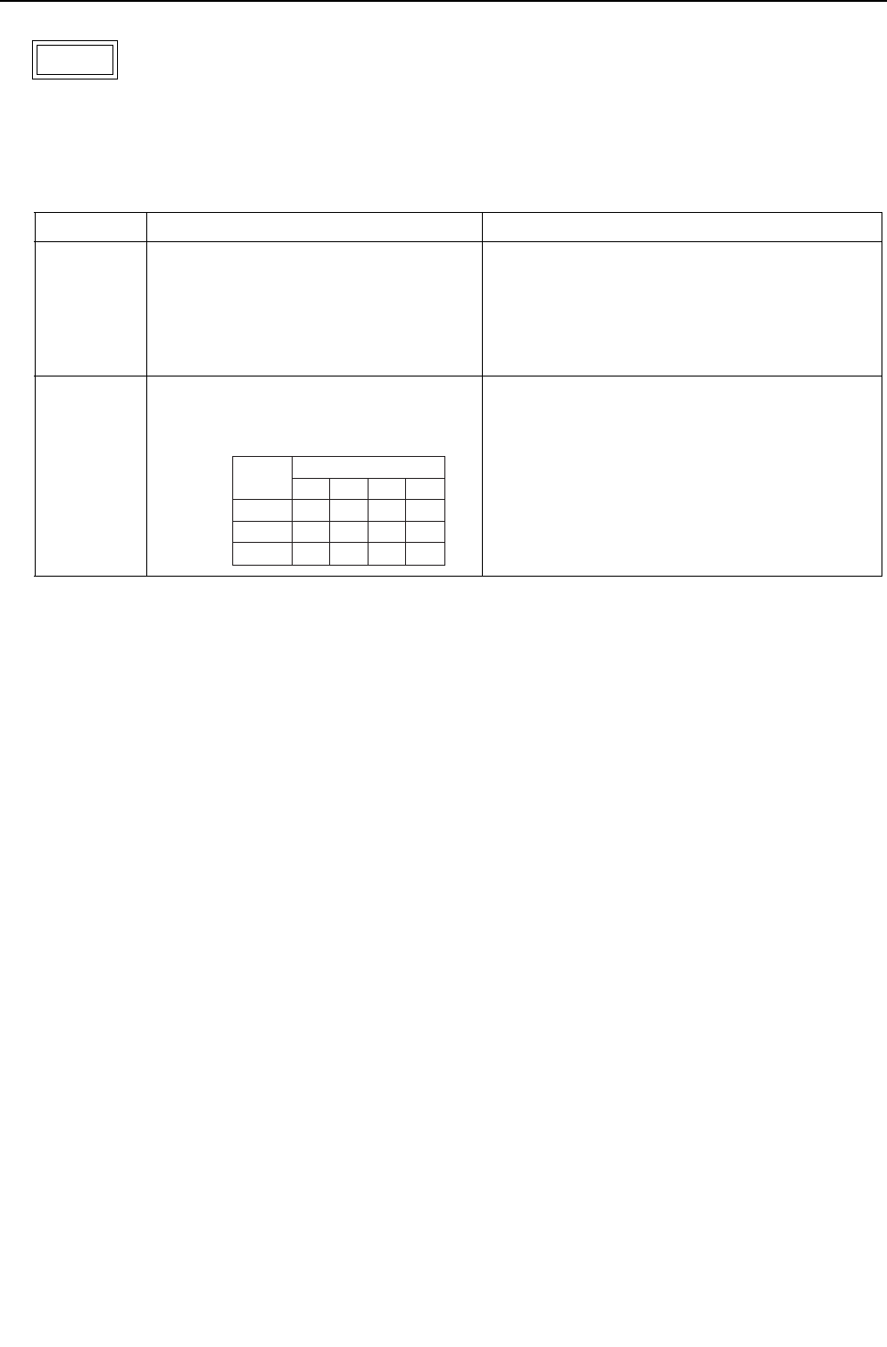
[ IX Troubleshooting ]
- 284 -
HWE09080 GB
1. Error Code
Capacity code setting error
2. Error definition and error detection method
Connection of incompatible (wrong capacity code) indoor unit or heat source unit
3. Error source, cause, check method and remedy
7101
Error source Cause Check method and remedy
Heat source
unit
Indoor unit
(1) The model name (capacity code) set by
the switch (SW2) is wrong.
1) Check the model name (capacity code) of the in-
door unit which has the error source address set by
the switch (SW2 on indoor unit board).
When the model name set by the switch is different
from that of the unit connected, turn off the power
source of the heat source and the indoor units, and
change the setting of the capacity code.
*The capacity of the indoor unit can be
confirmed by the self-diagnosis function
(SW1 operation) of the heat source unit.
Heat source
unit
(2) The model selection switches (SW5-1 -
5-4) on the heat source unit are set in-
correctly.
Check the setting for the model selection switch on
the heat source unit (Dipswitches SW5-1 - 5-4 on
the heat source unit control board).
72 model
96 model
120 model
SW5
OFF ON OFF OFF
ON ON OFF OFF
OFF OFF ON OFF
1234
Model
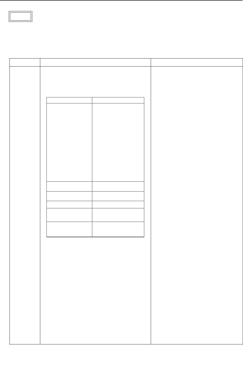
[ IX Troubleshooting ]
- 285 -
HWE09080 GB
1. Error Code
Wrong number of connected units
2. Error definition and error detection method
The number of connected indoor units is "0" or exceeds the allowable value.
3. Error source, cause, check method and remedy
7102
Error source Cause Check method and remedy
Heat source
unit
(1) Number of indoor units connected to the heat
source terminal block (TB3) for indoor-heat source
transmission lines exceeds limitations described
below.
1) Check whether the number of units con-
nected to the heat source terminal block
(TB3) for indoor-heat source transmission
lines does not exceed the limitation. (See
(1) and (2) on the left.)
2) Check (2) - (3) on the left.
3) Check whether the transmission line for
the terminal block for centralized control
(TB7) is not connected to the terminal
block for the indoor-heat source transmis-
sion line (TB3).
4) Check the setting for the model selection
switch on the heat source unit (Dipswitch-
es SW5-7 on the heat source unit control
board).
(2) Disconnected transmission line from the heat
source unit or BC controller
(3) Short-circuited transmission line
When (2) and (3) apply, the following display will
appear.
M-NET remote controller
Nothing appears on the remote controller be-
cause it is not powered.
MA remote controller
"HO" or "PLEASE WAIT" blinks.
(4) The model selection switch (SW5-7) on the heat
source unit is set to OFF. (Normally set to ON)
(5) Heat source unit address setting error
The heat source units in the same refrigerant cir-
cuit do not have sequential address numbers.
(6) A type-G BC controller is connected to a unit P144
model or above.
Restriction on the number of units
Number of units
0 or 1
0 or 1
1
(P72 - P120 models only)
0,1 or 2
1 - 15 : P72 model
1 - 20 : P96 model
1 - 26 : P120 model
1 - 31 : P144 model
1 - 36 : P168 model
1 - 41 : P192 model
2 - 46 : P216 model
2 - 50 : P240 - P360 models
1 - 18 : P72 model
1 - 24 : P96 model
1 - 30 : P120 model
1 - 36 : P144 model
1 - 42 : P168 model
1 - 48 : P192 model
2 - 50 : P216 - P240 models
1 : P72 - P120 models
2 : P144 - P240 models
3 : P264 - P360 models(PQHY only)
Total number of indoor units
Total number of LOSSNAY
units (During auto address
start-up only)
Number of Sub BC controllers
Number of
Main BC controllers
Number of BC controllers
Total number of heat source
units
<PQHY>
<PQRY>
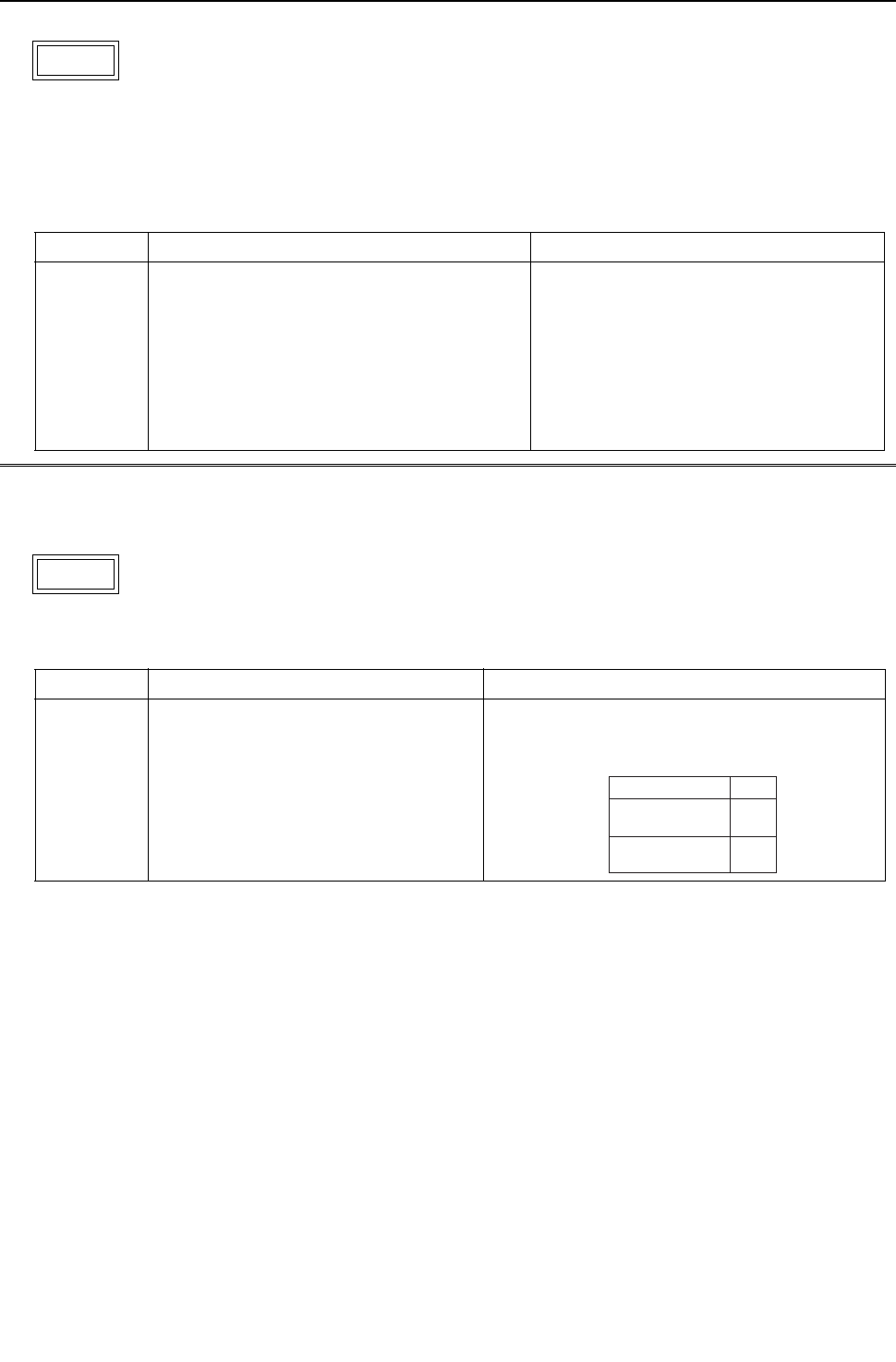
[ IX Troubleshooting ]
- 286 -
HWE09080 GB
1. Error Code
Address setting error
2. Error definition and error detection method
Erroneous setting of OC unit address
Erroneous setting of BC controller address
3. Cause, check method and remedy
1. Error Code
Attribute setting error
2. Error definition and error detection method
7105
Error source Cause Check method and remedy
Heat source
unit
BC controller
Erroneous setting of OC unit address
The address of heat source unit is not being set to
51 - 100.
The address of BC controller is not set to 51 - 100.
Check that the heat source unit and BC con-
troller addresses are set to 00 or a number be-
tween 51 and 100.
If the heat source unit address is out of the val-
id range, reset the address with the power to
the heat source unit turned off.
If the BC controller address is out of the valid
range, reset the address with the power to both
the heat source unit and BC controller turned
off.
7106
Error source Cause Check method and remedy
- A remote controller for use with indoor
units, such as the MA remote controller, is
connected to the OA processing unit whose
attribute is FU.
To operate the OA processing unit directly via a re-
mote controller for use with indoor units, such as the
MA remote controller, set the DIP SW 3-1 on the OA
processing unit to ON.
SW3-1
OFF
ON
Interlocked operation
with the indoor unit
Operation Method
Direct operation via the
MA remote controller
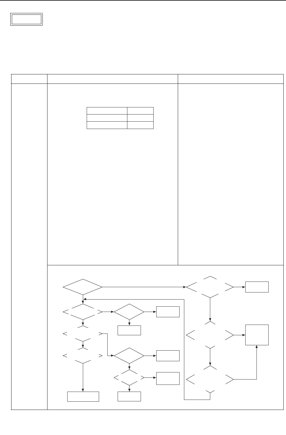
[ IX Troubleshooting ]
- 287 -
HWE09080 GB
1. Error Code
Port setting error
2. Error definition and error detection method
The port with wrong number is connected to the indoor unit.The model total connected to the port is greater than the specifi-
cation.
3. Cause, check method and remedy
7107
Error source Cause Check method and remedy
BC controller (1) Model total of indoor units per each port or per
each port merge is greater than the specification.
Before resetting the port number using
the port number setting switch or the
model using the model (capacity code)
setting switch, turn off the power of the
heat source unit, the BC controller and
the indoor unit.
(2) 4 or more indoor units are connected to the same
port.
(3) When two ports are used, the port with the smaller
number is not connected to the indoor unit.
(4) For the address of the BC controller (Sub 1 or 2),
50 is not added to the smallest indoor unit address,
which is connected to the BC controller (Sub1 or
2).
(5) In the system to which multiple BC controllers are
connected, the indoor unit address connected to
the BC controller is not set as shown below.
(i) The indoor unit address which is connected to
the BC controller (main)
(ii) The indoor unit address which is connected to
the BC controller (Sub1)
(iii) he indoor unit address which is connected to
the BC controller (Sub2)
Address setting
(i)<(ii)<(iii)
*(ii) and (iii) can be reversed.
Model totalTotal port number
Single branching
2 branches merge
54
96
Change the port No.
Is there a BC
controller (Sub)?
Are 4 or more indoor units
connected to the same port?
Is the model total of indoor
units connected to the same port
greater than the item (1)?
When two ports are used,
is the port with the smallest number
connected to the indoor unit?
YES
YES
NO
YES
YES
NO
For the address of the BC
controller (Sub), is 50 added to
the smallest indoor unit address,
which is connected to the
BC controller (Sub)?
Is the address of the indoor
unit, which is connected to the the
BC controller (Main) ,smaller than
that of the indoor, which is
connected to the BC controller
(Sub 1 or 2)?
YES
YES
Is the address of the indoor
unit, which is connected to the the
BC controller (Main), smaller than
that of the indoor, which is
connected to the BC controller
(Sub 1 or 2)?
YES
NO
NO
NO
NO
NO
Change the port No.
NO
Change the BC
controller
(Sub) address.
NO
NO
Change the indoor
unit address or
change the BC
controller address
YES
Change the port No.
YES
Change the set
indoor unit model
(capacity code).
Port No. setting error?
Port No. setting error?
The wrong model
(capacity code) is set.
Adjust the piping
connection to the port.
Adjust the piping
connection to the port.
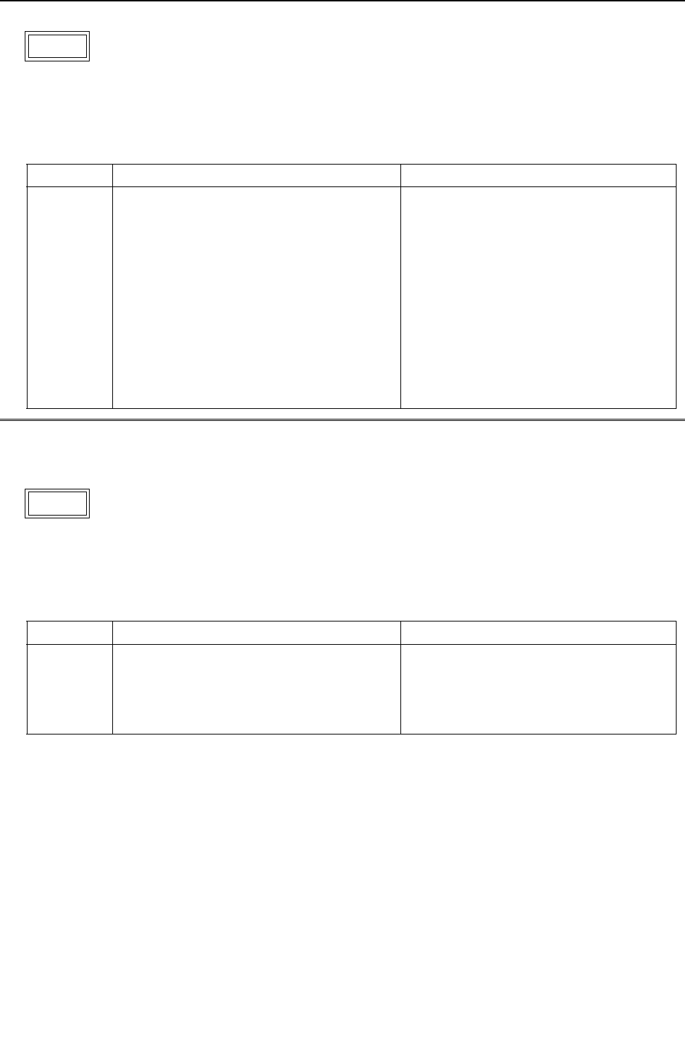
[ IX Troubleshooting ]
- 288 -
HWE09080 GB
1. Error Code
Connection information signal transmission/reception error
2. Error definition and error detection method
The given indoor unit is inoperable because it is not properly connected to the heat source unit in the same system.
3. Error source, cause, check method and remedy
1. Error Code
Remote controller sensor fault
2. Error definition and error detection method
This error occurs when the temperature data is not sent although the remote controller sensor is specified.
3. Error source, cause, check method and remedy
7110
Error source Cause Check method and remedy
Heat source
unit
(1) Power to the transmission booster is cut off. 1) Confirm that the power to the transmission
booster is not cut off by the booster being
connected to the switch on the indoor unit.
(The unit will not function properly unless the
transmission booster is turned on.)
(2) Power resetting of the transmission booster
and heat source unit.
->Reset the power to the heat source unit.
(3) Wiring failure between OC and OS 2) Confirm that the TB3 on the OC and OS are
properly connected.
(4) Broken wire between OC and OS. 3) Check the model selection switch on the
heat source unit (Dipswitch SW5-7 on the
control board.).
(5) The model selection switch (SW5-7) on the
heat source unit is set to OFF. (Normally set to
ON)
7111
Error source Cause Check method and remedy
Indoor unit
OA process-
ing unit
The remote controller without the temperature
sensor (the wireless remote controller or the
ME compact remote controller (mounted
type)) is used and the remote controller sen-
sor for the indoor unit is specified. (SW1-1 is
ON.)
Replace the remote controller with the one
with built-in temperature sensor.
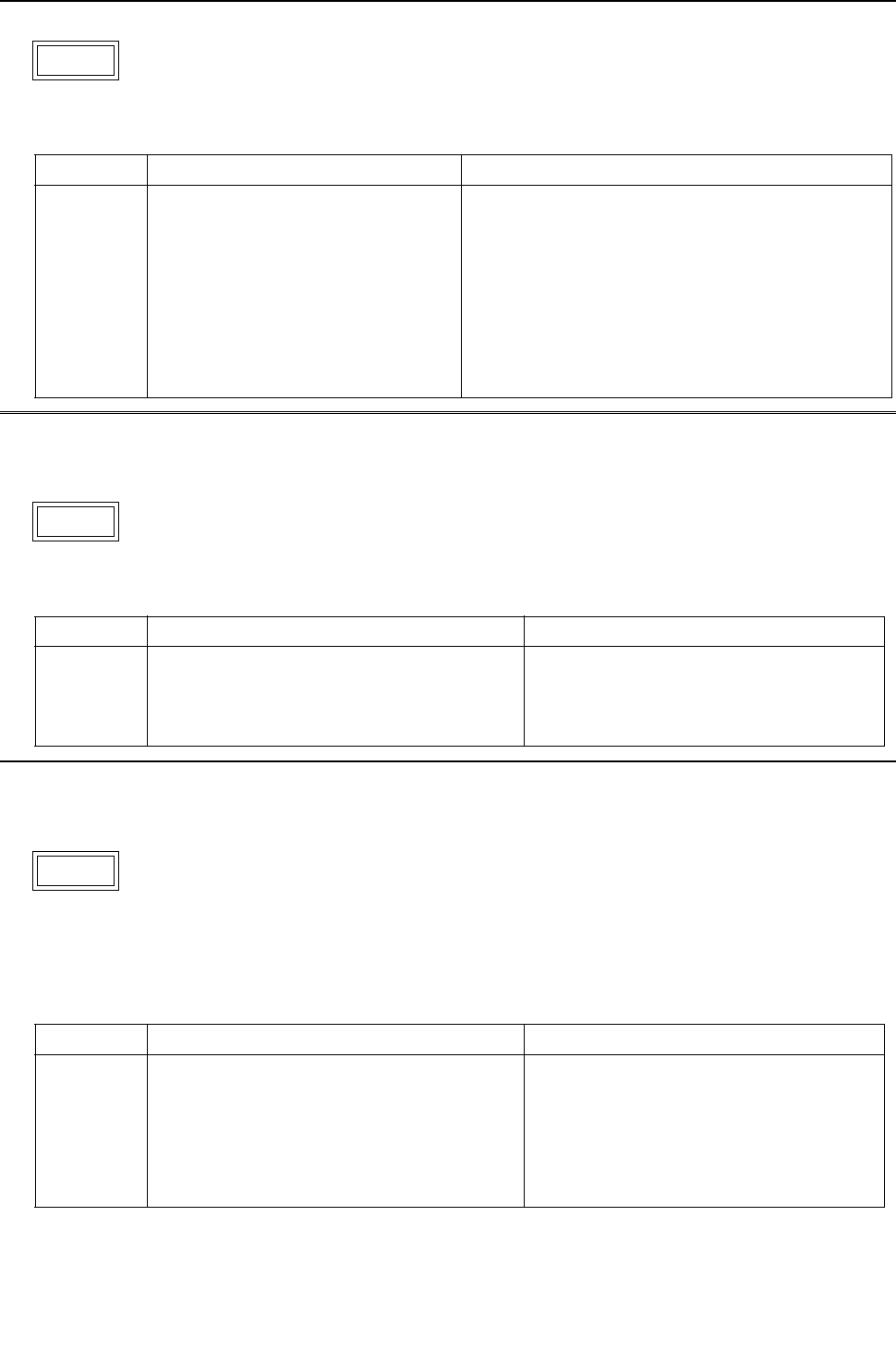
[ IX Troubleshooting ]
- 289 -
HWE09080 GB
1. Error Code
Function setting error
2. Error source, cause, check method and remedy
1. Error Code
Model setting error
2. Error source, cause, check method and remedy
1. Error Code
Incompatible unit combination
2. Error definition and error detection method
The check code will appear when the indoor units with different refrigerant systems are connected.
3. Error source, cause, check method and remedy
7113
Error source Cause Check method and remedy
Heat source
unit
(1) Wiring failure 1) Control board connector
Check the CNTYP2,4,5 connector connection.
Inverter board connector
Check the CNTYP connector connection.
(2) Disconnected connector, short cir-
cuit, contact failure
2) Check the compatibility of the circuit board, and replace
it with a correct one if necessary.
(3) Incompatibility between the control
board and inverter board (Replace-
ment of the circuit board with the
wrong one)
3) Check the model selection switch on the heat source
unit (Dipswitch SW5-7 on the control board.).
7117
Error source Cause Check method and remedy
Heat source
unit
(1) Wiring failure 1) Control board connector
Check the CNTYP2,4,5 connector connec-
tion.
Inverter board connection
Check the CNTYP connector connection
(2) Disconnected connector, short circuit, contact
failure
7130
Error source Cause Check method and remedy
Heat source
unit
The connected indoor unit or BC controller is
exclusively for use with R22 or R407C. An in-
compatible indoor unit or BC controller is con-
nected.
The M-NET connection adapter is connected
to the indoor unit system in a system in which
the Slim Model (A control) of units are con-
nected to the M-NET.
Check the model names of the connected in-
door unit and the BC controller.
Check whether the connecting adapter for
M-NET is not connected to the indoor unit.
(Connect the connecting adapter for M-NET
to the heat source unit.)

[ IX Troubleshooting ]
- 290 -
HWE09080 GB
-1- Troubleshooting according to the remote controller malfunction or the external input error
In the case of MA remote controller
1. Phenomena
Even if the operation button on the remote controller is pressed, the display remains unlit and the unit does not start run-
ning.(Power indicator does not appear on the screen.)
(1) Cause
1) The power is not supplied to the indoor unit.
The main power of the indoor unit is not on.
The connector on the indoor unit board has come off.
The fuse on the indoor unit board has melted.
Transformer failure and disconnected wire of the indoor unit.
2) Incorrect wiring for the MA remote controller
Disconnected wire for the MA remote controller or disconnected line to the terminal block.
Short-circuited MA remote controller wiring
Incorrect wiring of the MA remote controller cables
Incorrect connection of the MA remote wiring to the terminal block for transmission line (TB5) on the indoor unit
Wiring mixup between the MA remote controller cable and 220 - 240 VAC power supply cable
Reversed connection of the wire for the MA remote controller and the M-NET transmission line on the indoor unit
3) The number of the MA remote controllers that are connected to an indoor unit exceeds the allowable range (2 units).
4) The length or the diameter of the wire for the MA remote controller are out of specification.
5) Short circuit of the wire for the remote display output of the heat source unit or reversed polarity connection of the relay.
6) The indoor unit board failure
7) MA remote controller failure
(2) Check method and remedy
1) Measure voltages of the MA remote controller terminal (among 1 to 3).
If the voltage is between DC 9 and 12V, the remote controller is a failure.
If no voltage is applied, check the causes 1) and 3) and if the cause is found, correct it.
If no cause is found, refer to 2).
2) Remove the wire for the remote controller from the terminal block (TB13) on the MA remote controller for the indoor unit, and
check voltage among 1 to 3.
If the voltage is between DC 9 and 12 V, check the causes 2) and 4) and if the cause is found, correct it.
If no voltage is applied, check the cause 1) and if the cause is found, correct it.
If no cause is found, check the wire for the remote display output (relay polarity).
If no further cause is found, replace the indoor unit board.
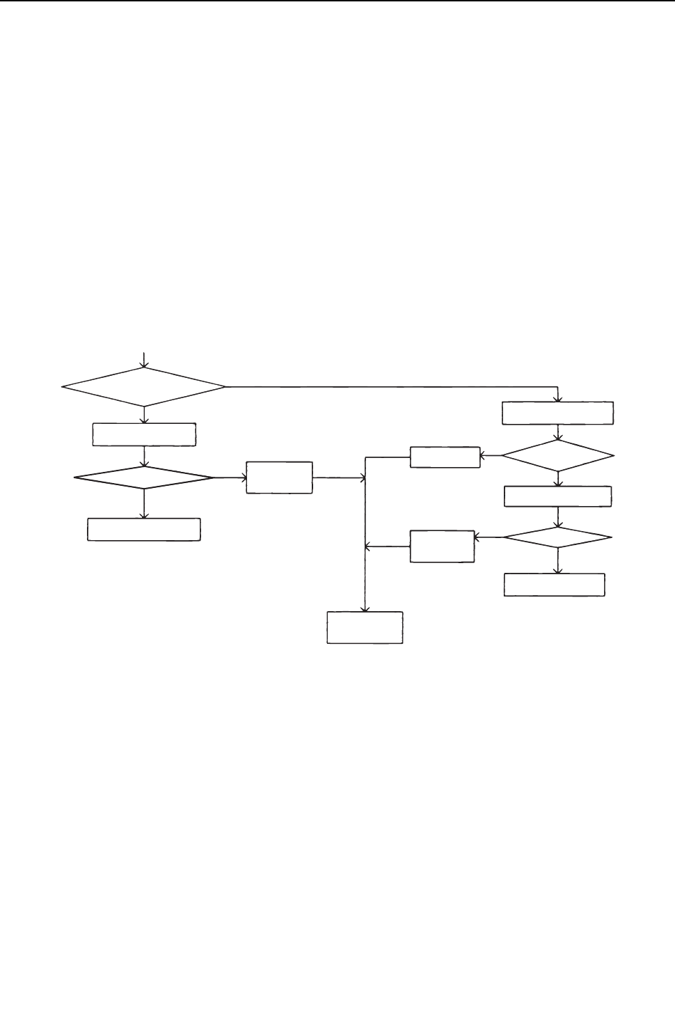
[ IX Troubleshooting ]
- 291 -
HWE09080 GB
In the case of MA remote controller
2. Phenomena
When the remote controller operation SW is turned on, the operation status briefly appears on the display, then it goes off,
and the display lights out immediately, and the unit stops.
(1) Cause
1) The power for the M-NET transmission line is not supplied from the heat source unit.
2) Short circuit of the transmission line.
3) Incorrect wiring of the M-NETtransmission line on the heat source unit.
Disconnected wire for the MA remote controller or disconnected line to the terminal block.
The indoor transmission line is connected incorrectly to the transmission terminal block for centralized controller (TB7).
The male power supply connectors on the multiple heat source units are connected to the female power supply switch con-
nector (CN40).
In the system to which the power supply unit for transmission lines is connected, the male power supply connector is connect-
ed to the female power supply switch connector (CN40) on the heat source unit.
4) Disconnected M-NET transmission line on the indoor unit side.
5) Disconnected wire between the terminal block for M-NET line (TB5) of the indoor unit and the indoor unit board (CN2M) or
disconnected connector.
(2) Check method and remedy
1) When 2) and 3) above apply, check code 7102 will be displayed on the self-diagnosis LED on the heat source unit.
Refer to IX [4] -7- (2) "Troubleshooting transmission power circuit of heat source unit" for how to check item 1 in the flow chart
above.
YES
YES
YES
YES
NO
NO
NO
NO
Same symptom for all units in a
system with one heat source
unit?
Check the
self-diagnosis LED
Check 1).
Check for
2 and 3.
Check 4.
Measure voltages of the
terminal block for transmission
line (TB5) on the indoor unit.
17 - 30V?
Check 5.
Error found?
Indoor unit board or
MA remote controller failure
Correct
the error.
Correct the error.
Is the error code 7102
displayed?
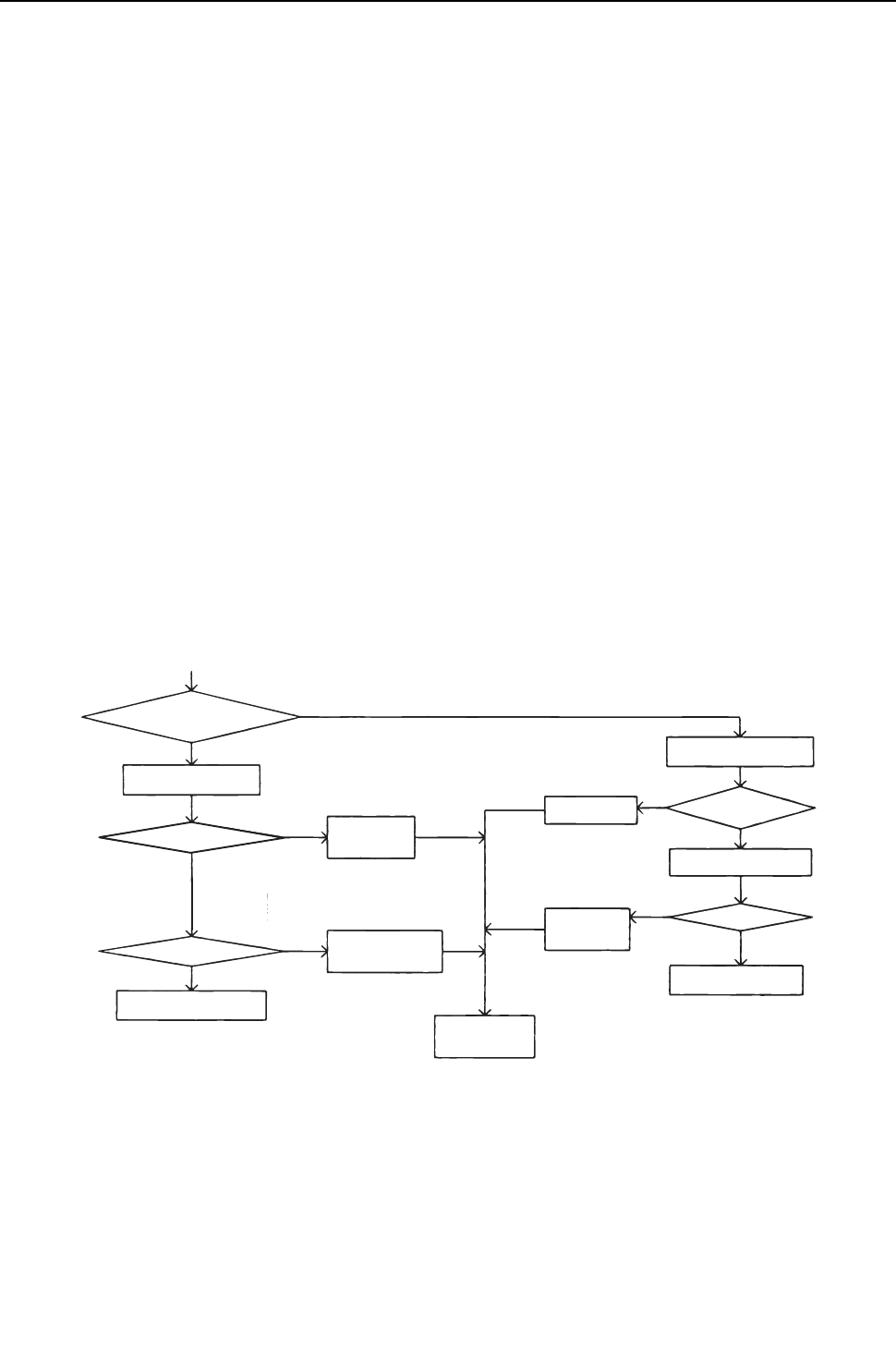
[ IX Troubleshooting ]
- 292 -
HWE09080 GB
In the case of MA remote controller
3. Phenomena
"HO" or "PLEASE WAIT" display on the remote controller does not disappear, and no operation is performed even if the button
is pressed. ("HO" or "PLEASE WAIT" display will normally turn off 5 minutes later after the power on.)
(1) Cause
1) The power for the M-NET transmission line is not supplied from the heat source unit.
2) Short-circuited transmission line
3) Incorrect wiring of the M-NET transmission line on the heat source unit.
Disconnected wire for the MA remote controller or disconnected line to the terminal block.
The indoor transmission line is connected incorrectly to the transmission terminal block for centralized controller (TB7).
The male power supply connectors on the multiple heat source units are connected to the female power supply switch con-
nector (CN40).
In the system to which the power supply unit for transmission lines is connected, the male power supply connector is connect-
ed to the female power supply switch connector (CN40) on the heat source unit
4) Disconnected M-NET transmission line on the indoor unit.
5) Disconnected wire between the terminal block for M-NET line (TB5) of the indoor unit and the indoor unit board (CN2M) or
disconnected connector.
6) Incorrect wiring for the MA remote controller
Short-circuited wire for the MA remote controller
Disconnected wire for the MA remote controller (No.2) and disconnected line to the terminal block.
Reversed daisy-chain connection between groups
Incorrect wiring for the MA remote controller to the terminal block for transmission line connection (TB5) on the indoor unit
The M-NET transmission line is connected incorrectly to the terminal block (TB13) for the MA remote controller.
7) The sub/main setting of the MA remote controller is set to sub.
8) 2 or more main MA remote controllers are connected.
9) Indoor unit board failure (MA remote controller communication circuit)
10) Remote controller failure
11) Heat source unit failure (Refer to IX [8] Troubleshooting Using the Heat source Unit LED Error Display.)(page 356)
(2) Check method and remedy
1) When 2) and 3) above apply, check code 7102 will be displayed on the self-diagnosis LED on the heat source unit.
Refer to IX [4] -7- (2) "Troubleshooting transmission power circuit of heat source unit" for how to check item 1 in the flow chart
above.
YES
YES
YES
NO
NO
YES
YES
NO
NO
NO
Check the self-diagnosis LED
Error found?
Error found?
Replace the ME remote
controller with the MA
remote controller
Check for 5 and 6.
17 - 30V?
Same symptom for all units in a
system with one heat source
unit?
Check (1).
Check
2 and 3.
Check 4.
Correct
the error.
Correct
the error.
Measure voltages of the
terminal block for transmission
line (TB5) on the indoor unit.
Is the error code 7102
displayed?
Indoor unit board or
MA remote controller failure
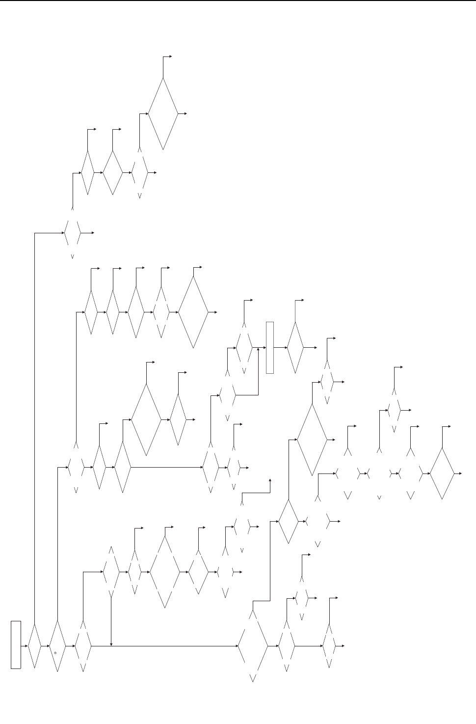
[ IX Troubleshooting ]
- 293 -
HWE09080 GB
Flow chart
Even if the operation button on the remote controller is pressed, the indoor and the heat source units do not start running.
YES
Blinking?
Is " " displayed on
the remote controller?
NO
NO
NO
YES
YES
When all wires used for
grouping are disconnected, is at
least one of the LED2 on the
grouped indoor units lit?
YES
Check the wiring
Is there an indoor unit on
which LED2 is turned off?
If operated afterwards,
error 6602 or
6607 occurs.
Check the voltage between
the MA remote controller
terminals (A and B).
9-13VDC if the voltage is applied
and 0V if no voltage is applied.
Is LED1 on the indoor unit
control board lit?
(Blinks for 2 or 3 seconds
approximately every
20 seconds)
Does the number of the MA
remote controllers that are
connected to an indoor
unit exceed the allowable
range (2 units)?
Blinking?
(Turns on momentarily
approximately every
20 seconds)
MA remote controller
→To "1. Phenomenon"
MA remote controller
→To "1. Phenomenon"
MA remote controller
→To "1. Phenomenon"
To "2. Phenomenon"
MA remote controller
→To "1. Phenomenon"
To "3. Phenomenon"
MA remote controller
→To "1. Phenomenon"
Check No. 1 refrigerant
circuit.
To "2. Phenomenon"
MA remote controller
→To "1. Phenomenon"
Check the refrigerant circuit.
To "2. Phenomenon"
Check for the M-NET
transmission line.
Replace the indoor unit control board.
Connect 2 remote controllers or less.
Restore the original MA remote
controller wiring connections after repairs.
Check whether the screw
on the wire is not loose.
Is LED2 on the indoor unit
control board blinking?
When the unit is operated with
the remote controller, will "ON"
appear on the display?
Is "Centralized"
displayed?
"HO"/"PLEASE WAIT" keeps
blinking on the MA remote controller.
Is only the power source of the
indoor unit turn turned on again?
DEMAND by MELANS?
External thermo
input setting?
(SW3-3=ON)
Does an error occur when
the power is reset?
Does the unit work properly
when the wire for the MA
remote controller is
daisy-chained again?
Is LED1 on the indoor
unit control board lit?
Does the MA remote controller
work properly when it is connected
to the specified indoor unit?
Does an error occur when
the power is reset?
Running group operation with
the MA remote controller?
Is the unit grouped
with the equipment package
indoor unit?
No fault with the equipment
package indoor unit?
Does an error occur when
the power is reset?
Check that no error occurs in other indoor units.
Check the indoor unit on
which LED2 is lit.
All the indoor unit
power failure?
All the indoor unit
power failure?
Error display?
Error display?
Thermo is OFF?
Is operation possible?
Short circuit of the
remote controller?
After turning the power on, check whether "HO"/
"PLEASE WAIT" is displayed on the remote controller.
After more than 20 seconds since
turning the power on, is LED2 check
of the indoor control board still
displayed?
Is the operation by MELANS
forbidden or the input from external control
equipment allowed (SWC=ON)?
Is the compulsory
thermo OFF (SWA)
switch set to "2" or "3"?
Although No.1 refrigerant circuit
is normal, No.2 or No.3
refrigerant circuit remain stopped.
Running group operation with
the MA remote controller?
Does the indoor unit make
an instantaneous stop?
Power supply voltage
AC198~264V?
NO
YES
NO
NO
NO
NO
NO
NO
NO
NO
When no error occurs
NO
NO
NO
Keep displaying
for 5 or more minutes.
NO
NO
NO
NO
NO
NO
NO
NO
NO
NO
NO
NO
Check the
power supply.
Check the wire for
the remote controller.
NO
Replace the indoor unit control board.
NO
NO
NO
NO
NO
Replace the MA
remote controller.
NO
Replace the remote controller
or the indoor control board.
YES
Replace the indoor unit control
board where an error occurs.
Keep the operation.
NO
NO
NO
NO
Keep the operation.
YES
YES
YES
YES
Power on
YES
Refer to the self-diagnosis list
for the displayed error code.
YES
Normal
Turns off within approximately 5 minutes.
After the main power on, start the MA remote
controller. "HO" display will appear.
YES
Normal
"Centralized" is displayed.
YES
Refer to the error code list.
YES
YES
YES
Normal
YES
Normal
(Is the thermo OFF
signal input?)
YES
Set the SWA to "1".
YES
Refer to the self-diagnosis list for
the displayed error code.
YES
YES
YES
YES
Check the equipment
package indoor unit.
YES
Replace the remote controller or
the indoor control board.
Replace the indoor unit control board.
YES
YES
YES
Replace the remote controller
or the indoor control board.
Normal
(Operate the unit with
external control equipment)
YES
YES
Replace the indoor
unit control board.
Check the
power supply.
YES
YES
YES
YES
Check the voltage
between the MA remote controller
terminal blocks (TB15) (A and B).
9-13VDC if the voltage
is applied and 0V if no voltage
is applied.
NO
Disconnected wire for
the remote controller?
Disconnected wire to
the terminal block?
Disconnected relay connector?
NO
Are the length or the diameter
of the wire for MA remote controller
out of specification?
NO
YES
YES
Use the wire that meets the specification.
Replace the wire for the MA remote controller.
YES
Check for the wire for
the remote controller.
Keep the operation.
YES
Replace the indoor
unit control board.
YES
YES
YES
Power on

[ IX Troubleshooting ]
- 294 -
HWE09080 GB
In case of ME remote controller
1. Phenomena
Even if the operation button on the remote controller is pressed, the display remains unlit and the unit does not start running.
(Power indicator does not appear on the screen.)
(1) Cause
1) The power for the M-NET transmission line is not supplied from the indoor unit.
2) Short circuit of the transmission line.
3) Incorrect wiring of the M-NET transmission line on the heat source unit.
Disconnected wire for the MA remote controller or disconnected line to the terminal block.
The indoor transmission line is connected incorrectly to the transmission terminal block for centralized controller (TB7).
4) Disconnected transmission line on the remote controller.
5) Remote controller failure
6) Heat source unit failure (Refer to IX [8] Troubleshooting Using the Heat source Unit LED Error Display.)(page 356)
(2) Check method and remedy
1) Check voltage of the transmission terminal block for of the ME remote controller.
If voltage between is 17V and 30V -> ME remote controller failure
When voltage is 17V or less -> Refer to IX [4] -7- (2) "Troubleshooting transmission power curcuit of heat source unit".
2) When 2) and 3) above apply, check code 7102 will be displayed on the self-diagnosis LED on the heat source unit.
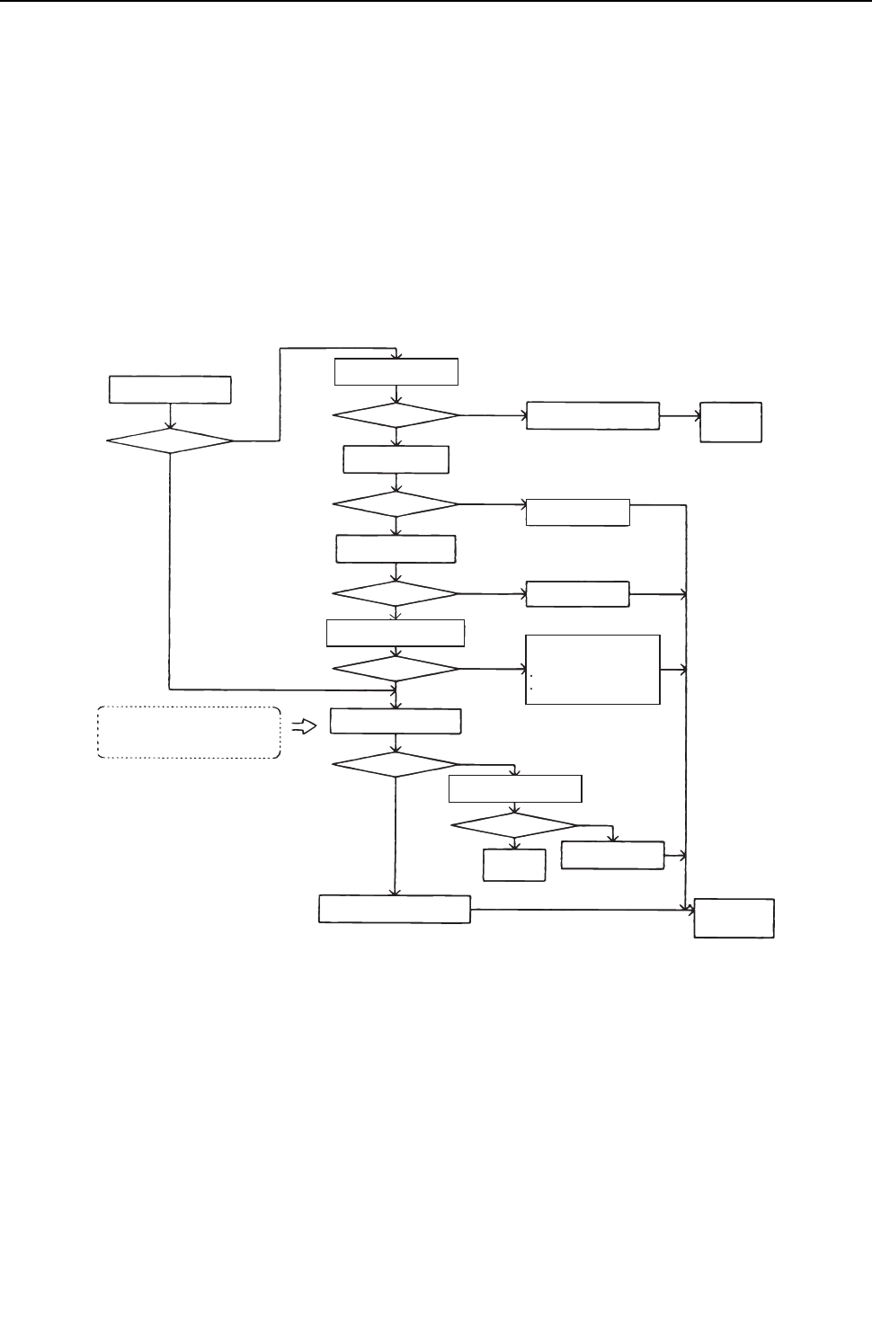
[ IX Troubleshooting ]
- 295 -
HWE09080 GB
In case of ME remote controller
2. Phenomena
When the remote controller operation SW is turned on, a temporary operation display is indicated, and the display lights out
immediately.
(1) Cause
1) The power is not supplied to the indoor unit.
The main power of the indoor unit (AC208/230V) is not on.
The connector on the indoor unit board has come off.
The fuse on the indoor unit board has melted.
Transformer failure and disconnected wire of the indoor unit
The indoor unit board failure
2) The heat source control board failure
As the indoor unit does not interact with the heat source unit, the heat source unit model cannot be recognized.
(2) Check method and remedy
YES
YES
YES
YES
YES
NO
NO
NO
NO
NO
NO
YES
*1 *1
Check LED1 on the
indoor unit control board.
Is it lit?
When it is lit When it is off
or cannot be checked
Check for the change of LED
display by operating dip
switch SW1 for self-diagnosis.
Check voltage of the power supply
terminal on the indoor unit.
AC208/230V?
Check the fuse on
the circuit board.
Melted?
Check 200V circuit for
short circuit and ground fault
Check the connection
of the connector.
Check the main power of
the power supply wire
Turn on the
power again.
Connector contact failure
Disconnected?
C
heck the resistance value
of the transformer
Within specification?
Check the cause of the
disconnected transformer.
Ground fault on the circuit board
Ground fault of the sensor and the LEV
Check self-diagnosis function
of heat source unit
Changed?
Changed?
Heat source unit board failure
Check self-diagnosis function of
heat source unit after the power on.
Accidental
error
Heat source unit control
board failure
Correct
the error.
*1. Refer to the parts catalog “transformer check”.
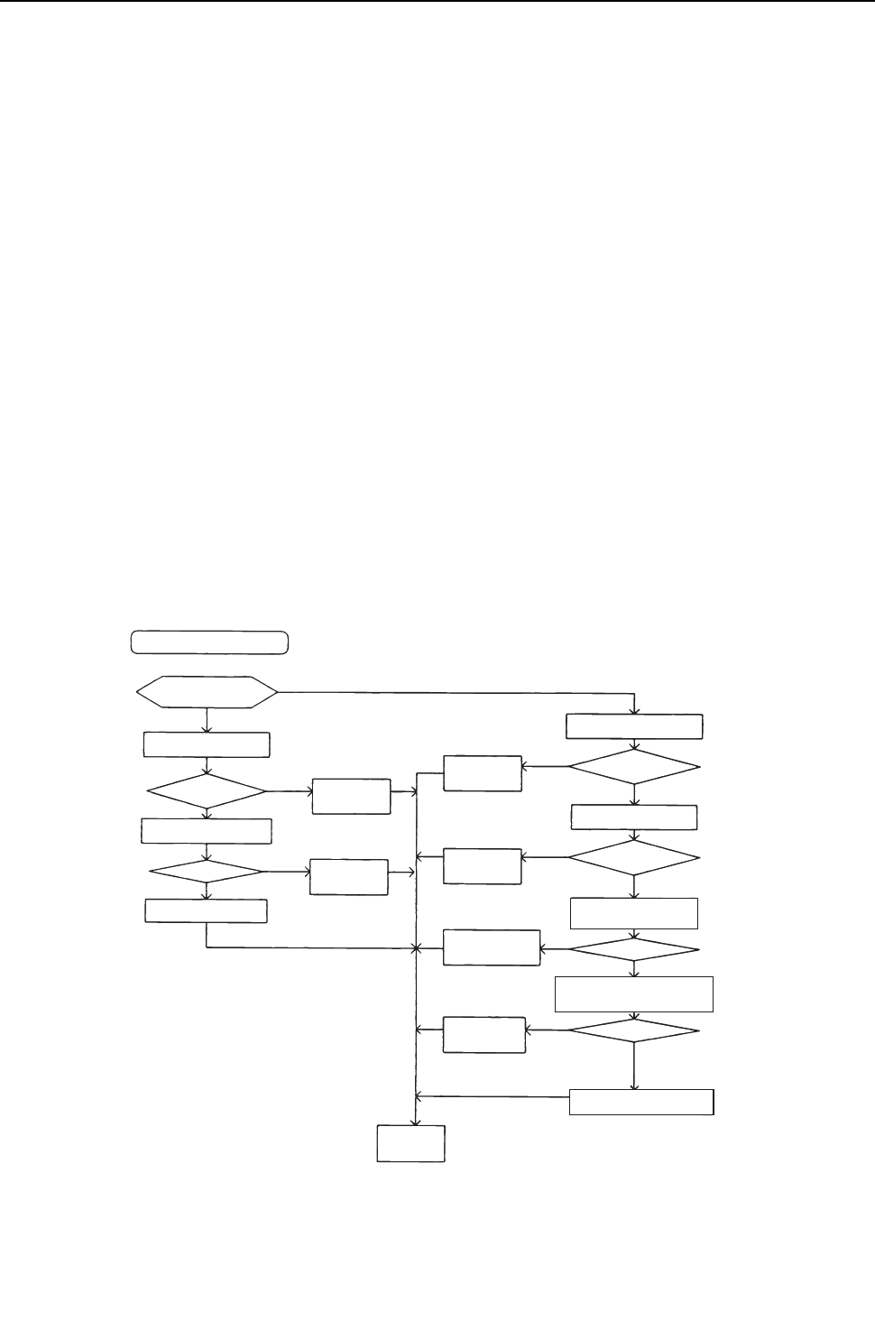
[ IX Troubleshooting ]
- 296 -
HWE09080 GB
In case of ME remote controller
3. Phenomena
"HO" display on the remote controller does not disappear, and no operation is performed even if the button is pressed.
(1) Cause
Without using MELANS
1) Heat source unit address is set to "00"
2) A wrong address is set.
The address of the indoor unit that is connected to the remote controller is incorrect. (It should equal the ME remote controller
address plus 100.)
A wrong address is set to the ME remote controller. (100 must be added to the address of the indoor unit.)
3) Faulty wiring of the terminal block for transmission line (TB5) of the indoor unit in the same group with the remote controller.
4) The centralized control switch (SW2-1) on the heat source unit is set to ON.
5) Disconnection or faulty wiring of indoor unit transmission line.
6) Disconnection between the terminal block for M-NET line connection (TB5) of the indoor unit and the male connector (CN2M)
7) The male power supply connectors on 2 or more heat source units are connected to the female power supply switch connector
(CN40) for the transmission line for centralized control.
8) Heat source unit control board failure
9) Indoor unit control board failure
10) Remote controller failure
Interlocking control with MELANS
1) No group registration is made using MELANS. (The indoor unit and the ME remote controller are not grouped.)
2) Disconnected transmission line for centralized control (TB7) of the heat source unit
3) The male power supply connector is connected to CN40 on more than one heat source unit, or the connector is connected to
CN40 on the heat source unit in the system to which a power supply unit for transmission line is connected.
Using MELANS
1) When MELANS is used, "HO" display on the remote controller will disappear when the indoor unit and the local remote con-
troller (ME remote controller) are grouped.
If "HO" does not disappear after the registration, check the causes (2) 1) - 3).
(2) Check method and remedy
YES
YES
YES
YES
YES
YES
YES
NO
NO
*1
*1. When the heat source unit address is set to 1 - 50, the address will be forcibly set to 100.
NO
NO
NO
NO
NO
Without using MELANS
Are all the units in the system
experiencing the same problem?
Check the address of
the heat source unit.
51 - 100?
Check the centralized centralized
switch (SW2-1) on the heat source unit.
ON?
Heat source unit control board failure
A wrong address is set
to the heat source unit.
Wrong switch setting
Change it from
ON to OFF.
A wrong address is
set to the ME
remote controller.
A wrong address is
set to the indoor unit.
Wrong wiring of the
M-NET transmission
line of the indoor unit
Disconnected
connector (CN2M)
Correct
the error.
Disconnected?
17 - 30V?
ME remote controller
- 100?
Check the address of the
indoor unit to be coupled.
Indoor unit + 100?
Check the address of the ME remote controller
on which "HO" is displayed.
Check connection between indoor M-NET
transmission terminal block (TB5) and the
male connector (CN2M)
Measure voltages of the terminal
block for M-NET transmission line
on the indoor unit.
Indoor unit board or
remote controller failure

[ IX Troubleshooting ]
- 297 -
HWE09080 GB
In case of ME remote controller
4. Phenomena
"88" appears on the remote controller when the address is registered or confirmed.
(1) Cause, check method and remedy
Cause Check method and remedy
An error occurs when the address is registered or con-
firmed. (common)
1. A wrong address is set to the unit to be coupled. (1) Confirm the address of unit to be coupled.
2. The transmission line of the unit to be coupled is dis-
connected or is not connected.
(2) Check the connection of transmission line.
3. Circuit board failure of the unit to be coupled (3) Check voltage of the terminal block for transmission
line of the unit to be coupled.
1) Normal if voltage is between DC17 and 30V.
4. Improper transmission line work 2) Check (4) in case other than 1).
Generates at interlocking registration between LOSS-
NAY and the indoor unit
5. The power of LOSSNAY is OFF. (4) Check for the main power of LOSSNAY.
Generates at confirmation of controllers used in the
system in which the indoor units connected to different
heat source units are grouped
6. The power of the heat source unit to be confirmed
has been cut off.
(5) Check the power supply of the heat source unit
which is coupled with the unit to be confirmed.
7. The power of the heat source unit to be confirmed
has been cut off.
(6) Check that the transmission line for centralized
control (TB7) of the heat source unit is not discon-
nected.
8. When the indoor units connected to different heat
source units are grouped without MELANS, the male
power supply connector is not connected to the fe-
male power supply switch connector (CN40) for the
transmission line for centralized control.
(7) Check voltage of the transmission line for central-
ized control.
9. The male power supply connectors on 2 or more heat
source units are connected to the female power sup-
ply switch connector (CN40) for the transmission line
for centralized control.
1) Normal when voltage is between 10V and 30V
10. In the system to which MELANS is connected, the
male power supply connector is connected to the fe-
male power supply switch connector (CN40) for the
transmission line for centralized control.
2) Check 8 - 11 described on the left in case other than
1).
11. Short circuit of the transmission line for centralized
control
[ IX Troubleshooting ]
- 298 -
HWE09080 GB
Both for MA remote controller and ME remote controller
1. Phenomena
Although cooling operation starts with the normal remote controller display, the capacity is not enough
(1) Cause, check method and remedy
Cause Check method and remedy
1. Compressor frequency does not rise sufficiently.
Faulty detection of pressure sensor.
Protection works and compressor frequency does
not rise due to high discharge temperature
Protection works and compressor frequency does
not rise due to high pressure
Pressure drops excessively.
(1) Check pressure difference between the detected
pressure by the pressure sensor and the actual
pressure with self-diagnosis LED.
-> If the accurate pressure is not detected, check
the pressure sensor. (Refer to the page on Trouble-
shooting of Pressure Sensor).
Note: Lower inlet pressure by the low pressure sensor
than the actual pressure causes insufficient capac-
ity.
SW1 setting
(2) Check temperature difference between the evapo-
rating temperature (Te) and the target evaporating
temperature (Tem) with self-diagnosis LED.
Note: Higher Te than Tem causes insufficient capacity.
SW1 setting
Note: Protection works and compressor frequency does
not rise even at higher Te than Tem due to high dis-
charge temperature and high pressure.
At high discharge temperature:
Refer to 1102.(page 231)
At high pressure:
Refer to 1302.(page 233)
2. Indoor unit LEV malfunction Refer to the page of LEV troubleshooting ([4] -4-
).(page 310)
Insufficient refrigerant flows due to LEV malfunc-
tion (not enough opening) or protection works and
compressor frequency does not rise due to pres-
sure drop.
Refrigerant leak from LEV on the stopping unit
causes refrigerant shortage on the running unit.
High pressure sensor
Low pressure sensor
ON
1 2 3 4 5 6 7 8 9 10
ON
1 2 3 4 5 6 7 8 9 10
SW1
SW1
1 2 3 4 5 6 7 8 9 10
Evaporating temperature Te
Target evaporating temperature Tem
ON
1 2 3 4 5 6 7 8 9 10
ON
SW1
SW1
[ IX Troubleshooting ]
- 299 -
HWE09080 GB
Cause Check method and remedy
3. Long piping length
The cooling capacity varies greatly depending on the
pressure loss. (When the pressure loss is large, the
cooling capacity drops.)
Check the piping length to determine if it is contrib-
uting to performance loss.
Piping pressure loss can be estimated from the
temperature difference between the indoor unit
heat exchanger outlet temperature and the satura-
tion temperature (Te) of 63LS. ->Correct the piping.
4. Piping size is not proper (thin)
5. Insufficient refrigerant amount
Protection works and compressor frequency does
not rise due to high discharge temperature.
Refer to 1-1. (Compressor frequency does not rise
sufficiently.)(page 298)
Refer to the page on refrigerant amount
adjustment(page 177)
6. Clogging by foreign object Check the temperature difference between in front
of and behind the place where the foreign object is
clogging the pipe (upstream side and downstream
side). When the temperature drops significantly, the
foreign object may clog the pipe.
-> Remove the foreign object inside the pipe.
7. The indoor unit inlet temperature is excessively.
(Less than 15°C [59°F] WB)
Check the inlet air temperature and for short cy-
cling. Change the environment where the indoor
unit is used.
8. Compressor failure
The amount of circulating refrigerant decreases due
to refrigerant leak in the compressor.
Check the discharge temperature to determine if
the refrigerant leaks, as it rises if there is a leak.
9. LEV3 malfunction
Sufficient liquid refrigerant is not be supplied to the
indoor unit as sufficient sub cool cannot be secured
due to LEV3 malfunction.
Refer to the page of LEV troubleshooting
( [4] -4- ).(page 310)
It most likely happens when there is little difference
or no difference between TH12 and TH15.
10. TH12, TH15 and 63HS1 sensor failure or faulty wir-
ing
LEV3 is not controlled normally.
Check the thermistor.
Check wiring.
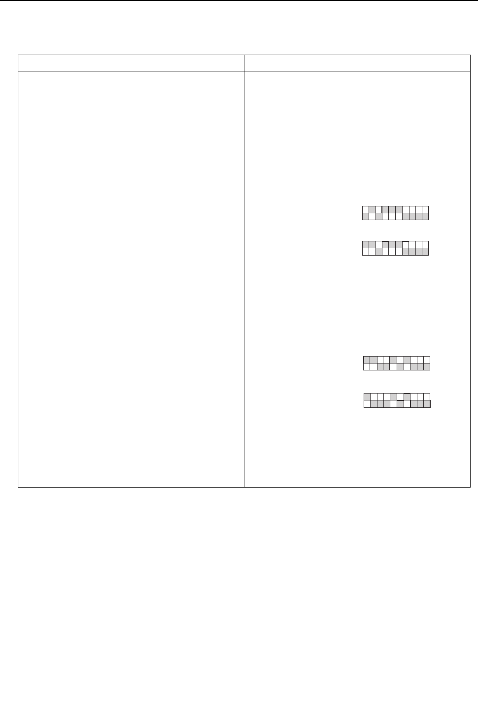
[ IX Troubleshooting ]
- 300 -
HWE09080 GB
2. Phenomena
Although heating operation starts with the normal remote controller display, the capacity is not enough.
(1) Cause, check method and remedy
Cause Check method and remedy
1. Compressor frequency does not rise sufficiently.
Faulty detection of pressure sensor.
Protection works and compressor frequency does
not rise due to high discharge temperature
Protection works and compressor frequency does
not rise due to high pressure.
(1) Check pressure difference between the detected
pressure by the pressure sensor and the actual
pressure with self-diagnosis LED.
-> If the accurate pressure is not detected, check
the pressure sensor.(Refer to the page on Trouble-
shooting of Pressure Sensor)
Note: Higher inlet pressure by the high pressure sensor
than the actual pressure causes insufficient capac-
ity.
SW1 setting
(2) Check the difference between the condensing tem-
perature (Tc) and the target condensing tempera-
ture (Tcm) with self-diagnosis LED.
Note: Higher Tc than Tcm causes insufficient capacity.
SW1 setting
Note: Protection works and compressor frequency does
not rise even at lower Tc than Tcm due to high dis-
charge temperature and high pressure.
At high discharge temperature:
Refer to 1102.(page 231)
At high pressure:
Refer to 1302.(page 233)
High pressure sensor
Low pressure sensor
ON
1 2 3 4 5 6 7 8 9 10
ON
1 2 3 4 5 6 7 8 9 10
SW1
SW1
Condensing temperature Tc
Target condensing temperature Tcm
ON
ON
1 2 3 4 5 6 7 8 9 10
1 2 3 4 5 6 7 8 9 10
SW1
SW1

[ IX Troubleshooting ]
- 301 -
HWE09080 GB
Cause Check method and remedy
2. Indoor unit LEV malfunction
Insufficient refrigerant flows due to LEV malfunction
(not enough opening).
Refer to the page of LEV troubleshooting
( [4] -4- ).(page 310)
3. Temperature reading error on the indoor unit piping
temperature sensor
If the temperature reading on the sensor is higher
than the actual temperature, it makes the subcool
seem smaller than it is, and the LEV opening de-
creases too much.
Check the thermistor.
4. Insulation failure of the refrigerant piping
5. Long piping length
Excessively long piping on the high pressure side
causes pressure loss leading to increase in the high
pressure.
Confirm that the characteristic of capacity drop due
to piping length.
-> Change the pipe
6. Piping size is not proper (thin)
7. Clogging by foreign object Check the temperature difference between the up-
stream and the downstream of the pipe section that
is blocked. Since blockage in the extended section
is difficult to locate, operate the unit in the cooling
cycle, and follow the same procedures that are
used to locate the blockage of pipe during cooling
operation.
->Remove the blockage in the pipe.
8. The indoor unit inlet temperature is excessively
high.(exceeding 28°C [82°F])
Check the inlet air temperature and for short cy-
cling. Change the environment where the indoor
unit is used.
9. Insufficient refrigerant amount
Protection works and compressor frequency does
not rise due to low discharge temperature
Refrigerant recovery operation is likely to start.
Refer to 2 - 1. (Compressor frequency does not rise
sufficiently.)(page 300)
Refer to the page on refrigerant amount
adjustment.(page 177)
10. Compressor failure (same as in case of cooling) Check the discharge temperature.
11. LEV3 actuation failure
A drop in the low pressure that is caused either by a
blockage of liquid pipe or by a pressure loss and the
resultant slowing of refrigerant flow causes a tenden-
cy for the discharge temperature to rise.
Refer to the page on troubleshooting the LEV ([4] -
4-).(page 310)

[ IX Troubleshooting ]
- 302 -
HWE09080 GB
3. Phenomena
Heat source unit stops at times during operation.
(1) Cause, check method and remedy
Cause Check method and remedy
The first stop is not considered as an error, as the
unit turns to anti-restart mode for 3 minutes as a pre-
liminary error.
(1) Check the mode operated in the past by displaying
preliminary error history on LED display with SW1.
Error mode
1 Abnormal high pressure (2) Reoperate the unit to find the mode that stops the
unit by displaying preliminary error history on LED
display with SW1.
2 Abnormal discharge air temperature
3 Heatsink thermistor failure
4 Thermistor failure -> Refer to the reference page for each error mode.
*Display the indoor piping temperature table with
SW1 to check whether the freeze proof operation
runs properly, and check the temperature.
5 Pressure sensor failure
6 Over-current break
7 Refrigerant overcharge
Note1: Frost prevention tripping only under cooling mode
may be considered in addition to the above. (Freeze
protection is detected by one or all indoor units.)
Note2: Even the second stop is not considered as an error
when some specified errors occur. (eg. The third
stop is considered as an error when the thermistor
error occurs.)
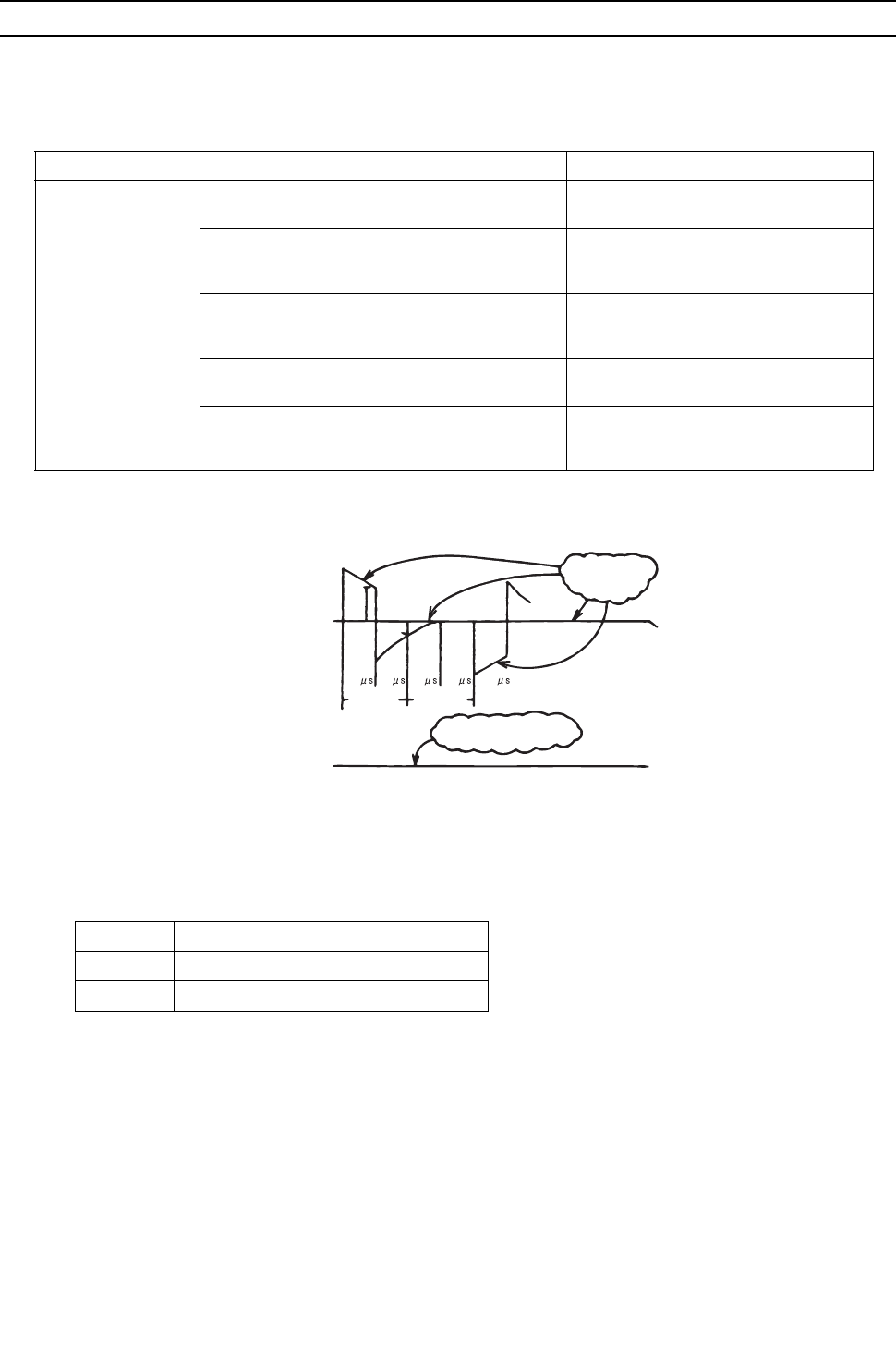
[ IX Troubleshooting ]
- 303 -
HWE09080 GB
[3] Investigation of Transmission Wave Shape/Noise
1. M-NET transmission
Control is performed by exchanging signals between the heat source unit and the indoor unit (ME remote controller) through
M-NET transmission. Noise interference on the transmission line will interrupt the normal transmission, leading to erroneous
operation.
(1) Symptoms caused by noise interference on the transmission line
(2) Wave shape check
Wave shape check
Check the wave pattern of the transmission line with an oscilloscope. The following conditions must be met.
1) Small wave pattern (noise) must not exist on the transmission signal. (Minute noise (approximately 1V) can be generated by
DC-DC converter or the inverter operation; however, such noise is not a problem when the shield of the transmission line is
grounded.)
2) The sectional voltage level of transmission signal should be as follows.
Cause Erroneous operation Error code Error code definition
Noise interference on
the transmission line
Signal is transformed and will be misjudged as the
signal of another address.
6600 Address overlap
Transmission wave pattern is transformed due to
the noise creating a new signal
6602 Transmission pro-
cessor hardware er-
ror
Transmission wave pattern is transformed due to
the noise, and will not be received normally leading
to no acknowledgement (ACK).
6607 No ACK error
Transmission cannot be performed due to the fine
noise.
6603 Transmission line
bus busy error
Transmission is successful; however, the acknowl-
edgement (ACK) or the response cannot be re-
ceived normally due to the noise.
6607
6608
No ACK error
No response error
Logic Voltage level of the transmission line
0V
HL = 2.5V or higher
1V
BN = 1.3V or below
[With transmission]
[Without transmission]
No fine noise allowed
No fine noise
allowed
52 52 52 52 52
V
BN
V
HL
Logic "0" Logic "1"
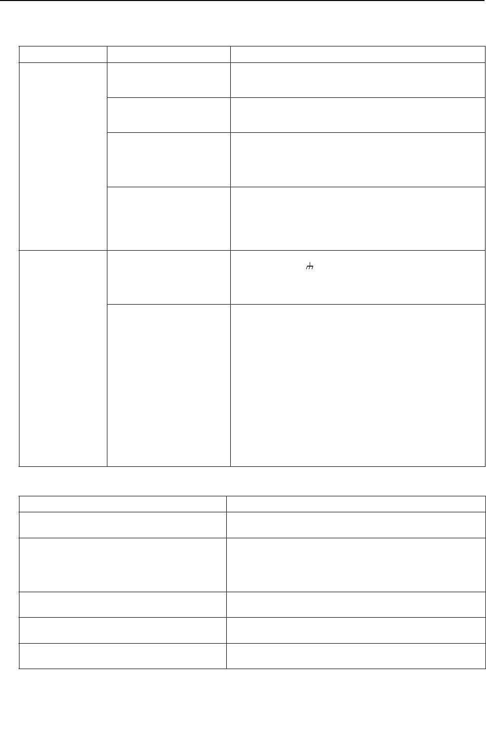
[ IX Troubleshooting ]
- 304 -
HWE09080 GB
(3) Check method and remedy
1) Measures against noise
Check the followings when noise exists on the wave or the errors described in (1) occur.
2) Check the followings when the error "6607" occurs, or "HO" appears on the display on the remote controller.
Error code definition Remedy
Check that the wiring
work is performed ac-
cording to wiring
specifications.
1. The transmission line and
the power line are not
wired too closely.
Isolate the transmission line from the power line (5cm [1-31/32"] or
more). Do not insert them in the same conduit.
2. The transmission line is
not bundled with that for
another systems.
The transmission line must be isolated from another transmission
line.
When they are bundled, erroneous operation may be caused.
3. The specified wire is used
for the transmission line.
Use the specified transmission line.
Type: Shielded wire CVVS/CPEVS/MVVS (For ME remote control-
ler)
Diameter: 1.25mm2 [AWG16] or more
(Remote controller wire: 0.3 - 1.25mm2 [AWG22-16])
4. When the transmission
line is daisy-chained on
the indoor unit terminals,
are the shields daisy-
chained on the terminals,
too?
The transmission is two-wire daisy-chained. The shielded wire
must be also daisy-chained.
When the shielded cable is not daisy-chained, the noise cannot be
reduced enough.
Check that the
grounding work is
performed according
to grounding specifi-
cations.
5. Is the shield of the indoor-
heat source transmission
cable grounded to the
earth terminal on the heat
source unit?
Connect the shield of the indoor-heat source transmission cable to
the earth terminal ( ) on the heat source unit.
If no grounding is provided, the noise on the transmission line can-
not escape leading to change of the transmission signal.
6. Check the treatment meth-
od of the shield of the
transmission line (for cen-
tralized control).
The transmission cable for centralized control is less subject to
noise interference if it is grounded to the heat source unit whose
power jumper cable was moved from CN41 to CN40 or to the pow-
er supply unit.
The environment against noise varies depending on the distance
of the transmission lines, the number of the connected units, the
type of the controllers to be connected, or the environment of the
installation site. Therefore, the transmission line work for central-
ized control must be performed as follows.
(1) When no grounding is provided:
Ground the shield of the transmission cable by connecting to
the heat source unit whose power jumper connector was
moved from CN41 to CN40 or to the power supply unit.
(2) When an error occurs even though one point grounding is
provided: Ground the shield on all heat source units.
Error code definition Remedy
7. The farthest distance of transmission line is
200m [656ft] or longer.
Check that the farthest distance from the heat source unit to the in-
door unit and to the remote controller is within 200m [656ft].
8. The types of transmission lines are different. Use the specified transmission line.
Type: Shielded wire CVVS/CPEVS/MVVS (For ME remote control-
ler)
Diameter: 1.25mm2 [AWG16] or more
(Remote controller wire: 0.3-1.25mm2 [AWG22-16])
9. Heat source unit circuit board failure Replace the heat source unit control board or the power supply
board for the transmission line.
10. Indoor unit circuit board failure or remote con-
troller failure
Replace the indoor unit circuit board or the remote controller.
11. The MA remote controller is connected to the M-
NET transmission line.
Connect the MA remote controller to the terminal block for MA re-
mote controller (TB15).
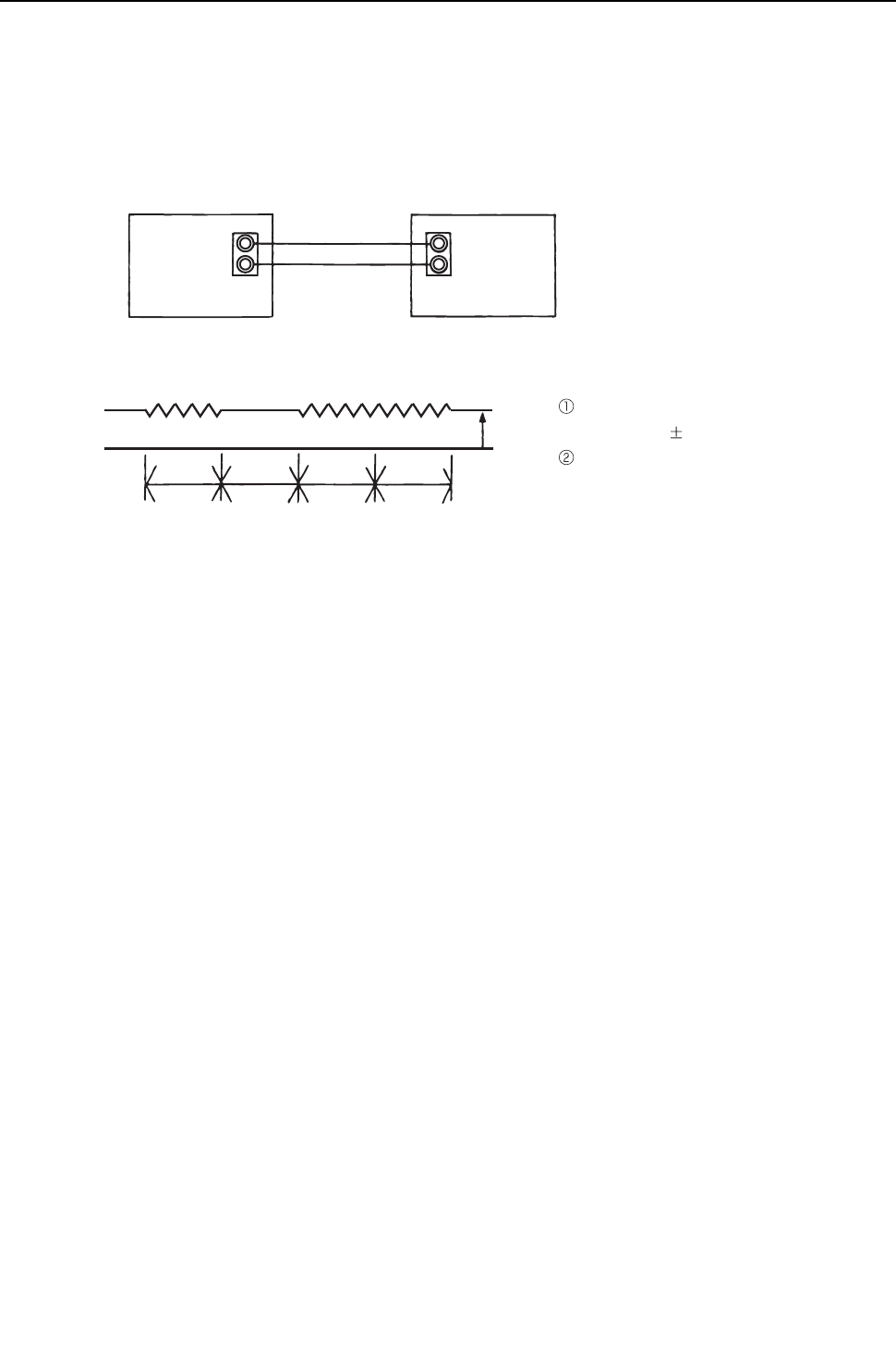
[ IX Troubleshooting ]
- 305 -
HWE09080 GB
2. MA remote controller transmission
The communication between the MA remote controller and the indoor unit is performed with current tone burst.
(1) Symptoms caused by noise interference on the transmission line
If noise is generated on the transmission line, and the communication between the MA remote controller and the indoor unit
is interrupted for 3 minutes in a row, MA transmission error (6831) will occur.
(2) Confirmation of transmission specifications and wave pattern
A, B : No polarity
Across terminal No. 1-2
: Power supply (9V to 12VDC)
Satisfies the formula
12 msec/bit 5%
Voltage among terminals must
be between DC9 and 12 V.
TB15
A
B
1
2
MA remote controller
Transmission waveform (Across terminal No.1 - 2)
DC9~12V
Logic 1 Logic 0 Logic 1 Logic 1
12msec 12msec 12msec 12msec
Indoor unit
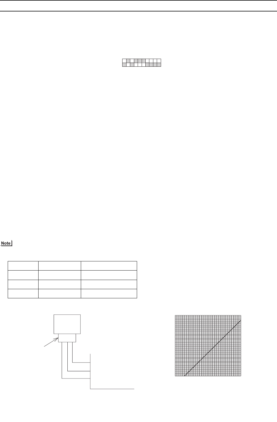
[ IX Troubleshooting ]
- 306 -
HWE09080 GB
[4] Troubleshooting Principal Parts
-1- High-Pressure Sensor (63HS1, PS1, PS3)
1. Compare the pressure that is detected by the high pressure sensor, and the high-pressure gauge pressure to check
for failure.
By configuring the digital display setting switch (SW1) as shown in the figure below, the pressure as measured by the high-
pressure sensor appears on the LED1 on the control board.
(1) While the sensor is stopped, compare the gauge pressure and the pressure displayed on self-diagnosis LED1.
1) When the gauge pressure is between 0 and 0.098MPa [14psi], internal pressure is caused due to gas leak.
2) When the pressure displayed on self-diagnosis LED1 is between 0 and 0.098MPa [14psi], the connector may be defective or
be disconnected. Check the connector and go to (4).
3) When the pressure displayed on self-diagnosis LED1 exceeds 4.15MPa [601psi], go to (3).
4) If other than 1), 2) or 3), compare the pressures while the sensor is running. Go to (2).
(2) Compare the gauge pressure and the pressure displayed on self-diagnosis LED1 while the sensor is running. (Com-
pare them by MPa [psi] unit.)
1) When the difference between both pressures is within 0.098MPa [14psi], both the high pressure sensor and the control board
are normal.
2) When the difference between both pressures exceeds 0.098MPa [14psi], the high pressure sensor has a problem. (perfor-
mance deterioration)
3) When the pressure displayed on self-diagnosis LED1 does not change, the high pressure sensor has a problem.
(3) Remove the high pressure sensor from the control board to check the pressure on the self-diagnosis LED1.
1) When the pressure displayed on self-diagnosis LED1 is between 0 and 0.098MPa [14psi], the high pressure sensor has a
problem.
2) When the pressure displayed on self-diagnosis LED1 is approximately 4.15MPa [601psi], the control board has a problem.
(4) Remove the high pressure sensor from the control board, and short-circuit between the No.2 and 3 connectors
(63HS1, PS1, PS3) to check the pressure with self-diagnosis LED1.
1) When the pressure displayed on the self-diagnosis LED1 exceeds 4.15MPa [601psi], the high pressure sensor has a problem.
2) If other than 1), the control board has a problem.
2. Pressure sensor configuration
The high pressure sensor consists of the circuit shown in the figure below. If DC 5V is applied between the red and the black
wires, voltage corresponding to the pressure between the white and the black wires will be output, and the value of this voltage
will be converted by the microcomputer. The output voltage is 0.071V per 0.098MPa [14psi].
The pressure sensor on the body side is designed to connect to the connector. The connector pin number on the body side
is different from that on the control board side.
Body side Control board side
Vcc Pin 1 Pin 3
Vout Pin 2 Pin 2
GND Pin 3 Pin 1
12345678910
ON
SW1
0
0.5 [73]
1.0 [145]
1.5 [218]
2.0 [290]
2.5 [363]
3.0 [435]
3.5 [508]
4.0 [580]
4.5 [653]
0 0.5 1 1.5 2 2.5 3 3.5
Output voltage (
V)
Pressure (
MPa [psi])
Connector
63HS1
1 2 3
1
2
3
GND (Black)
Vout (White)
Vcc (DC 5 V)(Red)
Pressure 0 ~ 4.15 MPa [601psi]
Vout 0.5 ~ 3.5 V
0.071 V / 0.098 MPa [14 psi]
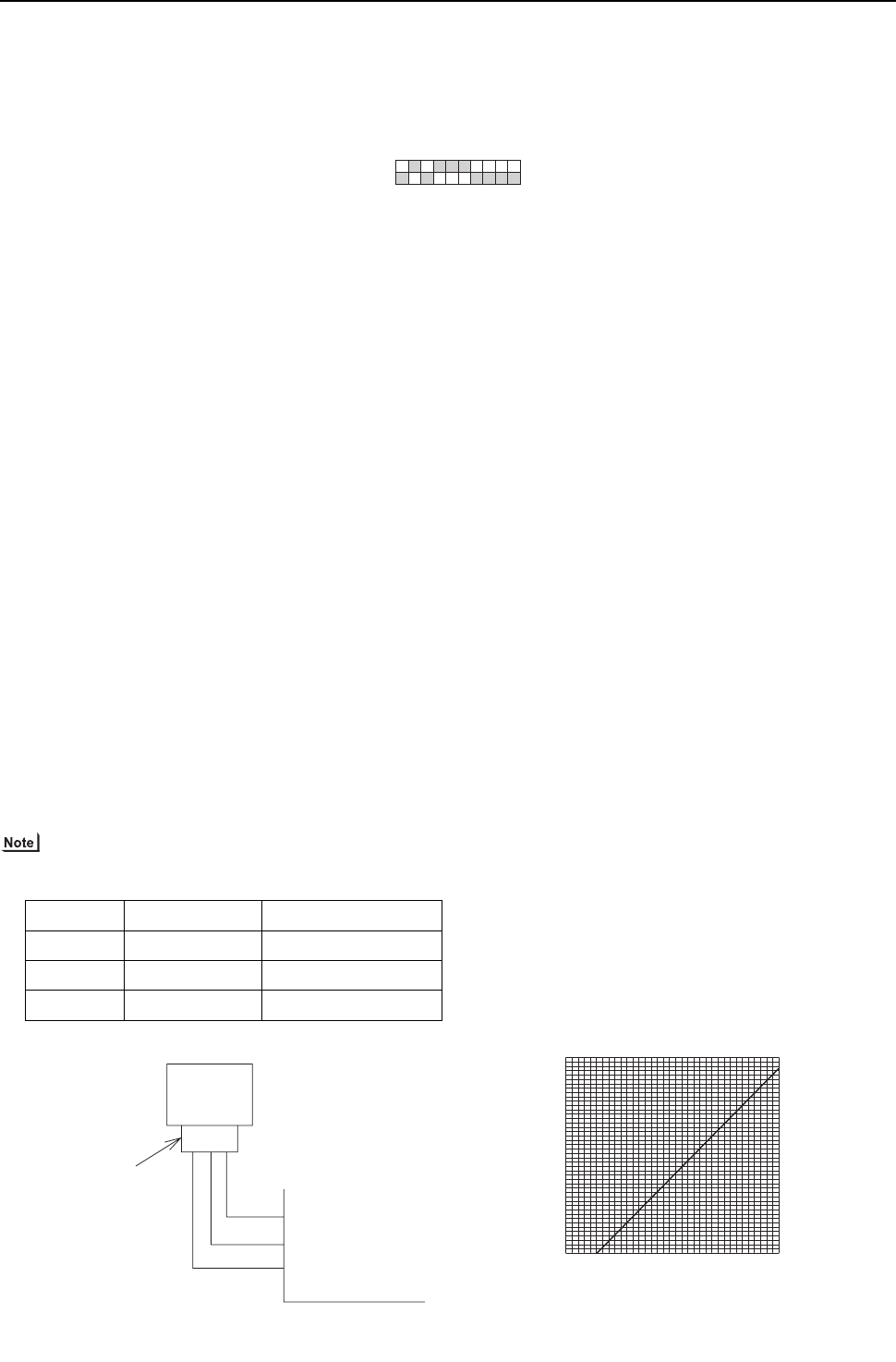
[ IX Troubleshooting ]
- 307 -
HWE09080 GB
-2- Low-Pressure Sensor (63LS)
1. Compare the pressure that is detected by the low pressure sensor, and the low pressure gauge pressure to check
for failure.
By configuring the digital display setting switch (SW1) as shown in the figure below, the pressure as measured by the low-
pressure sensor appears on the LED1 on the control board.
(1) While the sensor is stopped, compare the gauge pressure and the pressure displayed on self-diagnosis LED1.
1) When the gauge pressure is between 0 and 0.098MPa [14psi], internal pressure is caused due to gas leak.
2) When the pressure displayed on self-diagnosis LED1 is between 0 and 0.098MPa [14psi], the connector may be defective or
be disconnected. Check the connector and go to (4).
3) When the pressure displayed on self-diagnosis LED1 exceeds 1.7MPa [247psi], go to (3).
4) If other than 1), 2) or 3), compare the pressures while the sensor is running. Go to (2).
(2) Compare the gauge pressure and the pressure displayed on self-diagnosis LED1 while the sensor is running.(Com-
pare them by MPa [psi] unit.)
1) When the difference between both pressures is within 0.03MPa [4psi], both the low pressure sensor and the control board are
normal.
2) When the difference between both pressures exceeds 0.03MPa [4psi], the low pressure sensor has a problem. (performance
deterioration)
3) When the pressure displayed on the self-diagnosis LED1 does not change, the low pressure sensor has a problem.
(3) Remove the low pressure sensor from the control board to check the pressure with the self-diagnosis LED1 display.
1) When the pressure displayed on the self-diagnosis LED1 is between 0 and 0.098MPa [14psi], the low pressure sensor has a
problem.
2) When the pressure displayed on self-diagnosis LED1 is approximately 1.7MPa [247psi], the control board has a problem.
When the heat source temperature is 30°C [86°F] or less, the control board has a problem.
When the heat source temperature exceeds 30°C [86°F], go to (5).
(4) Remove the low pressure sensor from the control board, and short-circuit between the No.2 and 3 connectors
(63LS:CN202) to check the pressure with the self-diagnosis LED1.
1) When the pressure displayed on the self-diagnosis LED1 exceeds 1.7MPa [247psi], the low pressure sensor has a problem.
2) If other than 1), the control board has a problem.
(5) Remove the high pressure sensor (63HS1) from the control board, and insert it into the connector for the low pres-
sure sensor (63LS) to check the pressure with the self-diagnosis LED1.
1) When the pressure displayed on the self-diagnosis LED1 exceeds 1.7MPa [247psi], the control board has a problem.
2) If other than 1), the control board has a problem.
2. Low-pressure sensor configuration
The low pressure sensor consists of the circuit shown in the figure below. If DC5V is applied between the red and the black
wires, voltage corresponding to the pressure between the white and the black wires will be output, and the value of this voltage
will be converted by the microcomputer. The output voltage is 0.173V per 0.098MPa [14psi].
The pressure sensor on the body side is designed to connect to the connector. The connector pin number on the body side
is different from that on the control board side.
Body side Control board side
Vcc Pin 1 Pin 3
Vout Pin 2 Pin 2
GND Pin 3 Pin 1
12345678910
ON
SW1
0
0.2 [29]
0.4 [58]
0.6 [87]
0.8 [116]
1.0 [145]
1.2 [174]
1.4 [203]
1.6 [232]
1.8 [261]
0 0.5 1 1.5 2 2.5 3 3.5
Output voltage (
V)
Pressure (
MPa [psi])
Connector
63LS
1 2 3
1
2
3
GND (Black)
Vout (White)
Vcc (DC 5 V)(Red)
Pressure 0 ~ 1.7 MPa [247psi]
Vout 0.5 ~ 3.5 V
0.173 V / 0.098 MPa [14 psi]
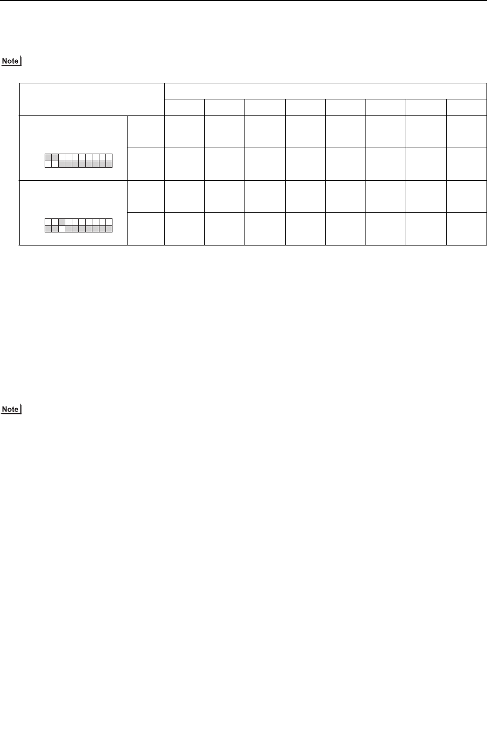
[ IX Troubleshooting ]
- 308 -
HWE09080 GB
-3- Solenoid Valve
Check whether the output signal from the control board and the operation of the solenoid valve match.
Setting the self-diagnosis switch (SW1) as shown in the figure below causes the ON signal of each relay to be output to the LED's.
Each LED shows whether the relays for the following parts are ON or OFF. LEDs light up when relays are on.
The circuits on some parts are closed when the relays are ON. Refer to the following instructions.
When a valve malfunctions, check if the wrong solenoid valve coil is not attached the lead wire of the coil is not disconnected, the
connector on the board is not inserted wrongly, or the wire for the connector is not disconnected.
(1) In case of 21S4a (4-way switching valve)
About this 4-way valve
When not powered:
Conducts electricity between the oil separator outlet and heat exchanger AND the gas ball valve (BV1) and the accumulator
to complete the circuit for the cooling cycle.
When powered:
The electricity runs between the oil separator and the gas ball valve, and between the heat exchanger and the accumulator.
This circulation is for heating.
Check the LED display and the intake and the discharge temperature for the 4-way valve to check whether the valve has no
faults and the electricity runs between where and where.Do not touch the pipe when checking the temperature, as the pipe
on the oil separator side will be hot.
Do not give an impact from outside, as the outer hull will be deformed leading to the malfunction of the inner valve.
(2) In case of SV1a (Bypass valve)
This solenoid valve opens when powered (Relay ON).
1) At compressor start-up, the SV1a turns on for 4 minutes, and the operation can be checked by the self-diagnosis LED display
and the closing sound.
2) To check whether the valve is open or closed, check the change of the SV1a downstream piping temperature while the valve
is being powered.Even when the valve is closed, high-temperature refrigerant flows inside the capillary next to the valve.
(Therefore, temperature of the downstream piping will not be low with the valve closed.)
(3) SV4a - 4d, SV7a, 7b(Controls heat exchanger capacity)
1) At least one of the solenoid valves among SV4a through 4d,SV7a, and SV7b turns on. Check for proper operation on the LED
and by listening for the operation sound of the solenoid valve.
2) This diagram shows the flow of the high-temperature (high-pressure) gas refrigerant in the Cooling-only and Cooling-main
modes and the flow of the low-temperature gas/liquid refrigerant in the Heating-only and Heating-main modes. Refer to the
refrigerant circuit diagram. Solenoid valves turns on and off according to such factors as the capacity of the indoor units in
operation and water inlet temperature. Check the LED. Remove the SV coil, open the lid, and check the plunger. The type of
pin face wrench that is listed in the service parts list is required to perform this task.
SW1
Display
LD1 LD2 LD3 LD4 LD5 LD6 LD7 LD8
Upper 21S4a CH11 SV1a
Lower
Upper SV4a SV4b SV4d SV9
Lower SV7a SV7b
12345678910
ON
SW1
12345678 9 10
ON
SW1
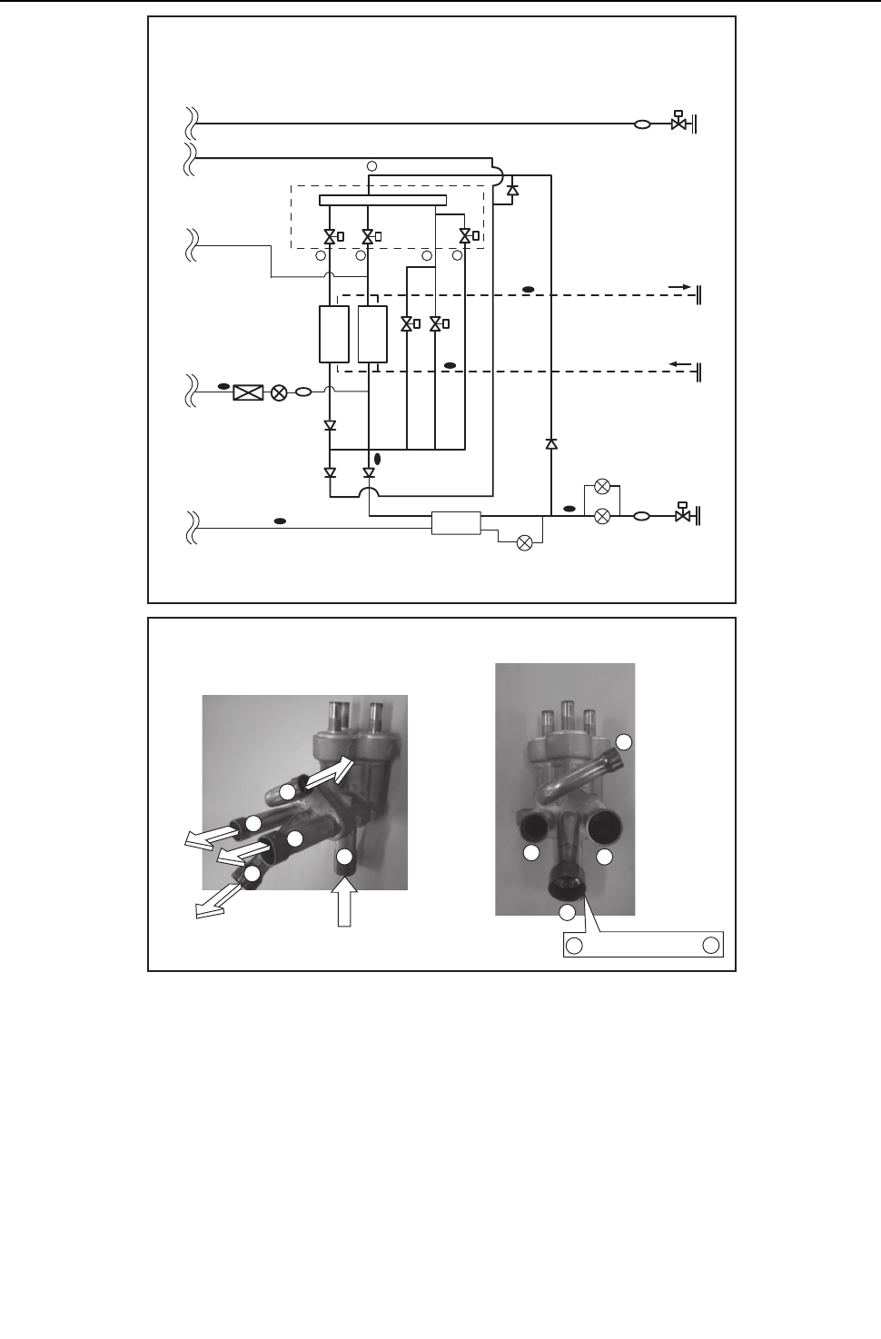
[ IX Troubleshooting ]
- 309 -
HWE09080 GB
Refrigerant Circuit diagram <PQHY>
1
2
3
4
5
1
2 3 45
2
3
4
5
Solenoid valve block(three compartments)
1 is located behind 3
TH3
CV8
CV6a
TH8
TH7
SV7bSV7a
CV4a
CV3a
CV7a
BV2
SV4a SV4b
SV4d
Solenoid valve block
THINV
Component cooler
heat exchanger
LEVINV
ST13
Water circuit
ST2
LEV1
HIC
TH2
TH6
LEV2a
LEV2b
BV1
ST1
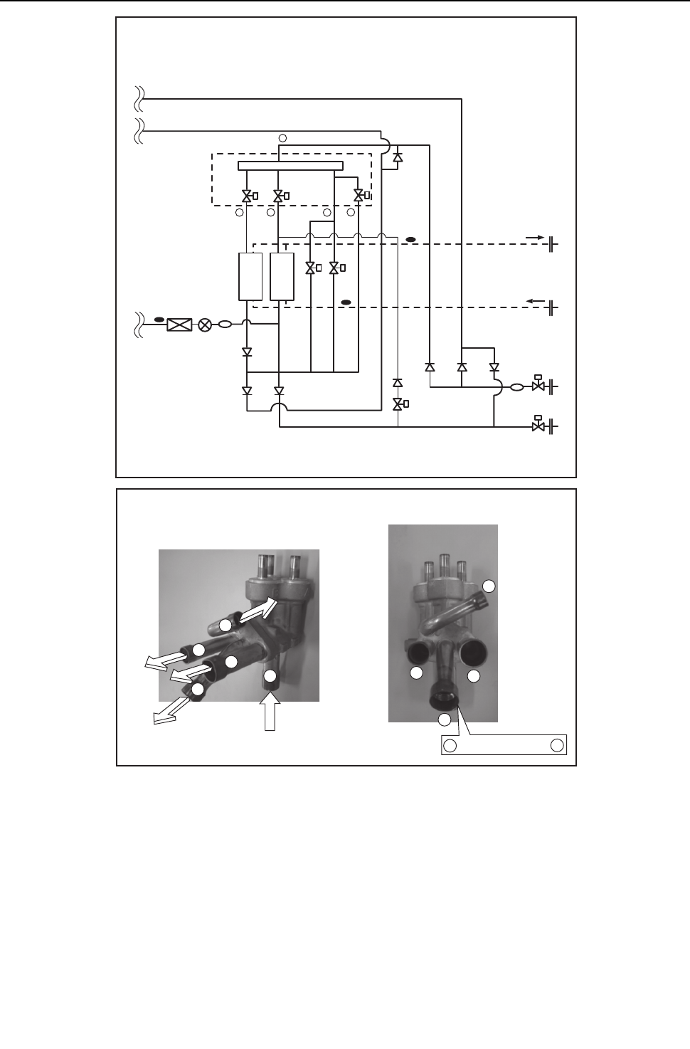
[ IX Troubleshooting ]
- 310 -
HWE09080 GB
(4) In the case of SV9 (Bypass valve)
This solenoid valve opens when energized (when the relay is on)
This valve turns on when the value of 63HS1 is greater than 3.5 MPa [507psi] during Heating-only or Heating-main operation
at the minimum frequency. The valve position can be determined by measuring and monitoring the changes in the pipe tem-
perature on the downstream of SV9 while the unit is energized. When the valve is open, high-temperature gas refrigerant
passes through the pipe. Do not attempt to check the pipe temperature by touching the pipe.
-4- LEV
LEV operation
LEV (Indoor unit: Linear expansion valve), LEV2a, and LEV2b (Heat source unit: Linear expansion valve) are stepping-motor-
driven valves that operate by receiving the pulse signals from the indoor and heat source unit control boards.
(1) Indoor LEV and Heat source LEV (LEV2a, LEV2b)
The valve opening changes according to the number of pulses.
1) Indoor and heat source unit control boards and the LEV (Indoor unit: Linear expansion valve)
1
2
3
4
5
2
3
4
5
Solenoid valve block(three compartments)
1 is located behind 3
Refrigerant Circuit diagram <PQRY>
1
2 3 45
ST1
BV1
BV2
Water circuit
CV8
CV6a
TH8
TH7
SV7bSV7a
SV9
CV4a
CV2aCV3a
CV7a
CV5a
SV4a SV4b
SV4d
Solenoid valve block
THINV
Component cooler
heat exchanger
LEVINV
ST13
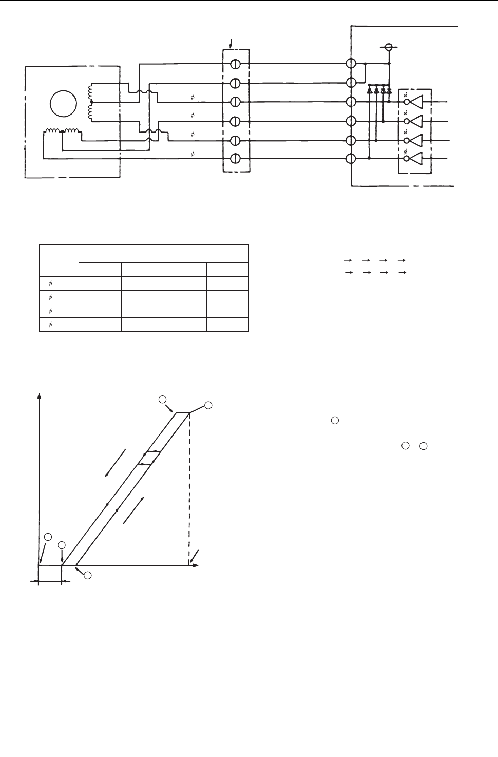
[ IX Troubleshooting ]
- 311 -
HWE09080 GB
2) Pulse signal output and valve operation
3) LEV valve closing and opening operation
Note. The connector numbers on the intermediate connector and the connector on the control board differ. Check the color of the lead wire
to judge the number.
Heat source control board
Drive circuit
LEV
M
5
5
2
2
1
1
3
3
4
4
6
6
DC12V
Red
Intermediate connector
Brown
Blue
Orange
Yellow
White
Red Orange
White
Brown
Blue
Yellow
6
5
4 4
3
2
1
3
2
1
4
3
2
1
Output state
Output
(phase)
number
1234
1 ON OFF OFF ON
2 ON ON OFF OFF
3 OFF ON ON OFF
4 OFF OFF ON ON
Output pulses change in the following orders when the
Valve is closed; 1 2 3 4 1
Valve is open;
4 3 2 1 4
*1. When the LEV opening angle does not change,
all the output phases will be off.
*2. When the output is open phase or remains ON,
the motor cannot run smoothly, and rattles and vibrates.
*When the power is turned on, the valve closing signal of 2200 pulses
will be output from the indoor board to LEV to fix the valve position.
It must be fixed at point A.
When the valve operates smoothly, no sound from LEV or no vibration
occurs, however, when the pulses change from E to A in the chart or
the valve is locked, a big sound occurs.
*Whether a sound is generated or not can be determined by
holding a screwdriver against it, then placing your ear against the handle.
Valve opening (refrigerant flow rate)
Valve closed
Valve open
E
B
80 - 100 pulses
Pulses
Fully open: 1400 pulses
A
C
D
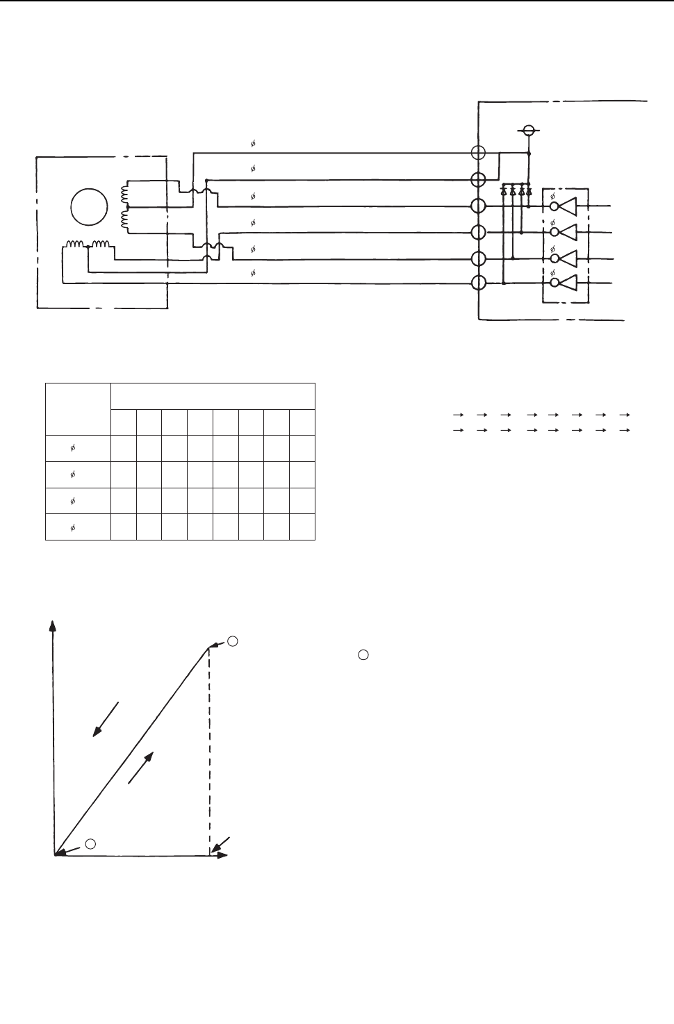
[ IX Troubleshooting ]
- 312 -
HWE09080 GB
(2) Heat source LEV (LEV1,LEVINV)
The valve opening changes according to the number of pulses.
1) Connections between the heat source control board and LEV
2) Pulse signal output and valve operation
3) LEV valve closing and opening operation
LEV
DC 12V
Heat source control board
M
4
6
2
3
5
1
4
5
6
3
2
1
4
5
6
3
2
1
4
3
2
1
Red
Brown
Blue
Orange
Yellow
White
Drive circuit
12345678
1 ON OFF OFF OFF OFF OFF ON ON
2 ON ON ON OFF OFF OFF OFF OFF
3 OFF OFF ON ON ON OFF OFF OFF
4 OFF OFF OFF OFF ON ON ON OFF
Output pulses change in the following orders when the
Valve is open; 1 2 3 4 5 6 7 8 1
Valve is closed;
8
7 6 5 4 3 2 1 8
*1. When the LEV opening angle does not change,
all the output phases will be off.
*2. When the output is open phase or remains ON,
the motor cannot run smoothly, and rattles and vibrates.
Output
(phase)
number
Output state
*When the power is turned on, the valve closing signal of 520 pulses
will be output from the indoor board to LEV to fix the valve position.
It must be fixed at point A.
(Pulse signal is output for approximately 17 seconds.)
When the valve operates smoothly, there is no sound from the LEV and no
vibration occurs, but when the valve is locked, noise is generated.
*Whether a sound is generated or not can be determined by
holding a screwdriver against it, then placing your ear against the handle.
*If liquid refrigerant flows inside the LEV, the sound may become smaller.
B
A
Fully open: 480 pulses
Pulses
Valve opening (refrigerant flow rate)
Valve closed
Valve open
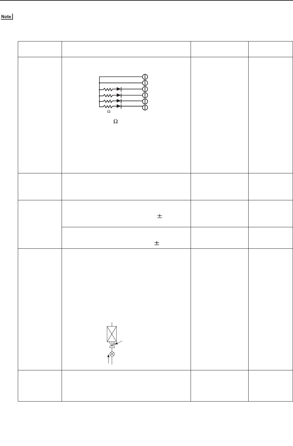
[ IX Troubleshooting ]
- 313 -
HWE09080 GB
(3) Judgment methods and possible failure mode
The specifications of the heat source unit (heat source LEV), indoor unit (indoor LEV),and BC controller (BC controller LEV)
differ.Therefore, remedies for each failure may vary. Check the remedy specified for the appropriate LEV as indicated in the
right column.
Malfunction
mode
Judgment method Remedy Target LEV
Microcomputer
driver circuit fail-
ure
Disconnect the control board connector and connect
the check LED as shown in the figure below.
resistance : 0.25W 1k
LED : DC15V 20mA or more
When the main power is turned on, the indoor unit cir-
cuit board outputs pulse signals to the indoor unit LEV
for 10 seconds, and the heat source unit circuit board
outputs pulse signals to the heat source unit LEV for 17
seconds.
If any of the LED remains lit or unlit, the drive circuit is
faulty.
When the drive circuit
has a problem, replace
the control board.
Indoor
Heat source
LEV mechanism
is locked
If the LEV is locked, the drive motor runs idle, and
makes a small clicking sound.
When the valve makes a closing and opening sound,
the valve has a problem.
Replace the LEV. Indoor
Heat source
BC controller
Disconnected or
short-circuited
LEV motor coil
Measure resistance between the coils (red - white, red
-orange, brown - yellow, brown - blue) using a tester.
They are normal if resistance is 150ohm 10%.
Replace the LEV coils. Indoor
Heat source
(LEV2a,LEV2b)
BC controller
Measure resistance between the coils (red - white, red
-orange, brown - yellow, brown - blue) using a tester.
They are normal if resistance is 46ohm 3%.
Replace the LEV coils. Heat source
(LEV1,LEVINV)
Incomple sealing
(leak from the
valve)
When checking the refrigerant leak from the indoor
LEV, run the target indoor unit in the fan mode, and the
other indoor units in the cooling mode. Then, check the
liquid temperature (TH22) with the self-diagnosis LED.
When the unit is running in the fan mode, the LEV is ful-
ly closed, and the temperature detected by the thermis-
tor is not low. If there is a leak, however, the
temperature will be low. If the temperature is extremely
low compared with the inlet temperature displayed on
the remote controller, the LEV is not properly sealed,
however, if there is a little leak, it is not necessary to re-
place the LEV when there are no effects to other parts.
If there is a large
amount of leakage, re-
place the LEV.
Indoor
BC controller
Faulty wire con-
nections in the
connector or
faulty contact
1. Check for loose pins on the connector and check
the colors of the lead wires visually
Check the continuity at
the points where an er-
ror occurs.
Indoor
Heat source
BC controller
2. Disconnect the control board's connector and
conduct a continuity check using a tester.
6
5
4
3
2
1
1 k
LED
Thermistor
(liquid piping
temperature detection)
Linear Expansion Valve
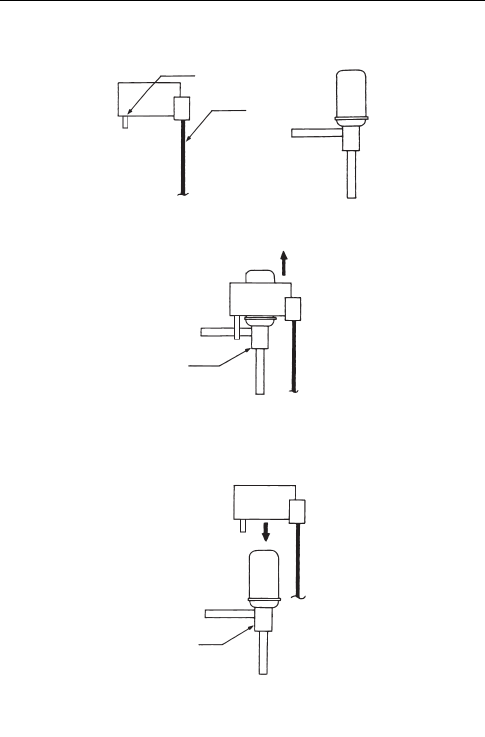
[ IX Troubleshooting ]
- 314 -
HWE09080 GB
(4) Heat source unit LEV (LEV1,LEVINV) coil removal procedure
1) LEV component
As shown in the figure, the heat source LEV is made in such a way that the coils and the body can be separated.
2) Removing the coils
Fasten the body tightly at the bottom (Part A in the figure) so that the body will not move, then pull out the coils toward the
top.If the coils are pulled out without the body gripped, undue force will be applied and the pipe will be bent.
3) Installing the coils
Fix the body tightly at the bottom (Part A in the figure) so that the body will not move, then insert the coils from the top, and
insert the coil stopper securely in the pipe on the body. Hold the body when pulling out the coils to prevent so that the pipe
will not be bent.
If the coils are pushed without the body gripped, undue force will be applied and the pipe will be bent. Hold the body when
pulling out the coils to prevent so that the pipe will not be bent.
Coils Stopper
Lead wire
Body
Part A
Part A
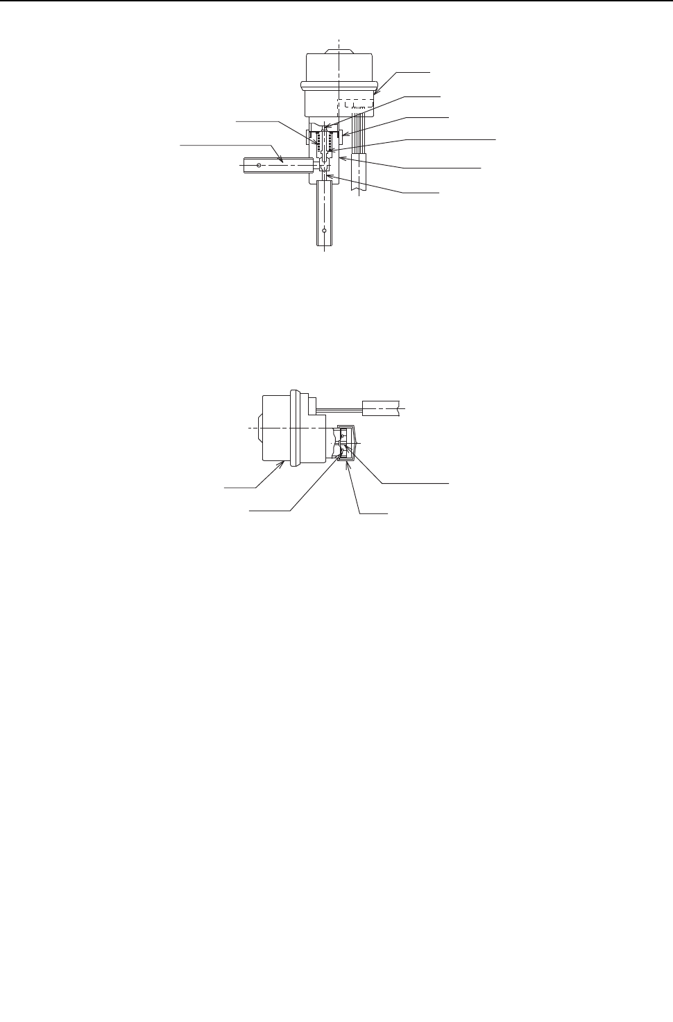
[ IX Troubleshooting ]
- 315 -
HWE09080 GB
(5) Heat source unit LEV (LEV2a,2b) coil removal procedure
Notes on the procedure
1) Do not put undue pressure on the motor.
2) Do not use motors if dropped.
3) Do not remove the cap until immediately before the procedure.
4) Do not wipe off any molybdenum.
5) Do not remove the packing.
6) Do not apply any other than specified liquid such as screw lock agent, grease and etc.
Motor
Driver
Locknut
Valve assembling
Valve body side
Orifice
Bellows
Refrigerant Circuit
Motor
Packing Cap
Molybdenum

[ IX Troubleshooting ]
- 316 -
HWE09080 GB
Replacement procedure
1) Stop the air conditioner. After checking that the air conditioner is stopped, turn off the power of the heat source unit.
2) Prepare two spanners. Hold the valve body with one spanner and loosen the locknut with another one.
Turning the locknut counter-clockwise from motor side view can loosen it.
Two spanners must be used.
Do not hold the motor with one hand and loosen the locknut with only one spanner.
3) Turning the locknut several times. The locknut will come off and then the motor can be removed.
4) Prepare a motor replacement. Use only factory settings, which the head part of the driver does not come out.Use of
other than factory settings may result in malfunction and failure of valve flow rate control.
5) Keep dust, contaminants, and water out of the space between the motor and the valve body during replacement. (The
space is the mechanical section of the valve.) Do not damage the junction with tools.
After removing the motor, blow N2 gas or etc. into bellows in order to blow off water from inside.
6) Remove the cap of the motor replacement. Joint the axis of the motor and the one of the valve body with the locknut to
stick precisely. Apply screw lock agent to whole part of the screw. Do not introduce screw lock agent into the
motor.Use new motors if problems are found on the motor during the replacement.
7) After rotating the locknut 2~3 times by hands, hold the valve body with the spanner, and tighten the locknut with the
specified torque with a torque wrench. Apply the tightening torque of 15N m (150kgf cm) (administration value
15 1 N m (150 10kgf cm)).
Note that undue tightening may cause breaking a flare nut.
8) When tightening the locknut, hold the motor with hands so that undue rotary torque and load can not be applied.
9) The differences of relative position after assembling the motor and the valve body do not affect the valve control and
the switching function.
Do not relocate the motor and the valve body after tightening the locknut. Even the relative position is different from
before and after assembling.
The motor may not be fixed with clamp because of the changing of the motor configuration. However, the fixing is not
necessary due to the pipe fixing.
10) Connect the connector. Do not pull hard on the lead wire. Make sure that the connector is securely inserted into the
specified position, and check that the connector does not come off easily.
11) Turn on the indoor unit, and operate the air conditioner. Check that no problems are found.
Difference in rotational direction is acceptable.
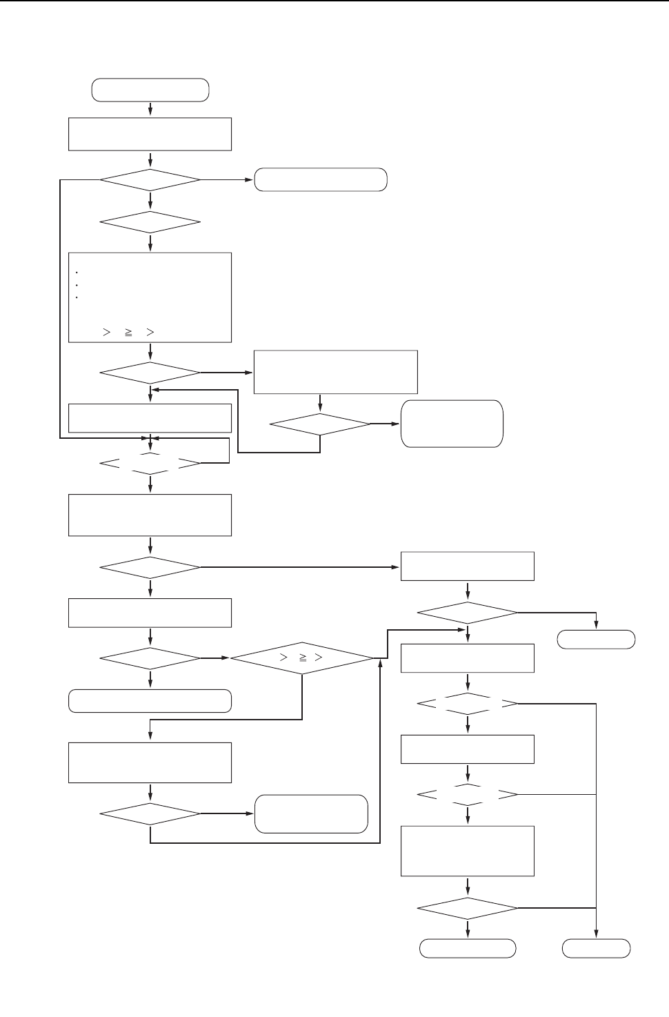
[ IX Troubleshooting ]
- 317 -
HWE09080 GB
-5- Troubleshooting Principal Parts of BC Controller
1. Pressure sensor
Troubleshooting flow chart for pressure sensor
Check whether the pressure sensor or the
connectors of P1 and P3 are connected,
properly
All the compressors of the heat source units to
which the BC controller is connected are stopped.
Check P1 and P3 on the self-diagnosis
LED, and check that the detected
pressure is 0.098MPa [14psi] or less.
On the self-diagnosis monitor, measure
Heat source high-pressure 63HS1
Heat source low-pressure 63LS
BC controller pressure P1 (liquid side)
and P3 (intermediate part)
Check whether the result is
63HS1 P1 P3 63LS
START
Repair the fault.
Fix the relation between
the refrigerant piping
and the transmission line.
Fix the relation between the
refrigerant piping and the
transmission line.
Replace the pressure sensor. Replace the board.
Restore contact failure.
Check whether the contact of the pressure
sensor connector in trouble is not faulty.
OK?
OK?
Check that the difference between each
detected pressure is 0.098MPa [14psi] or less.
OK?
Both the board and the pressure sensor are normal.
OK?
Is Pd P1 P3 Ps?
Remove the pressure sensor connector
from the board, and check the pressure.
OK?
OK?
Check whether the refrigerant pipe and the
transmission line are connected correctly between
the heat source unit and the BC controller.
OK?
Operating at the moment?
Check whether the refrigerant pipe
and the transmission line are
connected correctly between the heat
source unit and the BC controller.
OK?
YES
Note 2
Note 1
NO
YES
YES
YES
Note 3
Note 4
NO
NO
NO
NO
YES
NO
NO
YES
YES
YES
NO
NO
YES
NO
YES
NO
NO
Replace the pressure sensor, which detects
less than 6MPa [870psi] pressure, with the
pressure sensor, which detects 6MPa [870psi]
or more pressure, check the pressure, and
check whether the detected pressure is
displayed normally.
10 minutes or longer after
the operation stops?
Pressure 0MPa [0psi]
6MPa [870psi] pressure
or more is displayed.
Short-circuit between connecter pins #2 and #3
on the circuit board, and check the pressure.
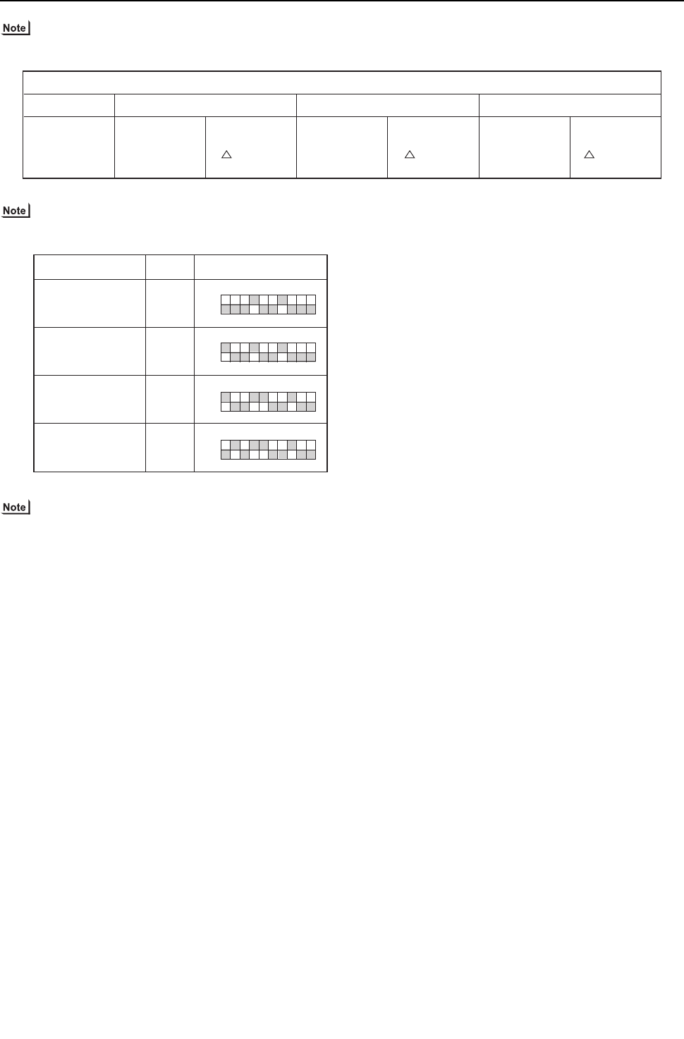
[ IX Troubleshooting ]
- 318 -
HWE09080 GB
1) BC controller: Phenomena when the pressure sensor is connected wrongly (reverse connection of P1 and P3) to the board.
2) Check the self-diagnosis switch (Heat source control board SW1).
3) Check whether CNP1 (liquid side) connector on the BC controller control board and the connector CNP2 (intermediate part)
are not disconnected or not loose.
4) Check the pressure value on the self-diagnosis switch (same as note 2) with the connector of the applied pressure sensor is
disconnected from the board.
Cooling-only Heating only
Heating main
Non-cooling
Indoor heating SC small
Heating indoor Thermo ON
Especially noise is large.
Indoor heating SC small
Heating indoor Thermo ON
Especially noise is large.
Cooling-main
Symptoms
SC11 large
SC16 small
PHM large
SC11 large
SC16 small
PHM large
Non-cooling Normal SC11 large
SC16 small
PHM large
Measurement data SW1 setting value
Heat source high pressure
Heat source low pressure
BC controller pressure
(liquid side)
BC controller pressure
(intermediate part)
Symbol
63HS1
PS1
63LS
PS3
12345678910
ON
12345678910
ON
12345678910
ON
12345678910
ON
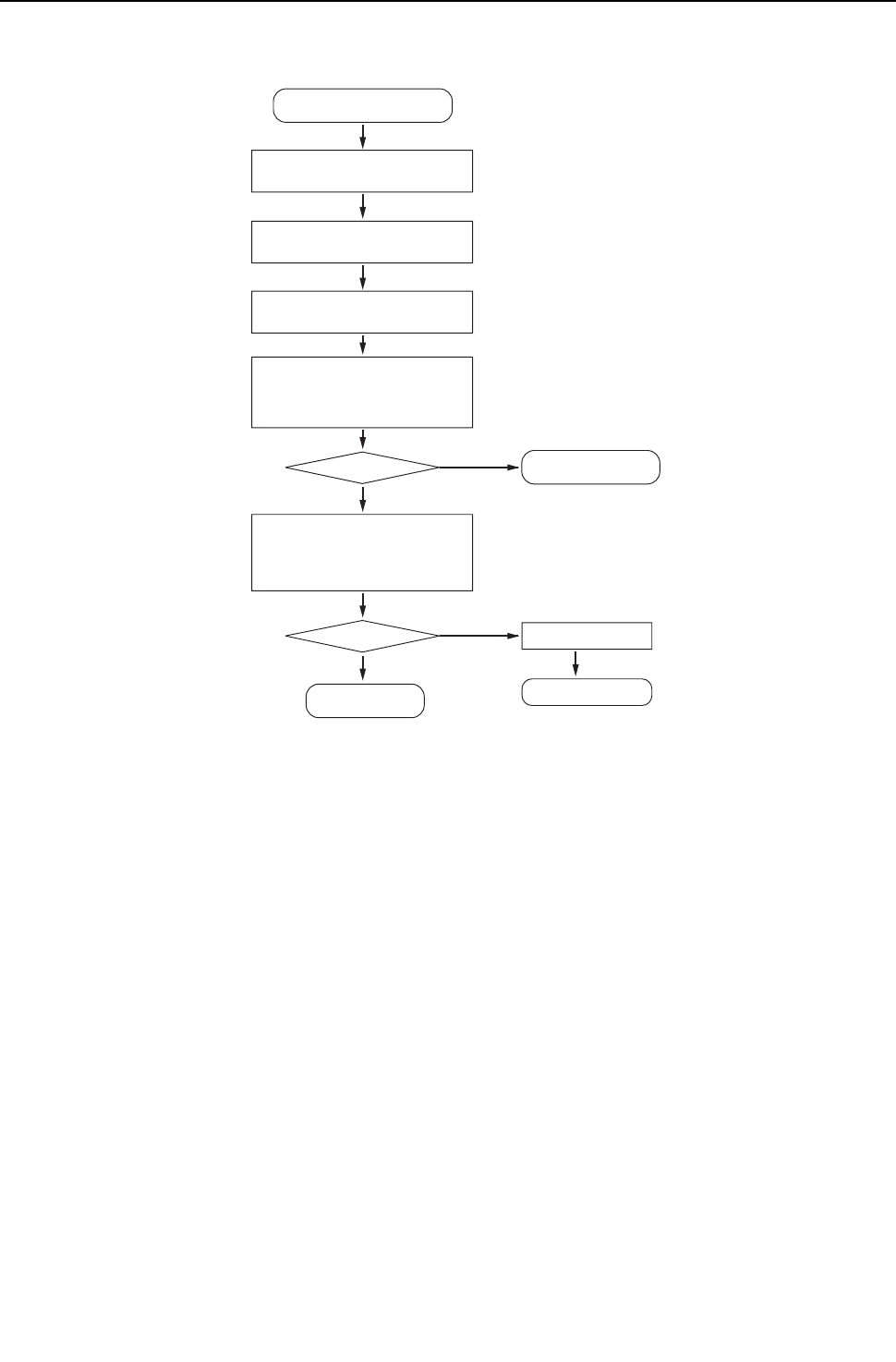
[ IX Troubleshooting ]
- 319 -
HWE09080 GB
2. Temperature sensor
Pull out the thermistor connector in
trouble from the board.
Measure the temperature of the thermistor
in trouble. (actual measurement value)
Check the thermistor resistor.
Compare the temperature corresponding to the
resistance measured by the thermistor and the
temperature measured by a commercially
available thermometer, and check whether
there is no difference between them.
Insert the connector of the thermistor
in trouble into the board, check the sensor
inlet temperature on the LED monitor,
and check the temperature difference.
START
Normal
Troubleshooting instructions for thermistor
Replace the thermistor
Temperature difference
Temperature difference
Check for contact failure.
Replace the control board.
Note 1
Note 2
Note 2
Note 3
YES
NO
YES
NO
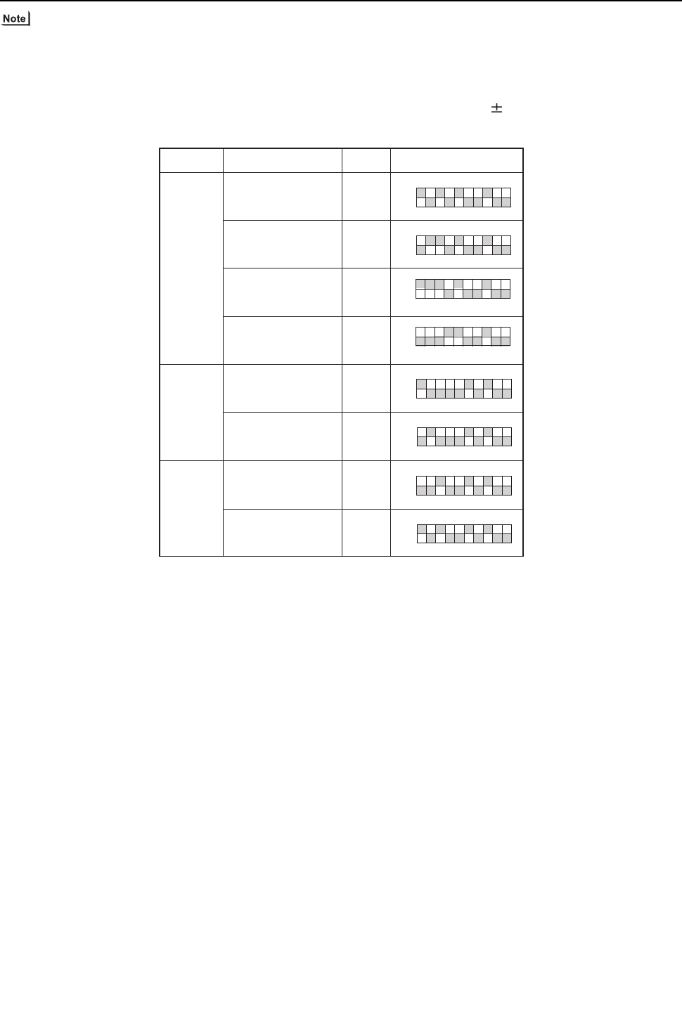
[ IX Troubleshooting ]
- 320 -
HWE09080 GB
1) For the connectors on the board, TH11 and TH12 are connected to CN10, and TH15 and TH16 are connected to CN11. Dis-
connect the connector in trouble, and check the sensor of each number.
2)
Pull out the sensor connector from the I/O board, Do not pull the sensor by holding the lead wire.
Measure the resistance with such as a tester.
Compare the measured value with that of shown in the figure below. When the result is 10%, it is normal.
3) Check the self-diagnosis switch (Heat source control board SW1).
12345678910
ON
12345678910
ON
12345678910
ON
12345678910
ON
12345678910
ON
12345678910
ON
12345678910
ON
12345678910
ON
TH12
TH15
TH12
TH15
Liquid inlet temperature
Bypass outlet temperature
Bypass outlet temperature
Bypass outlet temperature
TH11
TH12
Bypass inlet temperature
Bypass inlet temperature
Bypass inlet temperature
Bypass inlet temperature
TH15
TH16
Measurement data SW1 setting value Symbol
G, GA
(Standard / main)
GB, HB
(Sub 1)
GB, HB
(Sub 2)
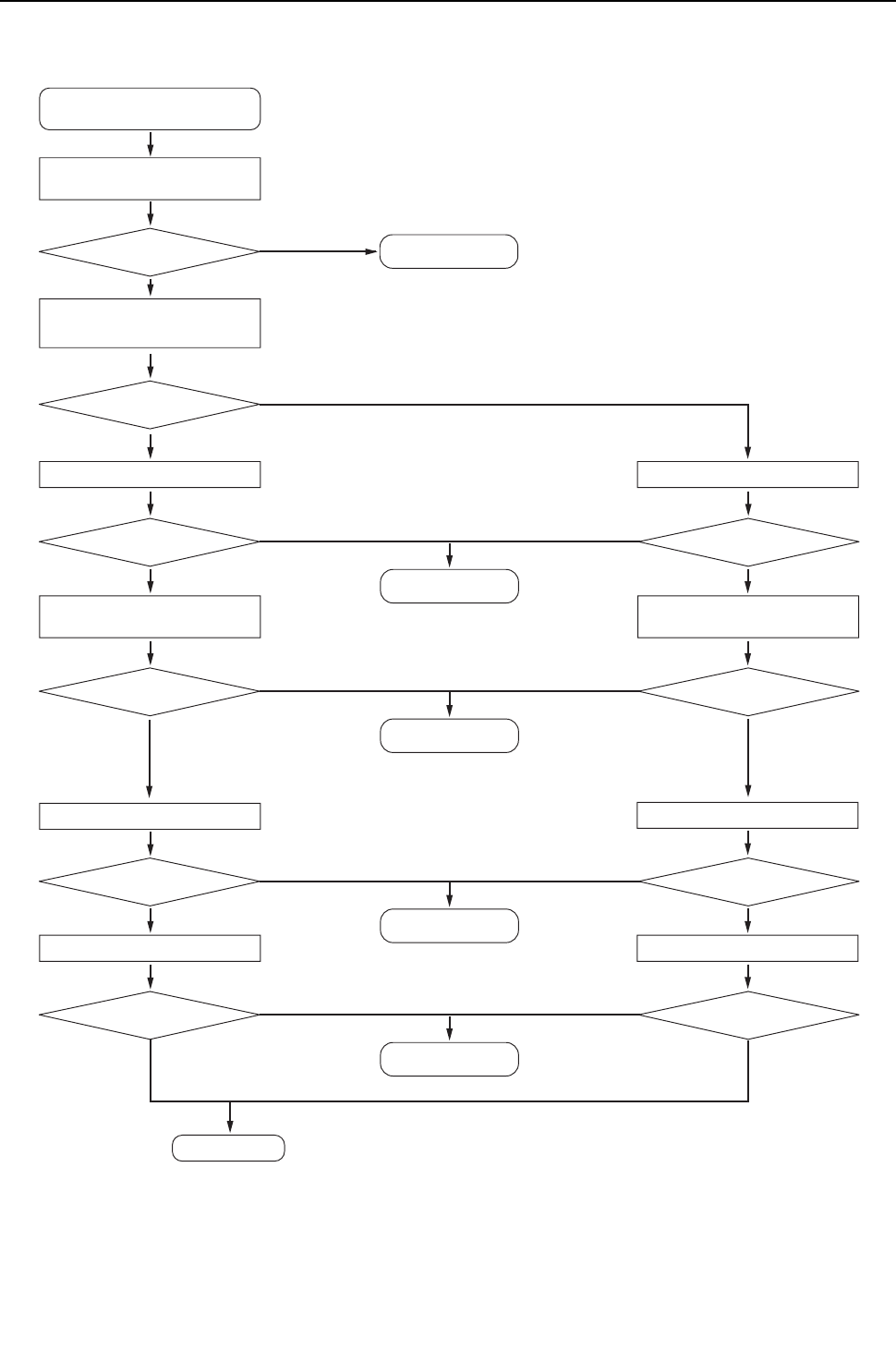
[ IX Troubleshooting ]
- 321 -
HWE09080 GB
3. Troubleshooting flow chart for LEV Solenoid valve
(1) LEV
Check whether the electric expansion
valve and the solenoid valve connector
are not disconnected or not loose.
Run the cooling operation or the heating
operation in the system in trouble
(only in one system).
No cooling capacity
No heating capacity
Repair the fault.
Fault is found.
Note 1
NO
Check that LEV1 is fully open. Check that LEV1 is fully open.
Check that SVA and SVC are ON.
Check that SVA and SVC are OFF.
Cooling or heating operation
Note 2
Heating operation
Check whether LEV3 is controlling
superheat.
Check LEV1.
Check LEV3.
Check SVA and SVC.
Check SVB.
LEV1 is fully open.
Check whether LEV 3 is controlled by
the value of the differential pressure.
LEV1 is fully open.
Note 3
Note 2
Note 3
YES
NO
Cooling operation
Superheat control OK Differential pressure OK
YES
NO
Check that SVB is OFF. Check that SVB is ON.
SVA, SVC ON SVA, SVC OFF
YES
YES
NO
Completed
SVB OFF SVB ON
YES
YES
YES
YES
NO
NO
NO
NO
NO
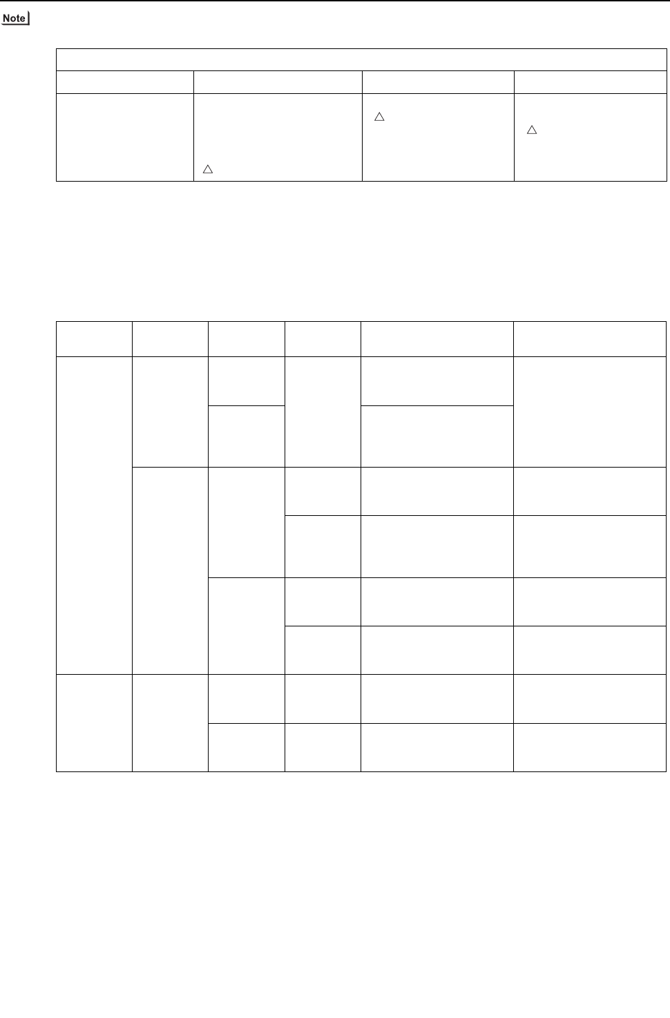
[ IX Troubleshooting ]
- 322 -
HWE09080 GB
1) BC controller: Phenomena when LEV is connected wrongly (reverse connection of LEV1 and LEV3) to the board.
2) Check method of fully open state or fully closed state of LEV
Check LEV opening (pulse) on the self-diagnosis LED (Heat source control board SW1).
Full open: 2000 pulses
Fully closed: 110 pulses (In the case of heating-only mode, however, the pulse may become 110 or more.)
When LEV is fully open, measure the temperature at the upstream and downstream pipes of LEV, and make sure that there
is no temperature difference.
When LEV is fully closed, check that there is no refrigerant flowing sound.
3) Refer to the chart below to judge LEV opening controlled by the values of the differential pressure and of the superheat.
(BC controller LEV basic operation characteristic)
Phenomena
Cooling-only Cooling-main Heating only Heating main
Non-cooling
SH12 small, SC11 small
SH16 small, branch pipe
SC small
BC controller sound
Non-cooling and non-heating
SH12 small, SC11 small
SH16 large, but branch pipe
SC small
BC controller sound
PHM large
Indoor heating SC small
PHM large
Non-cooling
Indoor heating SC small
PHM large
Part Malfunction
mode
Operation
mode Content Standards of judgment on
unit stable operation
G, GA
type
LEV1
Inclined to
close Heating only
Heating-
main
Cooling-
main
Difference between high
pressure (P1) and interme-
diate pressure (P3) is large.
0.3 to 0.4MPa
[44 to 58psi]
Inclined to
open
Difference between high
pressure (P1) and interme-
diate pressure (P3) is
small.
LEV3
Inclined to
close
Cooling-only
Cooling-
main
SH12 is large. SH12 < 20°C [36°F]
Heating only
Heating-
main
Difference between high
pressure (P1) and interme-
diate pressure (P3) is
small.
0.3 to 0.4MPa
[44 to 58psi]
Inclined to
open
Cooling-only
Cooling-
main
SC16 and SH12 are small. SC16 > 3°C [5.4°F]
SH12 > 3°C [5.4°F]
Heating only
Heating-
main
Difference between high
pressure (P1) and interme-
diate pressure (P3) is large.
0.3 to 0.4MPa
[44 to 58psi]
GB, HB type LEV3
Inclined to
close
Cooling-only
Cooling-
main
SH22 is large. SH22 < 20°C [36°F]
Inclined to
open
Cooling-only
Cooling-
main
SH22 is small. SH22 > 3°C [5.4°F]
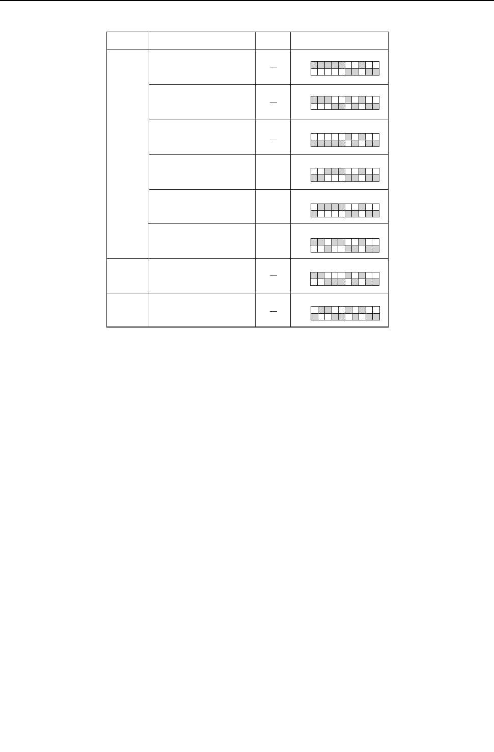
[ IX Troubleshooting ]
- 323 -
HWE09080 GB
Self-diagnosis LED
12345678910
ON
12345678910
ON
12345678910
ON
12345678910
ON
12345678910
ON
12345678910
ON
12345678910
ON
12345678910
ON
LEV1 opening
LEV3 opening
LEV3 opening
BC controller bypass
outlet superheat
BC controller intermediate
part subcool
SH12
LEV2 opening
LEV3 opening
SC16
BC controller liquid-side subcool
SC11
Measurement data SW1 setting value Symbol
G, GA
(Standard
/ main)
GB, HB
(Sub 1)
GB, HB
(Sub 2)
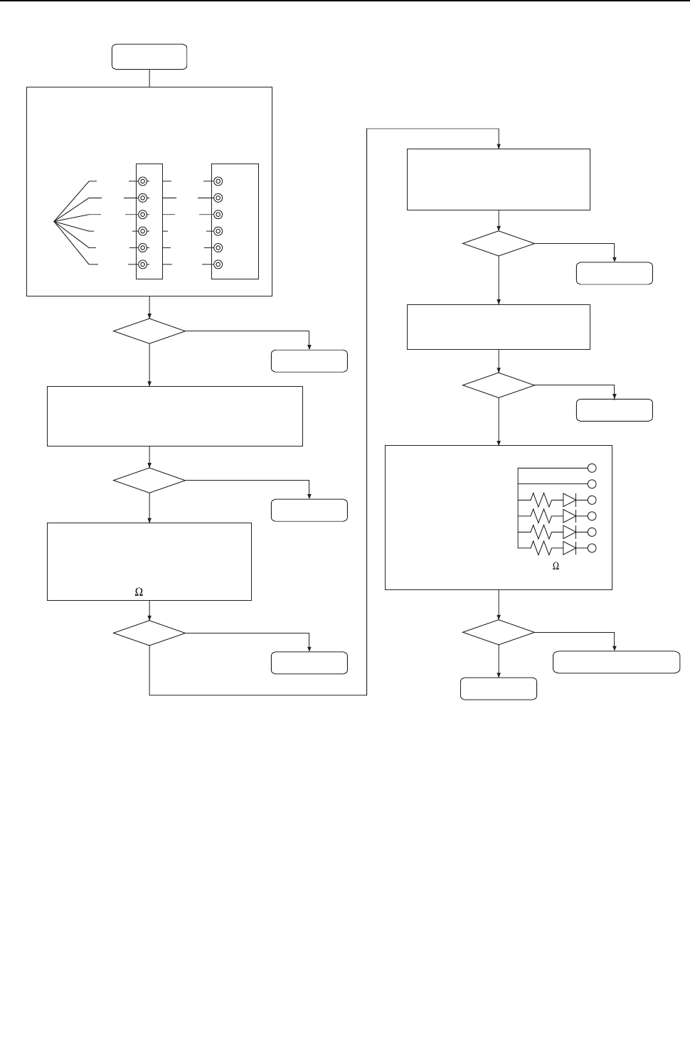
[ IX Troubleshooting ]
- 324 -
HWE09080 GB
Troubleshooting flow chart for solenoid valve body
6
6
5
4
3
2
1
5
4
3
2
1
2
5
1
3
4
6
To
LEV
LED10 k
Start
Brown
Red
Blue
Orange
Yellow
White
Brown
Red
Blue
Orange
Yellow
White
OK? NO
YES
OK? NO
YES
Repair the fault.
Repair the fault.
OK? NO
YES
OK? NO
YES
Replace LEV.
OK? NO
YES
Replace LEV.
Replace LEV.
OK? NO
YES
Replace the board in trouble.
Completed
Check for pins not fully inserted on the connector
and check the colors of the lead wires visually.
Intermediate connector
Control board
Check that no refrigerant
leaks from LEV.
Pull out the connector from the board, and check
that the electricity runs with a tester.
The wiring side of CN05 and 07: Among 1, 3 and 5,
and among 2, 4 and 6
Check the resistance between each coil
with a tester (between red and white,
red and orange, brown and yellow and
brown and blue), and check that the
resistance is 150 within 10%.
Connect the LED for check,
which is as shown in the
right figure, to the board
connector, and check that
the LED keeps lighting for
10 seconds.
When LEV is fully closed : tick sound
When LEV is fully open : no sound
Check the above.
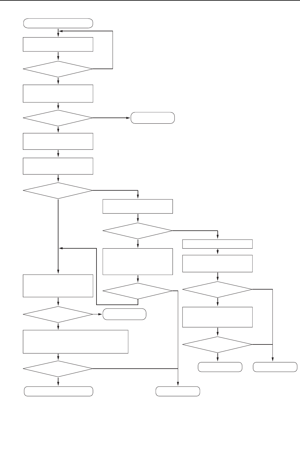
[ IX Troubleshooting ]
- 325 -
HWE09080 GB
(2) Solenoid valve (SVA, SVB, SVC)
Stop the operation of the applied
BC remote controller system.
Faulty judgment of solenoid valve
Faulty judgment of solenoid valve
Solenoid valve failure
Replace the control board.
Replace the solenoid valve coil.
Repair the fault.
Replace the control board.
Stop the operation
Note 1
Check whether the wire to the
solenoid valve is not connected
wrongly, or the connector is not loose.
No fault
Check the operation sound of the solenoid
valve to be magnetized at the time of
turning on the remote controller.
Makes a tick sound.
Check the relay output with the
self-diagnosis LED, and check
whether the operation corresponds
with the operation mode.
Corresponds
Measure the temperature at the upstream
and downstream pipes of the solenoid valve.
When the solenoid valve is ON : There is no temperature difference.
When the solenoid valve is OFF : There is a temperature difference.
OK
Remove the solenoid valve coil, and
check that there is a suction force.
There is a suction force.
Note 2
Note 2
Note 2
Measure the temperature at the upstream
and downstream pipes of the solenoid
valve, and compare them.
There is no temperature difference. : OK
There is a temperature difference. : NO
OK
Run the cooling or heating operation
of the refrigerant system of the
solenoid valve in trouble.
NO
NO
NO
Stop the unit with the remote controller.
Remove the solenoid valve connector, and
check that the electricity runs through the
solenoid valve coil.
The electricity runs.
Output 230V
NO
NO NO
NO
YES
YES
YES
YES
YES
YES
YES
YES
YES
Turn on the remote controller with the
connector of the solenoid valve in trouble
disconnected, and check that the control
board outputs 230V.
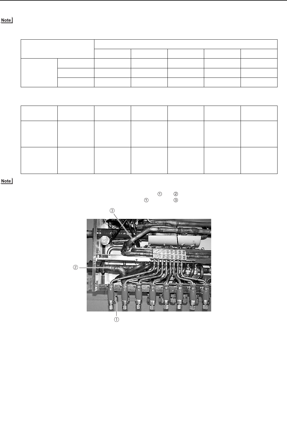
[ IX Troubleshooting ]
- 326 -
HWE09080 GB
Check whether the BC board output signal corresponds with the solenoid valve operation correspond.
1) SVA, SVB, SVC
SVA, SVB, and SVC turn on or off according to the indoor unit operation mode.
SVM1, SVM1b, SVM2, SVM2b
SVM1, SVM1b, SVM2, and SVM2b turn on or off according to the indoor unit operation mode.
2) SVA, SVB, SVC
Measure the temperature at the upstream and downstream pipes and of SVA.
Measure the temperature at the upstream and downstream pipes and of SVB.
Mode
Cooling Heating Stopped Defrost Fan
Port
SVA ON OFF OFF OFF OFF
SVB OFF ON OFF OFF OFF
SVC ON OFF OFF OFF ON
Operation
mode Cooling only Cooling main Heating only Heating main Defrost Stopped
SVM1,SVM1b ON
Pressure dif-
ferential con-
trol OFF or
ON
OFF OFF ON OFF
SVM2,
SVM2b OFF OFF
Pressure dif-
ferential con-
trol OFF or
ON
Pressure dif-
ferential con-
trol OFF or
ON
OFF OFF
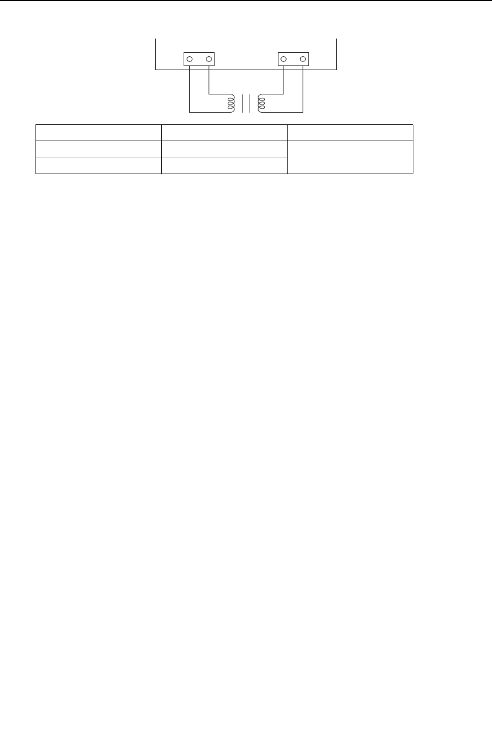
[ IX Troubleshooting ]
- 327 -
HWE09080 GB
4. BC controller transformer
* Before measuring the resistance, pull out the connector.
Normal Abnormal
CNTR(1)-(3) about 58 ohm.
Open-phase or shorting
CN03(1)-(3) about 1.6 ohm.
CNTR CN03
BC controller control board
Red White Red Red
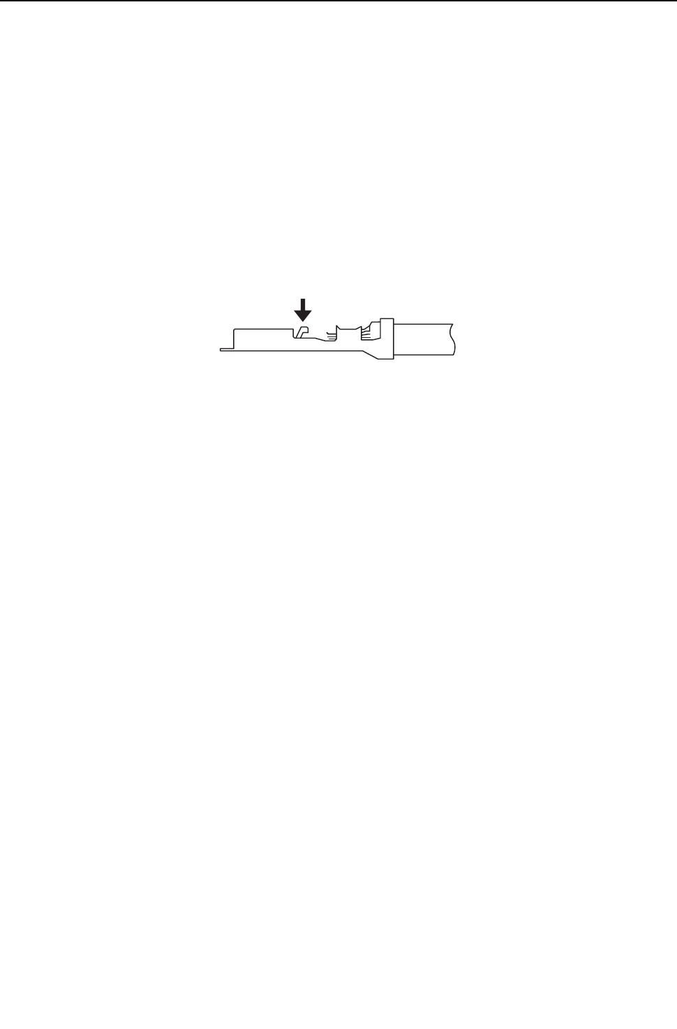
[ IX Troubleshooting ]
- 328 -
HWE09080 GB
-6- Inverter (THMU-A)
Replace only the compressor if only the compressor is found to be defective. (Overcurrent will flow through the inverter if the
compressor is damaged, however, the power supply is automatically cut when overcurrent is detected, protecting the inverter
from damage.)
Replace the defective components if the inverter is found to be defective.
If both the compressor and the inverter are found to be defective, replace the defective component(s) of both devices.
(1) Inverter-related problems: Troubleshooting and remedies
1) The INV board has a large-capacity electrolytic capacitor, in which residual voltage remains even after the main power is
turned off, posing a risk of electric shock. Before inspecting the inverter-related items, turn off the main power, wait for 5 to 10
minutes, and confirm that the voltage at both ends of the electrolytic capacitor has dropped to a sufficiently low level.
2) The IPM on the inverter becomes damaged if there are loose screws are connectors. If a problem occurs after replacing some
of the parts, mixed up wiring is often the cause of the problem. Check for proper connection of the wiring, screws, connectors,
and Faston terminals.
3) To avoid damage to the circuit board, do not connect or disconnect the inverter-related connectors with the main power turned
on.
4) Faston terminals have a locking function. Make sure the terminals are securely locked in place after insertion.
5) When the IPM, diode stack, or IGBT is replaced, apply a thin layer of heat radiation grease that is supplied evenly to these
parts. Wipe off any grease that may get on the wiring terminal to avoid terminal contact failure.
6) Faulty wiring to the compressor damages the compressor. Connect the wiring in the correct phase sequence.
Press the tab on the terminals to remove them.
[THMU-A]
[ IX Troubleshooting ]
- 329 -
HWE09080 GB
Error display/failure condition Measure/inspection item
[1] Inverter related errors
4250, 4220, 4230, 4240,4260, 5301, 0403
Check the details of the inverter error in the error log in X LED Monitor
Display on the Heat source Unit Board.
Take appropriate measures to the error code and the error details in ac-
cordance with IX. [2] Responding to Error Display on the Remote Con-
troller.
[2] Main power breaker trip <1> Check the breaker capacity.
<2> Check whether the electrical system is short-circuited or ground-
faulted.
<3> If items cause is not <1>or <2> are not the causes of the problem,
see (3)-[1].
[3] Main power earth leakage breaker trip <1> Check the earth leakage breaker capacity and the sensitivity cur-
rent.
<2> Meg failure for electrical system other than the inverter
<3> If the cause is not <1>or <2>, see (3)-[1]
[4] Only the compressor does not operate. Check the inverter frequency on the LED monitor and proceed to (2) -
[4] if the compressor is in operation.
[5] The compressor vibrates violently at all times or makes an abnor-
mal sound.
See (2)-[4].
[6] Noise is picked up by the peripheral device <1> Check that power supply wiring of the peripheral device does not
run close to the power supply wiring of the heat source unit.
<2> Check that the inverter output wiring is not in close contact with the
power supply wiring and the transmission lines.
<3> Check that the shielded wire is used as the transmission line when
it is required, and check that the grounding work is performed prop-
erly on the shielded wire.
<4> Meg failure for electrical system other than the inverter
<5> Attach a ferrite core to the inverter output wiring. (Contact the fac-
tory for details of the service part settings.)
<6> Provide separate power supply to the air conditioner and other
electric appliances.
<7> If the error occurred suddenly, a ground fault of the inverter output
can be considered. See (2)-[4].
*Contact the factory for cases other than those listed above.
[7] Sudden malfunction (as a result of external noise.) <1> Check that the grounding work is performed properly.
<2>Check that the shielded wire is used as the transmission line when
it is required, and check that the grounding work is performed prop-
erly on the shielded wire.
<3>Check that neither the transmission line nor the external connec-
tion wiring does not run close to another power supply system or
does not run through the same conduit pipe.
* Contact the factory for cases other than those listed above.
[THMU-A]

[ IX Troubleshooting ]
- 330 -
HWE09080 GB
(2) Inverter output related troubles
Items to be checked Phenomena Remedy
[1]
Check the INV
board error
detection cir-
cuit.
(1) Disconnect the invert-
er output wire from
the terminals of the
INV board (SC-U,
SC-V, SC-W).
1) IPM/overcurrent breaker trip
Error code: 4250
Detail code: No. 101, 104, 105, 106,
and 107
Replace the INV board.
(2) Put the heat source
unit into operation.
2) Logic error
Error code: 4220
Detail code: No. 111
Replace the INV board.
3) ACCT sensor circuit failure
Error code: 5301
Detail code: No.117
Replace the INV board.
4) IPM open
Error code: 5301
Detail code: No.119
Normal
[2]
Check for
compressor
ground fault or
coil error.
Disconnect the compres-
sor wiring, and check the
compressor Meg, and coil
resistance.
1) Compressor Meg failure
Error if less than 1 Mohm.
When no liquid refrigerant in the
compressor
Check that no liquid refrigerant is
present in the compressor, and re-
place the compressor.
2) Compressor coil resistance failure
Coil resistance value of 0.3 ohm
(20°C [68°F])
Replace the compressor.
[3]
Check wheth-
er the inverter
is damaged.
(No load)
(1) Disconnect the invert-
er output wire from
the terminals of the
INV board (SC-U,
SC-V, SC-W).
1) Inverter-related problems are de-
tected.
Connect the short-circuit connec-
tor to CN6, and go to section [1].
(2) Disconnect the short-
circuit connector from
CN6 on the INV
board.
2) Inverter voltage is not output. Replace the INV board.
(3) Put the heat source
unit into operation.
Check the inverter
output voltage after
the inverter output
frequency has stabi-
lized.
3) There is an voltage imbalance be-
tween the wires.
Greater than 5% imbalance or 5V
Replace the INV board.
4) There is no voltage imbalance be-
tween the wires.
Normal
*Reconnect the short-circuit con-
nector to CN6 after checking the
voltage.
[4]
Check wheth-
er the inverter
is damaged.
(During com-
pressor oper-
ation)
Put the heat source unit
into operation.
Check the inverter output
voltage after the inverter
output frequency has sta-
bilized.
1) There is an voltage imbalance be-
tween the wires.
Greater than 5% imbalance or 5V
If the problem persists, replace the
INV board.
If the problem persists after replac-
ing the above parts, go to section
[2].
[THMU-A]
[ IX Troubleshooting ]
- 331 -
HWE09080 GB
(3) Trouble treatment when the main power breaker is tripped.
(4) Trouble treatment when the main power earth leakage breaker is tripped
The insulation resistance could go down to close to 1Mohm after installation or when the power is kept off for an extended
period of time because of the accumulation of refrigerant in the compressor. If the earth leakage breaker is triggered, please
use the following procedure to take care of this.
Disconnect the wires from the compressor's terminal block.
If the resistance is less than 1 Mohm, switch on the power for the heat source unit with the wires still disconnected.
Leave the power on for at least 12 hours.
Check that the resistance has recovered to 1 Mohm or greater.
Earth leakage current measurement method
For easy on-site measurement of the earth leakage current, enable the filter with a measurement instrument that has filter
functions as below, clamp all the power supply wires, and measure.
Recommended measurement instrument: CLAMP ON LEAK HiTESTER 3283 made by HIOKI E.E. CORPORATION
When measuring one device alone, measure near the device's power supply terminal block.
Items to be checked Phenomena Remedy
[1] Perform Meg check between the
terminals on the power terminal
block TB1.
Zero to several ohm, or Meg failure Check each part in the main inverter
circuit.
*Refer to "Simple checking procedures
for individual components of main in-
verter circuit".
IGBT module
IPM
Rush current protection resistor
Electromagnetic relay
DC reactor
[2] Turn on the power again and
check again.
1) Main power breaker trip
2) No remote control display
[3] Turn on the heat source unit and
check that it operates normally.
1) Operates normally without tripping
the main breaker.
a) The wiring may have been short-
circuited. Search for the wire that
short-circuited, and repair it.
b) If item a) above is not the cause of
the problem, the compressor may
have a problem.
2) Main power breaker trip A compressor ground fault can be con-
sidered. Go to (2)-[2].
Items to be checked Phenomena Remedy
[1] Check the earth leakage breaker
capacity and the sensitivity cur-
rent.
Use of a non-specified earth
leakage breaker
Replace with a regulation earth leakage
breaker.
[2] Check the resistance at the power
supply terminal block with a meg-
ger.
Failure resistance value Check each part and wiring.
*Refer to (5) "Simple checking procedures
for individual components of main inverter
circuit".
IGBT module
Rush current protection resistor
Electromagnetic relay
DC reactor
[3] Disconnect the compressor wir-
ings and check the resistance of
the compressor with a megger.
Failure compressor if the insu-
lating resistance value is not in
specified range.
Failure when the insulating re-
sistance value is 1 Mohm or
less.
Check that there is no liquid refrigerant in
the compressor. If there is none, replace
the compressor.
[THMU-A]
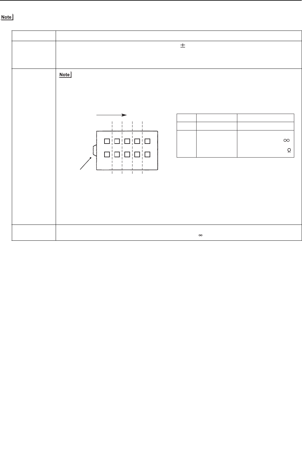
[ IX Troubleshooting ]
- 332 -
HWE09080 GB
(5) Simple checking procedure for individual components of main inverter circuit
Before checking, turn the power off and remove the parts to be checked from the control box.
Part name Judgment method
Rush current
protection resis-
tor
R1(R2)
Measure the resistance between terminals: 22 ohm 10%
Electromagnetic
relay
72C This electromagnetic relay is rated at 200VAC and is driven by a coil. The resistance between the
coils in row A cannot be measured with a tester.Check only for shorting.
DC reactor DCL Measure the resistance between terminals: 1ohm or lower (almost 0 ohm)
Measure the resistance between terminals and the chassis:
Check point
Row A
Not to be short-circuited
Row B to Row E
Installation direction
Test button
Row
A
Row
B
Row
C
Row
D
Row
E
A2 44 34 24 14
43 33 23 13
A1
Coil
Contact
Checking criteria
With the test button
turned off :
With the test button
turned on : 0
[THMU-A]
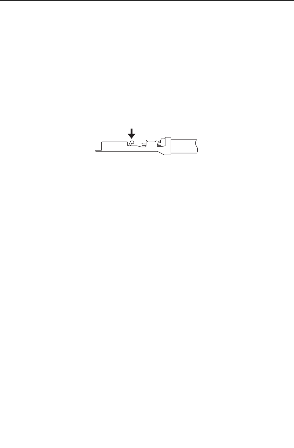
[ IX Troubleshooting ]
- 333 -
HWE09080 GB
-6- Inverter (YHMU-A)
Replace only the compressor if only the compressor is found to be defective.
Replace the defective components if the inverter is found to be defective.
If both the compressor and the inverter are found to be defective, replace the defective component(s) of both devices.
(1) Inverter-related problems: Troubleshooting and remedies
1) The INV board has a large-capacity electrolytic capacitor, in which residual voltage remains even after the main power is
turned off, posing a risk of electric shock. Turn off the unit, leave it turned off for at least 10 minutes, and check that the voltage
across FT-P and FT-N terminals on the INV board or the terminals at both ends of the electrolytic capacitor is 20V or below
before checking inside the control box.
(It takes about 10 minutes to discharge electricity after the power supply is turn off.)
2) The IPM on the inverter becomes damaged if there are loose screws are connectors. If a problem occurs after replacing some
of the parts, mixed up wiring is often the cause of the problem. Check for proper connection of the wiring, screws, connectors,
and Faston terminals.
3) To avoid damage to the circuit board, do not connect or disconnect the inverter-related connectors with the main power turned
on.
4) Faston terminals have a locking function. Make sure the terminals are securely locked in place after insertion.
5) When the IPM or IGBT is replaced, apply a thin layer of heat radiation grease that is supplied evenly to these parts. Wipe off
any grease that may get on the wiring terminal to avoid terminal contact failure.
6) Faulty wiring to the compressor damages the compressor. Connect the wiring in the correct phase sequence.
Press the tab on the terminals to remove them.
[YHMU-A]
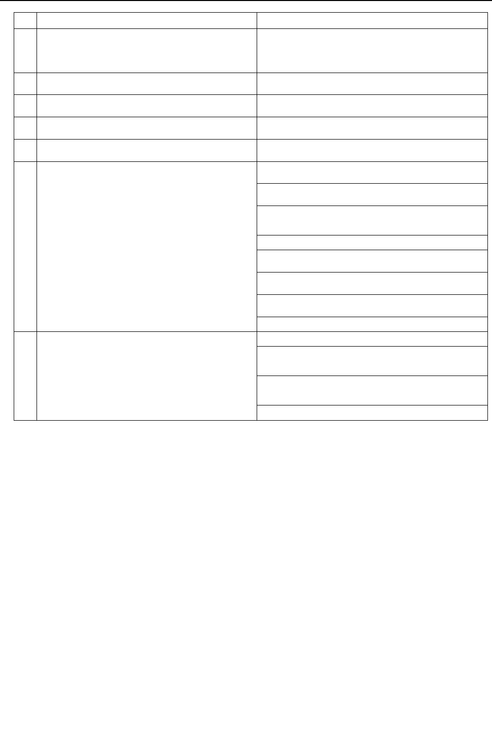
[ IX Troubleshooting ]
- 334 -
HWE09080 GB
Error display/failure condition Measure/inspection item
[1] Inverter related errors
4250, 4220, 4230, 4240,4260, 5301, 0403
Check the details of the inverter error in the error log in X LED Monitor
Display on the Heat source Unit Board.
Take appropriate measures to the error code and the error details in ac-
cordance with IX. [2] Responding to Error Display on the Remote Con-
troller.
[2] Main power breaker trip Refer to "(3) Trouble treatment when the main power breaker is
tripped".
[3] Main power earth leakage breaker trip Refer to "(4) Trouble treatment when the main power earth leakage
breaker is tripped".
[4] Only the compressor does not operate. Check the inverter frequency on the LED monitor and proceed to (2) -
[4] if the compressor is in operation.
[5] The compressor vibrates violently at all times or makes an abnor-
mal sound.
See (2)-[4].
[6] Noise is picked up by the peripheral device <1> Check that power supply wiring of the peripheral device does not
run close to the power supply wiring of the heat source unit.
<2> Check if the inverter output wiring is not running parallel to the
power supply wiring and the transmission lines.
<3> Check that the shielded wire is used as the transmission line when
it is required, and check that the grounding work is performed prop-
erly on the shielded wire.
<4> Meg failure for electrical system other than the inverter
<5> Attach a ferrite core to the inverter output wiring. (Contact the fac-
tory for details of the service part settings.)
<6> Provide separate power supply to the air conditioner and other
electric appliances.
<7> If the error occurred suddenly, a ground fault of the inverter output
can be considered. See (2)-[4].
*Contact the factory for cases other than those listed above.
[7] Sudden malfunction (as a result of external noise.) <1> Check that the grounding work is performed properly.
<2>Check that the shielded wire is used as the transmission line when
it is required, and check that the grounding work is performed prop-
erly on the shielded wire.
<3>Check that neither the transmission line nor the external connec-
tion wiring does not run close to another power supply system or
does not run through the same conduit pipe.
* Contact the factory for cases other than those listed above.
[YHMU-A]

[ IX Troubleshooting ]
- 335 -
HWE09080 GB
(2) Inverter output related troubles
Items to be checked Phenomena Remedy
[1]
Check the
INV board er-
ror detection
circuit.
(1) Disconnect the invert-
er output wire from
the terminals of the
INV board (SC-U,
SC-V, SC-W).
1) Overcurrent error
Error code: 4250
Detail code: No. 101, 104, 105,
106, and 107
Replace the INV board.
(2) Put the heat source
unit into operation.
2) Logic error
Error code: 4220
Detail code: No. 111
Replace the INV board.
3) ACCT sensor circuit failure
Error code: 5301
Detail code: No.117
Replace the INV board.
4) IPM open
Error code: 5301
Detail code: No.119
Normal
[2]
Check for
compressor
ground fault
or coil error.
Disconnect the compressor
wiring, and check the com-
pressor Meg, and coil resis-
tance.
1) Compressor Meg failure
Error if less than 1 Mohm.
Check that there is no liquid re-
frigerant in the compressor.
If there is none, replace the com-
pressor.
2) Compressor coil resistance failure
Coil resistance value of 1 ohm
(20°C [68°F])
Replace the compressor.
[3]
Check wheth-
er the inverter
is damaged.
(No load)
(1) Disconnect the invert-
er output wire from
the terminals of the
INV board (SC-U,
SC-V, SC-W).
1) Inverter-related problems are de-
tected.
Connect the short-circuit connec-
tor to CN6, and go to section [1].
(2) Disconnect the short-
circuit connector from
CN6 on the INV
board.
2) Inverter voltage is not output at the
terminals (SC-U, SC-V, and SC-W)
Replace the INV board.
(3) Put the heat source
unit into operation.
Check the inverter
output voltage after
the inverter output
frequency has stabi-
lized.
3) There is an voltage imbalance be-
tween the wires.
Greater than 5% imbalance or 5V
Replace the INV board.
4) There is no voltage imbalance be-
tween the wires.
Normal
*Reconnect the short-circuit con-
nector to CN6 after checking the
voltage.
[4]
Check wheth-
er the inverter
is damaged.
(During com-
pressor oper-
ation)
Put the heat source unit into
operation.
Check the inverter output
voltage after the inverter
output frequency has stabi-
lized.
1) There is an voltage imbalance be-
tween the wires.
Greater than 5% imbalance or 5V
Replace the INV board.
[YHMU-A]
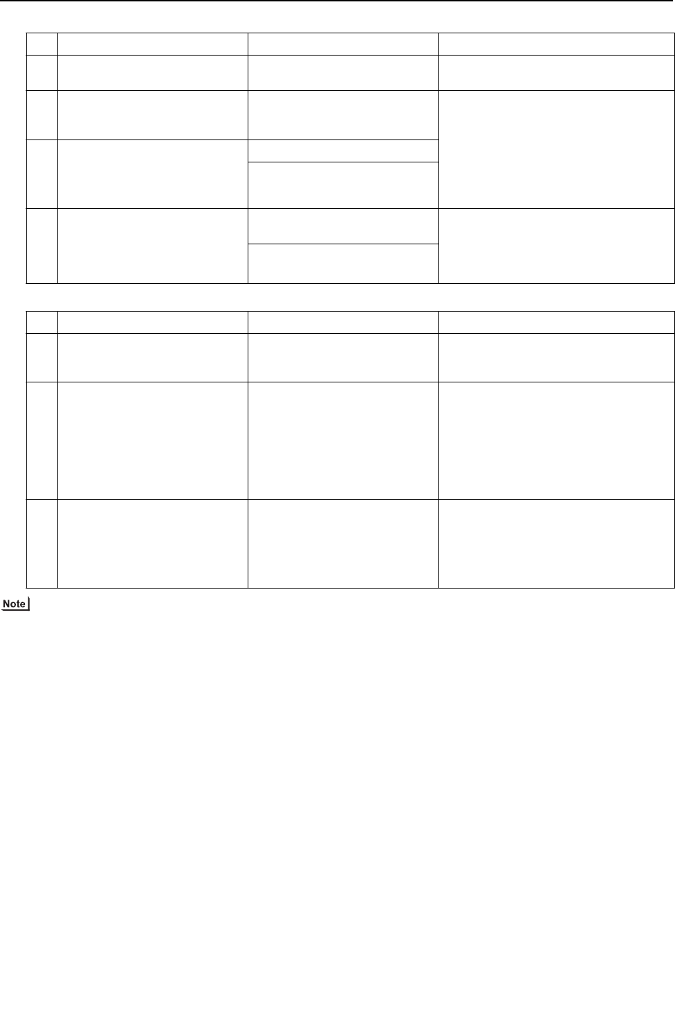
[ IX Troubleshooting ]
- 336 -
HWE09080 GB
(3) Trouble treatment when the main power breaker is tripped
(4) Trouble treatment when the main power earth leakage breaker is tripped
The insulation resistance could go down to close to 1Mohm after installation or when the power is kept off for an extended
period of time because of the accumulation of refrigerant in the compressor. If the earth leakage breaker is triggered, please
use the following procedure to take care of this.
Disconnect the wires from the compressor's terminal block.
If the resistance is less than 1 Mohm, switch on the power for the heat source unit with the wires still disconnected.
Leave the power on for at least 12 hours.
Check that the resistance has recovered to 1 Mohm or greater.
Earth leakage current measurement method
For easy on-site measurement of the earth leakage current, enable the filter with a measurement instrument that has filter
functions as below, clamp all the power supply wires, and measure.
Recommended measurement instrument: CLAMP ON LEAK HiTESTER 3283 made by HIOKI E.E. CORPORATION
When measuring one device alone, measure near the device's power supply terminal block.
Items to be checked Phenomena Remedy
[1] Check the breaker capacity. Use of a non-specified break-
er
Replace it with a specified breaker.
[2] Perform Meg check between the
terminals on the power terminal
block TB1.
Zero to several ohm, or Meg
failure
Check each part and wiring.
*Refer to (5) "Simple checking procedures
for individual components of main inverter
circuit".
IGBT module
Rush current protection resistor
Electromagnetic relay
DC reactor
[3] Turn on the power again and
check again.
1) Main power breaker trip
2) No remote control display
[4] Turn on the heat source unit and
check that it operates normally.
1) Operates normally without
tripping the main breaker.
a) The wiring may have been short-circuit-
ed. Search for the wire that short-circuit-
ed, and repair it.
b) If item a) above is not the cause of the
problem, refer to (2)-[1]-[6].
2) Main power breaker trip
Items to be checked Phenomena Remedy
[1] Check the earth leakage breaker
capacity and the sensitivity cur-
rent.
Use of a non-specified earth
leakage breaker
Replace with a regulation earth leakage
breaker.
[2] Check the resistance at the power
supply terminal block with a meg-
ger.
Failure resistance value Check each part and wiring.
*Refer to (5) "Simple checking procedures
for individual components of main inverter
circuit".
IGBT module
Rush current protection resistor
Electromagnetic relay
DC reactor
[3] Disconnect the compressor wir-
ings and check the resistance of
the compressor with a megger.
Failure compressor if the insu-
lating resistance value is not in
specified range.
Failure when the insulating re-
sistance value is 1 Mohm or
less.
Check that there is no liquid refrigerant in
the compressor. If there is none, replace
the compressor.
[YHMU-A]
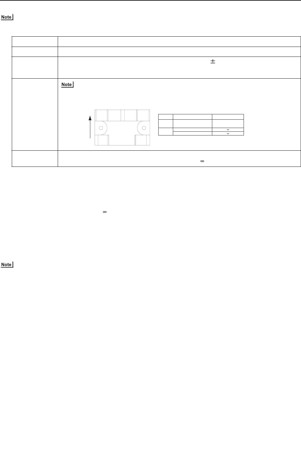
[ IX Troubleshooting ]
- 337 -
HWE09080 GB
(5) Simple checking procedure for individual components of main inverter circuit
Before inspecting the inside of the control box, turn off the power, keep the unit off for at least 10 minutes, and confirm that
the voltage between FT-P and FT-N on INV Board has dropped to DC20V or less.
(6) Troubleshooting for IGBT Module
Measure the resistances between each pair of terminals on the IGBT with a tester, and use the results for troubleshooting.
The terminals on the INV board are used for the measurement.
1) Notes on measurement
Check the polarity before measuring. (On the tester, black normally indicates plus.)
Check that the resistance is not open ( ohm) or not shorted (to 0 ohm).
The values are for reference, and the margin of errors is allowed.
The result that is more than double or half of the result that is measured at the same measurement point is not allowed.
Disconnect all the wiring connected the INV board, and make the measurement.
2) Tester restriction
Use the tester whose internal electrical power source is 1.5V or greater
Use the dry-battery-powered tester.
(The accurate diode-specific resistance cannot be measured with the button-battery-powered card tester, as the applied volt-
age is low.)
Use a low-range tester if possible. A more accurate resistance can be measured.
Part name Judgment method
IGBT module See "Troubleshooting for IGBT Module ". ( 9 [4] - 6 - (6) )
Rush current pro-
tection resistor
R1, R5
Measure the resistance between terminals R1 and R5: 22 ohm 10%
Electromagnetic
relay
72C This electromagnetic relay is rated at DC12V and is driven by a coil.
Check the resistance between terminals
DC reactor DCL Measure the resistance between terminals: 1ohm or lower (almost 0 ohm)
Measure the resistance between terminals and the chassis:
1
65
234
Upper
Installation
direction
Check point Checking criteria( )
W
Between Terminals 5 and 6
Between Terminals 1 and 2
Between Terminals 3 and 4
Not to be short-circuited
(Center value 75 ohm)
Coil
Contact
[YHMU-A]
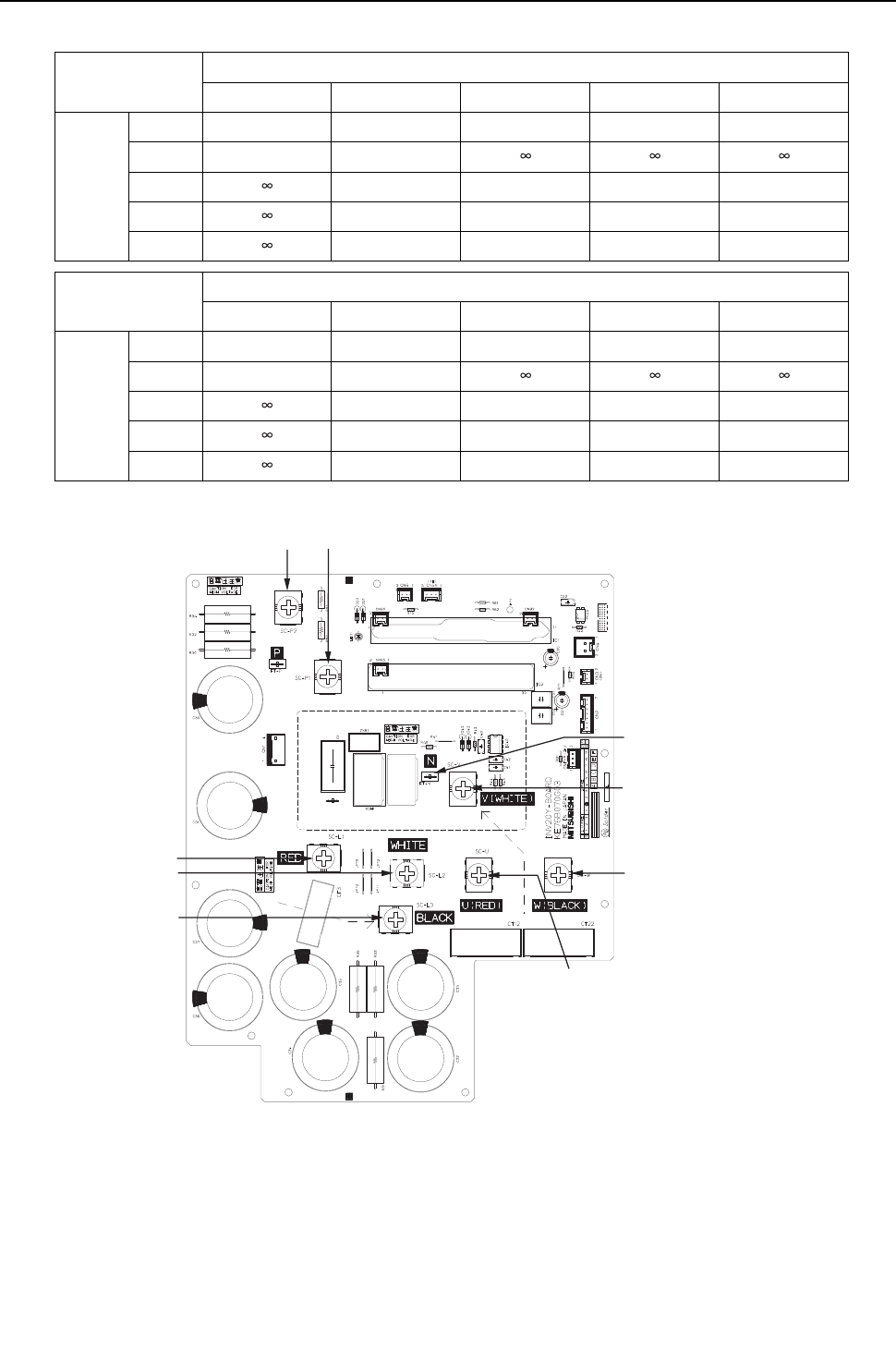
[ IX Troubleshooting ]
- 338 -
HWE09080 GB
INV board external diagram
Judgment value (reference)
Black
SC-P1 FT-N SC-L1 SC-L2 SC-L3
Red
SC-P1 - - 5 - 200 ohm 5 - 200 ohm 5 - 200 ohm
FT-N - -
SC-L1 5 - 200 ohm - - -
SC-L2 5 - 200 ohm - - -
SC-L3 5 - 200 ohm - - -
Black
SC-P2 FT-N SC-U SC-V SC-W
Red
SC-P2 - - 5 - 200 ohm 5 - 200 ohm 5 - 200 ohm
FT-N - -
SC-U 5 - 200 ohm - - -
SC-V 5 - 200 ohm - - -
SC-W 5 - 200 ohm - - -
SC-U
SC-W
SC-V
FT-N
SC-P1SC-P2
SC-L1
SC-L2
SC-L3
[YHMU-A]
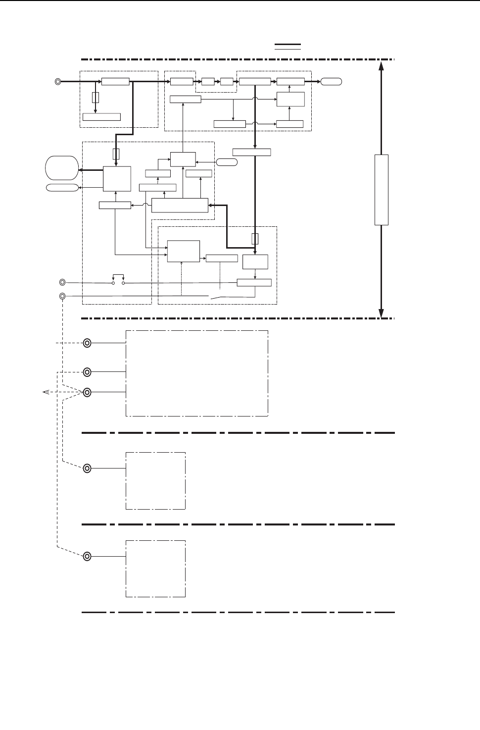
[ IX Troubleshooting ]
- 339 -
HWE09080 GB
-7- Control Circuit (THMU-A)
(1) Control power source function block
Heat source unit
Power source system (AC 208 / 230 V)
Control system (DC 5 ~ 30 V)
* MA remote controllers and M-NET remote controllers cannot be used together.
(Both the M-NET and MA remote controller can be connected to a system with a system controller.)
A, B
A, B
M-NET
transmission line
(Non-polar 2 wire)
AC 208 / 230 V
AC Power source
To next unit
(Indoor unit)
MA remote controller wiring
(Non-polar 2 wire)
DC 17 ~ 30 V
DC 9 ~ 12 V
M-NET remote
controller
MA remote
controller
Indoor unit
TB2
TB15
Terminal block for
power source
TB5
Terminal block
for MA remote
controller
Terminal block
for transmission
line connection
DC 17 ~ 30 V
AC 208 / 230 V
Terminal block for
power source
TB1
Noise filter
Noise filter
Fuse
Fuse
Fuse
LEV
Surge protection
INV board
Control board
63H1
72C DCL
DC / DC converter
Detection circuit for
the power supply to
the transmission line
M-NET board
DC / DC
converter
Microcomputer
Microcomputer
5 V Power supply
18 V Power supply
12V Power supply
30 V Power supply
Relay drive circuit
Relay
5 V Power supply
17V Power supply
Smoothing capacitor
Inverter
Inverter drive
circuit
Inverter reset
circuit
Rectifier
Compressor
Smoothing capacitor
Relay, LEV
Drive circuit
72C
Solenoid valve
4-way valve
CH11
CN40
Terminal block for
transmission line
for centralized control
(DC 24 ~ 30 V)
TB7
Indoor/heat source
transmission block
(DC 24 ~ 30 V)
TB3
[THMU-A]
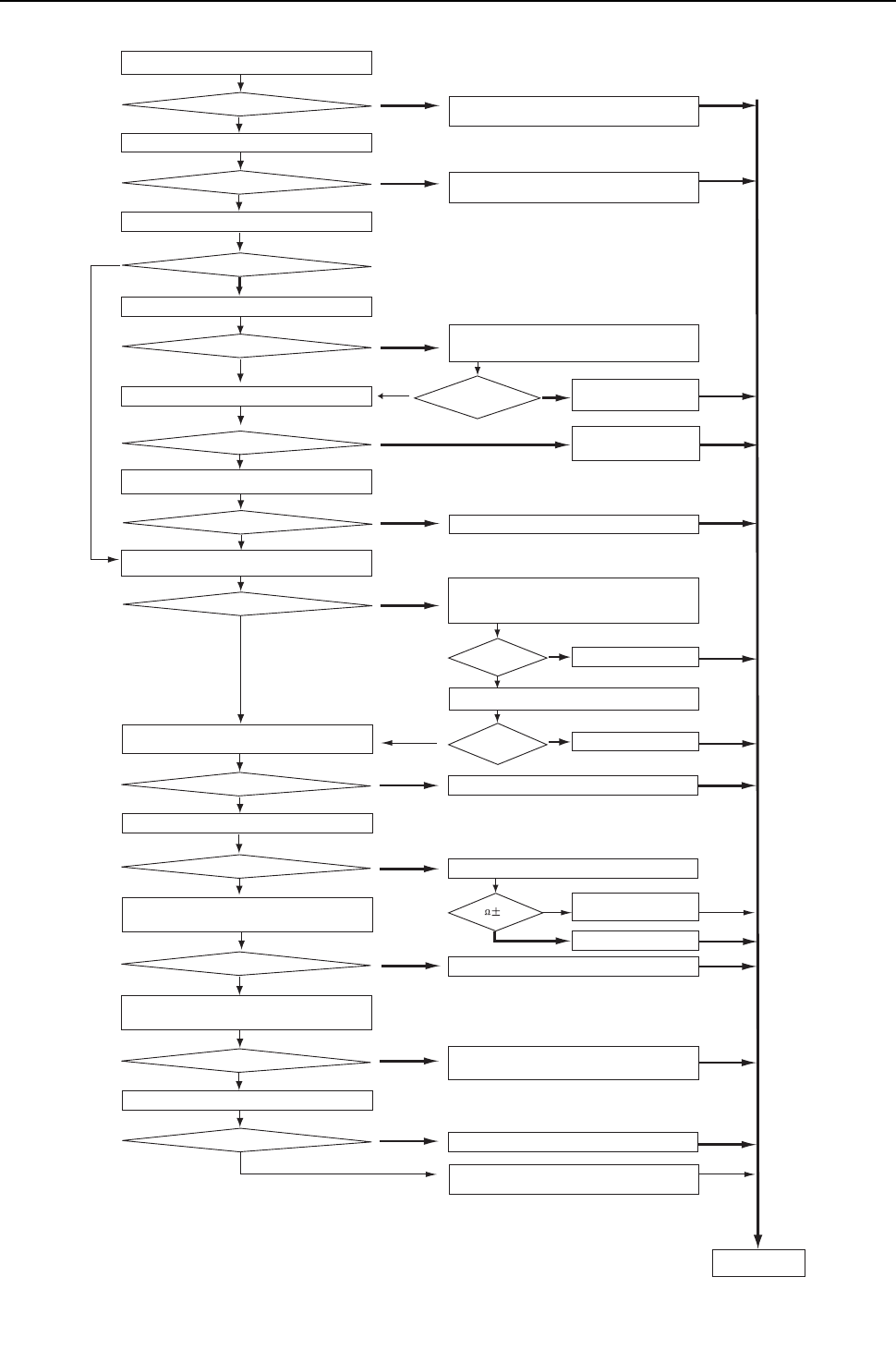
[ IX Troubleshooting ]
- 340 -
HWE09080 GB
(2) Troubleshooting transmission power circuit of heat source unit
Check the voltage between No.1 and No.2 pins of the
CNS2 on the control board.
Check the wiring between the control board and power
supply board for the transmission line (CN102 and CNIT),
and check for proper connection of connectors.
Check the wiring between the control board and power
supply board for the transmission line (CN102 and CNIT),
and check for proper connection of connectors.
Is there a wiring
error or a connector
disconnection?
Check the voltage between No.5 and No.2 pins
of the CNIT on the control board.
Is the voltage
measurement between
4.5 and 5.2 VDC?
Is there a connector
disconnection?
Fix the connector disconnection.
Replace the M-NET board
Replace the M-NET board
Replace the inrush current
limiting resistor.
Replace the INV board.
Replace the INV board.
Check the wiring between the noise filter and the
INV board as well as screw tightness, and fix any
problems found.
Replace the noise filter.
Check and fix any power supply wiring and main power
supply problems found.
Check the inrush current resistance (R1).
Fix the wiring and connector
disconnection.
Check for shorted transmission
line for centralized control.
Replace the control board.
Check the voltage between No.1 and No.2 pins of the
CN102 on the power supply board for the transmission line.
Check the voltage between No.1 and No.3 pins of
the CNDC on the INV board.
Check the voltage between SC-P1 and TB-N on the INV board.
Check the voltages among SC-R, SC-S, and
SC-T on the INV board.
Check the voltages among TB21, TB22, and
TB23 on the noise filter.
Check the voltage at the power supply terminal block TB1.
DC24
~
30V
DC24
~
30V
DC24
~
30V
DC265
~
357V
DC265
~
357V
AC188
~
253V
AC188
~
253V
AC188
~
253V
DC24
~
30V
Turn on the
power again.
YES
YES
YES
YES
YES
YES
YES
YES
YES
YES
YES
YES
YES
YES
YES
YES
NO
NO
NO
NO
NO
NO
NO
NO
NO
NO
NO
NO
NO
NO
NO
NO
22 10%
Check the voltage at the indoor/heat source
transmission terminal block (TB3) of heat source unit.
DC 24 ~ 30 V
DC 24 ~ 30 V
Check the voltage at TB3 after removing transmission line from TB3.
Check whether the male connector is connected to
the female power supply connector (CN40).
Connected
Check voltage of terminal block for centralized control (TB7).
Check voltage of TB7 by removing transmission line from TB7.
Check if the indoor/heat source transmission line
is not short-circuited, and repair the problem.
Check whether the transmission line is disconnected,
check for contact failure, and repair the problem.
[THMU-A]
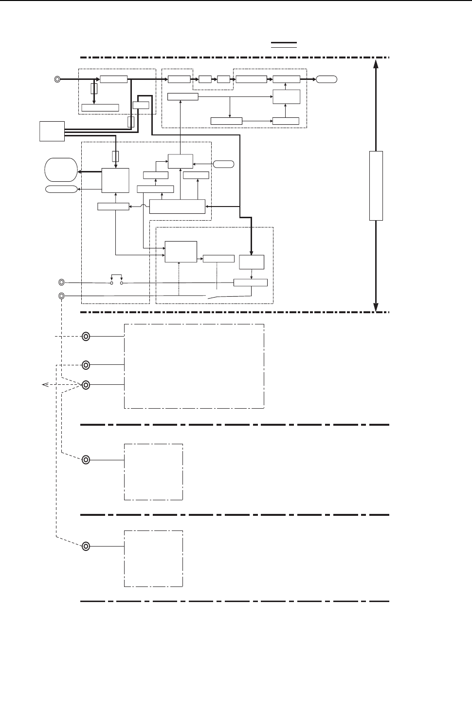
[ IX Troubleshooting ]
- 341 -
HWE09080 GB
-7- Control Circuit (YHMU-A)
(1) Control power source function block
Power source system (AC 230 / 460 V)
Control system (DC 5 ~ 30 V)
* MA remote controllers and M-NET remote controllers cannot be used together.
(Both the M-NET and MA remote controller can be connected to a system with a system controller.)
A, B
A, B
M-NET
transmission line
(Non-polar 2 wire)
AC 220 / 240 V
AC Power source
To next unit
(Indoor unit)
MA remote controller wiring
(Non-polar 2 wire)
DC 17 ~ 30 V
DC 9 ~ 12 V
TB2
TB15
Terminal block for
power source
TB5
Terminal block
for MA remote
controller
Terminal block
for transmission
line connection
DC 17 ~ 30 V
AC 460V
Terminal block for
power source
TB1
Noise filter
Noise filter
Fuse
Fuse
Fuse
72C, LEV
Surge protection
INV board
Control board
63H1
72C DCL
DC / DC converter
Detection circuit for
the power supply to
the transmission line
M-NET board
DC / DC
converter
Microcomputer
Microcomputer
5 V Power supply
18 V Power supply
12V Power supply
AC460V
AC230V AC230V
30 V Power supply
Relay drive circuit
Relay
5 V Power supply
17V Power supply
Smoothing capacitor
Inverter
Inverter drive
circuit
Inverter reset
circuit
Rectifier
Compressor
Relay, LEV
Drive circuit
Solenoid valve
4-way valve
CH11
CN40
Terminal block for
transmission line
for centralized control
(DC 24 ~ 30 V)
TB7
Indoor/heat source
transmission block
(DC 24 ~ 30 V)
TB3
Rectifier
Transformer
M-NET remote
controller
MA remote
controller
Indoor unit
Heat source unit
[YHMU-A]
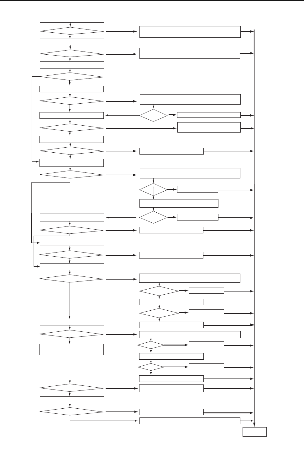
[ IX Troubleshooting ]
- 342 -
HWE09080 GB
(2) Troubleshooting transmission power circuit of heat source unit
YES
YES
YES
YES
YES
YES
NO
NO
NO
NO
NO
NO
DC270
~
356V
AC41
4
~
506V
Fuse
F4 on the noise filter board is blown.
AC414
~
506V
YES
YES
YES
YES
YES
NO
NO
NO
NO
NO
NO
YES
NO
YES
YES
NO
NO
NO
YES
YES
YES
NO
NO
NO
YES
NO
YES
Check the voltage between L2 and L3 at the power supply
terminal block TB1.
Check the voltages among TB22 and TB23 on the
noise filter
Fuse
F5 is blown.
Fuse F5 is blown.
Fuse F5 is blown.
Check
fuse
F5.
Pull out CN4 and CN5 on the noise filter, replace fuse F5, and turn on the power.
YES
Check the voltage at the indoor/heat source
transmission terminal block (TB3) of heat source unit.
DC 24 ~ 30 V
Check the voltage at TB3 after removing transmission line from TB3.
DC 24 ~ 30 V
DC 24 ~ 30 V
DC 24 ~ 30 V
DC 24 ~ 30 V
DC 24 ~ 30 V
Check whether the male connector is connected to
the female power supply connector (CN40).
Connected
Check voltage of terminal block for centralized control (TB7).
Check voltage of TB7 by removing transmission line from TB7.
Check the voltage between No.1 and No.2 pins of the
CNS2 on the control board.
Check the voltage between No.1 and No.3 pins of
the noise filter CN4.
DC270
~
356V
Check the voltage between No.1 and No.3 pins of
the noise filter CN5.
Check the noise filter fuse F4 .
Turn on the
power again.
Check and fix any power supply wiring and main power supply problems found.
Replace the noise filter.
Replace the noise filter.
Replace the M-NET board
Connect the noise filter CN4, and then turn the power on.
Replace the control board.
Replace the noise filter.
Replace the noise filter.
Replace the control board.
Fuse F4 on the
noise filter board is blown.
Fuse F4 on the
noise filter board is blown.
Disconnect the noise filters CN4 and CN5, and then replace fuse F4 on the noise filter
board, then turn the power on.
Connect the noise filter CN4, and then turn the power on.
Replace the M-NET board
Replace the M-NET board
Replace the control board.
Is the voltage
measurement between
4.5 and 5.2 VDC?
Replace the M-NET board
Check the voltage between No.5 and No.2 pins of the CNIT
on the control board.
Is there a connector
disconnection?
Fix the connector disconnection.
Check whether the transmission line is disconnected,
check for contact failure, and repair the problem.
Check if the indoor/
heat source
transmission line is not
short-circuited, and repair the problem.
Check the wiring between the control board and power supply board for the
transmission line (CN102 and CNIT), and check for proper connection of connectors.
Check the wiring between the control board and power supply board for the
transmission line (CN102 and CNIT), and check for proper connection of connectors.
Fix the wiring and connector disconnection.
Check for shorted transmission line or power feed
collision for centralized control.
Replace the control board.
Is there a wiring
error or a connector
disconnection?
Check the voltage between No.1 and No.2 pins of the
CN102 on the power supply board for the transmission line.
[YHMU-A]
[ IX Troubleshooting ]
- 343 -
HWE09080 GB
[5] Refrigerant Leak
1. Leak spot: In the case of extension pipe for indoor unit (Cooling season)<PQHY>
1) Mount a pressure gauge on the service check joint (CJ2) on the low-pressure side.
2) Stop all the indoor units, and close the liquid service valve (BV2) inside the heat source unit while the compressor is being
stopped.
3) Stop all the indoor units; turn on SW2-4 on the heat source unit control board while the compressor is being stopped.(Pump
down mode will start, and all the indoor units will run in cooling test run mode.)
4) In the pump down mode (SW2-4 is ON), all the indoor units will automatically stop when the low pressure (63LS) reaches
0.383MPa [55psi] or less or 15 minutes have passed after the pump mode started. Stop all the indoor units and compressors
when the pressure indicated by the pressure gauge, which is on the check joint (CJ2) for low-pressure service, reaches
0.383MPa [55psi] or 20 minutes pass after the pump down operation is started.
5) Close the gas service valve (BV1) inside the heat source unit.
6) Collect the refrigerant that remains in the extended pipe for the indoor unit. Do not discharge refrigerant into the atmosphere
when it is collected.
7) Repair the leak.
8) After repairing the leak, vacuum*1 the extension pipe and the indoor unit.
9) To adjust refrigerant amount, open the service valves (BV1 and BV2) inside the heat source unit and turn off SW2-4.
2. Leak spot: In the case of heat source unit (Cooling season)<PQHY>
(1) Run all the indoor units in the cooling test run mode.
1) To run the indoor unit in test run mode, turn SW3-2 from ON to OFF when SW3-1 on the heat source control board is ON.
2) Change the setting of the remote controller for all the indoor units to the cooling mode.
3) Check that all the indoor units are performing a cooling operation.
(2) Check the values of Tc and TH6.
(To display the values on the LED screen, use the self-diagnosis switch (SW1) on the heat source unit control board.)
1) When Tc-TH6 is 10°C [18°F] or more : See the next item (3).
2) When Tc-TH6 is less than 10°C [18°F] : After the compressor stops, collect the refrigerant inside the system, repair the leak,
perform evacuation, and recharge new refrigerant. (Leak spot: 4. In the case of heat source unit, handle in the same way as
heating season.)
(3) Stop all the indoor units, and stop the compressor.
1) To stop all the indoor units and the compressors, turn SW3-2 from ON to OFF when SW3-1 on the heat source control board
is ON.
2) Check that all the indoor units are being stopped.
(4) Close the service valves (BV1 and BV2).
(5) To prevent the liquid seal, extract small amount of refrigerant from the check joint of the liquid service valve (BV2),
as the liquid seal may cause a malfunction of the unit.
(6) Collect the refrigerant that remains inside the heat source unit.Do not discharge refrigerant into air into the atmo-
sphere when it is collected.
(7) Repair the leak.
(8) After repairing the leak, replace the dryer with the new one, and perform evacuation inside the heat source unit.
(9) To adjust refrigerant amount, open the service valves (BV1 and BV2) inside the heat source unit.
When the power to the heat source-indoor unit must be turned off to repair the leak after closing the service valves specified
in the item 4, turn the power off in approximately one hour after the heat source-indoor units stop.
1) When 30 minutes have passed after the item 4 above, the indoor unit lev turns from fully closed to slightly open to prevent the
refrigerant seal.
LEV2a and LEV2b open when the heat source unit remains stopped for 15 minutes to allow for the collection of refrigerant in
the heat source unit heat exchanger and to enable the evacuation of the heat source unit heat exchanger.
If the power is turned off in less than 5 minutes, LEV2a and LEV2b may close, trapping high-pressure refrigerant in the heat
source unit heat exchanger and creating a highly dangerous situation.
*1. Refer to Chapter I [8] Vacuum Drying (Evacuation) for detailed procedure.
Tc self-diagnosis switch TH6 self-diagnosis switch
ON
12345678 9 10
SW1
12345678 9 10
ON
SW1

[ IX Troubleshooting ]
- 344 -
HWE09080 GB
2) Therefore, if the power source is turned off within 30 minutes, the lev remains fully closed and the refrigerant remains sealed.
When only the power for the indoor unit is turned off, the indoor unit LEV turns from faintly open to fully closed.
3) In the cooling cycle, the section between "21S4b, c" and "LEV 2a, b" will form a closed circuit.
To recover the refrigerant or evacuate the system, "LEV1" and "SV5b, c" will be open by setting SW5-8 to ON in the stop
mode.
Set SW5-8 to OFF upon completion of all work.
3. Leak spot: In the case of extension pipe for indoor unit (Heating season)<PQHY>
(1) Run all the indoor units in heating test run mode.
1) To run the indoor unit in test run mode, turn SW3-2 from ON to OFF when SW3-1 on the heat source control board is ON.
2) Change the setting of the remote controller for all the indoor units to the heating mode.
3) Check that all the indoor units are performing a heating operation.
(2) Stop all the indoor units, and stop the compressor.
1) To stop all the indoor units and the compressors, turn SW3-2 from ON to OFF when SW3-1 on the heat source control board
is ON.
2) Check that all the indoor units are stopped.
(3) Close the service valves (BV1 and BV2).
(4) Collect the refrigerant that remains inside the indoor unit. Do not discharge refrigerant into air into the atmosphere
when it is collected.
(5) Repair the leak.
(6) After repairing the leak, perform evacuation*1 of the extension pipe for the indoor unit, and open the service valves
(BV1 and BV2) to adjust refrigerant.
4. Leak spot: In the case of heat source unit (Heating season)<PQHY>
1) Collect the refrigerant in the entire system (heat source unit, extended pipe and indoor unit).Do not discharge refrigerant into
the atmosphere when it is collected.
2) Repair the leak.
3) After repairing the leak, replace the dryer with the new one, and perform evacuation of the entire system, and calculate the
standard amount of refrigerant to be added (for heat source unit, extended pipe and indoor unit), and charge the refrigerant.
Refer to "VIII [4] 3. "
If the indoor or heat source units need to be turned off for repairing leaks during Step 1) above, turn off the power approxi-
mately 1 hour after the units came to a stop.
If the power is turned off in less than 15 minutes, LEV2a and LEV2b may close, trapping high-pressure refrigerant in the heat
source unit heat exchanger and creating a highly dangerous situation.
In the cooling cycle, the section between "21S4b, c" and "LEV 2a, b" will form a closed circuit.
To recover the refrigerant or evacuate the system, "LEV1" and "SV5b, c" will be open by setting SW5-8 to ON in the stop
mode.
Set SW5-8 to OFF upon completion of all work.
*1. Refer to Chapter I [8] Vacuum Drying (Evacuation) for detailed procedure.

[ IX Troubleshooting ]
- 345 -
HWE09080 GB
5. Leak spot: In the case of extension pipe for indoor unit (Cooling season)<PQRY>
1) Mount a pressure gauge on the service check joint (CJ2) on the low-pressure side.
2) Stop all the indoor units, and close the high-pressure side refrigerant service valve (BV2) on the heat source unit while the
compressor is being stopped.
3) Stop all the indoor units; turn on SW2-4 on the heat source unit control board while the compressor is being stopped.(Pump
down mode will start, and all the indoor units will run in cooling test run mode.)
4) In the pump down mode (SW2-4 is ON), all the indoor units will automatically stop when the low pressure (63LS) reaches
0.383MPa [55psi] or less or 15 minutes have passed after the pump mode started. Stop all the indoor units and compressors
when the pressure indicated by the pressure gauge, which is on the check joint (CJ2) for low-pressure service, reaches
0.383MPa [55psi] or 20 minutes pass after the pump down operation is started.
5) Close the service ball valve (BV1) on the low-pressure pipe on the heat source unit.
6) Collect the refrigerant that remains in the extended pipe for the indoor unit. Do not discharge refrigerant into the atmosphere
when it is collected.
7) Repair the leak.
8) After repairing the leak, vacuum*1 the extension pipe and the indoor unit.
9) To adjust refrigerant amount, open the ball valves (BV1 and BV2) inside the heat source unit and turn off SW2-4.
6. Leak spot: In the case of heat source unit (Cooling season)<PQRY>
(1) Run all the indoor units in the cooling test run mode.
1) To run the indoor unit in test run mode, turn SW3-2 from ON to OFF when SW3-1 on the heat source control board is ON.
2) Change the setting of the remote controller for all the indoor units to the cooling mode.
3) Check that all the indoor units are performing a cooling operation.
(2) Check the SC16 value.
(This valve can be displayed on the LED by setting the self-diagnosis switch (SW1) on the heat source unit control
board.)
1) When SC16 is 10°C [18°F] or above: Go to the next item (3).
2) When the SC16 value is below 10°C [18°F] : After the compressor has stopped, extract the refrigerant in the system, repair
the leak, evacuate the air from the system *1, and charge the system with refrigerant. (If the leak is in the heat source unit,
follow the same procedure as listed under "heating season.")
(3) Stop all the indoor units, and stop the compressor.
1) To stop all the indoor units and the compressors, turn SW3-2 from ON to OFF when SW3-1 on the heat source control board
is ON.
2) Check that all the indoor units are being stopped.
(4) Close the ball valves (BV1 and BV2).
(5) Collect the refrigerant that remains inside the heat source unit.Do not discharge refrigerant into air into the atmo-
sphere when it is collected.
(6) Repair the leak.
(7) After repairing the leak, replace the dryer with the new one, and perform evacuation *1 inside the heat source unit.
(8) To adjust refrigerant amount, open the ball valves (BV1 and BV2) inside the heat source unit.
*1. Refer to Chapter I [8] Vacuum Drying (Evacuation) for detailed procedure.
SC16 self-diagnosis switch
1 2 3 4
5
6
7 8 10 9
ON

[ IX Troubleshooting ]
- 346 -
HWE09080 GB
7. Leak spot: In the case of extension pipe for indoor unit (Heating season)<PQRY>
(1) Run all the indoor units in heating test run mode.
1) To run the indoor unit in test run mode, turn SW3-2 from ON to OFF when SW3-1 on the heat source control board is ON.
2) Change the setting of the remote controller for all the indoor units to the heating mode.
3) Check that all the indoor units are performing a heating operation.
(2) Stop all the indoor units, and stop the compressor.
1) To stop all the indoor units and the compressors, turn SW3-2 from ON to OFF when SW3-1 on the heat source control board
is ON.
2) Check that all the indoor units are stopped.
(3) Close the ball valves (BV1 and BV2).
(4) Collect the refrigerant that remains inside the indoor unit. Do not discharge refrigerant into air into the atmosphere
when it is collected.
(5) Repair the leak.
(6) After repairing the leak, perform evacuation of the extension pipe*1 for the indoor unit, and open the ball valves (BV1
and BV2) to adjust refrigerant.
8. Leak spot: In the case of heat source unit (Heating season)<PQRY>
1) Collect the refrigerant in the entire system (heat source unit, extended pipe and indoor unit).Do not discharge refrigerant into
the atmosphere when it is collected.
2) Repair the leak.
3) Repair the leak, and evacuate the air from the entire system *1 . Then, calculate the proper amount of refrigerant to be added
(heat source unit + extension pipe + indoor unit), and charge the system with that amount. Refer to Chapter VIII [4] 3. for the
proper amount of refrigerant charge.
*1. Refer to Chapter I [8] Vacuum Drying (Evacuation) for detailed procedure.
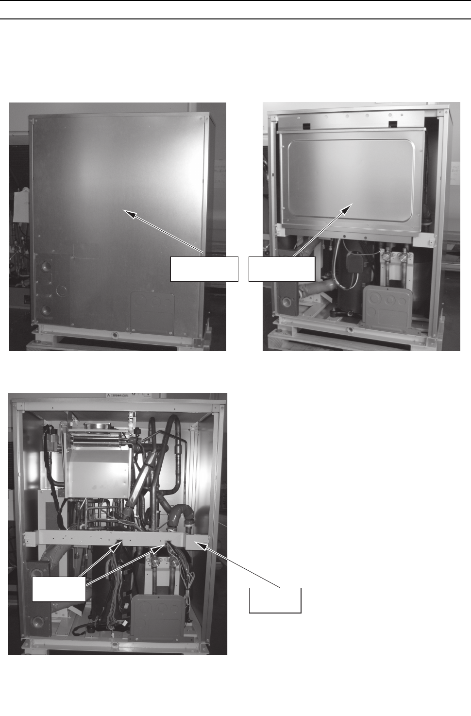
[ IX Troubleshooting ]
- 347 -
HWE09080 GB
[6] Compressor Replacement Instructions
1. Compressor Replacement Instructions
Follow the procedures below (Steps 1 through 5) to remove the compressor components and replace the compressor.
Reassemble them in the reverse order after replacing the compressor.
1. Remove the service panel (front panels).
3. Remove the wires that are secured to the frame,
and remove the frame.
Electric
wiring
Frame
Service panel Control box
2. Remove the control box.
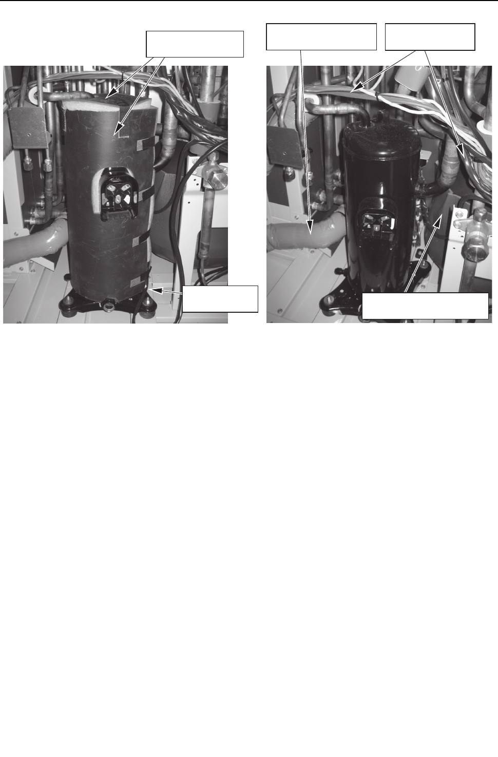
[ IX Troubleshooting ]
- 348 -
HWE09080 GB
Remove the insulation material and the belt heater
from the compressor.
First, move the nearby wiring, insulation material on
the accumulator, and pipe covers on the pipe and
water heat exchanger out of the way or protect them
from the brazing flame; then debraze the pipe, and
replace the compressor.
Acoustic insulation
on the compressor
Thermal insulation
on the accumulator
Pipe cover on the
water heat exchanger
Belt heater
Wiring adjacent to
the compressor
4. 5.
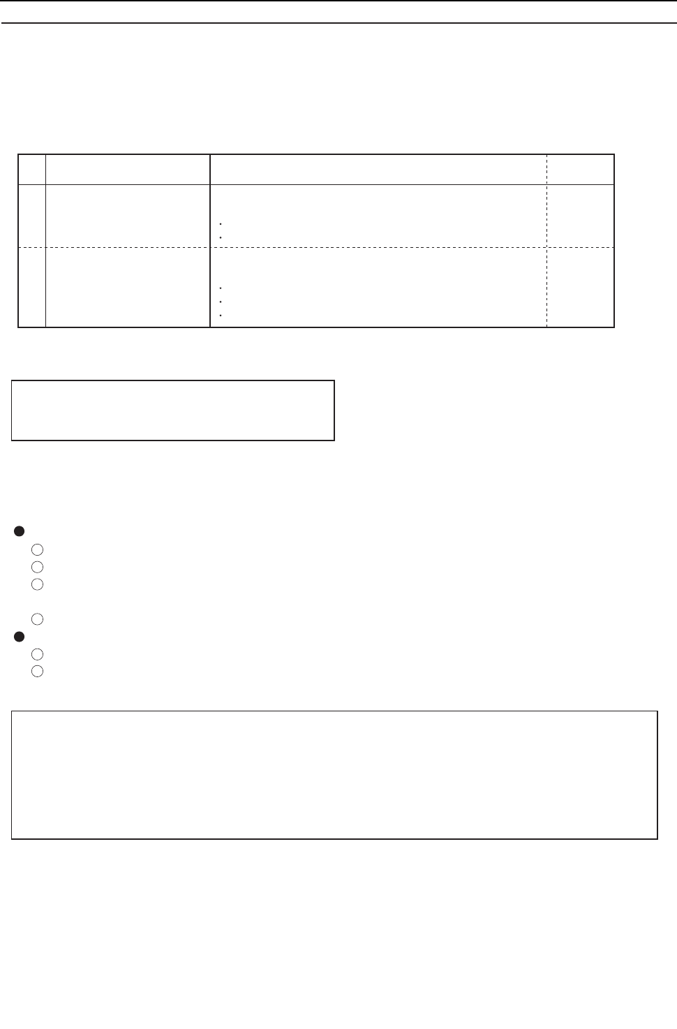
[ IX Troubleshooting ]
- 349 -
HWE09080 GB
No. Parts to be replaced
1 Water-cooled heat
exchanger assembly
2 Check valve (CV8)
1. Water heat exchanger assembly and check valve (CV8) replacement instructions
* The following describes the procedures for replacing the water heat exchanger assembly and check valve (CV8).
1. Applicable models
• PQHY-P72, 96, 120YHMU-A
• PQRY-P72, 96, 120YHMU-A
2. Parts to be serviced, Set-contents
Required materials
Water-cooled heat exchanger service parts kit
[Kit contents]
Instructions sheet
Water-cooled heat exchanger assembly
Check valve service parts kit
[Kit contents]
Instructions sheet
Check valve assmbly
Connecting pipe
Qty.
1 kit
1
1
1 kit
1
1
1
3. Procedures
* Precautions for starting replacement
• Check that the main power supply is OFF.
• Check that no refrigerant is in the heat source unit.
Remove each part according to the 1)-3) procedures on the next page before replacing service parts.
Mount the removed parts back in place in a reversed procedures of 1)-3) on the next page after replacing service
parts.
(1) Water-cooled heat exchanger assembly replacement procedures
Removal procedures
Remove the duct, solenoid valve block support, and INV heat exchanger support.
Hand the solenoid valve block support with wire from the beam so that it will not fall.
Remove the fastening plate and the screws holding the water-cooled heat exchanger, and
remove the braze
Pull the water-cooled heat exchanger forward toward the front of the unit.
Installation procedures
Install the water-cooled heat exchanger included in the replacement parts kit
Reinstall the fastening plate, fixing screws, INV heat exchanger support, solenoid valve block
support, and the duct.
* Precautions for replacing water-cooled heat exchanger assembly
• Be sure to perform no-oxidation brazing when brazing.
• After brazing, check the condition around the brazing. After confirming no leakage, evacuate the air
inside. (*1)
• Perform brazing with care of the flame direction so that it does not burn cables and plates etc. in the unit.
*1: Refer to Chapter I [8] Vacuum Drying (Evacuation) for detailed procedure.
1
2
3
4
6
7
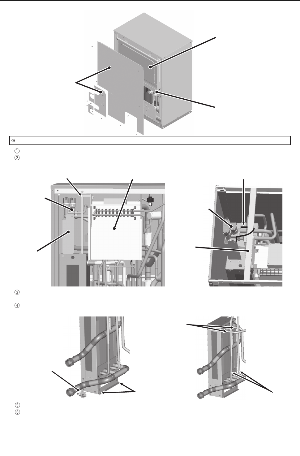
[ IX Troubleshooting ]
- 350 -
HWE09080 GB
1) Remove the service
panel and the water pipe
inlet/outlet panel.
2) Disconnect all wires inside the
control box, and remove the
control box.
3) Remove Frame M under the
control box.
Suspend the solenoid valve block
from the beam with wire.
Solenoid
valve block
Solenoid
valve block
INV heat exchanger support Duct
Solenoid valve
block support
2 fixing screws
Water heat exchanger
mounting bracket
(2 screws)
Debraze the sections here.
Debraze the sections here.
Beam
If the compressor is accessible by removing the rear service panel, it may facilitate compressor replacement.
Remove the duct, solenoid valve block support, and INV heat exchanger support.
Pull the water heat exchanger out forward.
Suspend the solenoid valve block from the beam with wire so it will not fall. (Refer to the figure below at right. )
Remove the water heat exchanger mounting bracket and the fixing screws (figure below at left), and debraze
the sections indicated with arrows in the figure below at right.
Install the replacement water heat exchanger.
Reinstall the mounting bracket, fixing screws, INV heat exchanger support, solenoid valve block support, and
duct as they were.
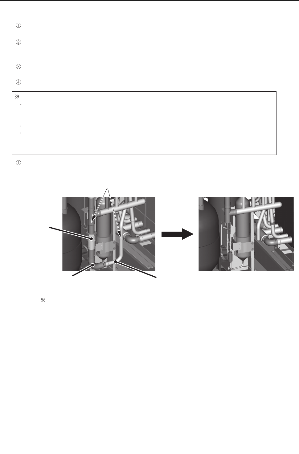
[ IX Troubleshooting ]
- 351 -
HWE09080 GB
(2) Replacement procedures for check valve assembly
● Removing the check valve assembly
Remove the check valve (CV8), elbow, and the pipe shown in the figure below at left by removing the brazing flux
from the sections that are indicated with arrows.
Check the shape of the water heat exchanger pipe end. Depending on its shape, the pipe end needs to be cut.
When cutting the pipe end, keep burrs from entering the refrigerant circuit.
● Installing the check valve assembly
Install the replacement check valve assembly on the unit.
Depending on the shape of the pipe end, the connecting pipe needs to be brazed to the pipe.
Screw the screws back on.
Remove the brazing flux. (2 places)
Remove the check valve (CV8), elbow, and the pipe shown in the figure below at left by removing the
brazing flux from the sections that are indicated with arrows.
Check valve (CV8)
Elbow
Before removal
Section of the pipe to
be removed After removal
Notes on replacing the check valve assembly
Braze the pipes under a nitrogen purge to prevent oxidation.
Before heating the pipes, place a wet towel on the check valve to keep its temperature
below 120°C [248°F].
After brazing the pipes, check for leaks, and evacuate the air from the pipes. (*1)
Direct the flame away from the cables and sheet metals inside the unit so as not to burn
them.
*1 Refer to Chapter I [8] Vacuum Drying (Evacuation) for details.
The figures above are the views from behind to present a better view of the section to be removed.
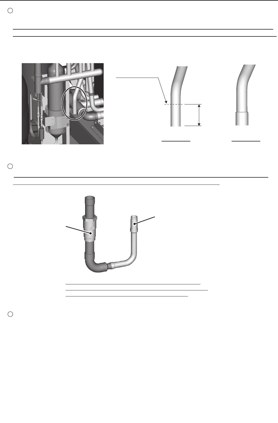
[ IX Troubleshooting ]
- 352 -
HWE09080 GB
*A connecting pipe is required only when the pipe section
that is circled in the figure above looks like the one shown in
the figure above in the middle entitled "Pipe type A."
Cut the pipe here.
Check valve assembly
Connecting pipe
Pipe type A Pipe type B
3 Install the replacement check valve assembly on the unit.
When connecting the check valve assembly to the type of pipe shown in the figure above in the middle, braze
the connecting pipe that is included in the service parts kit to the check valve assembly.
4 Screw the screws back on.
36mm
2 Depending on the manufacturing period, the section of the pipe that is circled in the figure below at left (after the brazing
flux is removed) comes in two types.
If the pipe end looks like the one in the figure below in the middle (Pipe type A), cut off 36 mm of the pipe at the
end. If the pipe end looks like the one in the figure below at right (Pipe type B), the pipe end needs not be cut off.
When cutting the pipe end, keep burrs from entering the refrigerant circuit.
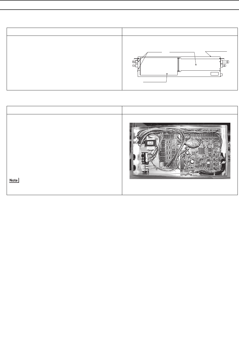
[ IX Troubleshooting ]
- 353 -
HWE09080 GB
[7] Servicing the BC controller
1. Service panel
2. Control box
*Special care must be taken when replacing heavy parts.
Work procedure Explanatory figure
1) Remove the two lock nuts on the control box, loosen the
other two, and remove the control box.
2) Remove the three fixing screws on the service panel,
and remove the service panel.
3) Remove the nine machine screws on the ceiling panel,
and remove the ceiling panel.
Work procedure Explanatory figure
(1) To check the inside of the control box, remove the
two lock nuts on the control box cover.
1) Check the terminal connection of the power wire or of
the transmission line.
2) Check the transformer.
3) Check the address switch.
(2) When the control board is replaced, the followings
must be noted.
(1) Check that the board type is G,GA, or GB(HB).
(2) Check that the wire and the connector are properly con-
nected.
It is not required to remove the two fixing screws on the
control box when checking the inside.
Loosen Service panel
Control Box
Ceiling panel
CMB-1016NU-G, GA
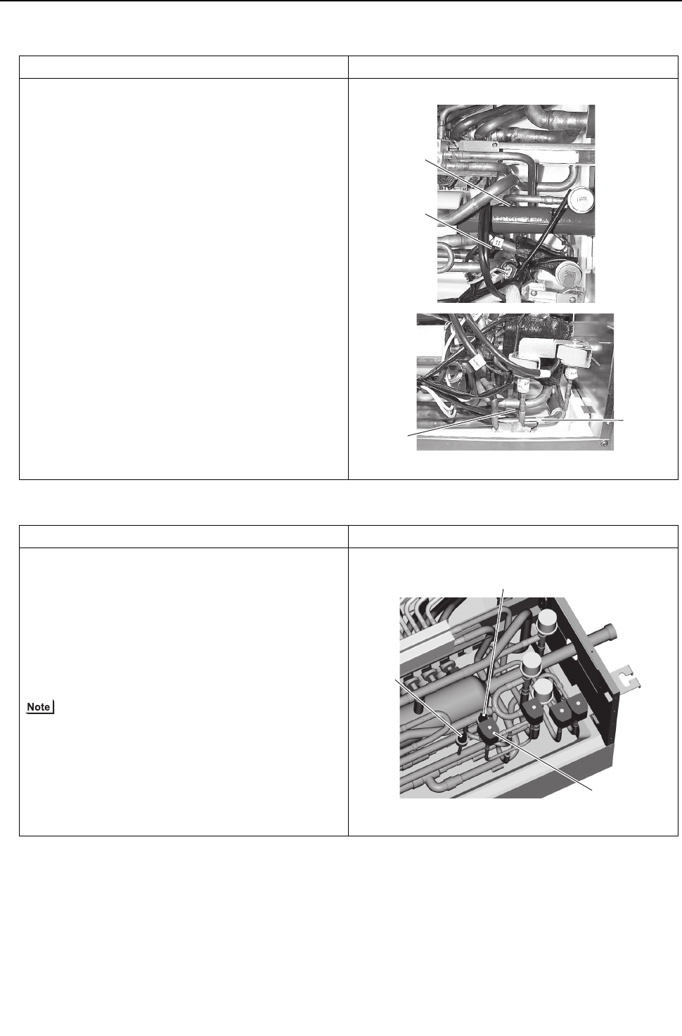
[ IX Troubleshooting ]
- 354 -
HWE09080 GB
3. Thermistor (liquid pipe/gas pipe temperature detection)
4. Pressure sensor
*Special care must be taken when replacing heavy parts.
Work procedure Explanatory figure
(1) Remove the service panel.
1) For TH11, TH12, and TH15, refer to 1. 1) - 2).
2) For TH16, refer to 1. 1) - 3) (GA type only)
(2) Remove the lead wire of the piping sensor from the
control board.
1) TH11,TH12 (CN10)
2) TH15,TH16 (CN11)
(3) Pull out the temperature sensor from the tempera-
ture sensor housing, and replace the temperature
sensor with the new one.
(4) Connect the lead wire of the temperature sensor se-
curely on the control board.
Work procedure Explanatory figure
(1) Remove the service panel.
1) For the pressure sensors PS1 and PS3, refer to 1. 1) - 2)
(2) Remove the pressure sensor connector in trouble
from the control board, and insulate the connector.
1) Liquid-side pressure sensor (CNP1)
2) Intermediate-part pressure sensor (CNP3)
(3) Attach a new pressure sensor to the place which is
shown in the figure, and insert the connector to the
control board.
When gas leaks from the pressure sensor, repair the
leak, and follow the instructions above if required.
CMB-1016NU-GA
TH16
TH11
TH15
TH12
SVM1
PS1
PS3
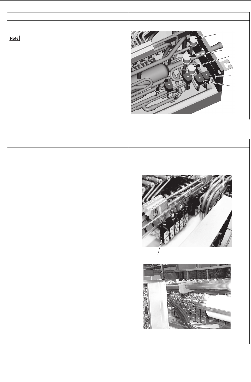
[ IX Troubleshooting ]
- 355 -
HWE09080 GB
5. LEV
6. Solenoid valve
Work procedure Explanatory figure
(1) Remove the service panel.(Refer to 1. 1) - 3)
(2) Replace the LEV in trouble.
Secure enough service space in the ceiling for welding
operation, and conduct the work carefully.If required,
dismount the unit from the ceiling, and conduct the work.
*Special care must be taken when replacing heavy parts.
Work procedure Explanatory figure
(1) Remove the service panel.(Refer to 1. 1) - 3)
(2) Remove the connector of the solenoid valve in trou-
ble.
(3) Remove the solenoid valve coil.
1) The coils on the solenoid valves SVA, SVB, SVM1 and
SVM2 can be serviced through the inspection door. SVC
is accessible for replacement by removing the four
mounting screws on the rear panel and removing the
panel (if enough space is available on the back). (SVM1
is present only on the G and GA types, SVM2 on the GA
type.)
LEV3
LEV1
LEV2
SVM2
SVM2b
CMB-1016NU-G
Double-pipe heat exchanger
CMB-1016NU-GA
Solenoid valve

[ IX Troubleshooting ]
- 356 -
HWE09080 GB
[8] Troubleshooting Using the Heat source Unit LED Error Display
If the LED error display appear as follows while all the SW1 switches are set to OFF, check the items under the applicable item
numbers below.
1. Error code appears on the LED display.
Refer to IX [2] Responding to Error Display on the Remote Controller.(page 230)
2. LED is blank.
Take the following troubleshooting steps.
(1) If the voltage between pins 1 and 3 of CNDC on the control board is outside the range between 220 VDC and 380 VDC,
refer to IX [4] -7- (2) Troubleshooting transmission power circuit of heat source unit.
(2) If the LED error display becomes lit when the power is turned on with all the connectors on the control board except
CNDC disconnected, there is a problem with the wiring to those connectors or with the connectors themselves.
(3) If nothing appears on the display under item (2) above AND the voltage between pins 1 and 3 of CNDC is within the
range between 220 VDC and 380 VDC, control board failure is suspected.
3. Only the software version appears on the LED display.
(1) Only the software version appears while the transmission cables to TB3 and TB7 are disconnected.
1) Wiring failure between the control board and the transmission line power supply board.(CNIT, CNS2, CN102)
2) If item 1) checks out OK, the transmission line power supply board failure is suspected.
3) If items 1) and 2) check out OK, control board failure is suspected.
(2) If the LED display appears as noted in "X [1] 2. LED display at Initial setting" (page 359)while the transmission cables
to TB3 and TB7 are disconnected, failure with the transmission cable or the connected equipment is suspected.

- 357 -
HWE09080 GB
X
LED Monitor Display on the Heat source Unit Board
[1] How to Read the LED on the Service Monitor ............................................................... 359

- 358 -
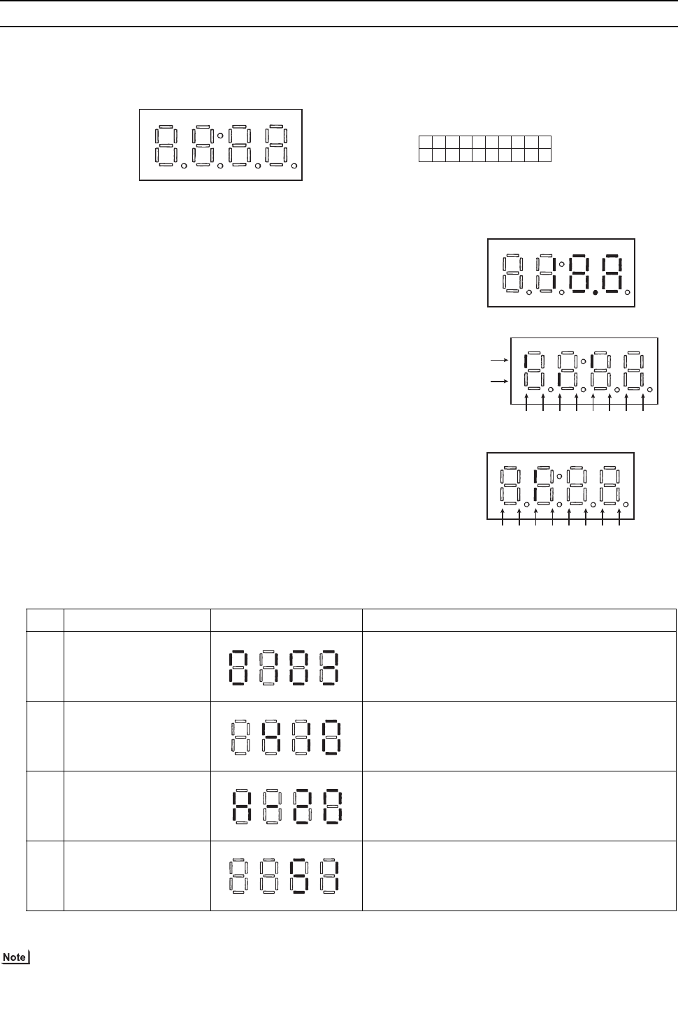
[ X LED Monitor Display on the Heat source Unit Board ]
- 359 -
HWE09080 GB
X LED Monitor Display on the Heat source Unit Board
[1] How to Read the LED on the Service Monitor
1. How to read the LED
By setting the DIP SW 1-1 through 1-10 (Switch number 10 is represented by 0), the operating condition of the unit can be
monitored on the service monitor. (Refer to the table on the following pages for DIP SW settings.)
The service monitor uses 4-digit 7-segment LED to display numerical values and other types of information.
Pressure and temperature are examples of numerical values, and operating conditions and the on-off status of solenoid valve
are examples of flag display.
2. LED display at initial setting
From power on until the completion of initial settings, the following information will be displayed on the monitor screen.
(Displays No. 1 through No. 4 in order repeatedly.)
After the initial settings have been completed, the information on these items can be checked by making the switch setting
that corresponds to No. 517 in the LED display table.
Only item No. 1 "Software Version" appears on the display if there is a wiring failure between the control board and the trans-
mission line power supply board or if the circuit board has failed.
1) Display of numerical values
Example: When the pressure data sensor reads 18.8kg/cm2 (Item No. 58)
The unit of pressure is in kg/cm2
Use the following conversion formula to convert the displayed value into
a value in SI unit.
Value in SI unit (MPa) = Displayed value (kg/cm2) x 0.098
2) Flag display
Example: When 21S4a, 21S4b, SV1a are ON. (Item No. 3)
Example: 3-minutes restart mode (Item No. 14)
No Item Display Remarks
1
Software version
[0103] : Version 1.03
2
Refrigerant type
[ 410] : R410A
3
Model and capacity [H-20] : Cooling/Heating 20 HP
For the first few minutes after power on, the capacity of
each heat source unit is displayed. Thereafter, the
combined capacity is displayed.
4
Communication address
[ 51] : Address 51
SW1
ON
12345678
SW1-10 is represented as “0” in the table.
910
7SEG LED
LD1 LD2 LD3 LD4 LD5 LD6 LD7 LD8
Upper
Lower
LD1 LD2 LD3 LD4 LD5 LD6 LD7 LD8
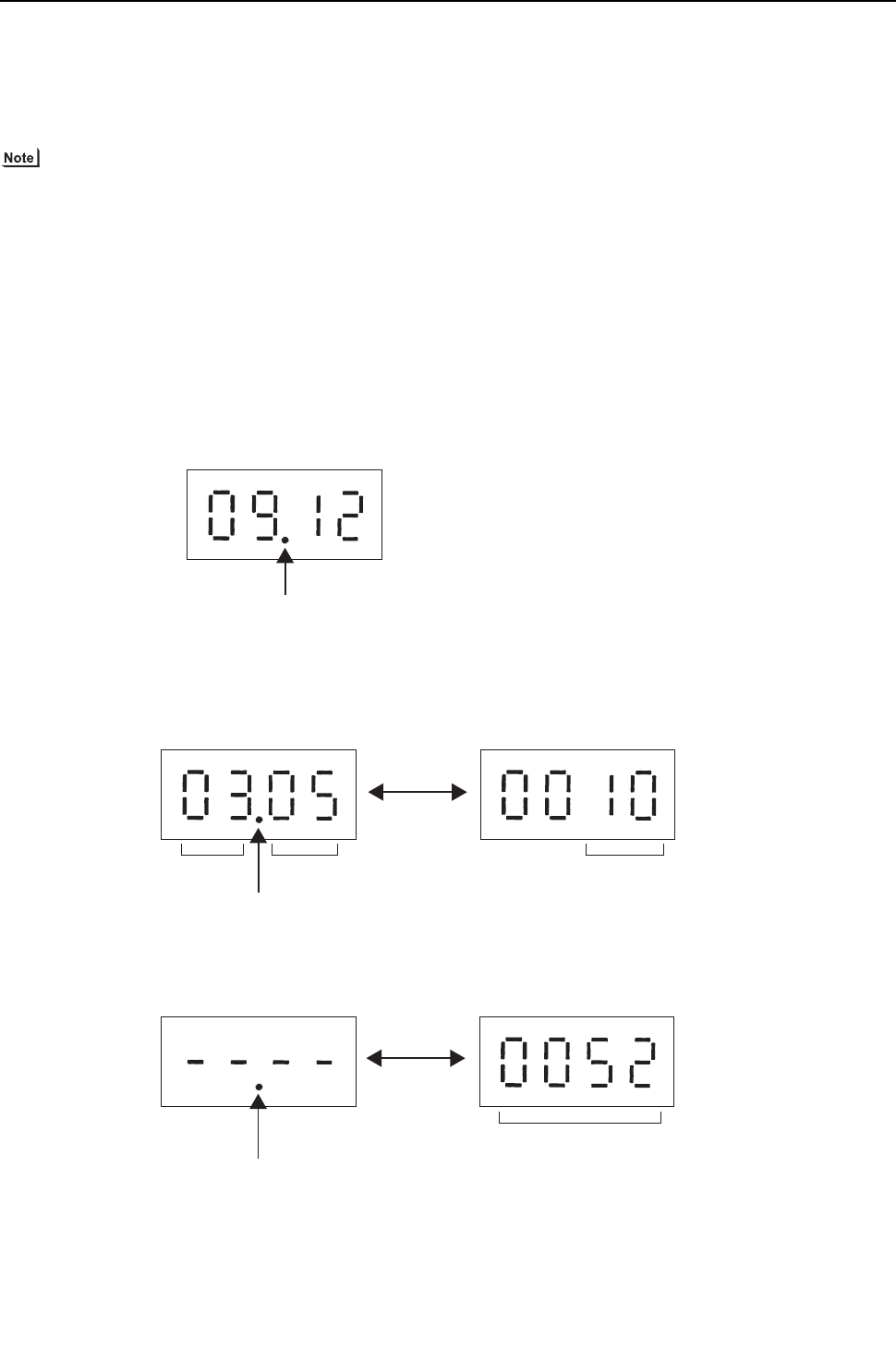
[ X LED Monitor Display on the Heat source Unit Board ]
- 360 -
HWE09080 GB
3. Time data storage function
The heat source unit has a simple clock function that enables the unit to calculate the current time with an internal timer by
receiving the time set by the system controller, such as G(B)-50A.
If an error (including a preliminary error) occurs, the error history data and the error detection time are stored into the service
memory.
The error detection time stored in the service memory and the current time can be seen on the service LED.
1) Use the time displayed on the service LED as a reference.
2) The date and the time are set to "00" by default. If a system controller that sets the time, such as G(B)-50A is not connected,
the elapsed time and days since the first power on will be displayed.
If the time set on a system controller is received, the count will start from the set date and the time.
3) The time is not updated while the power of the heat source unit is turned off. When the power is turned off and then on again,
the count will resume from the time before the power was turned off. Thus, the time that differs the actual time will be displayed.
(This also applies when a power failure occurs.)
The system controller, such as G(B)-50A, adjusts the time once a day. When the system controller is connected, the time will
be automatically updated to the correct current time after the time set by the system controller is received. (The data stored
into the memory before the set time is received will not be updated.)
(1) Reading the time data:
1) Time display
Example: 12 past 9
2) Date display
When the main controller that can set the time is connected
Example: May 10, 2003
When the main controller that can set the time is not connected
Example: 52 days after power was turned on
* Disappears if the time data is deviated due to a power failure, or if a
system controller that sets the time is not connected.
Alternate display
Alternate display of year and month, and date
* Appears between the year and the month, and nothing appears
when the date is displayed.
Alternate display
Day count
* Appears between the year and the month, and nothing
appears when the date is displayed.
[ X LED Monitor Display on the Heat source Unit Board ]
- 361 -
HWE09080
XLED Monitor Disp lay on the Heat s ource Unit Board
LED monitor display
Current data
No.
SW1
Item
Display Unit
(A, B) *1 Remarks
1234567890 LD1 LD2 LD3 LD4 LD5 LD6 LD7 LD8 OC OS
0 0000000000
Relay output display 1
Lighting
Comp in op-
eration 72C OC CPU in oper-
ation AA
Check (error) display 1
OC/OS error 0000 to 9999 (Address and error codes highlighted) B B
1 1000000000
Check (error) display 2
OC/OS error
0000 to 9999 (Address and error codes highlighted) A A
Display of the latest pre-
liminary error
If no preliminary errors
are detected, "----" ap-
pears on the display.
2 0100000000
Check (error) display 3
(Including IC and BC) 0000 to 9999 (Address and error codes highlighted) B
If no errors are detected,
"----" appears on the dis-
play.
3 1100000000
Relay out-
put display
2
Top 21S4a CH11 SV1a
AA
Bottom
4 0010000000
Relay out-
put display
3
Top
SV4a SV4b SV4d SV9
Power sup-
ply for indoor
transmis-
sion line AA
Bottom SV7a SV7b
5 1010000000
6 0110000000
7 1110000000
Special control
Retry opera-
tion
Emergency
operation
Communica-
tion error be-
tween the
OC and OS
Communica-
tion error
3-minute re-
start delay
mode
BB
8 0001000000
9 1001000000
Communication de-
mand capacity 0000 to 9999 B
If not demanded con-
trolled, "----" [ % ] ap-
pears on the display.
10 0101000000
Contact point demand
capacity 0000 to 9999 B
If not demanded con-
trolled, "----" [ % ] ap-
pears on the display.
*1 A: The condition of either OC or OS is displayed individually. B: The condition of the entire refrigerant system is displayed.

[ X LED Monitor Display on the Heat source Unit Board ]
- 362 -
HWE09080
11 1101000000
External signal
(Open input contact
point)
Contact
point de-
mand
Low-noise
mode
(Capacity
priority )
Cooling-
heating
changeover
(Cooling)
Cooling-
heating
changeover
(Heating)
AA
12 0011000000
External signal
(Open input contact
point)
Pump inter-
lock (Con-
tact: open)
Low-noise
mode
(Quiet priori-
ty)
AA
13 1011000000
14 0111000000
Heat source unit opera-
tion status BC opera-
tion signal
3-minutes
restart mode
Compressor
in operation
Preliminary
error Error
3-minutes
restart after
instanta-
neous power
failure
Preliminary
low pres-
sure error
AA
15 1111000000 OC/OS identification OC/OS A A
16 0000100000
Indoor unit
check
Top Unit No. 1 Unit No. 2 Unit No. 3 Unit No. 4 Unit No. 5 Unit No. 6 Unit No. 7 Unit No. 8 B The lamp that corre-
sponds to the unit that
came to an abnormal stop
lights.
The lamp goes off when
the error is reset.
Each unit that comes to
an abnormal unit will be
given a sequential num-
ber in ascending order
starting with 1.
Bottom Unit No. 9 Unit No. 10 Unit No. 11 Unit No. 12 Unit No. 13 Unit No. 14 Unit No. 15 Unit No. 16
17 1000100000
Top Unit No. 17 Unit No. 18 Unit No. 19 Unit No. 20 Unit No. 21 Unit No. 22 Unit No. 23 Unit No. 24
Bottom Unit No. 25 Unit No. 26 Unit No. 27 Unit No. 28 Unit No. 29 Unit No. 30 Unit No. 31 Unit No. 32
18 0100100000
Top Unit No. 33 Unit No. 34 Unit No. 35 Unit No. 36 Unit No. 37 Unit No. 38 Unit No. 39 Unit No. 40
Bottom Unit No. 41 Unit No. 42 Unit No.43 Unit No. 44 Unit No. 45 Unit No. 46 Unit No47 Unit No. 48
19 1100100000
Top Unit No. 49 Unit No. 50
Bottom
20 0010100000
Indoor unit
Operation
mode
Top Unit No. 1 Unit No. 2 Unit No. 3 Unit No. 4 Unit No. 5 Unit No. 6 Unit No. 7 Unit No. 8 B Lit during cooling
Lit during heating
Unlit while the unit is
stopped or in the fan
mode
Bottom Unit No. 9 Unit No. 10 Unit No. 11 Unit No. 12 Unit No. 13 Unit No. 14 Unit No. 15 Unit No. 16
21 1010100000
Top Unit No. 17 Unit No. 18 Unit No. 19 Unit No. 20 Unit No. 21 Unit No. 22 Unit No. 23 Unit No. 24
Bottom Unit No. 25 Unit No. 26 Unit No. 27 Unit No. 28 Unit No. 29 Unit No. 30 Unit No. 31 Unit No. 32
22 0110100000
Top Unit No. 33 Unit No. 34 Unit No. 35 Unit No. 36 Unit No. 37 Unit No. 38 Unit No. 39 Unit No. 40
Bottom Unit No. 41 Unit No. 42 Unit No.43 Unit No. 44 Unit No. 45 Unit No. 46 Unit No47 Unit No. 48
23 1110100000
Top Unit No. 49 Unit No. 50
Bottom
Current data
No.
SW1
Item
Display Unit
(A, B) *1 Remarks
1234567890 LD1 LD2 LD3 LD4 LD5 LD6 LD7 LD8 OC OS
*1 A: The condition of either OC or OS is displayed individually. B: The condition of the entire refrigerant system is displayed.

[ X LED Monitor Display on the Heat source Unit Board ]
- 363 -
HWE09080
24 0001100000
Indoor unit
thermo-
stat
Top Unit No. 1 Unit No. 2 Unit No. 3 Unit No. 4 Unit No. 5 Unit No. 6 Unit No. 7 Unit No. 8 B Lit when thermostat is on
Unlit when thermostat is
off
Bottom Unit No. 9 Unit No. 10 Unit No. 11 Unit No. 12 Unit No. 13 Unit No. 14 Unit No. 15 Unit No. 16
25 1001100000
Top Unit No. 17 Unit No. 18 Unit No. 19 Unit No. 20 Unit No. 21 Unit No. 22 Unit No. 23 Unit No. 24
Bottom Unit No. 25 Unit No. 26 Unit No. 27 Unit No. 28 Unit No. 29 Unit No. 30 Unit No. 31 Unit No. 32
26 0101100000
Top Unit No. 33 Unit No. 34 Unit No. 35 Unit No. 36 Unit No. 37 Unit No. 38 Unit No. 39 Unit No. 40
Bottom Unit No. 41 Unit No. 42 Unit No.43 Unit No. 44 Unit No. 45 Unit No. 46 Unit No47 Unit No. 48
27 1101100000
Top Unit No. 49 Unit No. 50
Bottom
28 0011100000
29 1011100000
30 0111100000
31 1111100000
32 0000010000
33 1000010000
34 0100010000
35 1100010000
36 0010010000
37 1010010000 BC operation mode Cooling-only
ON
Cooling-only
OFF
Heating-only
ON
Heating-only
OFF
Mixed-mode
ON
Mixed-mode
OFF Fan Stop B
38 0110010000
39 1110010000 Heat source unit Opera-
tion mode
Permissible
stop Standby Cooling Cooling-
main Heating Heating-
main AA
40 0001010000
41 1001010000
42 0101010000
Heat source unit control
mode Stop Thermo OFF Abnormal
stop
Scheduled
control
Initial start
up Defrost Oil balance
Low fre-
quency oil
recovery
AA
43 1101010000 Refrigerant
recovery AA
44 0011010000
Current data
No.
SW1
Item
Display Unit
(A, B) *1 Remarks
1234567890 LD1 LD2 LD3 LD4 LD5 LD6 LD7 LD8 OC OS
*1 A: The condition of either OC or OS is displayed individually. B: The condition of the entire refrigerant system is displayed.

[ X LED Monitor Display on the Heat source Unit Board ]
- 364 -
HWE09080
45 1011010000 TH4 -99.9 to 999.9 A A The unit is [°C]
46 0111010000 TH3 -99.9 to 999.9 A A
47 1111010000 TH7 -99.9 to 999.9 A A
48 0000110000 TH6 -99.9 to 999.9 A A
49 1000110000 TH2 -99.9 to 999.9 A A
50 0100110000 TH5 -99.9 to 999.9 A A
51 1100110000 TH8 -99.9 to 999.9 A A
52 0010110000
53 1010110000 THINV -99.9 to 999.9 A A Unit in [°C]
54 0110110000
55 1110110000
56 0001110000 THHS1 -99.9 to 999.9 A A The unit is [°C]
57 1001110000 THBOX -99.9 to 999.9 A A
58 0101110000 High-pressure sensor
data -99.9 to 999.9 A A The unit is [kgf/cm2]
59 1101110000 Low-pressure sensor
data -99.9 to 999.9 A A
60 0011110000
61 1011110000
62 0111110000
63 1111110000
64 0000001000
65 1000001000
66 0100001000
67 1100001000
68 0010001000
69 1010001000
70 0110001000
71 1110001000
Current data
No.
SW1
Item
Display Unit
(A, B) *1 Remarks
1234567890 LD1 LD2 LD3 LD4 LD5 LD6 LD7 LD8 OC OS
*1 A: The condition of either OC or OS is displayed individually. B: The condition of the entire refrigerant system is displayed.

[ X LED Monitor Display on the Heat source Unit Board ]
- 365 -
HWE09080
72 0001001000
73 1001001000
74 0101001000
75 1101001000
76 0011001000
77 1011001000
78 0111001000 Qj 0000 to 9999 B B
79 1111001000 Qjc 0000 to 9999 B B
80 0000101000 Qjh 0000 to 9999 B B
81 1000101000 Target Tc -99.9 to 999.9 B The unit is [°C]
82 0100101000 Target Te -99.9 to 999.9 B
83 1100101000 Tc -99.9 to 999.9 A A
84 0010101000 Te -99.9 to 999.9 A A
85 1010101000
86 0110101000 Total frequencies
(OC+OS) 0000 to 9999 B Control data [ Hz ]
87 1110101000 Total frequency of each
unit 0000 to 9999 A A
88 0001101000 COMP frequency 0000 to 9999 A A
89 1001101000
90 0101101000
91 1101101000
Comp operating fre-
quency
0000 to 9999 A A
Unit in [rsp]
The inverter output current
(voltage) frequency will
equal the integer multiples
of the operating frequency
of the compressor.
92 0011101000
93 1011101000 All AK (OC+OS) 0000 to 9999 B
94 0111101000 AK 0000 to 9999 A A
95 1111101000
Current data
No.
SW1
Item
Display Unit
(A, B) *1 Remarks
1234567890 LD1 LD2 LD3 LD4 LD5 LD6 LD7 LD8 OC OS
*1 A: The condition of either OC or OS is displayed individually. B: The condition of the entire refrigerant system is displayed.

[ X LED Monitor Display on the Heat source Unit Board ]
- 366 -
HWE09080
96 0000011000
97 1000011000
98 0100011000
99 1100011000
100 0010011000
101 1010011000
102 0110011000 LEVINV 0 to 480 A A Heat source unit LEV
opening (Fully open: 480)
103 1110011000 LEV1 0 to 480 A A Heat source unit LEV
opening (Fully open: 480)
104 0001011000
LEV2
60 to 1400 A A
Heat source unit LEV
opening (Fully open:
1400)
105 1001011000
106 0101011000
107 1101011000
108 0011011000 COMP operating cur-
rent (DC) 00.0 to 999.9 A A Peak value[A]
109 1011011000
110 0111011000
111 1111011000 COMP bus voltage 00.0 to 999.9 A A The unit is
[ V ]
112 0000111000
113 1000111000
114 0100111000
115 1100111000
116 0010111000
Number of times the
unit went into the mode
to remedy wet vapor
suction
0000 to 9999 B
Current data
No.
SW1
Item
Display Unit
(A, B) *1 Remarks
1234567890 LD1 LD2 LD3 LD4 LD5 LD6 LD7 LD8 OC OS
*1 A: The condition of either OC or OS is displayed individually. B: The condition of the entire refrigerant system is displayed.
[ X LED Monitor Display on the Heat source Unit Board ]
- 367 -
HWE09080
117 1010111000 COMP Operation time
Upper 4 digits 0000 to 9999 A A The unit is
[ h ]
118 0110111000 COMP Operation time
Lower 4 digits 0000 to 9999 A A
119 1110111000
120 0001111000
121 1001111000
Backup mode Abnormal
pressure rise
High-pres-
sure drop
Low-pres-
sure drop
Abnormal Td
rise
Control box
temperature
rise
AA
Stays lit for 90 seconds
after the completion of
backup control
122 0101111000
123 1101111000
COMP number of start-
stop events
Upper 4 digits
0000 to 9999 A A
Count-up at start-up
The unit is [Time]
124 0011111000
COMP number of start-
stop events
Lower 4 digits
0000 to 9999 A A
125 1011111000
126 0111111000
127 1111111000
128 0000000100
129 1000000100
Integrated operation
time of compressor (for
rotation purpose)
0000 to 9999 B
The unit is [ h ]
130 0100000100
131 1100000100
Current data
No.
SW1
Item
Display Unit
(A, B) *1 Remarks
1234567890 LD1 LD2 LD3 LD4 LD5 LD6 LD7 LD8 OC OS
*1 A: The condition of either OC or OS is displayed individually. B: The condition of the entire refrigerant system is displayed.

[ X LED Monitor Display on the Heat source Unit Board ]
- 368 -
HWE09080
132 0010000100
Relay out-
put display
BC(Main)
Top SVM1 SVM2 SVM1b SVM2b
B
Bottom
133 1010000100
Top SVA1 SVB1 SVC1 SVA2 SVB2 SVC2
B
Bottom SVA3 SVB3 SVC3 SVA4 SVB4 SVC4
134 0110000100
Top SVA5 SVB5 SVC5 SVA6 SVB6 SVC6
B
Bottom SVA7 SVB7 SVC7 SVA8 SVB8 SVC8
135 1110000100
Top SVA9 SVB9 SVC9 SVA10 SVB10 SVC10
B
Bottom SVA11 SVB11 SVC11 SVA12 SVB12 SVC12
136 0001000100
Top SVA13 SVB13 SVC13 SVA14 SVB14 SVC14
B
Bottom SVA15 SVB15 SVC15 SVA16 SVB16 SVC16
137 1001000100
138 0101000100
Relay out-
put display
BC(Sub1)
Top SVA1 SVB1 SVC1 SVA2 SVB2 SVC2
B
Bottom SVA3 SVB3 SVC3 SVA4 SVB4 SVC4
139 1101000100
Top SVA5 SVB5 SVC5 SVA6 SVB6 SVC6
B
Bottom SVA7 SVB7 SVC7 SVA8 SVB8 SVC8
140 0011000100
Top SVA9 SVB9 SVC9 SVA10 SVB10 SVC10
B
Bottom SVA11 SVB11 SVC11 SVA12 SVB12 SVC12
141 1011000100
Top SVA13 SVB13 SVC13 SVA14 SVB14 SVC14
B
Bottom SVA15 SVB15 SVC15 SVA16 SVB16 SVC16
142 0111000100
Current data
No.
SW1
Item
Display Unit
(A, B) *1 Remarks
1234567890 LD1 LD2 LD3 LD4 LD5 LD6 LD7 LD8 OC OS
*1 A: The condition of either OC or OS is displayed individually. B: The condition of the entire refrigerant system is displayed.

[ X LED Monitor Display on the Heat source Unit Board ]
- 369 -
HWE09080
143 1111000100
Relay out-
put display
BC(Sub2)
Top SVA1 SVB1 SVC1 SVA2 SVB2 SVC2
B
Bottom SVA3 SVB3 SVC3 SVA4 SVB4 SVC4
144 0000100100
Top SVA5 SVB5 SVC5 SVA6 SVB6 SVC6
B
Bottom SVA7 SVB7 SVC7 SVA8 SVB8 SVC8
145 1000100100
Top SVA9 SVB9 SVC9 SVA10 SVB10 SVC10
B
Bottom SVA11 SVB11 SVC11 SVA12 SVB12 SVC12
146 0100100100
Top SVA13 SVB13 SVC13 SVA14 SVB14 SVC14
B
Bottom SVA15 SVB15 SVC15 SVA16 SVB16 SVC16
147 1100100100
148 0010100100
149 1010100100 BC(Main or standard)
TH11 -99.9 to 999.9 B
150 0110100100 BC(Main)TH12 -99.9 to 999.9 B
151 1110100100 BC(Main)TH15 -99.9 to 999.9 B
152 0001100100 BC(Main)TH16 -99.9 to 999.9 B
153 1001100100 BC(Main)PS1 -99.9 to 999.9 B
154 0101100100 BC(Main)PS3 -99.9 to 999.9 B
155 1101100100 BC(Main)SC11 -99.9 to 999.9 B
156 0011100100 BC(Main)SH12 -99.9 to 999.9 B
157 1011100100 BC(Main)SH13 -99.9 to 999.9 B
158 0111100100 BC(Main)SC16 -99.9 to 999.9 B
159 1111100100 BC(Main)LEV1 0000 to 2000 B LEV1 opening
(Fully open:2000)
160 0000010100 BC(Main)LEV3 0000 to 2000 B LEV3 opening
(Fully open:2000)
161 1000010100 BC(Sub1)TH12 -99.9 to 999.9 B
162 0100010100 BC(Sub1)TH15 -99.9 to 999.9 B
163 1100010100 BC(Sub1)LEV3 0000 to 2000 B LEV3a opening
(Fully open:2000)
Current data
No.
SW1
Item
Display Unit
(A, B) *1 Remarks
1234567890 LD1 LD2 LD3 LD4 LD5 LD6 LD7 LD8 OC OS
*1 A: The condition of either OC or OS is displayed individually. B: The condition of the entire refrigerant system is displayed.

[ X LED Monitor Display on the Heat source Unit Board ]
- 370 -
HWE09080
164 0010010100 BC(Sub2)TH12 -99.9 to 999.9 B
165 1010010100 BC(Sub2)TH25 -99.9 to 999.9 B
166 0110010100 BC(Sub2)LEV3 0000 to 2000 B LEV3a opening
(Fully open:2000)
167 1110010100 BC(Main)LEV2 0000 to 2000 B LEV2 opening
(Fully open:2000)
168 0001010100
169 1001010100
170 0101010100
171 1101010100
172 0011010100
173 1011010100
174 0111010100
175 1111010100
176 0000110100
177 1000110100
Current data
No.
SW1
Item
Display Unit
(A, B) *1 Remarks
1234567890 LD1 LD2 LD3 LD4 LD5 LD6 LD7 LD8 OC OS
*1 A: The condition of either OC or OS is displayed individually. B: The condition of the entire refrigerant system is displayed.
[ X LED Monitor Display on the Heat source Unit Board ]
- 371 -
HWE09080
178 0100110100 Error history 1 0000 to 9999 B B Address and error codes
highlighted
If no errors are detected,
"---- " appears on the dis-
play.
Preliminary error informa-
tion of the OS does not
appear on the OC.
Neither preliminary error
information of the OC nor
error information of the IC
appears on the OS.
179 1100110100 Error details of inverter Error details of inverter (0001-0120) A A
180 0010110100 Error history 2 0000 to 9999 B B
181 1010110100 Error details of inverter Error details of inverter (0001-0120) A A
182 0110110100 Error history 3 0000 to 9999 B B
183 1110110100 Error details of inverter Error details of inverter (0001-0120) A A
184 0001110100 Error history 4 0000 to 9999 B B
185 1001110100 Error details of inverter Error details of inverter (0001-0120) A A
186 0101110100 Error history 5 0000 to 9999 B B
187 1101110100 Error details of inverter Error details of inverter (0001-0120) A A
188 0011110100 Error history 6 0000 to 9999 B B
189 1011110100 Error details of inverter Error details of inverter (0001-0120) A A
190 0111110100 Error history 7 0000 to 9999 B B
191 1111110100 Error details of inverter Error details of inverter (0001-0120) A A
192 0000001100 Error history 8 0000 to 9999 B B
193 1000001100 Error details of inverter Error details of inverter (0001-0120) A A
194 0100001100 Error history 9 0000 to 9999 B B
195 1100001100 Error details of inverter Error details of inverter (0001-0120) A A
196 0010001100 Error history 10 0000 to 9999 B B
197 1010001100 Error details of inverter Error details of inverter (0001-0120) A A
198 0110001100
Error history of inverter
(At the time of last data
backup before error)
0000 to 9999 B B
199 1110001100 Error details of inverter Error details of inverter (0001-0120) A A
200 0001001100
Current data
No.
SW1
Item
Display Unit
(A, B) *1 Remarks
1234567890 LD1 LD2 LD3 LD4 LD5 LD6 LD7 LD8 OC OS
*1 A: The condition of either OC or OS is displayed individually. B: The condition of the entire refrigerant system is displayed.

[ X LED Monitor Display on the Heat source Unit Board ]
- 372 -
HWE09080
Error history
No.
SW1
Item
Display Unit
(A, B) *1 Remarks
1234567890 LD1 LD2 LD3 LD4 LD5 LD6 LD7 LD8 OC OS
201 1001001100
Heat source unit opera-
tion status BC opera-
tion signal
3-minutes
restart mode
Compressor
in operation
Preliminary
error Error
3-minutes
restart after
instanta-
neous power
failure
Preliminary
low pres-
sure error
AA
202 0101001100 OC/OS identification OC/OS-1/OS-2 A A
203 1101001100 BC operation mode Cooling-only
ON
Cooling-only
OFF
Heating-only
ON
Heating-only
OFF
Mixed-mode
ON
Mixed-mode
OFF Fan Stop A A
204 0011001100
205 1011001100 Heat source unit Opera-
tion mode
Permissible
stop Standby Cooling Cooling-
main Heating Heating-
main AA
206 0111001100
207 1111001100
208 0000101100
Heat source unit control
mode Stop Thermo OFF Abnormal
stop
Scheduled
control
Initial start
up Oil balance
Low fre-
quency oil
recovery
AA
209 1000101100 Refrigerant
recovery AA
210 0100101100
211 1100101100 Relay output display 1
Lighting
Comp in op-
eration 72C OC Always lit A A
212 0010101100
Relay out-
put display
2
Lighting
Top 21S4a CH11 SV1a
AA
Bottom
213 1010101100
Relay out-
put display
3
Lighting
Top
SV4a SV4b SV4d SV9
Lit while
power to the
indoor units
is being sup-
plied
AA
Bottom SV7a SV7b
214 0110101100
215 1110101100
*1 A: The condition of either OC or OS is displayed individually. B: The condition of the entire refrigerant system is displayed.

[ X LED Monitor Display on the Heat source Unit Board ]
- 373 -
HWE09080
216 0001101100 TH4 -99.9 to 999.9 A A The unit is [°C]
217 1001101100 TH3 -99.9 to 999.9 A A
218 0101101100 TH7 -99.9 to 999.9 A A
219 1101101100 TH6 -99.9 to 999.9 A A
220 0011101100 TH2 -99.9 to 999.9 A A
221 1011101100 TH5 -99.9 to 999.9 A A
222 0111101100 TH8 -99.9 to 999.9 A A
223 1111101100
224 0000011100 THINV -99.9 to 999.9 A A Unit in [°C]
225 1000011100
226 0100011100
227 1100011100 THHS1 -99.9 to 999.9 A A The unit is [°C]
228 0010011100 THBOX -99.9 to 999.9 A A
229 1010011100 High-pressure sensor
data -99.9 to 999.9 A A The unit is [kgf/cm2]
230 0110011100 Low-pressure sensor
data -99.9 to 999.9 A A
231 1110011100
232 0001011100
233 1001011100
234 0101011100
235 1101011100
236 0011011100
237 1011011100
238 0111011100
239 1111011100
240 0000111100
241 1000111100
242 0100111100
Error history
No.
SW1
Item
Display Unit
(A, B) *1 Remarks
1234567890 LD1 LD2 LD3 LD4 LD5 LD6 LD7 LD8 OC OS
*1 A: The condition of either OC or OS is displayed individually. B: The condition of the entire refrigerant system is displayed.

[ X LED Monitor Display on the Heat source Unit Board ]
- 374 -
HWE09080
243 1100111100
244 0010111100
245 1010111100
246 0110111100
247 1110111100
248 0001111100
249 1001111100 Qj 0000 to 9999 B B
250 0101111100 Qjc 0000 to 9999 B B
251 1101111100 Qjh 0000 to 9999 B B
252 0011111100 Target Tc -99.9 to 999.9 B The unit is [°C]
253 1011111100 Target Te -99.9 to 999.9 B
254 0111111100 Tc -99.9 to 999.9 A A The unit is [°C]
255 1111111100 Te -99.9 to 999.9 A A
256 0000000010
257 1000000010 Total frequencies
(OC+OS) 0000 to 9999 B Control data
[ Hz ]
258 0100000010 Total frequency of each
unit 0000 to 9999 A A
259 1100000010 COMP frequency 0000 to 9999 A A
260 0010000010
261 1010000010
262 0110000010 Comp operating fre-
quency 0000 to 9999 A A Unit in [rps]
263 1110000010
264 0001000010 All AK (OC+OS) 0000 to 9999 B
265 1001000010 AK 0000 to 9999 A A
266 0101000010
267 1101000010
268 0011000010
Error history
No.
SW1
Item
Display Unit
(A, B) *1 Remarks
1234567890 LD1 LD2 LD3 LD4 LD5 LD6 LD7 LD8 OC OS
*1 A: The condition of either OC or OS is displayed individually. B: The condition of the entire refrigerant system is displayed.

[ X LED Monitor Display on the Heat source Unit Board ]
- 375 -
HWE09080
269 1011000010
270 0111000010
271 1111000010
272 0000100010
273 1000100010 LEVINV 0 to 480 A A Heat source unit LEV
opening (Fully open: 480)
274 0100100010 LEV1 0 to 480 A A Heat source unit LEV
opening (Fully open: 480)
275 1100100010 LEV2 60 to 1400 A A
Heat source unit LEV
opening (Fully open:
1400)
276 0010100010
277 1010100010
278 0110100010
279 1110100010 COMP operating cur-
rent (DC) 00.0 to 999.9 A A Peak value[A]
280 0001100010
281 1001100010
282 0101100010 COMP bus voltage 00.0 to 999.9 A A The unit is [ V ]
283 1101100010
284 0011100010
285 1011100010
286 0111100010
287 1111100010
288 0000010010 COMP Operation time
Upper 4 digits 0000 to 9999 A A The unit is [ h ]
289 1000010010 COMP Operation time
Lower 4 digits 0000 to 9999 A A
290 0100010010
291 1100010010
Error history
No.
SW1
Item
Display Unit
(A, B) *1 Remarks
1234567890 LD1 LD2 LD3 LD4 LD5 LD6 LD7 LD8 OC OS
*1 A: The condition of either OC or OS is displayed individually. B: The condition of the entire refrigerant system is displayed.
[ X LED Monitor Display on the Heat source Unit Board ]
- 376 -
HWE09080
292 0010010010
293 1010010010
294 0110010010
COMP number of start-
stop events
Upper 4 digits
0000 to 9999 A A
Count-up at start-up
The unit is [Time]
295 1110010010
COMP number of start-
stop events
Lower 4 digits
0000 to 9999 A A
296 0001010010
297 1001010010
298 0101010010
299 1101010010
300 0011010010
Integrated operation
time of compressor (for
rotation purpose)
0000 to 9999 B
The unit is [ h ]
Error history
No.
SW1
Item
Display Unit
(A, B) *1 Remarks
1234567890 LD1 LD2 LD3 LD4 LD5 LD6 LD7 LD8 OC OS
*1 A: The condition of either OC or OS is displayed individually. B: The condition of the entire refrigerant system is displayed.

[ X LED Monitor Display on the Heat source Unit Board ]
- 377 -
HWE09080
Current data
No.
SW1
Item
Display Unit
(A, B)*1 Remarks
1234567890 LD1 LD2 LD3 LD4 LD5 LD6 LD7 LD8 OC OS
301 1011010010 Power supply unit OC/OS-1/OS-2 <-> Address B
302 0111010010 Start-up unit OC/OS-1/OS-2 <-> Address B
303 1111010010
304 0000110010
305 1000110010
306 0100110010
307 1100110010
308 0010110010
309 1010110010
310 0110110010
311 1110110010
312 0001110010
313 1001110010
314 0101110010
315 1101110010
316 0011110010
317 1011110010
318 0111110010
319 1111110010
320 0000001010 BC(Main)TH11 -99.9 to 999.9 B
321 1000001010 BC(Main)TH12 -99.9 to 999.9 B
322 0100001010 BC(Main)TH15 -99.9 to 999.9 B
323 1100001010 BC(Main)TH16 -99.9 to 999.9 B
324 0010001010 BC(Main)PS1 -99.9 to 999.9 B
325 1010001010 BC(Main)PS3 -99.9 to 999.9 B
326 0110001010
327 1110001010
*1 A: The condition of either OC or OS is displayed individually. B: The condition of the entire refrigerant system is displayed.

[ X LED Monitor Display on the Heat source Unit Board ]
- 378 -
HWE09080
328 0001001010
329 1001001010
330 0101001010 BC(Main)LEV1 0000 to 2000 B
331 1101001010 BC(Main)LEV3 0000 to 2000 B
332 0011001010 BC(Sub1)TH12 -99.9 to 999.9 B
333 1011001010 BC(Sub1)TH15 -99.9 to 999.9 B
334 0111001010 BC(Sub1)LEV3 0000 to 2000 B
335 1111001010 BC(Sub2)TH12 -99.9 to 999.9 B
336 0000101010 BC(Sub2)TH25 -99.9 to 999.9 B
337 1000101010 BC(Sub2)LEV3 0000 to 2000 B
338 0100101010 BC(Main)LEV2 0000 to 2000 B
339 1100101010
340 0010101010
341 1010101010
342 0110101010
343 1110101010
344 0001101010
345 1001101010
346 0101101010
347 1101101010
348 0011101010
349 1011101010
350 0111101010
Current data
No.
SW1
Item
Display Unit
(A, B)*1 Remarks
1234567890 LD1 LD2 LD3 LD4 LD5 LD6 LD7 LD8 OC OS
*1 A: The condition of either OC or OS is displayed individually. B: The condition of the entire refrigerant system is displayed.
[ X LED Monitor Display on the Heat source Unit Board ]
- 379 -
HWE09080
Data on indoor unit system
No.
SW1
Item
Display Unit
(A, B) *1 Remarks
1234567890 LD1 LD2 LD3 LD4 LD5 LD6 LD7 LD8 OC OS
351 1111101010 IC1 Address/capacity code 0000 to 9999 0000 to 9999 B Displayed alternately ev-
ery 5 seconds
352 0000011010 IC2 Address/capacity code 0000 to 9999 0000 to 9999
353 1000011010 IC3 Address/capacity code 0000 to 9999 0000 to 9999
354 0100011010 IC4 Address/capacity code 0000 to 9999 0000 to 9999
355 1100011010 IC5 Address/capacity code 0000 to 9999 0000 to 9999
356 0010011010 IC6 Address/capacity code 0000 to 9999 0000 to 9999
357 1010011010 IC7 Address/capacity code 0000 to 9999 0000 to 9999
358 0110011010 IC8 Address/capacity code 0000 to 9999 0000 to 9999
359 1110011010 IC9 Address/capacity code 0000 to 9999 0000 to 9999
360 0001011010 IC10 Address/capacity code 0000 to 9999 0000 to 9999
361 1001011010 IC11 Address/capacity code 0000 to 9999 0000 to 9999
362 0101011010 IC12 Address/capacity code 0000 to 9999 0000 to 9999
363 1101011010 IC13 Address/capacity code 0000 to 9999 0000 to 9999
364 0011011010 IC14 Address/capacity code 0000 to 9999 0000 to 9999
365 1011011010 IC15 Address/capacity code 0000 to 9999 0000 to 9999
366 0111011010 IC16 Address/capacity code 0000 to 9999 0000 to 9999
367 1111011010 IC17 Address/capacity code 0000 to 9999 0000 to 9999
*1 A: The condition of either OC or OS is displayed individually. B: The condition of the entire refrigerant system is displayed.

[ X LED Monitor Display on the Heat source Unit Board ]
- 380 -
HWE09080
368 0000111010 IC18 Address/capacity code 0000 to 9999 0000 to 9999 B Displayed alternately ev-
ery 5 seconds
369 1000111010 IC19 Address/capacity code 0000 to 9999 0000 to 9999
370 0100111010 IC20 Address/capacity code 0000 to 9999 0000 to 9999
371 1100111010 IC21 Address/capacity code 0000 to 9999 0000 to 9999
372 0010111010 IC22 Address/capacity code 0000 to 9999 0000 to 9999
373 1010111010 IC23 Address/capacity code 0000 to 9999 0000 to 9999
374 0110111010 IC24 Address/capacity code 0000 to 9999 0000 to 9999
375 1110111010 IC25 Address/capacity code 0000 to 9999 0000 to 9999
376 0001111010 IC26 Address/capacity code 0000 to 9999 0000 to 9999
377 1001111010 IC27 Address/capacity code 0000 to 9999 0000 to 9999
378 0101111010 IC28 Address/capacity code 0000 to 9999 0000 to 9999
379 1101111010 IC29 Address/capacity code 0000 to 9999 0000 to 9999
380 0011111010 IC30 Address/capacity code 0000 to 9999 0000 to 9999
381 1011111010 IC31 Address/capacity code 0000 to 9999 0000 to 9999
382 0111111010 IC32 Address/capacity code 0000 to 9999 0000 to 9999
383 1111111010 IC33 Address/capacity code 0000 to 9999 0000 to 9999
384 0000000110 IC34 Address/capacity code 0000 to 9999 0000 to 9999
385 1000000110 IC35 Address/capacity code 0000 to 9999 0000 to 9999
386 0100000110 IC36 Address/capacity code 0000 to 9999 0000 to 9999
387 1100000110 IC37 Address/capacity code 0000 to 9999 0000 to 9999
388 0010000110 IC38 Address/capacity code 0000 to 9999 0000 to 9999
389 1010000110 IC39 Address/capacity code 0000 to 9999 0000 to 9999
390 0110000110 IC40 Address/capacity code 0000 to 9999 0000 to 9999
391 1110000110 IC41 Address/capacity code 0000 to 9999 0000 to 9999
392 0001000110 IC42 Address/capacity code 0000 to 9999 0000 to 9999
393 1001000110 IC43 Address/capacity code 0000 to 9999 0000 to 9999
394 0101000110 IC44 Address/capacity code 0000 to 9999 0000 to 9999
395 1101000110 IC45 Address/capacity code 0000 to 9999 0000 to 9999
Data on indoor unit system
No.
SW1
Item
Display Unit
(A, B) *1 Remarks
1234567890 LD1 LD2 LD3 LD4 LD5 LD6 LD7 LD8 OC OS
*1 A: The condition of either OC or OS is displayed individually. B: The condition of the entire refrigerant system is displayed.
[ X LED Monitor Display on the Heat source Unit Board ]
- 381 -
HWE09080
396 0011000110 IC46 Address/capacity code 0000 to 9999 0000 to 9999 B Displayed alternately ev-
ery 5 seconds
397 1011000110 IC47 Address/capacity code 0000 to 9999 0000 to 9999
398 0111000110 IC48 Address/capacity code 0000 to 9999 0000 to 9999
399 1111000110 IC49 Address/capacity code 0000 to 9999 0000 to 9999
400 0000100110 IC50 Address/capacity code 0000 to 9999 0000 to 9999
401 1000100110
402 0100100110
403 1100100110
404 0010100110
405 1010100110
406 0110100110
407 1110100110
408 0001100110 IC1 Suction temperature -99.9 to 999.9 B The unit is [°C]
409 1001100110 IC2 Suction temperature -99.9 to 999.9
410 0101100110 IC3 Suction temperature -99.9 to 999.9
411 1101100110 IC4 Suction temperature -99.9 to 999.9
Data on indoor unit system
No.
SW1
Item
Display Unit
(A, B) *1 Remarks
1234567890 LD1 LD2 LD3 LD4 LD5 LD6 LD7 LD8 OC OS
*1 A: The condition of either OC or OS is displayed individually. B: The condition of the entire refrigerant system is displayed.

[ X LED Monitor Display on the Heat source Unit Board ]
- 382 -
HWE09080
412 0011100110 IC5 Suction temperature -99.9 to 999.9 B The unit is [°C]
413 1011100110 IC6 Suction temperature -99.9 to 999.9
414 0111100110 IC7 Suction temperature -99.9 to 999.9
415 1111100110 IC8 Suction temperature -99.9 to 999.9
416 0000010110 IC9 Suction temperature -99.9 to 999.9
417 1000010110 IC10 Suction temperature -99.9 to 999.9
418 0100010110 IC11 Suction temperature -99.9 to 999.9
419 1100010110 IC12 Suction temperature -99.9 to 999.9
420 0010010110 IC13 Suction temperature -99.9 to 999.9
421 1010010110 IC14 Suction temperature -99.9 to 999.9
422 0110010110 IC15 Suction temperature -99.9 to 999.9
423 1110010110 IC16 Suction temperature -99.9 to 999.9
424 0001010110 IC17 Suction temperature -99.9 to 999.9
425 1001010110 IC18 Suction temperature -99.9 to 999.9
426 0101010110 IC19 Suction temperature -99.9 to 999.9
427 1101010110 IC20 Suction temperature -99.9 to 999.9
428 0011010110 IC21 Suction temperature -99.9 to 999.9
429 1011010110 IC22 Suction temperature -99.9 to 999.9
430 0111010110 IC23 Suction temperature -99.9 to 999.9
431 1111010110 IC24 Suction temperature -99.9 to 999.9
432 0000110110 IC25 Suction temperature -99.9 to 999.9
433 1000110110 IC26 Suction temperature -99.9 to 999.9
434 0100110110 IC27 Suction temperature -99.9 to 999.9
435 1100110110 IC28 Suction temperature -99.9 to 999.9
Data on indoor unit system
No.
SW1
Item
Display Unit
(A, B) *1 Remarks
1234567890 LD1 LD2 LD3 LD4 LD5 LD6 LD7 LD8 OC OS
*1 A: The condition of either OC or OS is displayed individually. B: The condition of the entire refrigerant system is displayed.

[ X LED Monitor Display on the Heat source Unit Board ]
- 383 -
HWE09080
436 0010110110 IC29 Suction temperature -99.9 to 999.9 B The unit is [°C]
437 1010110110 IC30 Suction temperature -99.9 to 999.9
438 0110110110 IC31 Suction temperature -99.9 to 999.9
439 1110110110 IC32 Suction temperature -99.9 to 999.9
440 0001110110 IC33 Suction temperature -99.9 to 999.9
441 1001110110 IC34 Suction temperature -99.9 to 999.9
442 0101110110 IC35 Suction temperature -99.9 to 999.9
443 1101110110 IC36 Suction temperature -99.9 to 999.9
444 0011110110 IC37 Suction temperature -99.9 to 999.9
445 1011110110 IC38 Suction temperature -99.9 to 999.9
446 0111110110 IC39 Suction temperature -99.9 to 999.9
447 1111110110 IC40 Suction temperature -99.9 to 999.9
448 0000001110 IC41 Suction temperature -99.9 to 999.9
449 1000001110 IC42 Suction temperature -99.9 to 999.9
450 0100001110 IC43 Suction temperature -99.9 to 999.9
451 1100001110 IC44 Suction temperature -99.9 to 999.9
452 0010001110 IC45 Suction temperature -99.9 to 999.9
453 1010001110 IC46 Suction temperature -99.9 to 999.9
454 0110001110 IC47 Suction temperature -99.9 to 999.9
455 1110001110 IC48 Suction temperature -99.9 to 999.9
456 0001001110 IC49 Suction temperature -99.9 to 999.9
457 1001001110 IC50 Suction temperature -99.9 to 999.9
458 0101001110 IC1 Liquid pipe temperature -99.9 to 999.9 B The unit is [°C]
459 1101001110 IC2 Liquid pipe temperature -99.9 to 999.9
460 0011001110 IC3 Liquid pipe temperature -99.9 to 999.9
461 1011001110 IC4 Liquid pipe temperature -99.9 to 999.9
462 0111001110 IC5 Liquid pipe temperature -99.9 to 999.9
463 1111001110 IC6 Liquid pipe temperature -99.9 to 999.9
Data on indoor unit system
No.
SW1
Item
Display Unit
(A, B) *1 Remarks
1234567890 LD1 LD2 LD3 LD4 LD5 LD6 LD7 LD8 OC OS
*1 A: The condition of either OC or OS is displayed individually. B: The condition of the entire refrigerant system is displayed.

[ X LED Monitor Display on the Heat source Unit Board ]
- 384 -
HWE09080
464 0000101110 IC7 Liquid pipe temperature -99.9 to 999.9 B The unit is [°C]
465 1000101110 IC8 Liquid pipe temperature -99.9 to 999.9
466 0100101110 IC9 Liquid pipe temperature -99.9 to 999.9
467 1100101110 IC10 Liquid pipe temperature -99.9 to 999.9
468 0010101110 IC11 Liquid pipe temperature -99.9 to 999.9
469 1010101110 IC12 Liquid pipe temperature -99.9 to 999.9
470 0110101110 IC13 Liquid pipe temperature -99.9 to 999.9
471 1110101110 IC14 Liquid pipe temperature -99.9 to 999.9
472 0001101110 IC15 Liquid pipe temperature -99.9 to 999.9
473 1001101110 IC16 Liquid pipe temperature -99.9 to 999.9
474 0101101110 IC17 Liquid pipe temperature -99.9 to 999.9
475 1101101110 IC18 Liquid pipe temperature -99.9 to 999.9
476 0011101110 IC19 Liquid pipe temperature -99.9 to 999.9
477 1011101110 IC20 Liquid pipe temperature -99.9 to 999.9
478 0111101110 IC21 Liquid pipe temperature -99.9 to 999.9
479 1111101110 IC22 Liquid pipe temperature -99.9 to 999.9
480 0000011110 IC23 Liquid pipe temperature -99.9 to 999.9
481 1000011110 IC24 Liquid pipe temperature -99.9 to 999.9
482 0100011110 IC25 Liquid pipe temperature -99.9 to 999.9
483 1100011110 IC26 Liquid pipe temperature -99.9 to 999.9
484 0010011110 IC27 Liquid pipe temperature -99.9 to 999.9
485 1010011110 IC28 Liquid pipe temperature -99.9 to 999.9
486 0110011110 IC29 Liquid pipe temperature -99.9 to 999.9
487 1110011110 IC30 Liquid pipe temperature -99.9 to 999.9
488 0001011110 IC31 Liquid pipe temperature -99.9 to 999.9
489 1001011110 IC32 Liquid pipe temperature -99.9 to 999.9
490 0101011110 IC33 Liquid pipe temperature -99.9 to 999.9
491 1101011110 IC34 Liquid pipe temperature -99.9 to 999.9
Data on indoor unit system
No.
SW1
Item
Display Unit
(A, B) *1 Remarks
1234567890 LD1 LD2 LD3 LD4 LD5 LD6 LD7 LD8 OC OS
*1 A: The condition of either OC or OS is displayed individually. B: The condition of the entire refrigerant system is displayed.
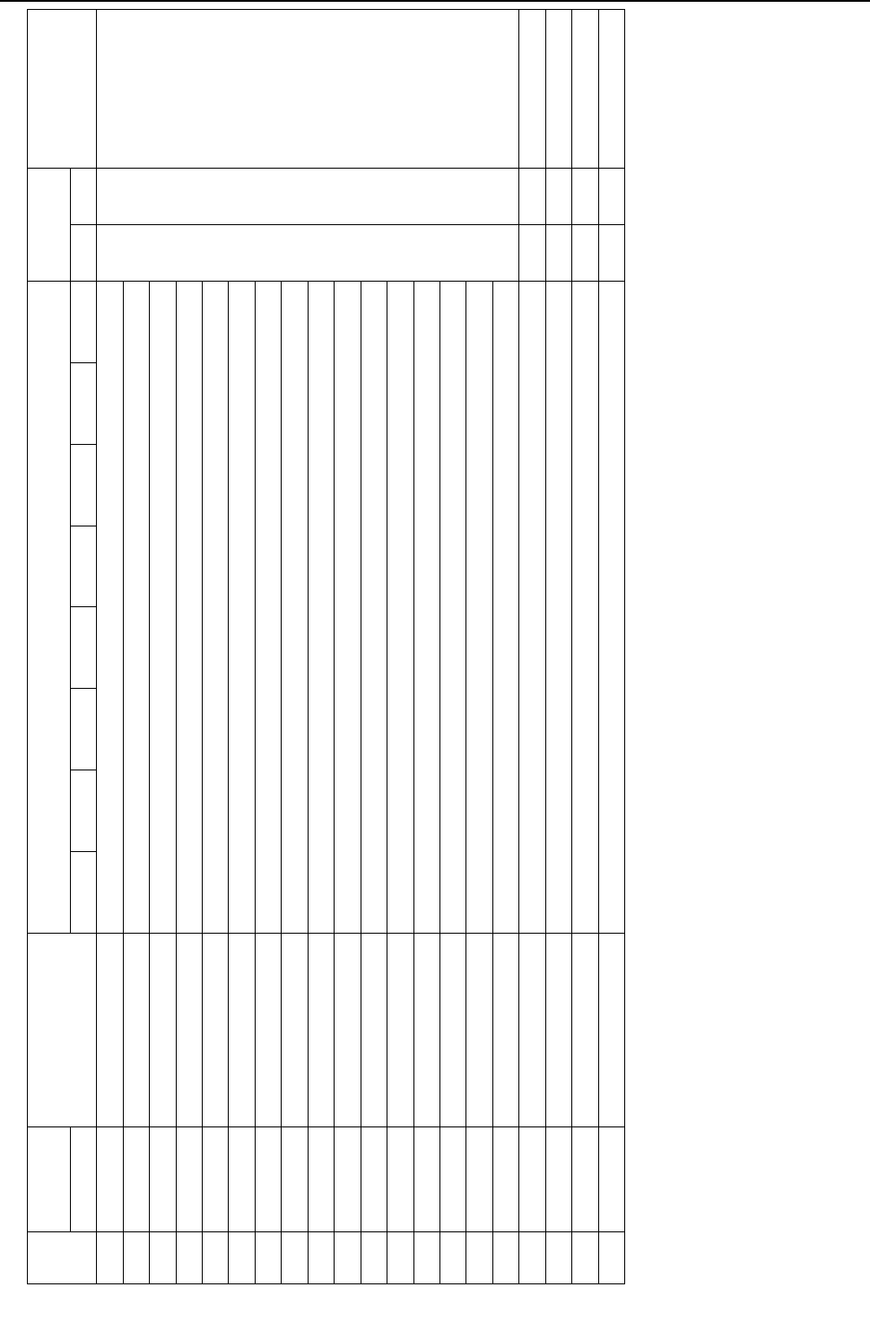
[ X LED Monitor Display on the Heat source Unit Board ]
- 385 -
HWE09080
492 0011011110 IC35 Liquid pipe temperature -99.9 to 999.9 B The unit is [°C]
493 1011011110 IC36 Liquid pipe temperature -99.9 to 999.9
494 0111011110 IC37 Liquid pipe temperature -99.9 to 999.9
495 1111011110 IC38 Liquid pipe temperature -99.9 to 999.9
496 0000111110 IC39 Liquid pipe temperature -99.9 to 999.9
497 1000111110 IC40 Liquid pipe temperature -99.9 to 999.9
498 0100111110 IC41 Liquid pipe temperature -99.9 to 999.9
499 1100111110 IC42 Liquid pipe temperature -99.9 to 999.9
500 0010111110 IC43 Liquid pipe temperature -99.9 to 999.9
501 1010111110 IC44 Liquid pipe temperature -99.9 to 999.9
502 0110111110 IC45 Liquid pipe temperature -99.9 to 999.9
503 1110111110 IC46 Liquid pipe temperature -99.9 to 999.9
504 0001111110 IC47 Liquid pipe temperature -99.9 to 999.9
505 1001111110 IC48 Liquid pipe temperature -99.9 to 999.9
506 0101111110 IC49 Liquid pipe temperature -99.9 to 999.9
507 1101111110 IC50 Liquid pipe temperature -99.9 to 999.9
508 0011111110
509 1011111110
510 0111111110
511 1111111110
Data on indoor unit system
No.
SW1
Item
Display Unit
(A, B) *1 Remarks
1234567890 LD1 LD2 LD3 LD4 LD5 LD6 LD7 LD8 OC OS
*1 A: The condition of either OC or OS is displayed individually. B: The condition of the entire refrigerant system is displayed.
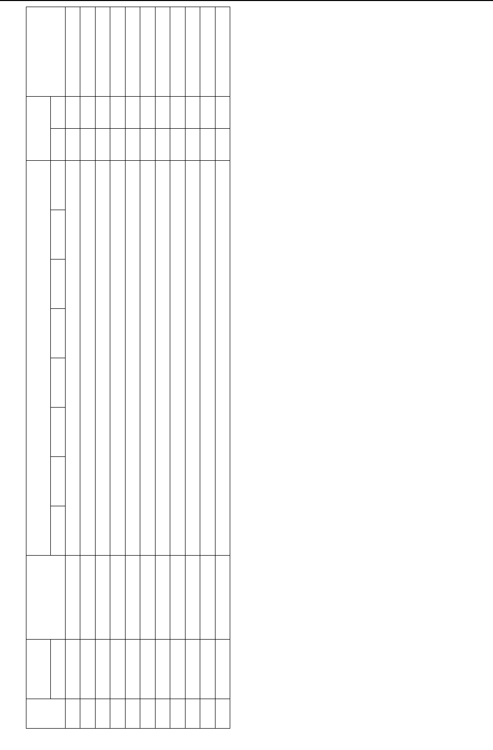
[ X LED Monitor Display on the Heat source Unit Board ]
- 386 -
HWE09080
Setting data
No.
SW1
Item
Display Unit
(A, B)*1 Remarks
1234567890 LD1 LD2 LD3 LD4 LD5 LD6 LD7 LD8 OC OS
512 0000000001 Self-address Alternate display of self address and unit model A A
513 1000000001 IC/FU address Count-up display of number of connected units B
514 0100000001 RC address Count-up display of number of connected units B
515 1100000001 BC/BS/TU address Count-up display of number of connected units B
516 0010000001 OS address Count-up display of number of connected units B
517 1010000001 Version/Capacity S/W version -> Refrigerant type -> Model and capacity -> Communication address A A
518 0110000001 OC address OC address display B
519 1110000001
520 0001000001
521 1001000001
522 0101000001
*1 A: The condition of either OC or OS is displayed individually. B: The condition of the entire refrigerant system is displayed.

[ X LED Monitor Display on the Heat source Unit Board ]
- 387 -
HWE09080
Data on indoor unit system
No.
SW1
Item
Display Unit
(A, B) *1 Remarks
1234567890 LD1 LD2 LD3 LD4 LD5 LD6 LD7 LD8 OC OS
523 1101000001 IC1 Gas pipe temperature -99.9 to 999.9 B The unit is [°C]
524 0011000001 IC2 Gas pipe temperature -99.9 to 999.9
525 1011000001 IC3 Gas pipe temperature -99.9 to 999.9
526 0111000001 IC4 Gas pipe temperature -99.9 to 999.9
527 1111000001 IC5 Gas pipe temperature -99.9 to 999.9
528 0000100001 IC6 Gas pipe temperature -99.9 to 999.9
529 1000100001 IC7 Gas pipe temperature -99.9 to 999.9
530 0100100001 IC8 Gas pipe temperature -99.9 to 999.9
531 1100100001 IC9 Gas pipe temperature -99.9 to 999.9
532 0010100001 IC10 Gas pipe temperature -99.9 to 999.9
533 1010100001 IC11 Gas pipe temperature -99.9 to 999.9
534 0110100001 IC12 Gas pipe temperature -99.9 to 999.9
535 1110100001 IC13 Gas pipe temperature -99.9 to 999.9
536 0001100001 IC14 Gas pipe temperature -99.9 to 999.9
537 1001100001 IC15 Gas pipe temperature -99.9 to 999.9
538 0101100001 IC16 Gas pipe temperature -99.9 to 999.9
539 1101100001 IC17 Gas pipe temperature -99.9 to 999.9
540 0011100001 IC18 Gas pipe temperature -99.9 to 999.9
541 1011100001 IC19 Gas pipe temperature -99.9 to 999.9
542 0111100001 IC20 Gas pipe temperature -99.9 to 999.9
543 1111100001 IC21 Gas pipe temperature -99.9 to 999.9
544 0000010001 IC22 Gas pipe temperature -99.9 to 999.9
545 1000010001 IC23 Gas pipe temperature -99.9 to 999.9
546 0100010001 IC24 Gas pipe temperature -99.9 to 999.9
547 1100010001 IC25 Gas pipe temperature -99.9 to 999.9
548 0010010001 IC26 Gas pipe temperature -99.9 to 999.9
549 1010010001 IC27 Gas pipe temperature -99.9 to 999.9
*1 A: The condition of either OC or OS is displayed individually. B: The condition of the entire refrigerant system is displayed.

[ X LED Monitor Display on the Heat source Unit Board ]
- 388 -
HWE09080
Data on indoor unit system
No.
SW1
Item
Display Unit
(A, B) *1 Remarks
1234567890 LD1 LD2 LD3 LD4 LD5 LD6 LD7 LD8 OC OS
550 0110010001 IC28 Gas pipe temperature -99.9 to 999.9 B The unit is [°C]
551 1110010001 IC29 Gas pipe temperature -99.9 to 999.9
552 0001010001 IC30 Gas pipe temperature -99.9 to 999.9
553 1001010001 IC31 Gas pipe temperature -99.9 to 999.9
554 0101010001 IC32 Gas pipe temperature -99.9 to 999.9
555 1101010001 IC33 Gas pipe temperature -99.9 to 999.9
556 0011010001 IC34 Gas pipe temperature -99.9 to 999.9
557 1011010001 IC35 Gas pipe temperature -99.9 to 999.9
558 0111010001 IC36 Gas pipe temperature -99.9 to 999.9
559 1111010001 IC37 Gas pipe temperature -99.9 to 999.9
560 0000110001 IC38 Gas pipe temperature -99.9 to 999.9
561 1000110001 IC39 Gas pipe temperature -99.9 to 999.9
562 0100110001 IC40 Gas pipe temperature -99.9 to 999.9
563 1100110001 IC41 Gas pipe temperature -99.9 to 999.9
564 0010110001 IC42 Gas pipe temperature -99.9 to 999.9
565 1010110001 IC43 Gas pipe temperature -99.9 to 999.9
566 0110110001 IC44 Gas pipe temperature -99.9 to 999.9
567 1110110001 IC45 Gas pipe temperature -99.9 to 999.9
568 0001110001 IC46 Gas pipe temperature -99.9 to 999.9
569 1001110001 IC47 Gas pipe temperature -99.9 to 999.9
570 0101110001 IC48 Gas pipe temperature -99.9 to 999.9
571 1101110001 IC49 Gas pipe temperature -99.9 to 999.9
572 0011110001 IC50 Gas pipe temperature -99.9 to 999.9
*1 A: The condition of either OC or OS is displayed individually. B: The condition of the entire refrigerant system is displayed.

[ X LED Monitor Display on the Heat source Unit Board ]
- 389 -
HWE09080
Data on indoor unit system
No.
SW1
Item
Display Unit
(A, B)*1 Remarks
1234567890 LD1 LD2 LD3 LD4 LD5 LD6 LD7 LD8 OC OS
573 1011110001 IC1SH -99.9 to 999.9 B The unit is [ °C ]
574 0111110001 IC2SH -99.9 to 999.9
575 1111110001 IC3SH -99.9 to 999.9
576 0000001001 IC4SH -99.9 to 999.9
577 1000001001 IC5SH -99.9 to 999.9
578 0100001001 IC6SH -99.9 to 999.9
579 1100001001 IC7SH -99.9 to 999.9
580 0010001001 IC8SH -99.9 to 999.9
581 1010001001 IC9SH -99.9 to 999.9
582 0110001001 IC10SH -99.9 to 999.9
583 1110001001 IC11SH -99.9 to 999.9
584 0001001001 IC12SH -99.9 to 999.9
585 1001001001 IC13SH -99.9 to 999.9
586 0101001001 IC14SH -99.9 to 999.9
587 1101001001 IC15SH -99.9 to 999.9
588 0011001001 IC16SH -99.9 to 999.9
589 1011001001 IC17SH -99.9 to 999.9
590 0111001001 IC18SH -99.9 to 999.9
591 1111001001 IC19SH -99.9 to 999.9
592 0000101001 IC20SH -99.9 to 999.9
593 1000101001 IC21SH -99.9 to 999.9
594 0100101001 IC22SH -99.9 to 999.9
595 1100101001 IC23SH -99.9 to 999.9
596 0010101001 IC24SH -99.9 to 999.9
597 1010101001 IC25SH -99.9 to 999.9
598 0110101001 IC26SH -99.9 to 999.9
599 1110101001 IC27SH -99.9 to 999.9
*1 A: The condition of either OC or OS is displayed individually. B: The condition of the entire refrigerant system is displayed.
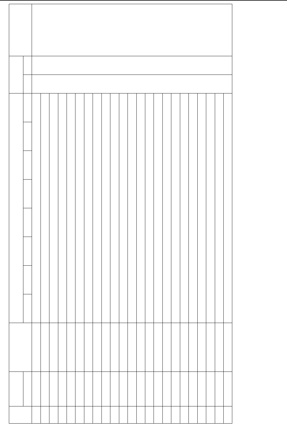
[ X LED Monitor Display on the Heat source Unit Board ]
- 390 -
HWE09080
600 0001101001 IC28SH -99.9 to 999.9 B The unit is [ °C ]
601 1001101001 IC29SH -99.9 to 999.9
602 0101101001 IC30SH -99.9 to 999.9
603 1101101001 IC31SH -99.9 to 999.9
604 0011101001 IC32SH -99.9 to 999.9
605 1011101001 IC33SH -99.9 to 999.9
606 0111101001 IC34SH -99.9 to 999.9
607 1111101001 IC35SH -99.9 to 999.9
608 0000011001 IC36SH -99.9 to 999.9
609 1000011001 IC37SH -99.9 to 999.9
610 0100011001 IC38SH -99.9 to 999.9
611 1100011001 IC39SH -99.9 to 999.9
612 0010011001 IC40SH -99.9 to 999.9
613 1010011001 IC41SH -99.9 to 999.9
614 0110011001 IC42SH -99.9 to 999.9
615 1110011001 IC43SH -99.9 to 999.9
616 0001011001 IC44SH -99.9 to 999.9
617 1001011001 IC45SH -99.9 to 999.9
618 0101011001 IC46SH -99.9 to 999.9
619 1101011001 IC47SH -99.9 to 999.9
620 0011011001 IC48SH -99.9 to 999.9
621 1011011001 IC49SH -99.9 to 999.9
622 0111011001 IC50SH -99.9 to 999.9
Data on indoor unit system
No.
SW1
Item
Display Unit
(A, B)*1 Remarks
1234567890 LD1 LD2 LD3 LD4 LD5 LD6 LD7 LD8 OC OS
*1 A: The condition of either OC or OS is displayed individually. B: The condition of the entire refrigerant system is displayed.

[ X LED Monitor Display on the Heat source Unit Board ]
- 391 -
HWE09080
Data on indoor unit system
No.
SW1
Item
Display Unit
(A, B)*1 Remarks
1234567890 LD1 LD2 LD3 LD4 LD5 LD6 LD7 LD8 OC OS
623 1111011001 IC1SC -99.9 to 999.9 B The unit is [ °C ]
624 0000111001 IC2SC -99.9 to 999.9
625 1000111001 IC3SC -99.9 to 999.9
626 0100111001 IC4SC -99.9 to 999.9
627 1100111001 IC5SC -99.9 to 999.9
628 0010111001 IC6SC -99.9 to 999.9
629 1010111001 IC7SC -99.9 to 999.9
630 0110111001 IC8SC -99.9 to 999.9
631 1110111001 IC9SC -99.9 to 999.9
632 0001111001 IC10SC -99.9 to 999.9
633 1001111001 IC11SC -99.9 to 999.9
634 0101111001 IC12SC -99.9 to 999.9
635 1101111001 IC13SC -99.9 to 999.9
636 0011111001 IC14SC -99.9 to 999.9
637 1011111001 IC15SC -99.9 to 999.9
638 0111111001 IC16SC -99.9 to 999.9
639 1111111001 IC17SC -99.9 to 999.9
640 0000000101 IC18SC -99.9 to 999.9
641 1000000101 IC19SC -99.9 to 999.9
642 0100000101 IC20SC -99.9 to 999.9
643 1100000101 IC21SC -99.9 to 999.9
644 0010000101 IC22SC -99.9 to 999.9
645 1010000101 IC23SC -99.9 to 999.9
646 0110000101 IC24SC -99.9 to 999.9
647 1110000101 IC25SC -99.9 to 999.9
648 0001000101 IC26SC -99.9 to 999.9
649 1001000101 IC27SC -99.9 to 999.9
*1 A: The condition of either OC or OS is displayed individually. B: The condition of the entire refrigerant system is displayed.
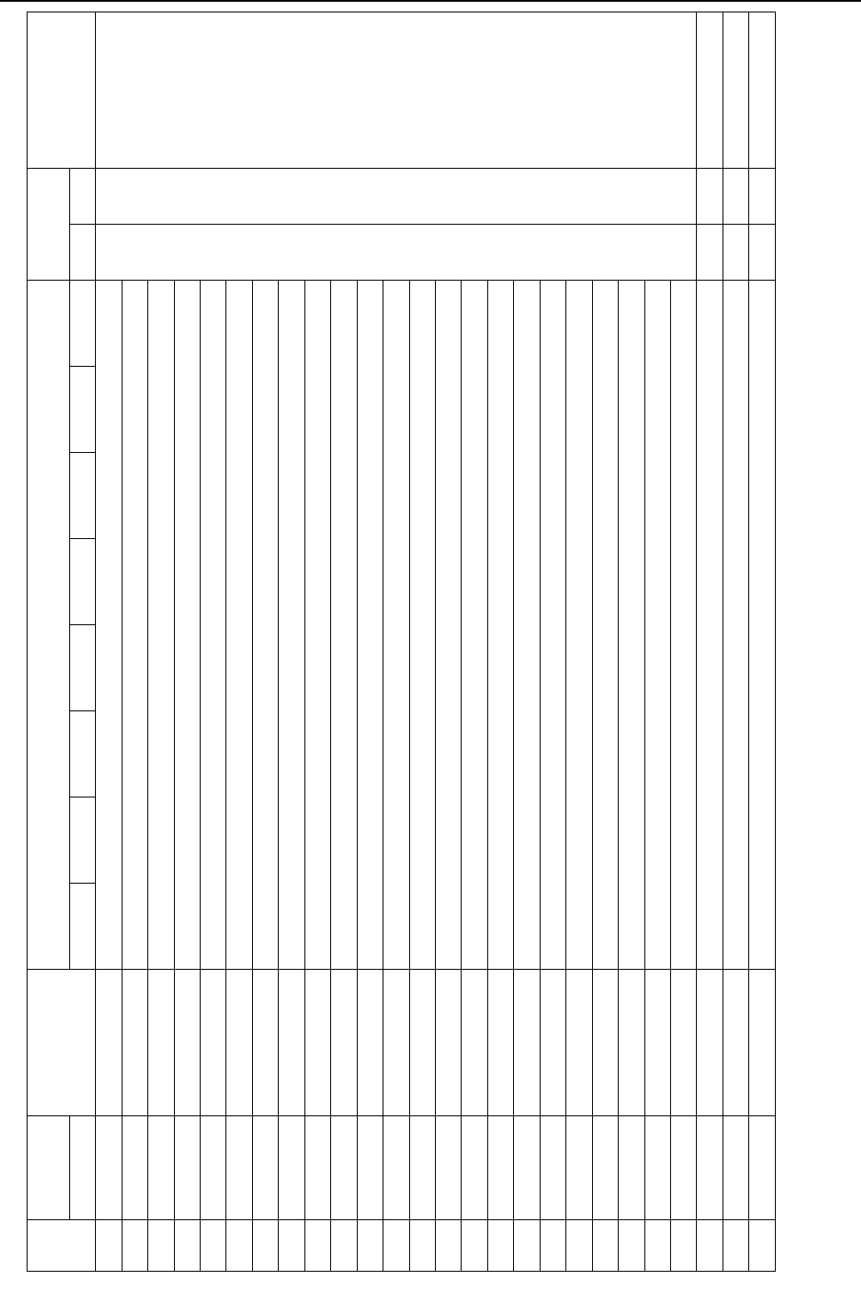
[ X LED Monitor Display on the Heat source Unit Board ]
- 392 -
HWE09080
650 0101000101 IC28SC -99.9 to 999.9 B The unit is [ °C ]
651 1101000101 IC29SC -99.9 to 999.9
652 0011000101 IC30SC -99.9 to 999.9
653 1011000101 IC31SC -99.9 to 999.9
654 0111000101 IC32SC -99.9 to 999.9
655 1111000101 IC33SC -99.9 to 999.9
656 0000100101 IC34SC -99.9 to 999.9
657 1000100101 IC35SC -99.9 to 999.9
658 0100100101 IC36SC -99.9 to 999.9
659 1100100101 IC37SC -99.9 to 999.9
660 0010100101 IC38SC -99.9 to 999.9
661 1010100101 IC39SC -99.9 to 999.9
662 0110100101 IC40SC -99.9 to 999.9
663 1110100101 IC41SC -99.9 to 999.9
664 0001100101 IC42SC -99.9 to 999.9
665 1001100101 IC43SC -99.9 to 999.9
666 0101100101 IC44SC -99.9 to 999.9
667 1101100101 IC45SC -99.9 to 999.9
668 0011100101 IC46SC -99.9 to 999.9
669 1011100101 IC47SC -99.9 to 999.9
670 0111100101 IC48SC -99.9 to 999.9
671 1111100101 IC49SC -99.9 to 999.9
672 0000010101 IC50SC -99.9 to 999.9
673 1000010101
674 0100010101
675 1100010101
Data on indoor unit system
No.
SW1
Item
Display Unit
(A, B)*1 Remarks
1234567890 LD1 LD2 LD3 LD4 LD5 LD6 LD7 LD8 OC OS
*1 A: The condition of either OC or OS is displayed individually. B: The condition of the entire refrigerant system is displayed.
[ X LED Monitor Display on the Heat source Unit Board ]
- 393 -
HWE09080
Setting data
No.
SW1
Item
Display Unit
(A, B)* 1 Remarks
1234567890 LD1 LD2 LD3 LD4 LD5 LD6 LD7 LD8 OC OS
676 0010010101 INV board S/W version 0.00 to 99.99 A A
677 1010010101
678 0110010101
679 1110010101
680 0001010101
681 1001010101
682 0101010101
683 1101010101
684 0011010101
685 1011010101
686 0111010101
687 1111010101
*1 A: The condition of either OC or OS is displayed individually. B: The condition of the entire refrigerant system is displayed.
[ X LED Monitor Display on the Heat source Unit Board ]
- 394 -
HWE09080
688 0000110101 Current time 00:00 to 23:59 A A Hour: minute
689 1000110101 Current time -2 00.00 to 99.12/1 to 31 Year and month, and date
alternate display
690 0100110101 Time of error detection 1 00:00 to 23:59 Hour: minute
691 1100110101 Time of error detection 1-2 00.00 to 99.12/1 to 31 Year and month, and date
alternate display
692 0010110101 Time of error detection 2 00:00 to 23:59 Hour: minute
693 1010110101 Time of error detection 2-2 00.00 to 99.12/1 to 31 Year and month, and date
alternate display
694 0110110101 Time of error detection 3 00:00 to 23:59 Hour: minute
695 1110110101 Time of error detection 3-2 00.00 to 99.12/1 to 31 Year and month, and date
alternate display
696 0001110101 Time of error detection 4 00:00 to 23:59 Hour: minute
697 1001110101 Time of error detection 4-2 00.00 to 99.12/1 to 31 Year and month, and date
alternate display
698 0101110101 Time of error detection 5 00:00 to 23:59 Hour: minute
699 1101110101 Time of error detection 5-2 00.00 to 99.12/1 to 31 Year and month, and date
alternate display
700 0011110101 Time of error detection 6 00:00 to 23:59 Hour: minute
701 1011110101 Time of error detection 6-2 00.00 to 99.12/1 to 31 Year and month, and date
alternate display
Setting data
No.
SW1
Item
Display Unit
(A, B)* 1 Remarks
1234567890 LD1 LD2 LD3 LD4 LD5 LD6 LD7 LD8 OC OS
*1 A: The condition of either OC or OS is displayed individually. B: The condition of the entire refrigerant system is displayed.
[ X LED Monitor Display on the Heat source Unit Board ]
- 395 -
HWE09080
702 0111110101 Time of error detection 7 00:00 to 23:59 A A Hour: minute
703 1111110101 Time of error detection 7-2 00.00 to 99.12/1 to 31 Year and month, and date
alternate display
704 0000001101 Time of error detection 8 00:00 to 23:59 Hour: minute
705 1000001101 Time of error detection 8-2 00.00 to 99.12/1 to 31 Year and month, and date
alternate display
706 0100001101 Time of error detection 9 00:00 to 23:59 Hour: minute
707 1100001101 Time of error detection 9-2 00.00 to 99.12/1 to 31 Year and month, and date
alternate display
708 0010001101 Time of error detection 10 00:00 to 23:59 Hour: minute
709 1010001101 Time of error detection 10-2 00.00 to 99.12/1 to 31 Year and month, and date
alternate display
710 0110001101 Time of last data backup be-
fore error 00:00 to 23:59 Hour: minute
711 1110001101 Time of last data backup be-
fore error -2 00.00 to 99.12/1 to 31 Year and month, and date
alternate display
712 0001001101
713 1001001101
Setting data
No.
SW1
Item
Display Unit
(A, B)* 1 Remarks
1234567890 LD1 LD2 LD3 LD4 LD5 LD6 LD7 LD8 OC OS
*1 A: The condition of either OC or OS is displayed individually. B: The condition of the entire refrigerant system is displayed.

[ X LED Monitor Display on the Heat source Unit Board ]
- 396 -
HWE09080
Data on indoor unit system
No.
SW1
Item
Display Unit
(A, B)* 1 Remarks
1234567890 LD1 LD2 LD3 LD4 LD5 LD6 LD7 LD8 OC OS
714 0101001101 IC1 LEV opening 0000 to 9999 B Fully open: 2000
715 1101001101 IC2 LEV opening 0000 to 9999
716 0011001101 IC3 LEV opening 0000 to 9999
717 1011001101 IC4 LEV opening 0000 to 9999
718 0111001101 IC5 LEV opening 0000 to 9999
719 1111001101 IC6 LEV opening 0000 to 9999
720 0000101101 IC7 LEV opening 0000 to 9999
721 1000101101 IC8 LEV opening 0000 to 9999
722 0100101101 IC9 LEV opening 0000 to 9999
723 1100101101 IC10 LEV opening 0000 to 9999
724 0010101101 IC11 LEV opening 0000 to 9999
725 1010101101 IC12 LEV opening 0000 to 9999
726 0110101101 IC13 LEV opening 0000 to 9999
727 1110101101 IC14 LEV opening 0000 to 9999
728 0001101101 IC15 LEV opening 0000 to 9999
729 1001101101 IC16 LEV opening 0000 to 9999
730 0101101101 IC17 LEV opening 0000 to 9999
731 1101101101 IC18 LEV opening 0000 to 9999
732 0011101101 IC19 LEV opening 0000 to 9999
733 1011101101 IC20 LEV opening 0000 to 9999
734 0111101101 IC21 LEV opening 0000 to 9999
735 1111101101 IC22 LEV opening 0000 to 9999
736 0000011101 IC23 LEV opening 0000 to 9999
737 1000011101 IC24 LEV opening 0000 to 9999
738 0100011101 IC25 LEV opening 0000 to 9999
739 1100011101 IC26 LEV opening 0000 to 9999
740 0010011101 IC27 LEV opening 0000 to 9999
*1 A: The condition of either OC or OS is displayed individually. B: The condition of the entire refrigerant system is displayed.

[ X LED Monitor Display on the Heat source Unit Board ]
- 397 -
HWE09080
741 1010011101 IC28 LEV opening 0000 to 9999 B Fully open: 2000
742 0110011101 IC29 LEV opening 0000 to 9999
743 1110011101 IC30 LEV opening 0000 to 9999
744 0001011101 IC31 LEV opening 0000 to 9999
745 1001011101 IC32 LEV opening 0000 to 9999
746 0101011101 IC33 LEV opening 0000 to 9999
747 1101011101 IC34 LEV opening 0000 to 9999
748 0011011101 IC35 LEV opening 0000 to 9999
749 1011011101 IC36 LEV opening 0000 to 9999
750 0111011101 IC37 LEV opening 0000 to 9999
751 1111011101 IC38 LEV opening 0000 to 9999
752 0000111101 IC39 LEV opening 0000 to 9999
753 1000111101 IC40 LEV opening 0000 to 9999
754 0100111101 IC41 LEV opening 0000 to 9999
755 1100111101 IC42 LEV opening 0000 to 9999
756 0010111101 IC43 LEV opening 0000 to 9999
757 1010111101 IC44 LEV opening 0000 to 9999
758 0110111101 IC45 LEV opening 0000 to 9999
759 1110111101 IC46 LEV opening 0000 to 9999
760 0001111101 IC47 LEV opening 0000 to 9999
761 1001111101 IC48 LEV opening 0000 to 9999
762 0101111101 IC49 LEV opening 0000 to 9999
763 1101111101 IC50 LEV opening 0000 to 9999
Data on indoor unit system
No.
SW1
Item
Display Unit
(A, B)* 1 Remarks
1234567890 LD1 LD2 LD3 LD4 LD5 LD6 LD7 LD8 OC OS
*1 A: The condition of either OC or OS is displayed individually. B: The condition of the entire refrigerant system is displayed.
[ X LED Monitor Display on the Heat source Unit Board ]
- 398 -
HWE09080
764 0011111101 IC1 Operation mode
0000 : Stop 0001 : Ventilation 0002 : Cooling 0003 : Heating 0004 : Dry
B When WR2 is used, the
four LDs on the left (LD1-
4) display operation
mode, and the four LDs
on the right (LD5-LD8)
display port address.
(Displayed alternately ev-
ery five seconds)
765 1011111101 IC2 Operation mode
766 0111111101 IC3Operation mode
767 1111111101 IC4 Operation mode
768 0000000011 IC5 Operation mode
Data on indoor unit system
No.
SW1
Item
Display Unit
(A, B)* 1 Remarks
1234567890 LD1 LD2 LD3 LD4 LD5 LD6 LD7 LD8 OC OS
*1 A: The condition of either OC or OS is displayed individually. B: The condition of the entire refrigerant system is displayed.
[ X LED Monitor Display on the Heat source Unit Board ]
- 399 -
HWE09080
769 1000000011 IC6 Operation mode
0000 : Stop 0001 : Ventilation 0002 : Cooling 0003 : Heating 0004 : Dry
BWhen WR2 is used, the
four LDs on the left
(LD1-4) display opera-
tion mode, and the four
LDs on the right (LD5-
LD8) display port ad-
dress.
(Displayed alternately
every five seconds)
770 0100000011 IC7 Operation mode
771 1100000011 IC8 Operation mode
772 0010000011 IC9 Operation mode
773 1010000011 IC10 Operation mode
774 0110000011 IC11 Operation mode
775 1110000011 IC12 Operation mode
776 0001000011 IC13 Operation mode
777 1001000011 IC14 Operation mode
778 0101000011 IC15 Operation mode
779 1101000011 IC16 Operation mode
780 0011000011 IC17 Operation mode
781 1011000011 IC18 Operation mode
782 0111000011 IC19 Operation mode
783 1111000011 IC20 Operation mode
784 0000100011 IC21 Operation mode
785 1000100011 IC22 Operation mode
786 0100100011 IC23 Operation mode
787 1100100011 IC24 Operation mode
788 0010100011 IC25 Operation mode
789 1010100011 IC26 Operation mode
790 0110100011 IC27 Operation mode
791 1110100011 IC28 Operation mode
792 0001100011 IC29 Operation mode
793 1001100011 IC30 Operation mode
794 0101100011 IC31 Operation mode
795 1101100011 IC32 Operation mode
796 0011100011 IC33 Operation mode
Data on indoor unit system
No.
SW1
Item
Display Unit
(A, B)* 1 Remarks
1234567890 LD1 LD2 LD3 LD4 LD5 LD6 LD7 LD8 OC OS
*1 A: The condition of either OC or OS is displayed individually. B: The condition of the entire refrigerant system is displayed.
[ X LED Monitor Display on the Heat source Unit Board ]
- 400 -
HWE09080
797 1011100011 IC34 Operation mode
0000 : Stop 0001 : Ventilation 0002 : Cooling 0003 : Heating 0004 : Dry
BWhen WR2 is used, the
four LDs on the left
(LD1-4) display opera-
tion mode, and the four
LDs on the right (LD5-
LD8) display port ad-
dress.
(Displayed alternately
every five seconds)
798 0111100011 IC35 Operation mode
799 1111100011 IC36 Operation mode
800 0000010011 IC37 Operation mode
801 1000010011 IC38 Operation mode
802 0100010011 IC39 Operation mode
803 1100010011 IC40 Operation mode
804 0010010011 IC41 Operation mode
805 1010010011 IC42 Operation mode
806 0110010011 IC43 Operation mode
807 1110010011 IC44 Operation mode
808 0001010011 IC45 Operation mode
809 1001010011 IC46 Operation mode
810 0101010011 IC47 Operation mode
811 1101010011 IC48 Operation mode
812 0011010011 IC49 Operation mode
813 1011010011 IC50 Operation mode
814 0111010011 IC1 filter 0000 to 9999 B Hours since last mainte-
nance [ h ]
815 1111010011 IC2 filter 0000 to 9999
816 0000110011 IC3 filter 0000 to 9999
817 1000110011 IC4 filter 0000 to 9999
818 0100110011 IC5 filter 0000 to 9999
819 1100110011 IC6 filter 0000 to 9999
820 0010110011 IC7 filter 0000 to 9999
821 1010110011 IC8 filter 0000 to 9999
822 0110110011 IC9 filter 0000 to 9999
823 1110110011 IC10 filter 0000 to 9999
824 0001110011 IC11 filter 0000 to 9999
Data on indoor unit system
No.
SW1
Item
Display Unit
(A, B)* 1 Remarks
1234567890 LD1 LD2 LD3 LD4 LD5 LD6 LD7 LD8 OC OS
*1 A: The condition of either OC or OS is displayed individually. B: The condition of the entire refrigerant system is displayed.

[ X LED Monitor Display on the Heat source Unit Board ]
- 401 -
HWE09080
825 1001110011 IC12 filter 0000 to 9999 B Hours since last mainte-
nance [ h ]
826 0101110011 IC13 filter 0000 to 9999
827 1101110011 IC14 filter 0000 to 9999
828 0011110011 IC15 filter 0000 to 9999
829 1011110011 IC16 filter 0000 to 9999
830 0111110011 IC17 filter 0000 to 9999
831 1111110011 IC18 filter 0000 to 9999
832 0000001011 IC19 filter 0000 to 9999
833 1000001011 IC20 filter 0000 to 9999
834 0100001011 IC21 filter 0000 to 9999
835 1100001011 IC22 filter 0000 to 9999
836 0010001011 IC23 filter 0000 to 9999
837 1010001011 IC24 filter 0000 to 9999
838 0110001011 IC25 filter 0000 to 9999
839 1110001011 IC26 filter 0000 to 9999
840 0001001011 IC27 filter 0000 to 9999
841 1001001011 IC28 filter 0000 to 9999
842 0101001011 IC29 filter 0000 to 9999
843 1101001011 IC30 filter 0000 to 9999
844 0011001011 IC31 filter 0000 to 9999
845 1011001011 IC32 filter 0000 to 9999
846 0111001001 IC33 filter 0000 to 9999
847 1111001011 IC34 filter 0000 to 9999
848 0000101011 IC35 filter 0000 to 9999
849 1000101011 IC36 filter 0000 to 9999
850 0100101011 IC37 filter 0000 to 9999
851 1100101011 IC38 filter 0000 to 9999
852 0010101011 IC39 filter 0000 to 9999
Data on indoor unit system
No.
SW1
Item
Display Unit
(A, B)* 1 Remarks
1234567890 LD1 LD2 LD3 LD4 LD5 LD6 LD7 LD8 OC OS
*1 A: The condition of either OC or OS is displayed individually. B: The condition of the entire refrigerant system is displayed.
[ X LED Monitor Display on the Heat source Unit Board ]
- 402 -
HWE09080
853 1010101011 IC40 filter 0000 to 9999 B Hours since last mainte-
nance [ h ]
854 0110101011 IC41 filter 0000 to 9999
855 1110101011 IC42 filter 0000 to 9999
856 0001101011 IC43 filter 0000 to 9999
857 1001101011 IC44 filter 0000 to 9999
858 0101101011 IC45 filter 0000 to 9999
859 1101101011 IC46 filter 0000 to 9999
860 0011101011 IC47 filter 0000 to 9999
861 1011101011 IC48 filter 0000 to 9999
862 0111101011 IC49 filter 0000 to 9999
863 1111101011 IC50 filter 0000 to 9999
Data on indoor unit system
No.
SW1
Item
Display Unit
(A, B)* 1 Remarks
1234567890 LD1 LD2 LD3 LD4 LD5 LD6 LD7 LD8 OC OS
*1 A: The condition of either OC or OS is displayed individually. B: The condition of the entire refrigerant system is displayed.

[ X LED Monitor Display on the Heat source Unit Board ]
- 403 -
HWE09080
Other types of data
No.
SW1
Item
Display Unit
(A, B) *1 Remarks
1234567890 LD1 LD2 LD3 LD4 LD5 LD6 LD7 LD8 OC OS
864 0000011011
865 1000011011
866 0100011011
867 1100011011
868 0010011011
869 1010011011
870 0110011011
871 1110011011 U-phase current effec-
tive value 1 -99.9 to 999.9 A A The unit is [ A ]
872 0001011011 W-phase current effec-
tive value 1 -99.9 to 999.9 A A
873 1001011011 Power factor phase an-
gle 1 -99.9 to 999.9 A A The unit is [ deg ]
874 0101011011
875 1101011011
876 0011011011
877 1011011011
878 0111011011
879 1111011011
880 0000111011 Control board
Reset counter 0 to 254 A A The unit is [ time ]
881 1000111011 INV board
Reset counter 0 to 254 A A
882 0100111011
883 1100111011
884 0010111011
885 1010111011
886 0110111011
887 1110111011
*1 A: The condition of either OC or OS is displayed individually. B: The condition of the entire refrigerant system is displayed.

[ X LED Monitor Display on the Heat source Unit Board ]
- 404 -
HWE09080
888 0001111011
889 1001111011
890 0101111011
891 1101111011
892 0011111011
893 1011111011
894 0111111011
895 1111111011
896 0000000111
897 1000000111
898 0100000111
899 1100000111
900 0010000111
901 1010000111
902 0110000111
903 1110000111
904 0001000111
905 1001000111
906 0101000111
907 1101000111
1020 0011111111
1021 1011111111
1022 0111111111
1023 1111111111
Other types of data
No.
SW1
Item
Display Unit
(A, B) *1 Remarks
1234567890 LD1 LD2 LD3 LD4 LD5 LD6 LD7 LD8 OC OS
*1 A: The condition of either OC or OS is displayed individually. B: The condition of the entire refrigerant system is displayed.