Hallmark DKL1608 2.4G module User Manual DKL1608 S
Hallmark Cards, Inc. 2.4G module DKL1608 S
Hallmark >
Contents
- 1. User Manual Statement.pdf
- 2. User Manual.pdf
User Manual.pdf
1
DKL1608-S User Manual
FCC ID: SQ9DKL1608 IC: 5768A-DKL1608
1 CONTROL STATES
1.1 POWER-ON RESET
When power is applied to VDD and is over 1.9V threshold, DKL1608-S will run power-on reset.
Once power-on reset is completed, the device will be in power-down mode.
1.2 POWER-DOWN MODE
In power-down mode, DKL1608-S is in deep-sleep and only the SPI interface is active. DKL1608-S
is in power-down mode when PWR_ON is set to 0.
The device enters power-down mode whenever PWR_ON is set to zero.
1.3 STANDBY MODE
Setting PWR_ON bit to “1” will activate device to standby mode (while CE remains 0). In standby
mode, the crystal oscillator is active, and the device is ready to quickly enter TX or RX mode.
1.4 TX MODE
DKL1608-S transmits packets in TX mode. To operate in TX mode, the device needs to be set up as
a PTX (RX_ON=0), standby mode (PWR_ON=1), and a payload(s) in FIFO. There are two modes of
TX: pulsed (single packet mode) and continuous mode. A CE high pulse of at least 10 us triggers a
single packet to be sent. Keeping CE high will set the device to continuous TX mode, which will
send out all packets in FIFO. After FIFO is emptied, the device will power-off radio and digital
baseband to save current, but the device will commence transmission as soon as a new payload
enters FIFO.
When auto-ACK feature is enabled, a PRX device automatically enters TX mode to send back an
ACK packet after a valid packet is received from a PTX.
1.5 RX MODE
DKL1608-S receives packets in RX mode. The device needs to be set up as a PRX (RX_ON=1) and
in standby mode (PWR_ON=1). Pulling CE pin high sets the device to RX mode and will continue
listening for packets as long as CE is held high. Payloads of valid packets will be placed into the RX
FIFO.
When auto-ACK feature is enabled, a PTX device automatically enters RX mode after transmission
to listen for an ACK packet from the PRX.
1.6 RADIO SETUP
DKL1608-S supports 250kbps, 1Mbps, and 2 Mbps air bit rate. The choice of which bit rate to use
depends on range, current consumption, and data rate needed. Lower bit rate has longer range,
while higher bit rate has lower current consumption and reduced probability of in-air collision.
Air rate is set by the SETUP_RF register.
The channel may be set in 1 MHz increment from 2400 MHz to 2483 MHz. Although it is possible
2
to set the channel frequency higher than 2483 MHz, it is not recommended for this may violate
regional regulations. For 250kbps and 1Mbps operation, the channel may be set in 1 MHz
increment; for 2Mbps operation, the channel spacing should be 2 MHz or more. Channel
selection is set by the RF_CH register.
In addition to the device address, the bit rate and channel frequency need to be set the same for
the radios to communicate with each other.
1.7 RSSI RECORDER
DKL1608-S features an advanced RSSI block and control, allowing the receiver host to collect
detailed information of the current RX channel. There are two decision thresholds that can be
individually set. An RSSI recorder generates a log of the channel traffic. With two decision
thresholds, the host can separate the receiving signal into three ranges: low, medium, and high.
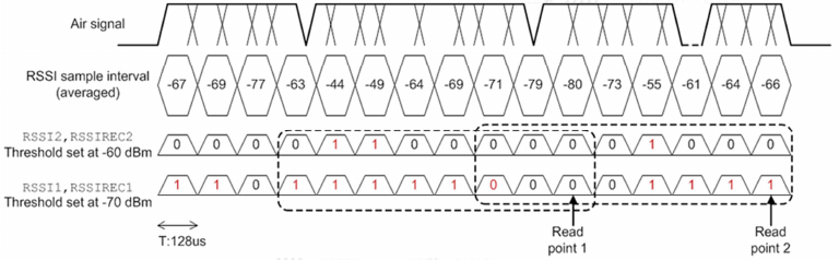
The RSSI recorder consists of two 8-bit shift registers corresponding to the two thresholds, and it
keeps track of the RSSI readings for the past 8 time slots. A single time slot is 128 us. The most
recent RSSI record is placed at the MSB of the shift register, and the bits are shifted toward LSB as
time progresses. This recording RSSI scheme can be useful in detecting complex channel
behaviors such as fading, interference, and may assist MCU in channel selection.
The RSSI enable setting and RSSI readout are in the RSSI register setting. The RSSI threshold and
recorder are in address 0x18. Figure 6 shows the basic concept of the RSSI recorder scheme. At
read point 1, [RSSI1, RSSI2] readout will be [0, 0], RSSIREC1 readout will be 0x1F and RSSIREC2
readout will be 0x06; at read point 2, [RSSI1, RSSI2] will read [0, 1], RSSIREC1 will read 0xF0 and
RSSIREC2 will read 0x10.
DKL1608-S also has a unique identifier encoded in [RSSIREC2, RSSIREC1] and can be read right
after POR. The 16-bit unique ID for DKL1608-S is 0x7241.
To save current, the RSSI is set to be off by default. To turn on the RSSI, enable bit 4 of the RSSI
register. The two decision thresholds are also indicated at bit 0 and bit 1 of the RSSI register.
RSSI recorder scheme
3
2 PACKET INFORMATION
2.1 PACKET FORMAT
Packet Format
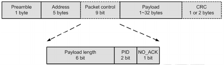
The packet consists of 5 portions: preamble, address, packet control, payload, and CRC. The
preamble, address, and payload are required fields; packet control and CRC are optional fields,
depending on settings.
2.2 PREAMBLE
The preamble is a one-byte alternating sequence of 01010101 or 10101010, depending on the
first bit in the address. If the first address bit is 1 the preamble will be set to 10101010; if the first
address bit is 0, the preamble is set to 01010101.
2.3 ADDRESS
This field holds the address of the receiver.
Addresses with only one or two transitions (e.g. 0x000005FFFF or 0x00FF000000) or as a
continuation of the preamble (010101.) are not recommended for they may increase the packet
error rate.
2.4 PACKET CONTROL
The packet control field consists of 9 bits, containing a 6-bit payload length field, a 2-bit packet
identity (PID) field, and a one-bit NO_ACK flag.
The payload length is used when dynamic payload length feature is enabled. It specifies payload
length in bytes, which can range from 1 to 32. Values higher than 32 are ignored.
The PID field is used to detect whether the packet is new or retransmitted. This field prevents the
PRX from delivering the same payload more than once to the RX host MCU. The PID is
incremented at the TX side for each new packet received through the SPI. The PID and CRC fields
are used together by the PRX to determine whether the received packet is retransmitted or new.
The NO_ACK flag is used when the auto-ACK feature is enabled. Setting the flag high tells the
receiver that this packet does not need to be auto acknowledged. This flag is set on the PTX by
using the command W_TX_PLOAD_NOACK, instead of W_TX_PLOAD, to write the TX payload. To
use this function requires enabling the EN_DYN_ACK bit in the FEATURE register. When this
option is used to transmit, the PTX goes directly to standby mode after transmitting the packet,
and the PRX will not transmit an ACK packet after the packet is received.
4
2.5 PAYLOAD
The payload can be 1 to 32 bytes wide. The payload can be set either static or dynamic in length,
defined by the packet control field. The default setup is static payload length. The static payload
length is set by the RX_PW_Px register on the receiver side. Payload length on the transmitter
side is set by the number of bytes placed in the TX_FIFO and must be equal to the value set in the
RX_PW_Px register on the receiver side.
Dynamic payload length enables the transmitter to send packets of variable length to the receiver.
The receiver can decode the payload length automatically from the control field value. The MCU
can read the received payload length by using R_RX_PL_WID command.
To enable dynamic payload, set the EN_DPL bit in the FEATURE register to 1. In RX mode, the
DYNPD register must be set. A PTX that transmits to a PRX with dynamic payload enabled must
have the DPL_P0 bit in DYNPD set.
2.6 CYCLIC REDUNDANCY CHECK (CRC)
The CRC is an error detection mechanism in the packet. It can be set to 1 or 2 bytes and is
calculated over the address, packet control field, and payload.
The polynomial for 1-byte CRC is X
8
+ X
2
+ X + 1, with an initial value of 0xFF.
The polynomial for 2-byte CRC is X
8
+ X
2
+ X + 1, with an initial value of 0xFFFF.
The CRCC bit in the CFG_TOP register sets the CRC length, and EN_CRC controls whether CRC is
used. The CRC is a mandatory field for packets with auto-ACK or dynamic payload length enabled,
and will override the EN_CRC bit setting. If CRC is enabled, packets will be dropped if CRC fails.
2.7 PACKET HANDLING
In TX mode, the PHY engine fetches a payload from TX FIFO, assembles the payload into a packet
and transmits the packet in a short burst. After transmission, if the PTX packet has the NO_ACK
flag set, the device sets TX_DS to 1 and gives an active low interrupt IRQ to MCU. If the PTX
packet is an auto-ACK one, the PTX needs to receive an ACK from the PRX and then asserts the
TX_DS IRQ.
The receiver continuously listens to the air channel for radio signal, and once it is synchronized to
a likely signal, the PHY engine will validate the address and CRC of the possible packet. If a valid
packet is detected and is a new one, the PHY engine writes the payload to RX FIFO, sets RX_DR to
1 and gives an active low interrupt IRQ to MCU.
When auto-acknowledge is enabled (EN_AA=1), the PTX will enter RX mode after transmission to
wait for an ACK packet. If an ACK is not received within delay set by ARD[3:0], the PTX
re-transmits the original packet and enters RX mode to wait for ACK. The above action is
repeated until an ACK packet is received or the number of re- transmission exceeds a threshold
set by ARC[3:0]. If the latter threshold is met, the PTX will set MAX_RT to 1 and give an active low
interrupt IRQ to MCU. Two packet loss counters (ARC_CNT and PLOS_CNT) are incremented each
time a packet is lost. The ARC_CNT counts the number of retransmissions for the current
transaction. The PLOS_CNT counts the total number of retransmissions since the last channel
change. Initiating a new transmission resets the ARC_CNT. Writing to the RF_CH register resets
the PLOS_CNT. The ARC_CNT and the PLOS_CNT are in the OBSERVE_TX register. They may be
5
used as an indicator of overall channel quality.
The PTX device will retransmit if its RX FIFO is full but receives an ACK packet with payload. As an
alternative for the PTX to auto retransmit, it is possible to manually set the device to retransmit a
packet a number of times. This is done by the REUSE_TX_PL command.
When auto-ACK is enabled, it is possible for the PRX to send a payload along with the ACK packet.
To use this feature, the EN_ACK_PAY bit in the FEATURE register needs to be set. In addition, the
dynamic payload function also needs to be set. The MCU at the PRX needs to upload the payload
to the PRX’s TX FIFO by using the W_ACK_PAYLOAD command. Payloads pending in the TX FIFO
(of the PRX) will be sent after a new packet is received from PTX. Up to three payloads may be
pending in the TX FIFO (of the PRX) at the same time.
3 DATA AND CONTROL INTERFACE
3.1 TX AND RX FIFO
DKL1608-S has three levels of FIFO for the transmitter, and three levels of FIFO for receiver. Each
FIFO level is 32 bytes in length. The TX FIFO is used to store payloads that are to be transmitted,
and the RX FIFO is used to store the received payloads that have not been downloaded by the
host MCU. Up to three payloads may be stored in a TX FIFO, and up to three payloads may be
stored in an RX FIFO. The RX FIFO will also record which data pipe the payload comes from. Data
pipe information is in the STATUS register and is read out from SDO during every SPI command.
Successful transmission of a payload will clear a slot in the TX FIFO, and a reading from RX FIFO
will clear an RX payload slot. Both FIFOs are accessed through the SPI using dedicated commands.
Data access to the two FIFOs, as the name suggests, follows the first-in first-out principle.
In a PRX device, the TX FIFO can store payloads of ACK packets for up to three different PTX
devices. The TX FIFO in a PRX may be filled up and blocked if all pending payloads are addressed
to the pipe where the link to the PTX is lost. In this case, the MCU should flush the TX FIFO by
using the FLUSH_TX command.
The TX FIFO may be accessed using three different commands: W_TX_PLOAD, W_ACK_PLOAD,
and W_TX_PLOAD_NOACK. All three commands access the same TX FIFO. The description of the
commands is detailed in the SPI Command section. The RX FIFO is accessed by the command
R_RX_PLOAD, and it may be accessed in both PTX and PRX mode. The payload width of the top
slot in RX FIFO is read by the command R_RX_PL_WID.
The statuses of the TX FIFO and RX FIFO are in the STATUS_FIFO register. The device may also be
configured to read out the STATUS_FIFO register during every command by adjusting the
STAT_SETUP setting in FEATURE register.
The device may retransmit its last transmitted payload by the command REUSE_TX_PL and
pulsing the CE pin to trigger transmission. Payload reuse will remain active until W_TX_PLOAD or
FLUSH_TX command is executed.
3.2 INTERRUPT
DKL1608-S’s pin 6 is an active-low interrupt pin, used to inform host MCU of various events.
6
Interrupt is activated when the TX_DS, RX_DR, or MAX_RT in the STATUS register is set high. The
IRQ pin is reset when the host writes “1” to the IRQ source bit in the STATUS register. In the
CONFIG register, there are three mask bits, which may be used to set which event triggers the
IRQ pin. By default all IRQ sources are enabled.
Please note that the 3-bit pipe information in the STATUS register is updated during the IRQ pin
transition. The pipe information is unreliable if the STATUS register is read during the IRQ pin
high-to-low transition.
3.3 STAR CONNECTION
DKL1608-S may be configured as a PRX receiving from up to 6 PTX devices, forming a star
network. Once configured, the connections are presented as different data pipes to the PRX host.
The following settings are common to all data pipes:
• CRC on/off (always enabled when using auto-ACK or dynamic payload)
• CRC setting (1 or 2 bytes)
• RX address width
• Frequency channel
• Air data rate
Data pipes are enabled with the EN_RXADDR register. By default data pipe 0 and 1 are enabled.
Data pipe addresses are configured in the RX_ADDR_PX register, where “X” is from
0 to 5. Each data pipe should have a unique address. Data pipe 0 has a unique address.
Addresses of data pipes 1 to 5 differ only by the LSByte.
During a star connection, since the PRX device will be transmitting ACK packets to different PTX
devices, to identify the correct destination, the PRX device uses the RX address of the particular
pipe as the packet address when sending ACK packets. Therefore for the PTX devices, their RX
address needs to be set the same as their TX address. Furthermore, since all data pipes operate
at the same channel frequency, only one data pipe should be active at any time. When multiple
PTXs are transmitting to a PRX, the ARD may be set at different values so that collisions happen
only once.
3.4 SPI COMMAND
DKL1608-S is controlled by a standard SPI interface. All commands must be initiated by a high to
low transition on pin CSN.
The status of the chip is shifted out on the SDO pin simultaneously as the SPI command word is
serially fed into the SDI pin. Typically the status output is the STATUS register bits, but it can be
configured to report RX status or FIFO status. The output of the SDO pin is set by the STAT_SETUP
in the FEATURE register.
The SPI command format consists of an 8-bit command word (from MSB to LSB) followed by the
data in bytes. Data bytes are fed from LSByte to MSByte, and start with the MSBit in each byte
first.
The R_REG and W_REG commands operate on single or multi-byte registers. When accessing
multi-byte registers, writing of bytes may be terminated before all bytes are written, leaving

7
unwritten MSByte(s) unchanged.
Note: The 3 bit pipe information in the STATUS register is updated when IRQ pin changes from
high to low. Therefore, the pipe information is unreliable if the STATUS register is read during an
IRQ transition.
Table 1: SPI Commands
Command
na
m
e Co
mm
and
w
o
r
d
(
b
i
na
r
y)
Nu
m
be
r
of data
b
yt
es
Desc
ri
pt
i
on
R
_
R
E
G
000X XXXX 1 to 5 Read registers. XXXXX is the 5
-
b
i
t
register add
r
ess
W
_
R
E
G
001Y YYYY 1 to 5 Write to registers. YYYYY is the 5
-
bit register address. Executable
i
n
power-down or standby mode
on
l
y
R
_
R
X
_
P
L
O
A
D
0
110
00
0
1
1
to
32
Re
a
d
R
X
p
a
y
l
o
ad.
Read
o
pe
r
a
tion
always starts at byte 0. Payload
i
s
deleted from FIFO after it is
r
ead.
Us
e
d
i
n
R
X
m
o
de.
W
_
T
X
_
P
L
O
A
D
1010 0000 1 to 32 Write TX payload. Write
ope
r
at
i
on always starts at byte
F
L
U
S
H
_
T
X
1
110
00
0
1
0
F
l
u
sh
TX
F
I
F
O
,
us
e
d
i
n
T
X
m
o
d
e
F
L
U
S
H
_
R
X
1110 0010 0 Flush RX FIFO, used in RX
m
ode
If used during transmission o
f
ac
k
no
w
l
edge
m
ent,
acknowledgement packet will
not be co
m
p
l
eted.
R
E
U
S
E
_
T
X
_
P
L
1
110
00
1
1
0
Us
e
d
f
o
r
a
P
TX
de
v
i
c
e
.
Reuse last transmitted payload. TX
payload reuse is active unt
il
W_TX_PLOAD or FLUSH_TX
i
s
executed. TX payload reuse
m
ust
not be activated or deact
i
vated
during packet t
r
ans
mi
ss
i
on.
8
R
_
R
X
_
P
L
_
W
I
D
0110 0000 1 Read RX payload width of the top
R_RX_PLOAD in the RX FIFO.
* If read value is larger than
32
bytes,
t
h
en
F
L
U
SH_
RX
.
W_ACK_PLOAD
1010 1ZZZ 1 to 32 Used in RX mode.
Write payload to be transmitted w/
ACK packet on pipe ZZZ. (ZZZ is from
000 to 101) Maximum of three ACK
packet payloads may be pending.
W_TX_PLOAD_NOACK
1011 0000 1 to 32 Used in TX mode. Disable auto- ACK
for this specific packet
NOP
1111 1111 0 No operation. May be used to read
status register without giving
specific command
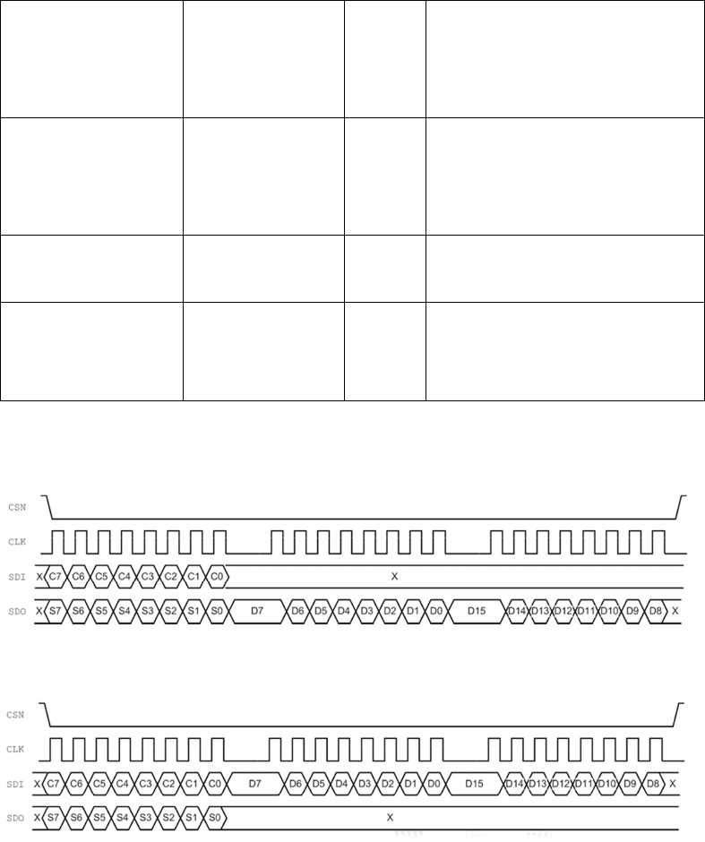
SPI Timing
SPI Read Command
SPI Write Command
9
SPI NOP Command
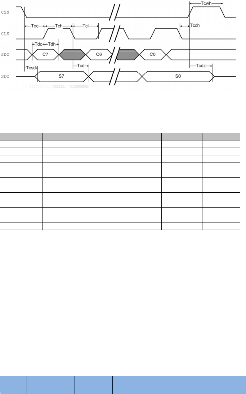
Table2: SPI Timing
Symb
o
l
Pa
r
a
m
e
te
r
s
M
i
n
i
m
u
m
M
a
x
i
m
u
m
U
n
i
ts
Tdc
Data
to
C
L
K
se
tup
3
n
Tdh
C
L
K
t
o
da
ta
h
o
l
d
3
n
Tcsd
C
SN
to
d
a
t
a
va
li
d
3
8
n
Tcd
C
L
K
t
o
da
ta
va
l
i
d
5
5
n
T
c
l
C
L
K
l
o
w
ti
m
e
4
0
n
Tch
C
L
K
h
igh
t
i
m
e
4
0
n
F
C
L
K
C
L
K
fr
e
qu
e
nc
y
0
1
0
MH
T
r
/T
f
C
L
K
r
i
se
&
f
a
l
l
t
i
m
e
1
00
n
Tcc
C
SN
to
C
L
K
se
tup
3
n
Tcch
CLK to CSN
ho
l
d
3
n
s
Tc
w
h
CSN inactive
t
im
e
50
n
s
Tcd
z
C
SN
to
o
u
t
p
ut
h
i
g
h
Z
3
8
n
3.5 SDO STATUS READOUT
By default the SDO will readout the STATUS register during every SPI command input. A feature of
DKL1608-S is that the SDO readout may be set to “RX” focused readout or “FIFO” readout. The
SDO readout is set by STAT_SETUP in the FEATURE register. When the register is set to RX readout
mode, the positions of MAX_RT and TX_FULL are replaced by RSSI2 and RSSI1. In FIFO readout
mode, SDO will read out STATUS_FIFO instead of the STATUS register.
4 REGISTER MAP TABLE
Addresses 0x19, 0x1A, 0x1B, and 0x1F are reserved for test purposes and performance tuning.
Altering them to values other than their POR values may result in chip malfunction.
Reserved bits that are labeled “Unused” do not have any function. Reserved bits that are labeled
“Only ‘0’ allowed” are not to be changed. Modifications to such reserved bits may result in chip
malfunction.
Add
r
es
s
(
hex
)
N
a
m
e
B
i
t
R
e
s
e
t
va
l
ue
T
y
pe
Des
c
ri
p
t
i
o
n

10
00
C
F
G
_
T
O
P
Top-level con
f
i
gu
r
ation
Res
e
r
v
ed
7 0 R/
W
Must be 0 for normal ope
r
at
i
on
M
A
S
K
_
R
X
_
D
R
6 0 R/
W
Mask interrupt caused by RX_DR;
1: interrupt not reflected on IRQ p
i
n; 0:
reflect RX_DR as active
l
o
w
interrupt on
I
RQ
p
i
n
M
A
S
K
_
T
X
_
D
S
5
0
R
/
W
Ma
s
k
i
n
te
r
ru
p
t
c
a
used
b
y
T
X_
DS
;
1: interrupt not reflected on IRQ
pin; 0: reflect TX_DS as active
l
o
w
interrupt on IRQ pin
MASK_MAX_RT
4
0
R/W
Mask interrupt caused by MAX_RT; 1:
interrupt not reflected on IRQ pin; 0: reflect
MAX_RT as active low interrupt on IRQ pin
EN_CRC
3
1
R/W
Enable CRC. Forced high if any of the bits in
EN_AA is high
CRCC
2
0
R/W
CRC scheme
0: 1 byte, 1: 2 bytes
PWR_ON
1
0
R/W
1: power
-
up, 0, power
-
down
RX_ON
0
0
R/W
1: PRX, 0: PTX
01 EN_AA Auto-acknowledgement settings
Reserved
7:6
0
R/W
Unused
ENAA_P5
5
1
R/W
Enable AA on data pipe 5
ENAA_P4
4
1
R/W
Enable AA on data pipe 4
ENAA_P3
3
1
R/W
Enable AA on data pipe 3
ENAA_P2
2
1
R/W
Enable AA on data
pipe 2
ENAA_P1
1
1
R/W
Enable AA on data pipe 1
ENAA_P0
0
1
R/W
Enable AA on data pipe 0
02 EN_RXADDR Enable RX addresses
Reserved
7:6
0
R/W
Unused

11
ENRX_P5
5
0
R/W
Enable data pipe 5
ENRX_P4
4
0
R/W
Enable data pipe 4
ENRX_P3
3
0
R/W
Enable
data pipe 3
ENRX_P2
2
0
R/W
Enable data pipe 2
ENRX_P1
1
1
R/W
Enable data pipe 1
ENRX_P0
0
1
R/W
Enable data pipe 0
03 SETUP_AW Address width & timing setup
Reserved
7:4
0
R/W
Unused
Reserved
3:2
11
R/W
Reserved setting, must be set to 11
Reserved
1:0
11
R/W
Reserved setting, must be set to 11
04 SETUP_RETR Automatic retransmission setup
ARD[3:0]
7:4
0000
R/W
Automatic retransmission delay
0000: wait 250uS
0001: wait 500uS
.
ARC[3:0]
3:0
0011
R/W
Auto retransmit count
0000: disabled
0001: up to 1 re-transmit on fail of
AA
05 RF_CH RF channel
Reserved
7
0
R/W
Unused
RF_CH[6:0]
6:0
0x02
R/W
Set frequency channel in 1 MHz increment,
0x00 is 2400 MHz
06 SETUP_RF RF settings
EN_CW
7
0
R/W
Enable continuous carrier when set high
Confirm during chip verification
EN_PRBS
6
0
R/W
Enable PRBS bit stream when set high;
EN_CW also needs to be enabled
RF_DR_LOW
5
0
R/W
See RF_DR_HIGH

12
TX_ATTN
4
0
R/W
TX low
-
power mode
Confirm actual attenuation level
RF_DR_HIGH
3
0
R/W
[RF_DR_LOW, RF_DR_HIGH]
00: 1Mbps
01: 2Mbps
10: 250kbps
RF_PWR[1:0]
2:1
01
R/W
Set RF output power in TX mode
00: -18 dBm
01: -12 dBm
10:
-
6 dBm
Reserved
0
0
R/W
Unused
07 STATUS
Status (read
-
out from SDO pin during SPI
command word input);
SDO output may be adjusted
Reserved
7
0
R/W
Unused
RX_DR
6
0
R/W
Data ready RX FIFO interrupt. Asserted
when new data arrives at RX FIFO. Write 1
to clear bit
TX_DS
5
0
R/W
Data sent TX FIFO interrupt.
Asserted when packet transmitted. If
auto-ACK is activated, this bit is set high
only when ACK is received. Write 1 to clear
MAX_RT
4
0
R/W
Maximum number of TX retransmit
interrupt. Write 1 to clear bit. If MAX_RT is
asserted it must be cleared to enable
further operation
RX_P_NO[2:0]
3:1
111
R
Data pipe number for the payload available
for reading from RX_FIFO
000~101: data pipe number (0~5)
TX_FULL
0
0
R
0: TX FIFO available
1: TX FIFO full
08 OBSERVE_TX Transmission observation
PLOS_CNT[3:0]
7:4
0000
R
Count lost packets. Overflow protected to
15, and stops at maximum value until reset.
Counter reset by writing to RF_CH
ARC_CNT[3:0]
3:0
0000
R
Count retransmitted packets.
Counter resets
when transmission of a new packet starts
09 RSSI TSSI and RSSI indicator/control
Reserved
7
0
R/W
Must be 0 for normal operation
Reserved
6
0
R/W
Must be 0 for normal operation
Reserved
5
0
R/W
Must be 0 for normal operation

13
EN_RSSI
4
0
R/W
Enable RSSI
Reserved
3
0
R
Reserved register readout
Reserved
2
0
R
Reserved register readout
RSSI2
1
0
R
RSSI indicator at threshold 2
RSSI1
0
0
R
RSSI indicator at threshold 1
0A RX_ADDR_P0 39:0
0xE7
E7E7
E7E7
R/W
RX address data pipe 0. 5 bytes maximum.
LSB byte written first. Number of bytes used
set by SETUP_AW.
0B RX_ADDR_P1 39:0
0xC2
C2C2
C2C2
R/W
RX address data pipe 1. 5 bytes maximum.
LSB byte written first. Number of bytes used
set by SETUP_AW.
0C RX_ADDR_P2 7:0 0xc3 R/W RX address data pipe 2. Only LSB are set,
MSB bytes use RX_ADDR_P1[39:8]
0D RX_ADDR_P3 7:0 0xc4 R/W RX address data pipe 3. Only LSB are set,
MSB bytes use RX_ADDR_P1[39:8]
0E RX_ADDR_P4 7:0 0xc5 R/W RX address data pipe 4. Only LSB are set,
MSB bytes use RX_ADDR_P1[39:8]
0F RX_ADDR_P5 7:0 0xc6 R/W RX address data pipe 5. Only LSB are set,
MSB bytes use RX_ADDR_P1[39:8]
10 TX_ADDR 39:0
0xE7
E7E7
E7E7
R/W
TX address. Used for PTX only. Set
RX_ADDR_P0 equal to this address to
handle auto acknowledgement
11 RX_PW_P0
Reserved
7:6
00
R/W
Unused
RX_PW_P0
5:0
0
R/W
Number of bytes in RX payload in data pipe
0 (1 to 32). 0: pipe not used
12 RX_PW_P1
Reserved
7:6
00
R/W
Unused
RX_PW_P1
5:0
0
R/W
Number of bytes in RX payload in
data pipe
1 (1 to 32). 0: pipe not used
13 RX_PW_P2
Reserved
7:6
00
R/W
Unused
RX_PW_P2
5:0
0
R/W
Number of bytes in RX payload in data pipe
2 (1 to 32). 0: pipe not used
14 RX_PW_P3

14
Reserved
7:6
00
R/W
Unused
RX_PW_P3
5:0
0
R/W
Number of
bytes in RX payload in data pipe
3 (1 to 32). 0: pipe not used
15 RX_PW_P4
Reserved
7:6
00
R/W
Unused
RX_PW_P4
5:0
0
R/W
Number of bytes in RX payload in data pipe
4 (1 to 32). 0: pipe not used
16 RX_PW_P5
Reserved
7:6
00
R/W
Unused
RX_PW_P5
5:0
0
R/W
Number of bytes in RX payload in data pipe
5 (1 to 32). 0: pipe not used
17 STATUS_FIFO FIFO status
Reserved
7
0
R/W
Unused
TX_REUSE
6
0
R
Used for a PTX device
Pulse the rfce high for at least 10µs to Reuse
last
transmitted
payload. TX payload
TX_FULL
5
0
R
1: TX FIFO full 0: available slots in
TX FIFO
TX_EMPTY
4
1
R
1: TX FIFO empty 0: data in TX FIFO
Reserved
3:2
0
R
Reserved register readout
RX_FULL
1
0
R
1: RX FIFO full 0: available slots in
RX FIFO
RX_EMPTY
0
1
R
1: RX FIFO empty 0: RX FIFO full
18 RSSIREC RSSI recorder feature
Reserved
31:2
6
111
W
Reserved
Reserved
25:2
2
0110
R
Reserved
RSSI2_VREF_S
EL[2:0]
21:1
9
000
W
RX RSSI VREF2 setting
000: -59 dBm, +4dB/step
111: out of range
RSSI1X_VREF_
SEL[2:0]
18:1
6
000
W
RX RSSI VREF1 setting
000:-69 dBm, +4dB/step

15
RSSIREC2[7:0
]
15:8
01110
010
R
RSSI2 recorder, MSB is most
recent recording, any write command on
this register will flush RSSI setting; when
RX_ON=0, PWR_ON=0 & CE=0, register will
RSSIREC1[7:0
]
7:0
01000
001
R
RSSI1 recorder, MSB is most
recent
recording, any write command on this
register will flush RSSI setting; when
RX_ON=0, PWR_ON=0 & CE=0, register will
1C DYNPD Dynamic payload length
Reserved
7:6
00
R/W
Unused
DPL_P5
5
0
R/W
Set 1 to enable dynamic payload
length data
pipe 5 (requires EN_DPL & ENAA_P5)
DPL_P4
4
0
R/W
Set 1 to enable dynamic payload length data
pipe 4 (requires EN_DPL & ENAA_P4)
DPL_P3
3
0
R/W
Set 1 to enable dynamic payload length data
pipe 3 (requires EN_DPL & ENAA_P3)
DPL_P2
2
0
R/W
Set 1 to enable dynamic payload length data
pipe 2 (requires EN_DPL & ENAA_P2)
DPL_P1
1
0
R/W
Set 1 to enable dynamic payload length data
pipe 1 (requires EN_DPL & ENAA_P1)
DPL_P0
0
0
R/W
Set 1 to enable dynamic payload length data
pipe 0 (requires EN_DPL & ENAA_P0)
1D FEATURE Features
STAT_SETUP[1
:0]
7:6
00
R/W
Adjust the output of SDO during command
input
00: default, SDO output is STATUS
01: RX readout mode, the SDO output
MAX_RT and TX_FULL bit is replaced by
RSSI1 and RSSI2 readout
Reserved
5:3
000
R/W
Unused
EN_DPL
2
0
R/W
Set 1 enables dynamic payload
length
EN_ACK_PAY
1
0
R/W
Set 1 enables payload on ACK
EN_DYN_ACK
0
0
R/W
Set 1 enables the
W_TX_PAYLOAD_NOACK
command
1F RESERVED Reserved register
Reserved
7:0
0
R/W
8’h00: default settings