Hanatech ULTRASCAN AUTOMOTIVE HANDHELD SCANTOOL User Manual User s Manual G
Hanatech Co.,Ltd AUTOMOTIVE HANDHELD SCANTOOL User s Manual G
UserManual.wiki
>
Hanatech
>
ULTRASCAN User Manual
USERS MANUAL
Navigation menu
Upload a User Manual
Namespaces
Wiki Guide
HTML
PDF
Info
Views
User Manual
Discussion / Help
Navigation
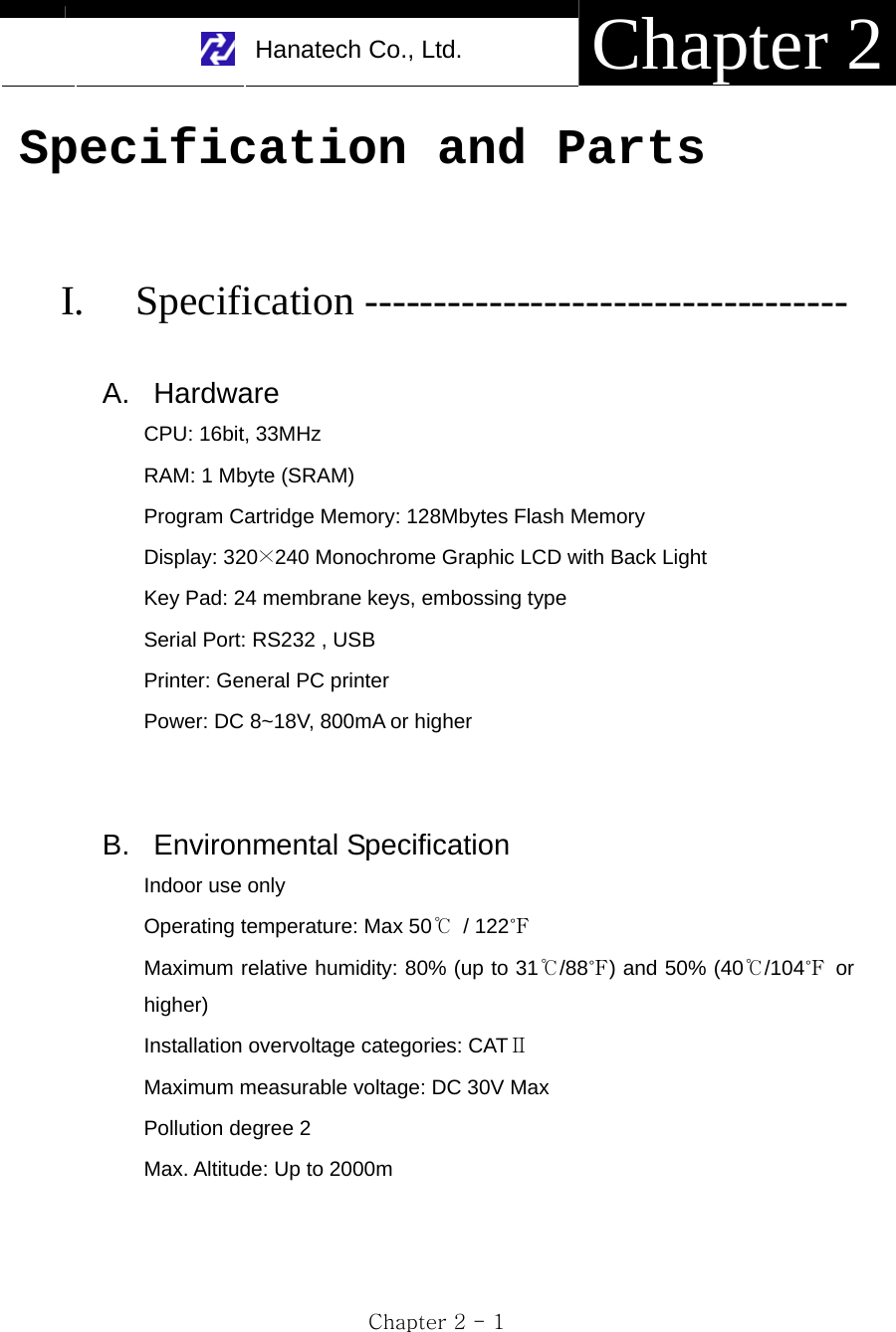
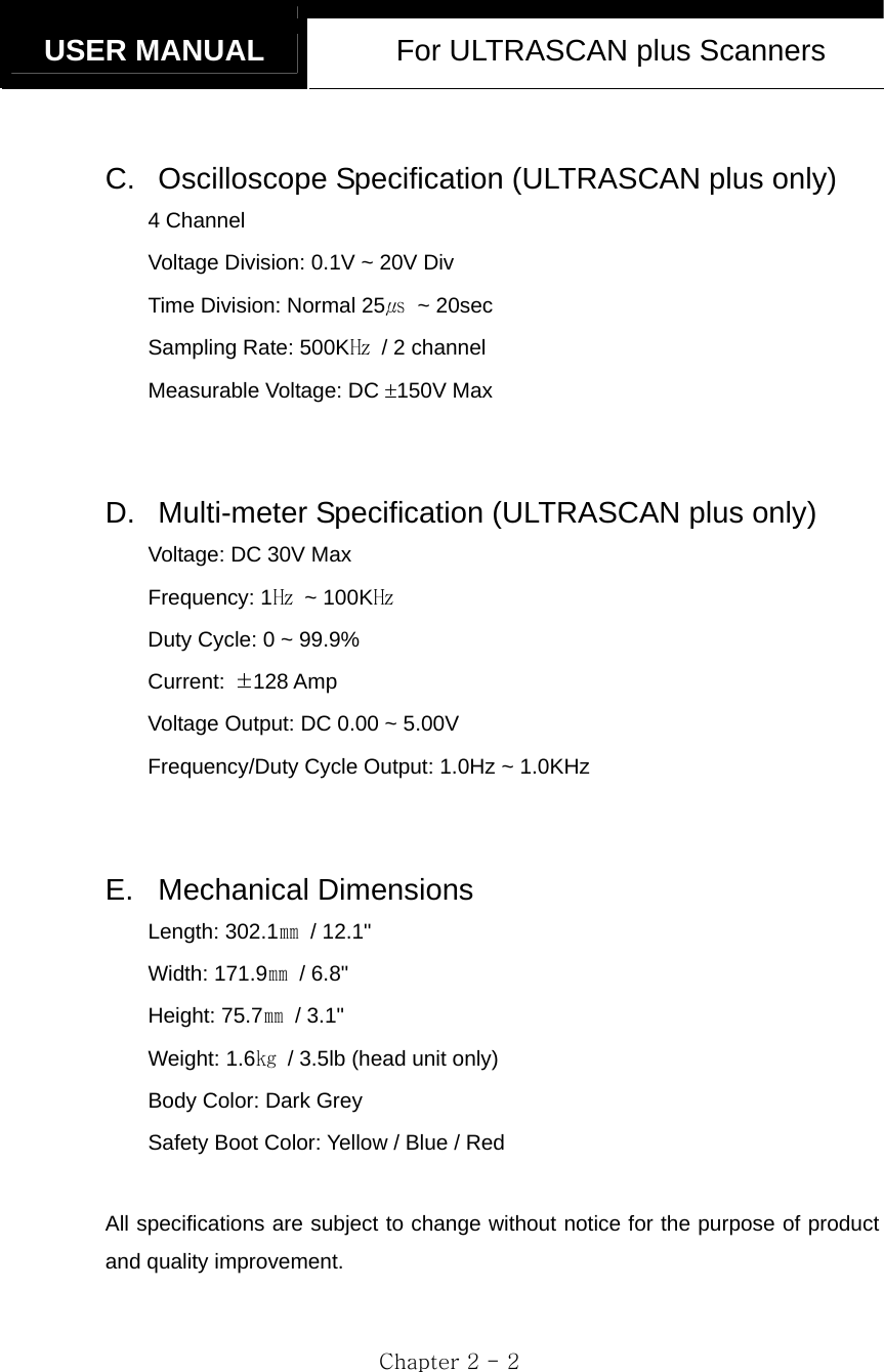
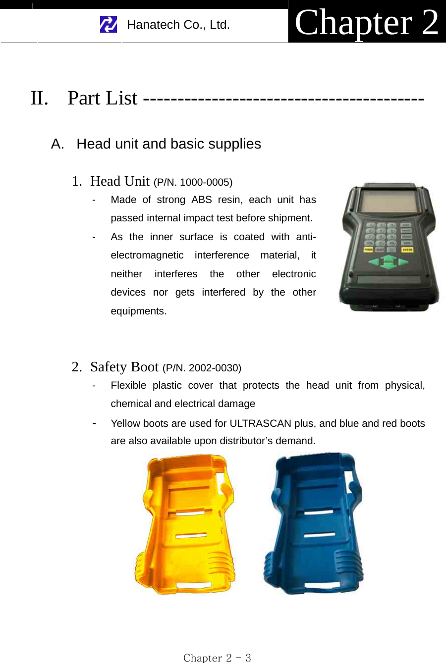
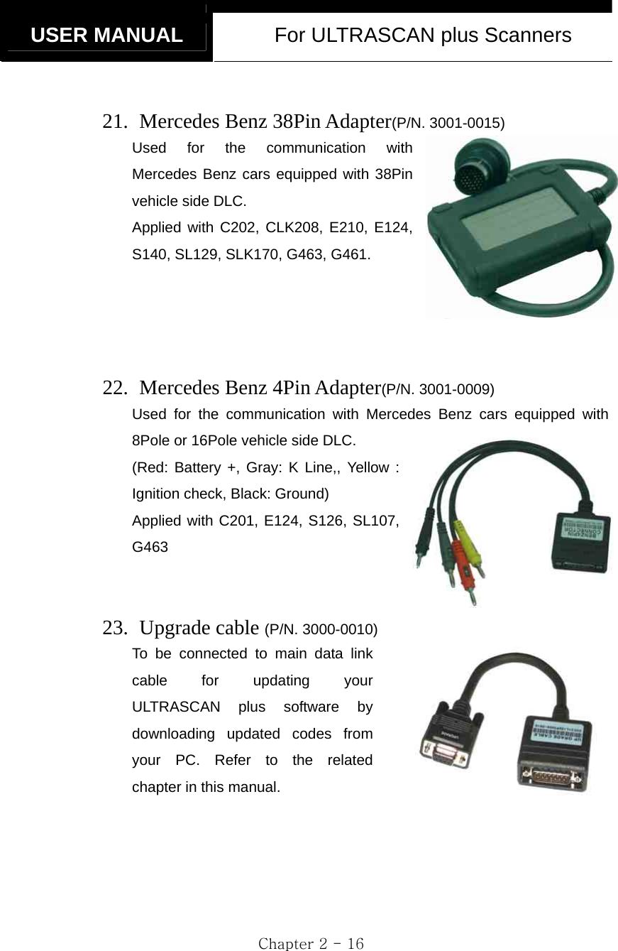
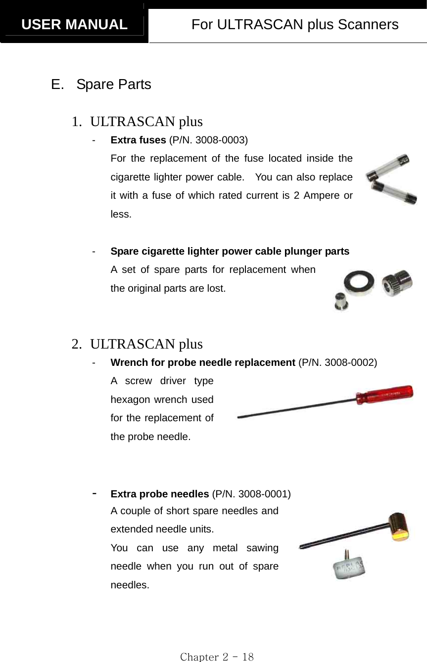
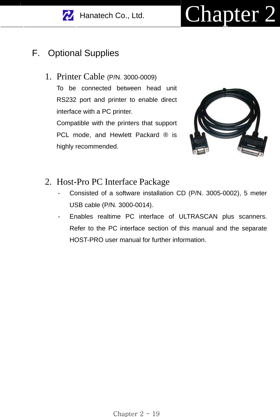
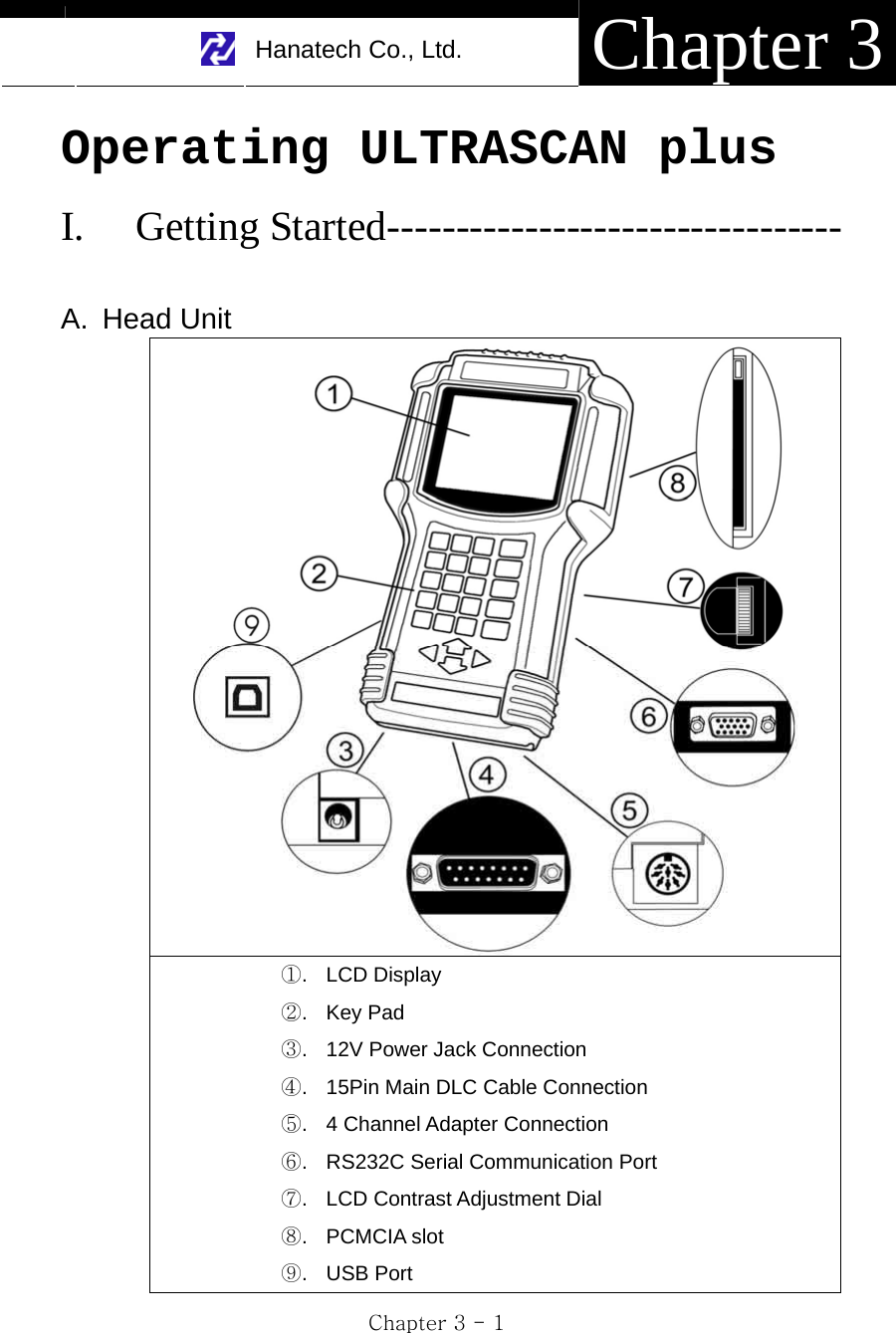
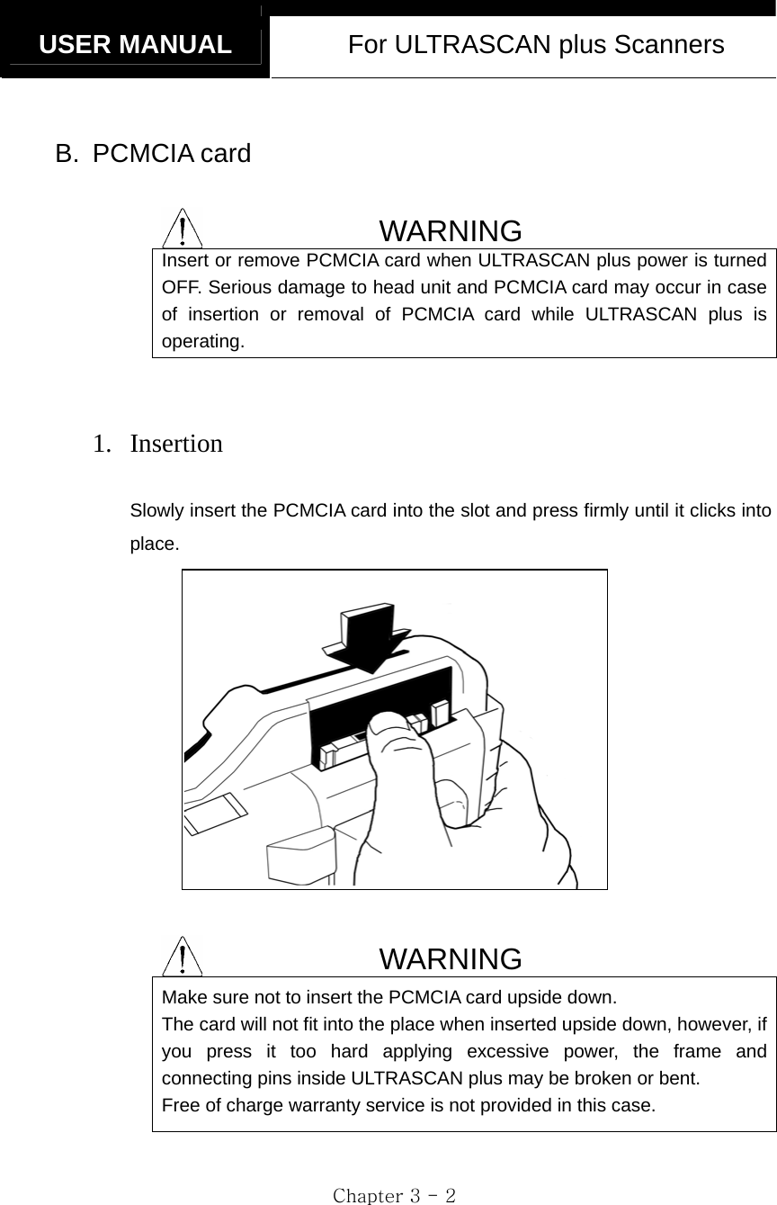
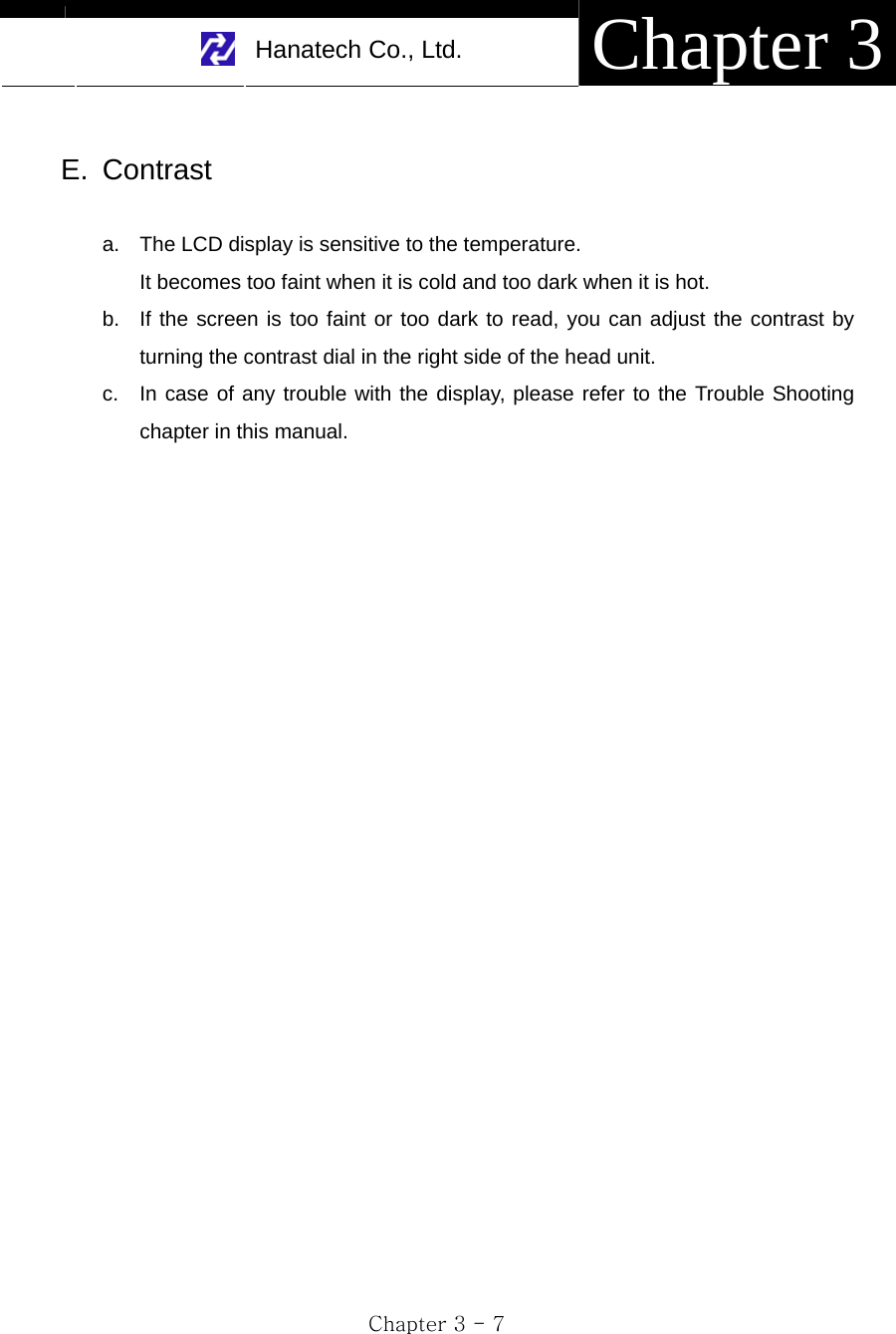
![Hanatech Co., Ltd. Chapter 2 Chapter 2 - 17 D. Software Cartridge - Contains vehicle information and operating software for ULTRASCAN plus scanners. - The appearance and measurements for ULTRASCAN plus cartridges complies with standard PCMCIA, however, inner circuits are of Hanatech’s own design. Therefore, you can neither use it with the other equipment nor copy its contents to the other standard PCMCIA. WARNING MAKE SURE TO TURN POWER OFF BEFORE REMOVING OR INSERTING A CARTRIDGE. It is extremely dangerous to insert or remove a PCMCIA card while the head unit is turned on. Both PCMCIA card and head unit can be critically damaged and break down. Always turn power off by pressing the [POWER] key or removing power supply cable from the head unit before inserting or removing a PCMCIA card..](https://usermanual.wiki/Hanatech/ULTRASCAN/User-Guide-515797-Page-26.png)
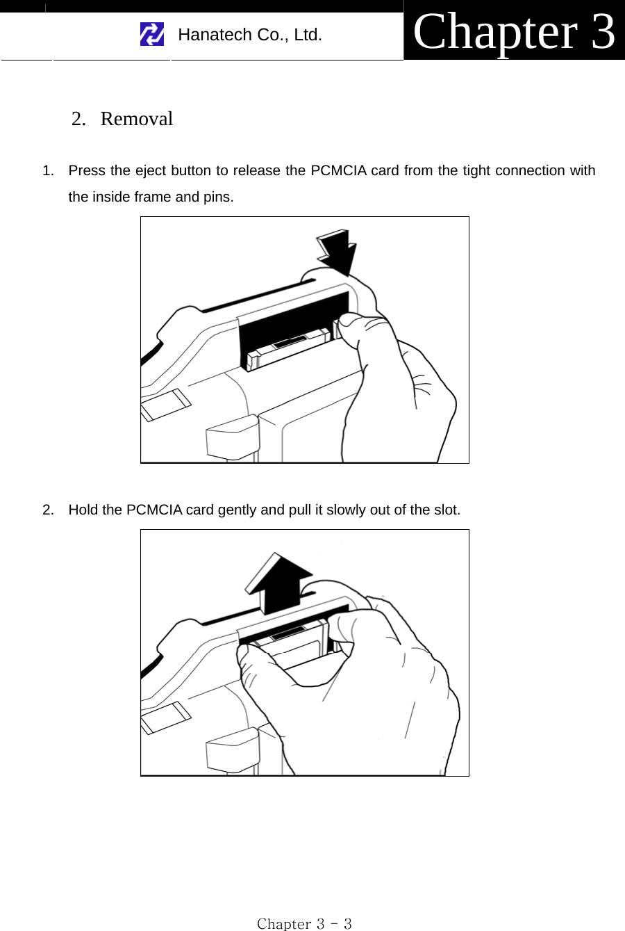
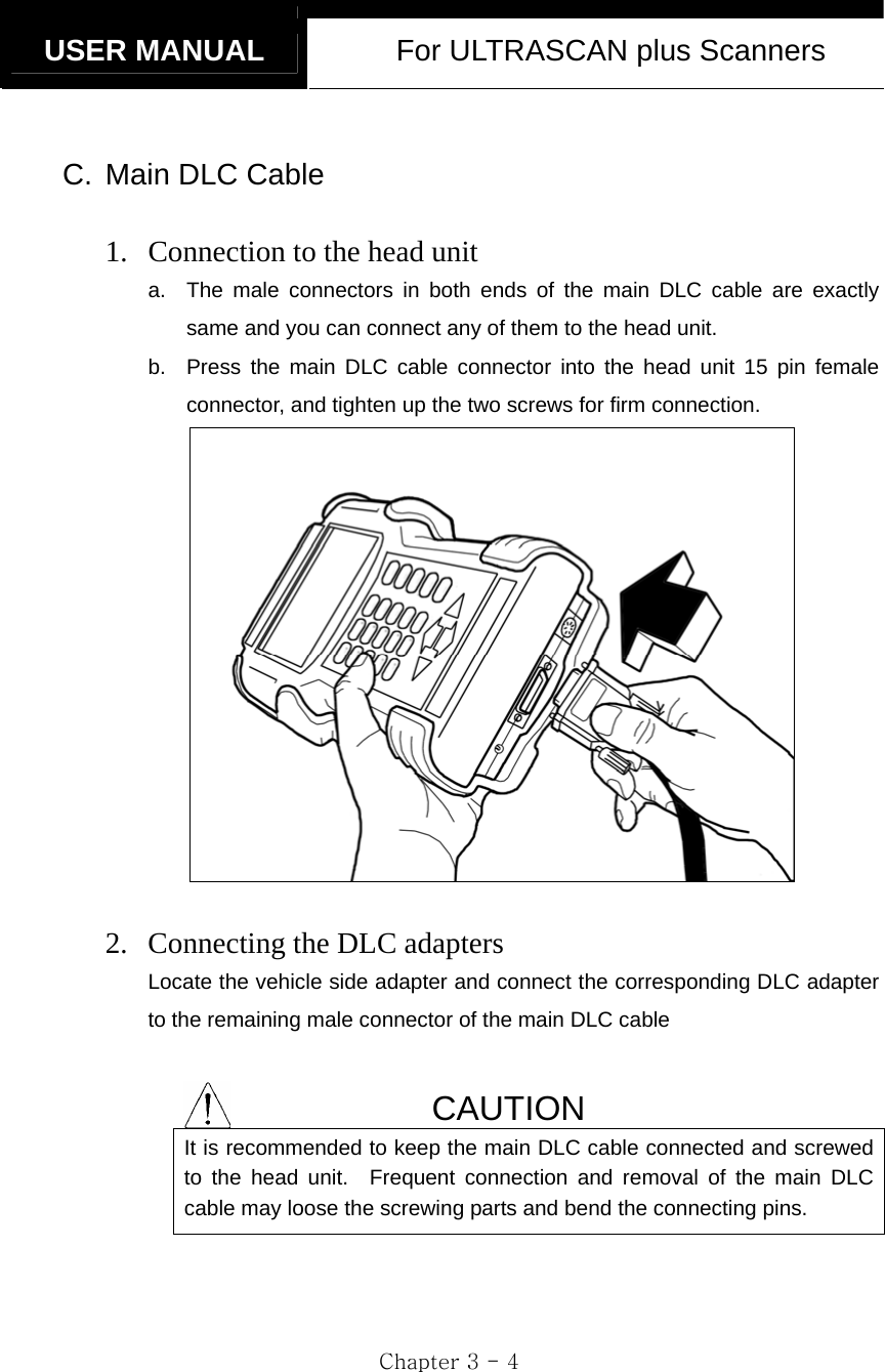
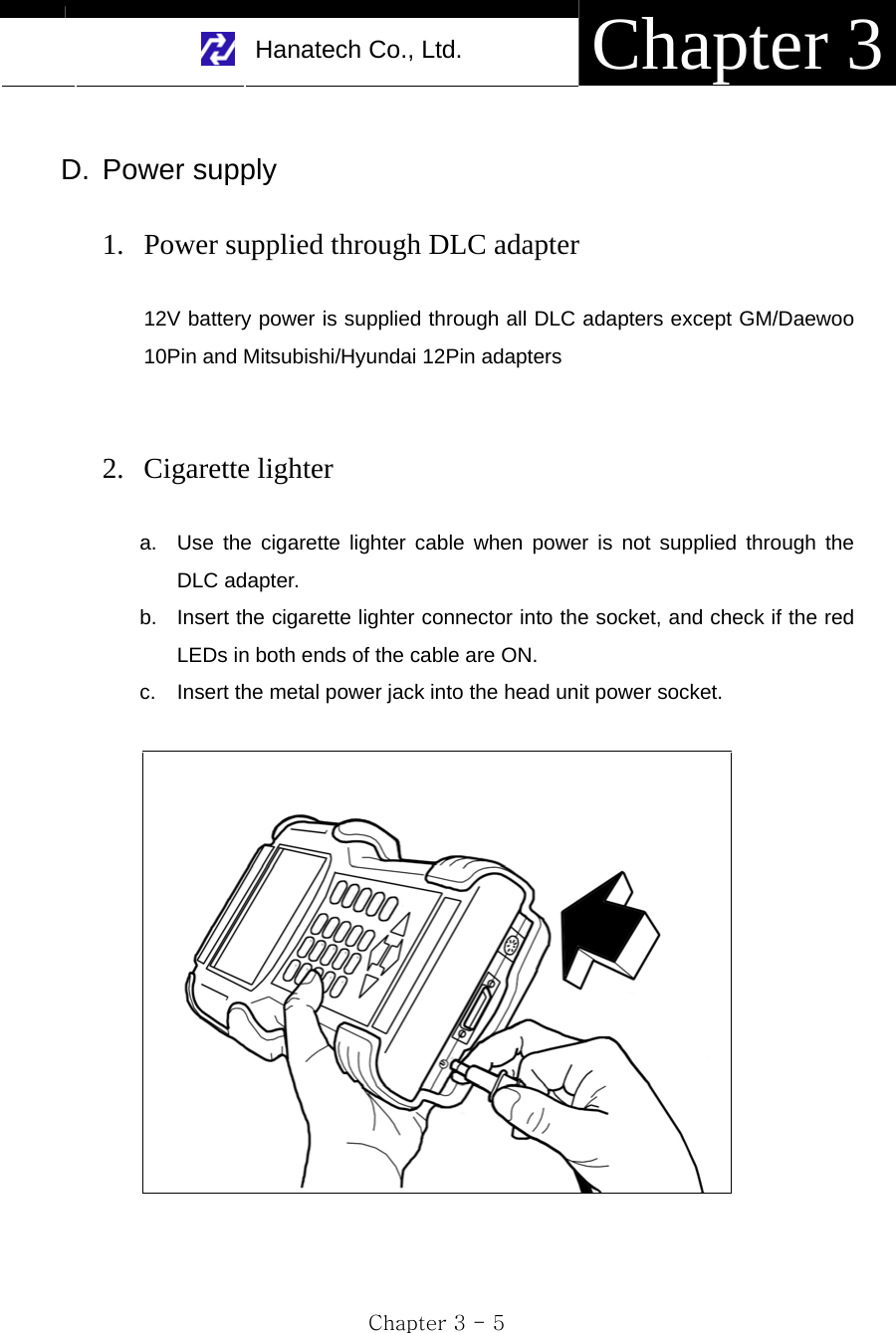
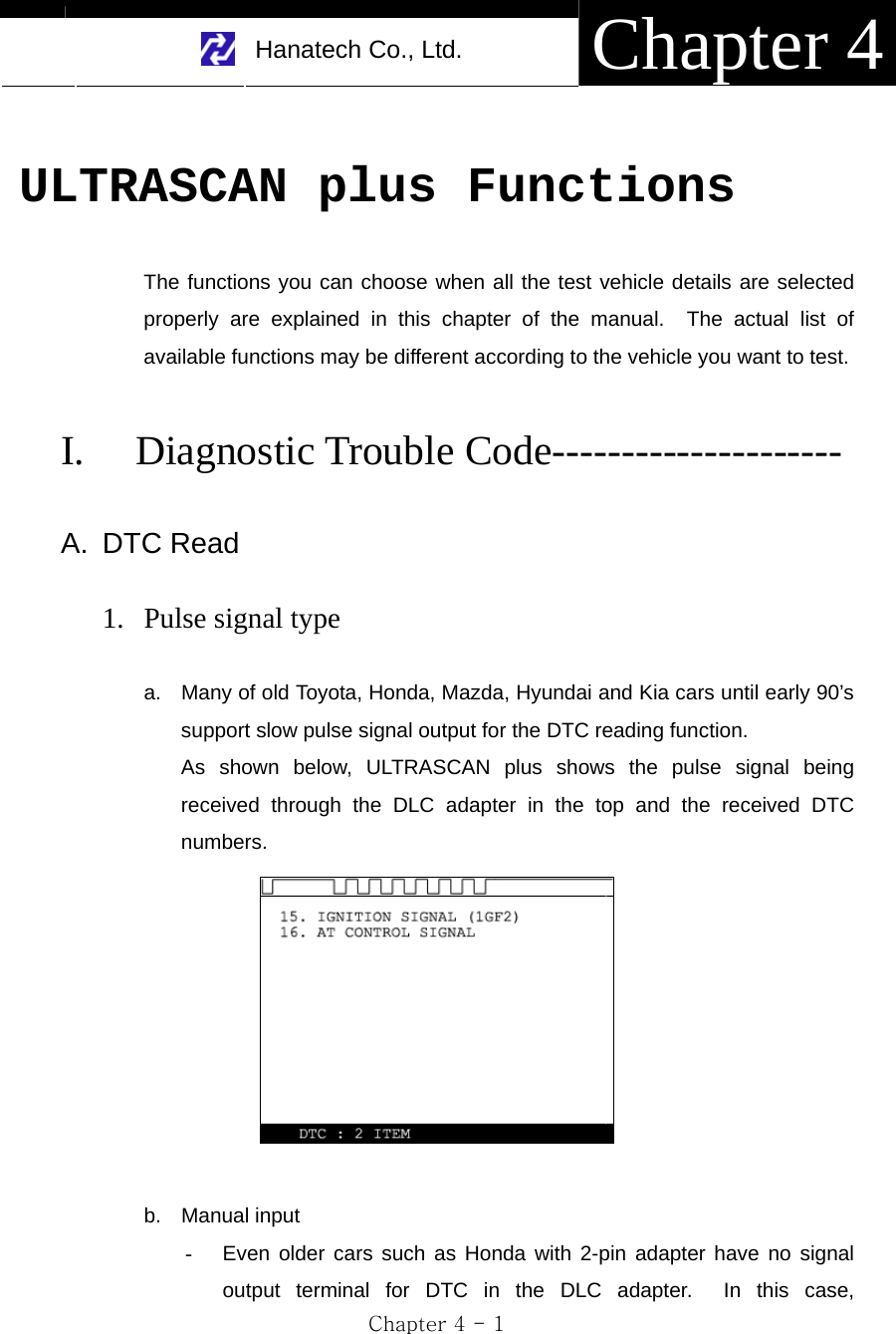
![USER MANUAL For ULTRASCAN plus Scanners Chapter 3 - 6 3. Vehicle battery a. Since the head unit must be placed in the engine compartment when using multimeter, oscilloscope or ignition pattern analysis function, it is necessary to get the power from the vehicle battery. b. Connect the alligator clips of the battery power cable to the battery terminals of correct polarity. Check the red LED on the round socket turns ON. c. Connect the cigarette lighter power cable connector into the battery power cable socket. 4. Power ON Press the [POWER] key of the head unit key pad to turn power ON. To turn power OFF, press the [POWER] key for more than 1 second.](https://usermanual.wiki/Hanatech/ULTRASCAN/User-Guide-515797-Page-34.png)
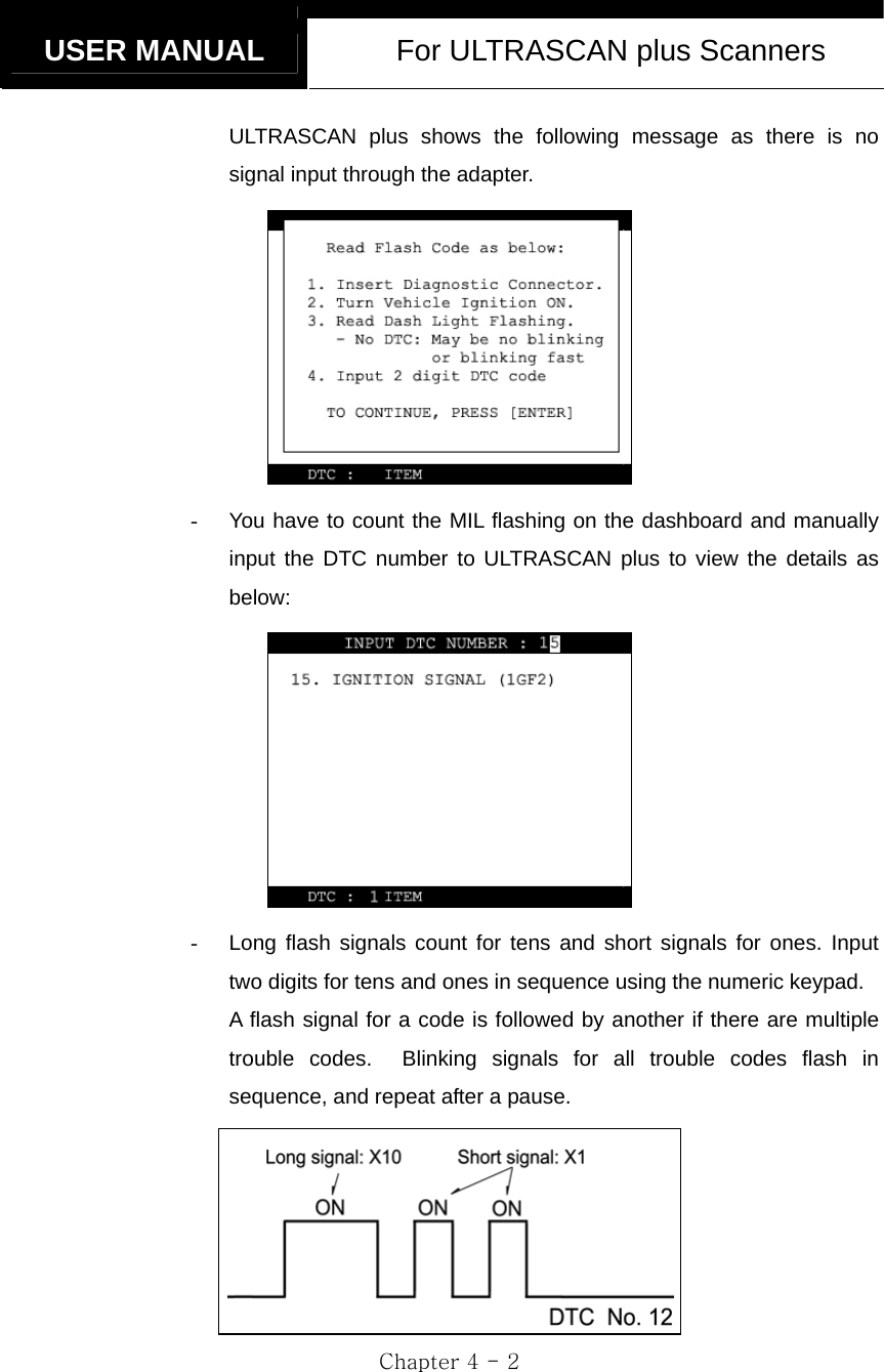
![USER MANUAL For ULTRASCAN plus Scanners Chapter 3 - 8 II. Control Keys ----------------------------------- A. Keypad The keypad is made of chemistry proofing PVC material that prevents contamination and damage from hazardous oily workshop environment. The membrane keypad is designed and tested to maintain its normal operation over 1 million time key press for each. Each key is raised for better tactile feel. The keypad has total of 24 keys. B. Making selection in the menu 1. Numeric Keypad a. Simply press the corresponding number b. This is available only when you are selecting an item of which number is 9 or less. For more than 10, you should locate the highlighted bar on the desired item and press the [ENTER] key.](https://usermanual.wiki/Hanatech/ULTRASCAN/User-Guide-515797-Page-36.png)
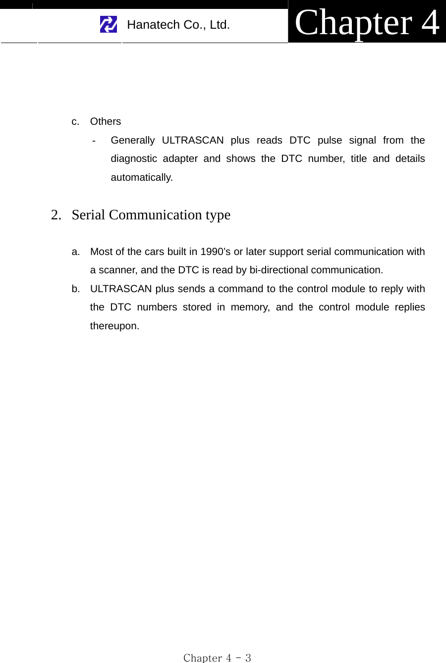
![Hanatech Co., Ltd. Chapter 3 Chapter 3 - 9 2. Arrow keys ◀ ▶ Page Up/Down ▲▼ Scroll Up/ Down a. Scroll up and down the highlighted bar in the menu by pressing Up/Down arrow keys and press the [ENTER] key to confirm the selection. b. If the menu has more than 12 items, you may have to scroll up or down the pages to make selection. You do not have to pound on Up/Down arrow keys to scroll the whole page. Simply pressing the Left or Right arrow key will shift page to page. Move the highlighted bar by pressing the up/down keys when the desired item appears on the screen, and press the [ENTER] key. C. Function keys 1. POWER a. After connecting appropriate power cable, press this key shortly to turn the ULTRASCAN plus on. b. To turn off, press this key for more than a second until the powering OFF message appears on the screen as shown in the right.](https://usermanual.wiki/Hanatech/ULTRASCAN/User-Guide-515797-Page-37.png)
![USER MANUAL For ULTRASCAN plus Scanners Chapter 3 - 10 2. Back light [ ] a. LCD module of ULTRASCAN plus has an illuminating back panel for better legibility in dark or shady places. b. Press this button to turn the back light ON and OFF. 3. ESC Used to abort an operation of ULTRASCAN plus or move to the upper level menu. 4. HELP a. DTC Read - When a trouble code is detected, you can press this key to view the detailed information of the DTC. - DTC definition, DTC registration conditions and check points are provided (For Korean and Malaysian cars only as of May, 2003) b. Service Data (Data Stream) - While live data is being displayed on the screen, select a live data item by moving the highlighted bar, and press this key to view the detailed information about the selected item. - Standard value and technical explanations are provided. (For Korean and Malaysian cars only as of May, 2003) 5. PRINT a. When a printer is connected to ULTRASCAN plus via printer cable, press this key to print out the current display: DTC list, a set of data stream, oscilloscope waveform or ignition pattern. b. Refer to the Optional Parts section for detailed information on the printer cable.](https://usermanual.wiki/Hanatech/ULTRASCAN/User-Guide-515797-Page-38.png)
![Hanatech Co., Ltd. Chapter 3 Chapter 3 - 11 III. Configuration ---------------------------------- Press the [6] key from the initial function menu to proceed to the configuration menu. You can check the version numbers of the software packages contained in the PCMCIA card, test the keypad and LCD, set up sound and language options and download software updates in the configuration menu. A. Software Information When you select [1. SOFTWARE INFORMATION] in the configuration menu, a list of software packages contained in the PCMCIA card will appear as below: Should you get any update files from your local distributor or from Hanatech website, please compare the version number and last update date to check if the update is necessary.](https://usermanual.wiki/Hanatech/ULTRASCAN/User-Guide-515797-Page-39.png)
![USER MANUAL For ULTRASCAN plus Scanners Chapter 3 - 12 B. Special functions 1. Download software - You can download the software updates from your PC when you select [1. DOWNLOAD SOFTWARE]. - Instructions will be given separately whenever an update is available. Contact your local distributor for the availability of update frequently and keep posted of such events. 2. Language - You can select provided language. English and Spanish languages are available for selection as of May, 2003. - Hanatech is translating the menu and messages of ULTRASCAN plus to various local languages such as Russian, Arabic and Chinese for convenience of non-English speaking customers, and the each language will be provided as an update when the translation is completed. 3. Sound - You can toggle ON and OFF the key sound. 4. Save Configuration - If you have made any change in this [Special Function] menu, you have to save the configuration to make such changes effective. - Press the [4] key to save the changes in configuration](https://usermanual.wiki/Hanatech/ULTRASCAN/User-Guide-515797-Page-40.png)
![Hanatech Co., Ltd. Chapter 4 Chapter 4 - 5 C. DTC Help tips a. Help tips are provided when you press the [HELP] key after locating the highlighted bar on one of the detected trouble code(s). This function is available when ULTRASCAN plus detects one or more trouble code(s) b. Help tips including trouble code definition, conditions and check points are provided for all Korean cars and Malaysian cars as of May 2003. Wiring diagrams are also provided for Korean cars of 2000 model-year or older. c. Press the [ESC] key to return to DTC list.](https://usermanual.wiki/Hanatech/ULTRASCAN/User-Guide-515797-Page-45.png)
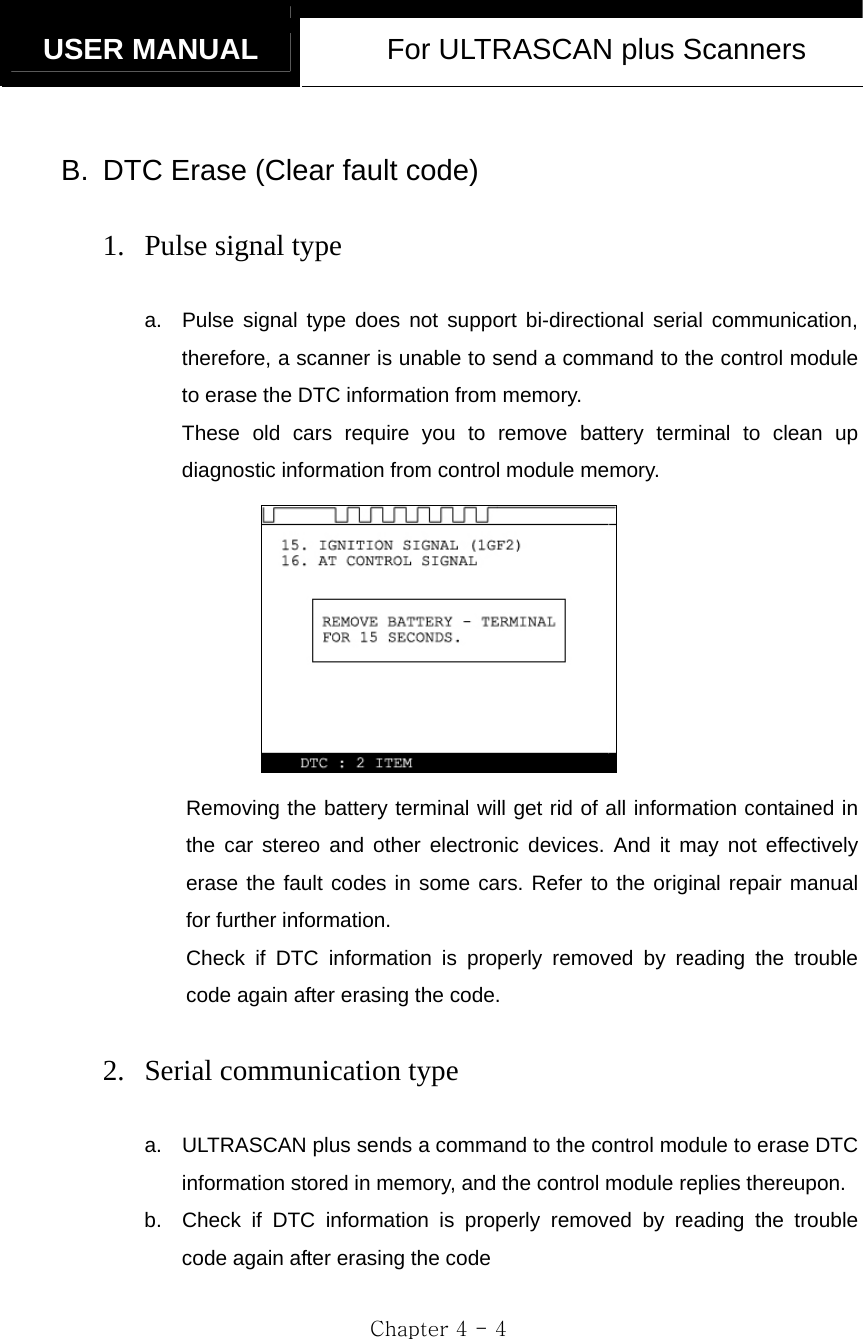
![USER MANUAL For ULTRASCAN plus Scanners Chapter 4 - 6 II. Current Data ----------------------------------- (= Data Stream, Live Data, Service Data) A. Pulse Signal Type a. Data stream is not generally supported for this type of old cars because the speed of pulse signal communication is too slow to read the data stream variables. b. Some of old Toyota cars using 17-pin rectangular adapter exceptionally support data readings as the system supports relatively high speed pulse signal communication. B. Serial Communication Type a. Most of control systems with serial communication support data stream function. Select [Current data] from the menu, then the data readings follow. b. Some systems like SRS or ABS may be designed not to support data stream intentionally by the car make while the other systems are supported. A scanner is a passive tool that reads information from the control system, and it is unable to actively generate information that the system does not provide.](https://usermanual.wiki/Hanatech/ULTRASCAN/User-Guide-515797-Page-46.png)
![Hanatech Co., Ltd. Chapter 4 Chapter 4 - 7 C. Data Freeze The [Data Freeze] function places the selected data stream variable on top of the LCD screen so that the user can check and compare desired sensor values continually without having to scroll up and down. This function is different from ‘Freeze Frame Data’ function of Generic OBD2. 1) Step One Select a desired sensor using the [◀][▶] and the [▲][▼] keys. 2) Step Two Press the [ENTER] key to freeze the selected sensor. i.e., when O2 sensor and MAP sensor are selected and frozen, these sensor values will be placed at the top of the display as below : 3) Step Three Up to five sensors may be frozen at a time. For example, if the Injection Time, which can be shown when scrolled down, is selected and frozen, Injection Time value will be placed below the previously frozen O2 and MAP sensor.](https://usermanual.wiki/Hanatech/ULTRASCAN/User-Guide-515797-Page-47.png)
![USER MANUAL For ULTRASCAN plus Scanners Chapter 4 - 8 D. Data Graph ULTRASCAN plus provides the [Data Graph] function for more efficient data analysis. a When you press the [1] key after locating the highlight bar on the desired sensor, the sensor data graph will be displayed as shown below. b You can display up to 3 graphs in a screen by choosing the sensors as previously explained [Data Freeze] procedure - Press the [Enter] key after locating the highlight bar on the desired sensor, and then press the [1] key. When more than 4 sensors are selected, the graphs of upper three sensors will be displayed.](https://usermanual.wiki/Hanatech/ULTRASCAN/User-Guide-515797-Page-48.png)
![Hanatech Co., Ltd. Chapter 4 Chapter 4 - 9 c For each sensor data graph, the name of the sensor and its current value will be simultaneously displayed together. d To change the sensor, go back to the previous Service Data display by pressing the [Esc] key, and then choose other sensors. e To halt the graph output, press the [ENTER] key. It will resume when you press the [ENTER] key again.](https://usermanual.wiki/Hanatech/ULTRASCAN/User-Guide-515797-Page-49.png)
![USER MANUAL For ULTRASCAN plus Scanners Chapter 4 - 10 E. Help tips a When you press the [HELP] key after locating the highlight bar on a certain data stream variable, the help message will be displayed. This works the same for detected Trouble Codes in [Self Diagnosis] function. b Detailed information including conditional standard range on the selected sensor will be displayed as shown below. c Press the [ESC] key to go back to the data stream display.](https://usermanual.wiki/Hanatech/ULTRASCAN/User-Guide-515797-Page-50.png)
![USER MANUAL For ULTRASCAN plus Scanners Chapter 4 - 12 A. Menu Selection a Choose [ACTUATION TEST] from the function Selection Menu b The name of the actuator to be tested, test method and the test condition are shown in the display. Available actuators, test methods and conditions may differ in each vehicle. B. Test Start 1. Selecting Test Item a Choose an actuator to test from the menu by using the [▲] and [▼] keys. b Check the test conditions and press the [ENTER] key when all the conditions are met. 2. Testing a [TESTING...] message will be displayed during the actuation test Test method means how the actuation test will be performed. Check the actual reaction of the actuator](https://usermanual.wiki/Hanatech/ULTRASCAN/User-Guide-515797-Page-52.png)
![Hanatech Co., Ltd. Chapter 4 Chapter 4 - 13 b In the example below, the injector will stop injecting fuel for 6 seconds while engine is idling, and it will make engine stall or unstable. c Testing a fan or an injector is easy to check the proper reaction as it generates distinctive changes in vehicle condition such as fan whining or unstable idling. However, valves or motors are generally tested while engine is stopped and all you can hear may be a small and unclear electric buzzing sound. Test in a quite place and observe the test results carefully. d When the test is completed, the [TEST COMPLETE] message will be displayed. You can choose other actuators by using the [▲] and [▼] keys. Press the [ESC] key to quit test mode.](https://usermanual.wiki/Hanatech/ULTRASCAN/User-Guide-515797-Page-53.png)
![USER MANUAL For ULTRASCAN plus Scanners Chapter 4 - 14 IV. Black Box -------------------------------------- (= Record Replay) Just like the 'Black Box' or a ‘flight recorder’ of an aircraft, ULTRASCAN plus can 'record' data stream during the vehicle drive test and the recorded data can be 'retrieved' later for intensive analysis of vehicle's condition. ULTRASCAN plus has a menu when selecting Japanese cars, so called “Record Replay” same as Black Box function and you can understand “Record Replay” as Black Box function. A. Function selection Choose [#. Black Box Data] from the [Function Selection Menu] after selecting Origin, Car Manufacturer, Model name and system to test.](https://usermanual.wiki/Hanatech/ULTRASCAN/User-Guide-515797-Page-54.png)
![Hanatech Co., Ltd. Chapter 4 Chapter 4 - 15 B. Capacity a During a normal test, the [Data Stream] frames pass by in rapid succession, and cannot be recalled unless the data has been saved. Thanks to its extensive internal memory, ULTRASCAN plus can record up to 2040 frames of Data Stream for multiple cars. b By loading the recorded data, you can diagnose sensor data frame to frame without missing a single critical moment. C. Memory Check a. ULTRASCAN plus checks its internal memory before it starts recording Black Box data. If there is no sufficient free memory space available, ULTRASCAN plus will suggest deleting one or more of previous record(s). b. Press the [ERASE] key to proceed, then a list of saved data will follow. Locate the highlight bar on data to delete, and press the [ENTER] key. A query for your confirmation will follow. Press the [YES] key to erase otherwise press the [NO] key.](https://usermanual.wiki/Hanatech/ULTRASCAN/User-Guide-515797-Page-55.png)
![USER MANUAL For ULTRASCAN plus Scanners Chapter 4 - 16 D. PID(Live data parameter) selection a You are required to select the parameters to record. b ULTRASCAN plus will show you the whole live data parameters available in the control system you selected. Locate the highlight bar on the desired parameter and press the [ENTER] key. Selected parameter will be marked star(*). You can also deselect the parameter by repeating the procedure. c You can select up to 40 PIDs to record. Press the [ESC] key when the selection is completed, then ULTRASCAN plus will start recording data.](https://usermanual.wiki/Hanatech/ULTRASCAN/User-Guide-515797-Page-56.png)
![Hanatech Co., Ltd. Chapter 4 Chapter 4 - 17 E. Trigger Modes There are three trigger modes in the black box function. a Continuous Record Mode (No trigger mode) - ULTRASCAN plus will record live data of selected parameters up to 2040 frames or until you press the [ESC] key. - Percentile memory usage and sampling time(frequency) will appear in the center of the screen while recording data, and the actual live data values will remain unchanged. - Since no DTC trigger is applied in this mode, number of “Before DTC” frames will remain 0, and the “After DTC” will keep increasing as the more frames are recorded.](https://usermanual.wiki/Hanatech/ULTRASCAN/User-Guide-515797-Page-57.png)
![USER MANUAL For ULTRASCAN plus Scanners Chapter 4 - 18 b Automatic Trigger Mode (Triggered by DTC) - ULTRASCAN plus will keep recording live data of selected parameters up to 128 frames. - Once a DTC is detected or the [ESC] key is pressed by the user, it will proceed with recording remaining frames up to 2,040 or until you abort. - This function will let you have a set of data stream before and after the ECM’s DTC recognition when you perform the test drive. - Before DTC, you will see the Live Data of the selected parameters keep refreshing, however, once triggered by DTC or [ESC] key stroke, only the percentile process information and sampling frequency will be displayed.](https://usermanual.wiki/Hanatech/ULTRASCAN/User-Guide-515797-Page-58.png)
![Hanatech Co., Ltd. Chapter 4 Chapter 4 - 19 c Manual Trigger Mode - ULTRASCAN plus will keep recording live data of selected parameters up to 128 frames, and once the [ESC] key is pressed by the user, it will proceed with recording remaining frames up to 2040. - The screen display is the same as when selecting the Auto Trigger Mode.](https://usermanual.wiki/Hanatech/ULTRASCAN/User-Guide-515797-Page-59.png)
![USER MANUAL For ULTRASCAN plus Scanners Chapter 4 - 20 F. Saving the recorded data a When the total frame number reaches 2040 or when you press the [ESC] key to abort, a query asking you if you would like to save recorded data or to discard it. Press [YES] to save or [NO] to cancel. b When pressed [YES], a dialog box follows and asks you to input the test date. Enter the date and press the [ENTER] key to save the recorded data to ULTRASCAN plus memory. Pressing the [ESC] key cancels saving data. Date format is DD-MM-YYYY(D-day, M-month, Y-year), and only numeric values are available. c Tested Vehicle model name and control system will be saved as well as the date stamp for future retrieval.](https://usermanual.wiki/Hanatech/ULTRASCAN/User-Guide-515797-Page-60.png)
![Hanatech Co., Ltd. Chapter 4 Chapter 4 - 21 G. Black Box Data Load a You can load saved data by choosing [BLACKBOX RECORD LOAD / ERASE] from the [Car Manufacturer Selection] menu as shown below: b A list of recorded Black Box Data will follow for your selection Up to 4 black box data can be stored in the memory per car manufacturer, therefore, up to 4 saved black box data can be listed in the menu. c The details of recorded data will be displayed for confirmation. If the record is correct, press the [ENTER] key. Press the [ESC] key to abort. d If you want to erase any of these saved data, locate the highlight bar and press the erase key.](https://usermanual.wiki/Hanatech/ULTRASCAN/User-Guide-515797-Page-61.png)
![USER MANUAL For ULTRASCAN plus Scanners Chapter 4 - 22 H. Loaded Blackbox data Loaded black box data has basically the same format as the [Service Data (Live Data Stream)]. See the illustration below. 1. Data format In the lower part of the display, the total number of recorded frames, frame number before and after the DTC(Diagnostic Trouble Code), and the number of DTC detected is displayed. In the example below, you can see that a total of 458 frames were recorded, and data stream currently shown in the main window is of the 336th frame from the beginning. It also tells you that the current frame is the 80th after 2 trouble codes were detected. The live data values may not be realistic as the screen was captured while the scan tool was linked to a simulator. 2. Data Replay a. Press the [YES] key then the saved blackbox data will start replaying. ULTRASCAN plus preserves the refresh time intervals of Black Box data. Therefore, Black Box data is replayed at the same speed as when it was originally recorded.](https://usermanual.wiki/Hanatech/ULTRASCAN/User-Guide-515797-Page-62.png)
![Hanatech Co., Ltd. Chapter 4 Chapter 4 - 23 b. If you want to go forward or backward faster, press the [◀] or [▶] key while replaying. Replay speed will restore to the original speed when the key is released. c. Pressing the [YES] key will pause the replay. You can resume replaying from the frame where it was paused by pressing the [YES] key again. d. Pressing the [NO] key will stop replaying. You can restart replay by pressing the [YES] key again, but it will start from the first frame.](https://usermanual.wiki/Hanatech/ULTRASCAN/User-Guide-515797-Page-63.png)
![USER MANUAL For ULTRASCAN plus Scanners Chapter 4 - 24 3. Graph a As previously explained in section [3. Service Data], data from up to three selected parameter data can be graphed. b Make sure that the Black Box data replay is stopped. If it is being replayed or paused, press the [NO] key to stop replaying completely. c Choose the parameter by locating the highlight bar and pressing the [ENTER] key. The selected parameter will be marked with a triangle as shown below: d Then press the [1] key to view the data in graph format. The line graphs are flat as it is not based on data recorded from the active vehicle.](https://usermanual.wiki/Hanatech/ULTRASCAN/User-Guide-515797-Page-64.png)
![Hanatech Co., Ltd. Chapter 4 Chapter 4 - 25 e Up to 316 frames can be displayed on a single page. If recorded data has more than 316 frames, you can shift to next or previous page by using the [▲] and [▼] keys. f The dotted line indicates from which frame the live data parameter values are being displayed. You can move it left and right with the [◀] and [▶] keys. g Elapsed time and frame number are indicated in the bottom. - Continuous Record (No trigger) Mode: Elapsed time and number of frames from the first frame - Automatic / Manual Trigger (Triggered by DTC or user) Mode: Elapsed time and number of frames from the trigger point (DTC detection or [ESC] key stroke by the user). Before the trigger point will be marked in negative values. h To return to the Black Box Data Display, press the [ESC] key.](https://usermanual.wiki/Hanatech/ULTRASCAN/User-Guide-515797-Page-65.png)
![USER MANUAL For ULTRASCAN plus Scanners Chapter 4 - 26 4. DTC a You can check the DTC(s) found during recording Black Box Data. b Make sure that the Black Box data replay is stopped. If it is being replayed or paused, press the [NO] key to stop replaying completely. c Press the [2] key then the list of DTC(s) will appear as below: d Because Black Box Data is not live or active, you cannot erase DTC(s).](https://usermanual.wiki/Hanatech/ULTRASCAN/User-Guide-515797-Page-66.png)
![Hanatech Co., Ltd. Chapter 4 Chapter 4 - 27 V. Connector Location --------------------------- a The vehicle side OBD2 adapter is easy to find as the location is quite regular – under the dash, however, the old vehicle side DLC adapters of OBD generation 1 are located quite randomly and sometimes it is very difficult to find. ULTRASCAN plus has the vehicle side adapter location maps for each car make to aid the user in locating the adapters. The locations suggested in this function are purely from Hanatech’s experience, therefore, it may contain incorrect information. It is always highly recommended to refer to the original repair manual published by the car manufacturers for correct information. b Select [CONNECTOR LOCATION] from the vehicle selection menu if the adapter is not found in the place where it is supposed to be. A drawing indicating the location of the vehicle side adapter follows. In the right bottom of the display, the total number of location maps for the selected car make is indicated. The example below is when Hyundai motors is selected, and it tells there are total 5 maps.](https://usermanual.wiki/Hanatech/ULTRASCAN/User-Guide-515797-Page-67.png)
![USER MANUAL For ULTRASCAN plus Scanners Chapter 4 - 28 c The maps are provided in the order of most frequently found location. Press Up or Down key to view the next or previous map. Press the [ESC] key to return to vehicle selection menu. d Location maps for Korean cars are based on Left Hand Drive vehicles, and the others such as Japanese, Australian and Malaysian cars are based on Right Hand Drive cars. You may have to consider reversed image according to your local practice. Refer to each car make section in this manual for further information.](https://usermanual.wiki/Hanatech/ULTRASCAN/User-Guide-515797-Page-68.png)
![Hanatech Co., Ltd. Chapter 5 Chapter 9 - 5 Improper response to Key input Keypad TestSome of the keys are not workingAll keys are working properlyYou must knowTo turn on: Press the Power key shortlyTon turn off: Keep pressing the Power key for 1 seconds or more until “Turning Off”message appearsIn case of any trouble with the keypad operation, please do the keypad test.Press ESC from the initial menu to go to the configuration menu.Choose [Keypad test] function. Refer to Chapter 3.All keys are not working properlybut not alwaysReport to your local distributorWe may have to replace the keypad which requires you to open the head unit.Report the symptoms to your local distributor and wait for the instruction.Report to your local distributorIt is mysterious how you could turn the machine on and activate the keypad test function. However, it may happen intermittently during the operation. Your local distributor must check the firm connection of the keypad to the main board which requires opening the head unit.Report the symptoms to your local distributor and wait for the instruction.](https://usermanual.wiki/Hanatech/ULTRASCAN/User-Guide-515797-Page-73.png)
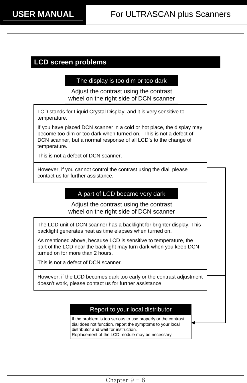
![Hanatech Co., Ltd. Chapter 5 Chapter 9 - 7 LCD screen problemsPress the [Backlight] buttonWhen you press the [Backlight] button marked [ ], the backlight must be turned-on with a faint ticking sound.Please contact your local distributor for further assistance if the key doesn’t workBacklight doesn’t turn onReport to your local disributorYour local distributor must check the firm connection of the LCD module power wire to the main board, which requires opening the head unit. Or the replacement of the LCD module may be necessary, too.Report the symptoms to your local distributor and wait for the instruction.](https://usermanual.wiki/Hanatech/ULTRASCAN/User-Guide-515797-Page-75.png)
![USER MANUAL For ULTRASCAN plus Scanners Chapter 9 - 10 This error message is saying that the cartridge’s software is very old and has never been updated for a long time.Since it is too out-dated, simply updating the base program is not enough. Your local distributor needs to collect all the cartridges from you, and update them to the latest version.“This card needs scope upgrade” ErrorWhen an error message appears as below as soon as turning on the head unit.THIS CARD NEEDS SCOPEUPGRADE. PRESS [ENTER]AND CONTINUE UPGRADEUpdate all the cartridgesLet your local distributor collect and check all the cartridges you have. Formatting the cards and rewriting software will be necessary.](https://usermanual.wiki/Hanatech/ULTRASCAN/User-Guide-515797-Page-78.png)
![Hanatech Co., Ltd. Chapter 5 Chapter 9 - 11 Update internal ROM memoryThese errors occur when the software version and internal ROM memory version do not accord.You need to update the ROM memory. Actually this is not an error, but just telling you that the internal memory needs to be updated.“Card Rom Version is different” ErrorWhen the following error message appears as soon as turning the head unit on.CARD ROM VERSIONIS DIFFERENTDO YOU WANT RELOAD?Press [YES] keyReplace with the other cartridgesTurn power off when replacing the cartridgesNo such an error any more Same error occurs again with the other cartridge(s)Discuss with your local distributor about the symptoms, and send all the cartridges to your local distributor and update them to the latest version.](https://usermanual.wiki/Hanatech/ULTRASCAN/User-Guide-515797-Page-79.png)