Hanchett Entry Systems IC0020 iClass RFID Reader User Manual FCC Part 15
Hanchett Entry Systems, Inc. iClass RFID Reader FCC Part 15
UserManual.wiki
>
Hanchett Entry Systems
>
IC0020 User Manual
Manual
Navigation menu
Upload a User Manual
Namespaces
Wiki Guide
HTML
PDF
Info
Views
User Manual
Discussion / Help
Navigation
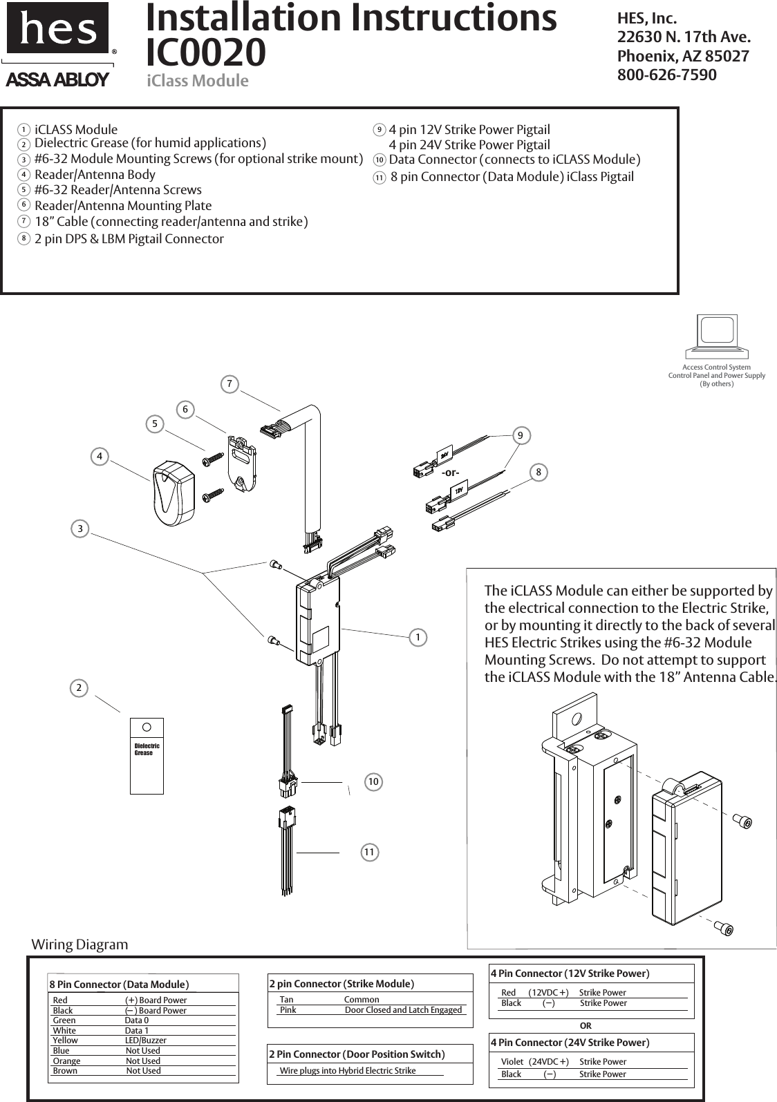
![IC0020: iClass ModuleInstallation Directions1. Prepare door jamb for the Electric Strike per the appropriatetemplate provided with the electric strike. 2. Drill a 3/4” diameter hole for Reader/Antenna install per the image below The Reader/Antenna may be positioned as desired, within the limits of the 18”cable connected to the iCLASS Module. 4. Drill a 3/8” hole for the door position switch (DPS) as required.3. The iCLASS Module can be mounted directly to the back of the several HES Electric Strikes, or supported in the frame by its electrical connection to the Electric Strike. Do not attempt to support the iCLASS Module with the 18” Antenna Cable. To attach the iCLASS Module to the Electric Strike, see page 1. Prepare Frame and Strike10. Install the Electric Strike unit in jamb cutout.11. When power is supplied, the LED will turn red, while the beeperbeeps 3 times. This sequence indicated the micro-controller isoperating properly.1. Present an iCLASS ID card to the Reader/Antenna. The LED will turn green, while the beeper beeps once. This indicatesthat the card was read successfully. Simultaneously, the keeper will click open. This indicates that communicationbetween the control panel and the Electric Strike isoperational. Testing and OperationConnect Components and WiringWire Gauge Diagram12VDC 100’ or less 24 Gauge26. Verify that the wires running from the control panel are ofadequate wire gauge (see Wire Gauge Diagram below). Connect the wire leads of the three pigtails provided to the control panel wiring based on the wiring diagram on page 2 and the appropriate termination at the control panel. 7. Mount the door position switch (DPS) into the frame. Route the 10” cable back to the Electric Strike and connect it to the 2 pin connector coming out of the Electric Strike. It does not matter which 2 pin connector is used. The LBM & DPS are wired in series--a ‘closed’ electrical circuit depicts a closed door and extended latchbolt into the hybrid Electric Strike.9. Attach the 8, 4 and 2 pin connectors at the Electric Strike to the equivalent pigtail connectors routed from the control panel. Dielectric grease should be applied to the pigtail electrical terminals if used in a humid environment. 8. Secure the Reader/Antenna Mounting Plate to the frameusing the #6-32 screws provided. Connect the 18” cable to the Reader/Antenna, snap the Reader/Antenna to theReader/Antenna Mounting Plate and pull the 18” cablethrough to the iCLASS Module.Distance In ft, Round Trip100’ to 200’200’ to 300’300’ to 400’400’ to 500’500’ to 600’600’ to 700’22 Gauge22 Gauge22 Gauge20 Gauge20 Gauge18 Gauge24VDC 24 Gauge24 Gauge24 Gauge22 Gauge22 Gauge22 Gauge20 Gauge5. Select the appropriate 4 Pin Strike Power Pigtail that matches system power. For 12V AC/DC or 16V AC, the pigtail marked “12 VDC” should be used. For 24V AC/DC, the pigtail marked “24 VDC” should be used. Reader/Antenna1-15/16” [33]5/8” [17]3/4” [19]©2010 HES, Inc.3075006.008 rev AWarning :Changes or modification to this device not expressly approved by HES, Inc., could void the user’s authority to operate the equipment.NOTE: This equipment has been tested and found to comply with the limits for a class [B] digital device, pursuant to Part 15 of the FCC Rules. These nable protection against harmful interference in a residential installation. This equipment generates, uses, and can radiate radio frequency energy and, if not installed and used in accordance with the instructions, may cause harmful int erference to radio guarantee that interference will not occur in a particular installation. If this equipment does cause harmful to radio or television reception, which can be determined by turning the equipment off and on, the user is encouraged to try to correct the interference by one or more of the following measures: Reorient or relocate the receiving antenna. Increase the separation between the equipment and receiver. Connect the equipment into an outlet on a circuit different from that to which the receiver is connected. Consult the dealer or an experienced radio/TV technician for helpThis class [B] digital apparatus meets all requirements of the Canadian Interference Causing Equipment Regulations. Operation is subject to the following two conditions: (1) this device may not cause harmful interference, and (2) this device must accept any inter- ference received, including interference that may cause undesired operation. Cet appareillage numérique de la classe [B] répond à toutes les exigences de l’inerférencé canadienne causant des réglements d’équipement. L’opération est sujette aux deux conditions suivantes: (1) ce dispositif l’interférence nocive, et (2) ce dispositif doit accepter n’importe quelle interférence reçue, y compris l’interférence quipeut causer l’opération peu désirée.limits are designed to provide reasocommunications. However, there is no interference peut ne pas causer DPS: 3/8” [10]](https://usermanual.wiki/Hanchett-Entry-Systems/IC0020/User-Guide-1369815-Page-3.png)