Hanchett Entry Systems K100620IA Electronic Cabinet Lock System User Manual Installation Manual
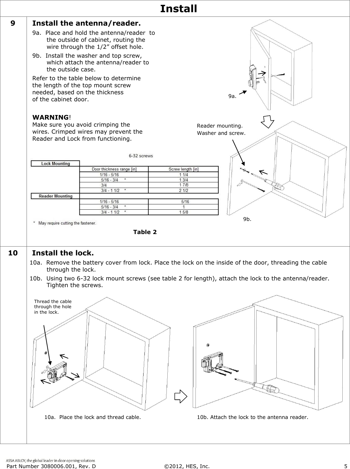
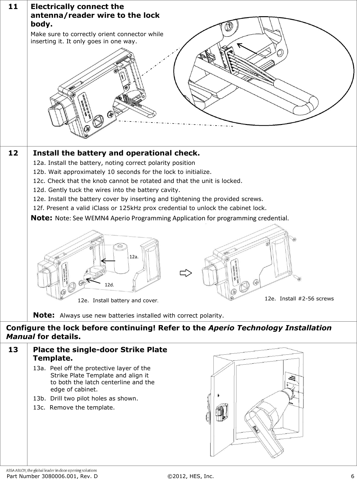
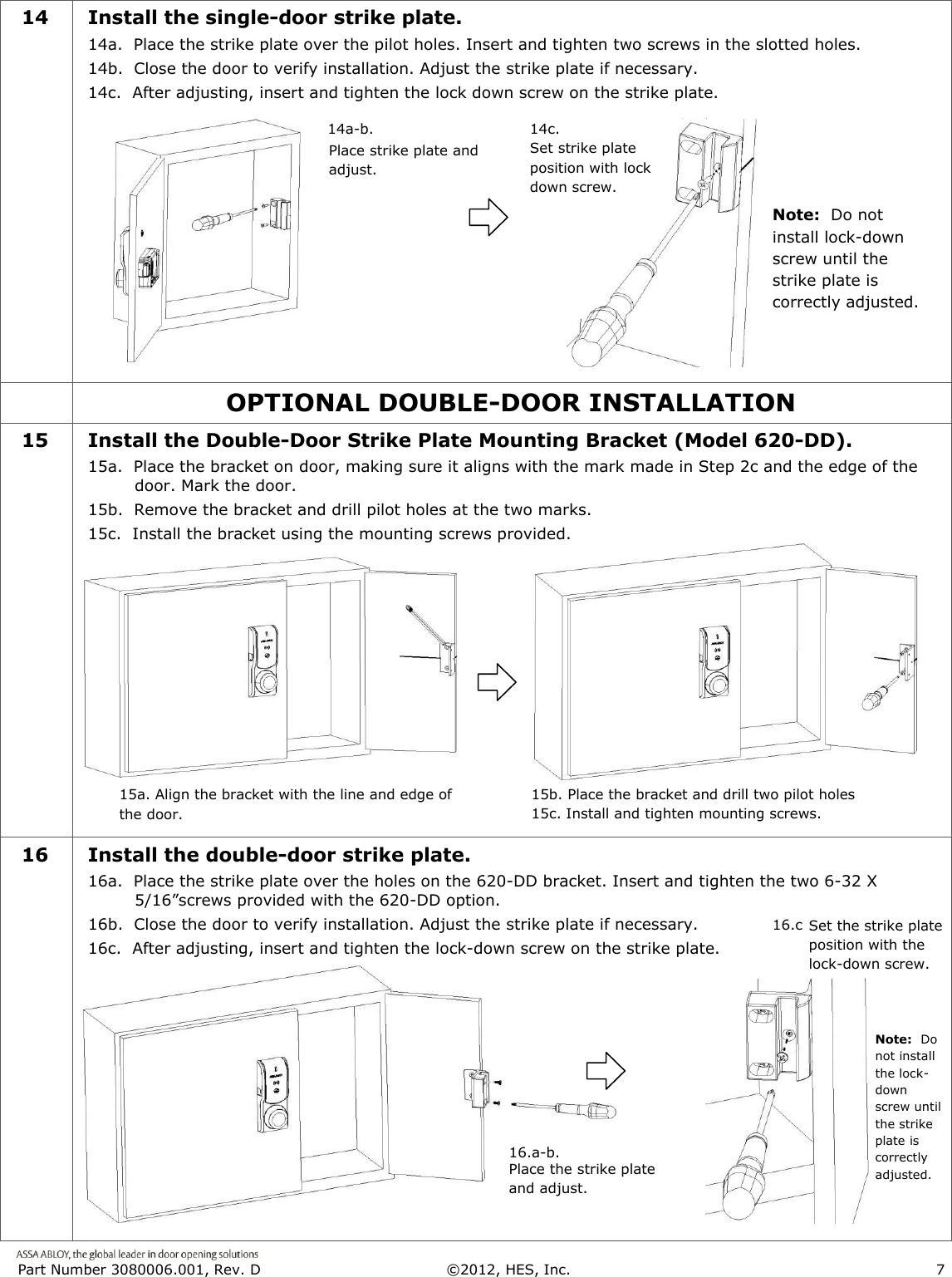
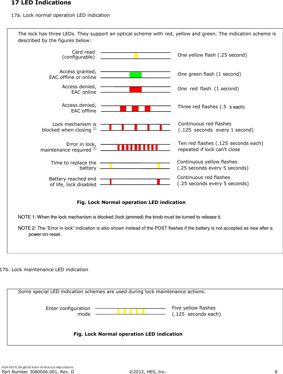
Hanchett Entry Systems, Inc. Electronic Cabinet Lock System Installation Manual
UserManual.wiki
>
Hanchett Entry Systems
>
K100620IA User Manual
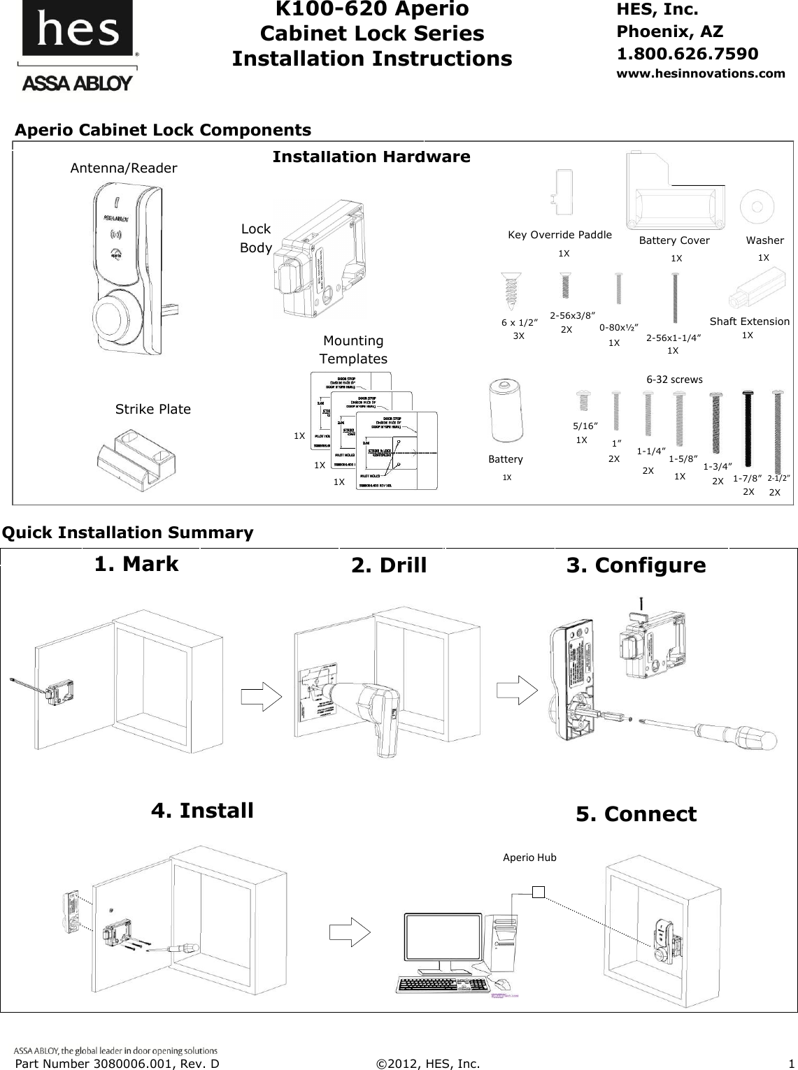
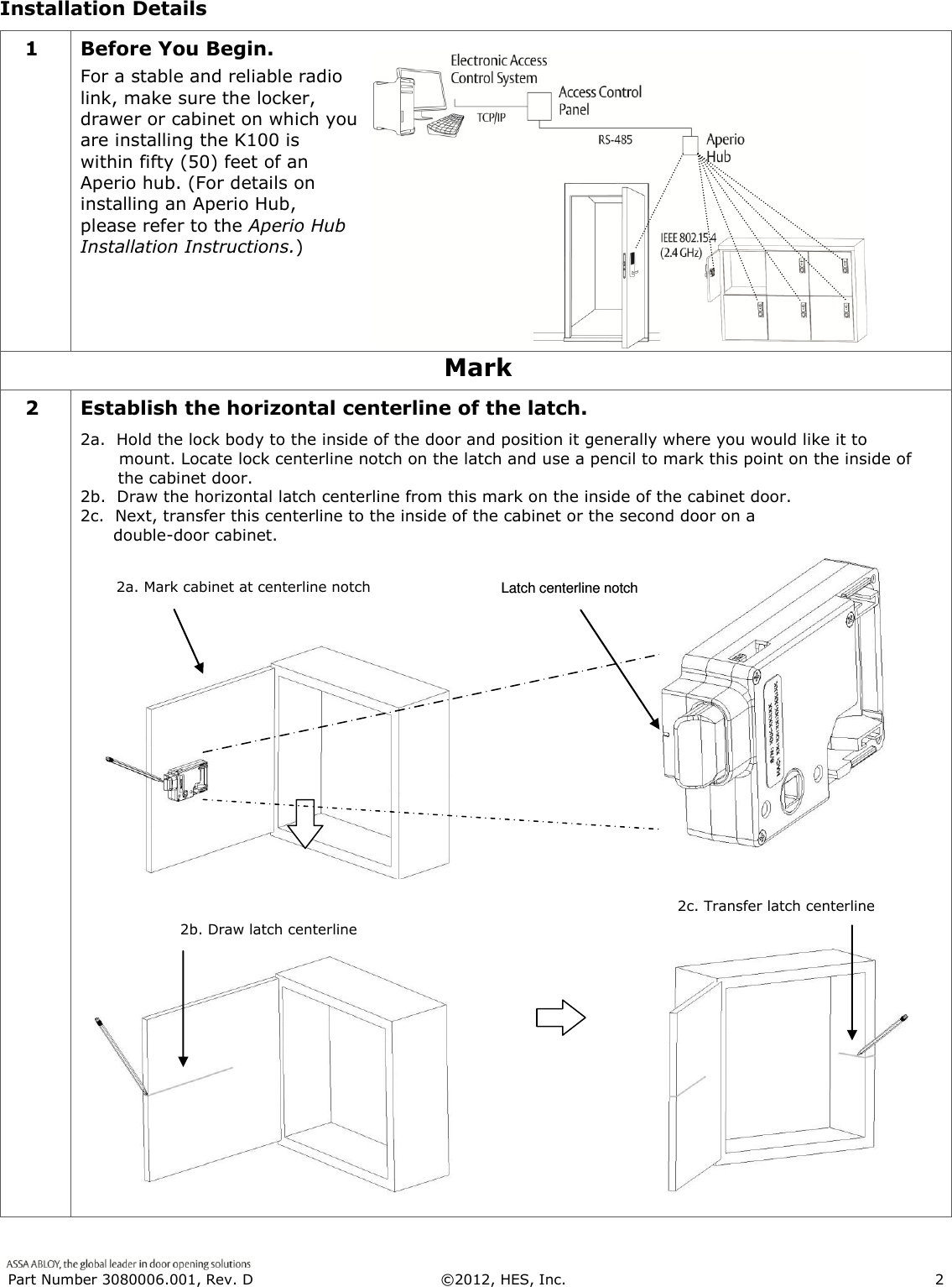
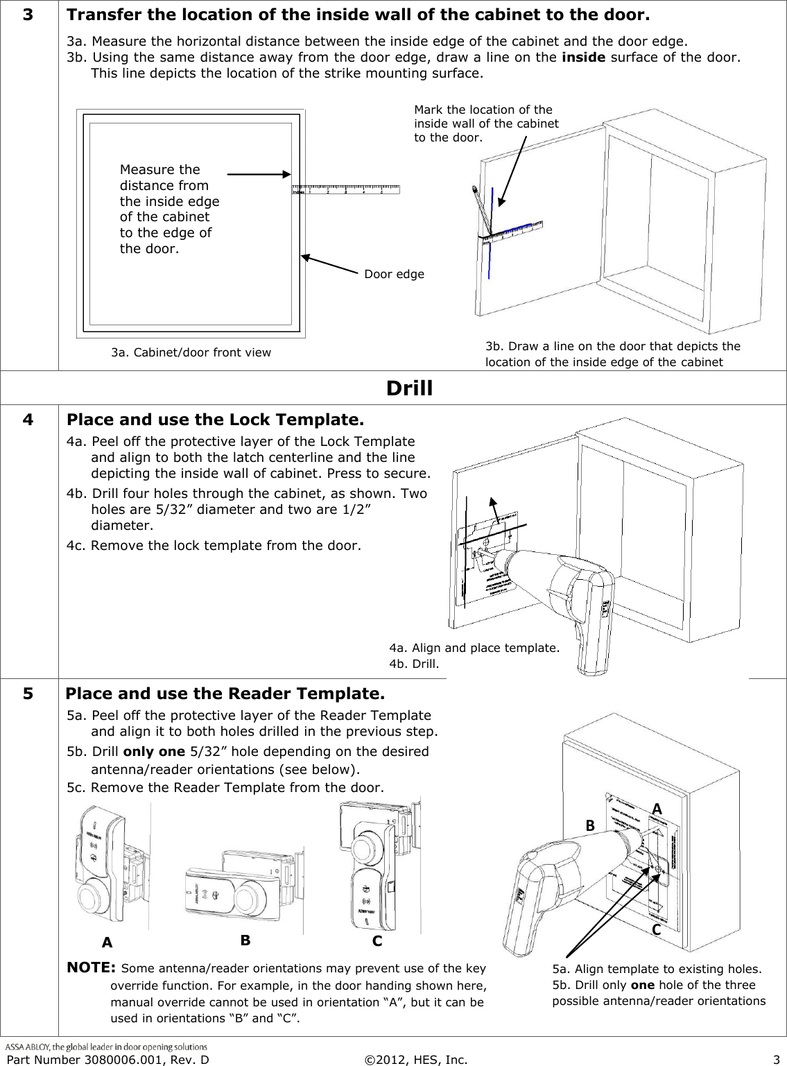
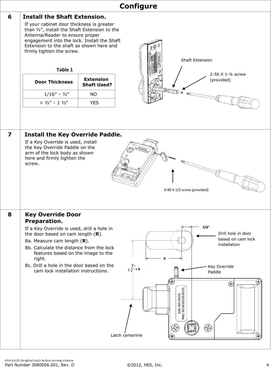
Installation Manual
Navigation menu
Upload a User Manual
Namespaces
Wiki Guide
HTML
PDF
Info
Views
User Manual
Discussion / Help
Navigation