Hanchett Entry Systems KKSR100PA Aperio Cabinet Lock (K100-622-PA2), Aperio Server Cabinet Lock (KS100-640-PA2), Aperio Reader (R100-PA2) User Manual 3080076 004 C 052215 Draft
Hanchett Entry Systems, Inc. Aperio Cabinet Lock (K100-622-PA2), Aperio Server Cabinet Lock (KS100-640-PA2), Aperio Reader (R100-PA2) 3080076 004 C 052215 Draft
Users manual
3080076.004, Rev. C 1
DRAFT
K100-622 Aperio
®
Cabinet Lock
Installation Instructions
HES, Inc.
Phoenix, AZ
1.800.626.7590
www.hesinnovations.com
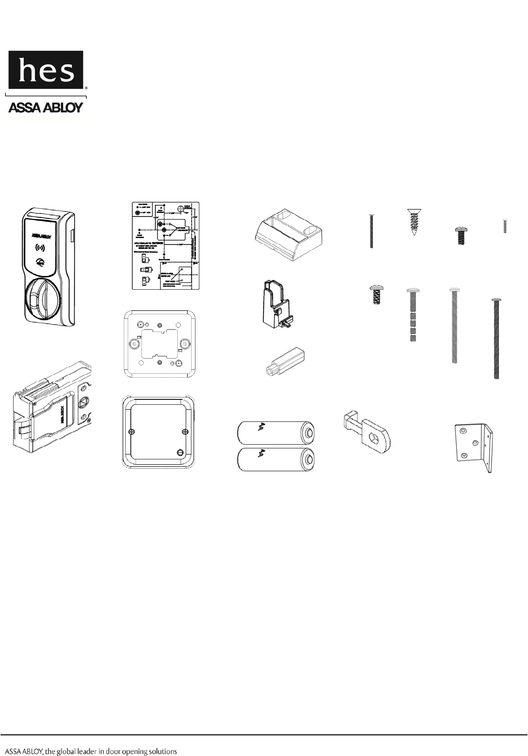
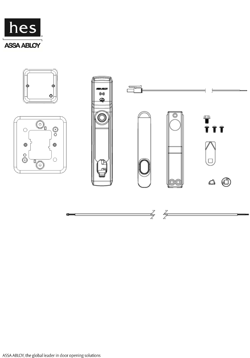
Package Contents
NOTE: The wireless hub and hub bracket are included with the K100-622H model.
Recommended Tools
Optional Additional Tools:
Gang box to mount hub
Cam Lock for Key Override
Drill, Drill bits: 1/16” [1.59 mm],
3/16” [4.76 mm], 1/2” [12.70 mm]
Approved iCLASS or Prox ID
credential.
Flathead drivers 3/32” [2.38 mm],
3/16” [4.76 mm], Phillips drivers
(P0, P2), Pencil, Wire Stripper,
Level, Square, Pliers
Wireless Frequency: 2.4 GHz, IEEE 802.15.4, using AES 128-bit encryption
Hub Power Requirement: 8–24 Volts Direct Current (VDC), 250 milliamps (mA)
Lock Battery Type: Lithium AA Cell, 1.5 Volts (V) (Energizer L91 Ultimate Lithium)
Battery Life: 50,000 cycles
Operating Temperature: 32 °F to 122 °F [0 °C to 50 °C]
Compliance: FCC Part 15, Class B, Industry Canada
Credentials Supported: Type: Proximity iCLASS
Frequency: 125 kHz 13.56 MHz
Model Identifier: K100-622-PA2 K100-622-SE2
FCC Identification: VC3-KKSR100PA VC3-KKSR100SE
IC Identification: 7160A-KKSR100622PA 7160A-KKSR100622SE
Product Specifications
Strike Plate
Shaft Extension
Energizer L91 Ultimate
Lithium Batteries
2X
Double door bracket
Lock Body
8-32 x 1 3/4”
[4.00 mm x 44.45 mm]
Breakaway
3X 8-32 x 2 1/2”
[4.00 mm x 63.50 mm]
2X 8-32 x 2 3/4”
[4.00 mm x 69.85 mm]
2X
6-32 x 5/16”
[3.5 mm x 7.94 mm]
3X
2-56 x 7/16”
[M1.4 x 0.3 x 11.11 mm]
2X
Key Override
Cam
Key Override Paddle
Template Screws
Reader
8-32 x 5/16”
[4.00 mm x 7.94 mm]
1X
Hub Bracket
Wireless Hub
In [mm]
2-56 x 1-1/4”
[M1.4 x 0.3 x 31.50 mm]
1X
6 x 1/2”
[3.50 mm x 12 mm]
5X
3080076.004, Rev. C 2
DRAFT
System Overview
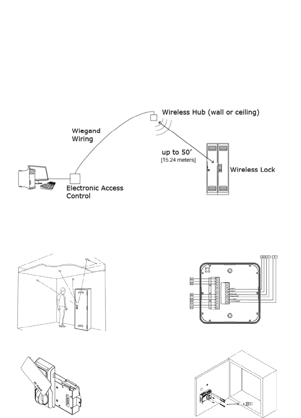
The K100-622 series wireless cabinet lock provides access control to a cabinet or drawer without the complexity and
expense of running wires to the cabinet or drawer. The K100-622 series lock connects to an access control through
a communication hub (included with the K100-622H). The communication hub connects to the access control
system with Wiegand wiring typical of a Wiegand Reader.
When a credential card is presented to the reader on the lock the request for access is sent wirelessly to the
communication hub. The communication hub then communicates through Wiegand wiring to the access control
system where the decision is made to grant or deny access.
Installation Process
Testing the Lock
Connecting the Hub
(K100-622H only)
Mounting the Lock
Locating and Mounting the Hub
(K100-622H only)
3080076.004, Rev. C 3
DRAFT
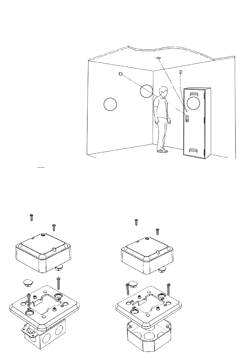
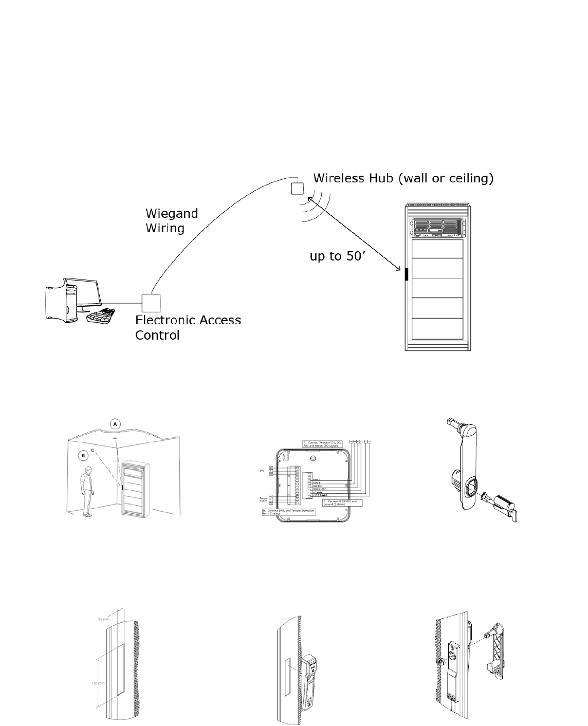
Choosing the hub location
NOTE: The following applies primarily
to the K100-622H Model with
included hub.
It is recommended that the hub be
mounted near the top of a wall, on the
ceiling or above the ceiling to reduce
potential for interference, and be facing
toward the lock for best performance.
For a stable and reliable radio link, it is
recommended that the hub is located
within 50 feet [15.24 meters] of the
lock. A maximum of two interior walls
between the hub and lock is
recommended
Recommended locations:
A: Wall Mount
B: Ceiling Mount
C: Wall Mount, Adjacent Room
NOTE: The hub is not rated for use in
plenum air spaces.
Mounting the Hub
NOTE: The following applies primarily to the K100-622H Model with included hub.
The included adapter plate can be used to mount the hub on a single or double gang box.
A
B
C
3080076.004, Rev. C 4
DRAFT
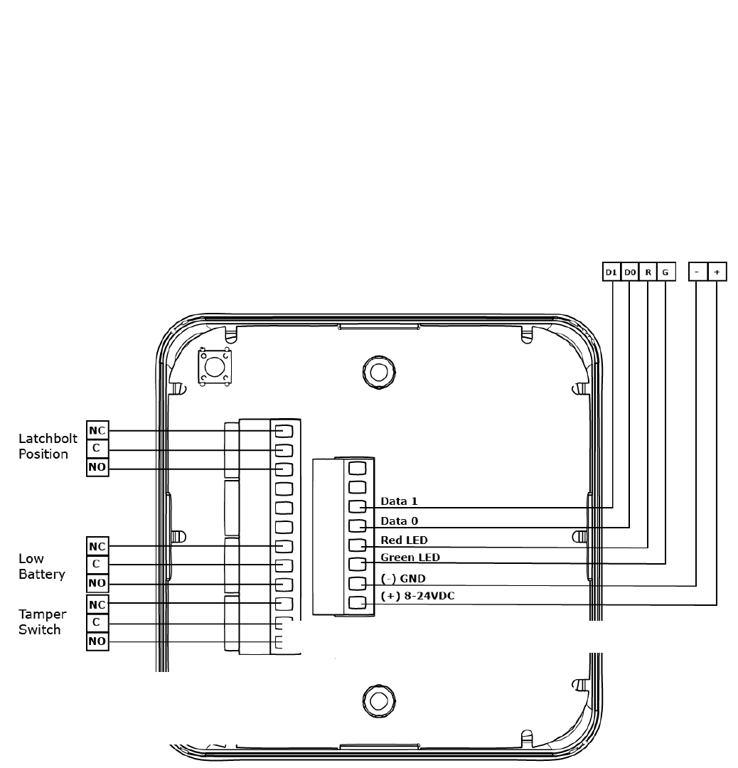
Connecting the Hub
NOTE: The following applies primarily to the K100-622H Model with included hub.
The Aperio® Hub connects to the Access Control system via Wiegand wiring. The hub requires 8–24 VDC power
(250mA). The hub includes three Form C relays that can be used to transmit latch bolt position status, low
battery signal, and a tamper signal. The hub connects to the cabinet lock wirelessly.
NOTE 1: The Green LED input is used to grant access to the cabinet lock. If the Green LED signal is not available
to indicate approved access, the approval input can be activated by a relay with “NO” attached to Green
LED and “C” to GND.
NOTE 2: The Red LED input is used to indicate access denied. If the RED LED signal is not connected, the lock will
flash RED three times when a non-approved card is presented indicating loss of connection to the hub
rather than access denied. Any other codes may be reference on the LED reference card.
1. CONNECTtheWiegandD1,D0,redandgreenLEDsignals.
3. CONNECTLatchboltPosition,Low
Battery,andTamperSwitchDetection
FormCrelays.
2. CONNECT8–24VDCandground(250mA).
3080076.004, Rev. C 5
DRAFT
Testing the Lock with the Access Control System
NOTE: With the hub connected to power and the access control system, the lock is tested with a known good
credential to confirm it will open as desired when installed.
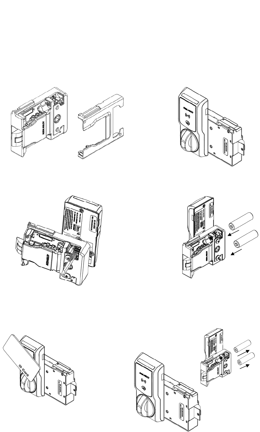
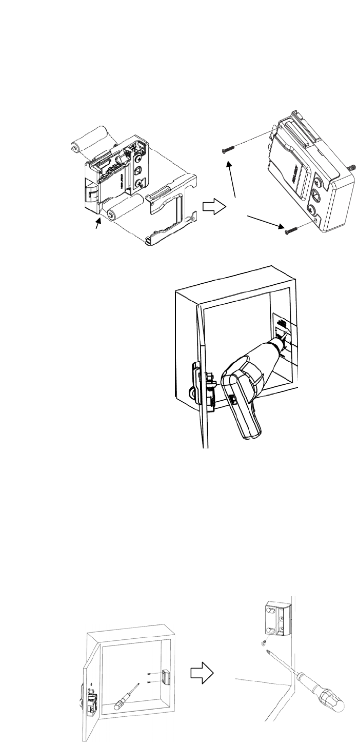
1. REMOVE the battery cover from the
lock body. 2. PASS the wire and shaft from the
reader through the lock body.
3. CONNECT the wire (the wire is
keyed) from the reader to the
socket in the lock battery
compartment.
4. INSTALL the batteries and ENSURE
correct orientation; the lock will self
test and beep once.
5. PRESENT a
credential known
to the access
control system.
6. IF a green LED, indicating
access is granted, is lit;
THEN TWIST the knob to
retract the latch.
7. REFER to the LED
reference card for any
other codes.
8. REMOVE the batteries, UNPLUG
the cable carefully, and
SEPARATE the lock and reader
to prepare for installation.
3080076.004, Rev. C 6
DRAFT
***CAUTION***
The Installer must ensure the lock can be opened before closing the cabinet at the end of these
installation instructions.
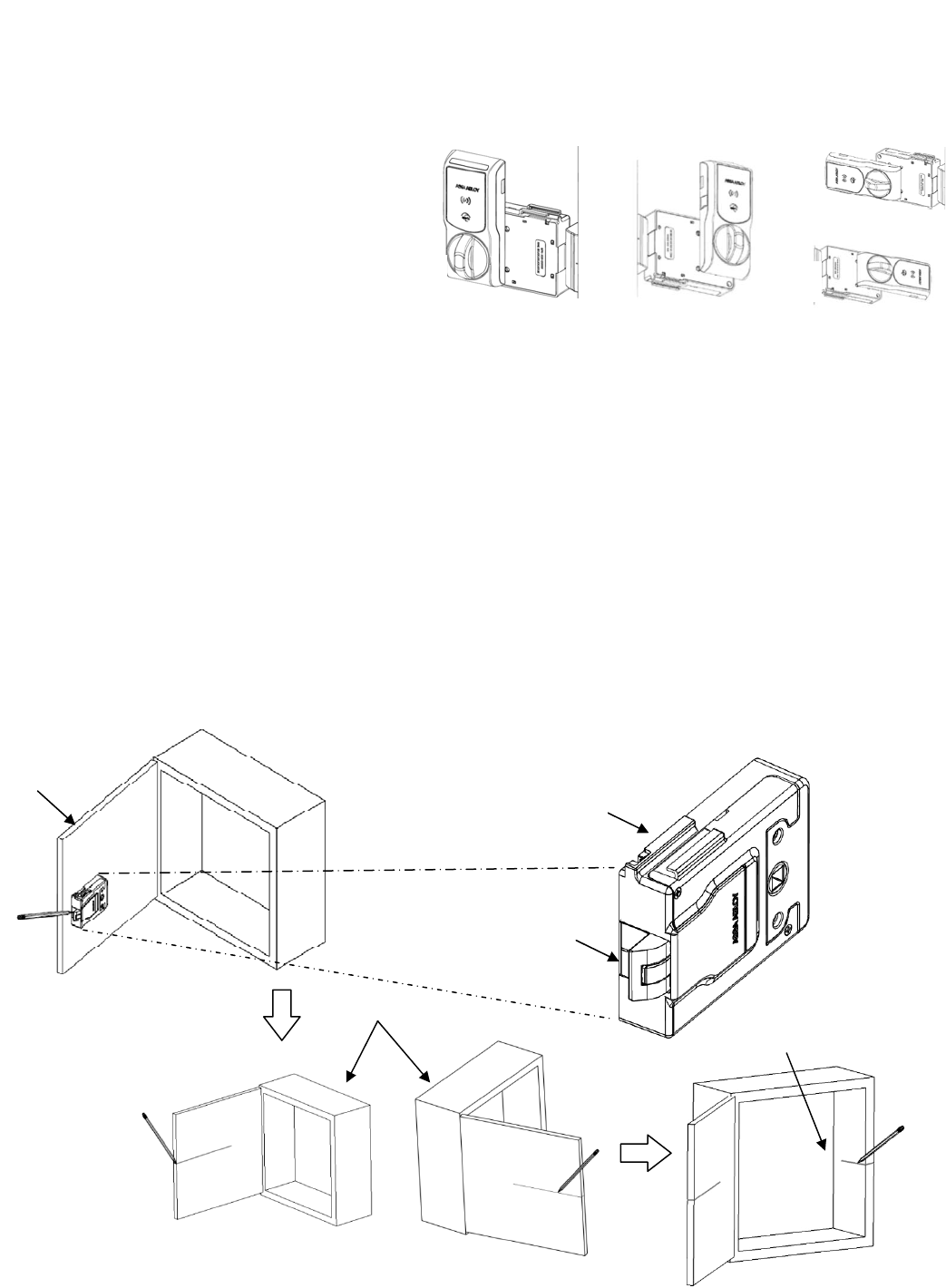
Mounting the Lock
NOTE: The K100-622 reader and lock body can be
oriented in several ways to accommodate
various cabinets and drawers.
1. ESTABLISH the horizontal centerline of the latch.
1a. HOLD the lock body to the inside of the door and POSITION it generally where
you would like it to mount.
1b. LOCATE the lock centerline notch on the latch and MARK this point on the inside
of the cabinet door using a pencil.
1c. DRAW the horizontal latch centerline from this mark on the inside of the cabinet
door and TRANSFER it to the outside of the cabinet door.
1d. TRANSFER this centerline to the inside of the cabinet or the second door on a
double-door cabinet.
1e. RECORD the MAC identification number for transfer to Aperio software.
1b
1c
1a
Latch centerline notch
A
B
C
MAC identification
number on back side
D
3080076.004, Rev. C 7
DRAFT
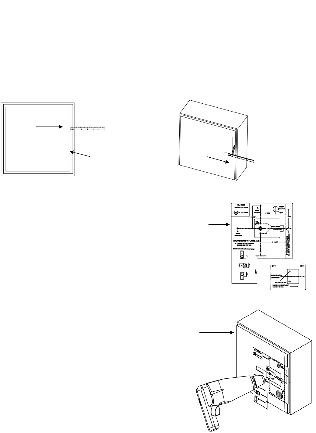
2. TRANSFER the location of the inside wall of the cabinet to the door.
2a. MEASURE the horizontal distance between the inside edge of the cabinet and the door edge.
NOTE: The drawn line depicts the location of the strike mounting surface.
2b. DRAW a line on the outside surface of the door, using the same distance away from the door edge.
3. PLACE and USE the Lock/Reader Template.
NOTE: Orientation will be reversed for a right hand door.
3a. CUT through line to separate the Strike Plate Template.
3b. PEEL OFF the protective layer of the Lock Template, ALIGN it to both the latch
centerline and the line depicting the inside wall of cabinet, and PRESS to
secure.
NOTE: Two of the holes in the following step are 3/16” [4.76 mm] diameter and two are
1/2” [12.70 mm] diameter. The two pilot holes are 1/16” [1.59 mm].
3c. DRILL four holes and two pilot holes through the cabinet, as shown
in the figure below.
3d. DRILL only one 3/16” [4.76 mm] hole depending on the desired
Antenna/Reader orientation.
3e. IF the optional key override will be installed,
THEN GO TO Step 5.
3f. REMOVE the lock template from the door.
Cab
in
et/doo
r fr
o
n
t
vi
e
w
Door edge
2a
2b
3a
3b, 3c, 3d
3080076.004, Rev. C 8
DRAFT
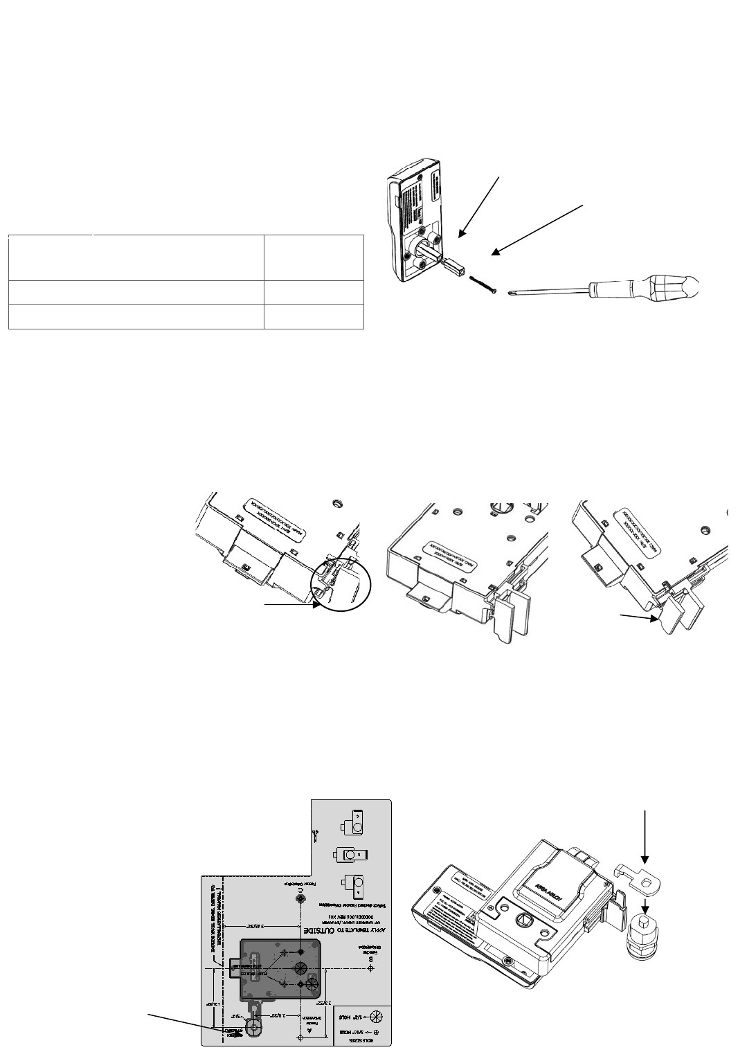
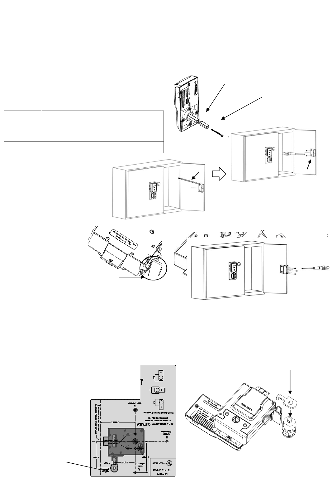
4. INSTALL the Shaft Extension.
4a. IF the cabinet door thickness is greater than ½” [12.70 mm],
THEN INSTALL the Shaft Extension to the Antenna/Reader to ensure proper engagement into the lock.
4b. INSTALL the Shaft Extension to the shaft as shown
in the figure and firmly TIGHTEN the screw.
Door
Thickness Extension
Shaft Used?
1/16” [1.59 mm] – ½” [12.70 mm] No
> ½” [12.70 mm] – 1 ½” [38.10 mm] Yes
5. IF a Cam Lock Key Override will be used, AND the orientation allows for
installation, THEN INSTALL the Key Override Paddle.
5a. INSERT the Paddle’s arm into the opening shown, and ALIGN the rails of the paddle to the ones on the
lock.
5b. SLIDE the paddle
gently until it stops.
6. PREPARE the Key Override Door.
NOTE: The Cam Lock is optional and must
be obtained by others.
6a. IF a Key Override is used,
THEN USE template to mark and drill a
hole for a 3/4” [19.05 mm] Cam Lock
in the door.
Shaft Extension 2-56 X 1-¼” [M1.4 x 0.3 x 31.50 mm]
screw (provided)
Table1
5b
6a
6b. INSTALL the optional Cam Lock with
the cabinet lock as shown in the
fi
g
ure.
6b
5a

3080076.004, Rev. C 9
DRAFT
7. INSTALL the Antenna/Reader.
***CAUTION***
Pinching the wires may prevent the Reader and
Lock from properly functioning.
7a. PLACE and HOLD the antenna/reader to the outside
of cabinet, routing the wire through the
1/2” [12.70 mm] offset hole, and ENSURE the knob
is in the locked position in the vertical.
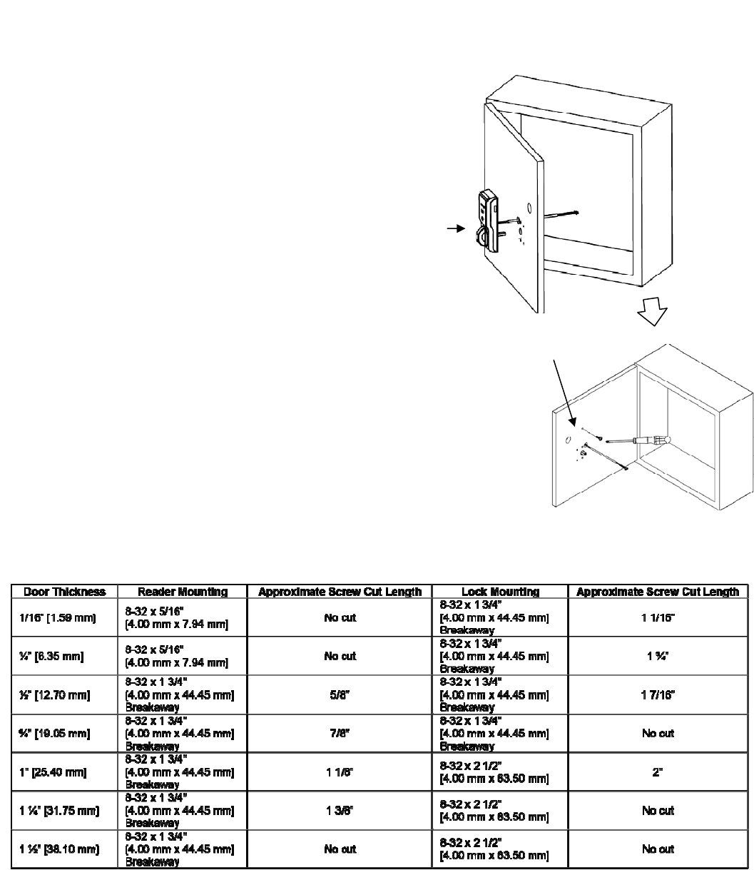
NOTE: Using the Table 2 below will help determine the
length of the top mount screw needed, based
on the thickness of the cabinet door.
7b. INSTALL the top mount screw to attach
the antenna/reader to the outside case.
Reader mounting screw.
7a
7b
Table 2

3080076.004, Rev. C 10
DRAFT
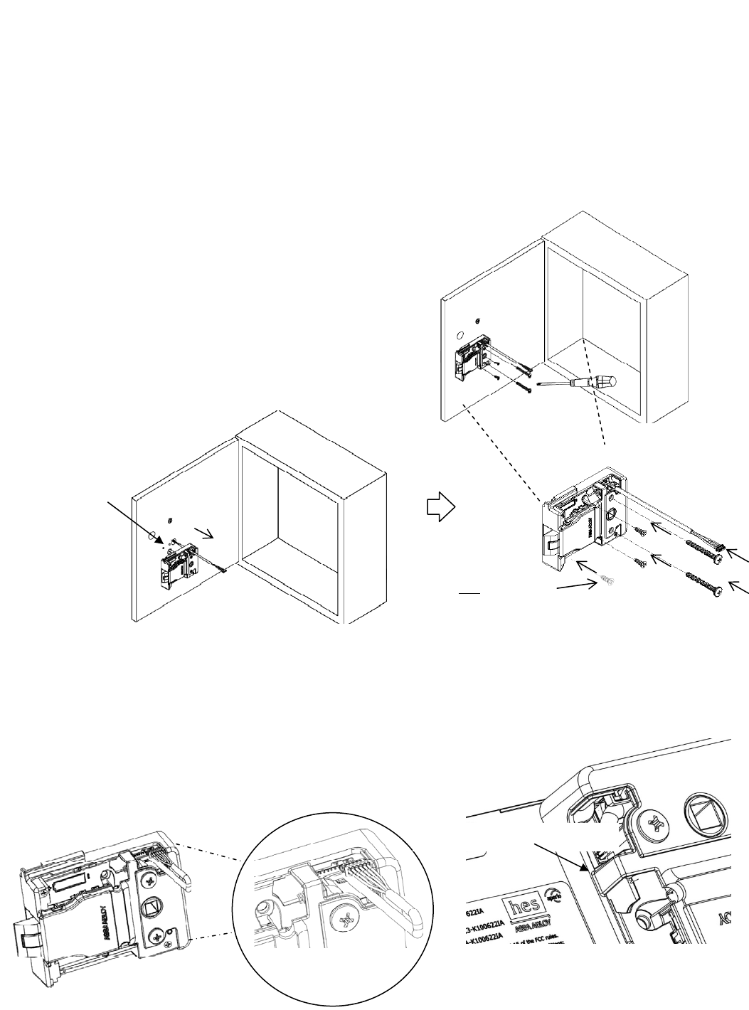
8. INSTALL the lock.
8a. REMOVE the battery cover from lock.
8b. PLACE the lock on the inside of the door, threading the cable through the lock.
8b. ATTACH the lock to the antenna/reader using two 8-32 [4.00 mm] lock mount screws
(see Table 2 for length), and TIGHTEN the screws.
8c. INSTALL the two #6 self-threading screws and TIGHTEN.
NOTE: The third #6 self-threading screw is important to
achieve maximum holding force for doors greater
than 5/8” [15.88 mm] thick.
8d. INSTALL the third #6 self-threading screw only if the door
is more than 5/8” [15.88 mm] thick, using the lock as a
guide, and TIGHTEN.
9. Electrically CONNECT the antenna/reader wire to the lock body.
NOTE: The antenna/reader wire connector is keyed to only fit one way.
9a. ENSURE correct orientation of the connector while inserting it.
9b. TUCK excess cable into lock body as shown.
9a 9b
Connector cable tucked in
Cable is threaded
through the hole
in the lock.
8a
Used only
for doors less
than 5/8” thick.
8
b
8c
8d
3080076.004, Rev. C 11
DRAFT
10. INSTALL the Batteries.
NOTE: New batteries should always be used and inserted in the
correct polarity position.
10a. INSTALL the battery and battery cover.
10b. INSTALL and TIGHTEN the screws.
11. PLACE the single-door Strike Plate Template.
11a. PEEL OFF the protective layer of the Strike Plate Template
and ALIGN it to both the latch centerline and the edge of
cabinet.
11b. DRILL two pilot holes as shown on template.
11c. REMOVE the template.
***CAUTION***
The Installer must ensure the lock can be opened before closing the cabinet.
12. INSTALL the single-door strike plate.
12a. PLACE the strike plate over the pilot holes, and INSERT and TIGHTEN the two screws in the slotted holes.
12b. CLOSE the door to verify installation, and ADJUST the strike plate if necessary.
12d. INSERT and TIGHTEN the lock down screw on the strike plate.
10a
10b
12a–c
12d
3080076.004, Rev. C 12
DRAFT
OPTIONAL DOUBLE-DOOR INSTALLATION
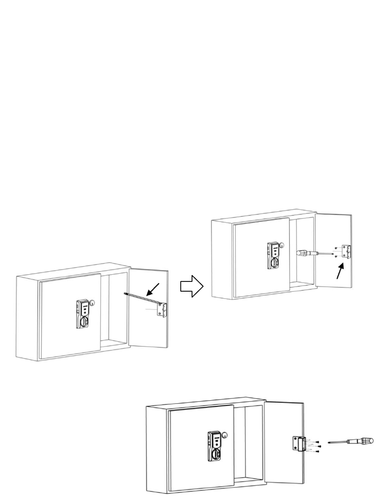
13. INSTALL the Double-Door Strike Plate Mounting Bracket
NOTE: The double-door bracket requires that one door can be secured.
13a. PLACE the bracket on door, making sure it aligns with the mark made in Step 2c and the edge of the door.
13b. MARK the door.
13c. REMOVE the bracket and DRILL pilot holes at the two marks.
13d. INSTALL the bracket using the mounting screws provided.
14. INSTALL the double-door strike plate.
14a. PLACE the strike plate over the holes on the bracket.
14b. INSERT and TIGHTEN the three 6-32 X 5/16”screws
provided.
4. INSTALL the Shaft Extension.
4a. IF the cabinet door thickness is greater than ½” [12.70 mm],
THEN INSTALL the Shaft Extension to the Antenna/Reader to ensure proper engagement into the lock.
4b. INSTALL the Shaft Extension to the shaft as shown
in the figure and firmly TIGHTEN the screw.
Door
Thickness Extension
Shaft Used?
1/16” [1.59 mm] – ½” [12.70 mm] No
> ½” [12.70 mm] – 1 ½” [38.10 mm] Yes
5. IF a Cam Lock Key Override will be used, AND the orientation allows for
installation, THEN INSTALL the Key Override Paddle.
5a. INSERT the Paddle’s arm into the opening shown, and ALIGN the rails of the paddle to the ones on the
lock.
5b. SLIDE the paddle
gently until it stops.
6. PREPARE the Key Override Door.
NOTE: The Cam Lock is optional and must
be obtained by others.
6a. IF a Key Override is used,
THEN USE template to mark and drill a
hole for a 3/4” [19.05 mm] Cam Lock
in the door.
Shaft Extension 2-56 X 1-¼” [M1.4 x 0.3 x 31.50 mm]
screw (provided)
Table1
13a
13b and 13c
5b
6a
6b. INSTALL the optional Cam Lock with
the cabinet lock as shown in the
fi
g
ure.
6b
5a
3080076.004, Rev. C 13
DRAFT
7. INSTALL the Antenna/Reader.
***CAUTION***
Pinching the wires may prevent the Reader and
Lock from properly functioning.
7a. PLACE and HOLD the antenna/reader to the outside
of cabinet, routing the wire through the
1/2” [12.70 mm] offset hole, and ENSURE the knob
is in the locked position in the vertical.
NOTE: Using the Table 2 below will help determine the
length of the top mount screw needed, based
on the thickness of the cabinet door.
7b. INSTALL the top mount screw to attach
the antenna/reader to the outside case.
Reader mounting screw.
7a
7b
Table 2
3080076.004, Rev. C 14
DRAFT
8. INSTALL the lock.
8a. REMOVE the battery cover from lock.
8b. PLACE the lock on the inside of the door, threading the cable through the lock.
8b. ATTACH the lock to the antenna/reader using two 8-32 [4.00 mm] lock mount screws
(see Table 2 for length), and TIGHTEN the screws.
8c. INSTALL the two #6 self-threading screws and TIGHTEN.
NOTE: The third #6 self-threading screw is important to
achieve maximum holding force for doors greater
than 5/8” [15.88 mm] thick.
8d. INSTALL the third #6 self-threading screw only if the door
is more than 5/8” [15.88 mm] thick, using the lock as a
guide, and TIGHTEN.
9. Electrically CONNECT the antenna/reader wire to the lock body.
NOTE: The antenna/reader wire connector is keyed to only fit one way.
9a. ENSURE correct orientation of the connector while inserting it.
9b. TUCK excess cable into lock body as shown.
9a 9b
Connector cable tucked in
Cable is threaded
through the hole
in the lock.
8a
Used only
for doors less
than 5/8” thick.
8
b
8c
8d

3080076.004, Rev. C 15
DRAFT
10. INSTALL the Batteries.
NOTE: New batteries should always be used and inserted in the
correct polarity position.
10a. INSTALL the battery and battery cover.
10b. INSTALL and TIGHTEN the screws.
11. PLACE the single-door Strike Plate Template.
11a. PEEL OFF the protective layer of the Strike Plate Template
and ALIGN it to both the latch centerline and the edge of
cabinet.
11b. DRILL two pilot holes as shown on template.
11c. REMOVE the template.
***CAUTION***
The Installer must ensure the lock can be opened before closing the cabinet.
12. INSTALL the single-door strike plate.
12a. PLACE the strike plate over the pilot holes, and INSERT and TIGHTEN the two screws in the slotted holes.
12b. CLOSE the door to verify installation, and ADJUST the strike plate if necessary.
12d. INSERT and TIGHTEN the lock down screw on the strike plate.
10a
10b
12a–c
12d
3080076.004, Rev. C 16
DRAFT
OPTIONAL DOUBLE-DOOR INSTALLATION
13. INSTALL the Double-Door Strike Plate Mounting Bracket
NOTE: The double-door bracket requires that one door can be secured.
13a. PLACE the bracket on door, making sure it aligns with the mark made in Step 2c and the edge of the door.
13b. MARK the door.
13c. REMOVE the bracket and DRILL pilot holes at the two marks.
13d. INSTALL the bracket using the mounting screws provided.
14. INSTALL the double-door strike plate.
14a. PLACE the strike plate over the holes on the bracket.
14b. INSERT and TIGHTEN the three 6-32 X 5/16”screws
provided.
13a
13b and 13c

3080076.004, Rev. C 17
DRAFT
WARNING
FCC Statement
This equipment has been tested and found to comply with the limits for a class B digital device, pursuant to part 15 of the FCC Rules.
These limits are designed to provide reasonable protection against harmful interference in a residential installation. This equipment
generates, uses, and can radiate radio frequency energy and if not installed and used in accordance with the instructions, may cause
harmful interference to radio communications. However, there is no guarantee that interference will not occur in a particular
installation. If this equipment does cause harmful interference to radio or television reception, which can be determined by turning
the equipment off and on, the user is encouraged to try to correct the interference by one or more of the following measures:
1. Reorient or relocate the receiving antenna.
2. Increase the separation between the equipment and receiver.
3. Connect the equipment into an outlet on a circuit different from that to which the receiver is connected.
4. Consult the dealer or an experienced radio/TV technician for help.
Operation with non-approved equipment is likely to result in interference to radio and TV reception. The user is cautioned that
changes and modifications made to the equipment without the approval of manufacturer could void the user’s authority to operate
this equipment.
IC Statement
This device complies with Industry Canada license-exempt RSS standards(s). Operation is subject to the following two conditions:
(1) This device may not cause interference, and
(2) This device must accept any interference, including interference that may cause undesired operation.
Conformité aux normes FCC
Cet équipement a été testé et trouvé conforme aux limites pour un dispositif numérique de classe B, conformément à la Partie 15
des règlements de la FCC. Ces limites sont conçues pour fournir une protection raisonnable contre les interférences nuisibles dans
une installation résidentielle. Cet équipement génère, utilise et peut émettre des fréquences radio et, s'il n'est pas installé et utilisé
conformément ment aux instructions du fabricant, peut causer des interferences nuisibles aux communications radio. Rien ne
garantit cependant que l'interférence ne se produira pas dans une installation particulière. Si cet équipement provoque des
interférences nuisibles à la réception radio ou de télévision, qui peut être déterminé en comparant et en l'éteignant, l'utilisateur est
encouragé à essayer de corriger les interférence par une ou plusieurs des mesures suivantes:
1. Réorienter ou déplacer l'antenne de réception.
2. Augmenter la distance entre l'équipement et le récepteur.
3. Branchez l'appareil dans une prise sur un circuit différent de celui auquel le récepteur est connecté.
4. Consultez votre revendeur ou un technicien radio / TV pour assistance.Avertissement
Les changements ou modififications à cet appareil sans expressément approuvée par la partie responsable de conformité pourraient
annuler l'autorité de l'utilisateur de faire fonctionner cet équipement.
Conformité aux normes IC
Cet appareil est confrome avec Industrie Canada exempt de license RSS standard(s). Son fonctionnement est souimes aux deux
conditions suivantes:
(1) cet appareil ne peut causer d’interférences, et
(2) cet appareil doit accepter toute interference, y compris des interférences qui peuvent provoquer un fonctionnement indésirable
du périphérique.
For Technical Support please call 1-800-626-7590
Part Number 3080006.009 Rev. C 1
DRAFT
KS100-640H Aperio
®
Cabinet Lock
Installation Instructions
HES, Inc.
Phoenix, AZ
1.800.626.7590
www.hesinnovations.com
Package Contents
Recommended Tools
Approved RFID Credential
Phillips P2 driver, RJ45 cable
PoE power injector (48VDC)
Optional Additional Tools:
Gang box to mount hub
SFIC Core for key override
Optional Additional Tools:
Normally Open DPS switches
Product Specifications
Wireless Frequency: 2.4 GHz, IEEE 802.15.4, using AES 128bit encryption
Hub Power Requirement: 8-24VDC, 250mA
Lock Power: 48 VDC Power over Ethernet (PoE) 802.3af compliant, or 24 VDC Power Supply
(Supply not provided)
Power Consumption: Less than 1W
Operating Temperature: -10C to 50C
Holding Force: 250 lbs
Compliance: FCC Part 15, Industry Canada, BHMA: A156.3, A156.36, A156.25
Credentials Supported:
Type: Proximity iCLASS
Frequency: 125 kHz 13.56 MHz
Model Identifier: KS100-640-PA2 KS100-640-SE2
FCC Identification: VC3-KKSR100PA VC3-KKSR100SE
IC Identification: 7160A-KKSR100640PA 7160A-KKSR100640SE
Hub Mounting
Bracket
Aperio Hub
Handling
Selector
Lock Handle
Mounting Plate
Mounting Screws
Cams (x3)
DPS Cable
SFIC
Cam
24VDCCable
Part Number 3080006.009 Rev. C 2
DRAFT
System Overview
The KS100-640 wireless server cabinet lock extends access control to a server cabinet without the complexity and
expense of running wires. The KS100-640 cabinet lock connects to an access control system through the included
communication hub. The communication hub connects to the access control system with Wiegand wiring typical
of a Wiegand reader.
When a credential card is presented to the reader on the lock, the request for access is sent wirelessly to the
communication hub. The communication hub then communicates through Wiegand wiring to the access control
system where the decision is made to grant or deny access.
Installation Steps
D. Prepare the Cabinet
A. Locate and Mount the Hub B. Connect the Hub
E. Install the Lock F. Install Handin
g
Selector
C. Install an SFIC Core
Part Number 3080006.009 Rev. C 3
DRAFT
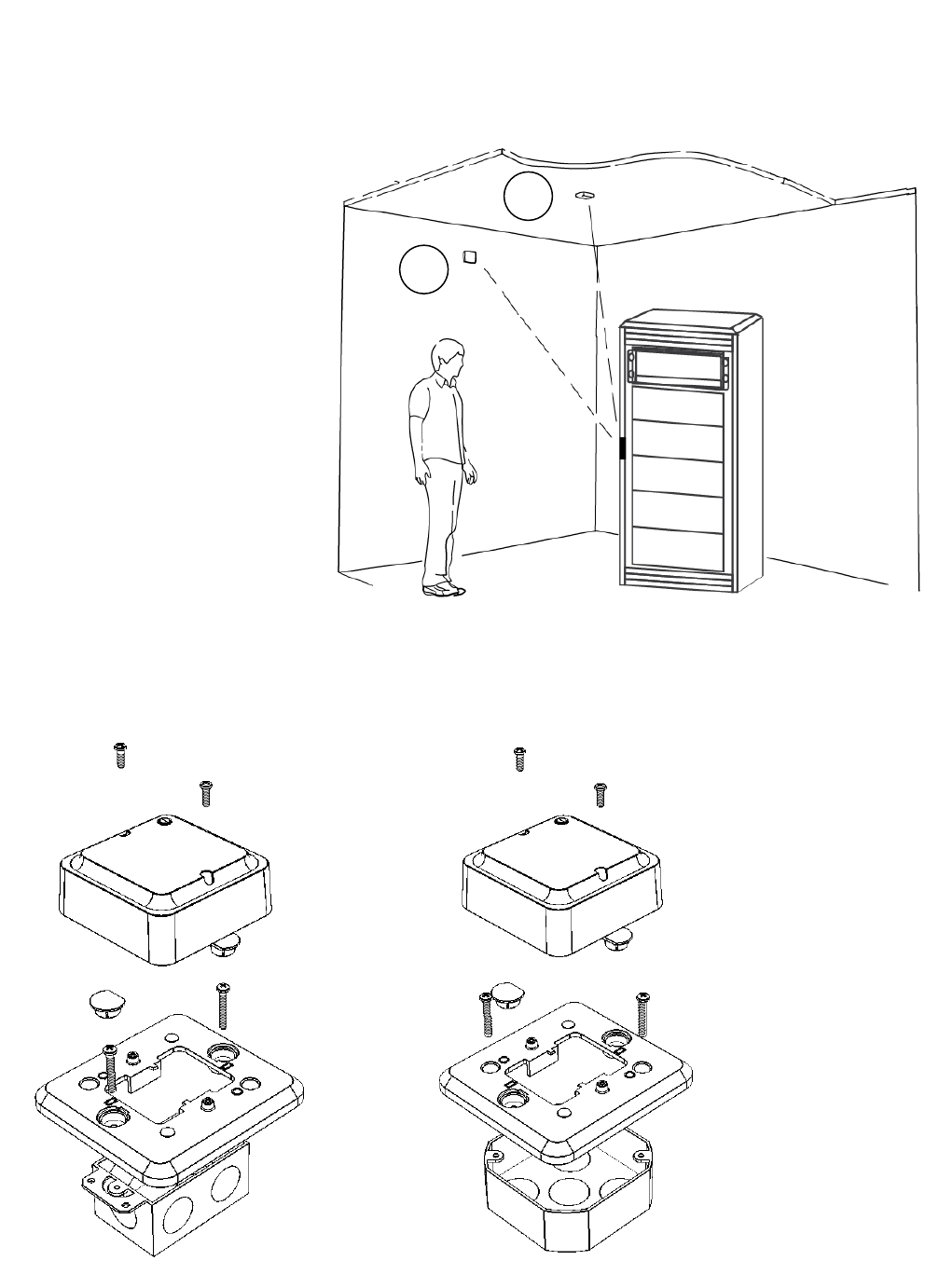
1. Locating the hub
It is recommended that the hub be mounted
on the ceiling or near the top of a wall to
reduce potential for interference. Note, the
hub is not rated for use in plenum air
spaces.
For a stable and reliable radio link, it is
recommended that the hub be located
within fifty (50) feet of the lock. A
maximum of two interior walls between
the hub and lock is recommended
Recommended locations:
A: Ceiling Mount
B: Wall Mount
2. Mounting the Hub.
The included adapter plate can be used to mount the hub on a single or double gang box.
A
B
Part Number 3080006.009 Rev. C 4
DRAFT
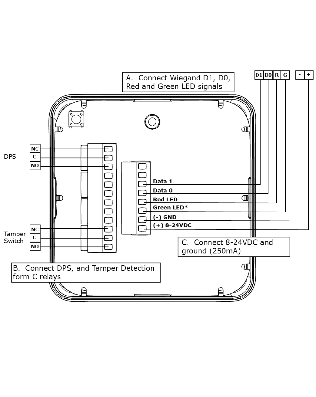
3. Wiring the Hub.
The Aperio Hub connects to the Access Control system via Wiegand wiring. The hub requires 8-24VDC power
(250mA). The hub includes two form C relays that can be used to transmit door position and tamper detection
signals. The hub connects to the cabinet lock wirelessly.
4. Installing an SFIC Core
A key override (SFIC) provides a backup entry method in the rare case the KS100 or access control system is
inactive. We recommend this option.
The included SFIC cam has been tested with Medeco and Sargent 6- or 7-pin SFIC cores.
*Note: the Green LED input is used to grant access to the
cabinet lock. If the Green LED signal is not available to
indicate approved access, the approval input can be activated
by a relay with NO attached to Green LED and COMMON to
GND.
*Note: the Red LED input is used to indicate access denied.
If the RED LED signal is not connected, the lock will flash RED
3 times when a non-approved card is presented indicating loss
of connection to the hub rather than access denied. Refer to
the LED reference card for any other codes.
*Note: the DPS signal will trigger when
either the latch handle or the door is out
of position. Both the latch handle and
door must be in position for a secure DPS
signal.
Part Number 3080006.009 Rev. C 5
DRAFT
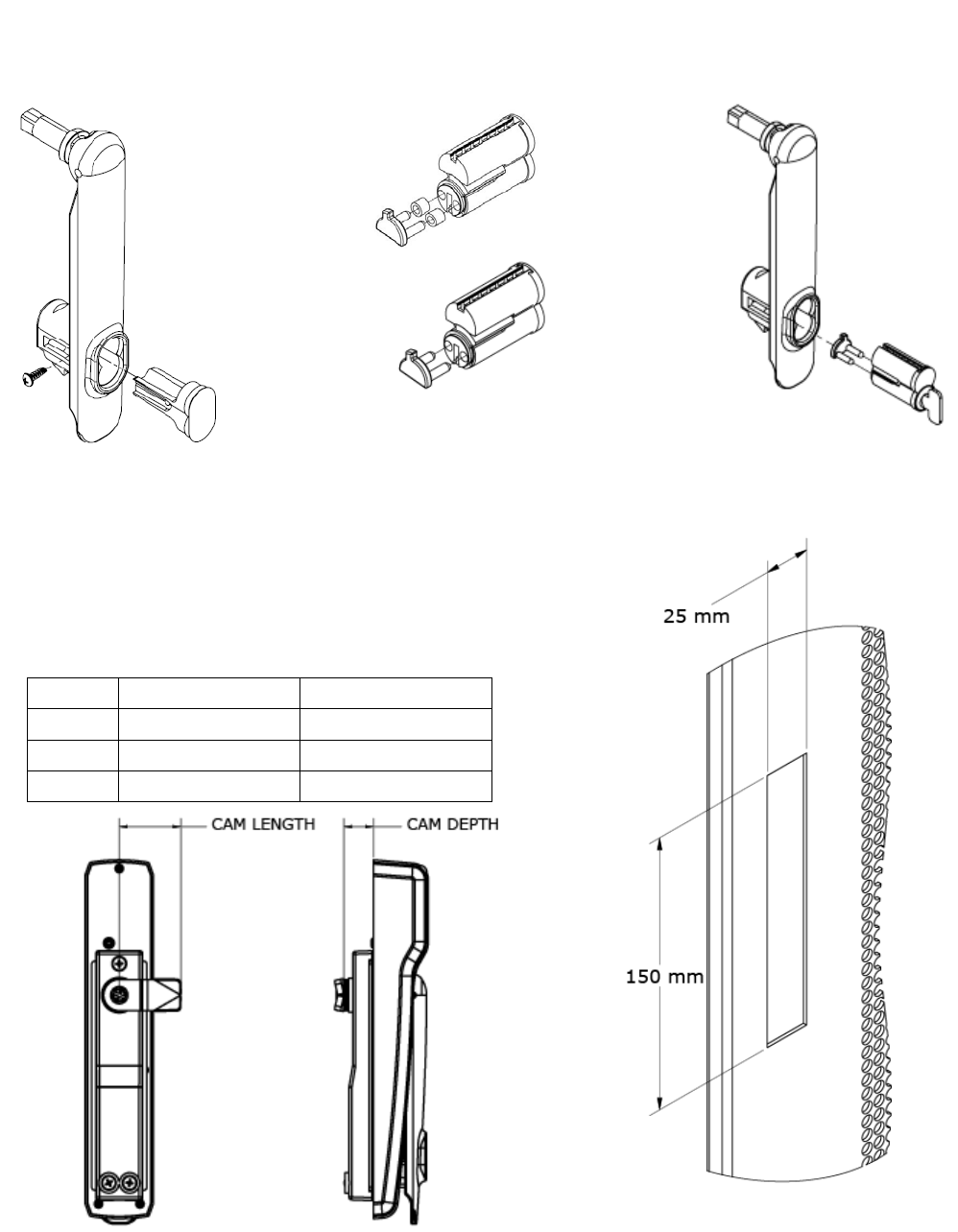
5. Preparing the Rack
LOCATE the 25mm x 150mm lock cutout on the
door, some doors may require modification.
1. VERIFY 48V POE power is available at the rack.
2. RE_USE the existing cam if possible.
3. Three cams are supplied.
CAM CAM LENGTH CAM DEPTH
CAM 1 38mm [1-1/2"] 16mm [5/8"]
CAM 2 38mm [1-1/2"] 24mm [15/16"]
CAM 3 45mm [1-3/4"] 22.5mm [7/8"]
1. REMOVE plug from handle 3. INSERT SFIC into lock
7-pin
2. INSERT cam into SFIC using the
included spacers with 6-pin SFICs.
6-pin
Part Number 3080006.009 Rev. C 6
DRAFT
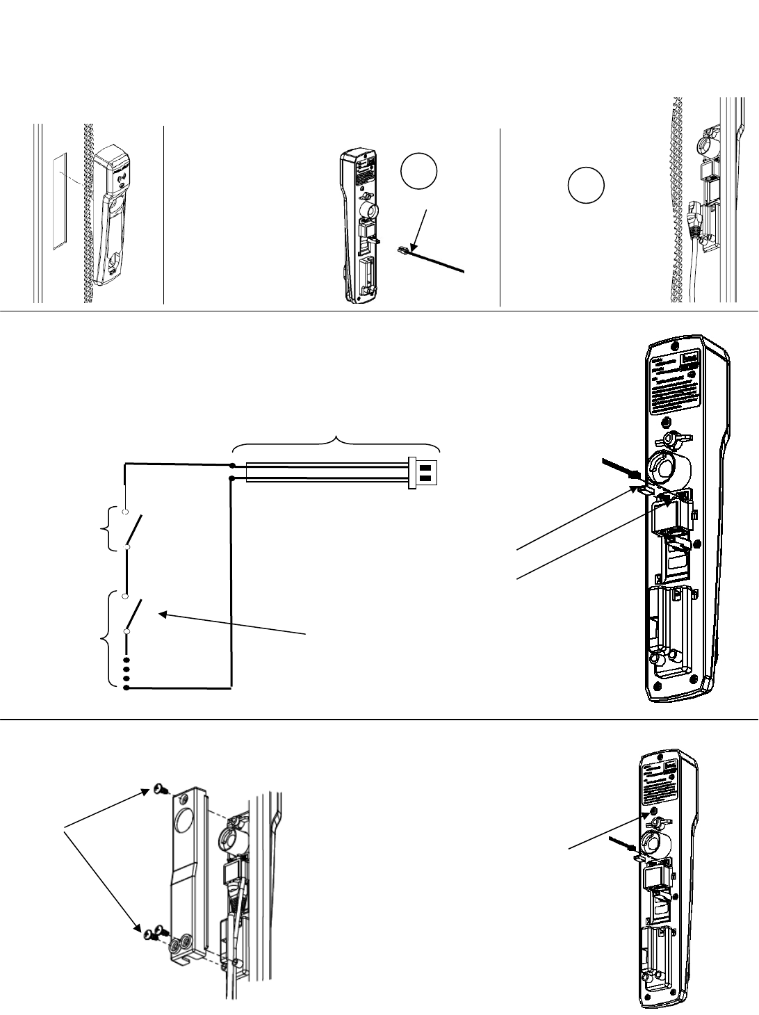
6. Installing the lock on the door
1. SLIDE lock into cutout.
PLUG 48V PoE RJ-45
cable into lock. Lock
will beep once and
perform self test.
3. Optional: The DPS signal is closed when the handle is resting in
its locked position. The DPS circuit can be extended to include
normally open DPS switches arranged in a series to monitor
additional doors and panels.
4. ATTACH rear bracket with screws.
DPS Extension Cable
DPS
Switches
(SPST-
NO): As
Needed
Switch #1
(SPST-NO):
Provided
Extending the DPS Circuit:
A: REMOVE the DPS jumper.
B: CONNECT the included DPS
extension cable
C: CONNECT additional normally
open DPS switches as shown to
monitor additional panels.
24VDC cable
A
B
5. ENSURE that the lock is fully secured
and flush to the mounting surface in
order to depress tamper switch on
back of device for correct operation.
Tamper Switch
NOTE: If the tamper switch is not
fully depressed, you will
see a flashing red light
and the device will not
read cards.
2. SELECT Power source: (A. 24VDC Supply or
B. 48V PoE)
CONNECT 24 VDC cable
to lock.
CONNECT 24 VDC power
supply (not provided) to
24 VDC cable.
Red wire (24VDC), black
wire (Ground)
Part Number 3080006.009 Rev. C 7
DRAFT
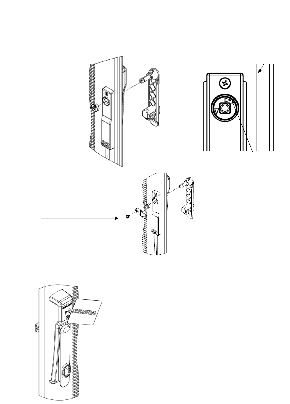
7. Installing the Handing Selector
NOTE: Be careful not to insert/snap the handle all the way in as the lever will lock.
8. Testing the Lock with the Access Control System
TEST the lock with a known good credential to confirm it will open as desired when installed.
2. POSITION the arrows to
point toward the door edge
as shown above.
1. INSERT handing
selector into lock.
Dooredge
1. PRESENT a credential known
to the access control system.
2. VERIFY a green LED is lit
indicating access is granted;
LIFT lever and TURN to open
the cabinet. REFER to the LED
reference card for any other
3. SECURE cam with screw.

Part Number 3080006.009 Rev. C 8
DRAFT
FCC Statement
This equipment has been tested and found to comply with the limits for a class B digital device, pursuant to part 15 of
the FCC Rules. These limits are designed to provide reasonable protection against harmful interference in a
residential installation. This equipment generates, uses, and can radiate radio frequency energy and if not installed
and used in accordance with the instructions, may cause harmful interference to radio communications. However,
there is no guarantee that interference will not occur in a particular installation. If this equipment does cause harmful
interference to radio or television reception, which can be determined by turning the equipment off and on, the user is
encouraged to try to correct the interference by one or more of the following measures:
• Reorient or relocate the receiving antenna.
• Increase the separation between the equipment and receiver.
• Connect the equipment into an outlet on a circuit different from that to which the receiver is connected.
• Consult the dealer or an experienced radio/TV technician for help.
Operation with non-approved equipment is likely to result in interference to radio and TV reception. The user is
cautioned that changes and modifications made to the equipment without the approval of manufacturer could void the
user’s authority to operate this equipment.
IC Statement
This device complies with Industry Canada license-exempt RSS standards(s).
Operation is subject to the following two conditions:
(1) this device may not cause interference, and
(2) this device must accept any interference, including interference that may cause undesired operation.
Conformité aux normes FCC
Cet équipement a été testé et trouvé conforme aux limites pour un dispositif numérique de classe B, conformément à
la Partie 15 des règlements de la FCC. Ces limites sont conçues pour fournir une protection raisonnable contre les
interférences nuisibles dans une installation résidentielle. Cet équipement génère, utilise et peut émettre des
fréquences radio et, s'il n'est pas installé et utilisé conformément ment aux instructions du fabricant, peut causer des
interferences nuisibles aux communications radio. Rien ne garantit cependant que l'interférence ne se produira pas
dans une installation particulière. Si cet équipement provoque des interférences nuisibles à la réception radio ou de
télévision, qui peut être déterminé en comparant et en l'éteignant, l'utilisateur est encouragé à essayer de corriger les
interférence par une ou plusieurs des mesures suivantes:
• Réorienter ou déplacer l'antenne de réception.
• Augmenter la distance entre l'équipement et le récepteur.
• Branchez l'appareil dans une prise sur un circuit différent de celui auquel le récepteur est connecté.
• Consultez votre revendeur ou un technicien radio / TV pour assistance.Avertissement
Les changements ou modififications à cet appareil sans expressément approuvée par la partie responsable de
conformité pourraient annuler l'autorité de l'utilisateur de faire fonctionner cet équipement.
Conformité aux normes IC
Cet appareil est confrome avec Industrie Canada exempt de license RSS standard(s).
Son fonctionnement est souimes aux deux conditions suivantes:
(1) cet appareil ne peut causer d’interférences, et
(2) cet appareil doit accepter toute interference, y compris des interférences qui peuvent provoquer un
fonctionnement indésirable du périphérique.
500-24050, Rev. B 1
DRAFT
R100H Aperio
®
Reader
Installation Instructions
Package Contents
Recommended Tools
Approved Credential
(i.e., iCLASS or Prox ID card)
Level
Pencil, wax pencil
Optional Dress Cover: R100-DCA
Optional Clamping device
Product Specifications
Hub Power Requirement: 8–24 VDC, 250 mA
Wireless Frequency: 2.4 GHz, IEEE 802.15.4, using AES 128-bit encryption
Lock Battery Type: CR2, providing 35,000 Cycles
Compliance: FCC Part 15, Class B, Industry Canada
Reader Operating Temperature: –40F (–40C) to 122 F (+50C)
Credentials Supported: Type: Proximity iCLASS
Frequency: 125 kHz 13.56 MHz
Model Identifier: R100-PA2 R100-SE2
FCC Identification: VC3-KKSR100PA VC3-KKSR100SE
IC Identification: 7160A-KKSR100622PA 7160A-KKSR100622SE
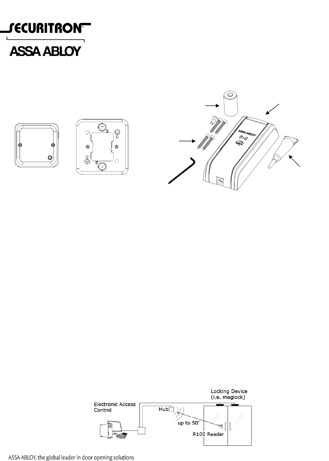
System Overview
The R100 Aperio
®
Reader (R100) installs in locations where wiring may be difficult or undesired for aesthetic
reasons. The R100 connects to the access control system through the included communication hub, and the
communication hub connects to the access control system with wiegand wiring typical of a wiegand reader.
When a credential card is presented to the reader, a request for access is sent wirelessly to the communication hub,
which then communicates through wiegand wiring to the access control system where the decision is made to grant
or deny access. When access is granted the access control system unlocks the locking device seperately.
Aperio Hub
Hub Mounting
Bracket
Glue
Reader
Screws
CR2 Battery
Hex
Wrench
Securitron Magnalock Corp.
Phoenix, AZ
800.624.5625
www.securitron.com
500-24050, Rev. B 2
DRAFT
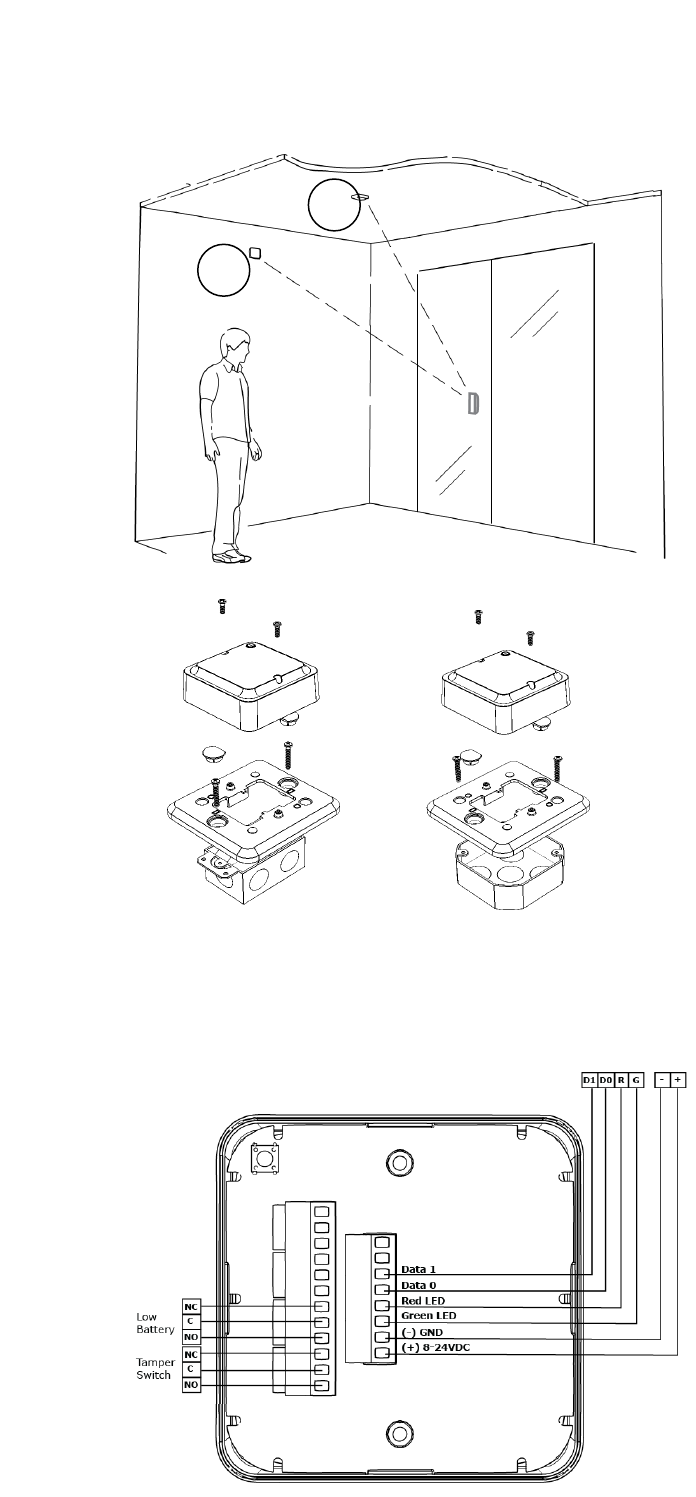
Locate the Hub
NOTE: The hub is not rated for use
in plenum air spaces.
1. ENSURE the hub is located:
• Near the top of a wall or on
the ceiling to reduce potential
for interference.
• Within fifty (50) feet of the
lock.
• Where there is a maximum of
two interior walls between the
hub and lock.
• In the interior lobby, for a
glass entryway.
Mount the Hub
1. MOUNT the hub on a single or
double gang box using the
included adapter plate.
Wire the Hub
NOTE 1: The Green LED and Red LED inputs control feedback that displays at the reader for
approved access (Green) or denied access (Red).
NOTE 2: The hub requires 8–24 VDC power (250 mA).
NOTE 3: The hub includes two form C relays
that can be used to transmit low
battery signal and a tamper signal.
1. ENSURE the Aperio Hub connects
to the Access Control system via
Wiegand wiring.
A
B
500-24050, Rev. B 3
DRAFT
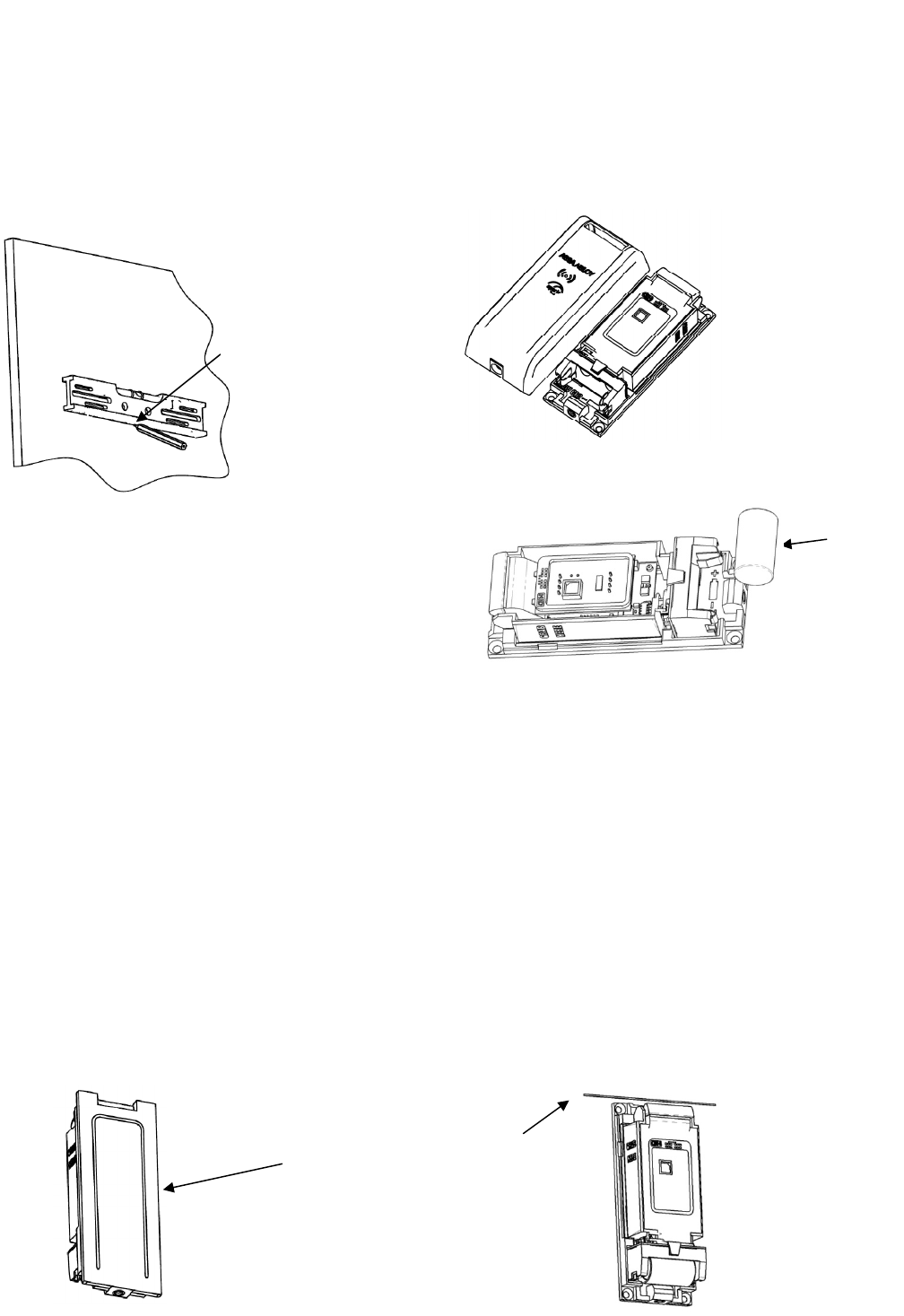
Prepare the R100
1. Before starting, MARK the position using a level.
2. HOLD the reader body on the outside of the window and POSITION it generally where you would like
it to mount.
Insert Battery
1. INSTALL the battery, ensuring correct orientation.
2. VERIFY the reader self tests and beeps once.
Mount the Unit
NOTE 1: The R100 can be mounted using glue or wood screws based on your needs.
NOTE 2: This following step allows oxygen to enter and aid in the curing process.
1. IF the R100 is mounted using glue,
THEN APPLY glue as a thin thread of glue applied to three sides of the back-plate as shown,
AND DO NOT USE tissue or a brush to spread the adhesive.
NOTE 1: The seal becomes functional within a short time and permanent after 24–72 hours.
NOTE 2: The rate of cure depends on the ambient relative humidity. The best results are achieved
when the relative humidity in the working environment is 40–60% at 22˚C. Lower humidity
leads to a slower cure. High humidity accelerates it, but may impair the final strength of the
bond.
2. Quickly AFFIX to the pre-marked area and HOLD or CLAMP until the adhesive has bonded (at least
five seconds).
Position
mark
Glue line
Battery
A pencil is used to mark
this
p
oint on the window
The cover is
pulled up while
pressing on the
LED
500-24050, Rev. B 4
DRAFT
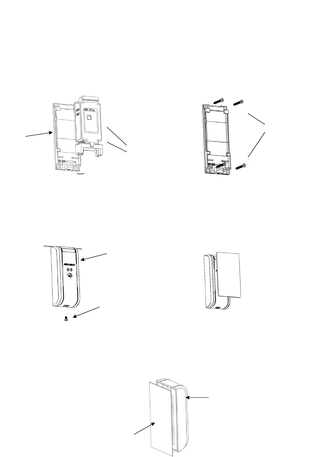
3. PERFORM the following if the R100 is mounted using wood screws.
a. SEPARATE the components by gripping the electronic module at the noted side areas.
b. ROCK UP, PULL DOWN, and LIFT OUT.
c. PRE-DRILL through the mounting plate at the four corners and INSERT wood screws.
d. REATTACH electronic module by sliding the top under the mounting plate’s raised edges and
PRESS DOWN firmly until it clicks.
Test the Reader
1. REATTACH cover and INSERT screw with the included hex wrench.
NOTE: A green LED indicates access is granted.
2. USE a credential known to the access control system to confirm it will read as desired.
3. REFER to the LED reference card for any other codes.
Optional: Attach Dress Cover
1. INSTALL a separately purchased dress cover (R100-DCA) on the inside of a glass mounting surface.
2. PEEL the backing from the adhesive on the cover and AFFIX to the window.
Cover
Screw
Dress Cover
R100 (rear view)
Side grip
areas
Mounting
Plate
Wood screws

500-24050, Rev. B 5
DRAFT
FCC Statement
This equipment has been tested and found to comply with the limits for a class B digital device, pursuant to part 15 of the FCC Rules.
These limits are designed to provide reasonable protection against harmful interference in a residential installation. This equipment
generates, uses, and can radiate radio frequency energy and if not installed and used in accordance with the instructions, may cause
harmful interference to radio communications. However, there is no guarantee that interference will not occur in a particular
installation. If this equipment does cause harmful interference to radio or television reception, which can be determined by turning
the equipment off and on, the user is encouraged to try to correct the interference by one or more of the following measures:
• Reorient or relocate the receiving antenna.
• Increase the separation between the equipment and receiver.
• Connect the equipment into an outlet on a circuit different from that to which the receiver is connected.
• Consult the dealer or an experienced radio/TV technician for help.
Operation with non-approved equipment is likely to result in interference to radio and TV reception. The user is cautioned that
changes and modifications made to the equipment without the approval of manufacturer could void the user’s authority to operate
this equipment.
IC Statement
This device complies with Industry Canada license-exempt RSS standards(s).
Operation is subject to the following two conditions:
(1) this device may not cause interference, and
(2) this device must accept any interference, including interference that may cause undesired operation.
Conformité aux normes FCC
Cet équipement a été testé et trouvé conforme aux limites pour un dispositif numérique de classe B, conformément à la Partie 15
des règlements de la FCC. Ces limites sont conçues pour fournir une protection raisonnable contre les interférences nuisibles dans
une installation résidentielle. Cet équipement génère, utilise et peut émettre des fréquences radio et, s'il n'est pas installé et utilisé
conformément ment aux instructions du fabricant, peut causer des interferences nuisibles aux communications radio. Rien ne
garantit cependant que l'interférence ne se produira pas dans une installation particulière. Si cet équipement provoque des
interférences nuisibles à la réception radio ou de télévision, qui peut être déterminé en comparant et en l'éteignant, l'utilisateur est
encouragé à essayer de corriger les interférence par une ou plusieurs des mesures suivantes:
• Réorienter ou déplacer l'antenne de réception.
• Augmenter la distance entre l'équipement et le récepteur.
• Branchez l'appareil dans une prise sur un circuit différent de celui auquel le récepteur est connecté.
• Consultez votre revendeur ou un technicien radio / TV pour assistance.Avertissement
Les changements ou modififications à cet appareil sans expressément approuvée par la partie responsable de conformité pourraient
annuler l'autorité de l'utilisateur de faire fonctionner cet équipement.
Conformité aux normes IC
Cet appareil est confrome avec Industrie Canada exempt de license RSS standard(s).
Son fonctionnement est souimes aux deux conditions suivantes:
(1) cet appareil ne peut causer d’interférences, et
(2) cet appareil doit accepter toute interference, y compris des interférences qui peuvent provoquer un fonctionnement indésirable
du périphérique.
For Technical Support please call 1-800-624-5625