Hanchett Entry Systems KS200 RFID Server Cabinet Lock User Manual 3085006 002 Rev A 031215a
Hanchett Entry Systems, Inc. RFID Server Cabinet Lock 3085006 002 Rev A 031215a
user guide
3085006.002 Rev. A 1
KS200-640
Server Cabinet Lock Series
Installation Instructions
HES, Inc.
Phoenix, AZ
1.800.626.7590
www.hesinnovations.com
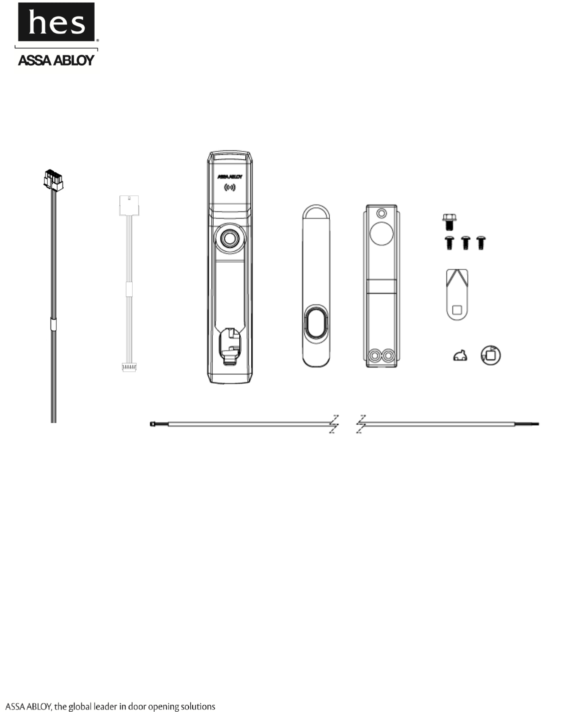
Package Contents
Recommended Tools
Approved RFID Credential
Phillips P2 driver
Optional Additional Tools:
Gang box to mount hub
SFIC Core for key override
Normally Open DPS Switches
Specifications
Voltage: 12–24 VDC ±10% (Power Supply not provided)
Power Consumption: <6W peak; <0.5W steady state
Operating Temperature: -10C to 50C
Holding Force: 250 lbs
Handling
Selector
Lock
Handle
Mounting
Plate
Mounting Screws
Cams (x3)
DPS Cable
SFIC
Cam
System Side
Interface Cable
Lock Side
Interface Cable Lock
3085006.002 Rev. A 2
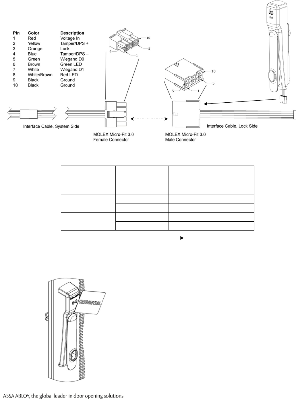
External Interface Signals Summary:
Lock Signal
Name
Lock Signal
Direction and Wire
Color
Electrical Interface Logic
Vin Input,
Red/24 AWG Power to Reader Input Power
Unlock Input,
Orange/24 AWG
Wetted Relay Contact
Closure
(0–35 VDC)
Active High
Tamper / Door
Position +
Output,
Yellow/24 AWG
Dry Contact
(0–35 VDC, <100mA)
Open = Unlocked
Closed = Locked
Tamper / Door
Position –
Output,
Blue/24 AWG
Dry Contact
(0–35 VDC, <100mA)
Open = Unlocked
Closed = Locked
Wiegand Data 0 Output,
Green/24 AWG 0–5 VDC Active Low
Wiegand Data 1 Output,
White/24 AWG 0–5 VDC Active Low
Green LED Input,
Brown/24 AWG 0–5 VDC Active Low
Red LED Input,
White/Brown/24 AWG 0–5 VDC Active Low
Ground/Return Input,
Black/24 AWG – –
LED Function: LED states are controlled and defined by the User’s EAC. Enabling the red and green
LEDs on the KS200 occurs via an active low (ground) signal.
Output Type: SIAAC-01-1996 Wiegand Output Compliant.
FCC Part 15, Compliant, Industry Canada Compliant
BHMA: A156.3, A156.36, A156.25 Compliant
Credentials Supported: 125kHz Proximity or 13.56MHz iCLASS, iCLASS SEOS, iCLASS SE, ISO 15693
ICLASS, ISO 14443A Mifare, Mifare Plus, Desfire SE, Desfire EV1, and NFC over HCE.
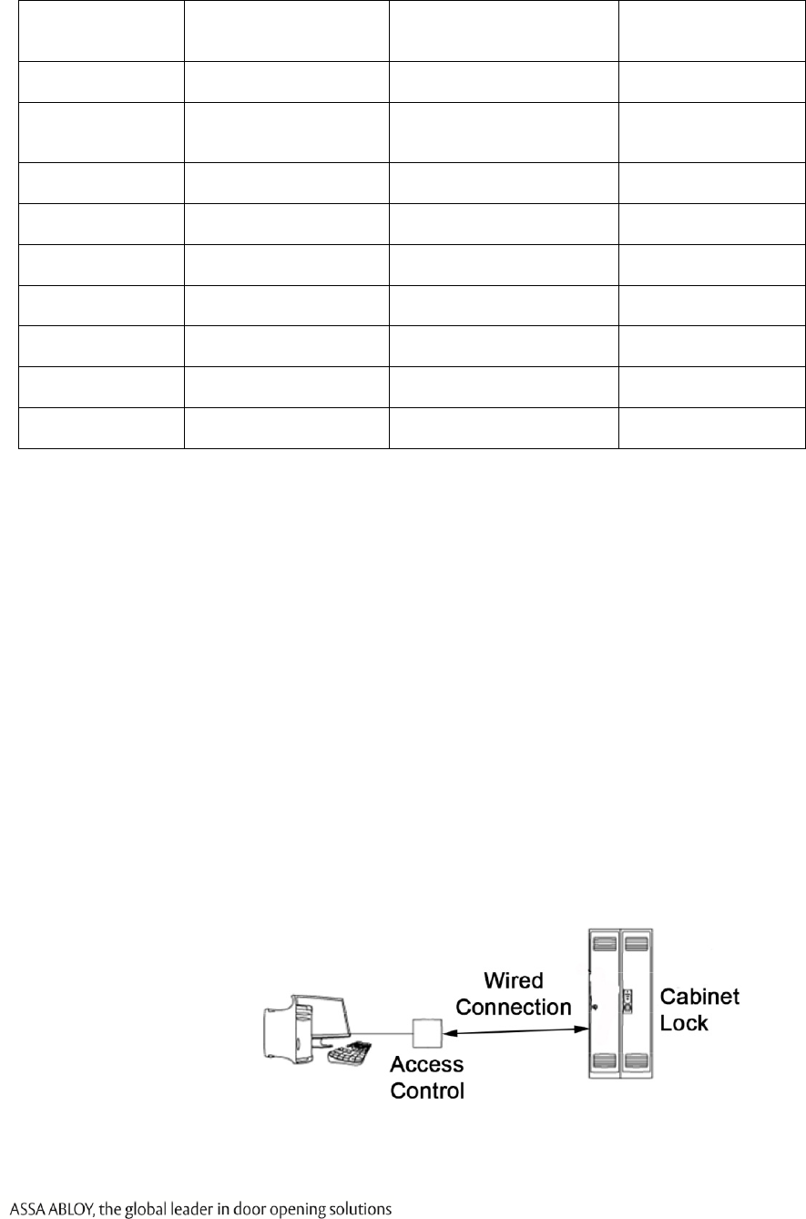
System Overview
The KS200 is an radio-frequency (RFID) lock for server cabinet installation applications. The lock is
capable of reading RFID credentials and providing that data to an electronic access control (EAC) system
via Wiegand data signaling. The EAC determines whether user access should be granted or denied.
When the EAC provides an active-high unlock signal to the lock in the access granted case, the KS200-
640 drives a motor to complete the unlock/lock cycle. EAC indication of user access/denial is provided
to the user by way of LED control inputs on the lock. Additional lock monitoring features (e.g., door
position, tamper) are monitored within the lock and status provided to the EAC.
3085006.002 Rev. A 3
Installation Steps
2. Preparing the Cabinet
3. Installing the Lock 4. Installing the Handing Selector
1. Installing an SFIC Core
5. Installing the Wiring 6. Testing the Lock
with the Access Control
3085006.002 Rev. A 4
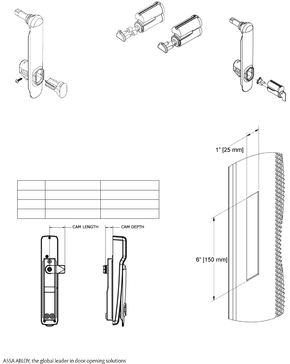
1. Installing an SFIC Core
NOTE 1: A key override (SFIC) provides a backup entry method in the rare case the KS200 or EAC
is inactive (Recommended).
NOTE 2: The included SFIC cam has been tested with Medeco and Sargent 6- or 7-pin SFIC cores.
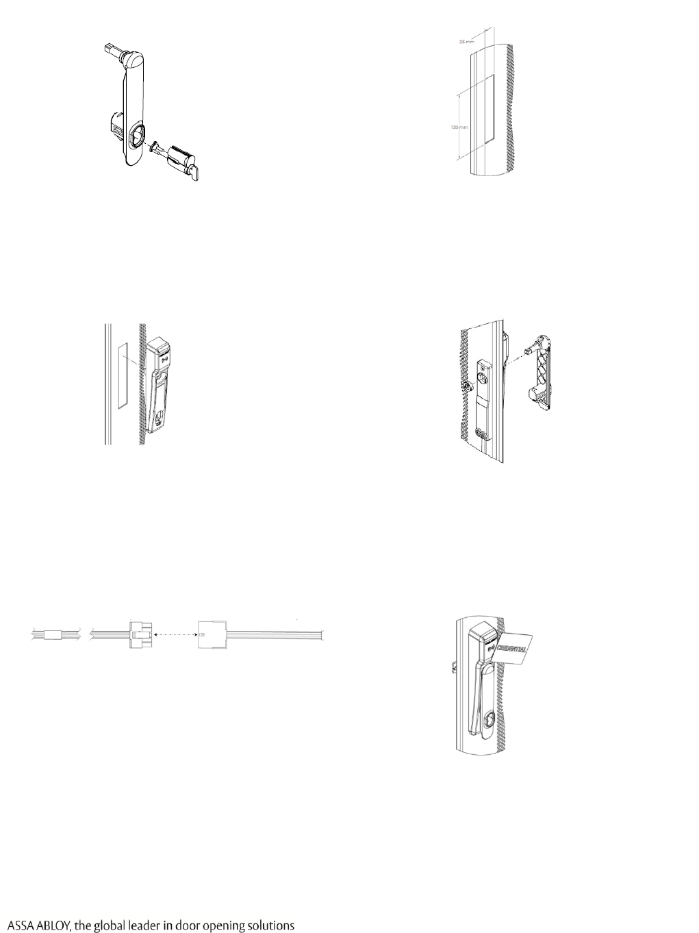
2. Preparing the Cabinet
1. LOCATE the 1” [25 mm] x 6” [150 mm] lock cutout on
the door (some doors may require modification).
2. ENSURE power is available at the rack.
3. RE-USE the existing cam, if possible.
NOTE: Three cams are supplied.
CAM CAM LENGTH CAM DEPTH
CAM 1 1-1/2” [38 mm] 5/8” [16 mm]
CAM 2 1-1/2” [38 mm] 15/16” [24 mm]
CAM 3 1-3/4” [45 mm] 7/8” [22.5 mm]
1. REMOVE plug
from handle
7-pin
6-pin
2. INSERT core into
SFIC cam using
the included
spacers.
3. INSERT SFIC
cam into lock
3085006.002 Rev. A 5
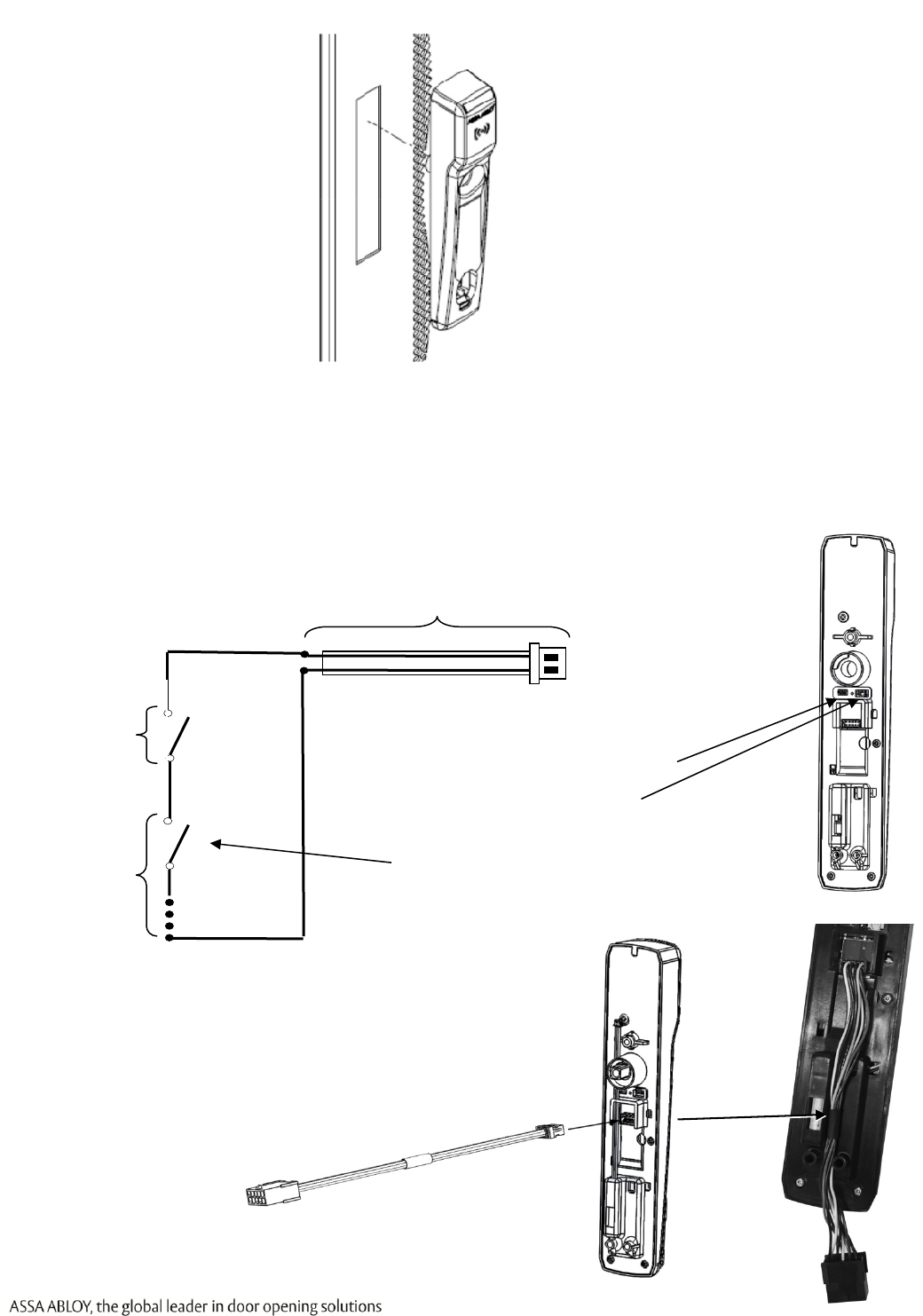
3. Installing the Lock
3. SLIDE lock into cutout.
NOTE: (Optional) The DPS signal is closed when the handle
is resting in its locked position. The DPS circuit can
be extended to include normally open DPS switches
arranged in a series to monitor additional doors and
panels.
DPS Extension Cable
DPS
Switches
(SPST-
NO): As
Needed
Switch #1
(SPST-NO):
Provided
2. PERFORM the following to
extend the DPS Circuit.
a. REMOVE the DPS jumper.
b. CONNECT the included
DPS extension cable.
c. CONNECT additional
normally-open DPS
switches as shown to
monitor additional panels.
3. CONNECT the female, 10-position
Hirose™ connector on the lock side
interface cable to the KS200.
4. ENSURE the lock side interface
cable will properly protrude from
the bottom of the KS200
prior to attaching the rear bracket.
3085006.002 Rev. A 6
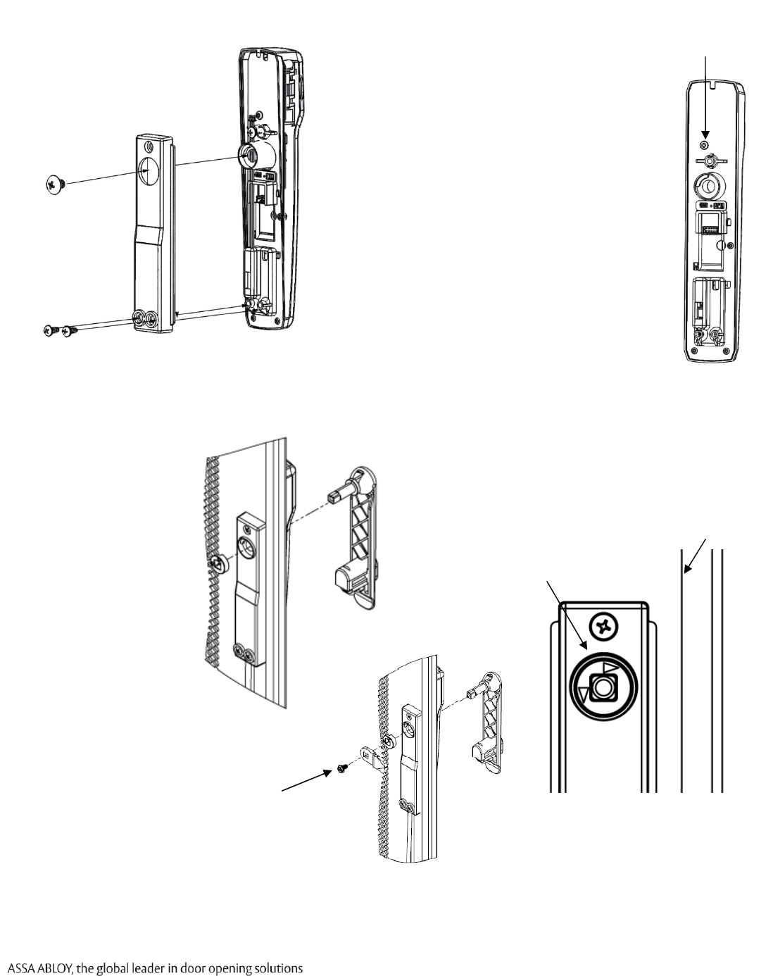
4. Installing the Handing Selector
CAUTION! Inserting/snapping the handle all the way in will lock the lever
2. POSITION the arrows to
point toward the door
edge.
1. INSERT handing
selector into lock.
6. ENSURE that the lock is fully
secured and flush to the mounting
surface in order to depress
tamper switch on back of device
for correct operation.
Tamper Switch
NOTE: If the tamper switch is
not fully depressed, the
lock opens the
Tamper/DPS+/- contact.
5. ATTACH rear bracket with screws.
7. IF the tamper switch is not fully
closed,
THEN REMOVE the tamper
contact,
AND ENSURE the lock is closed.
3. INSERT and SECURE
cam with screw.
Door edge
3085006.002 Rev. A 7
5. Attaching the Wiring
Wire AWG Supply Voltage Allowed Cable Length (ft.)*
20 AWG
12 419
24 3217
22 AWG
12 264
24 2023
24 AWG
12 166
24 1272
* Round trip loss. V = 2 x I x R x xft xft = V / (2 x I x R)
6. Testing the Lock with the Access Control System
1. TEST the lock with a known good credential to confirm it will open as desired when installed.
a. PRESENT a credential known to the EAC.
b. LIFT lever and TURN to open the cabinet.
1. CONNECT the 10-position Molex Micro-Fit 3.0™ Cable between the KS200
a
n
d
t
h
e
EA
C
.
2. ENSURE the following power cabling guidelines are followed:

3085006.002 Rev. A 8
FCC Statement
This equipment has been tested and found to comply with the limits for a class B digital device, pursuant to part 15
of the FCC Rules. These limits are designed to provide reasonable protection against harmful interference in a
residential installation. This equipment generates, uses, and can radiate radio frequency energy and if not installed
and used in accordance with the instructions, may cause harmful interference to radio communications. However,
there is no guarantee that interference will not occur in a particular installation. If this equipment does cause
harmful interference to radio or television reception, which can be determined by turning the equipment off and on,
the user is encouraged to try to correct the interference by one or more of the following measures:
Reorient or relocate the receiving antenna.
Increase the separation between the equipment and receiver.
Connect the equipment into an outlet on a circuit different from that to which the receiver is connected.
Consult the dealer or an experienced radio/TV technician for help.
Operation with non-approved equipment is likely to result in interference to radio and TV reception. The user is
cautioned that changes and modifications made to the equipment without the approval of manufacturer could void
the user’s authority to operate this equipment.
IC Statement
This device complies with Industry Canada license-exempt RSS standards(s). Operation is subject to the following
two conditions:
(1) this device may not cause interference, and
(2) this device must accept any interference, including interference that may cause undesired operation.
CE Statement
HES hereby declares that these proximity readers are in compliance with the essential requirements and other
relevant provisions of Directive 1999/5/EC.
Conformité aux normes FCC
Cet équipement a été testé et trouvé conforme aux limites pour un dispositif numérique de classe B, conformément
à la Partie 15 des règlements de la FCC. Ces limites sont conçues pour fournir une protection raisonnable contre les
interférences nuisibles dans une installation résidentielle. Cet équipement génère, utilise et peut émettre des
fréquences radio et, s'il n'est pas installé et utilisé conformément ment aux instructions du fabricant, peut causer
des interferences nuisibles aux communications radio. Rien ne garantit cependant que l'interférence ne se produira
pas dans une installation particulière. Si cet équipement provoque des interférences nuisibles à la réception radio
ou de télévision, qui peut être déterminé en comparant et en l'éteignant, l'utilisateur est encouragé à essayer de
corriger les interférence par une ou plusieurs des mesures suivantes:
Réorienter ou déplacer l'antenne de réception.
Augmenter la distance entre l'équipement et le récepteur.
Branchez l'appareil dans une prise sur un circuit différent de celui auquel le récepteur est connecté.
Consultez votre revendeur ou un technicien radio / TV pour assistance.Avertissement
Les changements ou modififications à cet appareil sans expressément approuvée par la partie responsable de
conformité pourraient annuler l'autorité de l'utilisateur de faire fonctionner cet équipement.
Conformité aux normes IC
Cet appareil est confrome avec Industrie Canada exempt de license RSS standard(s).
Son fonctionnement est souimes aux deux conditions suivantes:
(1) cet appareil ne peut causer d’interférences, et
(2) cet appareil doit accepter toute interference, y compris des interférences qui peuvent provoquer un
fonctionnement indésirable du périphérique.
Conformité aux normes CE
HES déclare par la présente que ces lecteurs à proximité sont conformes aux exigences essentielles et aux autres
stipulations pertinentes de la Directive 1999/5/CE.
For Technical Support please call 1-800-626-7590
© 2015
,
Hanchett Entry Systems, Inc., an ASSA ABLOY Group Company.